EP2332305B1 - Method and apparatus for the exclusive identification of control signals in a railway electric line - Google Patents
Method and apparatus for the exclusive identification of control signals in a railway electric line Download PDFInfo
- Publication number
- EP2332305B1 EP2332305B1 EP09807497.4A EP09807497A EP2332305B1 EP 2332305 B1 EP2332305 B1 EP 2332305B1 EP 09807497 A EP09807497 A EP 09807497A EP 2332305 B1 EP2332305 B1 EP 2332305B1
- Authority
- EP
- European Patent Office
- Prior art keywords
- signal
- power supply
- block
- unambiguous
- cable
- Prior art date
- Legal status (The legal status is an assumption and is not a legal conclusion. Google has not performed a legal analysis and makes no representation as to the accuracy of the status listed.)
- Active
Links
Images
Classifications
-
- H—ELECTRICITY
- H04—ELECTRIC COMMUNICATION TECHNIQUE
- H04L—TRANSMISSION OF DIGITAL INFORMATION, e.g. TELEGRAPHIC COMMUNICATION
- H04L27/00—Modulated-carrier systems
- H04L27/18—Phase-modulated carrier systems, i.e. using phase-shift keying
- H04L27/24—Half-wave signalling systems
-
- B—PERFORMING OPERATIONS; TRANSPORTING
- B61—RAILWAYS
- B61L—GUIDING RAILWAY TRAFFIC; ENSURING THE SAFETY OF RAILWAY TRAFFIC
- B61L5/00—Local operating mechanisms for points or track-mounted scotch-blocks; Visible or audible signals; Local operating mechanisms for visible or audible signals
- B61L5/12—Visible signals
- B61L5/18—Light signals; Mechanisms associated therewith, e.g. blinders
- B61L5/1809—Daylight signals
- B61L5/1881—Wiring diagrams for power supply, control or testing
-
- B—PERFORMING OPERATIONS; TRANSPORTING
- B61—RAILWAYS
- B61L—GUIDING RAILWAY TRAFFIC; ENSURING THE SAFETY OF RAILWAY TRAFFIC
- B61L7/00—Remote control of local operating means for points, signals, or track-mounted scotch-blocks
- B61L7/06—Remote control of local operating means for points, signals, or track-mounted scotch-blocks using electrical transmission
- B61L7/08—Circuitry
- B61L7/10—Circuitry for light signals, e.g. for supervision, back-signalling
-
- H—ELECTRICITY
- H04—ELECTRIC COMMUNICATION TECHNIQUE
- H04B—TRANSMISSION
- H04B3/00—Line transmission systems
- H04B3/54—Systems for transmission via power distribution lines
-
- H—ELECTRICITY
- H04—ELECTRIC COMMUNICATION TECHNIQUE
- H04J—MULTIPLEX COMMUNICATION
- H04J13/00—Code division multiplex systems
- H04J13/0007—Code type
- H04J13/004—Orthogonal
-
- H—ELECTRICITY
- H04—ELECTRIC COMMUNICATION TECHNIQUE
- H04B—TRANSMISSION
- H04B2203/00—Indexing scheme relating to line transmission systems
- H04B2203/54—Aspects of powerline communications not already covered by H04B3/54 and its subgroups
- H04B2203/5404—Methods of transmitting or receiving signals via power distribution lines
- H04B2203/5412—Methods of transmitting or receiving signals via power distribution lines by modofying wave form of the power source
Definitions
- the present invention refers to a method and to an apparatus for encoding a signal on an electric line for railway signals.
- the present method is capable of exclusively identifying the correct power supply between a central unit and a plurality of signal devices, such as for example the light signal lamps, and controlling the soundness of such connections and - only in case no problems are detected - electric connection from the central unit or control apparatus to such Field controller units.
- the cabling from the control station to the various Field controller units is obtained through a plurality of sheets passing through which is one or more cables each bearing a power supply and/or control signal for a respective controller unit.
- the insulation layer of each cable may possibly end up being damaged.
- the control signal or direct power supply to a specific controller unit may be sent in a non-unique manner thereto, but received also by a different controller unit (and vice versa) due to such lack of insulation caused by such damage - even partial - on the cable.
- the consequence is that in order to avoid potentially hazardous situations all controller units involved in the malfunction are deactivated from the control unit, hence disabling the corresponding line section.
- the measurement environment is extremely noisy - just imagine the traction noise of electric locomotives - and the measurement method must be practically immune to noise signals even of high levels.
- the Applicant thought of how a control unit may be enabled to identify an event of such type, in order to intervene promptly to monitor and/or solve the malfunction.
- the present invention overcomes the abovementioned drawbacks by providing a system wherein transmitted on the cable coming from the control unit that supplies the Field controller units is an unambiguous digital word for each of the Field controller units to be supplied using the CDMA (Code Division Multiple Access) encoding.
- CDMA Code Division Multiple Access
- Such encoding is currently used for encoding signals in mobile phones and it is substantially a technique for access, by several sources of information, to the same transmission channel, by using the same frequency band, which consists in associating - to the information transmitted by each of these sources - a code capable of identifying it in a unique manner with respect to the rest and capable of allowing a receiver, to selectively extract information associated to each of them.
- An aspect of the present invention regards an apparatus for exclusive identification of control signals along an electric line according to the characteristics of claim 1.
- a further aspect of the present invention regards a method for exclusive identification of control signals along an electric line according to the characteristics of claim 6.
- the apparatus according to the present invention is applied on a power supply line A which controls a Field controller unit (represented by the circuit of a lamp L in the exemplified case in question) and a control unit C adapted to generate the power supply signal.
- a Field controller unit represented by the circuit of a lamp L in the exemplified case in question
- a control unit C adapted to generate the power supply signal.
- the power supply signal is typically an alternating voltage having for example a 50 Hz, 83.3 Hz frequency or other frequencies.
- the apparatus according to the present invention comprises a circuit for transmitting such power supply signal adapted to associate an unambiguous and orthogonal code word thereto. Such transmission may be generated through phase modulation, case (a) or through amplitude modulation, case (b).
- Case (a) consists in providing a preset number of positive and negative half-waves of such alternating current according to a predetermined sequence.
- a so-called spread word S for example made up of 16 chips, wherein each chip is equivalent to a sinusoidal cycle at the considered frequency, wherein the chip with value "1" provides for the sinusoidal cycle at the considered frequency with zero-phase, while the chip with value "0” provides for the sinusoidal cycle with phase 180°.
- Case (b) consists in providing a preset number of pulses (bits) having a defined duration, for example 20 msec, which is multiplied by a carrier sinusoidal signal having a multiple frequency with respect to the bit frequency, with amplitude of suitable value.
- bits having a defined duration, for example 20 msec
- a carrier sinusoidal signal having a multiple frequency with respect to the bit frequency, with amplitude of suitable value.
- S for example made up of 16 chips, where for each value logic "1" bit there is the presence of the carrier while for each logic "0" bit there is no carrier.
- each unambiguous digital word is orthogonal to the others.
- the term orthogonal is used to indicate that the scalar product between two orthogonal words is zero. Exploiting such property, the present invention proposes detecting (extracting) the power supply signal from each power supply cable of a lamp. Under normal conditions, such signal must contain an unambiguous word or may contain several unambiguous words (in case of malfunction).
- the presence of a correct unambiguous word may be verified and thus detect the power supply signal insulating it from noise.
- other power supply signals may be detected, verifying the presence of one or more other unambiguous words, due for example to the deterioration of the electric insulation between the cables.
- the apparatus may emit a disabling signal to be used to cut-off the power supply of such lamp, for example by suitably commanding a control relay.
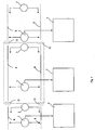
- Illustrated in figure 1 is an embodiment of apparatus according to the present invention comprising a first block 2 for extracting the signal from power supply line A, a first processing block 3 and a first power supply block 4.
- the apparatus also comprises a second block 2' for extracting the signal from the power supply line A, a second processing block 3' and a second power supply block 4'.
- the first 2, 3 and 4 and second blocks 2' 3' and 4' operate parallel with respect to each other, thus the signal is extracted and processed twice, and the processing operations carried out are compared to each other by means of a comparison block 5, suitable to ascertain coincidence thereof and thus activate a control block 6.
- the power supply block 3 supplies direct voltage to the other blocks of the apparatus and comprises a diodes rectifier bridge connected to the power supply line A which carries out the AC/DC conversion.
- the signal extraction block may suitably comprise a block for amplifying and filtering the signal extracted from the line and a timer block T capable of monitoring the signal for a period of time sufficient to intercept the unambiguous word for example in case there is an intermittent power supply signal.
- the extracted signal is subsequently sent to the processing block which comprises a microprocessor and at least one analogue/digital converter for such extracted signal.
- Comparison between the extracted signal and the previously memorised unambiguous codes is carried out in such processing block 3 or 3', preferably digitally, verifying the presence of the unambiguous word/s received emitting a signal for identifying the words themselves.
- Such signal may be sent to the comparison block 5 for comparison with the analogous signal obtained from the second blocks.
- the apparatus according to the present invention when in the condition of identifying solely its unambiguous word, shall maintain an electromechanical or electronic switch for connecting the field controller unit with the cable coming from the control unit energised, while in case the presence of one or more unambiguous word is detected it shall deactivate the energising of such switch.
- the apparatus according to the present invention may be applied to each lamp in such a manner that it is the lamp itself to "be disconnected” by deactivating such relay.
- the apparatus may solely communicate the presence of malfunction and leave the task of disconnecting the Field controller unit in question to the control unit.
Landscapes
- Engineering & Computer Science (AREA)
- Computer Networks & Wireless Communication (AREA)
- Signal Processing (AREA)
- Mechanical Engineering (AREA)
- Power Engineering (AREA)
- Train Traffic Observation, Control, And Security (AREA)
- Electric Propulsion And Braking For Vehicles (AREA)
- Remote Monitoring And Control Of Power-Distribution Networks (AREA)
Description
- The present invention refers to a method and to an apparatus for encoding a signal on an electric line for railway signals.
- The present method is capable of exclusively identifying the correct power supply between a central unit and a plurality of signal devices, such as for example the light signal lamps, and controlling the soundness of such connections and - only in case no problems are detected - electric connection from the central unit or control apparatus to such Field controller units.
- Usually, the cabling from the control station to the various Field controller units is obtained through a plurality of sheets passing through which is one or more cables each bearing a power supply and/or control signal for a respective controller unit. At times, given the environment strongly subjected to external interferences, such as for example the passage of trains, various kinds of maintenance operations that imply excavating and invasive operations on the ground on which such sheaths lie, the insulation layer of each cable may possibly end up being damaged. Should such event occur, the control signal or direct power supply to a specific controller unit may be sent in a non-unique manner thereto, but received also by a different controller unit (and vice versa) due to such lack of insulation caused by such damage - even partial - on the cable. Thus, the consequence is that in order to avoid potentially hazardous situations all controller units involved in the malfunction are deactivated from the control unit, hence disabling the corresponding line section.
- Furthermore, the measurement environment is extremely noisy - just imagine the traction noise of electric locomotives - and the measurement method must be practically immune to noise signals even of high levels.
- The Applicant thought of how a control unit may be enabled to identify an event of such type, in order to intervene promptly to monitor and/or solve the malfunction.
- Document
US6570493B1 proposes a method and a system for controlling the connection of an electric load to the power supply line provided with an unambiguous code for that particular electric load. Obviously, in a noisy environment like the one described above even this system could fail to signal the correct information in that the unambiguous code could erroneously not be received both in case of strong electric noise and in case of short-circuit with a power supply cable meant for an electric load and thus with another unambiguous code. - The present invention overcomes the abovementioned drawbacks by providing a system wherein transmitted on the cable coming from the control unit that supplies the Field controller units is an unambiguous digital word for each of the Field controller units to be supplied using the CDMA (Code Division Multiple Access) encoding.
- Such encoding is currently used for encoding signals in mobile phones and it is substantially a technique for access, by several sources of information, to the same transmission channel, by using the same frequency band, which consists in associating - to the information transmitted by each of these sources - a code capable of identifying it in a unique manner with respect to the rest and capable of allowing a receiver, to selectively extract information associated to each of them.
- In such manner, it is possible to monitor whether - in a determined cable for supplying a Field controller unit - there is a supply signal not intended to supply this controller unit, or a signal due to malfunction. Advantageously, in case of detection of a further presence of a different code word apart from the one provided for, it is possible to intervene on the line cutting off power supply.
- An aspect of the present invention regards an apparatus for exclusive identification of control signals along an electric line according to the characteristics of claim 1.
- A further aspect of the present invention regards a method for exclusive identification of control signals along an electric line according to the characteristics of claim 6.
- Characteristics and advantages of the method and apparatus according to the present invention shall be more clear and apparent from the following description, exemplifying and non-limiting, of an embodiment provided with reference to the attached figure which represents a block diagram of the apparatus according to the invention.
- With reference to the abovementioned figure the apparatus according to the present invention is applied on a power supply line A which controls a Field controller unit (represented by the circuit of a lamp L in the exemplified case in question) and a control unit C adapted to generate the power supply signal.
- The power supply signal is typically an alternating voltage having for example a 50 Hz, 83.3 Hz frequency or other frequencies. The apparatus according to the present invention comprises a circuit for transmitting such power supply signal adapted to associate an unambiguous and orthogonal code word thereto. Such transmission may be generated through phase modulation, case (a) or through amplitude modulation, case (b).
- Case (a) consists in providing a preset number of positive and negative half-waves of such alternating current according to a predetermined sequence. In particular, a so-called spread word S, for example made up of 16 chips, wherein each chip is equivalent to a sinusoidal cycle at the considered frequency, wherein the chip with value "1" provides for the sinusoidal cycle at the considered frequency with zero-phase, while the chip with value "0" provides for the sinusoidal cycle with phase 180°.
- Case (b) consists in providing a preset number of pulses (bits) having a defined duration, for example 20 msec, which is multiplied by a carrier sinusoidal signal having a multiple frequency with respect to the bit frequency, with amplitude of suitable value. In particular, generated is a so-called spread word S, for example made up of 16 chips, where for each value logic "1" bit there is the presence of the carrier while for each logic "0" bit there is no carrier. Advantageously, each unambiguous digital word is orthogonal to the others. According to the present invention, the term orthogonal is used to indicate that the scalar product between two orthogonal words is zero. Exploiting such property, the present invention proposes detecting (extracting) the power supply signal from each power supply cable of a lamp. Under normal conditions, such signal must contain an unambiguous word or may contain several unambiguous words (in case of malfunction).
- By carrying out the scalar product between such signal and the various unambiguous words, the presence of a correct unambiguous word may be verified and thus detect the power supply signal insulating it from noise. In addition, other power supply signals may be detected, verifying the presence of one or more other unambiguous words, due for example to the deterioration of the electric insulation between the cables.
- After such verification, should malfunction be detected, the apparatus may emit a disabling signal to be used to cut-off the power supply of such lamp, for example by suitably commanding a control relay. Illustrated in
figure 1 is an embodiment of apparatus according to the present invention comprising a first block 2 for extracting the signal from power supply line A, afirst processing block 3 and a firstpower supply block 4. - Furthermore, the apparatus also comprises a second block 2' for extracting the signal from the power supply line A, a second processing block 3' and a second power supply block 4'. The first 2, 3 and 4 and second blocks 2' 3' and 4' operate parallel with respect to each other, thus the signal is extracted and processed twice, and the processing operations carried out are compared to each other by means of a comparison block 5, suitable to ascertain coincidence thereof and thus activate a control block 6.
- In particular, the
power supply block 3 supplies direct voltage to the other blocks of the apparatus and comprises a diodes rectifier bridge connected to the power supply line A which carries out the AC/DC conversion. The signal extraction block may suitably comprise a block for amplifying and filtering the signal extracted from the line and a timer block T capable of monitoring the signal for a period of time sufficient to intercept the unambiguous word for example in case there is an intermittent power supply signal. - The extracted signal is subsequently sent to the processing block which comprises a microprocessor and at least one analogue/digital converter for such extracted signal.
- Comparison between the extracted signal and the previously memorised unambiguous codes is carried out in
such processing block 3 or 3', preferably digitally, verifying the presence of the unambiguous word/s received emitting a signal for identifying the words themselves. Such signal may be sent to the comparison block 5 for comparison with the analogous signal obtained from the second blocks. - Finally, the apparatus according to the present invention present on the field controller unit, when in the condition of identifying solely its unambiguous word, shall maintain an electromechanical or electronic switch for connecting the field controller unit with the cable coming from the control unit energised, while in case the presence of one or more unambiguous word is detected it shall deactivate the energising of such switch.
- The apparatus according to the present invention may be applied to each lamp in such a manner that it is the lamp itself to "be disconnected" by deactivating such relay. Alternatively, the apparatus may solely communicate the presence of malfunction and leave the task of disconnecting the Field controller unit in question to the control unit.
Claims (7)
- Apparatus for exclusive identification of control signals in an electric railway line along an alternating current power supply (A), consisting of a plurality of power cables, each cable connecting a central unit (C) to a single signal device (L) of a plurality of signal devices (L), the apparatus comprising a circuit for transmitting such power supply signals adapted to associate to each of the power supply signals an unambiguous code word to each device to be supplied with power which consists in providing a phase modulation or an amplitude modulation in the alternating power supply signal, at least a block (2,2') for extracting the power supply signal from each cable of the line and at least one processing block (3,3') adapted to compare such predetermined unambiguous codes with the extracted signals,
characterized in that the unambiguous code word associated to each power cable is orthogonal with respect to the one associated to another cable. - Apparatus according to claim 1, further comprising at least one power block (4,4') which supplies a direct current to the other blocks of the apparatus and comprises a bridge for rectifying the diodes connected to the power supply line (A) which performs the AC/DC conversion.
- Apparatus according to claim 1, wherein the block for extracting the signal comprises a block for amplifying and filtering the signal extracted from the line and a timer block T, capable of monitoring the signal for a period of time sufficient to intercept the unambiguous orthogonal word
- Apparatus according to claim 1, wherein the power supply signal is extracted and processed at least twice, through first and second extraction and processing blocks, and the processing results are compared to each other through a comparison block (5), adapted to check their coincidence and thus activate a control block (6).
- Apparatus according to claim 1, wherein the processing block comprises a microprocessor and at least one analogue/digital converter for such extracted signal.
- Method for exclusive identification of control signals in an electric railway line along an alternating current power supply line (A), consisting in a plurality of power cables, each cable connecting a central unit (C) to a single signal device (L) of a plurality of signal devices (L), characterized in that it comprises the following steps:a) transmitting an alternating current supply signal on each of said cables,b) associating an unambiguous code word to each of such signals, providing a phase modulation or an amplitude modulation in the alternating power supply signal according to a predetermined sequence, the unambiguous code word associated to each power cable being orthogonal with respect to the one associated to another cable,c) extracting the power supply signal from such line,d)comparing such signal with the previously stored unambiguous code words,e) detecting the presence of one or more code words in said extracted signal,f) emitting a signal for identifying the detected words.
- Method according to claim 6, further comprising the step of disconnecting the signal device in case the presence of several unambiguous words is detected in the power supply signal extracted from the power cable of such device.
Priority Applications (2)
| Application Number | Priority Date | Filing Date | Title |
|---|---|---|---|
| PL09807497T PL2332305T3 (en) | 2008-08-28 | 2009-08-25 | Method and apparatus for the exclusive identification of control signals in a railway electric line |
| SI200930992T SI2332305T1 (en) | 2008-08-28 | 2009-08-25 | Method and apparatus for the exclusive identification of control signals in a railway electric line |
Applications Claiming Priority (2)
| Application Number | Priority Date | Filing Date | Title |
|---|---|---|---|
| ITMI2008A001549A IT1391429B1 (en) | 2008-08-28 | 2008-08-28 | METHOD AND APPARATUS FOR THE EXCLUSIVE IDENTIFICATION OF SIGNALS OF CONTROL ALONG A RAILWAY ELECTRIC LINE |
| PCT/IB2009/006644 WO2010035088A2 (en) | 2008-08-28 | 2009-08-25 | Method and apparatus for exclusive identification of control signals along an electric railway line |
Publications (2)
| Publication Number | Publication Date |
|---|---|
| EP2332305A2 EP2332305A2 (en) | 2011-06-15 |
| EP2332305B1 true EP2332305B1 (en) | 2014-05-07 |
Family
ID=40802020
Family Applications (1)
| Application Number | Title | Priority Date | Filing Date |
|---|---|---|---|
| EP09807497.4A Active EP2332305B1 (en) | 2008-08-28 | 2009-08-25 | Method and apparatus for the exclusive identification of control signals in a railway electric line |
Country Status (7)
| Country | Link |
|---|---|
| EP (1) | EP2332305B1 (en) |
| HR (1) | HRP20140700T1 (en) |
| IT (1) | IT1391429B1 (en) |
| PL (1) | PL2332305T3 (en) |
| PT (1) | PT2332305E (en) |
| SI (1) | SI2332305T1 (en) |
| WO (1) | WO2010035088A2 (en) |
Family Cites Families (4)
| Publication number | Priority date | Publication date | Assignee | Title |
|---|---|---|---|---|
| GB1527073A (en) * | 1975-09-12 | 1978-10-04 | Sangamo Weston | Signalling systems |
| US4467314A (en) * | 1982-03-29 | 1984-08-21 | Westinghouse Electric Corp. | Electric utility communication system with field installation terminal and load management terminal with remotely assignable unique address |
| DE3215081A1 (en) * | 1982-04-22 | 1983-11-03 | Siemens AG, 1000 Berlin und 8000 München | SYSTEM FOR TRANSMITTING INFORMATION TELEGRAMS |
| US6570493B1 (en) * | 2000-05-03 | 2003-05-27 | Eliahu Lames | Method and apparatus for operating an electrical device |
-
2008
- 2008-08-28 IT ITMI2008A001549A patent/IT1391429B1/en active
-
2009
- 2009-08-25 WO PCT/IB2009/006644 patent/WO2010035088A2/en not_active Ceased
- 2009-08-25 PL PL09807497T patent/PL2332305T3/en unknown
- 2009-08-25 PT PT98074974T patent/PT2332305E/en unknown
- 2009-08-25 SI SI200930992T patent/SI2332305T1/en unknown
- 2009-08-25 EP EP09807497.4A patent/EP2332305B1/en active Active
- 2009-08-25 HR HRP20140700AT patent/HRP20140700T1/en unknown
Also Published As
| Publication number | Publication date |
|---|---|
| HRP20140700T1 (en) | 2014-09-12 |
| EP2332305A2 (en) | 2011-06-15 |
| SI2332305T1 (en) | 2014-09-30 |
| ITMI20081549A1 (en) | 2010-02-28 |
| PT2332305E (en) | 2014-07-28 |
| WO2010035088A2 (en) | 2010-04-01 |
| IT1391429B1 (en) | 2011-12-23 |
| PL2332305T3 (en) | 2014-10-31 |
| WO2010035088A3 (en) | 2010-07-01 |
Similar Documents
| Publication | Publication Date | Title |
|---|---|---|
| EP2850708B1 (en) | Method and apparatus for localizing and quenching an arc | |
| CN110999005B (en) | Ground fault location in an IT system | |
| TWI370253B (en) | Method and apparatus for detecting the phase wiring of an arbitrary unknown phase voltage relative to a reference phase voltage | |
| CA2465026A1 (en) | Method and apparatus for detecting shorted rectifying control elements of an engine driven power source for a welding-type system | |
| EP3196095B1 (en) | System and method for detecting broken rails on a railway line | |
| CN106208417B (en) | Wireless charging system and method for rapidly identifying number of wireless charging receiving terminals | |
| CN110356432B (en) | Method and system for fault detection of track circuit | |
| US20140014783A1 (en) | Device for detecting the occupied or available status of a track segment and method for operating such a device | |
| RU2636154C2 (en) | Method of determination of short circuit place at electrified railway station | |
| EP2608172A1 (en) | Anti-theft device for electrical cables | |
| WO2010035088A2 (en) | Method and apparatus for exclusive identification of control signals along an electric railway line | |
| CN108512193B (en) | System for transmitting energy and data | |
| EP2315689B1 (en) | Method and apparatus for testing the insulation of a track circuit | |
| KR101740752B1 (en) | Method and apparatus for determination of the track occupancy state of a track circuit on a railway line via sequential decoding | |
| US9836558B2 (en) | Electrical system mapping utilizing plug-in modules | |
| EP2328790B1 (en) | Method and apparatus for determining the occupation state of the circuit of a direct current track circuit in a railway line | |
| WO2009130152A1 (en) | Method, apparatus and computer program product for use with interlocking systems | |
| EP3381762B1 (en) | System and method for detecting the presence of a train on a railway track | |
| WO2014109348A1 (en) | Traffic signal control system, traffic signal control device, and lamp control device | |
| RU2510031C1 (en) | Method to determine availability or unavailability of voltage in operating power plant | |
| US20080129309A1 (en) | Method For Detecting and Locating a Ground Failure In an Electrical Line | |
| Allan et al. | GE/RT8015 and safety [railway EMC assurance] | |
| JP2002311077A (en) | Transmission line fault location system | |
| KR20100073813A (en) | Auto current dividing apparatus of an audio frequency electrical joint apparatus |
Legal Events
| Date | Code | Title | Description |
|---|---|---|---|
| PUAI | Public reference made under article 153(3) epc to a published international application that has entered the european phase |
Free format text: ORIGINAL CODE: 0009012 |
|
| 17P | Request for examination filed |
Effective date: 20110222 |
|
| AK | Designated contracting states |
Kind code of ref document: A2 Designated state(s): AT BE BG CH CY CZ DE DK EE ES FI FR GB GR HR HU IE IS IT LI LT LU LV MC MK MT NL NO PL PT RO SE SI SK SM TR |
|
| AX | Request for extension of the european patent |
Extension state: AL BA RS |
|
| DAX | Request for extension of the european patent (deleted) | ||
| GRAP | Despatch of communication of intention to grant a patent |
Free format text: ORIGINAL CODE: EPIDOSNIGR1 |
|
| INTG | Intention to grant announced |
Effective date: 20131209 |
|
| GRAS | Grant fee paid |
Free format text: ORIGINAL CODE: EPIDOSNIGR3 |
|
| GRAA | (expected) grant |
Free format text: ORIGINAL CODE: 0009210 |
|
| AK | Designated contracting states |
Kind code of ref document: B1 Designated state(s): AT BE BG CH CY CZ DE DK EE ES FI FR GB GR HR HU IE IS IT LI LT LU LV MC MK MT NL NO PL PT RO SE SI SK SM TR |
|
| REG | Reference to a national code |
Ref country code: GB Ref legal event code: FG4D |
|
| REG | Reference to a national code |
Ref country code: AT Ref legal event code: REF Ref document number: 667408 Country of ref document: AT Kind code of ref document: T Effective date: 20140515 |
|
| REG | Reference to a national code |
Ref country code: IE Ref legal event code: FG4D |
|
| REG | Reference to a national code |
Ref country code: DE Ref legal event code: R096 Ref document number: 602009023995 Country of ref document: DE Effective date: 20140618 |
|
| REG | Reference to a national code |
Ref country code: HR Ref legal event code: TUEP Ref document number: P20140700 Country of ref document: HR |
|
| REG | Reference to a national code |
Ref country code: RO Ref legal event code: EPE |
|
| REG | Reference to a national code |
Ref country code: PT Ref legal event code: SC4A Free format text: AVAILABILITY OF NATIONAL TRANSLATION Effective date: 20140722 |
|
| REG | Reference to a national code |
Ref country code: HR Ref legal event code: T1PR Ref document number: P20140700 Country of ref document: HR |
|
| REG | Reference to a national code |
Ref country code: NL Ref legal event code: VDEP Effective date: 20140507 |
|
| REG | Reference to a national code |
Ref country code: GR Ref legal event code: EP Ref document number: 20140401578 Country of ref document: GR Effective date: 20140930 |
|
| REG | Reference to a national code |
Ref country code: LT Ref legal event code: MG4D |
|
| PG25 | Lapsed in a contracting state [announced via postgrant information from national office to epo] |
Ref country code: FI Free format text: LAPSE BECAUSE OF FAILURE TO SUBMIT A TRANSLATION OF THE DESCRIPTION OR TO PAY THE FEE WITHIN THE PRESCRIBED TIME-LIMIT Effective date: 20140507 Ref country code: NO Free format text: LAPSE BECAUSE OF FAILURE TO SUBMIT A TRANSLATION OF THE DESCRIPTION OR TO PAY THE FEE WITHIN THE PRESCRIBED TIME-LIMIT Effective date: 20140807 Ref country code: CY Free format text: LAPSE BECAUSE OF FAILURE TO SUBMIT A TRANSLATION OF THE DESCRIPTION OR TO PAY THE FEE WITHIN THE PRESCRIBED TIME-LIMIT Effective date: 20140507 Ref country code: IS Free format text: LAPSE BECAUSE OF FAILURE TO SUBMIT A TRANSLATION OF THE DESCRIPTION OR TO PAY THE FEE WITHIN THE PRESCRIBED TIME-LIMIT Effective date: 20140907 Ref country code: LT Free format text: LAPSE BECAUSE OF FAILURE TO SUBMIT A TRANSLATION OF THE DESCRIPTION OR TO PAY THE FEE WITHIN THE PRESCRIBED TIME-LIMIT Effective date: 20140507 |
|
| REG | Reference to a national code |
Ref country code: PL Ref legal event code: T3 |
|
| PG25 | Lapsed in a contracting state [announced via postgrant information from national office to epo] |
Ref country code: ES Free format text: LAPSE BECAUSE OF FAILURE TO SUBMIT A TRANSLATION OF THE DESCRIPTION OR TO PAY THE FEE WITHIN THE PRESCRIBED TIME-LIMIT Effective date: 20140507 Ref country code: LV Free format text: LAPSE BECAUSE OF FAILURE TO SUBMIT A TRANSLATION OF THE DESCRIPTION OR TO PAY THE FEE WITHIN THE PRESCRIBED TIME-LIMIT Effective date: 20140507 Ref country code: SE Free format text: LAPSE BECAUSE OF FAILURE TO SUBMIT A TRANSLATION OF THE DESCRIPTION OR TO PAY THE FEE WITHIN THE PRESCRIBED TIME-LIMIT Effective date: 20140507 |
|
| REG | Reference to a national code |
Ref country code: SK Ref legal event code: T3 Ref document number: E 17280 Country of ref document: SK |
|
| PG25 | Lapsed in a contracting state [announced via postgrant information from national office to epo] |
Ref country code: DK Free format text: LAPSE BECAUSE OF FAILURE TO SUBMIT A TRANSLATION OF THE DESCRIPTION OR TO PAY THE FEE WITHIN THE PRESCRIBED TIME-LIMIT Effective date: 20140507 Ref country code: EE Free format text: LAPSE BECAUSE OF FAILURE TO SUBMIT A TRANSLATION OF THE DESCRIPTION OR TO PAY THE FEE WITHIN THE PRESCRIBED TIME-LIMIT Effective date: 20140507 Ref country code: BE Free format text: LAPSE BECAUSE OF FAILURE TO SUBMIT A TRANSLATION OF THE DESCRIPTION OR TO PAY THE FEE WITHIN THE PRESCRIBED TIME-LIMIT Effective date: 20140507 |
|
| REG | Reference to a national code |
Ref country code: DE Ref legal event code: R097 Ref document number: 602009023995 Country of ref document: DE |
|
| PG25 | Lapsed in a contracting state [announced via postgrant information from national office to epo] |
Ref country code: NL Free format text: LAPSE BECAUSE OF FAILURE TO SUBMIT A TRANSLATION OF THE DESCRIPTION OR TO PAY THE FEE WITHIN THE PRESCRIBED TIME-LIMIT Effective date: 20140507 |
|
| REG | Reference to a national code |
Ref country code: HU Ref legal event code: AG4A Ref document number: E020994 Country of ref document: HU |
|
| PLBE | No opposition filed within time limit |
Free format text: ORIGINAL CODE: 0009261 |
|
| STAA | Information on the status of an ep patent application or granted ep patent |
Free format text: STATUS: NO OPPOSITION FILED WITHIN TIME LIMIT |
|
| PG25 | Lapsed in a contracting state [announced via postgrant information from national office to epo] |
Ref country code: LU Free format text: LAPSE BECAUSE OF FAILURE TO SUBMIT A TRANSLATION OF THE DESCRIPTION OR TO PAY THE FEE WITHIN THE PRESCRIBED TIME-LIMIT Effective date: 20140825 Ref country code: MC Free format text: LAPSE BECAUSE OF FAILURE TO SUBMIT A TRANSLATION OF THE DESCRIPTION OR TO PAY THE FEE WITHIN THE PRESCRIBED TIME-LIMIT Effective date: 20140507 |
|
| REG | Reference to a national code |
Ref country code: CH Ref legal event code: PL |
|
| 26N | No opposition filed |
Effective date: 20150210 |
|
| GBPC | Gb: european patent ceased through non-payment of renewal fee |
Effective date: 20140825 |
|
| PG25 | Lapsed in a contracting state [announced via postgrant information from national office to epo] |
Ref country code: CH Free format text: LAPSE BECAUSE OF NON-PAYMENT OF DUE FEES Effective date: 20140831 Ref country code: LI Free format text: LAPSE BECAUSE OF NON-PAYMENT OF DUE FEES Effective date: 20140831 Ref country code: BE Free format text: LAPSE BECAUSE OF FAILURE TO SUBMIT A TRANSLATION OF THE DESCRIPTION OR TO PAY THE FEE WITHIN THE PRESCRIBED TIME-LIMIT Effective date: 20140831 |
|
| REG | Reference to a national code |
Ref country code: IE Ref legal event code: MM4A |
|
| REG | Reference to a national code |
Ref country code: DE Ref legal event code: R097 Ref document number: 602009023995 Country of ref document: DE Effective date: 20150210 |
|
| PG25 | Lapsed in a contracting state [announced via postgrant information from national office to epo] |
Ref country code: GB Free format text: LAPSE BECAUSE OF NON-PAYMENT OF DUE FEES Effective date: 20140825 |
|
| PG25 | Lapsed in a contracting state [announced via postgrant information from national office to epo] |
Ref country code: IE Free format text: LAPSE BECAUSE OF NON-PAYMENT OF DUE FEES Effective date: 20140825 |
|
| PG25 | Lapsed in a contracting state [announced via postgrant information from national office to epo] |
Ref country code: SM Free format text: LAPSE BECAUSE OF FAILURE TO SUBMIT A TRANSLATION OF THE DESCRIPTION OR TO PAY THE FEE WITHIN THE PRESCRIBED TIME-LIMIT Effective date: 20140507 |
|
| PG25 | Lapsed in a contracting state [announced via postgrant information from national office to epo] |
Ref country code: MT Free format text: LAPSE BECAUSE OF FAILURE TO SUBMIT A TRANSLATION OF THE DESCRIPTION OR TO PAY THE FEE WITHIN THE PRESCRIBED TIME-LIMIT Effective date: 20140507 |
|
| REG | Reference to a national code |
Ref country code: FR Ref legal event code: PLFP Year of fee payment: 8 |
|
| REG | Reference to a national code |
Ref country code: FR Ref legal event code: PLFP Year of fee payment: 9 |
|
| PG25 | Lapsed in a contracting state [announced via postgrant information from national office to epo] |
Ref country code: MK Free format text: LAPSE BECAUSE OF FAILURE TO SUBMIT A TRANSLATION OF THE DESCRIPTION OR TO PAY THE FEE WITHIN THE PRESCRIBED TIME-LIMIT Effective date: 20140507 |
|
| REG | Reference to a national code |
Ref country code: FR Ref legal event code: PLFP Year of fee payment: 10 |
|
| REG | Reference to a national code |
Ref country code: HR Ref legal event code: ODRP Ref document number: P20140700 Country of ref document: HR Payment date: 20190822 Year of fee payment: 11 |
|
| REG | Reference to a national code |
Ref country code: HR Ref legal event code: ODRP Ref document number: P20140700 Country of ref document: HR Payment date: 20200814 Year of fee payment: 12 |
|
| REG | Reference to a national code |
Ref country code: HR Ref legal event code: ODRP Ref document number: P20140700 Country of ref document: HR Payment date: 20210813 Year of fee payment: 13 |
|
| REG | Reference to a national code |
Ref country code: HR Ref legal event code: PPPP Ref document number: P20140700 Country of ref document: HR Owner name: MER MEC STE S.R.L., IT |
|
| REG | Reference to a national code |
Ref country code: HU Ref legal event code: GB9C Owner name: MER MEC STE S.R.L., IT Free format text: FORMER OWNER(S): SIRTI S.P.A., IT |
|
| REG | Reference to a national code |
Ref country code: DE Ref legal event code: R081 Ref document number: 602009023995 Country of ref document: DE Owner name: MER MEC STE S.R.L., IT Free format text: FORMER OWNER: SIRTI S.P.A., MAILAND/MILANO, IT |
|
| REG | Reference to a national code |
Ref country code: SI Ref legal event code: SP73 Owner name: MER MEC STE S.R.L.; IT Effective date: 20220617 |
|
| REG | Reference to a national code |
Ref country code: SK Ref legal event code: PC4A Ref document number: E 17280 Country of ref document: SK Owner name: MER MEC STE S.R.I., 16149 GENOVA (GE), IT Free format text: FORMER OWNER: SIRTI S.P.A., MILANO, IT Effective date: 20220725 |
|
| REG | Reference to a national code |
Ref country code: HR Ref legal event code: ODRP Ref document number: P20140700 Country of ref document: HR Payment date: 20220816 Year of fee payment: 14 |
|
| REG | Reference to a national code |
Ref country code: AT Ref legal event code: PC Ref document number: 667408 Country of ref document: AT Kind code of ref document: T Owner name: MER MEC STE S.R.L., IT Effective date: 20221025 |
|
| P01 | Opt-out of the competence of the unified patent court (upc) registered |
Effective date: 20230530 |
|
| REG | Reference to a national code |
Ref country code: HR Ref legal event code: ODRP Ref document number: P20140700 Country of ref document: HR Payment date: 20230816 Year of fee payment: 15 |
|
| REG | Reference to a national code |
Ref country code: HR Ref legal event code: ODRP Ref document number: P20140700 Country of ref document: HR Payment date: 20240809 Year of fee payment: 16 |
|
| PGFP | Annual fee paid to national office [announced via postgrant information from national office to epo] |
Ref country code: HU Payment date: 20250822 Year of fee payment: 17 |
|
| REG | Reference to a national code |
Ref country code: HR Ref legal event code: ODRP Ref document number: P20140700 Country of ref document: HR Payment date: 20250819 Year of fee payment: 17 |
|
| PGFP | Annual fee paid to national office [announced via postgrant information from national office to epo] |
Ref country code: PT Payment date: 20250814 Year of fee payment: 17 |
|
| PGFP | Annual fee paid to national office [announced via postgrant information from national office to epo] |
Ref country code: DE Payment date: 20250819 Year of fee payment: 17 |
|
| PGFP | Annual fee paid to national office [announced via postgrant information from national office to epo] |
Ref country code: GR Payment date: 20250819 Year of fee payment: 17 |
|
| PGFP | Annual fee paid to national office [announced via postgrant information from national office to epo] |
Ref country code: IT Payment date: 20250729 Year of fee payment: 17 Ref country code: PL Payment date: 20250813 Year of fee payment: 17 Ref country code: TR Payment date: 20250814 Year of fee payment: 17 |
|
| PGFP | Annual fee paid to national office [announced via postgrant information from national office to epo] |
Ref country code: BG Payment date: 20250821 Year of fee payment: 17 |
|
| PGFP | Annual fee paid to national office [announced via postgrant information from national office to epo] |
Ref country code: HR Payment date: 20250819 Year of fee payment: 17 |
|
| PGFP | Annual fee paid to national office [announced via postgrant information from national office to epo] |
Ref country code: FR Payment date: 20250821 Year of fee payment: 17 Ref country code: AT Payment date: 20250819 Year of fee payment: 17 |
|
| PGFP | Annual fee paid to national office [announced via postgrant information from national office to epo] |
Ref country code: CZ Payment date: 20250812 Year of fee payment: 17 |
|
| PGFP | Annual fee paid to national office [announced via postgrant information from national office to epo] |
Ref country code: RO Payment date: 20250820 Year of fee payment: 17 |
|
| PGFP | Annual fee paid to national office [announced via postgrant information from national office to epo] |
Ref country code: SK Payment date: 20250814 Year of fee payment: 17 |
|
| PGFP | Annual fee paid to national office [announced via postgrant information from national office to epo] |
Ref country code: SI Payment date: 20250812 Year of fee payment: 17 |