EP2331216B1 - Golf club head and golf club with tension element and tensioning member - Google Patents
Golf club head and golf club with tension element and tensioning member Download PDFInfo
- Publication number
- EP2331216B1 EP2331216B1 EP09792215.7A EP09792215A EP2331216B1 EP 2331216 B1 EP2331216 B1 EP 2331216B1 EP 09792215 A EP09792215 A EP 09792215A EP 2331216 B1 EP2331216 B1 EP 2331216B1
- Authority
- EP
- European Patent Office
- Prior art keywords
- club head
- golf club
- tension element
- tensioning member
- face plate
- Prior art date
- Legal status (The legal status is an assumption and is not a legal conclusion. Google has not performed a legal analysis and makes no representation as to the accuracy of the status listed.)
- Not-in-force
Links
- 239000000835 fiber Substances 0.000 claims description 2
- 239000000463 material Substances 0.000 description 8
- 230000005484 gravity Effects 0.000 description 6
- 230000008901 benefit Effects 0.000 description 5
- 230000002093 peripheral effect Effects 0.000 description 4
- 239000000853 adhesive Substances 0.000 description 3
- 230000001070 adhesive effect Effects 0.000 description 3
- 238000009826 distribution Methods 0.000 description 3
- OKTJSMMVPCPJKN-UHFFFAOYSA-N Carbon Chemical compound [C] OKTJSMMVPCPJKN-UHFFFAOYSA-N 0.000 description 2
- PXHVJJICTQNCMI-UHFFFAOYSA-N Nickel Chemical compound [Ni] PXHVJJICTQNCMI-UHFFFAOYSA-N 0.000 description 2
- 229910000831 Steel Inorganic materials 0.000 description 2
- RTAQQCXQSZGOHL-UHFFFAOYSA-N Titanium Chemical compound [Ti] RTAQQCXQSZGOHL-UHFFFAOYSA-N 0.000 description 2
- 239000000956 alloy Substances 0.000 description 2
- 229910045601 alloy Inorganic materials 0.000 description 2
- 229910052782 aluminium Inorganic materials 0.000 description 2
- XAGFODPZIPBFFR-UHFFFAOYSA-N aluminium Chemical compound [Al] XAGFODPZIPBFFR-UHFFFAOYSA-N 0.000 description 2
- 239000004568 cement Substances 0.000 description 2
- 239000002131 composite material Substances 0.000 description 2
- 229910002804 graphite Inorganic materials 0.000 description 2
- 230000033001 locomotion Effects 0.000 description 2
- 230000013011 mating Effects 0.000 description 2
- 238000000034 method Methods 0.000 description 2
- 239000010959 steel Substances 0.000 description 2
- 239000010936 titanium Substances 0.000 description 2
- 229910052719 titanium Inorganic materials 0.000 description 2
- 238000003466 welding Methods 0.000 description 2
- FYYHWMGAXLPEAU-UHFFFAOYSA-N Magnesium Chemical compound [Mg] FYYHWMGAXLPEAU-UHFFFAOYSA-N 0.000 description 1
- 230000000712 assembly Effects 0.000 description 1
- 238000000429 assembly Methods 0.000 description 1
- 238000005219 brazing Methods 0.000 description 1
- 230000015556 catabolic process Effects 0.000 description 1
- 230000009194 climbing Effects 0.000 description 1
- 238000010276 construction Methods 0.000 description 1
- 238000006731 degradation reaction Methods 0.000 description 1
- 230000001419 dependent effect Effects 0.000 description 1
- 230000010006 flight Effects 0.000 description 1
- 239000010439 graphite Substances 0.000 description 1
- 239000007770 graphite material Substances 0.000 description 1
- 238000001764 infiltration Methods 0.000 description 1
- 230000008595 infiltration Effects 0.000 description 1
- 239000011777 magnesium Substances 0.000 description 1
- 229910052749 magnesium Inorganic materials 0.000 description 1
- 238000012423 maintenance Methods 0.000 description 1
- 229910052751 metal Inorganic materials 0.000 description 1
- 239000002184 metal Substances 0.000 description 1
- 150000002739 metals Chemical class 0.000 description 1
- 229910052759 nickel Inorganic materials 0.000 description 1
- 229920000642 polymer Polymers 0.000 description 1
- 230000000717 retained effect Effects 0.000 description 1
- 230000035807 sensation Effects 0.000 description 1
- 238000004904 shortening Methods 0.000 description 1
- 238000005476 soldering Methods 0.000 description 1
- 238000006467 substitution reaction Methods 0.000 description 1
- WFKWXMTUELFFGS-UHFFFAOYSA-N tungsten Chemical compound [W] WFKWXMTUELFFGS-UHFFFAOYSA-N 0.000 description 1
- 229910052721 tungsten Inorganic materials 0.000 description 1
- 239000010937 tungsten Substances 0.000 description 1
- 239000002023 wood Substances 0.000 description 1
Images



Classifications
-
- A—HUMAN NECESSITIES
- A63—SPORTS; GAMES; AMUSEMENTS
- A63B—APPARATUS FOR PHYSICAL TRAINING, GYMNASTICS, SWIMMING, CLIMBING, OR FENCING; BALL GAMES; TRAINING EQUIPMENT
- A63B53/00—Golf clubs
- A63B53/04—Heads
-
- A—HUMAN NECESSITIES
- A63—SPORTS; GAMES; AMUSEMENTS
- A63B—APPARATUS FOR PHYSICAL TRAINING, GYMNASTICS, SWIMMING, CLIMBING, OR FENCING; BALL GAMES; TRAINING EQUIPMENT
- A63B53/00—Golf clubs
- A63B53/04—Heads
- A63B53/06—Heads adjustable
-
- A—HUMAN NECESSITIES
- A63—SPORTS; GAMES; AMUSEMENTS
- A63B—APPARATUS FOR PHYSICAL TRAINING, GYMNASTICS, SWIMMING, CLIMBING, OR FENCING; BALL GAMES; TRAINING EQUIPMENT
- A63B53/00—Golf clubs
- A63B53/04—Heads
- A63B53/0466—Heads wood-type
-
- A—HUMAN NECESSITIES
- A63—SPORTS; GAMES; AMUSEMENTS
- A63B—APPARATUS FOR PHYSICAL TRAINING, GYMNASTICS, SWIMMING, CLIMBING, OR FENCING; BALL GAMES; TRAINING EQUIPMENT
- A63B53/00—Golf clubs
- A63B53/04—Heads
- A63B2053/0491—Heads with added weights, e.g. changeable, replaceable
-
- A—HUMAN NECESSITIES
- A63—SPORTS; GAMES; AMUSEMENTS
- A63B—APPARATUS FOR PHYSICAL TRAINING, GYMNASTICS, SWIMMING, CLIMBING, OR FENCING; BALL GAMES; TRAINING EQUIPMENT
- A63B53/00—Golf clubs
- A63B53/04—Heads
- A63B53/0437—Heads with special crown configurations
-
- A—HUMAN NECESSITIES
- A63—SPORTS; GAMES; AMUSEMENTS
- A63B—APPARATUS FOR PHYSICAL TRAINING, GYMNASTICS, SWIMMING, CLIMBING, OR FENCING; BALL GAMES; TRAINING EQUIPMENT
- A63B60/00—Details or accessories of golf clubs, bats, rackets or the like
- A63B60/42—Devices for measuring, verifying, correcting or customising the inherent characteristics of golf clubs, bats, rackets or the like, e.g. measuring the maximum torque a batting shaft can withstand
Definitions
- aspects of this invention relate generally to golf clubs and golf club heads, and, in particular, to golf clubs and golf club heads having a tension element and a tensioning member for securing body components together.
- the "feel” of a golf club includes the combination of various component parts of the club and various features associated with the club that produce the sensations experienced by the player when a ball is swung at and/or struck.
- Club weight, weight distribution, swing weight, aerodynamics, swing speed, and the like all may affect the "feel” of the club as it swings and strikes a ball.
- “Feel” also has been found to be related to the sound produced when a club head strikes a ball to send the ball in motion.
- a club head makes an unpleasant, undesirable, or surprising sound at impact
- a user may flinch, give up on his/her swing, decelerate the swing, lose his/her grip, and/or not completely follow-through on the swing, thereby affecting distance, direction, and/or other performance aspects of the swing and the resulting ball motion.
- User anticipation of this unpleasant, undesirable, or surprising sound can affect a swing even before the ball is hit.
- the performance of a golf club can vary based on various factors, including weight distribution about the head, which affects the location of the center of gravity of the golf club head.
- the golf ball When the center of gravity is positioned behind the point of engagement on the contact surface, the golf ball follows a generally straight route.
- the center of gravity When the center of gravity is spaced to a side of the point of engagement, however, the golf ball may fly in an unintended direction and/or may follow a route that curves left or right including ball flights that often are referred to as “pulls,” “pushes,” “draws,” “fades,” “hooks,” or “slices.”
- the center of gravity when the center of gravity is spaced above or below the point of engagement, the flight of the golf ball may exhibit more boring or climbing trajectories, respectively.
- other factors such as point of impact and launch angle can also affect how the ball travels once it has been struck.
- club heads may be formed with various configurations to provide different performance characteristics and "feels.”
- club heads can be configured to have different weights secured thereto to alter the performance characteristics and "feel" of the club.
- a component having a characteristic with a particular value e.g., size or weight
- U.S. Patent Publication Numbers 3,516,674 A (SCARBOROUGH ) and 2,175,598 A (FEDAK ) each disclose a golf club head comprising a tensioning assembly wherein a tension element releasably secures a face plate to a body member.
- a golf club head includes a club head having a plurality of components and a plurality of retaining members, with each retaining member positioned on one of the components.
- a tensioning assembly for releasably securing the components of the club head together includes a tension element coupled to the club head components by way of the retaining members, and a tensioning member for introducing tension into the tension element.
- a golf club head in accordance with another aspect, includes a face plate including at least one face plate retaining member, a body member having at least one body retaining member; and a tensioning assembly having a tension element and a tensioning member connected to the tension element.
- the tension element engages the face plate and body member retaining members to releasably secure the face plate to the body member.
- a golf club assembly in accordance with a further aspect, includes a shaft having a first end and a second end; and a club head secured to the first end of the shaft.
- the club head includes a plurality of components and a plurality of retaining members, each retaining member being positioned on one of the components.
- a tensioning assembly releasably secures the components of the club head together and includes a tension element slidably attached to at least some of the club head components by way of the retaining members, and a tensioning member for introducing tension into the tension element.
- Substantial advantage is achieved by providing a golf club and golf club head with a tension element and tensioning member for securing club head components together.
- certain embodiments allow a user or other individual to quickly and reliably secure the components of a club head together, along with the ability to disassemble the club head at a later time to replace or change one or more components of the club head.
- FIG. 1 An illustrative embodiment of a golf club 10 is shown in FIG. 1 and includes a shaft 12 and a golf club head 14 attached to a first end of the shaft 12.
- Golf club head 14 may be any driver, wood, or the like.
- Shaft 12 of golf club 10 may be made of various materials, such as steel, aluminum, titanium, graphite, or composite materials, as well as alloys and/or combinations thereof, including materials that are conventionally known and used in the art. Additionally, the shaft 12 may be attached to the club head 14 in any desired manner, including in conventional manners known and used in the art (e.g. , via adhesives or cements at a hosel element, via fusing techniques (e.g.
- a grip or other handle element 16 is positioned on shaft 12 to provide a golfer with a slip resistant surface with which to grasp golf club shaft 12.
- Grip element 16 may be attached to shaft 12 in any desired manner, including in conventional manners known and used in the art (e.g. , via adhesives or cements, via threads or other mechanical connectors, via fusing techniques, via friction fits, via retaining element structures, etc.).
- Club head 14 includes a plurality of components. As illustrated, this example golf club head 14 includes a face plate 18 and a body member 20 positioned behind face plate 18. In the illustrated embodiment, body member 20 includes a crown portion 22, a sole portion 24, and a skirt 26 positioned (e.g., extending) rearwardly from crown portion 22 and sole portion 24. It is to be appreciated that club head 14 may include any number of components.
- Body member 20 of golf club head 14 may be constructed from a wide variety of different materials, including materials conventionally known and used in the art, such as steel, titanium, aluminum, magnesium, nickel, tungsten, alloys of these metals, graphite, polymers, fiber-reinforced materials, or composites, or combinations thereof. Other suitable materials will become readily apparent to those skilled in the art, given the benefit of this disclosure. It is to be appreciated that crown portion 22 and sole portion 24 may be formed of the same or different material.
- the component elements of club head 14 are releasably secured to one another with a tensioning assembly 27 that includes a tension element 28 and a tensioning member 30.
- tensioning assembly 27 allows a user or other individual to quickly and easily assemble the component parts of golf club head 14.
- a user could be fitted in a shop for a golf club head that is optimized for their swing, and have that club assembled while in the shop.
- the use of tensioning assembly 27 allows the components of club head 14 to be quickly assembled and releasably secured together.
- tensioning assembly 27 allows club head 14 to be disassembled at some future time, which allows for additional components to be added to club head 14, such as weights, for example, or for select components of club head 14 to be replaced with other components.
- additional components such as weights, for example, or for select components of club head 14 to be replaced with other components.
- tension element 28 connects face plate 18 to body member 20.
- Tension element 28 has the ability to provide tension, which allows the components of club head 14 to be releasably and securely fastened to one another.
- Tension element 28 is a cable, cord, rope, wire, fiber, ribbon, chain or filament.
- Tension element 28 engages (e.g., extends through, or is laced through) retaining members provided on the various components of club head 14.
- the face plate retaining members on face plate 18 are a pair of hooks 32, which are provided on a rear surface of face plate 18, as seen more clearly in FIG. 3 .
- hooks 32 are curved or arcuate members extending outwardly from the rear surface of face plate 18. Hooks 32 may be of unitary, that is, one-piece construction with face plate 18, or they may be separate elements secured to face plate 18 with any suitable fastening means such as welding, adhesive or the like.
- the retaining members need not be hooks, and can take any desired shape or form.
- the retaining members could be L-shaped projections or J-shaped projections extending from face plate 18 or any other component of club head 14.
- the retaining members serve to slidably attach tension element 28 to club head 14. That is, the retaining members allow tension element 28 and the components of club head 14 to slide with respect to one another. At the same time the tension element 28 serves to releasably secure the components of club head 14 to one another.
- Body member 20 may also include body retaining members to receive tension element 28.
- the body retaining members need not be the same shape as those found on face plate 18.
- a body retaining member provided on skirt 26 takes on another shape, namely a channel 34.
- Tension element 28 extends across sole portion 24 of body member 20 and then passes through channel 34 formed in an upper surface of skirt 26.
- the retaining members that contact and retain tension element 28 with respect to the various components of club head 14 can take any desired shape or form that allows tension element 28 to connect and secure the various components of club head 14 to one another.
- tension element is not directly connected to crown portion 22 or sole portion 24 of body member 20; crown portion 22 and sole portion 24 are sandwiched between face plate 18 and skirt 26. It is to be appreciated that in other embodiments, tension member may be in direct contact with crown portion 22 and sole portion 24.
- crown portion 22 and sole portion 24 of body member 20 may include retaining members such as hooks 36 or any other retaining member.
- tension element 28 need not contact each and every element of club head 14 directly in order to releasably secure all of the components of club head 14 together.
- crown portion 22 and sole portion 24 are connected to one another as a unit, which unit is then sandwiched between face plate 18 and skirt 26.
- Sole portion 24 and crown portion 22 may be connected to one another in any desired manner.
- a projection 38 may be formed about a peripheral edge of sole portion 24, and a mating recess 40 may be formed in a peripheral edge of crown portion 22, with projection 38 being received in recess 40.
- sole portion 24 and crown portion 22 are releasably connected or secured to one another in interlocking fashion. It is to be appreciated that in other embodiments a projection could be formed about the peripheral edge of crown portion 22 with the mating recess being formed about the peripheral edge of sole portion 24.
- tensioning member 30 serves to provide tension in tension element 28, thereby reliably and securely fastening the components of club head 14 to one another.
- tensioning member 30, as seen in FIG. 6 in an engaged condition is a ratcheting assembly 42 which operates in known fashion to tighten tension element 28, thereby firmly securing the components of club head 14 to one another.
- Ratcheting assembly 42 includes a base portion 44 within which a spool 45 and ratcheting mechanism (not shown) is positioned.
- the ends of tension element 28 are wrapped about spool 45 in known fashion as knob 46 is rotated by the user (clockwise in the direction of arrow A in the illustrated embodiment).
- knob 46 rotates, the ends of tension element 28 move in the direction of arrows B into ratcheting assembly 42 and the opposed ends of tension element 28 are wound about spool 45, thereby shortening the portion of tension element 28 outside ratcheting assembly 42 and, consequently, increasing the tension in tension element 28 and securing the elements of club head 14 to one another.
- knob 46 is lifted upwardly in the direction of arrow C to the disengaged condition, which releases the engagement of the ratcheting mechanism in ratcheting assembly 42, allowing the ends of tension element 28 to spin off of spool 45 and move outwardly from ratcheting assembly 42 in the direction of arrows D, thereby releasing the tension in tension element 28 and allowing club head 14 to be disassembled.
- U.S. Patent Nos. 5,934,599 ; 6,202,953 ; and 6,289,558 the entire disclosures of which are incorporated herein by reference in their entireties.
- tensioning element 30 is resistant to creep strain, thereby ensuring that the components of club head 14 remain securely attached to one another despite the rapid swinging of golf club 10 and repeated impacts of club head 14 with golf balls.
- tensioning member 30 is visible from the exterior of club head 14. In other embodiments, tensioning member 30 may be concealed within club head 14.
- a cover 48 is provided in an opening 50 formed in an upper surface of crown portion 24, thereby reducing the infiltration of dirt and debris into tensioning member 30.
- Cover 48 may be secured within opening 50 in known snap-fit fashion or the like. Either of cover 48 or opening 50 may have one or more tabs or other suitable projections that are received in corresponding slots or other suitable apertures in the other of cover 48 and opening 50 in order to secure cover 48 in its desired position.
- Other means of securing cover 48 will become readily apparent to those skilled in the art, given the benefit of this disclosure.
- tensioning member 30 may take other forms in addition to the ratcheting assembly discussed above.
- tensioning member 30 may be a cam mechanism 52 including a cam lever 54 that pivots about a shaft 56, pinching tension elements 28 against a surface of body member 20.
- Body member 20 may include teeth 58 extending outwardly from its surface to help engage tension elements 28.
- any type of cam mechanism or any other tensioning member may be used that will provide tension to tension elements 28, thereby allowing the component parts of club head 14 to be firmly, reliably, and releasably secured to one another.
- Other suitable tensioning members will become readily apparent to those skilled in the art, given the benefit of this disclosure.
- additional components can be added to club head 14.
- an additional weight 60 can be releasably secured to the other components of club head 14 by way of tension element 28.
- club head 14 is shown without skirt 16 and with weight 60 positioned along the rear surface of body member 20, with tension element 28 engaged by retaining members 62 on weight 60. It is to be appreciated that weight 60 can be positioned at any location on club head 14, including being positioned within the interior of body member 20.
- weight 60 can be secured to club head 14.
- three weights 60 are positioned along the rear surface of club head 14. Any number of weights 60 can be included in club head 14, and each weight 60 can be positioned at any desired location within club head 14.
- club head 14 can be quickly and easily assembled and disassembled through the use of tensioning assembly 27, the component parts of club head 14 can be quickly and easily interchanged or replaced with other components. Accordingly, a user can have a variety of different club head components that can be substituted for one another for a variety of reasons. For example, a club component can be selected based on playing conditions expected to be encountered (e.g., different course conditions, different weather conditions, different wind conditions, etc.), the type of golf ball being used, and the skill or ability of the golfer. As a user improves, they may adapt a different playing style, and being able to replace the club head component allows them to modify their club without purchasing an entirely new club.
- playing conditions expected to be encountered e.g., different course conditions, different weather conditions, different wind conditions, etc.
- club head 14 can be modified through the use of the interchangeable club head components including, but not limited to, the club head's shape, weight, weight distribution, bounce angle, center of gravity, moment of inertia, material of which it is formed, and appearance, which can alter the center of gravity, moment of inertia, and/or other "feel" characteristics of club head 14.
- tensioning member 30 can be positioned at any location within golf club 10. In certain embodiments, as illustrated in FIG. 12 , tensioning member 30 is positioned at a second end of shaft 12, remote from club head 14. In this embodiment, tension element 28 engages (e.g., is wound or laced through) the components of club head 14 and then extends upwardly through shaft 12 to tensioning member 30 at the end of shaft 12.
- Tool 64 is used to facilitate turning of knob 46 of tensioning member 30.
- Tool 64 which may be a hex head wrench for example, provides additional leverage for turning knob 46, thereby increasing the ability of the user to provide a high level of tension in tension element 28. This can help ensure that the components of club head 14 are securely fastened together.
- tool 64 may be a torque wrench or other torque limiting tool that tensioning member 30 imparts the proper amount of tension to tension element 28.
Landscapes
- Health & Medical Sciences (AREA)
- General Health & Medical Sciences (AREA)
- Physical Education & Sports Medicine (AREA)
- Life Sciences & Earth Sciences (AREA)
- Engineering & Computer Science (AREA)
- Wood Science & Technology (AREA)
- Golf Clubs (AREA)
Description
- Aspects of this invention relate generally to golf clubs and golf club heads, and, in particular, to golf clubs and golf club heads having a tension element and a tensioning member for securing body components together.
- Golfers tend to be sensitive to the "feel" of a golf club. The "feel" of a golf club includes the combination of various component parts of the club and various features associated with the club that produce the sensations experienced by the player when a ball is swung at and/or struck. Club weight, weight distribution, swing weight, aerodynamics, swing speed, and the like all may affect the "feel" of the club as it swings and strikes a ball. "Feel" also has been found to be related to the sound produced when a club head strikes a ball to send the ball in motion. If a club head makes an unpleasant, undesirable, or surprising sound at impact, a user may flinch, give up on his/her swing, decelerate the swing, lose his/her grip, and/or not completely follow-through on the swing, thereby affecting distance, direction, and/or other performance aspects of the swing and the resulting ball motion. User anticipation of this unpleasant, undesirable, or surprising sound can affect a swing even before the ball is hit.
- The performance of a golf club can vary based on various factors, including weight distribution about the head, which affects the location of the center of gravity of the golf club head. When the center of gravity is positioned behind the point of engagement on the contact surface, the golf ball follows a generally straight route. When the center of gravity is spaced to a side of the point of engagement, however, the golf ball may fly in an unintended direction and/or may follow a route that curves left or right including ball flights that often are referred to as "pulls," "pushes," "draws," "fades," "hooks," or "slices." Similarly, when the center of gravity is spaced above or below the point of engagement, the flight of the golf ball may exhibit more boring or climbing trajectories, respectively. Similarly, other factors such as point of impact and launch angle can also affect how the ball travels once it has been struck.
- Accordingly, club heads may be formed with various configurations to provide different performance characteristics and "feels." For example, club heads can be configured to have different weights secured thereto to alter the performance characteristics and "feel" of the club. In other club heads, a component having a characteristic with a particular value, e.g., size or weight, can be replaced with another component having a different value for that characteristic. By varying the body components of a club head, its performance and "feel" can be altered.
-
U.S. Patent Publication Numbers 3,516,674 A (SCARBOROUGH ) and2,175,598 A (FEDAK ) each disclose a golf club head comprising a tensioning assembly wherein a tension element releasably secures a face plate to a body member. - It would be desirable to provide a golf club and golf club head that reduces or overcomes some or all of the difficulties inherent in prior known devices.
- The above objectives are achieved by a golf club head as specified in independent claim 1, and by a golf club assembly as specified in independent claim 13. Preferred embodiments are specified in the dependent claims.
- The principles of the invention may be used to provide a golf club and golf club head with a tension element and tensioning member for securing club head components together. In accordance with a first aspect, a golf club head includes a club head having a plurality of components and a plurality of retaining members, with each retaining member positioned on one of the components. A tensioning assembly for releasably securing the components of the club head together includes a tension element coupled to the club head components by way of the retaining members, and a tensioning member for introducing tension into the tension element.
- In accordance with another aspect, a golf club head includes a face plate including at least one face plate retaining member, a body member having at least one body retaining member; and a tensioning assembly having a tension element and a tensioning member connected to the tension element. The tension element engages the face plate and body member retaining members to releasably secure the face plate to the body member.
- In accordance with a further aspect, a golf club assembly includes a shaft having a first end and a second end; and a club head secured to the first end of the shaft. The club head includes a plurality of components and a plurality of retaining members, each retaining member being positioned on one of the components. A tensioning assembly releasably secures the components of the club head together and includes a tension element slidably attached to at least some of the club head components by way of the retaining members, and a tensioning member for introducing tension into the tension element.
- Substantial advantage is achieved by providing a golf club and golf club head with a tension element and tensioning member for securing club head components together. In particular, certain embodiments allow a user or other individual to quickly and reliably secure the components of a club head together, along with the ability to disassemble the club head at a later time to replace or change one or more components of the club head.
- These and additional features and advantages disclosed here will be further understood from the following detailed disclosure of certain embodiments.
-
-
FIG. 1 is a perspective view of a golf club with a tension element and a tensioning member according to an illustrative aspect. -
FIG. 2 is a section view of the club head of the golf club ofFIG. 1 . -
FIG. 3 is a section view of the face plate and tension element of the golf club ofFIG. 1 . -
FIG. 4 is an elevation view of a portion of the body member of the club head of the golf club ofFIG. 1 . -
FIG. 5 is a section view of a portion of the body member of the club head of the golf club ofFIG. 1 . -
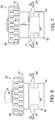
FIG. 6 is an elevation view of the tensioning member of the golf club ofFIG. 1 in an engaged condition. -
FIG. 7 is an elevation view of the tensioning member of the golf club ofFIG. 1 in a disengaged condition. -
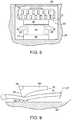
FIG. 8 is an elevation view of the tensioning member of the golf club ofFIG. 1 , shown within the body member of the club head and beneath a cover. -
FIG. 9 is an elevation view of an alternative embodiment of a tensioning member shown in an engaged condition with a tension element. -
FIG. 10 is a plan view of another aspect of a golf club head shown with a weight attached thereto. -
FIG. 11 is a plan view of another aspect of a golf club head shown with a plurality of weights attached thereto. -
FIG. 12 is a perspective view of another aspect of a golf club with a tension element and a tensioning member located at an end of the shaft of the golf club remote from the club head. -
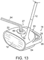
FIG. 13 is a perspective view of another aspect of a golf club with a tension element and a tensioning member, shown with a tool in use with the tensioning member. - The figures referred to above are not drawn necessarily to scale, should be understood to provide a representation of particular illustrative embodiments of the invention, and are merely conceptual in nature and illustrative of the principles involved. Some features of the golf club and golf club head with a tension element and tensioning member for securing body components together depicted in the drawings have been enlarged or distorted relative to others to facilitate explanation and understanding. The same reference numbers are used in the drawings for similar or identical components and features shown in various alternative embodiments. Golf clubs and golf club heads with a tension element and tensioning member for securing body components together as disclosed herein would have configurations and components determined, in part, by the intended application and environment in which they are used.
- An illustrative embodiment of a
golf club 10 is shown inFIG. 1 and includes ashaft 12 and agolf club head 14 attached to a first end of theshaft 12.Golf club head 14 may be any driver, wood, or the like.Shaft 12 ofgolf club 10 may be made of various materials, such as steel, aluminum, titanium, graphite, or composite materials, as well as alloys and/or combinations thereof, including materials that are conventionally known and used in the art. Additionally, theshaft 12 may be attached to theclub head 14 in any desired manner, including in conventional manners known and used in the art (e.g., via adhesives or cements at a hosel element, via fusing techniques (e.g., welding, brazing, soldering, etc.), via threads or other mechanical connectors, via friction fits, via retaining element structures, etc.). A grip orother handle element 16 is positioned onshaft 12 to provide a golfer with a slip resistant surface with which to graspgolf club shaft 12.Grip element 16 may be attached toshaft 12 in any desired manner, including in conventional manners known and used in the art (e.g., via adhesives or cements, via threads or other mechanical connectors, via fusing techniques, via friction fits, via retaining element structures, etc.). -
Club head 14 includes a plurality of components. As illustrated, this examplegolf club head 14 includes aface plate 18 and abody member 20 positioned behindface plate 18. In the illustrated embodiment,body member 20 includes acrown portion 22, asole portion 24, and askirt 26 positioned (e.g., extending) rearwardly fromcrown portion 22 andsole portion 24. It is to be appreciated thatclub head 14 may include any number of components. -
Body member 20 ofgolf club head 14 may be constructed from a wide variety of different materials, including materials conventionally known and used in the art, such as steel, titanium, aluminum, magnesium, nickel, tungsten, alloys of these metals, graphite, polymers, fiber-reinforced materials, or composites, or combinations thereof. Other suitable materials will become readily apparent to those skilled in the art, given the benefit of this disclosure. It is to be appreciated thatcrown portion 22 andsole portion 24 may be formed of the same or different material. - The component elements of
club head 14 are releasably secured to one another with atensioning assembly 27 that includes atension element 28 and a tensioningmember 30. The use of tensioningassembly 27 allows a user or other individual to quickly and easily assemble the component parts ofgolf club head 14. Thus, for example, a user could be fitted in a shop for a golf club head that is optimized for their swing, and have that club assembled while in the shop. Once the user's swing has been evaluated and the desired components of the club head have been selected, the use of tensioningassembly 27 allows the components ofclub head 14 to be quickly assembled and releasably secured together. - Advantageously, the use of tensioning
assembly 27 allowsclub head 14 to be disassembled at some future time, which allows for additional components to be added toclub head 14, such as weights, for example, or for select components ofclub head 14 to be replaced with other components. Thus, it is possible to perform routine maintenance on aclub head 14; as components ofclub head 14 experience fatigue or other performance degradation they can be quickly and easily replaced with other components. - As seen more clearly in
FIG. 2 ,tension element 28 connectsface plate 18 tobody member 20.Tension element 28 has the ability to provide tension, which allows the components ofclub head 14 to be releasably and securely fastened to one another.Tension element 28 is a cable, cord, rope, wire, fiber, ribbon, chain or filament. -
Tension element 28 engages (e.g., extends through, or is laced through) retaining members provided on the various components ofclub head 14. In the illustrated element, the face plate retaining members onface plate 18 are a pair ofhooks 32, which are provided on a rear surface offace plate 18, as seen more clearly inFIG. 3 . As illustrated here, hooks 32 are curved or arcuate members extending outwardly from the rear surface offace plate 18.Hooks 32 may be of unitary, that is, one-piece construction withface plate 18, or they may be separate elements secured to faceplate 18 with any suitable fastening means such as welding, adhesive or the like. - It is to be appreciated that the retaining members need not be hooks, and can take any desired shape or form. For example, the retaining members could be L-shaped projections or J-shaped projections extending from
face plate 18 or any other component ofclub head 14. The retaining members serve to slidably attachtension element 28 toclub head 14. That is, the retaining members allowtension element 28 and the components ofclub head 14 to slide with respect to one another. At the same time thetension element 28 serves to releasably secure the components ofclub head 14 to one another. -
Body member 20 may also include body retaining members to receivetension element 28. The body retaining members need not be the same shape as those found onface plate 18. A body retaining member provided onskirt 26 takes on another shape, namely achannel 34.Tension element 28 extends acrosssole portion 24 ofbody member 20 and then passes throughchannel 34 formed in an upper surface ofskirt 26. Thus, it is to be appreciated that the retaining members that contact and retaintension element 28 with respect to the various components ofclub head 14 can take any desired shape or form that allowstension element 28 to connect and secure the various components ofclub head 14 to one another. - In this illustrative embodiment, tension element is not directly connected to crown
portion 22 orsole portion 24 ofbody member 20;crown portion 22 andsole portion 24 are sandwiched betweenface plate 18 andskirt 26. It is to be appreciated that in other embodiments, tension member may be in direct contact withcrown portion 22 andsole portion 24. For example, as seen inFIG. 4 ,crown portion 22 andsole portion 24 ofbody member 20 may include retaining members such ashooks 36 or any other retaining member. Thus, it is to be appreciated thattension element 28 need not contact each and every element ofclub head 14 directly in order to releasably secure all of the components ofclub head 14 together. - In the embodiment illustrated in
FIG. 2 , tension element is not directly retained by any element onsole portion 24, as noted above. In such an embodiment,crown portion 22 andsole portion 24 are connected to one another as a unit, which unit is then sandwiched betweenface plate 18 andskirt 26.Sole portion 24 andcrown portion 22 may be connected to one another in any desired manner. For example, as illustrated inFIG. 5 , aprojection 38 may be formed about a peripheral edge ofsole portion 24, and amating recess 40 may be formed in a peripheral edge ofcrown portion 22, withprojection 38 being received inrecess 40. Thus,sole portion 24 andcrown portion 22 are releasably connected or secured to one another in interlocking fashion. It is to be appreciated that in other embodiments a projection could be formed about the peripheral edge ofcrown portion 22 with the mating recess being formed about the peripheral edge ofsole portion 24. - As noted above, tensioning
member 30 serves to provide tension intension element 28, thereby reliably and securely fastening the components ofclub head 14 to one another. In the illustrated embodiment, tensioningmember 30, as seen inFIG. 6 in an engaged condition, is a ratchetingassembly 42 which operates in known fashion to tightentension element 28, thereby firmly securing the components ofclub head 14 to one another. - Ratcheting
assembly 42 includes abase portion 44 within which aspool 45 and ratcheting mechanism (not shown) is positioned. In the engaged condition of ratchetingassembly 42 shown inFIG. 6 , the ends oftension element 28 are wrapped aboutspool 45 in known fashion asknob 46 is rotated by the user (clockwise in the direction of arrow A in the illustrated embodiment). Asknob 46 rotates, the ends oftension element 28 move in the direction of arrows B into ratchetingassembly 42 and the opposed ends oftension element 28 are wound aboutspool 45, thereby shortening the portion oftension element 28 outside ratchetingassembly 42 and, consequently, increasing the tension intension element 28 and securing the elements ofclub head 14 to one another. - To release the tension in ratcheting
assembly 42, as illustrated inFIG. 7 ,knob 46 is lifted upwardly in the direction of arrow C to the disengaged condition, which releases the engagement of the ratcheting mechanism in ratchetingassembly 42, allowing the ends oftension element 28 to spin off ofspool 45 and move outwardly from ratchetingassembly 42 in the direction of arrows D, thereby releasing the tension intension element 28 and allowingclub head 14 to be disassembled. A more detailed discussion of the internal operation of exemplary ratcheting assemblies is found inU.S. Patent Nos. 5,934,599 ;6,202,953 ; and6,289,558 , the entire disclosures of which are incorporated herein by reference in their entireties. - It is to be appreciated that in certain embodiments, tensioning
element 30 is resistant to creep strain, thereby ensuring that the components ofclub head 14 remain securely attached to one another despite the rapid swinging ofgolf club 10 and repeated impacts ofclub head 14 with golf balls. - In certain embodiments, as illustrated in
FIG. 1 , tensioningmember 30 is visible from the exterior ofclub head 14. In other embodiments, tensioningmember 30 may be concealed withinclub head 14. For example, as illustrated inFIG. 8 , acover 48 is provided in anopening 50 formed in an upper surface ofcrown portion 24, thereby reducing the infiltration of dirt and debris into tensioningmember 30.Cover 48 may be secured within opening 50 in known snap-fit fashion or the like. Either ofcover 48 oropening 50 may have one or more tabs or other suitable projections that are received in corresponding slots or other suitable apertures in the other ofcover 48 andopening 50 in order to securecover 48 in its desired position. Other means of securingcover 48 will become readily apparent to those skilled in the art, given the benefit of this disclosure. - It is to be appreciated that tensioning
member 30 may take other forms in addition to the ratcheting assembly discussed above. For example, as seen inFIG. 9 , tensioningmember 30 may be acam mechanism 52 including acam lever 54 that pivots about ashaft 56, pinchingtension elements 28 against a surface ofbody member 20.Body member 20 may includeteeth 58 extending outwardly from its surface to help engagetension elements 28. - It is to be appreciated that any type of cam mechanism or any other tensioning member may be used that will provide tension to
tension elements 28, thereby allowing the component parts ofclub head 14 to be firmly, reliably, and releasably secured to one another. Other suitable tensioning members will become readily apparent to those skilled in the art, given the benefit of this disclosure. - In certain embodiments, additional components can be added to
club head 14. For example, as illustrated inFIG. 10 , anadditional weight 60 can be releasably secured to the other components ofclub head 14 by way oftension element 28. In the illustrated embodiment,club head 14 is shown withoutskirt 16 and withweight 60 positioned along the rear surface ofbody member 20, withtension element 28 engaged by retainingmembers 62 onweight 60. It is to be appreciated thatweight 60 can be positioned at any location onclub head 14, including being positioned within the interior ofbody member 20. - It is also to be appreciated that more than one
weight 60 can be secured toclub head 14. For example, as illustrated inFIG. 11 , threeweights 60 are positioned along the rear surface ofclub head 14. Any number ofweights 60 can be included inclub head 14, and eachweight 60 can be positioned at any desired location withinclub head 14. - Since
club head 14 can be quickly and easily assembled and disassembled through the use of tensioningassembly 27, the component parts ofclub head 14 can be quickly and easily interchanged or replaced with other components. Accordingly, a user can have a variety of different club head components that can be substituted for one another for a variety of reasons. For example, a club component can be selected based on playing conditions expected to be encountered (e.g., different course conditions, different weather conditions, different wind conditions, etc.), the type of golf ball being used, and the skill or ability of the golfer. As a user improves, they may adapt a different playing style, and being able to replace the club head component allows them to modify their club without purchasing an entirely new club. It is to be appreciated that all aspects of the geometry or mass properties ofclub head 14 can be modified through the use of the interchangeable club head components including, but not limited to, the club head's shape, weight, weight distribution, bounce angle, center of gravity, moment of inertia, material of which it is formed, and appearance, which can alter the center of gravity, moment of inertia, and/or other "feel" characteristics ofclub head 14. - As noted above, tensioning
member 30 can be positioned at any location withingolf club 10. In certain embodiments, as illustrated inFIG. 12 , tensioningmember 30 is positioned at a second end ofshaft 12, remote fromclub head 14. In this embodiment,tension element 28 engages (e.g., is wound or laced through) the components ofclub head 14 and then extends upwardly throughshaft 12 to tensioningmember 30 at the end ofshaft 12. - Yet another embodiment is shown in
FIG. 13 , in which atool 64 is used to facilitate turning ofknob 46 of tensioningmember 30.Tool 64, which may be a hex head wrench for example, provides additional leverage for turningknob 46, thereby increasing the ability of the user to provide a high level of tension intension element 28. This can help ensure that the components ofclub head 14 are securely fastened together. In certain embodiments,tool 64 may be a torque wrench or other torque limiting tool that tensioningmember 30 imparts the proper amount of tension totension element 28. - Thus, while there have been shown, described, and pointed out fundamental novel features of various embodiments, it will be understood that various omissions, substitutions, and changes in the form and details of the devices illustrated, and in their operation, may be made by those skilled in the art without departing from the scope of the invention as defined by the claims appended hereto. It is the intention, therefore, to be limited only by the scope of the claims appended hereto.
Claims (15)
- A golf club head (14) comprising:a face plate (18) including at least one face plate retaining member;a body member (20) positioned rearwardly of the face plate and having at least one body retaining member; anda tensioning assembly (27) comprising a tension element (28) and a tensioning member (30) connected to the tension element, wherein the tension element is a cable, cord, rope, wire, fiber, ribbon, chain or filament, and the tension element engages the face plate and body member retaining members to releasably secure the face plate to the body member.
- The golf club head of claim 1, wherein the body member comprises:a crown portion;a sole portion positioned beneath the crown portion; anda skirt extending rearwardly from the crown portion and the sole portion.
- The golf club head of claim 2, wherein the skirt includes a channel through which the tension element extends.
- The golf club head of claim 2, further comprising at least one weight releasably secured to the club head by the tensioning assembly.
- The golf club head of claim 2, wherein the crown portion and the sole portion are sandwiched between the skirt and the face plate.
- The golf club head of claim 1, wherein the face plate includes a pair of retaining members on a rear surface thereof.
- The golf club head of claim 1, wherein at least a portion of the tensioning member is positioned in the body member.
- The golf club head of claim 1, wherein the tensioning member includes a spool about which the tension element is wound.
- The golf club head of claim 1, wherein the tensioning member includes a ratcheting assembly.
- The golf club head of claim 1, wherein the tensioning member includes a cam mechanism.
- The golf club head of claim 1, wherein the tension element is a cable.
- The golf club head of claim 1, further comprising a tool for use with the tensioning member to increase tension in the tension element.
- A golf club assembly comprising:a shaft having a first end and a second end; anda golf club head of any one of claims 1 to 12 secured to the first end of the shaft.
- The golf club assembly of claim 13, wherein at least a portion of the tensioning member is positioned in the club head.
- The golf club assembly of claim 13, wherein the tensioning member is positioned at the second end of the shaft.
Applications Claiming Priority (2)
| Application Number | Priority Date | Filing Date | Title |
|---|---|---|---|
| US12/205,301 US7871334B2 (en) | 2008-09-05 | 2008-09-05 | Golf club head and golf club with tension element and tensioning member |
| PCT/US2009/055845 WO2010028118A2 (en) | 2008-09-05 | 2009-09-03 | Golf club head and golf club with tension element and tensioning member |
Publications (2)
| Publication Number | Publication Date |
|---|---|
| EP2331216A2 EP2331216A2 (en) | 2011-06-15 |
| EP2331216B1 true EP2331216B1 (en) | 2018-06-13 |
Family
ID=41797845
Family Applications (1)
| Application Number | Title | Priority Date | Filing Date |
|---|---|---|---|
| EP09792215.7A Not-in-force EP2331216B1 (en) | 2008-09-05 | 2009-09-03 | Golf club head and golf club with tension element and tensioning member |
Country Status (5)
| Country | Link |
|---|---|
| US (2) | US7871334B2 (en) |
| EP (1) | EP2331216B1 (en) |
| JP (1) | JP5468610B2 (en) |
| CN (1) | CN102137696B (en) |
| WO (1) | WO2010028118A2 (en) |
Families Citing this family (60)
| Publication number | Priority date | Publication date | Assignee | Title |
|---|---|---|---|---|
| US20060156517A1 (en) | 1997-08-22 | 2006-07-20 | Hammerslag Gary R | Reel based closure system |
| CN101193568B (en) | 2004-10-29 | 2011-11-30 | 博技术有限公司 | Roll-based closure system and article of footwear using same |
| US9700764B2 (en) * | 2006-08-03 | 2017-07-11 | Vandette B. Carter | Golf club with adjustable center of gravity head |
| EP2076224B1 (en) | 2006-09-12 | 2016-08-24 | Boa Technology, Inc. | Closure system for braces, protective wear and similar articles |
| EP2237692B1 (en) | 2008-01-18 | 2015-01-07 | Boa Technology, Inc. | Closure system |
| EP2378911B1 (en) | 2008-11-21 | 2014-05-21 | Boa Technology, Inc. | Reel based lacing system |
| US20110028238A1 (en) * | 2009-07-31 | 2011-02-03 | Nike, Inc. | Golf Club With Non-Metallic Fasteners |
| US8206243B2 (en) * | 2009-08-26 | 2012-06-26 | Nike, Inc. | Golf clubs and golf club heads having a movable weight |
| WO2011091325A1 (en) | 2010-01-21 | 2011-07-28 | Boa Technology, Inc. | Guides for lacing systems |
| US9375053B2 (en) | 2012-03-15 | 2016-06-28 | Boa Technology, Inc. | Tightening mechanisms and applications including the same |
| KR102269934B1 (en) | 2010-04-30 | 2021-06-25 | 보아 테크놀러지, 인크. | Reel based lacing system |
| US10070695B2 (en) | 2010-04-30 | 2018-09-11 | Boa Technology Inc. | Tightening mechanisms and applications including the same |
| WO2012003399A2 (en) | 2010-07-01 | 2012-01-05 | Boa Technology, Inc. | Lace guide |
| US9101181B2 (en) | 2011-10-13 | 2015-08-11 | Boa Technology Inc. | Reel-based lacing system |
| US9179729B2 (en) | 2012-03-13 | 2015-11-10 | Boa Technology, Inc. | Tightening systems |
| US9532893B2 (en) | 2012-08-31 | 2017-01-03 | Nike, Inc. | Motorized tensioning system |
| US9516923B2 (en) | 2012-11-02 | 2016-12-13 | Boa Technology Inc. | Coupling members for closure devices and systems |
| EP2916680B1 (en) | 2012-11-06 | 2018-12-26 | Boa Technology Inc. | Devices and methods for adjusting the fit of footwear |
| EP2948014B1 (en) | 2013-01-28 | 2019-06-26 | Boa Technology Inc. | Lace fixation assembly and system |
| WO2014124054A1 (en) | 2013-02-05 | 2014-08-14 | Boa Technology Inc. | Closure devices for medical devices and methods |
| US9610185B2 (en) | 2013-03-05 | 2017-04-04 | Boa Technology Inc. | Systems, methods, and devices for automatic closure of medical devices |
| US10251451B2 (en) | 2013-03-05 | 2019-04-09 | Boa Technology Inc. | Closure devices including incremental release mechanisms and methods therefor |
| KR20260030757A (en) | 2013-04-01 | 2026-03-06 | 보아 테크놀러지, 인크. | Methods and devices for retrofitting footwear to include a reel based closure system |
| PL4427621T3 (en) | 2013-06-05 | 2026-03-16 | Boa Technology Inc. | COMPONENTS AND METHODS RELATED TO INTEGRATED LOCKING DEVICES |
| US10076160B2 (en) | 2013-06-05 | 2018-09-18 | Boa Technology Inc. | Integrated closure device components and methods |
| US9629417B2 (en) | 2013-07-02 | 2017-04-25 | Boa Technology Inc. | Tension limiting mechanisms for closure devices and methods therefor |
| EP3019043B1 (en) | 2013-07-10 | 2019-09-18 | Boa Technology Inc. | Closure devices including incremental release mechanisms and methods therefor |
| WO2015035257A2 (en) | 2013-09-05 | 2015-03-12 | Boa Technology Inc. | Alternative lacing guides for tightening mechanisms and methods therefor |
| KR102350912B1 (en) | 2013-09-13 | 2022-01-13 | 보아 테크놀러지, 인크. | Reel based closure device and method therefore |
| KR101895140B1 (en) | 2013-11-18 | 2018-09-04 | 보아 테크놀러지, 인크. | Methods and devices for providing automatic closure of prosthetics and orthotics |
| USD835976S1 (en) | 2014-01-16 | 2018-12-18 | Boa Technology Inc. | Coupling member |
| USD751281S1 (en) | 2014-08-12 | 2016-03-15 | Boa Technology, Inc. | Footwear tightening reels |
| USD767269S1 (en) | 2014-08-26 | 2016-09-27 | Boa Technology Inc. | Footwear tightening reel |
| US20160058127A1 (en) | 2014-08-28 | 2016-03-03 | Boa Technology Inc. | Devices and methods for enhancing the fit of boots and other footwear |
| USD758061S1 (en) | 2014-09-08 | 2016-06-07 | Boa Technology, Inc. | Lace tightening device |
| WO2016054317A1 (en) | 2014-10-01 | 2016-04-07 | Ossur Hf | Support for articles and methods for using the same |
| WO2016057697A1 (en) | 2014-10-07 | 2016-04-14 | Boa Technology Inc. | A tension adjustment mechanism and a method for adjusting the fit of a shoe |
| USD835898S1 (en) | 2015-01-16 | 2018-12-18 | Boa Technology Inc. | Footwear lace tightening reel stabilizer |
| USD776421S1 (en) | 2015-01-16 | 2017-01-17 | Boa Technology, Inc. | In-footwear lace tightening reel |
| US10004297B2 (en) | 2015-10-15 | 2018-06-26 | Boa Technology Inc. | Lacing configurations for footwear |
| US10071293B2 (en) * | 2015-11-12 | 2018-09-11 | Green Golf LLC | Golf putter heads |
| US10556161B2 (en) | 2016-05-25 | 2020-02-11 | Karsten Manufacturing Corporation | Adjustable weight club head |
| JP7073335B2 (en) | 2016-08-02 | 2022-05-23 | ボア テクノロジー,インコーポレイテッド | Tension member guide for string tightening system |
| KR102822775B1 (en) | 2016-12-09 | 2025-06-20 | 보아 테크놀러지, 인크. | Reel based closure system |
| US10543630B2 (en) | 2017-02-27 | 2020-01-28 | Boa Technology Inc. | Reel based closure system employing a friction based tension mechanism |
| US11357279B2 (en) | 2017-05-09 | 2022-06-14 | Boa Technology Inc. | Closure components for a helmet layer and methods for installing same |
| US10772384B2 (en) | 2017-07-18 | 2020-09-15 | Boa Technology Inc. | System and methods for minimizing dynamic lace movement |
| US12396520B2 (en) | 2017-07-18 | 2025-08-26 | Boa Technology Inc. | Configurations for footwear employing reel based closure systems |
| US20220387864A1 (en) * | 2018-05-25 | 2022-12-08 | Parsons Xtreme Golf, LLC | Golf club heads and methods to manufacture golf club heads |
| EP4678055A3 (en) | 2019-02-01 | 2026-04-15 | Boa Technology, Inc. | Reel based closure devices for tightening a ski boot |
| CN114072024B (en) | 2019-05-01 | 2024-08-20 | Boa科技股份有限公司 | Reel-based closure system |
| US12576315B2 (en) * | 2019-05-10 | 2026-03-17 | Taylor Made Golf Company, Inc. | Clubheads for iron-type golf clubs |
| US11400351B2 (en) | 2019-05-10 | 2022-08-02 | Taylor Made Golf Company, Inc. | Golf club |
| US11351429B2 (en) | 2019-05-10 | 2022-06-07 | Taylor Made Golf Company, Inc. | Golf club |
| US11458374B2 (en) * | 2019-05-10 | 2022-10-04 | Taylor Made Golf Company, Inc. | Golf club |
| US11413510B2 (en) * | 2019-05-10 | 2022-08-16 | Taylor Made Golf Company, Inc. | Golf club |
| US11406882B2 (en) * | 2019-05-10 | 2022-08-09 | Taylor Made Golf Company, Inc. | Iron-type golf club head |
| US10512826B1 (en) * | 2019-05-21 | 2019-12-24 | Callaway Golf Company | Golf club head with structural tension cable |
| EP4223368B1 (en) | 2020-09-30 | 2025-05-21 | Asahi Kasei Pharma Corporation | Macrocyclic compounds incorporating piperidine and quinoline or qunaxoline as irak-4 inhibitors for the treatment of inflammatory conditions |
| JP7703868B2 (en) * | 2021-03-15 | 2025-07-08 | 住友ゴム工業株式会社 | Golf Club Head |
Citations (1)
| Publication number | Priority date | Publication date | Assignee | Title |
|---|---|---|---|---|
| US2175598A (en) * | 1938-09-27 | 1939-10-10 | Fedak Malcolm | Adjustable golf club head |
Family Cites Families (39)
| Publication number | Priority date | Publication date | Assignee | Title |
|---|---|---|---|---|
| US890836A (en) * | 1906-11-28 | 1908-06-16 | Harold Beale | Golf-club. |
| US1558703A (en) | 1924-06-10 | 1925-10-27 | Arnold W Miller | Golf club |
| US2201638A (en) | 1938-12-07 | 1940-05-21 | Sr Albert K Theibault | Golf club |
| US3190651A (en) | 1962-09-10 | 1965-06-22 | Albert E W Thomas | Golf club including detachable ball striking faces of various lofts |
| US3516674A (en) | 1967-12-28 | 1970-06-23 | James Anthony Scarborough | Golf putter |
| US3893670A (en) | 1973-11-02 | 1975-07-08 | Franco Franchi | Golf club with interchangeable heads |
| US4685682A (en) | 1985-06-10 | 1987-08-11 | Isabell James T | Adjustable flex golf club |
| JPH076919Y2 (en) * | 1989-10-17 | 1995-02-22 | 建夫 中島 | Golf club |
| US5011153A (en) * | 1990-07-13 | 1991-04-30 | Watkins Thomas H | Golf putting aid and teaching device |
| US5316304A (en) * | 1993-01-04 | 1994-05-31 | Yost David A | Wire faced golf putter |
| US5478075A (en) | 1994-06-27 | 1995-12-26 | Saia; Carman R. | Golf club stabilizer |
| US5505453A (en) * | 1994-07-20 | 1996-04-09 | Mack; Thomas E. | Tunable golf club head and method of making |
| US5470071A (en) * | 1994-09-16 | 1995-11-28 | Hsu; Kevin | Golf swing training device |
| US5464211A (en) * | 1994-09-19 | 1995-11-07 | Atkins, Sr.; Clyde | Golf club head |
| US5501453A (en) * | 1995-01-27 | 1996-03-26 | Stokes & Co., Inc. | Pretensioned golf club head |
| US5632693A (en) | 1995-11-07 | 1997-05-27 | Painter; Paul W. | Golf club having selectively adjustable internal pressure |
| US5597362A (en) | 1996-05-21 | 1997-01-28 | Lee; Young J. | Interchangeable and adjustable putter |
| US5643109A (en) * | 1996-06-10 | 1997-07-01 | Rose; Arthur S. | Tensioned band golf putter head |
| US5899819A (en) | 1997-05-14 | 1999-05-04 | Mount; Gregory T. | Golf putter |
| US5931746A (en) * | 1997-05-21 | 1999-08-03 | Soong; Tsai C. | Golf club head having a tensile pre-stressed face plate |
| US5934599A (en) | 1997-08-22 | 1999-08-10 | Hammerslag; Gary R. | Footwear lacing system |
| US6289558B1 (en) | 1997-08-22 | 2001-09-18 | Boa Technology, Inc. | Footwear lacing system |
| US6361451B1 (en) | 1998-09-21 | 2002-03-26 | Mide Technology Corporation | Variable stiffness shaft |
| NO308156B1 (en) | 1998-10-23 | 2000-08-07 | Jon Klyve | Device by golf club of the "putter" type |
| US6203444B1 (en) * | 1999-07-03 | 2001-03-20 | Mcrae Brian J. | Golf putter having a negatively contoured ball-striking surface |
| US6394909B1 (en) | 1999-12-15 | 2002-05-28 | Charnnarong Laibangyang | Golf club with fixed-tension shaft |
| US20020128093A1 (en) | 2001-01-23 | 2002-09-12 | Whayne James G. | Athletic equipment with improved force respones |
| NO314982B1 (en) | 2001-03-29 | 2003-06-23 | Clyve As | Golf putter head and interchangeable cartridge head for golf putter head |
| US20030017884A1 (en) | 2001-03-30 | 2003-01-23 | Masters Brett P. | Golf club shaft with superelastic tensioning device |
| ITMI20010938A1 (en) | 2001-05-08 | 2002-11-08 | Itw Ind Components Srl | CAM CABLE CLAMP |
| US6524197B2 (en) * | 2001-05-11 | 2003-02-25 | Zevo Golf | Golf club head having a device for resisting expansion between opposing walls during ball impact |
| US6682439B2 (en) | 2001-08-01 | 2004-01-27 | Dennis E. Brown | Multi-string putter face with separate and variable tension capabilities and multiple position shaft with adjustable shaft angle capabilities |
| US6672975B1 (en) * | 2003-02-06 | 2004-01-06 | Callaway Golf Company | Golf club head |
| US20050054461A1 (en) * | 2003-09-10 | 2005-03-10 | Seree Pakarnseree | Golf club head with springy striking area |
| JP3888989B2 (en) * | 2003-10-06 | 2007-03-07 | ペパーレット株式会社 | Golf club head |
| US7354355B2 (en) | 2004-10-01 | 2008-04-08 | Nike, Inc. | Golf club head or other ball striking device with modifiable feel characteristics |
| US7147573B2 (en) | 2005-02-07 | 2006-12-12 | Callaway Golf Company | Golf club head with adjustable weighting |
| US7303489B2 (en) * | 2005-08-18 | 2007-12-04 | Acushnet Company | Golf club |
| KR100843954B1 (en) * | 2007-12-31 | 2008-07-03 | 윤창선 | Head for golf putter |
-
2008
- 2008-09-05 US US12/205,301 patent/US7871334B2/en active Active
-
2009
- 2009-09-03 WO PCT/US2009/055845 patent/WO2010028118A2/en not_active Ceased
- 2009-09-03 JP JP2011526186A patent/JP5468610B2/en not_active Expired - Fee Related
- 2009-09-03 EP EP09792215.7A patent/EP2331216B1/en not_active Not-in-force
- 2009-09-03 CN CN200980134254XA patent/CN102137696B/en not_active Expired - Fee Related
-
2010
- 2010-05-20 US US12/783,998 patent/US7871335B2/en active Active
Patent Citations (1)
| Publication number | Priority date | Publication date | Assignee | Title |
|---|---|---|---|---|
| US2175598A (en) * | 1938-09-27 | 1939-10-10 | Fedak Malcolm | Adjustable golf club head |
Also Published As
| Publication number | Publication date |
|---|---|
| CN102137696A (en) | 2011-07-27 |
| WO2010028118A3 (en) | 2010-06-17 |
| US20100062874A1 (en) | 2010-03-11 |
| CN102137696B (en) | 2013-05-01 |
| JP5468610B2 (en) | 2014-04-09 |
| US20100227701A1 (en) | 2010-09-09 |
| JP2012501746A (en) | 2012-01-26 |
| US7871334B2 (en) | 2011-01-18 |
| WO2010028118A2 (en) | 2010-03-11 |
| EP2331216A2 (en) | 2011-06-15 |
| US7871335B2 (en) | 2011-01-18 |
Similar Documents
| Publication | Publication Date | Title |
|---|---|---|
| US7871334B2 (en) | Golf club head and golf club with tension element and tensioning member | |
| US7922603B2 (en) | Golf club assembly and golf club head with bar and weighted member | |
| US7878919B2 (en) | Golf club head and golf club assembly with fastener | |
| US8133129B2 (en) | Golf club and golf club head with interchangeable body component | |
| JP3132741U (en) | Golf club to prevent hooks and slices | |
| US9168438B2 (en) | Golf club and golf club head structures | |
| US7611424B2 (en) | Golf club head and golf club | |
| JP5628686B2 (en) | Golf club and golf club head with adjustable center of gravity and moment of inertia characteristics | |
| JP5551784B2 (en) | Golf club and golf club head with adjustable center of gravity and moment of inertia characteristics | |
| JP5869499B2 (en) | Golf club and golf club head including structure for selectively controlling sound of club head | |
| US20120149488A1 (en) | Golf club hosel | |
| US5647806A (en) | Dual shaft golf club | |
| US7625297B1 (en) | Golf club shaft with adjustable stiffness |
Legal Events
| Date | Code | Title | Description |
|---|---|---|---|
| PUAI | Public reference made under article 153(3) epc to a published international application that has entered the european phase |
Free format text: ORIGINAL CODE: 0009012 |
|
| 17P | Request for examination filed |
Effective date: 20110222 |
|
| AK | Designated contracting states |
Kind code of ref document: A2 Designated state(s): AT BE BG CH CY CZ DE DK EE ES FI FR GB GR HR HU IE IS IT LI LT LU LV MC MK MT NL NO PL PT RO SE SI SK SM TR |
|
| AX | Request for extension of the european patent |
Extension state: AL BA RS |
|
| DAX | Request for extension of the european patent (deleted) | ||
| 17Q | First examination report despatched |
Effective date: 20131008 |
|
| RAP1 | Party data changed (applicant data changed or rights of an application transferred) |
Owner name: NIKE INNOVATE C.V. |
|
| GRAP | Despatch of communication of intention to grant a patent |
Free format text: ORIGINAL CODE: EPIDOSNIGR1 |
|
| STAA | Information on the status of an ep patent application or granted ep patent |
Free format text: STATUS: GRANT OF PATENT IS INTENDED |
|
| INTG | Intention to grant announced |
Effective date: 20180103 |
|
| GRAS | Grant fee paid |
Free format text: ORIGINAL CODE: EPIDOSNIGR3 |
|
| GRAA | (expected) grant |
Free format text: ORIGINAL CODE: 0009210 |
|
| STAA | Information on the status of an ep patent application or granted ep patent |
Free format text: STATUS: THE PATENT HAS BEEN GRANTED |
|
| AK | Designated contracting states |
Kind code of ref document: B1 Designated state(s): AT BE BG CH CY CZ DE DK EE ES FI FR GB GR HR HU IE IS IT LI LT LU LV MC MK MT NL NO PL PT RO SE SI SK SM TR |
|
| REG | Reference to a national code |
Ref country code: GB Ref legal event code: FG4D |
|
| REG | Reference to a national code |
Ref country code: CH Ref legal event code: EP Ref country code: AT Ref legal event code: REF Ref document number: 1007864 Country of ref document: AT Kind code of ref document: T Effective date: 20180615 |
|
| REG | Reference to a national code |
Ref country code: IE Ref legal event code: FG4D |
|
| REG | Reference to a national code |
Ref country code: DE Ref legal event code: R096 Ref document number: 602009052791 Country of ref document: DE |
|
| REG | Reference to a national code |
Ref country code: NL Ref legal event code: MP Effective date: 20180613 |
|
| REG | Reference to a national code |
Ref country code: LT Ref legal event code: MG4D |
|
| PG25 | Lapsed in a contracting state [announced via postgrant information from national office to epo] |
Ref country code: CY Free format text: LAPSE BECAUSE OF FAILURE TO SUBMIT A TRANSLATION OF THE DESCRIPTION OR TO PAY THE FEE WITHIN THE PRESCRIBED TIME-LIMIT Effective date: 20180613 Ref country code: NO Free format text: LAPSE BECAUSE OF FAILURE TO SUBMIT A TRANSLATION OF THE DESCRIPTION OR TO PAY THE FEE WITHIN THE PRESCRIBED TIME-LIMIT Effective date: 20180913 Ref country code: SE Free format text: LAPSE BECAUSE OF FAILURE TO SUBMIT A TRANSLATION OF THE DESCRIPTION OR TO PAY THE FEE WITHIN THE PRESCRIBED TIME-LIMIT Effective date: 20180613 Ref country code: FI Free format text: LAPSE BECAUSE OF FAILURE TO SUBMIT A TRANSLATION OF THE DESCRIPTION OR TO PAY THE FEE WITHIN THE PRESCRIBED TIME-LIMIT Effective date: 20180613 Ref country code: BG Free format text: LAPSE BECAUSE OF FAILURE TO SUBMIT A TRANSLATION OF THE DESCRIPTION OR TO PAY THE FEE WITHIN THE PRESCRIBED TIME-LIMIT Effective date: 20180913 Ref country code: ES Free format text: LAPSE BECAUSE OF FAILURE TO SUBMIT A TRANSLATION OF THE DESCRIPTION OR TO PAY THE FEE WITHIN THE PRESCRIBED TIME-LIMIT Effective date: 20180613 Ref country code: LT Free format text: LAPSE BECAUSE OF FAILURE TO SUBMIT A TRANSLATION OF THE DESCRIPTION OR TO PAY THE FEE WITHIN THE PRESCRIBED TIME-LIMIT Effective date: 20180613 |
|
| RAP2 | Party data changed (patent owner data changed or rights of a patent transferred) |
Owner name: KARSTEN MANUFACTURING CORPORATION |
|
| PG25 | Lapsed in a contracting state [announced via postgrant information from national office to epo] |
Ref country code: LV Free format text: LAPSE BECAUSE OF FAILURE TO SUBMIT A TRANSLATION OF THE DESCRIPTION OR TO PAY THE FEE WITHIN THE PRESCRIBED TIME-LIMIT Effective date: 20180613 Ref country code: HR Free format text: LAPSE BECAUSE OF FAILURE TO SUBMIT A TRANSLATION OF THE DESCRIPTION OR TO PAY THE FEE WITHIN THE PRESCRIBED TIME-LIMIT Effective date: 20180613 Ref country code: GR Free format text: LAPSE BECAUSE OF FAILURE TO SUBMIT A TRANSLATION OF THE DESCRIPTION OR TO PAY THE FEE WITHIN THE PRESCRIBED TIME-LIMIT Effective date: 20180914 |
|
| REG | Reference to a national code |
Ref country code: GB Ref legal event code: 732E Free format text: REGISTERED BETWEEN 20181115 AND 20181130 |
|
| REG | Reference to a national code |
Ref country code: AT Ref legal event code: MK05 Ref document number: 1007864 Country of ref document: AT Kind code of ref document: T Effective date: 20180613 |
|
| PG25 | Lapsed in a contracting state [announced via postgrant information from national office to epo] |
Ref country code: NL Free format text: LAPSE BECAUSE OF FAILURE TO SUBMIT A TRANSLATION OF THE DESCRIPTION OR TO PAY THE FEE WITHIN THE PRESCRIBED TIME-LIMIT Effective date: 20180613 |
|
| PG25 | Lapsed in a contracting state [announced via postgrant information from national office to epo] |
Ref country code: AT Free format text: LAPSE BECAUSE OF FAILURE TO SUBMIT A TRANSLATION OF THE DESCRIPTION OR TO PAY THE FEE WITHIN THE PRESCRIBED TIME-LIMIT Effective date: 20180613 Ref country code: PL Free format text: LAPSE BECAUSE OF FAILURE TO SUBMIT A TRANSLATION OF THE DESCRIPTION OR TO PAY THE FEE WITHIN THE PRESCRIBED TIME-LIMIT Effective date: 20180613 Ref country code: IS Free format text: LAPSE BECAUSE OF FAILURE TO SUBMIT A TRANSLATION OF THE DESCRIPTION OR TO PAY THE FEE WITHIN THE PRESCRIBED TIME-LIMIT Effective date: 20181013 Ref country code: EE Free format text: LAPSE BECAUSE OF FAILURE TO SUBMIT A TRANSLATION OF THE DESCRIPTION OR TO PAY THE FEE WITHIN THE PRESCRIBED TIME-LIMIT Effective date: 20180613 Ref country code: CZ Free format text: LAPSE BECAUSE OF FAILURE TO SUBMIT A TRANSLATION OF THE DESCRIPTION OR TO PAY THE FEE WITHIN THE PRESCRIBED TIME-LIMIT Effective date: 20180613 Ref country code: RO Free format text: LAPSE BECAUSE OF FAILURE TO SUBMIT A TRANSLATION OF THE DESCRIPTION OR TO PAY THE FEE WITHIN THE PRESCRIBED TIME-LIMIT Effective date: 20180613 Ref country code: SK Free format text: LAPSE BECAUSE OF FAILURE TO SUBMIT A TRANSLATION OF THE DESCRIPTION OR TO PAY THE FEE WITHIN THE PRESCRIBED TIME-LIMIT Effective date: 20180613 |
|
| PG25 | Lapsed in a contracting state [announced via postgrant information from national office to epo] |
Ref country code: SM Free format text: LAPSE BECAUSE OF FAILURE TO SUBMIT A TRANSLATION OF THE DESCRIPTION OR TO PAY THE FEE WITHIN THE PRESCRIBED TIME-LIMIT Effective date: 20180613 Ref country code: IT Free format text: LAPSE BECAUSE OF FAILURE TO SUBMIT A TRANSLATION OF THE DESCRIPTION OR TO PAY THE FEE WITHIN THE PRESCRIBED TIME-LIMIT Effective date: 20180613 |
|
| REG | Reference to a national code |
Ref country code: DE Ref legal event code: R097 Ref document number: 602009052791 Country of ref document: DE |
|
| REG | Reference to a national code |
Ref country code: DE Ref legal event code: R119 Ref document number: 602009052791 Country of ref document: DE |
|
| PLBE | No opposition filed within time limit |
Free format text: ORIGINAL CODE: 0009261 |
|
| STAA | Information on the status of an ep patent application or granted ep patent |
Free format text: STATUS: NO OPPOSITION FILED WITHIN TIME LIMIT |
|
| PG25 | Lapsed in a contracting state [announced via postgrant information from national office to epo] |
Ref country code: MC Free format text: LAPSE BECAUSE OF FAILURE TO SUBMIT A TRANSLATION OF THE DESCRIPTION OR TO PAY THE FEE WITHIN THE PRESCRIBED TIME-LIMIT Effective date: 20180613 |
|
| REG | Reference to a national code |
Ref country code: CH Ref legal event code: PL |
|
| 26N | No opposition filed |
Effective date: 20190314 |
|
| PG25 | Lapsed in a contracting state [announced via postgrant information from national office to epo] |
Ref country code: SI Free format text: LAPSE BECAUSE OF FAILURE TO SUBMIT A TRANSLATION OF THE DESCRIPTION OR TO PAY THE FEE WITHIN THE PRESCRIBED TIME-LIMIT Effective date: 20180613 Ref country code: DK Free format text: LAPSE BECAUSE OF FAILURE TO SUBMIT A TRANSLATION OF THE DESCRIPTION OR TO PAY THE FEE WITHIN THE PRESCRIBED TIME-LIMIT Effective date: 20180613 |
|
| REG | Reference to a national code |
Ref country code: BE Ref legal event code: MM Effective date: 20180930 |
|
| PG25 | Lapsed in a contracting state [announced via postgrant information from national office to epo] |
Ref country code: LU Free format text: LAPSE BECAUSE OF NON-PAYMENT OF DUE FEES Effective date: 20180903 |
|
| PG25 | Lapsed in a contracting state [announced via postgrant information from national office to epo] |
Ref country code: DE Free format text: LAPSE BECAUSE OF NON-PAYMENT OF DUE FEES Effective date: 20190402 |
|
| PG25 | Lapsed in a contracting state [announced via postgrant information from national office to epo] |
Ref country code: CH Free format text: LAPSE BECAUSE OF NON-PAYMENT OF DUE FEES Effective date: 20180930 Ref country code: BE Free format text: LAPSE BECAUSE OF NON-PAYMENT OF DUE FEES Effective date: 20180930 Ref country code: FR Free format text: LAPSE BECAUSE OF NON-PAYMENT OF DUE FEES Effective date: 20180930 Ref country code: LI Free format text: LAPSE BECAUSE OF NON-PAYMENT OF DUE FEES Effective date: 20180930 |
|
| PG25 | Lapsed in a contracting state [announced via postgrant information from national office to epo] |
Ref country code: MT Free format text: LAPSE BECAUSE OF NON-PAYMENT OF DUE FEES Effective date: 20180903 |
|
| PG25 | Lapsed in a contracting state [announced via postgrant information from national office to epo] |
Ref country code: TR Free format text: LAPSE BECAUSE OF FAILURE TO SUBMIT A TRANSLATION OF THE DESCRIPTION OR TO PAY THE FEE WITHIN THE PRESCRIBED TIME-LIMIT Effective date: 20180613 |
|
| PG25 | Lapsed in a contracting state [announced via postgrant information from national office to epo] |
Ref country code: PT Free format text: LAPSE BECAUSE OF FAILURE TO SUBMIT A TRANSLATION OF THE DESCRIPTION OR TO PAY THE FEE WITHIN THE PRESCRIBED TIME-LIMIT Effective date: 20180613 Ref country code: HU Free format text: LAPSE BECAUSE OF FAILURE TO SUBMIT A TRANSLATION OF THE DESCRIPTION OR TO PAY THE FEE WITHIN THE PRESCRIBED TIME-LIMIT; INVALID AB INITIO Effective date: 20090903 |
|
| PG25 | Lapsed in a contracting state [announced via postgrant information from national office to epo] |
Ref country code: MK Free format text: LAPSE BECAUSE OF NON-PAYMENT OF DUE FEES Effective date: 20180613 |
|
| PGFP | Annual fee paid to national office [announced via postgrant information from national office to epo] |
Ref country code: IE Payment date: 20220927 Year of fee payment: 14 Ref country code: GB Payment date: 20220927 Year of fee payment: 14 |
|
| GBPC | Gb: european patent ceased through non-payment of renewal fee |
Effective date: 20230903 |
|
| REG | Reference to a national code |
Ref country code: IE Ref legal event code: MM4A |
|
| PG25 | Lapsed in a contracting state [announced via postgrant information from national office to epo] |
Ref country code: IE Free format text: LAPSE BECAUSE OF NON-PAYMENT OF DUE FEES Effective date: 20230903 |
|
| PG25 | Lapsed in a contracting state [announced via postgrant information from national office to epo] |
Ref country code: GB Free format text: LAPSE BECAUSE OF NON-PAYMENT OF DUE FEES Effective date: 20230903 |
|
| PG25 | Lapsed in a contracting state [announced via postgrant information from national office to epo] |
Ref country code: IE Free format text: LAPSE BECAUSE OF NON-PAYMENT OF DUE FEES Effective date: 20230903 Ref country code: GB Free format text: LAPSE BECAUSE OF NON-PAYMENT OF DUE FEES Effective date: 20230903 |