EP2330750B1 - Method and apparatus for reducing power consumption in digital living network alliance (DLNA) network - Google Patents
Method and apparatus for reducing power consumption in digital living network alliance (DLNA) network Download PDFInfo
- Publication number
- EP2330750B1 EP2330750B1 EP10192624A EP10192624A EP2330750B1 EP 2330750 B1 EP2330750 B1 EP 2330750B1 EP 10192624 A EP10192624 A EP 10192624A EP 10192624 A EP10192624 A EP 10192624A EP 2330750 B1 EP2330750 B1 EP 2330750B1
- Authority
- EP
- European Patent Office
- Prior art keywords
- dmr
- dms
- media content
- network
- dlna
- Prior art date
- Legal status (The legal status is an assumption and is not a legal conclusion. Google has not performed a legal analysis and makes no representation as to the accuracy of the status listed.)
- Not-in-force
Links
Images




Classifications
-
- G—PHYSICS
- G06—COMPUTING OR CALCULATING; COUNTING
- G06F—ELECTRIC DIGITAL DATA PROCESSING
- G06F1/00—Details not covered by groups G06F3/00 - G06F13/00 and G06F21/00
- G06F1/26—Power supply means, e.g. regulation thereof
- G06F1/32—Means for saving power
- G06F1/3203—Power management, i.e. event-based initiation of a power-saving mode
- G06F1/3234—Power saving characterised by the action undertaken
-
- H—ELECTRICITY
- H04—ELECTRIC COMMUNICATION TECHNIQUE
- H04L—TRANSMISSION OF DIGITAL INFORMATION, e.g. TELEGRAPHIC COMMUNICATION
- H04L12/00—Data switching networks
- H04L12/02—Details
- H04L12/10—Current supply arrangements
-
- H—ELECTRICITY
- H04—ELECTRIC COMMUNICATION TECHNIQUE
- H04L—TRANSMISSION OF DIGITAL INFORMATION, e.g. TELEGRAPHIC COMMUNICATION
- H04L12/00—Data switching networks
- H04L12/28—Data switching networks characterised by path configuration, e.g. LAN [Local Area Networks] or WAN [Wide Area Networks]
- H04L12/2803—Home automation networks
- H04L12/2807—Exchanging configuration information on appliance services in a home automation network
- H04L12/2814—Exchanging control software or macros for controlling appliance services in a home automation network
-
- H—ELECTRICITY
- H04—ELECTRIC COMMUNICATION TECHNIQUE
- H04W—WIRELESS COMMUNICATION NETWORKS
- H04W52/00—Power management, e.g. Transmission Power Control [TPC] or power classes
- H04W52/02—Power saving arrangements
- H04W52/0209—Power saving arrangements in terminal devices
- H04W52/0251—Power saving arrangements in terminal devices using monitoring of local events, e.g. events related to user activity
- H04W52/0254—Power saving arrangements in terminal devices using monitoring of local events, e.g. events related to user activity detecting a user operation or a tactile contact or a motion of the device
-
- H—ELECTRICITY
- H04—ELECTRIC COMMUNICATION TECHNIQUE
- H04L—TRANSMISSION OF DIGITAL INFORMATION, e.g. TELEGRAPHIC COMMUNICATION
- H04L12/00—Data switching networks
- H04L12/28—Data switching networks characterised by path configuration, e.g. LAN [Local Area Networks] or WAN [Wide Area Networks]
- H04L12/2803—Home automation networks
- H04L2012/2847—Home automation networks characterised by the type of home appliance used
- H04L2012/285—Generic home appliances, e.g. refrigerators
-
- H—ELECTRICITY
- H04—ELECTRIC COMMUNICATION TECHNIQUE
- H04L—TRANSMISSION OF DIGITAL INFORMATION, e.g. TELEGRAPHIC COMMUNICATION
- H04L67/00—Network arrangements or protocols for supporting network services or applications
- H04L67/50—Network services
- H04L67/75—Indicating network or usage conditions on the user display
-
- Y—GENERAL TAGGING OF NEW TECHNOLOGICAL DEVELOPMENTS; GENERAL TAGGING OF CROSS-SECTIONAL TECHNOLOGIES SPANNING OVER SEVERAL SECTIONS OF THE IPC; TECHNICAL SUBJECTS COVERED BY FORMER USPC CROSS-REFERENCE ART COLLECTIONS [XRACs] AND DIGESTS
- Y02—TECHNOLOGIES OR APPLICATIONS FOR MITIGATION OR ADAPTATION AGAINST CLIMATE CHANGE
- Y02D—CLIMATE CHANGE MITIGATION TECHNOLOGIES IN INFORMATION AND COMMUNICATION TECHNOLOGIES [ICT], I.E. INFORMATION AND COMMUNICATION TECHNOLOGIES AIMING AT THE REDUCTION OF THEIR OWN ENERGY USE
- Y02D30/00—Reducing energy consumption in communication networks
- Y02D30/70—Reducing energy consumption in communication networks in wireless communication networks
Definitions
- the present invention relates to Digital Living Network Alliance (DLNA). More particularly, the present invention relates to a method and apparatus for reducing power consumption in a DLNA network.
- DLNA Digital Living Network Alliance
- Various devices are used in homes, such as information devices (e.g., Personal Computers (PCs)), communication devices (e.g., telephones), broadcasting devices (e.g., TVs), and Audio/Video (AV) devices (e.g., Digital Video Disks (DVDs) and digital cameras).
- information devices e.g., Personal Computers (PCs)
- communication devices e.g., telephones
- broadcasting devices e.g., TVs
- AV Audio/Video
- DVDs Digital Video Disks
- home automation has been proposed and used to automatically control such devices.
- home automation systems controlled home appliances separately by telephones or infrared rays.
- Home automation systems did not support a connection between the home appliances.
- recent development of communication technology provides a method of constructing a network between home appliances and integrating/managing the home appliances by a controller. This system is referred to as a home network system.
- the home network system connects various network home appliances (e.g., TVs, washing machines, microwave ovens, gas ranges, audios, air conditioners, and boilers), lighting, gas valves, and front doors to controllers (e.g., home gateways and home servers), and controls the connected appliances through a specific terminal (e.g., a remote controller).
- network home appliances e.g., TVs, washing machines, microwave ovens, gas ranges, audios, air conditioners, and boilers
- controllers e.g., home gateways and home servers
- a specific terminal e.g., a remote controller
- the Digital Living Network Alliance (DLNA) standard has been proposed for controlling information home appliances (e.g., TVs, Video Tape Recorders (VTRs), digital cameras, and audio systems).
- the DLNA standard focuses on sharing all the content provided from information home appliances.
- the use of the DLNA standard allows home devices to share various digital media content stored in personal devices (e.g., mobile devices or computers), thereby enabling users to enjoy the digital media content conveniently regardless of the locations and devices in homes.
- a portable device e.g., a mobile communication terminal
- a wireless local Area Network (WLAN) and a display device results in significant power consumption.
- a portable device e.g., a mobile communication terminal
- a method and apparatus for reducing power consumption in a DLNA network is desired.
- a prior art power-saving mechanism is disclosed in Dimitris N Kalofonos et al: "A Network Connectivity Power-Saving Mechanism for Mobile Devices in DLNA Home Networks", Consumer Communications and Networking Conference, 2007. CCNC 2007. 20 07 4th IEEE, IEEE, Pl, 1 January 2007, pages 645-649, ISBN: 978-1-4244-0667-8 .
- US 2008/305839 A1 discloses selective power management for a hand held host.
- An aspect of the present invention is to address at least the above-mentioned problems and/or disadvantages and to provide at least the advantages described below. Accordingly, an aspect of the present invention is to provide a method for reducing power consumption in a Digital Living Network Alliance (DLNA) network.
- DLNA Digital Living Network Alliance
- Another aspect of the present invention is to provide an apparatus for reducing power consumption in a DLNA network.
- a method for operating a digital media renderer to reduce power consumption in a DLNA network includes, receiving media content from a digital media server, and controlling the power of at least one of a communication connection device and a display according to the control state of the received media content.
- Another aspect provides a digital media renderer as defined by claim 6.
- Another aspect provides a DLNA network as defined by claim 8.
- FIG. 1 is a block diagram illustrating a Digital Living Network Alliance (DLNA) network according to an exemplary embodiment of the present invention
- FIG. 2 is a block diagram illustrating a DLNA network according to an exemplary embodiment of the present invention
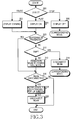
- FIG. 3 is flow diagram illustrating a method for operating a digital media renderer to reduce power consumption in a DLNA network according to an exemplary embodiment of the present invention
- FIG. 4 is flow diagram illustrating a method for operating a digital media server to reduce power consumption in a DLNA network according to an exemplary embodiment of the present invention
- FIG. 5 is flow diagram illustrating a method for operating a digital media server to reduce power consumption in a DLNA network according to another exemplary embodiment of the present invention
- FIG. 6 is flow diagram illustrating a method for operating a digital media player or a digital media renderer to reduce power consumption in a DLNA network according to an exemplary embodiment of the present invention.
- FIGs. 7A to 7G are diagrams illustrating a display screen for setting DLNA in a portable device according to an exemplary embodiment of the present invention.
- Exemplary embodiments of the present invention provide a method and apparatus for reducing power consumption in a Digital Living Network Alliance (DLNA) network.
- DLNA Digital Living Network Alliance
- FIG. 1 is a block diagram illustrating a Digital Living Network Alliance (DLNA) network according to an exemplary embodiment of the present invention.
- DLNA Digital Living Network Alliance
- a DLNA network may include a Digital Media Server (DMS) 10, a Digital Media Controller (DMC) 20, and a Digital Media Renderer (DMR) 30.
- the DMS 10, the DMC 20, and the DMR 30 may perform wired/wireless communication (e.g., using a Wireless Local Area Network (WLAN)) between them.
- the DMS 10 stores media content (e.g., moving pictures and image files). The media content may be broadcast signals received in real time.
- the DMC 20 searches the DMS 10 for media content.
- the DMC 20 requests the DMR 30 to play the corresponding media content of the DMS 10, and the DMR 30 requests the DMS 10 to provide the DMR 30 with the media content requested by the DMC 20. Thereafter, the DMS 10 transmits the corresponding media content to the DMR 30, and the DMR 30 plays the received media content.
- the DLNA network may be implemented by three component entities as described above. However, the DLNA network may also be implemented by two component entities as described below with respect to FIG. 2 .
- FIG. 2 is a block diagram illustrating a DLNA network according to an exemplary embodiment of the present invention.
- the DMP 200 may operate as the DMC 20 and the DMR 30 illustrated in FIG. 1
- the DMS 210 may be the same as the DMS 10 illustrated in FIG. 1 .
- the DMP 200 and the DMS 210 perform wired/wireless communication therebetween.
- FIG. 3 illustrates a method for operating a DMR to reduce power consumption in a DLNA network according to an exemplary embodiment of the present invention.
- An operation of the DMC 20 for reducing power consumption in the DLNA network may be the same as an operation of the DMR 30, and thus a description thereof will be omitted for conciseness.
- the DMR determines whether the operation state is a pause state, a play state or a stop state. For example, under the control of the DMC 20, the DMR 30 determines whether it is playing the content received from the DMS 10 or pauses/stops the play of the content received from the DMS 10.
- the DMR dims a display, such as a Liquid Crystal Display (LCD) to minimize the power consumption in step 302.
- LCD Liquid Crystal Display
- the DMR turns on the display to operate the display in step 304.
- the DMR continues to operate the display to display the played content.
- the DMR turns off the display to reduce the power consumption in step 306. Thereafter, the DMR proceeds to a corresponding mode. In the corresponding mode, the DMR waits for a control signal from the DMC.
- the DMR determines whether a buffering operation is in progress. The DMR determines whether it is receiving/buffering the content from the DMS. If a buffering operation is in progress (i.e., the DMR is receiving/buffering the content from the DMS in step 308), the DMR maintains a normal connection state of a WLAN in step 316 and uses the WLAN to receive/buffer the content from the DMS. If a buffering operation is not in progress (i.e., the DMR completes the reception of the content from the DMS in step 308), the DMR determines whether it operates as DMP in step 310.
- the DMR disconnects the WLAN used to transmit the content from DMS in step 314.
- the DMR powers down the WLAN to reduce the power consumption.
- the DMR reconnects the WLAN to transmit the command to the DMS.
- the DMR transitions the WLAN to a power save mode in step 312.
- the reason for transitioning the WLAN to a power save mode if the DMR does not operate as a DMP is that the DMC may transmit a control signal to the DMR even when the DMR does not receive the content from the DMS. Also, it is to maintain a power save mode of the WLAN in the play state after completion of the buffering operation.
- step 316 the DMR determines whether the DMR or the DMS disconnects from the WLAN (e.g., if a WLAN connection is difficult to maintain due to an increase in the distance from the DMR or the DMS). If the DMR or the DMS disconnects from the WLAN in step 316, the DMR notifies the user of the WLAN state through a pop-up window if the DMR is in a play state or a pause state in step 318. In step 320, the DMR disconnects the WLAN to reduce the power consumption, if a predetermined time elapses without roaming.
- the DMR continues to supply power to the WLAN or to maintain the power save mode.
- FIG. 4 illustrates a method for operating a DMS to reduce power consumption in a DLNA network according to an exemplary embodiment of the present invention.
- step 400 the DMS determines whether there is a user operation. If there is no user operation in step 400, then in step 402, regardless of the state of the DMR and DMC or DMP, the DMS turns off a display (such as an LCD) to reduce the power consumption. According to an exemplary embodiment of the present invention, if the DMS is operating, this operation state may be displayed in other ways (e.g., a periodic LED on/off, and an operation indication on a display screen).
- step 400 determines in step 404 whether the DMR or the DMP is buffering the content. The DMS determines whether it is transmitting the content to the DMR or the DMP.
- the DMS If the DMR or the DMP is buffering the content, (i.e., the DMS is transmitting the content to the DMR or the DMP in step 404, the DMS maintains a normal connection state of a WLAN in step 408 and transmits the content to the DMR or the DMP through the WLAN.
- the DMS transitions the WLAN to a power save mode in step 406.
- the DMS determines whether the DMR or the DMC or DMP disconnects from the WLAN (e.g., if a WLAN connection is difficult to maintain due to an increase in the distance from the DMR or the DMC). If the DMR or the DMC or the DMP disconnects from the WLAN in step 408, the DMS notifies the user of the WLAN state through a pop-up window in step 410. In step 412, the DMS disconnects the WLAN to reduce the power consumption, if a predetermined time elapses without roaming.
- the DMS continues to supply power to the WLAN or to maintain the power save mode.
- the DMS cannot know whether the DMR disconnects from the network, the DMS always converts to a standby mode. Accordingly, the DMS may cause power consumption.
- An exemplary embodiment of the present invention provides a method for preventing the DMS from causing power consumption in the standby mode, as described below with reference to FIG. 5 .
- FIG. 5 illustrates a method for operating a DMS to reduce power consumption in a DLNA network according to an exemplary embodiment of the present invention.
- the DMS determines whether at least one DMR is in connection with the DLNA network. If at least one DMR is not connected to the DLNA network in step 502, the DMS notifies the user of the state through a pop-up window after a predetermined time in step 504. The DMS determines the state of the DMR playing the content, and automatically terminates the connection to reduce the power consumption, if the DMR is not connected or there is no command from the DMR for a predetermined time.
- step 502 If at least one DMR is connected to the DLNA network in step 502the DMS transitions to a standby mode in step 506.
- a slide show may be executed after downloading all the slide content, in order to reduce a buffering time and a WLAN use time. Thereafter, the WLAN is disconnected to reduce the power consumption.
- FIG. 6 illustrates a method for operating a DMP or the DMR to reduce power consumption in the DLNA network according to an exemplary embodiment of the present invention.
- step 600 the DMP or the DMR determines whether the content received from the DMS is slide content such as images. If the content received from the DMS is slide content, such as images in step 600, the DMP or the DMR downloads all the slide content in step 602. The DMP or the DMR does not execute a slide show until all the slide content is received.
- step 604 the DMP or the DMR executes a slide show after receiving all the slide content.
- step 60 the DMP or the DMR disconnects the WLAN.
- FIGs. 7A to 7G illustrate a display screen for setting DLNA in a portable device according to an exemplary embodiment of the present invention.
- the portable device may be, for example, a DMS, a DMR, or a DMP.
- FIG. 7A illustrates a network selection screen of the portable device.
- FIG. 7B illustrates a content selection setting screen with a digital media server (DMS).
- FIG. 7C illustrates a server selection screen of the portable device.
- FIG. 7D illustrates a content (e.g., music, pictures and videos) selection screen of the portable device.
- FIG. 7E illustrates a file selection screen of the portable device.
- FIG. 7F illustrates a renderer (DMP or DMR) selection screen.
- FIG. 7G illustrates a play screen in the renderer.
- LCD is illustrated herein as a display of the portable device, exemplary embodiments of the present invention are not limited thereto. Additional examples of the display include a Plasma Display Panel (PDP) and Light Emitting Diode (LED).
- PDP Plasma Display Panel
- LED Light Emitting Diode
- the state of a WLAN chip and a display is controlled according to the state of a DLNA supporting device in a DLNA network, thereby making it possible to minimize the power consumption.
Landscapes
- Engineering & Computer Science (AREA)
- Computer Networks & Wireless Communication (AREA)
- Signal Processing (AREA)
- Automation & Control Theory (AREA)
- Theoretical Computer Science (AREA)
- General Physics & Mathematics (AREA)
- General Engineering & Computer Science (AREA)
- Physics & Mathematics (AREA)
- Two-Way Televisions, Distribution Of Moving Picture Or The Like (AREA)
- Mobile Radio Communication Systems (AREA)
- Small-Scale Networks (AREA)
- Telephone Function (AREA)
- Television Receiver Circuits (AREA)
- Power Sources (AREA)
Abstract
Description
- The present invention relates to Digital Living Network Alliance (DLNA). More particularly, the present invention relates to a method and apparatus for reducing power consumption in a DLNA network.
- Various devices are used in homes, such as information devices (e.g., Personal Computers (PCs)), communication devices (e.g., telephones), broadcasting devices (e.g., TVs), and Audio/Video (AV) devices (e.g., Digital Video Disks (DVDs) and digital cameras). Home automation has been proposed and used to automatically control such devices.
- In the early stages of development, home automation systems controlled home appliances separately by telephones or infrared rays. Home automation systems did not support a connection between the home appliances. However, recent development of communication technology provides a method of constructing a network between home appliances and integrating/managing the home appliances by a controller. This system is referred to as a home network system.
- The home network system connects various network home appliances (e.g., TVs, washing machines, microwave ovens, gas ranges, audios, air conditioners, and boilers), lighting, gas valves, and front doors to controllers (e.g., home gateways and home servers), and controls the connected appliances through a specific terminal (e.g., a remote controller).
- Recently, standardization of home network systems is in progress. The Digital Living Network Alliance (DLNA) standard has been proposed for controlling information home appliances (e.g., TVs, Video Tape Recorders (VTRs), digital cameras, and audio systems). The DLNA standard focuses on sharing all the content provided from information home appliances. For example, the use of the DLNA standard allows home devices to share various digital media content stored in personal devices (e.g., mobile devices or computers), thereby enabling users to enjoy the digital media content conveniently regardless of the locations and devices in homes.
- However, during the use of the DLNA service, the activation of a Wireless Local Area Network (WLAN) and a display device results in significant power consumption. A portable device (e.g., a mobile communication terminal) consumes most of its power at a display and an RF chipset, which may reduce the lifetime of the portable terminal. Accordingly, a method and apparatus for reducing power consumption in a DLNA network is desired.
A prior art power-saving mechanism is disclosed in Dimitris N Kalofonos et al: "A Network Connectivity Power-Saving Mechanism for Mobile Devices in DLNA Home Networks", Consumer Communications and Networking Conference, 2007. CCNC 2007. 20 07 4th IEEE, IEEE, Pl, 1 January 2007, pages 645-649, ISBN: 978-1-4244-0667-8.
US 2008/305839 A1 discloses selective power management for a hand held host. - An aspect of the present invention is to address at least the above-mentioned problems and/or disadvantages and to provide at least the advantages described below. Accordingly, an aspect of the present invention is to provide a method for reducing power consumption in a Digital Living Network Alliance (DLNA) network.
- Another aspect of the present invention is to provide an apparatus for reducing power consumption in a DLNA network.
- According to an aspect of the present invention, a method for operating a digital media renderer to reduce power consumption in a DLNA network is provided as defined by
claim 1. The method includes, receiving media content from a digital media server, and controlling the power of at least one of a communication connection device and a display according to the control state of the received media content. - Another aspect provides a digital media renderer as defined by claim 6.
- Another aspect provides a DLNA network as defined by claim 8.
- Other aspects, advantages, and salient features of the invention will become apparent to those skilled in the art from the following detailed description, which, taken in conjunction with the annexed drawings, discloses exemplary embodiments of the invention.
- The above and other aspects, features, and advantages of certain exemplary embodiments of the present invention will be more apparent from the following description taken in conjunction with the accompanying drawings, in which:
-
FIG. 1 is a block diagram illustrating a Digital Living Network Alliance (DLNA) network according to an exemplary embodiment of the present invention; -
FIG. 2 is a block diagram illustrating a DLNA network according to an exemplary embodiment of the present invention; -
FIG. 3 is flow diagram illustrating a method for operating a digital media renderer to reduce power consumption in a DLNA network according to an exemplary embodiment of the present invention; -
FIG. 4 is flow diagram illustrating a method for operating a digital media server to reduce power consumption in a DLNA network according to an exemplary embodiment of the present invention; -
FIG. 5 is flow diagram illustrating a method for operating a digital media server to reduce power consumption in a DLNA network according to another exemplary embodiment of the present invention; -
FIG. 6 is flow diagram illustrating a method for operating a digital media player or a digital media renderer to reduce power consumption in a DLNA network according to an exemplary embodiment of the present invention; and -
FIGs. 7A to 7G are diagrams illustrating a display screen for setting DLNA in a portable device according to an exemplary embodiment of the present invention. - Throughout the drawings, like reference numerals will be understood to refer to like parts, components and structures.
- The following description with reference to the accompanying drawings is provided to assist in a comprehensive understanding of exemplary embodiments of the invention as defined by the claims and their equivalents. It includes various specific details to assist in that understanding but these are to be regarded as merely exemplary. Accordingly, those of ordinary skill in the art will recognize that various changes and modifications of the embodiments described herein can be made without departing from the scope and spirit of the invention. Also, descriptions of well-known functions and constructions are omitted for clarity and conciseness.
- The terms and words used in the following description and claims are not limited to the bibliographical meanings, but, are merely used by the inventor to enable a clear and consistent understanding of the invention. Accordingly, it should be apparent to those skilled in the art that the following description of exemplary embodiments of the present invention is provided for illustration purpose only and not for the purpose of limiting the invention as defined by the appended claims and their equivalents.
- It is to be understood that the singular forms "a," "an," and "the" include plural referents unless the context clearly dictates otherwise. Thus, for example, reference to "a component surface" includes reference to one or more of such surfaces.
- Exemplary embodiments of the present invention provide a method and apparatus for reducing power consumption in a Digital Living Network Alliance (DLNA) network.
-
FIG. 1 is a block diagram illustrating a Digital Living Network Alliance (DLNA) network according to an exemplary embodiment of the present invention. - Referring to
FIG. 1 , a DLNA network may include a Digital Media Server (DMS) 10, a Digital Media Controller (DMC) 20, and a Digital Media Renderer (DMR) 30. TheDMS 10, theDMC 20, and theDMR 30 may perform wired/wireless communication (e.g., using a Wireless Local Area Network (WLAN)) between them. The DMS 10 stores media content (e.g., moving pictures and image files). The media content may be broadcast signals received in real time. The DMC 20 searches theDMS 10 for media content. TheDMC 20 requests theDMR 30 to play the corresponding media content of theDMS 10, and theDMR 30 requests theDMS 10 to provide theDMR 30 with the media content requested by theDMC 20. Thereafter, theDMS 10 transmits the corresponding media content to theDMR 30, and theDMR 30 plays the received media content. - The DLNA network may be implemented by three component entities as described above. However, the DLNA network may also be implemented by two component entities as described below with respect to
FIG. 2 . -
FIG. 2 is a block diagram illustrating a DLNA network according to an exemplary embodiment of the present invention. - Referring to
FIG. 2 , two component network entries are shown, a Digital Media Player (DMP) 200 and aDMS 210. TheDMP 200 may operate as theDMC 20 and theDMR 30 illustrated inFIG. 1 , and theDMS 210 may be the same as theDMS 10 illustrated inFIG. 1 . TheDMP 200 and theDMS 210 perform wired/wireless communication therebetween. -
FIG. 3 illustrates a method for operating a DMR to reduce power consumption in a DLNA network according to an exemplary embodiment of the present invention. An operation of theDMC 20 for reducing power consumption in the DLNA network may be the same as an operation of theDMR 30, and thus a description thereof will be omitted for conciseness. - Referring to
FIG. 3 , instep 300, the DMR determines whether the operation state is a pause state, a play state or a stop state. For example, under the control of theDMC 20, theDMR 30 determines whether it is playing the content received from theDMS 10 or pauses/stops the play of the content received from theDMS 10. - If the operation state is a pause state in
step 300, then in the event of the continuance of the pause state for a predetermined time, the DMR dims a display, such as a Liquid Crystal Display (LCD) to minimize the power consumption instep 302. - If the operation state is a play state in
step 300, the DMR turns on the display to operate the display instep 304. The DMR continues to operate the display to display the played content. - If the operation state is a stop state in
step 300, the DMR turns off the display to reduce the power consumption instep 306. Thereafter, the DMR proceeds to a corresponding mode. In the corresponding mode, the DMR waits for a control signal from the DMC. - In
step 308, the DMR determines whether a buffering operation is in progress. The DMR determines whether it is receiving/buffering the content from the DMS. If a buffering operation is in progress (i.e., the DMR is receiving/buffering the content from the DMS in step 308), the DMR maintains a normal connection state of a WLAN instep 316 and uses the WLAN to receive/buffer the content from the DMS. If a buffering operation is not in progress (i.e., the DMR completes the reception of the content from the DMS in step 308), the DMR determines whether it operates as DMP instep 310. - If the DMR operates as a DMP in
step 310, the DMR disconnects the WLAN used to transmit the content from DMS instep 314. When the DMR completes the buffering operation and operates as a DMP, the DMR powers down the WLAN to reduce the power consumption. When the DMR is to transmit a command to the DMS, the DMR reconnects the WLAN to transmit the command to the DMS. - If the DMR does not operate as a DMP (i.e., the DMR/DMC function is divided in step 310), the DMR transitions the WLAN to a power save mode in
step 312. The reason for transitioning the WLAN to a power save mode if the DMR does not operate as a DMP is that the DMC may transmit a control signal to the DMR even when the DMR does not receive the content from the DMS. Also, it is to maintain a power save mode of the WLAN in the play state after completion of the buffering operation. - In
step 316, the DMR determines whether the DMR or the DMS disconnects from the WLAN (e.g., if a WLAN connection is difficult to maintain due to an increase in the distance from the DMR or the DMS). If the DMR or the DMS disconnects from the WLAN instep 316, the DMR notifies the user of the WLAN state through a pop-up window if the DMR is in a play state or a pause state in step 318. Instep 320, the DMR disconnects the WLAN to reduce the power consumption, if a predetermined time elapses without roaming. - On the other hand, if the DMR or the DMS does not disconnect from the WLAN in
step 316, the DMR continues to supply power to the WLAN or to maintain the power save mode. -
FIG. 4 illustrates a method for operating a DMS to reduce power consumption in a DLNA network according to an exemplary embodiment of the present invention. - Referring to
FIG. 4 , instep 400, the DMS determines whether there is a user operation. If there is no user operation instep 400, then instep 402, regardless of the state of the DMR and DMC or DMP, the DMS turns off a display (such as an LCD) to reduce the power consumption. According to an exemplary embodiment of the present invention, if the DMS is operating, this operation state may be displayed in other ways (e.g., a periodic LED on/off, and an operation indication on a display screen). - If there is a user operation in
step 400, the DMS determines instep 404 whether the DMR or the DMP is buffering the content. The DMS determines whether it is transmitting the content to the DMR or the DMP. - If the DMR or the DMP is buffering the content, (i.e., the DMS is transmitting the content to the DMR or the DMP in
step 404, the DMS maintains a normal connection state of a WLAN instep 408 and transmits the content to the DMR or the DMP through the WLAN. - If the DMR or the DMP is not buffering the content, (i.e., the DMS has completed the transmission of the content to the DMR or the DMP in step 404), the DMS transitions the WLAN to a power save mode in
step 406. - In
step 408, the DMS determines whether the DMR or the DMC or DMP disconnects from the WLAN (e.g., if a WLAN connection is difficult to maintain due to an increase in the distance from the DMR or the DMC). If the DMR or the DMC or the DMP disconnects from the WLAN instep 408, the DMS notifies the user of the WLAN state through a pop-up window instep 410. Instep 412, the DMS disconnects the WLAN to reduce the power consumption, if a predetermined time elapses without roaming. - On the other hand, if the DMR or the DMC or DMP does not disconnect from the WLAN (in step 408), the DMS continues to supply power to the WLAN or to maintain the power save mode.
- Meanwhile, because the DMS cannot know whether the DMR disconnects from the network, the DMS always converts to a standby mode. Accordingly, the DMS may cause power consumption.
- An exemplary embodiment of the present invention provides a method for preventing the DMS from causing power consumption in the standby mode, as described below with reference to
FIG. 5 . -
FIG. 5 illustrates a method for operating a DMS to reduce power consumption in a DLNA network according to an exemplary embodiment of the present invention. - Referring to
FIG. 5 , instep 500, the DMS determines whether at least one DMR is in connection with the DLNA network. If at least one DMR is not connected to the DLNA network instep 502, the DMS notifies the user of the state through a pop-up window after a predetermined time instep 504. The DMS determines the state of the DMR playing the content, and automatically terminates the connection to reduce the power consumption, if the DMR is not connected or there is no command from the DMR for a predetermined time. - If at least one DMR is connected to the DLNA network in step 502the DMS transitions to a standby mode in
step 506. - According to an exemplary embodiment of the present invention, if the content is an image type, a slide show may be executed after downloading all the slide content, in order to reduce a buffering time and a WLAN use time. Thereafter, the WLAN is disconnected to reduce the power consumption.
-
FIG. 6 illustrates a method for operating a DMP or the DMR to reduce power consumption in the DLNA network according to an exemplary embodiment of the present invention. - Referring to
FIG. 6 , instep 600, the DMP or the DMR determines whether the content received from the DMS is slide content such as images. If the content received from the DMS is slide content, such as images instep 600, the DMP or the DMR downloads all the slide content instep 602. The DMP or the DMR does not execute a slide show until all the slide content is received. - In
step 604, the DMP or the DMR executes a slide show after receiving all the slide content. In step 60, the DMP or the DMR disconnects the WLAN. -
FIGs. 7A to 7G illustrate a display screen for setting DLNA in a portable device according to an exemplary embodiment of the present invention. The portable device may be, for example, a DMS, a DMR, or a DMP. -
FIG. 7A illustrates a network selection screen of the portable device.FIG. 7B illustrates a content selection setting screen with a digital media server (DMS).FIG. 7C illustrates a server selection screen of the portable device.FIG. 7D illustrates a content (e.g., music, pictures and videos) selection screen of the portable device.FIG. 7E illustrates a file selection screen of the portable device.FIG. 7F illustrates a renderer (DMP or DMR) selection screen.FIG. 7G illustrates a play screen in the renderer. - Although an LCD is illustrated herein as a display of the portable device, exemplary embodiments of the present invention are not limited thereto. Additional examples of the display include a Plasma Display Panel (PDP) and Light Emitting Diode (LED).
- According to an exemplary embodiment of the present invention as described above, the state of a WLAN chip and a display is controlled according to the state of a DLNA supporting device in a DLNA network, thereby making it possible to minimize the power consumption.
- While the invention has been shown and described with reference to certain exemplary embodiments thereof, it will be understood by those skilled in the art that various changes in form and details may be made therein without departing from the spirit and scope of the invention as defined by the appended claims and their equivalents.
Claims (8)
- A method for operating a digital media renderer, DMR, to reduce power consumption in a Digital Living Network Alliance, DLNA, network, the method comprising:receiving media content from a digital media server, DMS;controlling the power of at least one of a communication connection device and a display according to the control state of the received media content;determining whether the DMR is buffering media content from the DMS; andif the DMR is not buffering media content from the DMS:determining whether the DMR operates as a digital media player, DMP; andif the DMR operates as a DMP, disconnecting the power of the communication connection device; andif the DMR does not operate as a DMP, transitioning the communication connection device to a power save mode,the method further comprising:disconnecting the power of the communication connection device after displaying a pop-up window to a user in response to the DMR or DMS disconnecting from the DLNA network.
- The method of claim 1, wherein the controlling of the power of at least one of the communication connection device and the display according to the control state of the received media content comprises:turning on the display, when playing the received media content;turning off the display, when stopping the playing of the received media content; anddimming the display, when pausing the received media content.
- The method of claim 1, wherein the controlling of the power of the communication connection device and the display according to the control state of the received media content comprises:disconnecting the power of the communication connection device after completion of buffering the media content.
- The method of claim 1, wherein the controlling of the power of at least one of the communication connection device and the display according to the control state of the received media content comprises:transitioning the communication connection device to a power save mode after completion of buffering the media content.
- The method of claim 1, wherein if the received media content comprises slide content, the power of the communication connection device is disconnected, after all of the slide content is received.
- A digital media renderer, DMR, for operation in a Digital Living Network Alliance (DLNA) network, the DMR being adapted to:receive media content from a digital media server, DMS;control the power of at least one of a communication connection device and a display according to the control state of the received media content;determine whether the DMR is buffering media content from the DMS; andif the DMR is not buffering media content from the DMS:determine whether the DMR operates as a digital media player, DMP; andif the DMR operates as a DMP, disconnect the power of the communication connection device; andif the DMR does not operate as a DMP, transition the communication connection device to a power save mode,the DMR being further adapted to disconnect the power of the communication connection device after displaying a pop-up window to a user in response to the DMR or DMS disconnecting from the DLNA network.
- A Digital Living Network Alliance (DLNA) network comprising a digital media renderer, DMR, in accordance with claim 6, and a digital media server, DMS.
- A DLNA network in accordance with claim 7, wherein the digital media server is adapted to determine whether the digital media renderer is in a connection state to the DLNA network, and to terminate a connection between the DMS and the DLNA network if the DMR is not in said connection state.
Applications Claiming Priority (1)
| Application Number | Priority Date | Filing Date | Title |
|---|---|---|---|
| KR1020090119669A KR101642933B1 (en) | 2009-12-04 | 2009-12-04 | Method and apparatus for reducing power consumption in digital living network alliance network |
Publications (2)
| Publication Number | Publication Date |
|---|---|
| EP2330750A1 EP2330750A1 (en) | 2011-06-08 |
| EP2330750B1 true EP2330750B1 (en) | 2012-08-22 |
Family
ID=43499924
Family Applications (1)
| Application Number | Title | Priority Date | Filing Date |
|---|---|---|---|
| EP10192624A Not-in-force EP2330750B1 (en) | 2009-12-04 | 2010-11-25 | Method and apparatus for reducing power consumption in digital living network alliance (DLNA) network |
Country Status (5)
| Country | Link |
|---|---|
| US (2) | US8639957B2 (en) |
| EP (1) | EP2330750B1 (en) |
| JP (1) | JP5819058B2 (en) |
| KR (1) | KR101642933B1 (en) |
| CN (1) | CN102088356B (en) |
Families Citing this family (16)
| Publication number | Priority date | Publication date | Assignee | Title |
|---|---|---|---|---|
| US9128282B2 (en) | 2011-02-10 | 2015-09-08 | Seiko Epson Corporation | Head-mounted display device and control method for the head-mounted display device |
| KR101905779B1 (en) | 2011-10-24 | 2018-10-10 | 삼성디스플레이 주식회사 | Display device |
| WO2014017812A1 (en) * | 2012-07-24 | 2014-01-30 | 엘지전자 주식회사 | Power device, power control device and operating method therefor |
| CN103873951B (en) * | 2012-12-17 | 2018-06-12 | 南京中兴软件有限责任公司 | Realize the method and system and relevant device of digital home videos stream adaptive identifying |
| KR102002420B1 (en) * | 2013-01-18 | 2019-10-01 | 삼성전자주식회사 | Smart home system with portable gateway |
| US9137292B2 (en) * | 2013-04-30 | 2015-09-15 | American Megatrends, Inc. | Remote management of DLNA system |
| CN105376227B (en) * | 2015-11-06 | 2019-02-12 | 北京中传数广技术有限公司 | A kind of media resource method for releasing, apparatus and system based on DLNA agreement |
| GB2545639B (en) * | 2015-12-14 | 2019-08-28 | Metaswitch Networks Ltd | Presence notifications |
| CN108605286B (en) | 2016-02-19 | 2020-12-04 | 三菱电机株式会社 | wireless control system |
| US9804834B1 (en) | 2016-04-19 | 2017-10-31 | Dropbox, Inc. | Automatically updating a hybrid application |
| CN106210853B (en) * | 2016-07-08 | 2019-04-09 | 上海幻电信息科技有限公司 | Barrage display system and its CPU consumption controlling method |
| CN106572341B (en) * | 2016-10-31 | 2019-08-30 | 努比亚技术有限公司 | Electricity saving method and device in projection |
| JP6876144B2 (en) | 2017-11-10 | 2021-05-26 | シャープNecディスプレイソリューションズ株式会社 | Image display device, image transmission device, image display system, connection information management method, connection processing method and program |
| CN110324677B (en) * | 2018-03-30 | 2021-09-07 | 武汉斗鱼网络科技有限公司 | Bullet screen server connection method, client and readable storage medium |
| US11917032B2 (en) * | 2019-08-07 | 2024-02-27 | Mo-Dv, Inc. | Content delivery system |
| CN111787392A (en) * | 2020-08-06 | 2020-10-16 | 北京字节跳动网络技术有限公司 | Video screen projection method and device, electronic equipment and storage medium |
Family Cites Families (33)
| Publication number | Priority date | Publication date | Assignee | Title |
|---|---|---|---|---|
| JP3111909B2 (en) * | 1996-09-27 | 2000-11-27 | 松下電器産業株式会社 | Mobile phone |
| KR100753089B1 (en) * | 1999-12-20 | 2007-08-31 | 삼성전자주식회사 | Control Method of Image Display Equipment with Multiple Signal Sources |
| EP1325404A4 (en) * | 2000-09-12 | 2006-02-01 | Canon Kk | Card for service access |
| US7076245B1 (en) * | 2002-03-19 | 2006-07-11 | Sprint Spectrum L.P. | Proactive management of dropped calls in a wireless communication system |
| US7421291B2 (en) * | 2002-08-12 | 2008-09-02 | Broadcom Corporation | Method for selective power management for a hand held host |
| US20050044499A1 (en) * | 2003-02-23 | 2005-02-24 | Anystream, Inc. | Method for capturing, encoding, packaging, and distributing multimedia presentations |
| JP2004348647A (en) * | 2003-05-26 | 2004-12-09 | Hitachi Ltd | Human communication system |
| JP2005039340A (en) * | 2003-07-15 | 2005-02-10 | Hitachi Ltd | Playback device |
| JP4370506B2 (en) * | 2003-09-01 | 2009-11-25 | ソニー株式会社 | Remote controller |
| CN100518366C (en) * | 2003-09-30 | 2009-07-22 | 夏普株式会社 | Communication system, base station, terminal station, communication device, communication management method, control program, and computer-readable recording medium containing the same |
| JP2006033057A (en) * | 2004-07-12 | 2006-02-02 | Nonomura Denshi Giken:Kk | Moving video content distribution apparatus |
| US7764981B2 (en) * | 2004-07-30 | 2010-07-27 | Nokia Corporation | System and method for managing a wireless connection to reduce power consumption of a mobile terminal |
| CN1324431C (en) * | 2004-10-25 | 2007-07-04 | 联想(北京)有限公司 | Computer and method for realizing low power consumption of household electric appliance |
| US8295838B2 (en) * | 2004-11-19 | 2012-10-23 | Research In Motion Limited | Method and system for predicting service drop in a wireless network |
| KR100598415B1 (en) * | 2005-06-29 | 2006-07-10 | 삼성전자주식회사 | Display device and control method |
| JP2007164080A (en) * | 2005-12-16 | 2007-06-28 | Canon Inc | Electronics |
| US9196304B2 (en) * | 2006-01-26 | 2015-11-24 | Sony Corporation | Method and system for providing dailies and edited video to users |
| US8493590B2 (en) * | 2006-03-24 | 2013-07-23 | Broadcom Corporation | System and method for transmitting high throughput data between multiple devices |
| US20080201751A1 (en) * | 2006-04-18 | 2008-08-21 | Sherjil Ahmed | Wireless Media Transmission Systems and Methods |
| US8358273B2 (en) * | 2006-05-23 | 2013-01-22 | Apple Inc. | Portable media device with power-managed display |
| US20070277203A1 (en) * | 2006-05-25 | 2007-11-29 | Samsung Electronics Co., Ltd. | Apparatus and method for receiving digital multimedia broadcast in electronic device |
| CN101123656B (en) * | 2006-08-11 | 2010-05-12 | 艾威梯科技(北京)有限公司 | A short-distance wireless communication system and method for connecting multiple sub-communication systems |
| JP4899767B2 (en) * | 2006-10-06 | 2012-03-21 | ソニー株式会社 | Data communication apparatus, data communication method, and program |
| US20100325695A1 (en) * | 2006-10-25 | 2010-12-23 | Yoshihiro Suzuki | Content delivery server, content providing server, content delivery system, content delivery method, content providing method, terminal device, control program, and computer-readable storage medium |
| JP5025225B2 (en) * | 2006-10-31 | 2012-09-12 | 株式会社東芝 | COMMUNICATION DEVICE, COMMUNICATION DEVICE CONTROL METHOD, AND CONTROL PROGRAM |
| JP4309921B2 (en) * | 2007-02-07 | 2009-08-05 | 株式会社東芝 | COMMUNICATION DEVICE, COMMUNICATION METHOD, COMMUNICATION SYSTEM, AND PROGRAM |
| JP4972152B2 (en) * | 2007-03-01 | 2012-07-11 | パナソニック株式会社 | Data processing apparatus and power supply control method thereof |
| JP2009049454A (en) * | 2007-08-13 | 2009-03-05 | Sony Corp | Information communication terminal, information processing method, and program |
| JP5095337B2 (en) * | 2007-10-02 | 2012-12-12 | シャープ株式会社 | CONTENT DISTRIBUTION DEVICE, CONTENT DISTRIBUTION METHOD, CONTROL PROGRAM, AND COMPUTER-READABLE RECORDING MEDIUM CONTAINING THE PROGRAM |
| JP4887431B2 (en) * | 2007-12-28 | 2012-02-29 | パナソニック株式会社 | Communication device |
| US8295769B2 (en) * | 2008-09-15 | 2012-10-23 | Sony Mobile Communications Ab | Wireless connection for data devices |
| US20100079508A1 (en) * | 2008-09-30 | 2010-04-01 | Andrew Hodge | Electronic devices with gaze detection capabilities |
| US8799692B2 (en) * | 2009-09-23 | 2014-08-05 | Broadcom Corporation | Method and system for no buffered traffic indication for wireless local area network (WLAN) power save |
-
2009
- 2009-12-04 KR KR1020090119669A patent/KR101642933B1/en not_active Expired - Fee Related
-
2010
- 2010-11-25 EP EP10192624A patent/EP2330750B1/en not_active Not-in-force
- 2010-11-26 US US12/954,725 patent/US8639957B2/en not_active Expired - Fee Related
- 2010-11-29 JP JP2010264984A patent/JP5819058B2/en not_active Expired - Fee Related
- 2010-12-03 CN CN201010579660.1A patent/CN102088356B/en not_active Expired - Fee Related
-
2013
- 2013-12-24 US US14/140,355 patent/US9317099B2/en active Active
Also Published As
| Publication number | Publication date |
|---|---|
| KR20110062829A (en) | 2011-06-10 |
| US20140108844A1 (en) | 2014-04-17 |
| US9317099B2 (en) | 2016-04-19 |
| EP2330750A1 (en) | 2011-06-08 |
| CN102088356A (en) | 2011-06-08 |
| JP5819058B2 (en) | 2015-11-18 |
| KR101642933B1 (en) | 2016-07-27 |
| US20110138208A1 (en) | 2011-06-09 |
| CN102088356B (en) | 2016-01-20 |
| JP2011120238A (en) | 2011-06-16 |
| US8639957B2 (en) | 2014-01-28 |
Similar Documents
| Publication | Publication Date | Title |
|---|---|---|
| US8639957B2 (en) | Method and apparatus for reducing power consumption in digital living network alliance network | |
| US9247001B2 (en) | Content delivery system and method | |
| KR101442441B1 (en) | Intelligent remote control system | |
| CN106254914B (en) | Operation method of portable device, operation method of content reproduction device, portable device, and content reproduction device | |
| US11044352B2 (en) | Adaptive multi-protocol control of a media device | |
| US9854033B2 (en) | System for content continuation and handoff | |
| US20130304860A1 (en) | Method and apparatus for controlling the transceiving of content | |
| US20140198697A1 (en) | Method for exiting a low-consumption standby mode, and associated device | |
| US20130227323A1 (en) | System for reducing energy consumption of a device and a method therefor | |
| EP2219320B1 (en) | System and method for managing data between control point and at least one device in digital living network alliance system | |
| CN106603944B (en) | Smart television control method and system | |
| WO2006080975A2 (en) | Method, system, and computer program product for setup of multi-device control | |
| US8358364B2 (en) | Electronic apparatus and communication system | |
| US9123237B2 (en) | Controlling a remote electronic device in a control state | |
| JP5220427B2 (en) | Information processing apparatus, control terminal, device control system, and device control method | |
| CN116028121B (en) | Electronic systems and methods for controlling multiple devices | |
| KR101038573B1 (en) | Home network system using power line communication system | |
| KR20050058942A (en) | Wireless visual system based universal plug and play protocol and control method thereof | |
| KR20130033224A (en) | Network device and method for operation control thereof | |
| US20140189008A1 (en) | Media system and method of controlling the same | |
| CN101072314A (en) | Power control device, digital display system and power control method thereof | |
| Nordman et al. | Audio/Video Inter-Device Power Control |
Legal Events
| Date | Code | Title | Description |
|---|---|---|---|
| PUAI | Public reference made under article 153(3) epc to a published international application that has entered the european phase |
Free format text: ORIGINAL CODE: 0009012 |
|
| AK | Designated contracting states |
Kind code of ref document: A1 Designated state(s): AL AT BE BG CH CY CZ DE DK EE ES FI FR GB GR HR HU IE IS IT LI LT LU LV MC MK MT NL NO PL PT RO RS SE SI SK SM TR |
|
| AX | Request for extension of the european patent |
Extension state: BA ME |
|
| 17P | Request for examination filed |
Effective date: 20111208 |
|
| GRAP | Despatch of communication of intention to grant a patent |
Free format text: ORIGINAL CODE: EPIDOSNIGR1 |
|
| RIC1 | Information provided on ipc code assigned before grant |
Ipc: H04L 12/28 20060101ALI20120117BHEP Ipc: H04L 12/12 20060101ALI20120117BHEP Ipc: H04B 1/16 20060101AFI20120117BHEP |
|
| GRAS | Grant fee paid |
Free format text: ORIGINAL CODE: EPIDOSNIGR3 |
|
| GRAA | (expected) grant |
Free format text: ORIGINAL CODE: 0009210 |
|
| AK | Designated contracting states |
Kind code of ref document: B1 Designated state(s): AL AT BE BG CH CY CZ DE DK EE ES FI FR GB GR HR HU IE IS IT LI LT LU LV MC MK MT NL NO PL PT RO RS SE SI SK SM TR |
|
| REG | Reference to a national code |
Ref country code: GB Ref legal event code: FG4D |
|
| REG | Reference to a national code |
Ref country code: CH Ref legal event code: EP |
|
| REG | Reference to a national code |
Ref country code: IE Ref legal event code: FG4D |
|
| REG | Reference to a national code |
Ref country code: AT Ref legal event code: REF Ref document number: 572420 Country of ref document: AT Kind code of ref document: T Effective date: 20120915 |
|
| RAP2 | Party data changed (patent owner data changed or rights of a patent transferred) |
Owner name: SAMSUNG ELECTRONICS CO., LTD. |
|
| REG | Reference to a national code |
Ref country code: DE Ref legal event code: R096 Ref document number: 602010002467 Country of ref document: DE Effective date: 20121018 |
|
| REG | Reference to a national code |
Ref country code: NL Ref legal event code: T3 |
|
| REG | Reference to a national code |
Ref country code: AT Ref legal event code: MK05 Ref document number: 572420 Country of ref document: AT Kind code of ref document: T Effective date: 20120822 |
|
| REG | Reference to a national code |
Ref country code: LT Ref legal event code: MG4D Effective date: 20120822 |
|
| PG25 | Lapsed in a contracting state [announced via postgrant information from national office to epo] |
Ref country code: LT Free format text: LAPSE BECAUSE OF FAILURE TO SUBMIT A TRANSLATION OF THE DESCRIPTION OR TO PAY THE FEE WITHIN THE PRESCRIBED TIME-LIMIT Effective date: 20120822 Ref country code: AT Free format text: LAPSE BECAUSE OF FAILURE TO SUBMIT A TRANSLATION OF THE DESCRIPTION OR TO PAY THE FEE WITHIN THE PRESCRIBED TIME-LIMIT Effective date: 20120822 Ref country code: NO Free format text: LAPSE BECAUSE OF FAILURE TO SUBMIT A TRANSLATION OF THE DESCRIPTION OR TO PAY THE FEE WITHIN THE PRESCRIBED TIME-LIMIT Effective date: 20121122 Ref country code: IS Free format text: LAPSE BECAUSE OF FAILURE TO SUBMIT A TRANSLATION OF THE DESCRIPTION OR TO PAY THE FEE WITHIN THE PRESCRIBED TIME-LIMIT Effective date: 20121222 Ref country code: FI Free format text: LAPSE BECAUSE OF FAILURE TO SUBMIT A TRANSLATION OF THE DESCRIPTION OR TO PAY THE FEE WITHIN THE PRESCRIBED TIME-LIMIT Effective date: 20120822 Ref country code: HR Free format text: LAPSE BECAUSE OF FAILURE TO SUBMIT A TRANSLATION OF THE DESCRIPTION OR TO PAY THE FEE WITHIN THE PRESCRIBED TIME-LIMIT Effective date: 20120822 |
|
| PG25 | Lapsed in a contracting state [announced via postgrant information from national office to epo] |
Ref country code: BE Free format text: LAPSE BECAUSE OF FAILURE TO SUBMIT A TRANSLATION OF THE DESCRIPTION OR TO PAY THE FEE WITHIN THE PRESCRIBED TIME-LIMIT Effective date: 20120822 Ref country code: LV Free format text: LAPSE BECAUSE OF FAILURE TO SUBMIT A TRANSLATION OF THE DESCRIPTION OR TO PAY THE FEE WITHIN THE PRESCRIBED TIME-LIMIT Effective date: 20120822 Ref country code: PT Free format text: LAPSE BECAUSE OF FAILURE TO SUBMIT A TRANSLATION OF THE DESCRIPTION OR TO PAY THE FEE WITHIN THE PRESCRIBED TIME-LIMIT Effective date: 20121224 Ref country code: SI Free format text: LAPSE BECAUSE OF FAILURE TO SUBMIT A TRANSLATION OF THE DESCRIPTION OR TO PAY THE FEE WITHIN THE PRESCRIBED TIME-LIMIT Effective date: 20120822 Ref country code: SE Free format text: LAPSE BECAUSE OF FAILURE TO SUBMIT A TRANSLATION OF THE DESCRIPTION OR TO PAY THE FEE WITHIN THE PRESCRIBED TIME-LIMIT Effective date: 20120822 Ref country code: GR Free format text: LAPSE BECAUSE OF FAILURE TO SUBMIT A TRANSLATION OF THE DESCRIPTION OR TO PAY THE FEE WITHIN THE PRESCRIBED TIME-LIMIT Effective date: 20121123 |
|
| PG25 | Lapsed in a contracting state [announced via postgrant information from national office to epo] |
Ref country code: DK Free format text: LAPSE BECAUSE OF FAILURE TO SUBMIT A TRANSLATION OF THE DESCRIPTION OR TO PAY THE FEE WITHIN THE PRESCRIBED TIME-LIMIT Effective date: 20120822 Ref country code: RO Free format text: LAPSE BECAUSE OF FAILURE TO SUBMIT A TRANSLATION OF THE DESCRIPTION OR TO PAY THE FEE WITHIN THE PRESCRIBED TIME-LIMIT Effective date: 20120822 Ref country code: EE Free format text: LAPSE BECAUSE OF FAILURE TO SUBMIT A TRANSLATION OF THE DESCRIPTION OR TO PAY THE FEE WITHIN THE PRESCRIBED TIME-LIMIT Effective date: 20120822 Ref country code: CZ Free format text: LAPSE BECAUSE OF FAILURE TO SUBMIT A TRANSLATION OF THE DESCRIPTION OR TO PAY THE FEE WITHIN THE PRESCRIBED TIME-LIMIT Effective date: 20120822 Ref country code: ES Free format text: LAPSE BECAUSE OF FAILURE TO SUBMIT A TRANSLATION OF THE DESCRIPTION OR TO PAY THE FEE WITHIN THE PRESCRIBED TIME-LIMIT Effective date: 20121203 |
|
| PG25 | Lapsed in a contracting state [announced via postgrant information from national office to epo] |
Ref country code: PL Free format text: LAPSE BECAUSE OF FAILURE TO SUBMIT A TRANSLATION OF THE DESCRIPTION OR TO PAY THE FEE WITHIN THE PRESCRIBED TIME-LIMIT Effective date: 20120822 Ref country code: SK Free format text: LAPSE BECAUSE OF FAILURE TO SUBMIT A TRANSLATION OF THE DESCRIPTION OR TO PAY THE FEE WITHIN THE PRESCRIBED TIME-LIMIT Effective date: 20120822 |
|
| PLBE | No opposition filed within time limit |
Free format text: ORIGINAL CODE: 0009261 |
|
| STAA | Information on the status of an ep patent application or granted ep patent |
Free format text: STATUS: NO OPPOSITION FILED WITHIN TIME LIMIT |
|
| 26N | No opposition filed |
Effective date: 20130523 |
|
| PG25 | Lapsed in a contracting state [announced via postgrant information from national office to epo] |
Ref country code: RS Free format text: LAPSE BECAUSE OF FAILURE TO SUBMIT A TRANSLATION OF THE DESCRIPTION OR TO PAY THE FEE WITHIN THE PRESCRIBED TIME-LIMIT Effective date: 20120822 Ref country code: BG Free format text: LAPSE BECAUSE OF FAILURE TO SUBMIT A TRANSLATION OF THE DESCRIPTION OR TO PAY THE FEE WITHIN THE PRESCRIBED TIME-LIMIT Effective date: 20121122 |
|
| REG | Reference to a national code |
Ref country code: IE Ref legal event code: MM4A |
|
| REG | Reference to a national code |
Ref country code: DE Ref legal event code: R097 Ref document number: 602010002467 Country of ref document: DE Effective date: 20130523 |
|
| PG25 | Lapsed in a contracting state [announced via postgrant information from national office to epo] |
Ref country code: IE Free format text: LAPSE BECAUSE OF NON-PAYMENT OF DUE FEES Effective date: 20121125 |
|
| PG25 | Lapsed in a contracting state [announced via postgrant information from national office to epo] |
Ref country code: AL Free format text: LAPSE BECAUSE OF FAILURE TO SUBMIT A TRANSLATION OF THE DESCRIPTION OR TO PAY THE FEE WITHIN THE PRESCRIBED TIME-LIMIT Effective date: 20120822 Ref country code: MT Free format text: LAPSE BECAUSE OF FAILURE TO SUBMIT A TRANSLATION OF THE DESCRIPTION OR TO PAY THE FEE WITHIN THE PRESCRIBED TIME-LIMIT Effective date: 20120822 Ref country code: CY Free format text: LAPSE BECAUSE OF FAILURE TO SUBMIT A TRANSLATION OF THE DESCRIPTION OR TO PAY THE FEE WITHIN THE PRESCRIBED TIME-LIMIT Effective date: 20120822 |
|
| PG25 | Lapsed in a contracting state [announced via postgrant information from national office to epo] |
Ref country code: MC Free format text: LAPSE BECAUSE OF NON-PAYMENT OF DUE FEES Effective date: 20121130 Ref country code: TR Free format text: LAPSE BECAUSE OF FAILURE TO SUBMIT A TRANSLATION OF THE DESCRIPTION OR TO PAY THE FEE WITHIN THE PRESCRIBED TIME-LIMIT Effective date: 20120822 |
|
| PG25 | Lapsed in a contracting state [announced via postgrant information from national office to epo] |
Ref country code: LU Free format text: LAPSE BECAUSE OF NON-PAYMENT OF DUE FEES Effective date: 20121125 Ref country code: SM Free format text: LAPSE BECAUSE OF FAILURE TO SUBMIT A TRANSLATION OF THE DESCRIPTION OR TO PAY THE FEE WITHIN THE PRESCRIBED TIME-LIMIT Effective date: 20120822 |
|
| PG25 | Lapsed in a contracting state [announced via postgrant information from national office to epo] |
Ref country code: HU Free format text: LAPSE BECAUSE OF FAILURE TO SUBMIT A TRANSLATION OF THE DESCRIPTION OR TO PAY THE FEE WITHIN THE PRESCRIBED TIME-LIMIT Effective date: 20101125 |
|
| REG | Reference to a national code |
Ref country code: CH Ref legal event code: PL |
|
| PG25 | Lapsed in a contracting state [announced via postgrant information from national office to epo] |
Ref country code: CH Free format text: LAPSE BECAUSE OF NON-PAYMENT OF DUE FEES Effective date: 20141130 Ref country code: LI Free format text: LAPSE BECAUSE OF NON-PAYMENT OF DUE FEES Effective date: 20141130 Ref country code: MK Free format text: LAPSE BECAUSE OF FAILURE TO SUBMIT A TRANSLATION OF THE DESCRIPTION OR TO PAY THE FEE WITHIN THE PRESCRIBED TIME-LIMIT Effective date: 20120822 |
|
| REG | Reference to a national code |
Ref country code: FR Ref legal event code: PLFP Year of fee payment: 7 |
|
| REG | Reference to a national code |
Ref country code: FR Ref legal event code: PLFP Year of fee payment: 8 |
|
| REG | Reference to a national code |
Ref country code: FR Ref legal event code: PLFP Year of fee payment: 9 |
|
| PGFP | Annual fee paid to national office [announced via postgrant information from national office to epo] |
Ref country code: NL Payment date: 20201008 Year of fee payment: 11 |
|
| PGFP | Annual fee paid to national office [announced via postgrant information from national office to epo] |
Ref country code: FR Payment date: 20201008 Year of fee payment: 11 Ref country code: GB Payment date: 20201012 Year of fee payment: 11 Ref country code: IT Payment date: 20201112 Year of fee payment: 11 Ref country code: DE Payment date: 20201006 Year of fee payment: 11 |
|
| REG | Reference to a national code |
Ref country code: DE Ref legal event code: R119 Ref document number: 602010002467 Country of ref document: DE |
|
| REG | Reference to a national code |
Ref country code: NL Ref legal event code: MM Effective date: 20211201 |
|
| GBPC | Gb: european patent ceased through non-payment of renewal fee |
Effective date: 20211125 |
|
| PG25 | Lapsed in a contracting state [announced via postgrant information from national office to epo] |
Ref country code: NL Free format text: LAPSE BECAUSE OF NON-PAYMENT OF DUE FEES Effective date: 20211201 |
|
| PG25 | Lapsed in a contracting state [announced via postgrant information from national office to epo] |
Ref country code: GB Free format text: LAPSE BECAUSE OF NON-PAYMENT OF DUE FEES Effective date: 20211125 Ref country code: DE Free format text: LAPSE BECAUSE OF NON-PAYMENT OF DUE FEES Effective date: 20220601 |
|
| PG25 | Lapsed in a contracting state [announced via postgrant information from national office to epo] |
Ref country code: FR Free format text: LAPSE BECAUSE OF NON-PAYMENT OF DUE FEES Effective date: 20211130 |
|
| PG25 | Lapsed in a contracting state [announced via postgrant information from national office to epo] |
Ref country code: IT Free format text: LAPSE BECAUSE OF NON-PAYMENT OF DUE FEES Effective date: 20211125 |