EP2330691A1 - Terminal fitting, female terminal fitting and method of establishing an electric contact of a terminal fitting - Google Patents
Terminal fitting, female terminal fitting and method of establishing an electric contact of a terminal fitting Download PDFInfo
- Publication number
- EP2330691A1 EP2330691A1 EP10014470A EP10014470A EP2330691A1 EP 2330691 A1 EP2330691 A1 EP 2330691A1 EP 10014470 A EP10014470 A EP 10014470A EP 10014470 A EP10014470 A EP 10014470A EP 2330691 A1 EP2330691 A1 EP 2330691A1
- Authority
- EP
- European Patent Office
- Prior art keywords
- tab
- contact
- guiding
- main portion
- main
- Prior art date
- Legal status (The legal status is an assumption and is not a legal conclusion. Google has not performed a legal analysis and makes no representation as to the accuracy of the status listed.)
- Withdrawn
Links
- 238000000034 method Methods 0.000 title claims description 13
- 238000005452 bending Methods 0.000 claims description 9
- 238000003780 insertion Methods 0.000 description 14
- 230000037431 insertion Effects 0.000 description 14
- 238000010276 construction Methods 0.000 description 8
- 238000002788 crimping Methods 0.000 description 3
- 230000000694 effects Effects 0.000 description 2
- 230000001419 dependent effect Effects 0.000 description 1
- 239000002184 metal Substances 0.000 description 1
- 239000003381 stabilizer Substances 0.000 description 1
Images


Classifications
-
- H—ELECTRICITY
- H01—ELECTRIC ELEMENTS
- H01R—ELECTRICALLY-CONDUCTIVE CONNECTIONS; STRUCTURAL ASSOCIATIONS OF A PLURALITY OF MUTUALLY-INSULATED ELECTRICAL CONNECTING ELEMENTS; COUPLING DEVICES; CURRENT COLLECTORS
- H01R13/00—Details of coupling devices of the kinds covered by groups H01R12/70 or H01R24/00 - H01R33/00
- H01R13/02—Contact members
- H01R13/10—Sockets for co-operation with pins or blades
- H01R13/11—Resilient sockets
- H01R13/113—Resilient sockets co-operating with pins or blades having a rectangular transverse section
-
- H—ELECTRICITY
- H01—ELECTRIC ELEMENTS
- H01R—ELECTRICALLY-CONDUCTIVE CONNECTIONS; STRUCTURAL ASSOCIATIONS OF A PLURALITY OF MUTUALLY-INSULATED ELECTRICAL CONNECTING ELEMENTS; COUPLING DEVICES; CURRENT COLLECTORS
- H01R13/00—Details of coupling devices of the kinds covered by groups H01R12/70 or H01R24/00 - H01R33/00
- H01R13/02—Contact members
- H01R13/04—Pins or blades for co-operation with sockets
- H01R13/05—Resilient pins or blades
- H01R13/055—Resilient pins or blades co-operating with sockets having a rectangular transverse section
-
- H—ELECTRICITY
- H01—ELECTRIC ELEMENTS
- H01R—ELECTRICALLY-CONDUCTIVE CONNECTIONS; STRUCTURAL ASSOCIATIONS OF A PLURALITY OF MUTUALLY-INSULATED ELECTRICAL CONNECTING ELEMENTS; COUPLING DEVICES; CURRENT COLLECTORS
- H01R13/00—Details of coupling devices of the kinds covered by groups H01R12/70 or H01R24/00 - H01R33/00
- H01R13/62—Means for facilitating engagement or disengagement of coupling parts or for holding them in engagement
- H01R13/629—Additional means for facilitating engagement or disengagement of coupling parts, e.g. aligning or guiding means, levers, gas pressure electrical locking indicators, manufacturing tolerances
Definitions
- the present invention relates to a terminal fitting, to a female terminal fitting and to a method of establishing an electric contact of a terminal fitting.
- Japanese Unexamined Patent Publication No. 2003-346958 discloses a conventional terminal fitting.
- This terminal fitting is composed of a female terminal including a main portion in the form of a rectangular tube and a male terminal including a tab.
- a resilient contact piece is resiliently deformably formed in the main portion.
- a contact portion is formed to project from the resilient contact piece.
- the tab is resiliently tightly held between the contact portion of the resilient contact piece and an inner surface of the main portion, whereby both male and female terminals are electrically connected.
- the present invention was developed in view of the above situation and an object thereof is to improve operability at the time of terminal connection.
- a terminal fitting comprising:
- the tab When being inserted into the main portion, the tab is guided by the guiding portion to reach the contact position with the contact portion. Thus, there is no likelihood that the tab suddenly comes into contact with the contact portion to increase insertion resistance at once. Therefore, operability upon connecting both male and female terminals is improved.
- a receiving portion for tightly holding the tab at least partly inserted into the main portion between the contact portion and itself is formed to project from the inner surface of the main portion.
- the guiding portion is formed on an inner surface of the receiving portion.
- the guiding portion is formed on the inner surface of the receiving portion of the main portion, the receiving portion can have both a function of holding the tab between the resilient contact piece and itself and a function of guiding the tab. As a result, the construction of the main portion can be simplified.
- the guiding portion is formed by cutting a part of one wall of the main portion and substantially bending the cut part toward the contact portion.
- the guiding portion is formed by cutting a part of one wall of the main portion and substantially bending the cut part toward the contact portion, a degree of freedom in the form of the guiding portion is increased as compared with the case where the guiding portion is formed by hammering the one wall of the main portion to project toward the contact portion.
- the guiding portion is formed on the outer surface of the tab.
- the guiding portion is formed on the outer surface of the tab, the guiding portion can be deleted from the inner surface of the main portion. Therefore, the construction of the female terminal can be simplified.
- a receiving portion for tightly holding the tab at least partly inserted into the main portion between the contact portion and itself is formed to project from the inner surface of the main portion, and the guiding portion is so formed that the guiding portion and both an inner surface of the receiving portion and the outer surface of the tab are substantially slidable on each other.
- the guiding portion is so formed that the guiding portion and both the inner surface of the receiving portion and the outer surface of the tab are substantially slidable on each other, a contact load accompanying the contact of the tab and the contact portion can be increased by a smaller degree, wherefore operability is further improved.
- the contact portion is arranged to substantially face an intermediate position of the guiding portion.
- a female terminal including a substantially tubular main portion into which a male terminal including a tab is to be at least partly inserted, the female terminal comprising:
- a receiving portion for tightly holding the tab at least partly inserted into the main portion between the contact portion and itself is formed to project from the inner surface of the main portion.
- the guiding portion is formed on an inner surface of the receiving portion.
- the guiding portion is formed by cutting a part of one wall of the main portion and substantially bending the cut part toward the contact portion.
- a receiving portion for tightly holding the tab at least partly inserted into the main portion between the contact portion and itself is formed to project from the inner surface of the main portion, and the guiding portion is so formed that the guiding portion and both an inner surface of the receiving portion and the outer surface of the tab are substantially slidable on each other.
- a method of establishing an electric contact of a terminal fitting comprising the following steps:
- the method further comprises tightly holding the tab at least partly inserted into the main portion between the contact portion and a receiving portion, which is formed to project from the inner surface of the main portion.
- the guiding portion is formed on an inner surface of the receiving portion.
- a terminal fitting according to the first embodiment is composed of at least one pair of female and male terminals 10, 50 connectable with each other. Both terminals 10, 50 are formed particularly by applying bending and the like to an electrically conductive (particularly metal) plate.
- the male terminal 50 includes a tab 51.
- the tab 51 has a substantially flat shape extending in forward and backward directions (longitudinal direction).
- the outer circumferential surface of a leading end side of the tab 51 particularly is cut or hammered to form a tapered guiding surface 52.
- the female terminal 10 includes a tubular main portion 11.
- a wire connection portion (particularly comprising an unillustrated crimping portion) is formed behind the main portion 11.
- the wire connection portion is connectable to an unillustrated wire particularly in that the crimping portion is crimped and connected to an end portion of an unillustrated wire.
- the main portion 11 particularly is in the form of a substantially rectangular tube and includes a base plate 12 continuous with the wire connection portion (particularly the crimping portion), a pair of side plates 13 standing up from the opposite widthwise ends of the base plate 12 and a ceiling plate 14 bridging the upper ends of one and the other side plates 13.
- a resilient contact piece 15 is formed in or at the main portion 11.
- the resilient contact piece 15 particularly is formed to have a substantially mountain shape by folding a part projecting forward from the front end of the base plate 12 backward.
- a top portion of the resilient contact piece 15 particularly is hammered to form a rounded or substantially semispherical contact portion 16 projecting upward or inward.
- Such a resilient contact piece 15 is resiliently deformable in a direction intersecting a tab insertion direction ID (particularly substantially upward and downward) with its part continuous with the front end of the base plate 12 as a supporting point.
- the ceiling plate 14 is formed with a receiving portion 17 at a position substantially facing the resilient contact piece 15 in a resiliently deforming direction of the resilient contact piece 15.
- the receiving portion 17 particularly is formed by hammering a widthwise intermediate or central part of the ceiling plate 14 to project inwardly and/or substantially in the form of a rib extending in forward and backward directions, and/or has a trapezoidal cross section.
- An inner surface of the receiving portion 17 particularly substantially is even and wide in its entirety.
- the inner surface of the receiving portion 17 is formed with a guiding portion 18 inclined to gradually approach the resilient contact piece 15 from its front end toward its back side.
- a starting point of the inclination of the guiding portion 18 particularly is located between the front end of the resilient contact piece 15 and the contact portion 16, and an end point of the inclination of the guiding portion 18 is located between the contact portion 16 and the rear end of the resilient contact piece 15.
- the contact portion 16 is arranged to substantially face an intermediate position of the guiding portion 18.
- the guiding portion 18 is formed with such a length range from a position before a contact position of the tab 51 with the contact portion 16 to the contact position.
- a vertical distance between the end point of the inclination of the guiding portion 18 and the top of the contact portion 16 when the resilient contact piece 15 is in its natural state is set to be smaller than the thickness of the tab 51.
- the inner surface of the receiving portion 17 particularly is formed with a substantially horizontal and/or wide flat surface 19 from the end point of the inclination of the guiding portion 18 to the rear end of the receiving portion 17.
- the terminal fitting according to this embodiment is structured as above. Next, how to connect the terminal fitting is described.
- the male terminal 50 is at least partly accommodated in an unillustrated male connector housing and the female terminal 10 is also at least partly accommodated in an unillustrated female connector housing. Subsequently, the two connector housings are connected with each other. Then, the tab 51 is at least partly inserted into the main portion 11 in the tab insertion direction ID e.g. from front. As shown in FIG. 2 , in an insertion process, the tab 51 comes into contact with the guiding portion 18 before coming into contact with the contact portion 16 and is or may be displaced in a direction intersecting with the tab insertion direction ID or little by little toward the contact portion 16 while substantially sliding on the guiding portion 18.
- the tab 51 comes into contact with the contact portion 16 from above to resiliently deform the resilient contact piece 15 substantially outward or downward. Also during resilient deformation of the resilient contact piece 15, the tab 51 keeps substantially sliding on the guiding portion 18. When a leading end portion of the tab 51 reaches a position to be held in contact with the flat surface 19 as shown in FIG. 3 in this way, the tab 51 is resiliently tightly held between the receiving portion 17 and the resilient contact piece 15, with the result that both female and male terminals 10, 50 are electrically connected.
- the tab 51 is guided by the guiding portion 18 and reaches the position to be held in contact with the contact portion 16 when being at least partly inserted into the main portion 11.
- a sudden increase in insertion resistance can be prevented.
- the contact portion 16 is arranged to substantially face the intermediate position of the guiding portion 18, a guiding function by the guiding portion 18 can be displayed with the tab 51 held in contact with the contact portion 16. Therefore, insertion resistance accompanying the contact of the tab 51 and the contact portion 16 can be gradually increased, wherefore operability upon bringing both female and male terminals 10, 50 into contact is improved.
- the receiving portion 17 can have both a function of holding the tab 51 between the resilient contact piece 15 and itself and a function of guiding the tab 51. As a result, the construction of the main portion 11 can be simplified.
- a tab 51 of a male terminal 50 is to be at least partly inserted into a main portion 11 of a female terminal 10.
- the tab 51 comes substantially into contact with a contact portion 16 of a resilient contact piece 15, whereby both female and male terminals 10, 50 are electrically connected.
- a guiding portion 18 for guiding the tab 51 at least partly inserted into this main portion 11 to a position where the tab 51 comes into contact with the contact portion 16 is formed on an inner surface of the main portion 11.
- the guiding portion 18 is formed from a position before a contact position of the tab 51 with the contact portion 16 to the contact position while being inclined with respect to an inserting direction ID of the tab 51.
- FIGS. 5 and 6 show a second preferred embodiment of the present invention.
- this female terminal 10 a widthwise intermediate or central part of a ceiling plate 14 of a main portion 11 is hammered or deformed to substantially project inward or downward, thereby forming a narrow receiving portion 17A.
- This receiving portion 17A particularly has a substantially V- or U-shaped cross section.
- a top portion of the receiving portion 17A serves as a guiding portion 18A inclined to gradually approach a resilient contact piece 15 from its front end toward its rear end.
- the other construction is substantially similar to or same as that of the first embodiment.
- the tab 51 In the process of inserting a tab 51 into the main portion 11, the tab 51 is guided toward or to a contact position with a contact portion 16 by the guiding portion 18A. When being inserted to a proper depth in the main portion 11, the tab 51 is tightly held between the guiding portion 18A and the contact portion 16 while being supported at two points. In this way, both terminals 10, 50 are electrically connected. According to such a second embodiment, the effects described in the above first embodiment can be enjoyed.
- FIG. 7 shows a third embodiment of the present invention.
- this female terminal 10 opposite widthwise sides of a ceiling plate 14 of a main portion 11 are hammered or deformed to substantially project inward or downward, thereby forming a pair of substantially narrow receiving portions 17B.
- the pair of receiving portions 17B overall have a substantially W-shape.
- Each receiving portion 17B has a substantially U-shaped cross section.
- a top or distal portion of each receiving portion 17B serves as a guiding portion 18B inclined to gradually approach a resilient contact piece 15 from its front end toward its rear end.
- the other construction is substantially similar to or same as that of the first embodiment.
- FIG. 8 shows a fourth embodiment of the present invention.
- a receiving portion 17C formed at a ceiling plate 14 of this female terminal 10 is formed with no guiding portion. Specifically, not a guiding portion, but a substantially flat surface 19C is formed at a position of the receiving portion 17C substantially facing a contact portion 16.
- An inclined portion 21 shorter than the guiding portion 18 in forward and backward directions is formed at a front end portion of the receiving portion 17C.
- the other construction of the female terminal 10 is substantially similar to or same as that of the first embodiment.
- an inclined projection 53 is formed on the outer circumferential surface of a leading end side of a tab 51.
- the upper surface of the inclined projection 53 serves as a guiding portion 54 gradually inclined upward or outward from an end point of a guiding surface 52 toward a back side.
- the guiding portion 54 particularly substantially is even and/or wide.
- Such a guiding portion 54 is also formed from a position before a contact position of the tab 51 with a contact portion 16 to the contact position with the contact portion 16.
- the guiding portion 54 slides on the inclined portion 21 of the receiving portion 17C and the tab 51 is displaced toward a resilient contact piece 15. While the guiding portion 18 substantially is sliding on the inclined portion 21 of the receiving portion 17C, the tab 51 comes into contact with the contact portion 16 from above to resiliently deform the resilient contact piece 15 in a direction intersecting with the tab inserting direction ID or substantially downward.
- the tab 51 is resiliently tightly held between the flat surface 19C of the receiving portion 17C and the contact portion 16, whereby both terminals 10, 50 are electrically connected.
- the guiding portion can be deleted from the female terminal 10 and the construction of the female terminal 10 can be simplified since the guiding portion 54 is formed on the outer circumferential surface of the tab 51.
- FIG. 9 shows a fifth preferred embodiment of the present invention.
- a part of a ceiling plate 14 is cut and bent into a main portion 11, thereby forming a receiving portion 17D.
- An inner surface of the receiving portion 17D is formed with a guiding portion 18D gradually inclined toward a resilient contact piece 15 from its front end toward its rear side and a substantially horizontal flat surface 19D from an end point of the inclination of the guiding portion 18D to the rear end of the receiving portion 17D.
- a part of the ceiling plate 14 before the receiving portion 17 is hammered or deformed to substantially project inward or downward, thereby forming a front receiving portion 22.
- a substantially horizontal and/or wide supporting surface 23 particularly is formed on an inner surface of the front receiving portion 22.
- the other construction is substantially similar to or same as that of the first embodiment.
- the upper surface of the tab 51 slides on the supporting surface 23 of the front receiving portion 22 and the leading end of the tab 51 slides on the guiding portion 18D, whereby the tab 51 is substantially displaced toward the contact portion 16. While the leading end of the tab 51 substantially is sliding on the guiding portion 18D, the resilient contact piece 15 is resiliently pushed down by the tab 51 to increase insertion resistance gradually or little by little.
- the tab 51 is resiliently tightly held between the flat surface 19D of the receiving portion 17D and the contact portion 16, whereby both terminals 10, 50 are electrically connected.
- the guiding portion 18D is formed on the inner surface of the receiving portion 17D particularly formed by cutting the part of the ceiling plate 14 of the main portion 11 and bending this cut part toward the contact portion 16, a degree of freedom in the form of the guiding portion 18D can be increased as compared with the case where the guiding portion is formed by hammering the ceiling plate 14 to project toward the contact portion 16.
- FIGS. 10 and 11 show a sixth preferred embodiment of the present invention. This differs from the terminal fitting of the first embodiment in its basic structure.
- a main portion 11 E of a female terminal 10E has an upper portion (preferably substantially an upper half) thereof closed by a closing wall 24 hanging down or inwardly or projecting from the front end of a ceiling plate 14E, and an insertion opening 25 for a tab 51 E is formed in a lower portion (preferably substantially in a lower half).
- At least one stabilizer 25 is formed to stand up from the upper end of a side plate 13E particularly by cutting and bending a part of the ceiling plate 14E.
- a resiliently deformable resilient contact piece 15E is formed in or at or on the main portion 11E.
- the resilient contact piece 15E particularly is formed by folding a part extending backward from the rear end of the ceiling plate 14E forward and closely bending the forward extending part at a position facing the insertion opening 25 such that the leading end thereof extends up to the inner surface of the ceiling plate 14E.
- a contact portion 16E is formed to project at a bottom end of a closely bent part of the resilient contact piece 15E.
- Substantially opposite widthwise end portions of a bottom plate 12E are hammered or deformed to project inward or upward, thereby forming a pair of receiving portions 17E.
- First guiding portions 18E inclined to gradually approach the resilient contact piece 15E from the front end of the bottom plate 12E toward a rear side thereof are formed on inner surfaces of the respective receiving portions 17E.
- the respective receiving portions 17E are arranged at the substantially opposite sides of the contact portion 16E with respect to a width direction as shown in FIG. 11 .
- the outer circumferential surface of the tab 51 E are cut at substantially opposite widthwise sides thereof, thereby forming a pair of second guiding portions 54E gradually sloped downward from the leading ends thereof toward rear sides thereof.
- the respective second guiding portions 54E are in such a positional relationship as to at least partly overlap a guiding surface 52E formed on the outer circumferential surface of a leading end side of the tab 51 E.
- the respective second guiding portions 54E slide on the corresponding first guiding portions 18E to gradually displace the tab 51 E substantially toward the contact portion 16E.
- the resilient contact piece 15E is resiliently deformed outward or upward.
- a sliding contact state of the first and second guiding portions 18E, 54 is maintained to increase insertion resistance of the tab 51 E gradually or little by little.
- a contact load accompanying the contact of the tab 51 E and the contact portion 16E can be increased by a smaller degree, wherefore operability is further improved.
Landscapes
- Details Of Connecting Devices For Male And Female Coupling (AREA)
- Connector Housings Or Holding Contact Members (AREA)
Abstract
Description
- The present invention relates to a terminal fitting, to a female terminal fitting and to a method of establishing an electric contact of a terminal fitting.
- Japanese Unexamined Patent Publication No.
2003-346958 - In the case of the above conventional terminal fitting, when being inserted into the main portion, the tab comes into contact with the contact portion to increase its insertion resistance at once. Thus, operability at the time of terminal connection may be deteriorated.
- The present invention was developed in view of the above situation and an object thereof is to improve operability at the time of terminal connection.
- This object is solved according to the invention by the features of the independent claims. Preferred embodiments of the invention are subject of the dependent claims.
- According to the invention, there is provided a terminal fitting, comprising:
- a female terminal including a substantially tubular main portion, and
- a male terminal including a tab to be at least partly inserted into the main portion,
- a resiliently deformable resilient contact piece being formed in or at the main portion, and both male and female terminals being electrically connected by the contact of the tab at least partly inserted into the main portion with a contact portion of the resilient contact piece,
wherein:- at least either one of an inner surface of the main portion and an outer surface of the tab is formed with a guiding portion for guiding the tab inserted into the main portion to a position where the tab comes into contact with the contact portion, and
- the guiding portion is inclined with respect to an inserting direction of the tab and formed from a position before a contact position of the tab with the contact portion at least to the contact position.
- When being inserted into the main portion, the tab is guided by the guiding portion to reach the contact position with the contact portion. Thus, there is no likelihood that the tab suddenly comes into contact with the contact portion to increase insertion resistance at once. Therefore, operability upon connecting both male and female terminals is improved.
- According to a preferred embodiment of the invention, a receiving portion for tightly holding the tab at least partly inserted into the main portion between the contact portion and itself is formed to project from the inner surface of the main portion.
- Preferably, the guiding portion is formed on an inner surface of the receiving portion.
- Since the guiding portion is formed on the inner surface of the receiving portion of the main portion, the receiving portion can have both a function of holding the tab between the resilient contact piece and itself and a function of guiding the tab. As a result, the construction of the main portion can be simplified.
- Further preferably, the guiding portion is formed by cutting a part of one wall of the main portion and substantially bending the cut part toward the contact portion.
- Since the guiding portion is formed by cutting a part of one wall of the main portion and substantially bending the cut part toward the contact portion, a degree of freedom in the form of the guiding portion is increased as compared with the case where the guiding portion is formed by hammering the one wall of the main portion to project toward the contact portion.
- Still further preferably, the guiding portion is formed on the outer surface of the tab.
- Since the guiding portion is formed on the outer surface of the tab, the guiding portion can be deleted from the inner surface of the main portion. Therefore, the construction of the female terminal can be simplified.
- Further preferably, a receiving portion for tightly holding the tab at least partly inserted into the main portion between the contact portion and itself is formed to project from the inner surface of the main portion, and
the guiding portion is so formed that the guiding portion and both an inner surface of the receiving portion and the outer surface of the tab are substantially slidable on each other. - Since the guiding portion is so formed that the guiding portion and both the inner surface of the receiving portion and the outer surface of the tab are substantially slidable on each other, a contact load accompanying the contact of the tab and the contact portion can be increased by a smaller degree, wherefore operability is further improved.
- Most preferably, the contact portion is arranged to substantially face an intermediate position of the guiding portion.
- According to the invention, there is further provided a female terminal including a substantially tubular main portion into which a male terminal including a tab is to be at least partly inserted, the female terminal comprising:
- a resiliently deformable resilient contact piece being formed in or at the main portion, and the female terminal being electrically connected to the male terminal by the contact of the tab at least partly inserted into the main portion with a contact portion of the resilient contact piece,
wherein:- an inner surface of the main portion is formed with at least one guiding portion for guiding the tab inserted into the main portion to a position where the tab comes into contact with the contact portion, and
- the guiding portion is inclined with respect to an inserting direction of the tab and formed from a position before a contact position of the tab with the contact portion at least to the contact position.
- According to a preferred embodiment of the invention, a receiving portion for tightly holding the tab at least partly inserted into the main portion between the contact portion and itself is formed to project from the inner surface of the main portion.
- Preferably, the guiding portion is formed on an inner surface of the receiving portion.
- Further preferably, the guiding portion is formed by cutting a part of one wall of the main portion and substantially bending the cut part toward the contact portion.
- Most preferably, a receiving portion for tightly holding the tab at least partly inserted into the main portion between the contact portion and itself is formed to project from the inner surface of the main portion, and
the guiding portion is so formed that the guiding portion and both an inner surface of the receiving portion and the outer surface of the tab are substantially slidable on each other. - According to the invention, there is further provided a method of establishing an electric contact of a terminal fitting, in particular according to the invention or a preferred embodiment thereof, comprising the following steps:
- providing a female terminal including a substantially tubular main portion, and
- at least partly inserting a tab of a male terminal into the main portion, thereby electrically connecting both male and female terminals by the contact of the tab at least partly inserted into the main portion with a contact portion of a resiliently deformable resilient contact piece being formed in or at the main portion,
- while guiding the tab inserted into the main portion by means of at least one guiding portion, which is provided on at least either one of an inner surface of the main portion and an outer surface of the tab, to a position where the tab comes into contact with the contact portion,
wherein the guiding portion is inclined with respect to an inserting direction of the tab and formed from a position before a contact position of the tab with the contact portion at least to the contact position. - According to a preferred embodiment of the invention, the method further comprises tightly holding the tab at least partly inserted into the main portion between the contact portion and a receiving portion, which is formed to project from the inner surface of the main portion.
- Most preferably, the guiding portion is formed on an inner surface of the receiving portion.
- These and other objects, features and advantages of the present invention will become more apparent upon reading of the following detailed description of preferred embodiments and accompanying drawings. It should be understood that even though embodiments are separately described, single features thereof may be combined to additional embodiments.
-
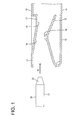
FIG. 1 is a section showing a state before a tab is inserted into a main portion in a terminal fitting according to a first embodiment of the invention, -
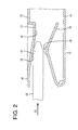
FIG. 2 is a section showing a state during insertion of the tab into the main portion, -
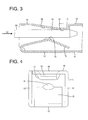
FIG. 3 is a section showing a state where the tab is inserted in the main portion, -
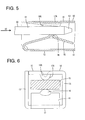
FIG. 4 is a front view of a female terminal, -
FIG. 5 is a section showing a state before a tab is inserted into a main portion in a terminal fitting according to a second embodiment, -
FIG. 6 is a front view showing a state where the tab is inserted in the main portion, -
FIG. 7 is a front view of a female terminal in a terminal fitting according to a third embodiment, -
FIG. 8 is a section showing a state before a tab is inserted into a main portion in a terminal fitting according to a fourth embodiment, -
FIG. 9 is a section showing a state during insertion of a tab into a main portion in a terminal fitting according to a fifth embodiment, -
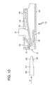
FIG. 10 is a section showing a state before a tab is inserted into a main portion in a terminal fitting according to a sixth embodiment, and -
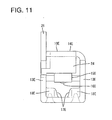
FIG. 11 is a front view of a female terminal. - A first preferred embodiment of the present invention is described with reference to
FIGS. 1 to 4 . A terminal fitting according to the first embodiment is composed of at least one pair of female andmale terminals terminals - The
male terminal 50 includes atab 51. Thetab 51 has a substantially flat shape extending in forward and backward directions (longitudinal direction). The outer circumferential surface of a leading end side of thetab 51 particularly is cut or hammered to form a tapered guidingsurface 52. - The
female terminal 10 includes a tubularmain portion 11. A wire connection portion (particularly comprising an unillustrated crimping portion) is formed behind themain portion 11. The wire connection portion is connectable to an unillustrated wire particularly in that the crimping portion is crimped and connected to an end portion of an unillustrated wire. - The
main portion 11 particularly is in the form of a substantially rectangular tube and includes abase plate 12 continuous with the wire connection portion (particularly the crimping portion), a pair ofside plates 13 standing up from the opposite widthwise ends of thebase plate 12 and aceiling plate 14 bridging the upper ends of one and theother side plates 13. Aresilient contact piece 15 is formed in or at themain portion 11. Theresilient contact piece 15 particularly is formed to have a substantially mountain shape by folding a part projecting forward from the front end of thebase plate 12 backward. A top portion of theresilient contact piece 15 particularly is hammered to form a rounded or substantiallysemispherical contact portion 16 projecting upward or inward. Such aresilient contact piece 15 is resiliently deformable in a direction intersecting a tab insertion direction ID (particularly substantially upward and downward) with its part continuous with the front end of thebase plate 12 as a supporting point. - The
ceiling plate 14 is formed with a receivingportion 17 at a position substantially facing theresilient contact piece 15 in a resiliently deforming direction of theresilient contact piece 15. The receivingportion 17 particularly is formed by hammering a widthwise intermediate or central part of theceiling plate 14 to project inwardly and/or substantially in the form of a rib extending in forward and backward directions, and/or has a trapezoidal cross section. An inner surface of the receivingportion 17 particularly substantially is even and wide in its entirety. Further, the inner surface of the receivingportion 17 is formed with a guidingportion 18 inclined to gradually approach theresilient contact piece 15 from its front end toward its back side. A starting point of the inclination of the guidingportion 18 particularly is located between the front end of theresilient contact piece 15 and thecontact portion 16, and an end point of the inclination of the guidingportion 18 is located between thecontact portion 16 and the rear end of theresilient contact piece 15. In other words, thecontact portion 16 is arranged to substantially face an intermediate position of the guidingportion 18. Thus, the guidingportion 18 is formed with such a length range from a position before a contact position of thetab 51 with thecontact portion 16 to the contact position. - A vertical distance between the end point of the inclination of the guiding
portion 18 and the top of thecontact portion 16 when theresilient contact piece 15 is in its natural state is set to be smaller than the thickness of thetab 51. Further, the inner surface of the receivingportion 17 particularly is formed with a substantially horizontal and/or wideflat surface 19 from the end point of the inclination of the guidingportion 18 to the rear end of the receivingportion 17. - The terminal fitting according to this embodiment is structured as above. Next, how to connect the terminal fitting is described.
- First of all, the
male terminal 50 is at least partly accommodated in an unillustrated male connector housing and thefemale terminal 10 is also at least partly accommodated in an unillustrated female connector housing. Subsequently, the two connector housings are connected with each other. Then, thetab 51 is at least partly inserted into themain portion 11 in the tab insertion direction ID e.g. from front. As shown inFIG. 2 , in an insertion process, thetab 51 comes into contact with the guidingportion 18 before coming into contact with thecontact portion 16 and is or may be displaced in a direction intersecting with the tab insertion direction ID or little by little toward thecontact portion 16 while substantially sliding on the guidingportion 18. Subsequently, thetab 51 comes into contact with thecontact portion 16 from above to resiliently deform theresilient contact piece 15 substantially outward or downward. Also during resilient deformation of theresilient contact piece 15, thetab 51 keeps substantially sliding on the guidingportion 18. When a leading end portion of thetab 51 reaches a position to be held in contact with theflat surface 19 as shown inFIG. 3 in this way, thetab 51 is resiliently tightly held between the receivingportion 17 and theresilient contact piece 15, with the result that both female andmale terminals - As described above, according to this embodiment, the
tab 51 is guided by the guidingportion 18 and reaches the position to be held in contact with thecontact portion 16 when being at least partly inserted into themain portion 11. Thus, as compared with the case where thetab 51 suddenly comes into contact with thecontact portion 16, a sudden increase in insertion resistance can be prevented. In this case, since thecontact portion 16 is arranged to substantially face the intermediate position of the guidingportion 18, a guiding function by the guidingportion 18 can be displayed with thetab 51 held in contact with thecontact portion 16. Therefore, insertion resistance accompanying the contact of thetab 51 and thecontact portion 16 can be gradually increased, wherefore operability upon bringing both female andmale terminals - Since the guiding
portion 18 particularly is formed on the inner surface of the receivingportion 17 of themain portion 11, the receivingportion 17 can have both a function of holding thetab 51 between theresilient contact piece 15 and itself and a function of guiding thetab 51. As a result, the construction of themain portion 11 can be simplified. - Accordingly, to improve operability at the time of terminal connection, a
tab 51 of amale terminal 50 is to be at least partly inserted into amain portion 11 of afemale terminal 10. Thetab 51 comes substantially into contact with acontact portion 16 of aresilient contact piece 15, whereby both female andmale terminals portion 18 for guiding thetab 51 at least partly inserted into thismain portion 11 to a position where thetab 51 comes into contact with thecontact portion 16 is formed on an inner surface of themain portion 11. The guidingportion 18 is formed from a position before a contact position of thetab 51 with thecontact portion 16 to the contact position while being inclined with respect to an inserting direction ID of thetab 51. -
FIGS. 5 and 6 show a second preferred embodiment of the present invention. In thisfemale terminal 10, a widthwise intermediate or central part of aceiling plate 14 of amain portion 11 is hammered or deformed to substantially project inward or downward, thereby forming anarrow receiving portion 17A. This receivingportion 17A particularly has a substantially V- or U-shaped cross section. A top portion of the receivingportion 17A serves as a guidingportion 18A inclined to gradually approach aresilient contact piece 15 from its front end toward its rear end. The other construction is substantially similar to or same as that of the first embodiment. - In the process of inserting a
tab 51 into themain portion 11, thetab 51 is guided toward or to a contact position with acontact portion 16 by the guidingportion 18A. When being inserted to a proper depth in themain portion 11, thetab 51 is tightly held between the guidingportion 18A and thecontact portion 16 while being supported at two points. In this way, bothterminals -
FIG. 7 shows a third embodiment of the present invention. In thisfemale terminal 10, opposite widthwise sides of aceiling plate 14 of amain portion 11 are hammered or deformed to substantially project inward or downward, thereby forming a pair of substantially narrow receivingportions 17B. In other words, the pair of receivingportions 17B overall have a substantially W-shape. Each receivingportion 17B has a substantially U-shaped cross section. A top or distal portion of each receivingportion 17B serves as a guidingportion 18B inclined to gradually approach aresilient contact piece 15 from its front end toward its rear end. The other construction is substantially similar to or same as that of the first embodiment. - [0029] In the process of inserting a
tab 51 into themain portion 11, thetab 51 is guided to a contact position with acontact portion 16 by the respective guidingportions 18B. When being inserted to a proper depth in themain portion 11, thetab 51 is tightly held between the respective guidingportions 18B and thecontact portion 16 while being supported at three points. In this way, bothterminals -
FIG. 8 shows a fourth embodiment of the present invention. A receivingportion 17C formed at aceiling plate 14 of thisfemale terminal 10 is formed with no guiding portion. Specifically, not a guiding portion, but a substantially flat surface 19C is formed at a position of the receivingportion 17C substantially facing acontact portion 16. Aninclined portion 21 shorter than the guidingportion 18 in forward and backward directions is formed at a front end portion of the receivingportion 17C. The other construction of thefemale terminal 10 is substantially similar to or same as that of the first embodiment. - On the other hand, an
inclined projection 53 is formed on the outer circumferential surface of a leading end side of atab 51. The upper surface of theinclined projection 53 serves as a guidingportion 54 gradually inclined upward or outward from an end point of a guidingsurface 52 toward a back side. The guidingportion 54 particularly substantially is even and/or wide. Such a guidingportion 54 is also formed from a position before a contact position of thetab 51 with acontact portion 16 to the contact position with thecontact portion 16. - In the process of inserting the
tab 51 into amain portion 11, the guidingportion 54 slides on theinclined portion 21 of the receivingportion 17C and thetab 51 is displaced toward aresilient contact piece 15. While the guidingportion 18 substantially is sliding on theinclined portion 21 of the receivingportion 17C, thetab 51 comes into contact with thecontact portion 16 from above to resiliently deform theresilient contact piece 15 in a direction intersecting with the tab inserting direction ID or substantially downward. When being inserted to a proper depth in themain portion 11, thetab 51 is resiliently tightly held between the flat surface 19C of the receivingportion 17C and thecontact portion 16, whereby bothterminals - According to the fourth embodiment, the guiding portion can be deleted from the
female terminal 10 and the construction of thefemale terminal 10 can be simplified since the guidingportion 54 is formed on the outer circumferential surface of thetab 51. -
FIG. 9 shows a fifth preferred embodiment of the present invention. In thisfemale terminal 10, a part of aceiling plate 14 is cut and bent into amain portion 11, thereby forming a receivingportion 17D. An inner surface of the receivingportion 17D is formed with a guidingportion 18D gradually inclined toward aresilient contact piece 15 from its front end toward its rear side and a substantially horizontalflat surface 19D from an end point of the inclination of the guidingportion 18D to the rear end of the receivingportion 17D. Further, a part of theceiling plate 14 before the receivingportion 17 is hammered or deformed to substantially project inward or downward, thereby forming a front receivingportion 22. A substantially horizontal and/or wide supportingsurface 23 particularly is formed on an inner surface of the front receivingportion 22. The other construction is substantially similar to or same as that of the first embodiment. - In the process of inserting the
tab 51 into themain portion 11, the upper surface of thetab 51 slides on the supportingsurface 23 of the front receivingportion 22 and the leading end of thetab 51 slides on the guidingportion 18D, whereby thetab 51 is substantially displaced toward thecontact portion 16. While the leading end of thetab 51 substantially is sliding on the guidingportion 18D, theresilient contact piece 15 is resiliently pushed down by thetab 51 to increase insertion resistance gradually or little by little. When being inserted to a proper depth in themain portion 11, thetab 51 is resiliently tightly held between theflat surface 19D of the receivingportion 17D and thecontact portion 16, whereby bothterminals - According to the fifth embodiment, since the guiding
portion 18D is formed on the inner surface of the receivingportion 17D particularly formed by cutting the part of theceiling plate 14 of themain portion 11 and bending this cut part toward thecontact portion 16, a degree of freedom in the form of the guidingportion 18D can be increased as compared with the case where the guiding portion is formed by hammering theceiling plate 14 to project toward thecontact portion 16. -
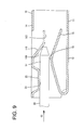
FIGS. 10 and11 show a sixth preferred embodiment of the present invention. This differs from the terminal fitting of the first embodiment in its basic structure. Amain portion 11 E of afemale terminal 10E has an upper portion (preferably substantially an upper half) thereof closed by a closingwall 24 hanging down or inwardly or projecting from the front end of aceiling plate 14E, and aninsertion opening 25 for atab 51 E is formed in a lower portion (preferably substantially in a lower half). At least onestabilizer 25 is formed to stand up from the upper end of aside plate 13E particularly by cutting and bending a part of theceiling plate 14E. A resiliently deformableresilient contact piece 15E is formed in or at or on themain portion 11E. Theresilient contact piece 15E particularly is formed by folding a part extending backward from the rear end of theceiling plate 14E forward and closely bending the forward extending part at a position facing theinsertion opening 25 such that the leading end thereof extends up to the inner surface of theceiling plate 14E. Acontact portion 16E is formed to project at a bottom end of a closely bent part of theresilient contact piece 15E. - Substantially opposite widthwise end portions of a
bottom plate 12E are hammered or deformed to project inward or upward, thereby forming a pair of receivingportions 17E. First guidingportions 18E inclined to gradually approach theresilient contact piece 15E from the front end of thebottom plate 12E toward a rear side thereof are formed on inner surfaces of therespective receiving portions 17E. Therespective receiving portions 17E are arranged at the substantially opposite sides of thecontact portion 16E with respect to a width direction as shown inFIG. 11 . - On the other hand, the outer circumferential surface of the
tab 51 E are cut at substantially opposite widthwise sides thereof, thereby forming a pair ofsecond guiding portions 54E gradually sloped downward from the leading ends thereof toward rear sides thereof. The respectivesecond guiding portions 54E are in such a positional relationship as to at least partly overlap a guidingsurface 52E formed on the outer circumferential surface of a leading end side of thetab 51 E. - In the process of at least partly inserting the
tab 51 E into themain portion 11E, the respectivesecond guiding portions 54E slide on the corresponding first guidingportions 18E to gradually displace thetab 51 E substantially toward thecontact portion 16E. When thetab 51 E comes into contact with thecontact portion 16E laterally or from below, theresilient contact piece 15E is resiliently deformed outward or upward. Also during this time, a sliding contact state of the first andsecond guiding portions tab 51 E gradually or little by little. When being inserted to a proper depth in themain portion 11E, thetab 51 E is tightly held between the receivingportions 17E and thecontact portion 16E, whereby bothterminals - According to the sixth embodiment, a contact load accompanying the contact of the
tab 51 E and thecontact portion 16E can be increased by a smaller degree, wherefore operability is further improved. - The present invention is not limited to the above described and illustrated embodiments. For example, the following embodiments are also included in the technical scope of the present invention.
- (1) The guiding portion(s) formed on the inner surface of the main portion may be arranged at position(s) different from the receiving portion(s).
- (2) It is sufficient for the guiding portion(s) formed on the inner surface of the main portion to extend from the position before the contact position of the tab with the contact portion to the contact position. The guiding portion(s) may be formed at the same position as the contact portion or at a position not overlapping the contact portion with respect to forward and backward directions.
-
- 10, 10E
- female terminal
- 11, 11 E
- main portion
- 14, 14E
- ceiling plate (one wall)
- 15, 15E
- resilient contact piece
- 16, 16E
- contact portion
- 17, 17A, 17B, 17C, 17D, 17E
- receiving portion
- 18, 18A, 18B, 18D, 54
- guiding portion
- 18E
- first guiding portion (guiding portion)
- 50, 50E
- male terminal
- 51, 51E
- tab
- 54E
- second guiding portion (guiding portion)
Claims (15)
- A terminal fitting, comprising:a female terminal (10; 10E) including a substantially tubular main portion (11;
11E), anda male terminal (50; 50E) including a tab (51; 51 E) to be at least partly inserted into the main portion (11; 11E),a resiliently deformable resilient contact piece (15; 15E) being formed in or at the main portion (11; 11E), and both male and female terminals (10, 50; 10E, 50E) being electrically connected by the contact of the tab (51; 51 E) at least partly inserted into the main portion (11; 11E) with a contact portion (16; 16E) of the resilient contact piece (15; 15E),
wherein:at least either one of an inner surface of the main portion (11; 11E) and an outer surface of the tab (51; 51 E) is formed with at least one guiding portion (18; 18A; 18B; 18D; 54; 54E) for guiding the tab (51; 51 E) inserted into the main portion (11; 11E) to a position where the tab (51; 51 E) comes into contact with the contact portion (16; 16E), andthe guiding portion (18; 18A; 18B; 18D; 54; 54E) is inclined with respect to an inserting direction (ID) of the tab (51; 51 E) and formed from a position before a contact position of the tab (51; 51 E) with the contact portion (16; 16E) at least to the contact position. - A terminal fitting according to claim 1, wherein:a receiving portion (17; 17A; 17B; 17C; 17D; 17E) for tightly holding the tab (51; 51 E) at least partly inserted into the main portion (11; 11E) between the contact portion (16; 16E) and itself is formed to project from the inner surface of the main portion (11; 11E).
- A terminal fitting according to claim 2, wherein the guiding portion (18; 18A; 18B; 18D) is formed on an inner surface of the receiving portion (17; 17A; 17B; 17C; 17D; 17E).
- A terminal fitting according to claim 2 or 3, wherein the guiding portion (18D) is formed by cutting a part of one wall of the main portion (11) and substantially bending the cut part toward the contact portion (16).
- A terminal fitting according to any one of the preceding claims, wherein the guiding portion (54; 54E) is formed on the outer surface of the tab (51; 51 E).
- A terminal fitting according to any one of the preceding claims, wherein:a receiving portion (17; 17A; 17B; 17C; 17D; 17E) for tightly holding the tab (51; 51 E) at least partly inserted into the main portion (11; 11E) between the contact portion (16; 16E) and itself is formed to project from the inner surface of the main portion (11; 11E), andthe guiding portion (18; 18A; 18B; 18D; 54; 54E) is so formed that the guiding portion (18; 18A; 18B; 18D; 54; 54E) and both an inner surface of the receiving portion (17; 17A; 17B; 17C; 17D; 17E) and the outer surface of the tab (51; 51 E) are substantially slidable on each other.
- A terminal fitting according to any one of the preceding claims, wherein the contact portion (16; 16E) is arranged to substantially face an intermediate position of the guiding portion (18; 18A; 18B; 18D; 54; 54E).
- A female terminal (10; 10E) including a substantially tubular main portion (11; 11E) into which a male terminal (50; 50E) including a tab (51; 51 E) is to be at least partly inserted, the female terminal (10; 10E) comprising:a resiliently deformable resilient contact piece (15; 15E) being formed in or at the main portion (11; 11E), and the female terminal (10; 10E) being electrically connected to the male terminal (50; 50E) by the contact of the tab (51; 51 E) at least partly inserted into the main portion (11; 11E) with a contact portion (16; 16E) of the resilient contact piece (15; 15E),
wherein:an inner surface of the main portion (11; 11E) is formed with at least one guiding portion (18; 18A; 18B; 18D) for guiding the tab (51; 51 E) inserted into the main portion (11; 11 E) to a position where the tab (51; 51 E) comes into contact with the contact portion (16; 16E), andthe guiding portion (18; 18A; 18B; 18D) is inclined with respect to an inserting direction (ID) of the tab (51; 51 E) and formed from a position before a contact position of the tab (51; 51 E) with the contact portion (16; 16E) at least to the contact position. - A female terminal (10; 10E) according to claim 8, wherein:a receiving portion (17; 17A; 17B; 17C; 17D; 17E) for tightly holding the tab (51; 51 E) at least partly inserted into the main portion (11; 11E) between the contact portion (16; 16E) and itself is formed to project from the inner surface of the main portion (11; 11E).
- A female terminal (10; 10E) according to claim 9, wherein the guiding portion (18; 18A; 18B; 18D) is formed on an inner surface of the receiving portion (17; 17A; 17B; 17C; 17D; 17E).
- A female terminal (10; 10E) according to claim 9 or 10, wherein the guiding portion (18D) is formed by cutting a part of one wall of the main portion (11) and substantially bending the cut part toward the contact portion (16).
- A female terminal (10; 10E) according to any one of the preceding claims 9 to 11, wherein:a receiving portion (17; 17A; 17B; 17C; 17D; 17E) for tightly holding the tab (51; 51 E) at least partly inserted into the main portion (11; 11E) between the contact portion (16; 16E) and itself is formed to project from the inner surface of the main portion (11; 11E), andthe guiding portion (18; 18A; 18B; 18D) is so formed that the guiding portion (18; 18A; 18B; 18D) and both an inner surface of the receiving portion (17; 17A; 17B; 17C; 17D; 17E) and the outer surface of the tab (51; 51 E) are substantially slidable on each other.
- A method of establishing an electric contact of a terminal fitting, comprising the following steps:providing a female terminal (10; 10E) including a substantially tubular main portion (11; 11E), andat least partly inserting a tab (51; 51 E) of a male terminal (50; 50E) into the main portion (11; 11E), thereby electrically connecting both male and female terminals (10, 50; 10E, 50E) by the contact of the tab (51; 51 E) at least partly inserted into the main portion (11; 11E) with a contact portion (16; 16E) of
a resiliently deformable resilient contact piece (15; 15E) being formed in or at the main portion (11; 11E),while guiding the tab (51; 51 E) inserted into the main portion (11; 11E) by means of at least one guiding portion (18; 18A; 18B; 18D; 54; 54E), which is provided on at least either one of an inner surface of the main portion (11; 11E) and an outer surface of the tab (51; 51 E), to a position where the tab (51; 51 E) comes into contact with the contact portion (16; 16E),wherein the guiding portion (18; 18A; 18B; 18D; 54; 54E) is inclined with respect to an inserting direction (ID) of the tab (51; 51 E) and formed from a position before a contact position of the tab (51; 51 E) with the contact portion (16; 16E) at least to the contact position. - A method according to claim 13, further comprising tightly holding the tab (51; 51 E) at least partly inserted into the main portion (11; 11E) between the contact portion (16; 16E) and a receiving portion (17; 17A; 17B; 17C; 17D; 17E), which is formed to project from the inner surface of the main portion (11; 11E).
- A method according to claim 14, wherein the guiding portion (18; 18A; 18B; 18D) is formed on an inner surface of the receiving portion (17; 17A; 17B; 17C; 17D; 17E).
Priority Applications (1)
| Application Number | Priority Date | Filing Date | Title |
|---|---|---|---|
| EP11009725.0A EP2432079B1 (en) | 2009-12-02 | 2010-11-10 | Terminal fitting, female terminal fitting and method of establishing an electric contact of a terminal fitting |
Applications Claiming Priority (1)
| Application Number | Priority Date | Filing Date | Title |
|---|---|---|---|
| JP2009274696A JP5375564B2 (en) | 2009-12-02 | 2009-12-02 | Terminal fitting |
Related Child Applications (1)
| Application Number | Title | Priority Date | Filing Date |
|---|---|---|---|
| EP11009725.0A Division EP2432079B1 (en) | 2009-12-02 | 2010-11-10 | Terminal fitting, female terminal fitting and method of establishing an electric contact of a terminal fitting |
Publications (1)
| Publication Number | Publication Date |
|---|---|
| EP2330691A1 true EP2330691A1 (en) | 2011-06-08 |
Family
ID=43478117
Family Applications (2)
| Application Number | Title | Priority Date | Filing Date |
|---|---|---|---|
| EP11009725.0A Not-in-force EP2432079B1 (en) | 2009-12-02 | 2010-11-10 | Terminal fitting, female terminal fitting and method of establishing an electric contact of a terminal fitting |
| EP10014470A Withdrawn EP2330691A1 (en) | 2009-12-02 | 2010-11-10 | Terminal fitting, female terminal fitting and method of establishing an electric contact of a terminal fitting |
Family Applications Before (1)
| Application Number | Title | Priority Date | Filing Date |
|---|---|---|---|
| EP11009725.0A Not-in-force EP2432079B1 (en) | 2009-12-02 | 2010-11-10 | Terminal fitting, female terminal fitting and method of establishing an electric contact of a terminal fitting |
Country Status (4)
| Country | Link |
|---|---|
| US (2) | US8152576B2 (en) |
| EP (2) | EP2432079B1 (en) |
| JP (1) | JP5375564B2 (en) |
| CN (1) | CN102148449B (en) |
Families Citing this family (20)
| Publication number | Priority date | Publication date | Assignee | Title |
|---|---|---|---|---|
| CN102790308B (en) * | 2011-05-20 | 2015-08-12 | 泰科电子(上海)有限公司 | Electric connector terminal |
| CN102354831B (en) * | 2011-08-15 | 2013-10-16 | 浙江正泰建筑电器有限公司 | Terminal apparatus without screw thread |
| JP2013098088A (en) * | 2011-11-02 | 2013-05-20 | Sumitomo Wiring Syst Ltd | Female type terminal fitting |
| JP5829937B2 (en) | 2012-02-15 | 2015-12-09 | 矢崎総業株式会社 | Terminal connection structure |
| JP5247902B1 (en) * | 2012-02-24 | 2013-07-24 | 日本航空電子工業株式会社 | Electrical connector |
| JP2014049375A (en) * | 2012-09-03 | 2014-03-17 | Yazaki Corp | Connection terminal |
| CN202772303U (en) * | 2012-09-04 | 2013-03-06 | 泰科电子(上海)有限公司 | Electrical connector and electrical connector assembly |
| US9118130B1 (en) * | 2014-02-06 | 2015-08-25 | Delphi Technologies, Inc. | Low insertion force terminal |
| WO2015125682A1 (en) * | 2014-02-18 | 2015-08-27 | 矢崎総業株式会社 | Connection terminal |
| JP5831611B1 (en) * | 2014-09-19 | 2015-12-09 | 第一精工株式会社 | Connector terminal connection structure |
| US20160344127A1 (en) * | 2015-05-20 | 2016-11-24 | Delphi Technologies, Inc. | Electroconductive material with an undulating surface, an electrical terminal formed of said material, and a method of producing said material |
| JP6154430B2 (en) * | 2015-06-02 | 2017-06-28 | 矢崎総業株式会社 | Female terminal fitting and connector having the same |
| US10090608B2 (en) | 2016-09-29 | 2018-10-02 | Delphi Technologies, Inc. | Electrical connection system having a terminal with contact ridges |
| JP6807024B2 (en) * | 2017-04-14 | 2021-01-06 | 株式会社オートネットワーク技術研究所 | Female terminal |
| JP6588943B2 (en) | 2017-06-20 | 2019-10-09 | 矢崎総業株式会社 | Terminal connection structure |
| JP6576979B2 (en) * | 2017-07-20 | 2019-09-18 | 矢崎総業株式会社 | Terminal connection structure |
| JP2019029216A (en) * | 2017-07-31 | 2019-02-21 | 住友電装株式会社 | Female terminal |
| JP6802227B2 (en) * | 2018-09-14 | 2020-12-16 | 矢崎総業株式会社 | Connecting terminal |
| JP7396203B2 (en) * | 2020-06-01 | 2023-12-12 | 株式会社オートネットワーク技術研究所 | Connectors with built-in fuses and connector structures |
| JP7168626B2 (en) * | 2020-10-23 | 2022-11-09 | 矢崎総業株式会社 | Connecting terminal |
Citations (7)
| Publication number | Priority date | Publication date | Assignee | Title |
|---|---|---|---|---|
| EP0652605A1 (en) * | 1993-11-04 | 1995-05-10 | Sumitomo Wiring Systems, Ltd. | Female terminal fitting for connector |
| US5443592A (en) * | 1993-10-26 | 1995-08-22 | Connecteurs Cinch | Female electrical contact member |
| US5707259A (en) * | 1995-07-24 | 1998-01-13 | Yazaki Corporation | Female terminal |
| JP2003346958A (en) | 2002-05-29 | 2003-12-05 | Sumitomo Wiring Syst Ltd | Female terminal fitting |
| US20070021013A1 (en) * | 2005-07-21 | 2007-01-25 | Tyco Electronics Corporation | Dual beam receptacle contact |
| DE102006009074A1 (en) * | 2006-02-28 | 2007-08-30 | Robert Bosch Gmbh | Electrical plug-in connector for use in automotive area, has holding arm extending into initial condition of connector with free end in plug receiver, and contact segment and/or upper side wall for contacting contact pin |
| EP1919036A2 (en) * | 2006-11-01 | 2008-05-07 | Sumitomo Wiring Systems, Ltd. | A terminal fitting and a connecting method |
Family Cites Families (18)
| Publication number | Priority date | Publication date | Assignee | Title |
|---|---|---|---|---|
| JP2772325B2 (en) * | 1992-03-02 | 1998-07-02 | 矢崎総業株式会社 | Relay terminal for male terminal connection |
| JPH0587837U (en) * | 1992-04-23 | 1993-11-26 | 矢崎総業株式会社 | Male terminal structure of connector |
| JPH0734563U (en) * | 1993-12-08 | 1995-06-23 | 住友電装株式会社 | Male terminal fitting |
| JP2734994B2 (en) * | 1994-07-20 | 1998-04-02 | 住友電装株式会社 | Male terminal fitting |
| JP3082613B2 (en) * | 1995-02-22 | 2000-08-28 | 住友電装株式会社 | Female terminal fitting |
| JP3807646B2 (en) * | 1997-10-31 | 2006-08-09 | 矢崎総業株式会社 | Terminal sag prevention structure |
| JPH11214058A (en) * | 1998-01-29 | 1999-08-06 | Yazaki Corp | Female terminal |
| JP3686551B2 (en) * | 1999-06-17 | 2005-08-24 | 矢崎総業株式会社 | Terminal bracket |
| JP3645449B2 (en) * | 1999-06-17 | 2005-05-11 | 矢崎総業株式会社 | Terminal structure |
| JP2002015803A (en) * | 2000-06-30 | 2002-01-18 | Sumitomo Wiring Syst Ltd | Connection structure of terminal fittings |
| JP3729327B2 (en) * | 2000-08-28 | 2005-12-21 | 住友電装株式会社 | Female terminal bracket |
| JP4379231B2 (en) * | 2004-07-07 | 2009-12-09 | 住友電装株式会社 | Female terminal bracket |
| JP4483601B2 (en) * | 2005-01-28 | 2010-06-16 | 住友電装株式会社 | Female terminal bracket |
| JP2006216321A (en) * | 2005-02-02 | 2006-08-17 | Sumitomo Wiring Syst Ltd | Terminal fitting |
| JP2007149504A (en) * | 2005-11-28 | 2007-06-14 | Yazaki Corp | Female terminals and connectors |
| JP4858293B2 (en) * | 2007-05-08 | 2012-01-18 | 住友電装株式会社 | Female terminal bracket |
| JP2008293722A (en) * | 2007-05-23 | 2008-12-04 | Sumitomo Wiring Syst Ltd | connector |
| JP5179926B2 (en) * | 2008-04-07 | 2013-04-10 | 日本圧着端子製造株式会社 | Male terminal and connector having the same |
-
2009
- 2009-12-02 JP JP2009274696A patent/JP5375564B2/en not_active Expired - Fee Related
-
2010
- 2010-11-10 EP EP11009725.0A patent/EP2432079B1/en not_active Not-in-force
- 2010-11-10 EP EP10014470A patent/EP2330691A1/en not_active Withdrawn
- 2010-11-24 US US12/954,178 patent/US8152576B2/en not_active Expired - Fee Related
- 2010-11-25 CN CN2010105634289A patent/CN102148449B/en not_active Expired - Fee Related
-
2012
- 2012-01-11 US US13/347,939 patent/US8206187B2/en not_active Expired - Fee Related
Patent Citations (7)
| Publication number | Priority date | Publication date | Assignee | Title |
|---|---|---|---|---|
| US5443592A (en) * | 1993-10-26 | 1995-08-22 | Connecteurs Cinch | Female electrical contact member |
| EP0652605A1 (en) * | 1993-11-04 | 1995-05-10 | Sumitomo Wiring Systems, Ltd. | Female terminal fitting for connector |
| US5707259A (en) * | 1995-07-24 | 1998-01-13 | Yazaki Corporation | Female terminal |
| JP2003346958A (en) | 2002-05-29 | 2003-12-05 | Sumitomo Wiring Syst Ltd | Female terminal fitting |
| US20070021013A1 (en) * | 2005-07-21 | 2007-01-25 | Tyco Electronics Corporation | Dual beam receptacle contact |
| DE102006009074A1 (en) * | 2006-02-28 | 2007-08-30 | Robert Bosch Gmbh | Electrical plug-in connector for use in automotive area, has holding arm extending into initial condition of connector with free end in plug receiver, and contact segment and/or upper side wall for contacting contact pin |
| EP1919036A2 (en) * | 2006-11-01 | 2008-05-07 | Sumitomo Wiring Systems, Ltd. | A terminal fitting and a connecting method |
Also Published As
| Publication number | Publication date |
|---|---|
| JP5375564B2 (en) | 2013-12-25 |
| CN102148449A (en) | 2011-08-10 |
| US20120108114A1 (en) | 2012-05-03 |
| US8152576B2 (en) | 2012-04-10 |
| CN102148449B (en) | 2013-09-18 |
| EP2432079B1 (en) | 2014-12-24 |
| US20110130051A1 (en) | 2011-06-02 |
| US8206187B2 (en) | 2012-06-26 |
| EP2432079A1 (en) | 2012-03-21 |
| JP2011119109A (en) | 2011-06-16 |
Similar Documents
| Publication | Publication Date | Title |
|---|---|---|
| EP2432079A1 (en) | Terminal fitting, female terminal fitting and method of establishing an electric contact of a terminal fitting | |
| EP1990866A1 (en) | A female terminal fitting | |
| EP2852004B1 (en) | Terminal fitting | |
| CN100566038C (en) | Female terminal fitting is used for the blank of several terminals joint and the method that forms female terminal fitting | |
| CN101494333B (en) | Terminals, a terminal connecting structure and a connecting method | |
| EP2166624A1 (en) | A resilient plug, a waterproof connector and a method of assembling it | |
| US20050032440A1 (en) | Female terminal fitting and method of assembling such terminal fitting | |
| EP2309603A1 (en) | Female terminal fitting and method of connecting it | |
| EP2239814A1 (en) | Terminal fitting, connector and assembling method | |
| EP2157669A1 (en) | A connector and assembling method therefor | |
| US8523619B2 (en) | Terminal fitting | |
| EP2485334A1 (en) | Multi-contact terminal fitting | |
| US8454394B2 (en) | Terminal fitting having an auxilary resilient piece | |
| JP2014110214A (en) | Female terminal | |
| EP1811608B1 (en) | A terminal fitting and connector provided therewith | |
| EP2544309B1 (en) | Terminal fitting and method of producing it | |
| US10985486B2 (en) | Female terminal | |
| JP6143194B2 (en) | Male terminal bracket | |
| EP2164132A1 (en) | A terminal fitting, a connector, and assembling method therefor | |
| CN103022779B (en) | Connector | |
| EP2187478A1 (en) | A terminal fitting, a wire connection structure and a connecting method | |
| JP3122589U (en) | Terminal fitting | |
| JP2008192419A (en) | Terminal fitting and connector | |
| JP2002042949A (en) | Terminal fitting | |
| JP2015207372A (en) | Female type terminal fitting |
Legal Events
| Date | Code | Title | Description |
|---|---|---|---|
| PUAI | Public reference made under article 153(3) epc to a published international application that has entered the european phase |
Free format text: ORIGINAL CODE: 0009012 |
|
| AK | Designated contracting states |
Kind code of ref document: A1 Designated state(s): AL AT BE BG CH CY CZ DE DK EE ES FI FR GB GR HR HU IE IS IT LI LT LU LV MC MK MT NL NO PL PT RO RS SE SI SK SM TR |
|
| AX | Request for extension of the european patent |
Extension state: BA ME |
|
| 17P | Request for examination filed |
Effective date: 20111124 |
|
| 17Q | First examination report despatched |
Effective date: 20120222 |
|
| GRAP | Despatch of communication of intention to grant a patent |
Free format text: ORIGINAL CODE: EPIDOSNIGR1 |
|
| RIC1 | Information provided on ipc code assigned before grant |
Ipc: H01R 13/629 20060101ALI20150226BHEP Ipc: H01R 13/11 20060101ALI20150226BHEP Ipc: H01R 13/05 20060101AFI20150226BHEP |
|
| INTG | Intention to grant announced |
Effective date: 20150312 |
|
| INTG | Intention to grant announced |
Effective date: 20150319 |
|
| STAA | Information on the status of an ep patent application or granted ep patent |
Free format text: STATUS: THE APPLICATION IS DEEMED TO BE WITHDRAWN |
|
| 18D | Application deemed to be withdrawn |
Effective date: 20150730 |