EP2330560B1 - Method and device for processing vector graphics - Google Patents
Method and device for processing vector graphics Download PDFInfo
- Publication number
- EP2330560B1 EP2330560B1 EP10785721A EP10785721A EP2330560B1 EP 2330560 B1 EP2330560 B1 EP 2330560B1 EP 10785721 A EP10785721 A EP 10785721A EP 10785721 A EP10785721 A EP 10785721A EP 2330560 B1 EP2330560 B1 EP 2330560B1
- Authority
- EP
- European Patent Office
- Prior art keywords
- polygon
- new drawing
- drawing window
- polygons
- coordinate system
- Prior art date
- Legal status (The legal status is an assumption and is not a legal conclusion. Google has not performed a legal analysis and makes no representation as to the accuracy of the status listed.)
- Active
Links
Images


Classifications
-
- G—PHYSICS
- G06—COMPUTING OR CALCULATING; COUNTING
- G06T—IMAGE DATA PROCESSING OR GENERATION, IN GENERAL
- G06T11/00—Two-dimensional [2D] image generation
- G06T11/20—Drawing from basic elements
- G06T11/23—Drawing from basic elements using straight lines or curves
-
- G—PHYSICS
- G06—COMPUTING OR CALCULATING; COUNTING
- G06T—IMAGE DATA PROCESSING OR GENERATION, IN GENERAL
- G06T11/00—Two-dimensional [2D] image generation
- G06T11/40—Filling planar surfaces by adding surface attributes, e.g. adding colours or textures
Definitions
- the present invention relates to the field of processing multimedia data and particularly to a method and device for reducing a CPU resource consumed by filling a vector graph.
- a vector graph is a geometrical graph described by a series of coordinate points and having a specific shape and attribute.
- FLASH which is an animation format of a vector graph, defines the graph primarily as a line and area. Particularly, the line depicts a contour of a shape of the graph, and the area refers to an enclosed scope defined within the contour of the shape.
- Drawing of a FLASH vector graph primarily involves filling of the area.
- an area is defined by various interlaced colors, and lines defining the contour of the area include straight lines and curves. For a uniform filling algorithm, the area has to be segmented into a series of monochromatic polygons prior to being filled and is filled by filling the polygons.
- the process includes coordinate transformation of vertexes of the polygon, tailoring of the polygon with respect to a drawing window, conversion of the polygon into scan lines in the drawing window and coloring of the scan lines.
- a specific flow of filling a polygon in the prior art is as follows.
- Operation 101 a vector graph is parsed into a series of polygons.
- Operation 102 vertex coordinates of each polygon are transformed through a matrix operation, to map the polygon into a drawing window, where vertex coordinates of the polygon are in 1/20 pixel.
- Operation 103 the polygon is tailored with respect to the drawing window into a polygon in the drawing window.
- Operation 104 a scan conversion algorithm is applied to convert the polygon in the drawing window into a set of scan lines in the drawing window.
- Operation 105 pixels covered by each scan line are colored, where coordinates of intersections of the scan lines are divided by 20 into coordinate values in pixel in the drawing window during coloring.
- vertex coordinates of a polygon are given in 1/20 pixel
- the division operation performed by a CPU is very time-consuming and consumes a considerable CPU resource, thus requiring a great processing capacity of the CPU.
- US 2010/0111437 A1 proposes a method and a system for generating a boundary in the process of rasterizing a vector graphic as well as a method for producing the system and a method for clipping the vector graphic.
- the method for generating a boundary includes: segment-polylining the vector graphic and obtaining data of the line segments; obtaining data of the end pixels according to the data of the line segments; obtaining data of boundary pixels according to the data of the end pixels and the relationship between the data of the end pixels; obtaining bitmap data of the boundary pixels according to the data of the boundary pixels.
- the algorithm used in the invention is very simple and efficient; at the same time, the generation of the bitmap data of the boundary pixels can be carried out synchronously with the generation of bitmap data of the graphic itself.
- the invention can be used to be combined with a variety of scan line filling algorithms and the bitmap information of the boundary pixels can be obtained synchronously and efficiently in the process of rasterizing a vector graphic so that the quality of the output bitmap can be improved and controlled accurately.
- SWF file Format delivers vector graphics, text, video, and sound over the Internet and is supported by Adobe ® Flash ® Player software.
- the SWF file format is designed to be an efficient delivery format, and comprises basic data types including coordinates and 'twips'.
- a 'twip' is a 1/20th of a logical pixel.
- REN HUANG Et Al. "Implementation of an Open VG Rasterizer with Configurable Anti-Aliasing and Multi-Window Scissoring", 2006-09-01, pages 1-6 , describes an Open VG-compliant hardware rasterizer with configurable anti-aliasing and multi-window scissoring.
- This rasterizer requires 129K logic gates with 2KB on-chip SRAM and provides satisfactory image quality with a reasonable rasterizer speed at the operational frequency of 100MHz.
- This document proposes an optimized scanline algorithm, which provides better performance than the conventional scanline algorithm with super-sampline while maintaining the flexibility and the hardware simplicity.
- the document also proposes a fast LUT-based scissoring algorithm, which has zero-latency in most of the cases. The hardware implementation of this rasterizer is explained in detail.
- the invention provides a method and device for processing a vector graph to reduce a CPU resource consumed by filling the vector graph.
- the invention provides a method for rendering a geometric object given in a vector graphic format, wherein the vertex coordinates of the object are given in units of 1/K pixels, i.e. K units corresponding to one true pixel, which includes:
- transforming the vertex coordinates of the polygons into a new drawing coordinate system in which 2 n units correspond to one true pixel, by using a transformation parameter and a transformation matrix, and transforming an original drawing window into the new drawing coordinate system, thereby generating a new drawing window, wherein the transformation parameter is represented by A 2 n /K, and wherein n and K are natural numbers > 1, and n unequal to K;
- the invention further provides a device for rendering a geometric object given in a vector graphic format, wherein the vertex coordinates of the object are given in units of 1/K pixels, i.e. K units corresponding to one true pixel, which includes:
- a parsing unit configured to parse the geometric object into a series of polygons
- a polygon acquiring unit configured to map the relevant part of each of the polygons into the new drawing window
- a scan converting unit configured to convert the parts of the polygons in the new drawing coordinate system in the new drawing window into a set of scan segments
- a shifting unit configured to obtain the true pixel coordinates by shifting the coordinates of the scan segments by n bits to the right;
- a pixel coloring unit configured to color the pixels of the shifted scan segments.
- a division operation is replaced with shifting of coordinate values, and a resulting error of tailoring a polygon is taken into consideration in an operation prior to coloring, thereby the number of division operations is reduced on the precondition of ensuring a correct result, thus the purpose of reducing a consumed CPU resource is finally achieved.
- Fig. 1 illustrates a schematic diagram of a flow chart of a method for filling a vector graph in the prior art
- Fig. 2 illustrates a schematic diagram of a flow chart of a method for filling a vector graph according to an embodiment of the invention
- Fig. 3 illustrates a schematic diagram of an operational process of User Defined Instructions (UDI) according to an embodiment of the invention
- Figs. 4a and 4b illustrate schematic diagrams of a tailor error according to an embodiment of the invention
- Figs. 5a, 5b and 5c illustrate schematic diagrams of a positional relationship between an encircling rectangle and a new drawing window according to an embodiment of the invention
- Figs. 6a, 6b and 6c illustrate schematic diagrams of tailoring a polygon according to an embodiment of the invention
- Fig. 7 illustrates a schematic diagram of an encircling rectangle according to an embodiment of the invention
- Fig. 8 illustrates a schematic diagram of scanning and converting a polygon according to an embodiment of the invention.
- Fig. 9 illustrates a schematic diagram of a structure of a device for processing a vector graph according to an embodiment of the invention.
- the division operations may be replaced with a shift operation, e.g., an operation of dividing by 20 may be replaced with an operation of dividing by a number which is approximate to 20 and is an integer power of 2, so that the division operation can be replaced with a simple integer shift operation.
- a resulting error of tailoring a polygon may be taken into consideration in a calculation process prior to coloring, to thereby eliminate an error in a final result.
- the number which is approximate to 20 and is an integer power of 2 may be 8, 16, 32, 64, etc., and of course may be any other number, and when 20 is replaced with any one of these numbers, a corresponding calculation result prior to coloring of pixels covered by a scan line need to be multiplied by 0.4, 0.8, 1.6, 3.2, etc., to ensure a correct final calculation result.
- a processor of a Reduced Instruction Set Computer for example, is typically provided without any floating point processing unit, and a floating point operation may be performed on such a processor either through a software simulation or a fixed point approximation, the latter of which runs faster than the former in an allowable precision error range. Therefore in an embodiment of the invention, a part of the process involving a floating point operation may be performed through a fixed point approximation by replacing a decimal number with a fixed point number.
- Fig. 2 illustrates a flow of implementing a method for filling a vector graph on a portable multimedia device according to an embodiment of the invention to reduce a consumed CPU resource in the portable multimedia device.
- the method is specified as follows.
- Operation 201 the vector graph is parsed into a series of polygons.
- coordinates of the polygons obtained through parsing are in 1/20 pixel because vertex coordinates of each polygon in a vector graph file are in 1/20 pixel.
- Operation 203 a part of each polygon in the new drawing coordinate system is acquired in a new drawing window.
- Operation 204 the part of the polygon in the new drawing coordinate system in the new drawing window are converted into a set of scan segments.
- Operation 205 true forms of coordinates of the scan segments are shifted by n bits to the right, and pixels on shifted scan segments are colored.
- the operation 202 will be detailed below.
- a coordinate of a vertex of a polygon is defined in a form of a 32-bit integer
- a twiddle factor and a scale factor of the transformation matrix are defined in a form of a 16.16 fixed point number
- a shift factor of the transformation matrix is defined in a form of a 32-bit integer.
- S x is a scale factor in the direction x
- S y is a scale factor in the direction y
- R x is a twiddle factor in the direction x
- R y is a twiddle factor in the direction y
- T x is a shift factor in the direction x
- T y is a shift factor in the direction y.
- x 1 y 1 1 1.6 ⁇ S x 1.6 ⁇ R y 1.6 ⁇ T x 1.6 ⁇ R x 1.6 ⁇ S 1.6 ⁇ T y 0 0 1 ⁇ x 0 y 0 1
- the above Equation indicates that the transformed coordinate value multiplied by 1.6 as required may be obtained through multiplying the scale factors, the twiddle factors and the shift factors of the transformation matrix respectively by 1.6 and then transforming the original coordinate with the matrix multiplied by 1.6.
- the above Equation also indicates that simply the transformation parameter instead of the original coordinate value is multiplied by 1.6 to thereby reduce a calculation effort.
- the transformation process is a process of consecutive multiplications and additions, including two multiplications and three additions.
- a multiplication operation refers to a multiplication of a 32-bit integer with a fixed point number in the format of 16.16 and has a product of a fixed point number in the format of 48.16. Since a final transformation result is a 32-bit integer coordinate value, the product has to be shifted.
- a multiplication operation on two 32-bit integers results in a 64-bit integer, and the 64-bit integer is placed in HI and LO registers by placing the upper 32 bits in the HI register and the lower 32 bits in the LO register.
- Values in the HI and LO registers have to suffer from a shifting operation in order to obtain a 32-bit integer value.
- the upper 16 ones of the bits in the HI register are insignificant bits which may be dispensed with
- the lower 16 ones of the bits in the LO register are a fractional part to be dispensed with
- the lower 16 ones of the bits in the HI register are upper 16 bits of the 32-bit integer coordinate value
- the higher 16 ones of the bits in the LO register are lower 16 bits of the integer coordinate value. Therefore, the 32-bit integer coordinate value may result from the following manipulations on the HI and LO registers:
- the 32-bit integer coordinate value is result from three bit manipulations.
- some complex manipulations may be performed with a single user-defined instruction, and the above manipulations may be performed with a UDI instruction, udi8 rs, rt, rd, (imm ⁇ 3), of the RISC processor.
- the UDI instruction is executed as follows:
- the HI register is taken as the register rs
- the lower 16 ones of the bits in the HI register and the upper 16 ones of the bits in the LO register may be fetched and combined into the 32-bit integer result as required.
- the single-cycle instruction, udi8 rs, rt, rd, (imm ⁇ 3), in UDIs may be executed to perform an operation in a single instruction instead of originally in three instructions, so as to reduce the number of instructions and also the number of cycles to execute the instructions, thereby accelerating the transformation process.
- the upper 16 ones of the bits in the HI register may also be significant bits, which indicate that the transformed coordinate value is so large that they exceed a range which can be represented with a 32-bit integer and an overflow occurs.
- the overflow needs to be handled typically by assigning an overflow transformation result with 0x7FFFFFF (overflow) or 0x80000000 (underflow). Whether the result overflows may be determined from whether the upper 16 ones of the bits in the HI register are significant bits.
- the original drawing window is updated into the new drawing coordinate system.
- Fig. 4a illustrates a position of a polygon relative to a drawing window before the shift factors are multiplied by the transformation parameter
- Fig.4b the position of the polygon relative to the drawing window is changed after the shift factors of the transformation matrix are multiplied by 1.6, thus resulting in an error in tailoring the polygon.
- the drawing window is also updated correspondingly in an embodiment of the invention by transforming coordinates of four vertexes of the drawing window into those expressed in 1/20 pixel and then transforming each of the coordinate by using the following matrix: 1.6 0 0 0 1.6 0 0 0 1
- the polygon is tailored in the updated drawing window to eliminate any tailor error.
- the polygon After vertex coordinates are transformed, the polygon is mapped into the new drawing coordinate system. There are three positional relationships between the polygon and the new drawing window: the polygon is in the new drawing window, the polygon intersects the new drawing window, and the polygon is outside the new drawing window.
- an encircling rectangle refers to a smallest rectangle encircling vertexes of a polygon.
- a positional relationship between a polygon and a drawing window may be determined according to a derived encircling rectangle of the polygon in an embodiment of the invention, and then whether to perform a tailoring process may be determined according to the determined positional relationship, and if no tailoring is needed, then the polygon is acquired directly; otherwise, the polygon is tailored to acquire a part of the polygon in the new drawing window.
- Determining whether to tailor the polygon according to the positional relationship between the encircling rectangle and the new drawing window is implemented as follows: when the encircling rectangle is in the new drawing window, it is determined that no tailoring is needed; and when the encircling rectangle intersects a part of the new drawing window, it is determined that the polygon needs to be tailored.
- Deriving a encircling rectangle of a polygon is a process of acquiring extremums of x and y coordinates of vertexes.
- the encircling rectangle may be derived through a way as follows.
- x i and y i are vertex coordinates of a polygon
- N is the number of vertexes of the polygon
- a positional relationship between the encircling rectangle and the new drawing window may result from a Boolean operation on the encircling rectangle and the rectangle of the new drawing window.
- the positional relationship is as illustrated in Figs. 5a, 5b and 5c , where the encircling rectangle does not intersect the new drawing window in Fig. 5a , the encircling rectangle intersects the new drawing window in Fig. 5b , and the encircling rectangle is in the new drawing window in Fig. 5c .
- the process is terminated; in the case where the encircling rectangle intersects the new drawing window, the polygon needs to be tailored; and in the case where the encircling rectangle is in the new drawing window, scanning and converting may be performed directly while skipping the tailoring process.
- slopes of edges of the polygon are calculated for both tailoring operation and scanning and converting operation.
- the slopes of edges of the polygon may be calculated only once to accommodate the use thereof during tailoring and scanning and converting. Therefore, the slopes of edges of the polygon are firstly calculated prior to tailoring and scanning and converting.
- the calculated slopes are processed into fixed point numbers in the format of 16.16.
- a data structure as shown in Table 1 is filled during calculating the slopes: Table 1 Edge x 1 y 1 x 2 y 2 slope x
- Slope x is processed into a fixed point number in the format of 16.16.
- the edge is a horizontal edge, it is unable to calculate Slope x of the edge, but since the horizontal edge can be eliminated during scanning and converting process because it does not contribute to generation of scan segments during the scanning and converting progress, Slope x of the horizontal edge may be assigned with a fixed value, e.g., 0x7FFFFFFF, which indicates that this Slope x is insignificant and is not used for calculation.
- each value is written into the data structure for use in a subsequent process.
- a polygon may be tailored by acquiring a data structure, Edge, of each edge sequentially in the order of vertexes and then tailoring each edge sequentially with respect to the new drawing window in a tailoring algorithm to thereby resulting in a coordinate of a new vertex.
- Edge a data structure
- the coordinates of endpoints of the edge after tailoring and the Slope x keep unchanged.
- ( x 1 , y 1 ) or ( x 2 , y 2 ) is updated correspondingly with a calculated coordinate of the intersection(s) after tailoring under an update rule as illustrated in Figs.
- the slope, Slope x , of the edge is used in the tailoring algorithm and acquired directly from the data structure, Edge, for use. After the tailoring process is completed, the data structure, Edge, of each edge is updated so that all the edges of the polygon are in the new drawing window.
- a scanning and converting process is thereafter performed to convert the polygon into a set of scan segments on each scan line.
- the scan line refers to a horizontal line in the drawing window traversing the window, and the total number of scan lines in a drawing window is H, i.e., the height of the drawing window in pixel.
- the scan segment refers to a part of the scan line in the polygon, and scan segments on a number, H, of scan lines completely cover the polygon.
- the polygon is colored by coloring these scan segments.
- i x is a x coordinate value of a intersection of the scan line with a edge
- i y is the y coordinate value of the scan line. Since a horizontal edge does not contribute to generation of a scan segment, if an edge acquired from the data structure, Edge, is a horizontal edge, then the scanning and converting progress performed on the horizontal edge is skipped. A calculation process of the scanning and converting is as illustrated in Fig. 8 .
- scan segments delimited with intersections e.g., i x 0 ⁇ i x 1 , i x 2 ⁇ n ⁇ i x 2 ⁇ n + 1 , etc.
- scan segments e.g., i x 1 ⁇ i x 2 , i x 2 ⁇ n - 1 ⁇ i x 2 ⁇ n , etc.
- cover the outside of the polygon that is, scan segments delimited with even-odd numbered intersections cover the inside of the polygon, and scan segments delimited with odd-even numbered intersections cover the outside of the polygon.
- the scan segments delimited with the even-odd numbered intersections are colored to thereby ensure proper filling of an area in the polygon. This coloring process is performed on all scan lines to thereby complete the scanning and converting process on the polygon.
- the scanning and converting is performed on only those scan lines with ordinates being an integer multiply of 2 n in a preferred embodiments of the invention.
- a scan segment corresponding to the scan line is determined, which is a part of the scan line common with the part of the polygon in the new drawing coordinate system in the new drawing window;
- the parameters of the segment of the scan line common with the part of the polygon in the new drawing coordinate system in the new drawing window are added into the link table of scan segments.
- the parameters may include parameters in any combination selected from the group including: a combination of the ordinate i y of the scan line, the abscissa i x 1 of one endpoint of the scan segment and the abscissa i x r of the other endpoint of the scan segment; or a combination of the ordinate i y of the scan line, the abscissa i x 1 of one of the endpoints with a smaller abscissa of the scan segment and the length of the scan segment; or a combination of the ordinate i y of the scan line, the abscissa i x r of one of the endpoints with a larger abscissa of the scan segment and the length of the scan segment.
- the parameters used in the embodiment of the invention are parameters in the first combination, i.e., the ordinate i y of the scan line, the abscissa i x 1 of one endpoint of the scan segment and the abscissa i x r of the other endpoint of the scan segment.
- the scan segments i x 2 ⁇ m ⁇ i x 2 ⁇ m + 1 are acquired sequentially from the data structure, ScanLine, where m is a nonnegative integer not larger than n, and pixels covered with each of the scan segments are colored to thereby fill the polygon.
- Fig. 9 illustrates a schematic diagram of a device for processing a vector graph according to an embodiment of the invention, and for a convenient description thereof, only parts thereof relevant to the embodiment of the invention are illustrated.
- the device may be integrated in a multimedia playing terminal, e.g., a mobile phone, a Personal Digital Assistant (PDA), an MP4, a navigator of a Global Positioning System (GPS), etc., to play multimedia data consisted of vectors, e.g., a FLASH animation file, a GPS image, etc.
- a multimedia playing terminal e.g., a mobile phone, a Personal Digital Assistant (PDA), an MP4, a navigator of a Global Positioning System (GPS), etc.
- a device for processing a vector graph includes a parsing unit 91, a mapping unit 92, a polygon acquiring unit 93, a scanning and converting unit 94, a shifting unit 95 and a pixel coloring unit 96.
- the parsing unit 91 is configured to parse the vector graph into a series of polygons
- the polygon acquiring unit 93 is configured to acquire, in a new drawing window, a part of each polygon in the new drawing coordinate system
- the scanning and converting unit 94 is configured to convert the part of the polygon in the new drawing coordinate system in the new drawing window into a set of scan segments;
- the shifting unit 95 is configured to shifting true forms of coordinates of the scan segments by n bits to the right;
- the pixel coloring unit 96 is configured to color pixels on shifted scan segments.
- the mapping unit 92 may map the polygons into the new drawing coordinate system in 1/2 n pixel by the transformation parameter and the transformation matrix in a single-cycle instruction among UDIs.
- the single-cycle instruction, udi8 rs, rt, rd, (imm ⁇ 3), among the UDIs may be executed to perform an operation in a single instruction instead of originally in three instructions so as to reduce the number of instructions and also the number of cycles to execute the instructions, thereby accelerating the transformation process.
- the device may further include:
- a slope calculation unit configured to calculate a slope of each edge of each of the polygons from vertex coordinates of the polygon in the new drawing coordinate system
- a memory unit configured to store the slope of each edge of the polygon to be provided for use in a tailoring process and a scanning and converting process.
- the polygon acquiring unit 93 includes:
- an encircling rectangle acquiring unit configured to acquire an encircling rectangle of each of the polygons
- a first acquiring unit configured to determine whether to tailor the polygon from a positional relationship between the encircling rectangle and the new drawing window, and to acquire directly the polygon if the polygon is not to be tailored; otherwise, to tailor the polygon to acquire a part of the polygon in the new drawing window.
- the first acquiring unit is configured to determine the polygon not to be tailored when the encircling rectangle is in the new drawing window and to determine the polygon to be tailored when the encircling rectangle intersects a part of the new drawing window.
- the first acquiring unit is configured to acquire a data structure of each edge sequentially, and to tailor the edge of a corresponding polygon with respect to the new drawing window in a tailoring algorithm, where, coordinates of endpoints of the edge keep unchanged after tailoring when the edge of the polygon is in the new drawing window, and a coordinate of an intersection is calculated after tailoring and coordinate values in the data structure are updated when the edge of the polygon intersects the new drawing window.
- the encircling rectangle acquiring unit is configured to acquire extremums among vertex coordinates of the polygon and to delimit the encircling rectangle with maximum and minimum abscissas and ordinates among the vertex coordinates.
- the scanning and converting unit 94 is configured to acquire a scan segment corresponding to a scan line in the new drawing window when the ordinate of the scan line is an integer multiply of 2 n , where, the scan segment is a part of the scan line common with the part of the polygon in the new drawing coordinate system in the new drawing window.
- the scanning and converting unit 94 may acquire a scan segment corresponding to a scan line in the new drawing window when the ordinate of the scan line is an integer multiply of 2 n in the following specific process:
- a scan segment corresponding to the scan line are determined, which is a part of the scan line common with the part of the polygon in the new drawing coordinate system in the new drawing window;
- the parameters of each of the segments of the scan line common with the part of the polygon in the new drawing coordinate system in the new drawing window are added into the link table of scan segments.
- the parameters may include parameters in any combination selected from the group including: a combination of the ordinate i y of the scan line, the abscissa i x 1 of one endpoint of the scan segment and the abscissa i x r of the other endpoint of the scan segment; or a combination of the ordinate i y of the scan line, the abscissa i x 1 of one of the endpoints with a smaller abscissa of the scan segment and the length of the scan segment; or a combination of the ordinate i y of the scan line, the abscissa i x r of one of the endpoints with a larger abscissa of the scan segment and the length of the scan segment.
- the parameters used in the embodiment of the invention are parameters in the first combination, i.e., the ordinate i y of the scan line, the abscissa i x 1 of one endpoint of the scan segment and the abscissa i x r of the other endpoint of the scan segment.
- a division operation is replaced with shifting of coordinate values, and a resulting error of tailoring a polygon is taken into consideration in a calculation process prior to coloring, thereby the number of division operations is reduced on the precondition of ensuring a correct result.
- the embodiments of the invention take into full consideration the characteristic of an RISC processor as well as the characteristic and computation association of a FLASH polygon processing, to well accelerate the FLASH polygon processing.
- Vertex coordinates of a polygon in FLASH are defined per 1/20 pixel, thus after scanning and converting process is completed, and during coloring of scan segments, coordinate values have to be divided by 20 into those expressed in pixel.
- the operation of dividing by 20 is replaced with shifting by n bits to the right, and an error is taken into consideration in a transformation matrix, thereby ensuring reducing the number of division operations on the precondition of ensuring a correct result.
- a specific UDI instruction may be executed to convert a result of a multiplication operation on fixed point numbers rapidly into an integer result as required, to thereby reduce the number of instructions required for conversion and accelerate the coordinate transformation process.
- an encircling rectangle of a polygon is defined and a positional relationship between the encircling rectangle of the polygon and a new drawing window is calculated to decide whether the polygon needs to be tailored, so that only those polygons required to be tailored are tailored, thereby reducing unnecessary calculation. Since calculation of slopes of edges is required in both the tailoring process and the scanning and converting process, the slopes of the edges are calculated in advance for repeated use in the tailoring process and the scanning and converting process, to thereby reduce both the number of times that the slopes are calculated and the number of division operations.
Landscapes
- Physics & Mathematics (AREA)
- General Physics & Mathematics (AREA)
- Engineering & Computer Science (AREA)
- Theoretical Computer Science (AREA)
- Image Generation (AREA)
Description
- The present invention relates to the field of processing multimedia data and particularly to a method and device for reducing a CPU resource consumed by filling a vector graph.
- A vector graph is a geometrical graph described by a series of coordinate points and having a specific shape and attribute. FLASH, which is an animation format of a vector graph, defines the graph primarily as a line and area. Particularly, the line depicts a contour of a shape of the graph, and the area refers to an enclosed scope defined within the contour of the shape. Drawing of a FLASH vector graph primarily involves filling of the area. In FLASH, an area is defined by various interlaced colors, and lines defining the contour of the area include straight lines and curves. For a uniform filling algorithm, the area has to be segmented into a series of monochromatic polygons prior to being filled and is filled by filling the polygons.
- Filling of a polygon is a computation-intensive process, each operation of which requires a considerable computation resource, thus requiring a great processing capacity of a Central Processing Unit (CPU). The process includes coordinate transformation of vertexes of the polygon, tailoring of the polygon with respect to a drawing window, conversion of the polygon into scan lines in the drawing window and coloring of the scan lines.
- Referring to
Fig. 1 , a specific flow of filling a polygon in the prior art is as follows. - Operation 101: a vector graph is parsed into a series of polygons.
- Operation 102: vertex coordinates of each polygon are transformed through a matrix operation, to map the polygon into a drawing window, where vertex coordinates of the polygon are in 1/20 pixel.
- Operation 103: the polygon is tailored with respect to the drawing window into a polygon in the drawing window.
- Operation 104: a scan conversion algorithm is applied to convert the polygon in the drawing window into a set of scan lines in the drawing window.
- Operation 105: pixels covered by each scan line are colored, where coordinates of intersections of the scan lines are divided by 20 into coordinate values in pixel in the drawing window during coloring.
- In the foregoing filling process, vertex coordinates of a polygon are given in 1/20 pixel, all operations, before the
operation 105 of coloring pixels covered by each scan line, have to be performed with a coordinate in 1/20 pixel, and then during coloring of the pixels, the coordinates of the intersections of the converted scan lines are divided by 20 into coordinate values in pixel in the drawing window. The division operation performed by a CPU is very time-consuming and consumes a considerable CPU resource, thus requiring a great processing capacity of the CPU. -
US 2010/0111437 A1 (corresponding to prepublishedCN101211416 ) proposes a method and a system for generating a boundary in the process of rasterizing a vector graphic as well as a method for producing the system and a method for clipping the vector graphic. The method for generating a boundary includes: segment-polylining the vector graphic and obtaining data of the line segments; obtaining data of the end pixels according to the data of the line segments; obtaining data of boundary pixels according to the data of the end pixels and the relationship between the data of the end pixels; obtaining bitmap data of the boundary pixels according to the data of the boundary pixels. The algorithm used in the invention is very simple and efficient; at the same time, the generation of the bitmap data of the boundary pixels can be carried out synchronously with the generation of bitmap data of the graphic itself. The invention can be used to be combined with a variety of scan line filling algorithms and the bitmap information of the boundary pixels can be obtained synchronously and efficiently in the process of rasterizing a vector graphic so that the quality of the output bitmap can be improved and controlled accurately. - ADOBE SYSTEMS INC: "SWF File Format Specification-Version 10", 30 November 2008, pages 1-14, describes that the SWF file format delivers vector graphics, text, video, and sound over the Internet and is supported by Adobe® Flash® Player software. The SWF file format is designed to be an efficient delivery format, and comprises basic data types including coordinates and 'twips'. In the SWF-format, a 'twip' is a 1/20th of a logical pixel.
- REN HUANG Et Al.: "Implementation of an Open VG Rasterizer with Configurable Anti-Aliasing and Multi-Window Scissoring", 2006-09-01, pages 1-6, describes an Open VG-compliant hardware rasterizer with configurable anti-aliasing and multi-window scissoring. This rasterizer requires 129K logic gates with 2KB on-chip SRAM and provides satisfactory image quality with a reasonable rasterizer speed at the operational frequency of 100MHz. This document proposes an optimized scanline algorithm, which provides better performance than the conventional scanline algorithm with super-sampline while maintaining the flexibility and the hardware simplicity. The document also proposes a fast LUT-based scissoring algorithm, which has zero-latency in most of the cases. The hardware implementation of this rasterizer is explained in detail.
- The invention provides a method and device for processing a vector graph to reduce a CPU resource consumed by filling the vector graph.
- The invention provides a method for rendering a geometric object given in a vector graphic format, wherein the vertex coordinates of the object are given in units of 1/K pixels, i.e. K units corresponding to one true pixel, which includes:
- parsing the geometric object into a series of polygons;
- transforming the vertex coordinates of the polygons into a new drawing coordinate system in which 2n units correspond to one true pixel, by using a transformation parameter and a transformation matrix, and transforming an original drawing window into the new drawing coordinate system, thereby generating a new drawing window, wherein the transformation parameter is represented by A = 2n/K, and wherein n and K are natural numbers > 1, and n unequal to K;
- mapping the relevant part of each of the polygons into the new drawing window;
- converting the parts of the polygons in the new drawing coordinate system in the new drawing window into a set of scan segments; and
- obtaining the true pixel coordinates by shifting the coordinates of the scan segments by n bits to the right, and coloring the pixels of the shifted scan segments.
- The invention further provides a device for rendering a geometric object given in a vector graphic format, wherein the vertex coordinates of the object are given in units of 1/K pixels, i.e. K units corresponding to one true pixel, which includes:
- a parsing unit configured to parse the geometric object into a series of polygons;
- a mapping unit configured to transform the vertex coordinates of the polygons into a new drawing coordinate system in which 2n units correspond to one true pixel, by using a transformation matrix and a transformation parameter, and to transform an original drawing window into the new drawing coordinate system, thereby to generate a new drawing window, where the transformation parameter is represented by A = 2n/K, and where n and K are natural numbers > 1, and n unequal to K;
- a polygon acquiring unit configured to map the relevant part of each of the polygons into the new drawing window;
- a scan converting unit configured to convert the parts of the polygons in the new drawing coordinate system in the new drawing window into a set of scan segments;
- a shifting unit configured to obtain the true pixel coordinates by shifting the coordinates of the scan segments by n bits to the right; and
- a pixel coloring unit configured to color the pixels of the shifted scan segments.
- According to the invention, when pixels covered by a scan line are being colored, a division operation is replaced with shifting of coordinate values, and a resulting error of tailoring a polygon is taken into consideration in an operation prior to coloring, thereby the number of division operations is reduced on the precondition of ensuring a correct result, thus the purpose of reducing a consumed CPU resource is finally achieved.
-
Fig. 1 illustrates a schematic diagram of a flow chart of a method for filling a vector graph in the prior art; -
Fig. 2 illustrates a schematic diagram of a flow chart of a method for filling a vector graph according to an embodiment of the invention; -
Fig. 3 illustrates a schematic diagram of an operational process of User Defined Instructions (UDI) according to an embodiment of the invention; -
Figs. 4a and 4b illustrate schematic diagrams of a tailor error according to an embodiment of the invention; -
Figs. 5a, 5b and 5c illustrate schematic diagrams of a positional relationship between an encircling rectangle and a new drawing window according to an embodiment of the invention; -
Figs. 6a, 6b and 6c illustrate schematic diagrams of tailoring a polygon according to an embodiment of the invention; -
Fig. 7 illustrates a schematic diagram of an encircling rectangle according to an embodiment of the invention; -
Fig. 8 illustrates a schematic diagram of scanning and converting a polygon according to an embodiment of the invention; and -
Fig. 9 illustrates a schematic diagram of a structure of a device for processing a vector graph according to an embodiment of the invention. - In a flow of processing a vector graph according to an embodiment of the invention, firstly the vector graph is parsed into a series of polygons, and then each polygon is mapped into a new drawing coordinate system in 1/2n pixel by a transformation parameter and a transformation matrix, and an original drawing window is updated into the new drawing coordinate system; a part of each polygon in the new drawing coordinate system are acquired in a new drawing window; the part of the polygon in the new drawing coordinate system in the new drawing window is converted into a set of scan segments; and true forms of coordinates of the scan segments are shifted by n bits to the right, and pixels on shifted scan segments are colored, where the transformation parameter is represented by A, and A = 2n/K, where, n is a shift parameter, vertex coordinates of a polygon are in 1/K pixel, and n and K are natural numbers.
- When coloring pixels covered by a scan line in the prior art, start-stop coordinates of a scan segment and a y coordinate of the scan line have to be divided by 20 into values in pixel, thus a large number of division operations is required. Embodiments of the invention will be described below taking K = 20 as an example, but those skilled in the art may readily appreciate that the embodiments of the invention may equally be applicable when K takes any other natural number.
- In an embodiment of the invention, in order to reduce the number of division operations, the division operations may be replaced with a shift operation, e.g., an operation of dividing by 20 may be replaced with an operation of dividing by a number which is approximate to 20 and is an integer power of 2, so that the division operation can be replaced with a simple integer shift operation. Furthermore, a resulting error of tailoring a polygon may be taken into consideration in a calculation process prior to coloring, to thereby eliminate an error in a final result.
- The number which is approximate to 20 and is an integer power of 2 may be 8, 16, 32, 64, etc., and of course may be any other number, and when 20 is replaced with any one of these numbers, a corresponding calculation result prior to coloring of pixels covered by a scan line need to be multiplied by 0.4, 0.8, 1.6, 3.2, etc., to ensure a correct final calculation result.
- For saving cost, a processor of a Reduced Instruction Set Computer (RISC), for example, is typically provided without any floating point processing unit, and a floating point operation may be performed on such a processor either through a software simulation or a fixed point approximation, the latter of which runs faster than the former in an allowable precision error range. Therefore in an embodiment of the invention, a part of the process involving a floating point operation may be performed through a fixed point approximation by replacing a decimal number with a fixed point number.
-
Fig. 2 illustrates a flow of implementing a method for filling a vector graph on a portable multimedia device according to an embodiment of the invention to reduce a consumed CPU resource in the portable multimedia device. The method is specified as follows. - Operation 201: the vector graph is parsed into a series of polygons. Here, coordinates of the polygons obtained through parsing are in 1/20 pixel because vertex coordinates of each polygon in a vector graph file are in 1/20 pixel.
- Operation 202: each of the polygons is mapped into a new drawing coordinate system in 1/2n pixel by a transformation parameter and a transformation matrix, and an original drawing window is updated into the new drawing coordinate system, where the transformation parameter is represented by A and A = 2n/K, where n is a shift parameter, vertex coordinates of a polygon are in 1/20 pixel, and n is a natural number.
- Operation 203: a part of each polygon in the new drawing coordinate system is acquired in a new drawing window.
- Operation 204: the part of the polygon in the new drawing coordinate system in the new drawing window are converted into a set of scan segments.
- Operation 205: true forms of coordinates of the scan segments are shifted by n bits to the right, and pixels on shifted scan segments are colored.
- The
operation 202 will be detailed below. - In a FLASH vector graph, a coordinate of a vertex of a polygon is defined in a form of a 32-bit integer, and a twiddle factor and a scale factor of the transformation matrix are defined in a form of a 16.16 fixed point number and a shift factor of the transformation matrix is defined in a form of a 32-bit integer.
- In an embodiment of the invention, the transformation matrix for a coordinate is represented by T, and

- Where Sx is a scale factor in the direction x, Sy is a scale factor in the direction y, Rx is a twiddle factor in the direction x, Ry is a twiddle factor in the direction y, Tx is a shift factor in the direction x, and Ty is a shift factor in the direction y. A transformation process is as follows:
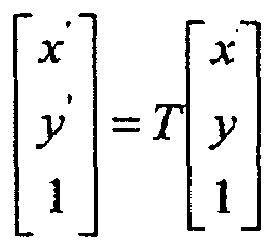
- After being developed:


- Where (x, y) is an original coordinate, and (x', y') is a transformed coordinate.
- Taking a combination of dividing by 32 and multiplying by 1.6 as an example, specifically, assuming there is a coordinate point (x 0, y 0), then a coordinate point (x 1, y 1) mapped into a drawing window may be obtained through a coordinate transformation as follows:


The above Equation indicates that a transformed coordinate value multiplied by 1.6 being divided by 32 may result in a error-free coordinate value in pixel. The transformed coordinate value multiplied by 1.6 may be obtained through the following transformation:
The above Equation indicates that the transformed coordinate value multiplied by 1.6 as required may be obtained through multiplying the scale factors, the twiddle factors and the shift factors of the transformation matrix respectively by 1.6 and then transforming the original coordinate with the matrix multiplied by 1.6. The above Equation also indicates that simply the transformation parameter instead of the original coordinate value is multiplied by 1.6 to thereby reduce a calculation effort. - As can be apparent from the developed transformation Equations, the transformation process is a process of consecutive multiplications and additions, including two multiplications and three additions. Particularly, a multiplication operation refers to a multiplication of a 32-bit integer with a fixed point number in the format of 16.16 and has a product of a fixed point number in the format of 48.16. Since a final transformation result is a 32-bit integer coordinate value, the product has to be shifted. In a RISC processor, a multiplication operation on two 32-bit integers results in a 64-bit integer, and the 64-bit integer is placed in HI and LO registers by placing the upper 32 bits in the HI register and the lower 32 bits in the LO register. Values in the HI and LO registers have to suffer from a shifting operation in order to obtain a 32-bit integer value. Typically, the upper 16 ones of the bits in the HI register are insignificant bits which may be dispensed with, the lower 16 ones of the bits in the LO register are a fractional part to be dispensed with, the lower 16 ones of the bits in the HI register are upper 16 bits of the 32-bit integer coordinate value, and the higher 16 ones of the bits in the LO register are lower 16 bits of the integer coordinate value. Therefore, the 32-bit integer coordinate value may result from the following manipulations on the HI and LO registers:
- HI<<16 HI is logically shifted by 16 bits to the left
- LO>>16 LO is logically shifted by 16 bits to the right
- R=HI | LO a bitwise OR operation is performed on HI and LO to obtain the result
- As can be apparent, the 32-bit integer coordinate value is result from three bit manipulations. However in the RISC processor, some complex manipulations may be performed with a single user-defined instruction, and the above manipulations may be performed with a UDI instruction, udi8 rs, rt, rd, (imm<<3), of the RISC processor. The UDI instruction is executed as follows:
- rd = {rs [(31-8*imm):0] , rt[31: (31-8*imm+1)]
- imm=00, 01,10,11,100
- In
Fig. 3 , ABCD represent contents in the register rs, where A = rs[31 : 24], B = rs[23 : 16], C = rs[15 : 8], D = rs[7 : 0]; EFGH represent contents in the register rt, where: E = rt[31 : 24], F = rt[23 : 16], G = rt[15 : 8], H = rt[7 : 0]; imm = 00 represents ABCD being fetched from the register rs and put sequentially into the register rd; imm =01 represents BCD being fetched from the register rs, E being fetched from the register rt and BCDE being put sequentially into the register rd; imm = 10 represents CD being fetched from the register rs, EF being fetched from the register rt and CDEF being put sequentially into the register rd; imm = 11 represents D being fetched from the register rs, EFG being fetched from the register rt and DEFG being put sequentially into the register rd; and imm = 100 represents EFGH being fetched from the register rt and put sequentially into the register rd. With this instruction, the HI register is taken as the register rs, and the LO register is taken as the register rt, and given imm = 10, then the lower 16 ones of the bits in the HI register and the upper 16 ones of the bits in the LO register may be fetched and combined into the 32-bit integer result as required. With the instruction, the above calculation is performed as follows: - udi8 HI,LO,R,(10)<<3
- In the embodiment of the invention, the single-cycle instruction, udi8 rs, rt, rd, (imm<<3), in UDIs may be executed to perform an operation in a single instruction instead of originally in three instructions, so as to reduce the number of instructions and also the number of cycles to execute the instructions, thereby accelerating the transformation process.
- In the above calculation process, the upper 16 ones of the bits in the HI register may also be significant bits, which indicate that the transformed coordinate value is so large that they exceed a range which can be represented with a 32-bit integer and an overflow occurs. In this case, the overflow needs to be handled typically by assigning an overflow transformation result with 0x7FFFFFF (overflow) or 0x80000000 (underflow). Whether the result overflows may be determined from whether the upper 16 ones of the bits in the HI register are significant bits. Specifically, when the highest one of the bits in the Hi register is 0, if all the upper 16 ones of the bits therein are 0, then there is no overflow; otherwise, there is an overflow, and the result is assigned with 0x7FFFFFFF and when the highest one of the bits in the Hi register is 1, if all the upper 16 ones of the bits therein are 1, then there is no underflow; otherwise, there is an underflow, and the result is assigned with 0x80000000.
- In the
operation 202, the original drawing window is updated into the new drawing coordinate system. -
Fig. 4a illustrates a position of a polygon relative to a drawing window before the shift factors are multiplied by the transformation parameter, and as illustrated inFig .4b , the position of the polygon relative to the drawing window is changed after the shift factors of the transformation matrix are multiplied by 1.6, thus resulting in an error in tailoring the polygon. In order to eliminate the tailor error, the drawing window is also updated correspondingly in an embodiment of the invention by transforming coordinates of four vertexes of the drawing window into those expressed in 1/20 pixel and then transforming each of the coordinate by using the following matrix:
Thus the polygon is tailored in the updated drawing window to eliminate any tailor error. - The
operation 203 will be detailed below. - After vertex coordinates are transformed, the polygon is mapped into the new drawing coordinate system. There are three positional relationships between the polygon and the new drawing window: the polygon is in the new drawing window, the polygon intersects the new drawing window, and the polygon is outside the new drawing window. For the polygon in the new drawing window, all the edges of the polygon are valid and thus they are valid boundaries of an area to be filled, in this case, no tailoring process is needed; for the polygon outside the new drawing window, all the edges of the polygon are invalid and thus enclose an area which needs not to be filled, in this case, the polygon is rejected directly without performing any subsequent process; and for the polygon intersecting the new drawing window, a part of the polygon is outside the new drawing window and needs not to be drawn, thus the polygon needs to be tailored with respect to the new drawing window, and in this respect, another part of the polygon in the new drawing window is calculated and then is filled.
- As illustrated in
Fig. 7 , an encircling rectangle refers to a smallest rectangle encircling vertexes of a polygon. In order to simplify a calculation process, a positional relationship between a polygon and a drawing window may be determined according to a derived encircling rectangle of the polygon in an embodiment of the invention, and then whether to perform a tailoring process may be determined according to the determined positional relationship, and if no tailoring is needed, then the polygon is acquired directly; otherwise, the polygon is tailored to acquire a part of the polygon in the new drawing window. - Determining whether to tailor the polygon according to the positional relationship between the encircling rectangle and the new drawing window is implemented as follows: when the encircling rectangle is in the new drawing window, it is determined that no tailoring is needed; and when the encircling rectangle intersects a part of the new drawing window, it is determined that the polygon needs to be tailored.
- Deriving a encircling rectangle of a polygon is a process of acquiring extremums of x and y coordinates of vertexes. The encircling rectangle may be derived through a way as follows.
- (1) Extremums of coordinates of vertexes of the polygon are acquired, i.e., maximum and minimum abscissas and ordinates among the vertex coordinates are acquired.
- x min = MIN(xi ).
- y min = MIN(yi )
- x max = MAX(xi )
- y max = MAX(yi ),i=1,...,N
- Where xi and yi are vertex coordinates of a polygon, and N is the number of vertexes of the polygon.
- (2) The encircling rectangle is delimited with (x min, y min) and (xmax , ymax ).
- After the encircling rectangle is derived, a positional relationship between the encircling rectangle and the new drawing window may result from a Boolean operation on the encircling rectangle and the rectangle of the new drawing window. The positional relationship is as illustrated in
Figs. 5a, 5b and 5c , where the encircling rectangle does not intersect the new drawing window inFig. 5a , the encircling rectangle intersects the new drawing window inFig. 5b , and the encircling rectangle is in the new drawing window inFig. 5c . In the case where the encircling rectangle does not intersect the new drawing window, the process is terminated; in the case where the encircling rectangle intersects the new drawing window, the polygon needs to be tailored; and in the case where the encircling rectangle is in the new drawing window, scanning and converting may be performed directly while skipping the tailoring process. - In the process, slopes of edges of the polygon are calculated for both tailoring operation and scanning and converting operation. In order to reduce the number of division operations, the slopes of edges of the polygon may be calculated only once to accommodate the use thereof during tailoring and scanning and converting. Therefore, the slopes of edges of the polygon are firstly calculated prior to tailoring and scanning and converting. In order to meet an application requirement, the calculated slopes are processed into fixed point numbers in the format of 16.16. A data structure as shown in Table 1 is filled during calculating the slopes:
Table 1 Edge x 1 y 1 x 2 y 2 slopex - Coordinates (x 1, y 1) and (x2, y 2) of both vertexes of an edge are taken among the transformed coordinates, and then the slope, Slopex , is calculated as follows:

- Then Slopex is processed into a fixed point number in the format of 16.16. When the edge is a horizontal edge, it is unable to calculate Slopex of the edge, but since the horizontal edge can be eliminated during scanning and converting process because it does not contribute to generation of scan segments during the scanning and converting progress, Slopex of the horizontal edge may be assigned with a fixed value, e.g., 0x7FFFFFFF, which indicates that this Slopex is insignificant and is not used for calculation. Finally, each value is written into the data structure for use in a subsequent process.
- A polygon may be tailored by acquiring a data structure, Edge, of each edge sequentially in the order of vertexes and then tailoring each edge sequentially with respect to the new drawing window in a tailoring algorithm to thereby resulting in a coordinate of a new vertex. When an edge is completely in the new drawing window, the coordinates of endpoints of the edge after tailoring and the Slopex keep unchanged. When an edge intersects a boundary of the new drawing window at one or two intersections, (x 1, y 1) or (x 2, y 2) is updated correspondingly with a calculated coordinate of the intersection(s) after tailoring under an update rule as illustrated in
Figs. 6a, 6b and 6c while Slopex keeps unchanged, where (x2, y2) is replaced with the coordinate of an intersection P1 inFig. 6a , (x1, y1) is replaced with the coordinate of an intersection P1 inFig. 6b , and (x1, y1) and (x2, y2) are replaced with the coordinates of intersections P1 and P2 respectively inFig.6c . - The slope, Slopex, of the edge is used in the tailoring algorithm and acquired directly from the data structure, Edge, for use. After the tailoring process is completed, the data structure, Edge, of each edge is updated so that all the edges of the polygon are in the new drawing window.
- The
operation 204 will be detailed below. - For a polygon already completely in the new drawing window, a scanning and converting process is thereafter performed to convert the polygon into a set of scan segments on each scan line. The scan line refers to a horizontal line in the drawing window traversing the window, and the total number of scan lines in a drawing window is H, i.e., the height of the drawing window in pixel. The scan segment refers to a part of the scan line in the polygon, and scan segments on a number, H, of scan lines completely cover the polygon. Thus, the polygon is colored by coloring these scan segments.
- In the scanning and converting process, edge data is acquired from the data structure, Edge, edges intersecting a current scan line are determined sequentially, and intersections of these edges with the scan line are calculated as follows:

- Where ix is a x coordinate value of a intersection of the scan line with a edge, and iy is the y coordinate value of the scan line. Since a horizontal edge does not contribute to generation of a scan segment, if an edge acquired from the data structure, Edge, is a horizontal edge, then the scanning and converting progress performed on the horizontal edge is skipped. A calculation process of the scanning and converting is as illustrated in
Fig. 8 . - After the calculation is completed, the x coordinates of a number, 2m+2 (m is a nonnegative integer), of resulting intersections are ranked in a descending order of the x coordinate value, and then are written into a data structure as shown in Table 2:
Table 2 ScanLine iy 

... 
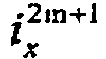
- Thus, it can be ensured that scan segments delimited with intersections, e.g.,


- It shall be noted that all the existing coordinate data is in 1/20 pixel, and to calculate an intersection, the coordinate y of a scan line also needs to be converted into one in 1/20 pixel, and if the coordinate y of the scan line is y', then the converted coordinate y of the scan line is represented as iy and iy = 20y'. In order to accelerate the scanning and converting process performed in the new drawing window, the scanning and converting is performed on only those scan lines with ordinates being an integer multiply of 2n in a preferred embodiments of the invention.
- This embodiment is implemented as follows:
- a link table of scan segments is created;
- when the ordinate of a scan line in the new drawing window is an integer multiply of 2n, a scan segment corresponding to the scan line is determined, which is a part of the scan line common with the part of the polygon in the new drawing coordinate system in the new drawing window; and
- parameters of the scan segment are added into the link table of scan segments.
- In the present embodiment, the parameters of the segment of the scan line common with the part of the polygon in the new drawing coordinate system in the new drawing window are added into the link table of scan segments. The parameters may include parameters in any combination selected from the group including: a combination of the ordinate iy of the scan line, the abscissa


- The operation 205 will be detailed below. After the scanning and converting process is completed, the scan segments

-
Fig. 9 illustrates a schematic diagram of a device for processing a vector graph according to an embodiment of the invention, and for a convenient description thereof, only parts thereof relevant to the embodiment of the invention are illustrated. The device may be integrated in a multimedia playing terminal, e.g., a mobile phone, a Personal Digital Assistant (PDA), an MP4, a navigator of a Global Positioning System (GPS), etc., to play multimedia data consisted of vectors, e.g., a FLASH animation file, a GPS image, etc. - Referring to
Fig. 9 , a device for processing a vector graph according to an embodiment of the invention includes aparsing unit 91, amapping unit 92, apolygon acquiring unit 93, a scanning and converting unit 94, a shiftingunit 95 and apixel coloring unit 96. - The parsing
unit 91 is configured to parse the vector graph into a series of polygons; - The
mapping unit 92 is configured to map the polygons into a new drawing coordinate system in 1/2n pixel by a transformation matrix multiplied with a transformation parameter, and to update an original drawing window into the new drawing coordinate system where the transformation parameter is represented as A and A = 2n/K, where n is a shift parameter, vertex coordinates of a polygon are in 1/K pixel, and n and K are natural numbers; - The
polygon acquiring unit 93 is configured to acquire, in a new drawing window, a part of each polygon in the new drawing coordinate system; - The scanning and converting unit 94 is configured to convert the part of the polygon in the new drawing coordinate system in the new drawing window into a set of scan segments;
- The shifting
unit 95 is configured to shifting true forms of coordinates of the scan segments by n bits to the right; and - The
pixel coloring unit 96 is configured to color pixels on shifted scan segments. - The
mapping unit 92 may map the polygons into the new drawing coordinate system in 1/2n pixel by the transformation parameter and the transformation matrix via the following formula:
- Particularly, the transformation matrix is represented as T and

- Further, the
mapping unit 92 may map the polygons into the new drawing coordinate system in 1/2n pixel by the transformation parameter and the transformation matrix in a single-cycle instruction among UDIs. In the embodiment of the invention, the single-cycle instruction, udi8 rs, rt, rd, (imm<<3), among the UDIs may be executed to perform an operation in a single instruction instead of originally in three instructions so as to reduce the number of instructions and also the number of cycles to execute the instructions, thereby accelerating the transformation process. - The device may further include:
- a slope calculation unit configured to calculate a slope of each edge of each of the polygons from vertex coordinates of the polygon in the new drawing coordinate system; and
- a memory unit configured to store the slope of each edge of the polygon to be provided for use in a tailoring process and a scanning and converting process.
- The
polygon acquiring unit 93 includes: - an encircling rectangle acquiring unit configured to acquire an encircling rectangle of each of the polygons; and
- a first acquiring unit configured to determine whether to tailor the polygon from a positional relationship between the encircling rectangle and the new drawing window, and to acquire directly the polygon if the polygon is not to be tailored; otherwise, to tailor the polygon to acquire a part of the polygon in the new drawing window.
- The first acquiring unit is configured to determine the polygon not to be tailored when the encircling rectangle is in the new drawing window and to determine the polygon to be tailored when the encircling rectangle intersects a part of the new drawing window.
- The first acquiring unit is configured to acquire a data structure of each edge sequentially, and to tailor the edge of a corresponding polygon with respect to the new drawing window in a tailoring algorithm, where, coordinates of endpoints of the edge keep unchanged after tailoring when the edge of the polygon is in the new drawing window, and a coordinate of an intersection is calculated after tailoring and coordinate values in the data structure are updated when the edge of the polygon intersects the new drawing window.
- The encircling rectangle acquiring unit is configured to acquire extremums among vertex coordinates of the polygon and to delimit the encircling rectangle with maximum and minimum abscissas and ordinates among the vertex coordinates.
- The scanning and converting unit 94 is configured to acquire a scan segment corresponding to a scan line in the new drawing window when the ordinate of the scan line is an integer multiply of 2n, where, the scan segment is a part of the scan line common with the part of the polygon in the new drawing coordinate system in the new drawing window.
- The scanning and converting unit 94 may acquire a scan segment corresponding to a scan line in the new drawing window when the ordinate of the scan line is an integer multiply of 2n in the following specific process:
- a link table of scan segments is created;
- when the ordinate of a scan line in the new drawing window is an integer multiply of 2n, a scan segment corresponding to the scan line are determined, which is a part of the scan line common with the part of the polygon in the new drawing coordinate system in the new drawing window; and
- parameters of the scan segment are added into the link table of scan segments.
- In the present embodiment, the parameters of each of the segments of the scan line common with the part of the polygon in the new drawing coordinate system in the new drawing window are added into the link table of scan segments. The parameters may include parameters in any combination selected from the group including: a combination of the ordinate iy of the scan line, the abscissa


- In the embodiments of the invention, when pixels covered by a scan line are being colored, a division operation is replaced with shifting of coordinate values, and a resulting error of tailoring a polygon is taken into consideration in a calculation process prior to coloring, thereby the number of division operations is reduced on the precondition of ensuring a correct result.
- The embodiments of the invention take into full consideration the characteristic of an RISC processor as well as the characteristic and computation association of a FLASH polygon processing, to well accelerate the FLASH polygon processing. Vertex coordinates of a polygon in FLASH are defined per 1/20 pixel, thus after scanning and converting process is completed, and during coloring of scan segments, coordinate values have to be divided by 20 into those expressed in pixel. Here, the operation of dividing by 20 is replaced with shifting by n bits to the right, and an error is taken into consideration in a transformation matrix, thereby ensuring reducing the number of division operations on the precondition of ensuring a correct result.
- In an embodiment of the invention, a specific UDI instruction may be executed to convert a result of a multiplication operation on fixed point numbers rapidly into an integer result as required, to thereby reduce the number of instructions required for conversion and accelerate the coordinate transformation process.
- In an embodiment of the invention, an encircling rectangle of a polygon is defined and a positional relationship between the encircling rectangle of the polygon and a new drawing window is calculated to decide whether the polygon needs to be tailored, so that only those polygons required to be tailored are tailored, thereby reducing unnecessary calculation. Since calculation of slopes of edges is required in both the tailoring process and the scanning and converting process, the slopes of the edges are calculated in advance for repeated use in the tailoring process and the scanning and converting process, to thereby reduce both the number of times that the slopes are calculated and the number of division operations.
- Evidently those skilled in the art may make various modifications and variations to the invention without departing from the scope of the invention. Accordingly, the invention is also intended to encompass these modifications and variations provided these modifications and variations come into the scope of the claims appended to the invention and their equivalents.
Claims (15)
- A method for rendering a geometric object given in a vector graphic format, wherein the vertex coordinates of the object are given in units of 1/K pixels, i.e. K units corresponding to one true pixel, the method comprising:parsing the geometric object into a series of polygons;transforming the vertex coordinates of the polygons into a new drawing coordinate system in which 2n units correspond to one true pixel, by using a transformation parameter and a transformation matrix, and transforming an original drawing window into the new drawing coordinate system, thereby generating a new drawing window, wherein the transformation parameter is represented by A = 2n/K,and wherein n and K are natural numbers > 1, and n unequal to K;mapping the relevant part of each of the polygons into the new drawing window;converting the parts of the polygons in the new drawing coordinate system in the new drawing window into a set of scan segments; andobtaining the true pixel coordinates by shifting the coordinates of the scan segments by n bits to the right, and coloring the pixels of the shifted scan segments.
- The method of claim 1, wherein, the vertex coordinates of the polygons are transformed into the new drawing coordinate system in which 2nunits correspond to one true pixel, by the transformation parameter and the transformation matrix via the following formula:

Wherein, the transformation matrix is represented by
- The method of claim 1 or 2, wherein, the vertex coordinates of the polygons are transformed into the new drawing coordinate system in which 2nunits correspond to one true pixel by the transformation parameter and the transformation matrix in a single-cycle instruction among user defined instructions.
- The method of claim 1, further comprising: before mapping the relevant part of each of the polygons into the new drawing window,
calculating and storing a slope of each edge of each of the polygons from vertex coordinates of the polygons in the new drawing coordinate system, wherein the slope of the each edge of the each of the polygons is stored for use in a tailoring process and a scanning and converting progress. - The method of claim 1 or 4, wherein, mapping the relevant part of each of the polygons into the new drawing window comprises:acquiring an encircling rectangle of each of the polygons in the new drawing coordinate system; anddetermining, for each polygon, whether the polygon needs to be tailored from a positional relationship between the encircling rectangle and the new drawing window, and acquiring directly the polygon if the polygon is not to be tailored; otherwise, tailoring the polygon to acquire a part of the polygon in the new drawing window;and wherein, determining, for each polygon, whether the polygon needs to be tailored from the positional relationship between the encircling rectangle and the new drawing window comprises:determining the polygon not be tailored when the encircling rectangle is in the new drawing window and determining the polygon to be tailored when the encircling rectangle intersects a part of the new drawing window.
- The method of claim 5, wherein, tailoring the polygon comprises:acquiring a data structure of each edge of the polygon sequentially, and tailoring the edge with respect to the new drawing window in a tailoring algorithm, wherein, when the edge of the polygon is in the new drawing window, coordinates of endpoints of the edge keep unchanged after tailoring; and when the edge of the polygon intersects the new drawing window, coordinates of an intersection are calculated after tailoring and coordinate values in the data structure are updated.
- The method of claim 5, wherein, acquiring the encircling rectangle of each of the polygon comprises:Acquiring, for each polygon, extremums among vertex coordinates of the polygon and delimiting the encircling rectangle with maximum and minimum abscissas and ordinates among the vertex coordinates.
- The method of claim 1, wherein, converting the parts of the polygons in the new drawing. coordinate system in the new drawing window into the set of scan segments comprises:acquiring a scan segment corresponding to a scan line in the new drawing window when an ordinate of the scan line is an integer multiply of 2n, wherein the scan segment is a part of the scan line common with the part of the polygon in the new drawing coordinate system in the new drawing window.
- A device for rendering a geometric object given in a vector graphic format, wherein the vertex coordinates of the object are given in units of 1/K pixels, i.e. K units corresponding to one true pixel, the device comprising:a parsing unit configured to parse the geometric object into a series of polygons;a mapping unit configured to transform the vertex coordinates of the polygons into a new drawing coordinate system in which 2n units correspond to one true pixel, by using a transformation matrix and a transformation parameter, and to transform an original drawing window into the new drawing coordinate system, thereby to generate a new drawing window, wherein the transformation parameter is represented by A = 2n/K, and wherein n and K are natural numbers> 1, and n unequal to K;a polygon acquiring unit configured to map the relevant part of each of the polygons into the new drawing window;a scanning and converting unit configured to convert the parts of the polygons in the new drawing coordinate system in the new drawing window into a set of scan segments;a shifting unit configured to obtain the true pixel coordinates by shifting the coordinates of the scan segments by n bits to the right; anda pixel coloring unit configured to color the pixels of the shifted scan segments.
- The device of claim 9, wherein, the mapping unit transforms the vertex coordinates of the polygons into the new drawing coordinate system in which 2n units correspond to one true pixel, by using the transformation parameter and the transformation matrix via the following formula:

Wherein, the transformation matrix is represented by
- The device of claim 9, further comprising:a slope calculation unit configured to calculate a slope of each edge of each of the polygons from vertex coordinates of the polygons in the new drawing coordinate system; anda memory unit configured to store the slope of the each edge of each of the polygons to be provided for use in a tailoring process and a scanning and converting process.
- The device of claim 9, wherein, the polygon acquiring unit comprises:an encircling rectangle acquiring unit configured to acquire an encircling rectangle of each of the polygons; anda first acquiring unit configured to determine, for each polygon, whether the polygon needs to be tailored from a positional relationship between the encircling rectangle and the new drawing window and to acquire directly the polygon if the polygon is not to be tailored; otherwise, to tailor the polygon to acquire a part of the polygon in the new drawing window;and wherein, the first acquiring unit is configured to determine the polygon not be tailored when the encircling rectangle is in the new drawing window and to determine the polygon to be tailored when the encircling rectangle intersects a part of the new drawing window.
- The device of claim 12, wherein, the first acquiring unit is configured to acquire, for each polygon, a data structure of each edge of the polygon sequentially, and to tailor the edge with respect to the new drawing window in a tailoring algorithm, wherein, when the edge of the polygon is in the new drawing window, coordinates of endpoints of the edge keep unchanged after tailoring; and when the edge of the polygon intersects the new drawing window, coordinates of an intersection are calculated after tailoring and coordinate values in the data structure are updated.
- The device of claim 12, wherein, the encircling rectangle acquiring unit is configured to acquire, for each polygon, extremums among vertex coordinates of the polygon and to delimit the encircling rectangle with maximum and minimum abscissas and ordinates among the vertex coordinates.
- The device of claim 9, wherein, the scanning and converting unit is configured to acquire a scan segment corresponding to a scan line in the new drawing window when an ordinate of the scan line is an integer multiply of 2n, wherein the scan segment is a part of the scan line common with the part of the polygon in the new drawing coordinate system in the new drawing window.
Applications Claiming Priority (2)
| Application Number | Priority Date | Filing Date | Title |
|---|---|---|---|
| CN200910203728.3A CN101923699B (en) | 2009-06-10 | 2009-06-10 | Method and device for reducing CPU consumption in vector graphics filling process |
| PCT/CN2010/073376 WO2010142208A1 (en) | 2009-06-10 | 2010-05-31 | Method and device for processing vector graphics |
Publications (3)
| Publication Number | Publication Date |
|---|---|
| EP2330560A1 EP2330560A1 (en) | 2011-06-08 |
| EP2330560A4 EP2330560A4 (en) | 2011-09-14 |
| EP2330560B1 true EP2330560B1 (en) | 2013-01-09 |
Family
ID=43308420
Family Applications (1)
| Application Number | Title | Priority Date | Filing Date |
|---|---|---|---|
| EP10785721A Active EP2330560B1 (en) | 2009-06-10 | 2010-05-31 | Method and device for processing vector graphics |
Country Status (4)
| Country | Link |
|---|---|
| US (1) | US9001127B2 (en) |
| EP (1) | EP2330560B1 (en) |
| CN (1) | CN101923699B (en) |
| WO (1) | WO2010142208A1 (en) |
Cited By (1)
| Publication number | Priority date | Publication date | Assignee | Title |
|---|---|---|---|---|
| RU2803880C1 (en) * | 2022-12-23 | 2023-09-21 | Общество с ограниченной ответственностью "ДубльГИС" | Method and device for map generalization |
Families Citing this family (11)
| Publication number | Priority date | Publication date | Assignee | Title |
|---|---|---|---|---|
| CN102651139B (en) * | 2012-04-28 | 2014-12-24 | 广东威创视讯科技股份有限公司 | Paint brush realizing method and device |
| CN103226619A (en) * | 2013-05-23 | 2013-07-31 | 北京邮电大学 | Native vector diagram format conversion method and system |
| US10395401B2 (en) | 2015-08-07 | 2019-08-27 | Zhejiang University | Method for efficient parallel visualizing vector graphic |
| CN107274482B (en) * | 2017-06-09 | 2020-01-10 | 大连海事大学 | Marine oil spill visualization and interaction method based on texture projection method |
| CN111145303B (en) * | 2019-12-26 | 2023-04-25 | 南京师范大学 | A method of drawing vector map line symbols with pointed arrows in consideration of line width consistency |
| CN111145295B (en) * | 2019-12-26 | 2023-05-09 | 南京师范大学 | Vector map line symbol half-dovetail arrow drawing method considering line width consistency |
| CN111639150B (en) * | 2020-06-02 | 2023-09-19 | 中国人民解放军陆军装甲兵学院 | A method and system for displaying details of an electronic map's enlarged area |
| CN112132928B (en) * | 2020-09-18 | 2024-06-28 | 网易(杭州)网络有限公司 | Vector diagram processing method, vector diagram processing device, electronic equipment and computer readable medium |
| CN112837328B (en) * | 2021-02-23 | 2022-06-03 | 中国石油大学(华东) | Rectangular window clipping and drawing method for two-dimensional polygonal primitive |
| CN116051627B (en) * | 2023-02-02 | 2023-06-13 | 杭州比智科技有限公司 | Method and system for realizing graphic self-adaption based on svg and Lottie |
| CN117875261B (en) * | 2024-03-13 | 2024-05-24 | 弈芯科技(杭州)有限公司 | Verification method and device for rectangular inclusion rule in integrated circuit layout verification |
Family Cites Families (6)
| Publication number | Priority date | Publication date | Assignee | Title |
|---|---|---|---|---|
| US5519823A (en) * | 1991-03-15 | 1996-05-21 | Hewlett-Packard Company | Apparatus for rendering antialiased vectors |
| US8269788B2 (en) * | 2005-11-15 | 2012-09-18 | Advanced Micro Devices Inc. | Vector graphics anti-aliasing |
| JP4643485B2 (en) * | 2006-03-30 | 2011-03-02 | 株式会社東芝 | Drawing apparatus, method and program |
| CN1862526A (en) * | 2006-06-21 | 2006-11-15 | 北京大学 | Discrete font generating method based on outline font technique |
| CN101211416B (en) * | 2006-12-26 | 2010-08-11 | 北京北大方正电子有限公司 | Boundary generation method, system and manufacturing method in vector graphics rasterization process |
| US20090033671A1 (en) * | 2007-08-02 | 2009-02-05 | Ati Technologies Ulc | Multi-sample rendering of 2d vector images |
-
2009
- 2009-06-10 CN CN200910203728.3A patent/CN101923699B/en active Active
-
2010
- 2010-05-31 US US13/254,399 patent/US9001127B2/en active Active
- 2010-05-31 WO PCT/CN2010/073376 patent/WO2010142208A1/en not_active Ceased
- 2010-05-31 EP EP10785721A patent/EP2330560B1/en active Active
Cited By (1)
| Publication number | Priority date | Publication date | Assignee | Title |
|---|---|---|---|---|
| RU2803880C1 (en) * | 2022-12-23 | 2023-09-21 | Общество с ограниченной ответственностью "ДубльГИС" | Method and device for map generalization |
Also Published As
| Publication number | Publication date |
|---|---|
| EP2330560A4 (en) | 2011-09-14 |
| WO2010142208A1 (en) | 2010-12-16 |
| US9001127B2 (en) | 2015-04-07 |
| EP2330560A1 (en) | 2011-06-08 |
| US20110316875A1 (en) | 2011-12-29 |
| CN101923699A (en) | 2010-12-22 |
| CN101923699B (en) | 2012-09-26 |
Similar Documents
| Publication | Publication Date | Title |
|---|---|---|
| US9001127B2 (en) | Method and device for processing vector graphics | |
| US8203564B2 (en) | Efficient 2-D and 3-D graphics processing | |
| US8749576B2 (en) | Method and system for implementing multiple high precision and low precision interpolators for a graphics pipeline | |
| US7872648B2 (en) | Random-access vector graphics | |
| US7190366B2 (en) | Method and system for a general instruction raster stage that generates programmable pixel packets | |
| US8421794B2 (en) | Processor with adaptive multi-shader | |
| EP2230642B1 (en) | Graphic drawing device and graphic drawing method | |
| US8018460B2 (en) | Vector graphics shape data generation apparatus, rendering apparatus, method, and program | |
| US10140736B2 (en) | Graphics processing systems | |
| US7098924B2 (en) | Method and programmable device for triangle interpolation in homogeneous space | |
| US8928667B2 (en) | Rendering stroked curves in graphics processing systems | |
| US20110285724A1 (en) | Conversion of dashed strokes into quadratic bèzier segment sequences | |
| JP2010113624A (en) | Device and method for drawing bezier curve and program | |
| CA2668563A1 (en) | Efficient scissoring for graphics application | |
| US7538773B1 (en) | Method and system for implementing parameter clamping to a valid range in a raster stage of a graphics pipeline | |
| US8040357B1 (en) | Quotient remainder coverage system and method | |
| US20030122829A1 (en) | Efficient movement of fragment stamp | |
| US8411105B1 (en) | Method and system for computing pixel parameters | |
| US8432394B1 (en) | Method and system for implementing clamped z value interpolation in a raster stage of a graphics pipeline | |
| JP4198098B2 (en) | Display device, program, and recording medium | |
| Morgan et al. | Hardware outline character rasterization | |
| Morgan et al. | An Asic for Outline Character Generation |
Legal Events
| Date | Code | Title | Description |
|---|---|---|---|
| PUAI | Public reference made under article 153(3) epc to a published international application that has entered the european phase |
Free format text: ORIGINAL CODE: 0009012 |
|
| 17P | Request for examination filed |
Effective date: 20110318 |
|
| AK | Designated contracting states |
Kind code of ref document: A1 Designated state(s): AL AT BE BG CH CY CZ DE DK EE ES FI FR GB GR HR HU IE IS IT LI LT LU LV MC MK MT NL NO PL PT RO SE SI SK SM TR |
|
| AX | Request for extension of the european patent |
Extension state: BA ME RS |
|
| RIC1 | Information provided on ipc code assigned before grant |
Ipc: G06T 11/40 20060101AFI20110802BHEP Ipc: G06T 11/20 20060101ALI20110802BHEP |
|
| A4 | Supplementary search report drawn up and despatched |
Effective date: 20110811 |
|
| 17Q | First examination report despatched |
Effective date: 20120330 |
|
| GRAP | Despatch of communication of intention to grant a patent |
Free format text: ORIGINAL CODE: EPIDOSNIGR1 |
|
| DAX | Request for extension of the european patent (deleted) | ||
| GRAS | Grant fee paid |
Free format text: ORIGINAL CODE: EPIDOSNIGR3 |
|
| GRAA | (expected) grant |
Free format text: ORIGINAL CODE: 0009210 |
|
| AK | Designated contracting states |
Kind code of ref document: B1 Designated state(s): AL AT BE BG CH CY CZ DE DK EE ES FI FR GB GR HR HU IE IS IT LI LT LU LV MC MK MT NL NO PL PT RO SE SI SK SM TR |
|
| REG | Reference to a national code |
Ref country code: GB Ref legal event code: FG4D |
|
| REG | Reference to a national code |
Ref country code: AT Ref legal event code: REF Ref document number: 593141 Country of ref document: AT Kind code of ref document: T Effective date: 20130115 Ref country code: CH Ref legal event code: EP |
|
| REG | Reference to a national code |
Ref country code: IE Ref legal event code: FG4D |
|
| REG | Reference to a national code |
Ref country code: DE Ref legal event code: R096 Ref document number: 602010004561 Country of ref document: DE Effective date: 20130307 |
|
| PG25 | Lapsed in a contracting state [announced via postgrant information from national office to epo] |
Ref country code: SI Free format text: LAPSE BECAUSE OF FAILURE TO SUBMIT A TRANSLATION OF THE DESCRIPTION OR TO PAY THE FEE WITHIN THE PRESCRIBED TIME-LIMIT Effective date: 20130109 |
|
| REG | Reference to a national code |
Ref country code: NL Ref legal event code: VDEP Effective date: 20130109 |
|
| REG | Reference to a national code |
Ref country code: AT Ref legal event code: MK05 Ref document number: 593141 Country of ref document: AT Kind code of ref document: T Effective date: 20130109 |
|
| REG | Reference to a national code |
Ref country code: LT Ref legal event code: MG4D |
|
| PG25 | Lapsed in a contracting state [announced via postgrant information from national office to epo] |
Ref country code: SE Free format text: LAPSE BECAUSE OF FAILURE TO SUBMIT A TRANSLATION OF THE DESCRIPTION OR TO PAY THE FEE WITHIN THE PRESCRIBED TIME-LIMIT Effective date: 20130109 Ref country code: BE Free format text: LAPSE BECAUSE OF FAILURE TO SUBMIT A TRANSLATION OF THE DESCRIPTION OR TO PAY THE FEE WITHIN THE PRESCRIBED TIME-LIMIT Effective date: 20130109 Ref country code: BG Free format text: LAPSE BECAUSE OF FAILURE TO SUBMIT A TRANSLATION OF THE DESCRIPTION OR TO PAY THE FEE WITHIN THE PRESCRIBED TIME-LIMIT Effective date: 20130409 Ref country code: ES Free format text: LAPSE BECAUSE OF FAILURE TO SUBMIT A TRANSLATION OF THE DESCRIPTION OR TO PAY THE FEE WITHIN THE PRESCRIBED TIME-LIMIT Effective date: 20130420 Ref country code: AT Free format text: LAPSE BECAUSE OF FAILURE TO SUBMIT A TRANSLATION OF THE DESCRIPTION OR TO PAY THE FEE WITHIN THE PRESCRIBED TIME-LIMIT Effective date: 20130109 Ref country code: LT Free format text: LAPSE BECAUSE OF FAILURE TO SUBMIT A TRANSLATION OF THE DESCRIPTION OR TO PAY THE FEE WITHIN THE PRESCRIBED TIME-LIMIT Effective date: 20130109 Ref country code: IS Free format text: LAPSE BECAUSE OF FAILURE TO SUBMIT A TRANSLATION OF THE DESCRIPTION OR TO PAY THE FEE WITHIN THE PRESCRIBED TIME-LIMIT Effective date: 20130509 Ref country code: NO Free format text: LAPSE BECAUSE OF FAILURE TO SUBMIT A TRANSLATION OF THE DESCRIPTION OR TO PAY THE FEE WITHIN THE PRESCRIBED TIME-LIMIT Effective date: 20130409 |
|
| PG25 | Lapsed in a contracting state [announced via postgrant information from national office to epo] |
Ref country code: PL Free format text: LAPSE BECAUSE OF FAILURE TO SUBMIT A TRANSLATION OF THE DESCRIPTION OR TO PAY THE FEE WITHIN THE PRESCRIBED TIME-LIMIT Effective date: 20130109 Ref country code: PT Free format text: LAPSE BECAUSE OF FAILURE TO SUBMIT A TRANSLATION OF THE DESCRIPTION OR TO PAY THE FEE WITHIN THE PRESCRIBED TIME-LIMIT Effective date: 20130509 Ref country code: LV Free format text: LAPSE BECAUSE OF FAILURE TO SUBMIT A TRANSLATION OF THE DESCRIPTION OR TO PAY THE FEE WITHIN THE PRESCRIBED TIME-LIMIT Effective date: 20130109 Ref country code: GR Free format text: LAPSE BECAUSE OF FAILURE TO SUBMIT A TRANSLATION OF THE DESCRIPTION OR TO PAY THE FEE WITHIN THE PRESCRIBED TIME-LIMIT Effective date: 20130410 Ref country code: NL Free format text: LAPSE BECAUSE OF FAILURE TO SUBMIT A TRANSLATION OF THE DESCRIPTION OR TO PAY THE FEE WITHIN THE PRESCRIBED TIME-LIMIT Effective date: 20130109 Ref country code: FI Free format text: LAPSE BECAUSE OF FAILURE TO SUBMIT A TRANSLATION OF THE DESCRIPTION OR TO PAY THE FEE WITHIN THE PRESCRIBED TIME-LIMIT Effective date: 20130109 |
|
| PG25 | Lapsed in a contracting state [announced via postgrant information from national office to epo] |
Ref country code: HR Free format text: LAPSE BECAUSE OF FAILURE TO SUBMIT A TRANSLATION OF THE DESCRIPTION OR TO PAY THE FEE WITHIN THE PRESCRIBED TIME-LIMIT Effective date: 20130109 |
|
| PG25 | Lapsed in a contracting state [announced via postgrant information from national office to epo] |
Ref country code: CZ Free format text: LAPSE BECAUSE OF FAILURE TO SUBMIT A TRANSLATION OF THE DESCRIPTION OR TO PAY THE FEE WITHIN THE PRESCRIBED TIME-LIMIT Effective date: 20130109 Ref country code: DK Free format text: LAPSE BECAUSE OF FAILURE TO SUBMIT A TRANSLATION OF THE DESCRIPTION OR TO PAY THE FEE WITHIN THE PRESCRIBED TIME-LIMIT Effective date: 20130109 Ref country code: SK Free format text: LAPSE BECAUSE OF FAILURE TO SUBMIT A TRANSLATION OF THE DESCRIPTION OR TO PAY THE FEE WITHIN THE PRESCRIBED TIME-LIMIT Effective date: 20130109 Ref country code: RO Free format text: LAPSE BECAUSE OF FAILURE TO SUBMIT A TRANSLATION OF THE DESCRIPTION OR TO PAY THE FEE WITHIN THE PRESCRIBED TIME-LIMIT Effective date: 20130109 Ref country code: EE Free format text: LAPSE BECAUSE OF FAILURE TO SUBMIT A TRANSLATION OF THE DESCRIPTION OR TO PAY THE FEE WITHIN THE PRESCRIBED TIME-LIMIT Effective date: 20130109 |
|
| PLBE | No opposition filed within time limit |
Free format text: ORIGINAL CODE: 0009261 |
|
| STAA | Information on the status of an ep patent application or granted ep patent |
Free format text: STATUS: NO OPPOSITION FILED WITHIN TIME LIMIT |
|
| PG25 | Lapsed in a contracting state [announced via postgrant information from national office to epo] |
Ref country code: CY Free format text: LAPSE BECAUSE OF FAILURE TO SUBMIT A TRANSLATION OF THE DESCRIPTION OR TO PAY THE FEE WITHIN THE PRESCRIBED TIME-LIMIT Effective date: 20130109 |
|
| 26N | No opposition filed |
Effective date: 20131010 |
|
| PG25 | Lapsed in a contracting state [announced via postgrant information from national office to epo] |
Ref country code: IT Free format text: LAPSE BECAUSE OF FAILURE TO SUBMIT A TRANSLATION OF THE DESCRIPTION OR TO PAY THE FEE WITHIN THE PRESCRIBED TIME-LIMIT Effective date: 20130109 Ref country code: MC Free format text: LAPSE BECAUSE OF FAILURE TO SUBMIT A TRANSLATION OF THE DESCRIPTION OR TO PAY THE FEE WITHIN THE PRESCRIBED TIME-LIMIT Effective date: 20130109 |
|
| REG | Reference to a national code |
Ref country code: DE Ref legal event code: R097 Ref document number: 602010004561 Country of ref document: DE Effective date: 20131010 |
|
| REG | Reference to a national code |
Ref country code: IE Ref legal event code: MM4A |
|
| PG25 | Lapsed in a contracting state [announced via postgrant information from national office to epo] |
Ref country code: IE Free format text: LAPSE BECAUSE OF NON-PAYMENT OF DUE FEES Effective date: 20130531 |
|
| REG | Reference to a national code |
Ref country code: CH Ref legal event code: PL |
|
| GBPC | Gb: european patent ceased through non-payment of renewal fee |
Effective date: 20140531 |
|
| PG25 | Lapsed in a contracting state [announced via postgrant information from national office to epo] |
Ref country code: LI Free format text: LAPSE BECAUSE OF NON-PAYMENT OF DUE FEES Effective date: 20140531 Ref country code: CH Free format text: LAPSE BECAUSE OF NON-PAYMENT OF DUE FEES Effective date: 20140531 |
|
| PG25 | Lapsed in a contracting state [announced via postgrant information from national office to epo] |
Ref country code: MT Free format text: LAPSE BECAUSE OF FAILURE TO SUBMIT A TRANSLATION OF THE DESCRIPTION OR TO PAY THE FEE WITHIN THE PRESCRIBED TIME-LIMIT Effective date: 20130109 |
|
| REG | Reference to a national code |
Ref country code: FR Ref legal event code: PLFP Year of fee payment: 6 |
|
| PG25 | Lapsed in a contracting state [announced via postgrant information from national office to epo] |
Ref country code: SM Free format text: LAPSE BECAUSE OF FAILURE TO SUBMIT A TRANSLATION OF THE DESCRIPTION OR TO PAY THE FEE WITHIN THE PRESCRIBED TIME-LIMIT Effective date: 20130109 Ref country code: GB Free format text: LAPSE BECAUSE OF NON-PAYMENT OF DUE FEES Effective date: 20140531 |
|
| PG25 | Lapsed in a contracting state [announced via postgrant information from national office to epo] |
Ref country code: TR Free format text: LAPSE BECAUSE OF FAILURE TO SUBMIT A TRANSLATION OF THE DESCRIPTION OR TO PAY THE FEE WITHIN THE PRESCRIBED TIME-LIMIT Effective date: 20130109 |
|
| PG25 | Lapsed in a contracting state [announced via postgrant information from national office to epo] |
Ref country code: MK Free format text: LAPSE BECAUSE OF FAILURE TO SUBMIT A TRANSLATION OF THE DESCRIPTION OR TO PAY THE FEE WITHIN THE PRESCRIBED TIME-LIMIT Effective date: 20130109 Ref country code: HU Free format text: LAPSE BECAUSE OF FAILURE TO SUBMIT A TRANSLATION OF THE DESCRIPTION OR TO PAY THE FEE WITHIN THE PRESCRIBED TIME-LIMIT; INVALID AB INITIO Effective date: 20100531 Ref country code: LU Free format text: LAPSE BECAUSE OF NON-PAYMENT OF DUE FEES Effective date: 20130531 |
|
| REG | Reference to a national code |
Ref country code: DE Ref legal event code: R082 Ref document number: 602010004561 Country of ref document: DE Representative=s name: DENNEMEYER & ASSOCIATES S.A., DE Ref country code: DE Ref legal event code: R081 Ref document number: 602010004561 Country of ref document: DE Owner name: ACTIONS (ZHUHAI) TECHNOLOGY CO., LIMITED, CN Free format text: FORMER OWNER: ACTIONS SEMICONDUCTOR CO., LTD., GUANGDONG, CN |
|
| REG | Reference to a national code |
Ref country code: FR Ref legal event code: PLFP Year of fee payment: 7 |
|
| REG | Reference to a national code |
Ref country code: FR Ref legal event code: TP Owner name: ACTIONS (ZHUHAI) TECHNOLOGY CO., LIMITED, CN Effective date: 20160523 Ref country code: FR Ref legal event code: CA Effective date: 20160523 |
|
| REG | Reference to a national code |
Ref country code: FR Ref legal event code: PLFP Year of fee payment: 8 |
|
| REG | Reference to a national code |
Ref country code: FR Ref legal event code: PLFP Year of fee payment: 9 |
|
| PG25 | Lapsed in a contracting state [announced via postgrant information from national office to epo] |
Ref country code: AL Free format text: LAPSE BECAUSE OF FAILURE TO SUBMIT A TRANSLATION OF THE DESCRIPTION OR TO PAY THE FEE WITHIN THE PRESCRIBED TIME-LIMIT Effective date: 20130109 |
|
| REG | Reference to a national code |
Ref country code: DE Ref legal event code: R082 Ref document number: 602010004561 Country of ref document: DE Representative=s name: DENNEMEYER & ASSOCIATES RECHTSANWALTSGESELLSCH, DE Ref country code: DE Ref legal event code: R082 Ref document number: 602010004561 Country of ref document: DE Representative=s name: DENNEMEYER & ASSOCIATES S.A., DE Ref country code: DE Ref legal event code: R081 Ref document number: 602010004561 Country of ref document: DE Owner name: ACTIONS TECHNOLOGY CO., LTD., CN Free format text: FORMER OWNER: ACTIONS (ZHUHAI) TECHNOLOGY CO., LIMITED, ZHUHAI, CN |
|
| REG | Reference to a national code |
Ref country code: DE Ref legal event code: R082 Ref document number: 602010004561 Country of ref document: DE Representative=s name: DENNEMEYER & ASSOCIATES RECHTSANWALTSGESELLSCH, DE |
|
| PGFP | Annual fee paid to national office [announced via postgrant information from national office to epo] |
Ref country code: DE Payment date: 20260513 Year of fee payment: 17 |
|
| PGFP | Annual fee paid to national office [announced via postgrant information from national office to epo] |
Ref country code: FR Payment date: 20260528 Year of fee payment: 17 |