EP2330281A1 - Gas turbine device - Google Patents
Gas turbine device Download PDFInfo
- Publication number
- EP2330281A1 EP2330281A1 EP08877149A EP08877149A EP2330281A1 EP 2330281 A1 EP2330281 A1 EP 2330281A1 EP 08877149 A EP08877149 A EP 08877149A EP 08877149 A EP08877149 A EP 08877149A EP 2330281 A1 EP2330281 A1 EP 2330281A1
- Authority
- EP
- European Patent Office
- Prior art keywords
- gas
- mixed
- hydrogen
- mixed gas
- turbine device
- Prior art date
- Legal status (The legal status is an assumption and is not a legal conclusion. Google has not performed a legal analysis and makes no representation as to the accuracy of the status listed.)
- Granted
Links
Images

Classifications
-
- F—MECHANICAL ENGINEERING; LIGHTING; HEATING; WEAPONS; BLASTING
- F02—COMBUSTION ENGINES; HOT-GAS OR COMBUSTION-PRODUCT ENGINE PLANTS
- F02C—GAS-TURBINE PLANTS; AIR INTAKES FOR JET-PROPULSION PLANTS; CONTROLLING FUEL SUPPLY IN AIR-BREATHING JET-PROPULSION PLANTS
- F02C3/00—Gas-turbine plants characterised by the use of combustion products as the working fluid
- F02C3/20—Gas-turbine plants characterised by the use of combustion products as the working fluid using a special fuel, oxidant, or dilution fluid to generate the combustion products
-
- F—MECHANICAL ENGINEERING; LIGHTING; HEATING; WEAPONS; BLASTING
- F02—COMBUSTION ENGINES; HOT-GAS OR COMBUSTION-PRODUCT ENGINE PLANTS
- F02C—GAS-TURBINE PLANTS; AIR INTAKES FOR JET-PROPULSION PLANTS; CONTROLLING FUEL SUPPLY IN AIR-BREATHING JET-PROPULSION PLANTS
- F02C3/00—Gas-turbine plants characterised by the use of combustion products as the working fluid
- F02C3/20—Gas-turbine plants characterised by the use of combustion products as the working fluid using a special fuel, oxidant, or dilution fluid to generate the combustion products
- F02C3/22—Gas-turbine plants characterised by the use of combustion products as the working fluid using a special fuel, oxidant, or dilution fluid to generate the combustion products the fuel or oxidant being gaseous at standard temperature and pressure
-
- F—MECHANICAL ENGINEERING; LIGHTING; HEATING; WEAPONS; BLASTING
- F02—COMBUSTION ENGINES; HOT-GAS OR COMBUSTION-PRODUCT ENGINE PLANTS
- F02C—GAS-TURBINE PLANTS; AIR INTAKES FOR JET-PROPULSION PLANTS; CONTROLLING FUEL SUPPLY IN AIR-BREATHING JET-PROPULSION PLANTS
- F02C3/00—Gas-turbine plants characterised by the use of combustion products as the working fluid
- F02C3/20—Gas-turbine plants characterised by the use of combustion products as the working fluid using a special fuel, oxidant, or dilution fluid to generate the combustion products
- F02C3/26—Gas-turbine plants characterised by the use of combustion products as the working fluid using a special fuel, oxidant, or dilution fluid to generate the combustion products the fuel or oxidant being solid or pulverulent, e.g. in slurry or suspension
- F02C3/28—Gas-turbine plants characterised by the use of combustion products as the working fluid using a special fuel, oxidant, or dilution fluid to generate the combustion products the fuel or oxidant being solid or pulverulent, e.g. in slurry or suspension using a separate gas producer for gasifying the fuel before combustion
-
- F—MECHANICAL ENGINEERING; LIGHTING; HEATING; WEAPONS; BLASTING
- F02—COMBUSTION ENGINES; HOT-GAS OR COMBUSTION-PRODUCT ENGINE PLANTS
- F02C—GAS-TURBINE PLANTS; AIR INTAKES FOR JET-PROPULSION PLANTS; CONTROLLING FUEL SUPPLY IN AIR-BREATHING JET-PROPULSION PLANTS
- F02C3/00—Gas-turbine plants characterised by the use of combustion products as the working fluid
- F02C3/20—Gas-turbine plants characterised by the use of combustion products as the working fluid using a special fuel, oxidant, or dilution fluid to generate the combustion products
- F02C3/30—Adding water, steam or other fluids for influencing combustion, e.g. to obtain cleaner exhaust gases
-
- F—MECHANICAL ENGINEERING; LIGHTING; HEATING; WEAPONS; BLASTING
- F02—COMBUSTION ENGINES; HOT-GAS OR COMBUSTION-PRODUCT ENGINE PLANTS
- F02C—GAS-TURBINE PLANTS; AIR INTAKES FOR JET-PROPULSION PLANTS; CONTROLLING FUEL SUPPLY IN AIR-BREATHING JET-PROPULSION PLANTS
- F02C6/00—Plural gas-turbine plants; Combinations of gas-turbine plants with other apparatus; Adaptations of gas-turbine plants for special use
-
- F—MECHANICAL ENGINEERING; LIGHTING; HEATING; WEAPONS; BLASTING
- F02—COMBUSTION ENGINES; HOT-GAS OR COMBUSTION-PRODUCT ENGINE PLANTS
- F02C—GAS-TURBINE PLANTS; AIR INTAKES FOR JET-PROPULSION PLANTS; CONTROLLING FUEL SUPPLY IN AIR-BREATHING JET-PROPULSION PLANTS
- F02C7/00—Features, components parts, details or accessories, not provided for in, or of interest apart form groups F02C1/00 - F02C6/00; Air intakes for jet-propulsion plants
- F02C7/22—Fuel supply systems
-
- F—MECHANICAL ENGINEERING; LIGHTING; HEATING; WEAPONS; BLASTING
- F02—COMBUSTION ENGINES; HOT-GAS OR COMBUSTION-PRODUCT ENGINE PLANTS
- F02C—GAS-TURBINE PLANTS; AIR INTAKES FOR JET-PROPULSION PLANTS; CONTROLLING FUEL SUPPLY IN AIR-BREATHING JET-PROPULSION PLANTS
- F02C7/00—Features, components parts, details or accessories, not provided for in, or of interest apart form groups F02C1/00 - F02C6/00; Air intakes for jet-propulsion plants
- F02C7/22—Fuel supply systems
- F02C7/236—Fuel delivery systems comprising two or more pumps
-
- F—MECHANICAL ENGINEERING; LIGHTING; HEATING; WEAPONS; BLASTING
- F02—COMBUSTION ENGINES; HOT-GAS OR COMBUSTION-PRODUCT ENGINE PLANTS
- F02C—GAS-TURBINE PLANTS; AIR INTAKES FOR JET-PROPULSION PLANTS; CONTROLLING FUEL SUPPLY IN AIR-BREATHING JET-PROPULSION PLANTS
- F02C9/00—Controlling gas-turbine plants; Controlling fuel supply in air- breathing jet-propulsion plants
- F02C9/26—Control of fuel supply
- F02C9/40—Control of fuel supply specially adapted to the use of a special fuel or a plurality of fuels
-
- Y—GENERAL TAGGING OF NEW TECHNOLOGICAL DEVELOPMENTS; GENERAL TAGGING OF CROSS-SECTIONAL TECHNOLOGIES SPANNING OVER SEVERAL SECTIONS OF THE IPC; TECHNICAL SUBJECTS COVERED BY FORMER USPC CROSS-REFERENCE ART COLLECTIONS [XRACs] AND DIGESTS
- Y02—TECHNOLOGIES OR APPLICATIONS FOR MITIGATION OR ADAPTATION AGAINST CLIMATE CHANGE
- Y02E—REDUCTION OF GREENHOUSE GAS [GHG] EMISSIONS, RELATED TO ENERGY GENERATION, TRANSMISSION OR DISTRIBUTION
- Y02E20/00—Combustion technologies with mitigation potential
- Y02E20/16—Combined cycle power plant [CCPP], or combined cycle gas turbine [CCGT]
Definitions
- the present invention relates to a gas turbine device which uses a mixed gas obtained by mixing together three or more types of gases as a fuel gas for a combustor.
- a gas turbine device dedicated to low calorie gas combustion which is capable of using multiple types of low calorie gases with different calories at the same time is generally known as an example of a gas turbine device which uses a mixed gas obtained by mixing together three or more types of gases as a fuel gas for a combustor.
- the gas turbine device dedicated to low calorie gas combustion is used, for example, in a steel mill.
- various excessive gases such as a blast furnace gas (B gas), a coke oven gas (C gas), and a converter gas (L gas) are produced in a manufacturing process of a steel product.
- B gas blast furnace gas
- C gas coke oven gas
- L gas converter gas
- a gas turbine device disclosed in Patent Document 1 listed below is given as a specific example of the gas turbine device which uses the mixed gas of multiple types of excessive gases and the natural gas as the fuel gas for a combustor.
- the blast furnace gas, the coke oven gas, and the natural gas are mixed by a mixer 51, and this mixed gas is supplied to a combustor of a gas turbine 52 as the fuel gas.
- Patent Document 2 is also given as a prior art document related to the present invention.
- Patent Document 2 discloses an example of a gas turbine device which reuses part of a combustion gas exhausted from a gas turbine by supplying the part of the combustion gas to an air compressor.
- an object of the present invention is to provide a gas turbine device capable of producing a mixed gas in which three or more types of gases (for example, three or more types of gases from any of single gases such as a butane gas and a propane gas and gases in which multiple types of gases are mixed such as a blast furnace gas and a converter gas) are evenly mixed and also of preventing an explosion by monitoring a hydrogen concentration and an oxygen concentration in the mixed gas.
- three or more types of gases for example, three or more types of gases from any of single gases such as a butane gas and a propane gas and gases in which multiple types of gases are mixed such as a blast furnace gas and a converter gas
- a gas turbine device of a first invention for solving the above problem provides a gas turbine device configured to burn in a combustor a fuel gas supplied from a fuel gas supplier, together with a compressed air supplied from an air compressor, and to rotationally drive a gas turbine by a combustion gas generated at the burning, the gas turbine device characterized in that the fuel gas supplier includes a plurality of mixers, and is configured to produce a mixed gas by mixing three or more types of gases in the mixers in ascending order of specific gravity or in descending order of specific gravity, and to supply the mixed gas to the combustor as the fuel gas.
- a gas turbine device of a third invention provides the gas turbine device of the second invention characterized in that the diluent gas mixer is configured to mix, into the mixed gas, part of the combustion gas exhausted from the gas turbine as the diluent gas.
- a gas turbine device of a fourth invention provides the gas turbine device of the first invention characterized in that the fuel gas supplier is configured to include a remixer that performs remixing by agitating the mixed gas.
- a gas turbine device of a seventh invention provides the gas turbine device of any one of the second, fifth and sixth inventions characterized in that the fuel gas supplier is configured to perform any of the mixing of the diluent gas by the diluent gas mixer, the remixing of the mixed gas by the remixer, and the discharge of the mixed gas by the emergency discharge valve at a position downstream of the hydrogen/oxygen sensor.
- a gas turbine device of an eighth invention provides the gas turbine device of any one of the second to seventh inventions characterized by further comprising a gas compressor that compresses the mixed gas and supplies the mixed gas thus compressed to the combustor, the gas turbine device characterized in that the fuel gas supplier is configured to perform any of the mixing of the diluent gas by the diluent gas mixer, the remixing of the mixed gas by the remixer, and the discharge of the mixed gas by the emergency discharge valve at a position upstream of the gas compressor.
- the gas turbine device of the first invention provides a gas turbine device configured to burn in a combustor a fuel gas supplied from a fuel gas supplier, together with a compressed air supplied from an air compressor, and to rotationally drive a gas turbine by a combustion gas generated at the burning, the gas turbine device characterized in that the fuel gas supplier includes a plurality of mixers, and is configured to produce a mixed gas by mixing three or more types of gases in the mixers in ascending order of specific gravity or in descending order of specific gravity, and to supply the mixed gas to the combustor as the fuel gas. Accordingly, gases with similar specific gravities are mixed sequentially in both cases of mixing in ascending order of specific gravity and of mixing in descending order of specific gravity. This allows production of the mixed gas in which three or more types of gases are evenly mixed. When this evenly mixed gas is used as the fuel gas for the combustor, occurrence of uneven combustion is prevented and stable combustion is made possible.
- the gas turbine device of the second invention provides the gas turbine device of the first invention characterized in that the fuel gas supplier is configured to include: a hydrogen/oxygen sensor that detects a hydrogen concentration and an oxygen concentration in the mixed gas; a diluent gas mixer that mixes, into the mixed gas, a diluent gas for diluting the hydrogen concentration and the oxygen concentration; and a controller that causes the diluent gas mixer to operate to mix the diluent gas into the mixed gas when the hydrogen concentration and the oxygen concentration detected by the hydrogen/oxygen sensor become equal to or more than a set value.
- the fuel gas supplier is configured to include: a hydrogen/oxygen sensor that detects a hydrogen concentration and an oxygen concentration in the mixed gas; a diluent gas mixer that mixes, into the mixed gas, a diluent gas for diluting the hydrogen concentration and the oxygen concentration; and a controller that causes the diluent gas mixer to operate to mix the diluent gas into the mixed gas when the hydrogen concentration and the oxygen concentration
- the hydrogen concentration and the oxygen concentration in the mixed gas are equal to or more than the set value, and to dilute and reduce the hydrogen concentration and the oxygen concentration of the mixed gas with the diluent gas before the mixed gas with the high hydrogen concentration and oxygen concentration is supplied to the combustor.
- the hydrogen concentration and the oxygen concentration in the mixed gas are suppressed to concentrations equal to or lower than the explosion limit, and the gas turbine device can be operated safely.
- the gas turbine device of the third invention provides the gas turbine device of the second invention characterized in that the diluent gas mixer is configured to mix, into the mixed gas, part of the combustion gas exhausted from the gas turbine as the diluent gas. Accordingly, the combustion gas is effectively used as the diluent gas, and there is no need for a nitrogen gas or the like. Thus, an efficient and inexpensive gas turbine device can be achieved.
- the gas turbine device of the fourth invention provides the gas turbine device of the first invention characterized in that the fuel gas supplier is configured to include a remixer that performs remixing by agitating the mixed gas. Accordingly, even when hydrogen and oxygen in the mixed gas are released and hydrogen collection and oxygen collection are generated (gravity separation occurs), it is possible to achieve an evenly mixed state again by performing remixing by agitating the mixed gas with the remixer before the mixed gas is supplied to the combustor. Thus, the risk of an explosion is reduced, and the gas turbine device can be operated safely.
- the gas turbine device of the fifth invention provides the gas turbine device of the fourth invention characterized in that the fuel gas supplier is configured to include: a hydrogen/oxygen sensor that detects a hydrogen concentration and an oxygen concentration in the mixed gas; and a controller that causes the remixer to operate to remix the mixed gas when the hydrogen concentration and the oxygen concentration detected by the hydrogen/oxygen sensor become equal to or more than a set value.
- the gas turbine device of the sixth invention provides the gas turbine device of the first invention characterized in that the fuel gas supplier is configured to include: a hydrogen/oxygen sensor that detects a hydrogen concentration and an oxygen concentration in the mixed gas; an emergency discharge valve; and a controller that causes the emergency discharge valve to operate to discharge the mixed gas when the hydrogen concentration and the oxygen concentration detected by the hydrogen/oxygen sensor become equal to or more than a set value. Accordingly, even when hydrogen and oxygen in the mixed gas a are released and hydrogen collection and oxygen collection are generated thereby causing an increase in the hydrogen concentration and the oxygen concentration of the mixed gas, it is possible to detect that the hydrogen concentration and the oxygen concentration in the mixed gas are equal to or more than the set value, and to discharge the mixed gas before the mixed gas is supplied to the combustor. Thus, the risk of an explosion is reduced, and the gas turbine device can be operated safely.
- the fuel gas supplier is configured to include: a hydrogen/oxygen sensor that detects a hydrogen concentration and an oxygen concentration in the mixed gas; an emergency discharge valve; and a controller
- the gas turbine device of the seventh invention provides the gas turbine device of any one of the second, fifth and sixth inventions characterized in that the fuel gas supplier is configured to perform any of the mixing of the diluent gas by the diluent gas mixer, the remixing of the mixed gas by the remixer, and the discharge of the mixed gas by the emergency discharge valve at a position downstream of the hydrogen/oxygen sensor. Accordingly, the mixed gas with high hydrogen concentration and oxygen concentration which is detected by the hydrogen/oxygen sensor on an upstream side can be surely mixed with the diluent gas by the diluent gas mixer, remixed by the remixer, or discharged by the emergency discharge valve on a downstream side.
- the gas turbine device of the eighth invention provides the gas turbine device of any one of the second to seventh inventions characterized by further comprising a gas compressor that compresses the mixed gas and supplies the mixed gas thus compressed to the combustor, the gas turbine device characterized in that the fuel gas supplier is configured to perform any of the mixing of the diluent gas by the diluent gas mixer, the remixing of the mixed gas by the remixer, and the discharge of the mixed gas by the emergency discharge valve at a position upstream of the gas compressor. Accordingly, the mixed gas with high hydrogen concentration and oxygen concentration is mixed with the diluent gas by the diluent gas mixer, remixed by the remixer, or discharged by the emergency discharge valve before flowing into the gas compressor. Thus, the risk of an explosion can be surly reduced also in the gas turbine device with the gas compressor.
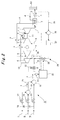
- Fig. 1 is a configuration diagram of a gas turbine device according to Embodiment 1 of the present invention.
- the gas turbine device of Embodiment 1 is a combined cycle power generating device which generates electric power by causing a gas turbine and a steam turbine to operate.
- the gas turbine device includes a gas turbine 1, a steam turbine 5, a combustor 2, an air compressor 3, an electrical generator 4, a gas compressor 6, an exhaust heat recovery boiler 7, and a fuel gas supplier 8.
- a mixed gas a produced in the fuel gas supplier 8 flows into the gas compressor 6 through a fuel supply line 9, and is compressed there. Thereafter, the compressed mixed gas a is supplied to the combustor 2 through a fuel supply line 10 as a fuel gas.
- the fuel gas (mixed gas a) supplied from the fuel gas supplier 8 is burned together with a compressed air b supplied from the air compressor 3.
- a combustion gas c produced at the burning is supplied to the gas turbine 1 to rotationally drive the gas turbine 1.
- the combustion gas (exhaust gas) c exhausted from the gas turbine 1 flows through an exhaust line (flue) 12. Then, heat is recovered from the combustion gas c via the heat exchange with a feed water d in the exhaust heat recovery boiler 7 provided to the exhaust line 12. Thereafter, the combustion gas c is dissipated from a stack 13. Meanwhile, the feed water d is heated due to the heat exchange with the combustion gas (exhaust gas) c, and turns into a steam e in the exhaust heat recovery boiler 7. This steam e is supplied to the steam turbine 5 through a steam line 14, and thus the steam turbine 5 is rotationally driven. The steam e exhausted from the steam turbine 5 is condensed in an unillustrated condenser, and is reused as the feed water d.
- the gas turbine 1, the steam turbine 5, the air compressor 3, the electrical generator 4, and the gas compressor 6 are disposed on the same rotary shaft 11.
- the air compressor 3, the electrical generator 4, and the gas compressor 6 are rotationally driven by the gas turbine 1 and the steam turbine 5. Accordingly, the air compressor 3 takes in and compresses an outside air (air) g, and supplies this compressed air b to the combustor 2 as described above.
- the electrical generator 4 generates electric power, and transmits this generated electric power to unillustrated power systems inside a steel mill and outside the steel mill.
- the gas compressor 6 takes in and compresses the mixed gas a, and supplies this compressed mixed gas a to the combustor 2 as described above.
- the fuel gas supplier 8 which is a characteristic feature of Embodiment 1, includes two mixers 15, 16. By use of these mixers 15, 16, three types of gases of a first gas I, a second gas II, and a third gas III are mixed in ascending order of specific gravity or in descending order of specific gravity, and thus the mixed gas a is produced. Then, the fuel gas supplier 8 supplies this mixed gas a to the combustor 2 through the gas compressor 6 as described above.
- an inlet side of the first mixer 15 is connected to a downstream end of a fuel supply line 18 provided with a flow regulating valve 17 and also to a downstream end of a fuel supply line 20 provided with a flow regulating valve 19.
- an outlet side of the first mixer 15 is connected to an upstream end of a fuel supply line 21.
- an inlet side of the second mixer 16 is connected to a downstream end of the fuel supply line 21 and also to a downstream end of a fuel supply line 23 provided with a flow regulating valve 22.
- an outlet side of the second mixer 16 is connected to an upstream end of the fuel supply line 9.
- the first gas I and the second gas II are firstly mixed in the first mixer 15, and a mixed gas f is produced, the first gas I supplied through the fuel supply line 18 while having its flow regulated by the flow regulating valve 17, the second gas II supplied through the fuel supply line 20 while having its flow regulated by the flow regulating valve 19.
- the third gas III and the mixed gas f are mixed in the second mixer 16, and the mixed gas a is produced, the third gas III supplied through the fuel supply line 23 while having its flow regulated by the flow regulating valve 22, the mixed gas f supplied through the fuel supply line 21.
- the first gas I, the second gas II, and the third gas III are selected in a way that their relationships in terms of specific gravity satisfies the first gas I ⁇ the second gas II ⁇ the third gas III, or the first gas I > the second gas II > the third gas III.
- the first gas I, the second gas II, and the third gas III are mixed in ascending order of specific gravity, or in descending order of specific gravity.
- Table I shows specific gravities of various gases. Assume that, among these gases, a blast furnace gas, a coke oven gas, which are excessive gases generated in a steel mill, and a natural gas (LNG) are used, for example.
- the first gas I is the blast furnace gas
- the second gas II is the natural gas
- the third gas III is the coke oven gas.
- the first gas I is the coke oven gas
- the second gas II is the natural gas
- the third gas III is the blast furnace gas.
- the fuel gas supplier 8 includes the two mixers 15, 16, and is configured to produce the mixed gas a by mixing the three types of gases of the first gas I, the second gas II, and the third gas III in the mixers 15, 16 in ascending order of specific gravity or in descending order of specific gravity, and to supply the mixed gas a to the combustor 2 as the fuel gas.
- gases with similar specific gravities are mixed sequentially in both cases of mixing in ascending order of specific gravity and of mixing in descending order of specific gravity.
- This allows production of the mixed gas a in which three types of gases of the first gas I, the second gas II, and the third gas III are evenly mixed.
- this evenly mixed gas a is used as the fuel gas for the combustor 2, occurrence of uneven combustion is prevented and stable combustion is made possible.
- the present invention is not limited to a case of mixing three types of gases (for example, three types of gases from any of single gases such as a butane gas and a propane gas and gases in which multiple types of gases are mixed such as a blast furnace gas and a converter gas), and may also be applied to a case of mixing three or more types of gases (for example, three or more types of gases from any of single gases such as a butane gas and a propane gas and gases in which multiple types of gases are mixed such as a blast furnace gas and a converter gas).
- three types of gases for example, three types of gases from any of single gases such as a butane gas and a propane gas and gases in which multiple types of gases are mixed such as a blast furnace gas and a converter gas.
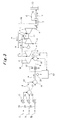
- Fig. 2 is a configuration diagram of a gas turbine device according to Embodiment 2 of the present invention. Note that, in Fig. 2 , components which are the same as those in Fig. 1 (Embodiment 1) are denoted with the same reference numerals as in Fig. 1 , and overlapping detailed description thereof will be omitted.
- a fuel gas supplier 8 of Embodiment 2 includes hydrogen/oxygen sensors 31, 39, an emergency discharge valve 32, a controller 33, and a diluent gas mixer 34 in addition to the same configuration as that of the fuel gas supplier 8 of Embodiment 1 ( Fig. 1 ).
- the hydrogen/oxygen sensor 31 is provided to the fuel supply line 9 at a position downstream of the second mixer 16, and detects the hydrogen concentration and the oxygen concentration in the mixed gas a.
- the emergency discharge valve 32 is a three-way valve provided to the fuel supply line 9 at a position downstream of the hydrogen/oxygen sensor 31.
- the emergency discharge valve 32 normally allows the mixed gas a to flow toward the gas compressor 6 so that the mixed gas a is supplied to the combustor 2.
- the emergency discharge valve 32 switches the flow direction and discharges the mixed gas a from the fuel supply line 9.
- the diluent gas mixer 34 has a configuration in which a fan 36, a gas cooler 37, and a flow regulating valve 38 are disposed in a diluent gas supply line 35 in this order from upstream.
- the upstream side of the diluent gas supply line 35 is connected to the exhaust line 12 at a position downstream of the exhaust heat recovery boiler 7, and the downstream side of the diluent gas supply line 35 is connected to the fuel supply line 9 at a position downstream of the emergency discharge valve 32.
- part of the combustion gas (exhaust gas) c flowing through the exhaust line 12 is introduced into the diluent gas supply line 35, cooled by the gas cooler 37, has its flow regulated by the flow regulating valve 38, and mixed with the mixed gas a as a diluent gas.
- the hydrogen concentration and the oxygen concentration in the mixed gas a are diluted by the part of the fuel gas a (diluent gas), and are thereby reduced.
- a mixer may be provide at the connection part to mix the mixed gas a and the combustion gas (exhaust gas) c.
- the hydrogen/oxygen sensor 39 is provided to the fuel supply line 9 at a position anywhere between a position immediately after the connection part (mixture part) which is located downstream of the emergency discharge valve 32 and at which the mixture gas a and the combustion gas (exhaust gas) c are mixed, and an entrance of the gas compressor 6.
- the hydrogen/oxygen sensor 39 detects the hydrogen concentration and the oxygen concentration in the mixed gas a or the hydrogen concentration and the oxygen concentration in a mixed gas of the mixed gas a and the combustion gas (exhaust gas) c.
- the controller 33 causes the diluent gas mixer 34 to operate when the hydrogen concentration and the oxygen concentration in the mixed gas a detected by the hydrogen/oxygen sensor 31 become equal to or more than a first set value (a value set lower than an explosion limit). In other words, the controller 33 actuates the fan 36 and opens the flow regulating valve 38 to start the flow control. As a result, the part of the combustion gas (exhaust gas) c is mixed with the mixed gas a as the diluent gas as describe above.
- a first set value a value set lower than an explosion limit
- the controller 33 causes the emergency discharge valve 32 to operate (switches the flow direction of the emergency discharge valve 32) to discharge the mixed gas a when the hydrogen concentration and the oxygen concentration in the mixed gas a detected by the hydrogen/oxygen sensor 31 become equal to or more than a second set value (a value set lower than the explosion limit) larger than the first set value.
- the controller 33 may cause the diluent gas mixer 34 to operate (actuate the fan 36 and open the flow regulating valve 38 to start the flow control) when the hydrogen concentration and the oxygen concentration in the mixed gas a detected by the hydrogen/oxygen sensor 39 become equal to or more than the first set value, and may cause the emergency discharge valve 32 to operate (switch the flow direction of the emergency discharge valve 32) to discharge the mixed gas a when the hydrogen concentration and the oxygen concentration in the mixed gas a detected by the hydrogen/oxygen sensor 39 become equal to or more than the second set value.
- the other configurations of the gas turbine device of Embodiment 2 are same as those of the gas turbine device of Embodiment 1 ( Fig. 1 ).
- the fuel gas supplier 8 is configured to include the hydrogen/oxygen sensor 31 (or 39) that detects the hydrogen concentration and the oxygen concentration in the mixed gas a, the diluent gas mixer 34 that mixes, into the mixed gas a, the diluent gas for diluting the hydrogen concentration and the oxygen concentration, and the controller 33 that causes the diluent gas mixer 34 to operate to mix the diluent gas into the mixed gas a when the hydrogen concentration and the oxygen concentration detected by the hydrogen/oxygen sensor 31 (or 39) become equal to or more than the first set value.
- the hydrogen concentration and the oxygen concentration in the mixed gas a are equal to or more than the first set value, and to dilute and reduce the hydrogen concentration and the oxygen concentration of the mixed gas a with the diluent gas before the mixed gas a with the high hydrogen concentration and oxygen concentration is supplied to the combustor 2.
- the hydrogen concentration and the oxygen concentration in the mixed gas a are suppressed to concentrations equal to or lower than the explosion limit, and the gas turbine device can be operated safely.
- the diluent gas mixer 8 is configured to mix, into the mixed gas a, the part of the combustion gas (exhaust gas) c exhausted from the gas turbine 1 as the diluent gas. Accordingly, the combustion gas is effectively used as the diluent gas, and there is no need for a nitrogen gas or the like. Thus, an efficient and inexpensive gas turbine device can be achieved.
- the fuel gas supplier 8 is configured to include the hydrogen/oxygen sensor 31 (or 39) that detects the hydrogen concentration and the oxygen concentration in the mixed gas a, the emergency discharge valve 32, and the controller 33 that causes the emergency discharge valve 32 to operate to discharge the mixed gas a when the hydrogen concentration and the oxygen concentration detected by the hydrogen/oxygen sensor 31 (or 39) become equal to or more than the second set value.
- the fuel gas supplier 8 is configured to perform the mixing of the diluent gas by the diluent gas mixer 34 and the discharge of the mixed gas a by the emergency discharge valve 32 at positions downstream of the hydrogen/oxygen sensor 31. Accordingly, the mixed gas a with high hydrogen concentration and oxygen concentration which is detected by the hydrogen/oxygen sensor 31 on an upstream side can be surely mixed with the diluent gas by the diluent gas mixer 34 and discharged by the emergency discharge valve 32 on a downstream side.
- the gas turbine device of Embodiment 2 includes the gas compressor 6 that compresses the mixed gas a and supplies the mixed gas a thus compressed to the combustor 2, and the fuel gas supplier 8 is configured to perform the mixing of the diluent gas by the diluent gas mixer 34 and the discharge of the mixed gas a by the emergency discharge valve 32 at positions upstream of the gas compressor 6. Accordingly, the mixed gas a with high hydrogen concentration and oxygen concentration is mixed with the diluent gas by the diluent gas mixer 34 and discharged by the emergency discharge valve 32 before flowing into the gas compressor 6. Thus, the risk of an explosion can be surly reduced also in the gas turbine device with the gas compressor 6.
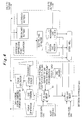
- Fig. 3 is a configuration diagram of a gas turbine device according to Embodiment 3 of the present invention. Note that, in Fig. 3 , components which are the same as those in Fig. 1 (Embodiment 1) and in Fig. 2 (Embodiment 2) are denoted with the same reference numerals as in Fig. 1 and Fig. 2 , and overlapping detailed description thereof will be omitted.
- a fuel gas supplier 8 of Embodiment 3 includes the hydrogen/oxygen sensors 31, 39, the emergency discharge valve 32, a remixer 41, and a controller 42 in addition to the same configuration as that of the fuel gas supplier 8 of Embodiment 1 ( Fig. 1 ).
- the remixer 41 is disposed on the fuel supply line 9 at a position downstream of the hydrogen/oxygen sensor 31 and the emergency discharge valve 32.
- the remixer 41 performs remixing by agitating the mixed gas a produced in the second mixer 16.
- the hydrogen/oxygen sensor 39 is provided to the fuel supply line 9 at a position anywhere between a position immediately after the remixer 41 and an entrance of the gas compressor 6, and detects the hydrogen concentration and the oxygen concentration in the mixed gas a.
- the controller 42 causes the remixer 41 to operate to remix the mixed gas a when the hydrogen concentration and the oxygen concentration in the mixed gas a detected by the hydrogen/oxygen sensor 31 become equal to or more than a first set value (a value set lower than an explosion limit).
- the controller 42 causes the emergency discharge valve 32 to operate (switches the flow direction of the emergency discharge valve 32) to discharge the mixed gas a when the hydrogen concentration and the oxygen concentration in the mixed gas a detected by the hydrogen/oxygen sensor 31 become equal to or more than a second set value (a value set lower than the explosion limit) larger than the first set value.
- the controller 42 may cause the remixer 41 to operate to remix the mixed gas a when the hydrogen concentration and the oxygen concentration in the mixed gas a detected by the hydrogen/oxygen sensor 39 become equal to or more than the first set value, and may cause the emergency discharge valve 32 to operate (switch the flow direction of the emergency discharge valve 32) to discharge the mixed gas a when the hydrogen concentration and the oxygen concentration in the mixed gas a detected by the hydrogen/oxygen sensor 39 become equal to or more than the second set value.
- the other configurations of the gas turbine device of Embodiment 3 are same as those of the gas turbine devices of Embodiment 1, 2 ( Figs. 1 , 2 ).
- the fuel gas supplier 8 has a configuration including the hydrogen/oxygen sensor 31 (or 39) that detects the hydrogen concentration and the oxygen concentration in the mixed gas a, and the controller 42 that causes the remixer 41 to operate to remix the mixed gas a when the hydrogen concentration and the oxygen concentration detected by the hydrogen/oxygen sensor 31 (or 39) become equal to or more than a first set value.
- the remixer 41 is not limited to a case where the controller 42 causes the remixer 41 to operate based on a detection signal of the hydrogen/oxygen sensor 31 (or 39) as described above. Instead, the remixer 41 may always be caused to operate continuously or intermittently.
- the fuel gas supplier 8 is configured to perform the remixing of the mixed gas a by the remixer 41 at a position downstream of the hydrogen/oxygen sensor 31. Accordingly, the mixed gas a with high hydrogen concentration and oxygen concentration which is detected by the hydrogen/oxygen sensor 31 on an upstream side can be surely remixed by the remixer 41 on a downstream side.
- the gas turbine device of Embodiment 3 includes the gas compressor 6 that compresses the mixed gas a and supplies the mixed gas a thus compressed to the combustor 2, and the fuel gas supplier 8 is configured to perform the remixing of the mixed gas a by the remixer 41 at a position upstream of the gas compressor 6. Accordingly, the mixed gas a with high hydrogen concentration and oxygen concentration is remixed by the remixer 41 before flowing into the gas compressor 6. Thus, the risk of an explosion can be surly reduced also in the gas turbine device with the gas compressor 6.
- Embodiment 3 may be combined with the configuration of Embodiment 2.
- the present invention can be applied not only to a gas turbine device dedicated to low calorie gas combustion but also to a gas turbine device which uses a mixed gas obtained by mixing together three or more types of gases as a fuel gas for a combustor.
- the present invention relates to a gas turbine device which uses a mixed gas obtained by mixing together three or more types of gases (for example, three or more types of gases from any of single gases such as a butane gas and a propane gas and gases in which multiple types of gases are mixed such as the blast furnace gas and a converter gas) as a fuel gas for a combustor, and is effective, for example, when applied to a case where a mixed gas obtained by mixing together various excessive gases produced in a steel mill is used as a fuel gas for a combustor.
- three or more types of gases for example, three or more types of gases from any of single gases such as a butane gas and a propane gas and gases in which multiple types of gases are mixed such as the blast furnace gas and a converter gas
Landscapes
- Engineering & Computer Science (AREA)
- Chemical & Material Sciences (AREA)
- Combustion & Propulsion (AREA)
- Mechanical Engineering (AREA)
- General Engineering & Computer Science (AREA)
- Engine Equipment That Uses Special Cycles (AREA)
Abstract
Description
- The present invention relates to a gas turbine device which uses a mixed gas obtained by mixing together three or more types of gases as a fuel gas for a combustor.
- A gas turbine device dedicated to low calorie gas combustion which is capable of using multiple types of low calorie gases with different calories at the same time is generally known as an example of a gas turbine device which uses a mixed gas obtained by mixing together three or more types of gases as a fuel gas for a combustor. The gas turbine device dedicated to low calorie gas combustion is used, for example, in a steel mill. In the steel mill, various excessive gases such as a blast furnace gas (B gas), a coke oven gas (C gas), and a converter gas (L gas) are produced in a manufacturing process of a steel product. These excessive gases contain combustible components. For this reason, the excessive gases are used as a fuel gas for the gas turbine device in the steel mill and the like, and thereby the excessive gases are effectively used.
- There are large variations in amount of byproduct gases produced. For this reason, when used as the fuel for the gas turbine device, any of the excessive gases is not used singly, but a mixed gas obtained by mixing multiple types of gases is used. Moreover, calorie adjustment may be performed by further mixing a natural gas (LNG) and the like into the mixed gas.
- For example, a gas turbine device disclosed in
Patent Document 1 listed below is given as a specific example of the gas turbine device which uses the mixed gas of multiple types of excessive gases and the natural gas as the fuel gas for a combustor. In the gas turbine device disclosed inPatent Document 1, as shown inFig. 4 , the blast furnace gas, the coke oven gas, and the natural gas are mixed by amixer 51, and this mixed gas is supplied to a combustor of agas turbine 52 as the fuel gas. - In addition to
Patent Document 1,Patent Document 2 is also given as a prior art document related to the present invention.Patent Document 2 discloses an example of a gas turbine device which reuses part of a combustion gas exhausted from a gas turbine by supplying the part of the combustion gas to an air compressor. - Patent Document 1: Japanese Patent Application Publication No.
2004-27975 - Patent Document 2: Japanese Patent No.
2954456 - When multiple types of gases are mixed and used as the fuel gas for a gas turbine device, if these multiple types of gases are not evenly mixed, the calorie of the mixed gas may be uneven and uneven combustion is likely to occur. Accordingly, when the multiple types of gases are mixed and used as the fuel gas for a gas turbine device, the multiple types of gases have to be mixed as evenly as possible. However, there is no particular measure related to the even mixing in the conventional gas turbine device disclosed in
Patent Document 1. - Furthermore, even if a mixed gas is produced in which multiple types of gases are evenly mixed, there is a possibility that hydrogen and oxygen in the mixed gas are released thereafter and hydrogen collection and oxygen collection are generated. When the hydrogen collection and the oxygen collection are generated, the risk of an explosion increases. Particularly, in a gas turbine device which supplies the mixed gas to a combustor after compressing the mixed gas with a gas compressor, the hydrogen collection and the oxygen collection are compressed also, and thus, the possibility of an explosion further increases.
- In view of the above circumstances, an object of the present invention is to provide a gas turbine device capable of producing a mixed gas in which three or more types of gases (for example, three or more types of gases from any of single gases such as a butane gas and a propane gas and gases in which multiple types of gases are mixed such as a blast furnace gas and a converter gas) are evenly mixed and also of preventing an explosion by monitoring a hydrogen concentration and an oxygen concentration in the mixed gas.
- A gas turbine device of a first invention for solving the above problem provides a gas turbine device configured to burn in a combustor a fuel gas supplied from a fuel gas supplier, together with a compressed air supplied from an air compressor, and to rotationally drive a gas turbine by a combustion gas generated at the burning, the gas turbine device characterized in that
the fuel gas supplier includes a plurality of mixers, and is configured to produce a mixed gas by mixing three or more types of gases in the mixers in ascending order of specific gravity or in descending order of specific gravity, and to supply the mixed gas to the combustor as the fuel gas. - A gas turbine device of a second invention provides the gas turbine device of the first invention characterized in that the fuel gas supplier is configured to include:
- a hydrogen/oxygen sensor that detects a hydrogen concentration and an oxygen concentration in the mixed gas;
- a diluent gas mixer that mixes, into the mixed gas, a diluent gas for diluting the hydrogen concentration and the oxygen concentration; and
- a controller that causes the diluent gas mixer to operate to mix the diluent gas into the mixed gas when the hydrogen concentration and the oxygen concentration detected by the hydrogen/oxygen sensor become equal to or more than a set value.
- A gas turbine device of a third invention provides the gas turbine device of the second invention characterized in that the diluent gas mixer is configured to mix, into the mixed gas, part of the combustion gas exhausted from the gas turbine as the diluent gas.
- A gas turbine device of a fourth invention provides the gas turbine device of the first invention characterized in that the fuel gas supplier is configured to include a remixer that performs remixing by agitating the mixed gas.
- A gas turbine device of a fifth invention provides the gas turbine device of the fourth invention characterized in that the fuel gas supplier is configured to include:
- a hydrogen/oxygen sensor that detects a hydrogen concentration and an oxygen concentration in the mixed gas; and
- a controller that causes the remixer to operate to remix the mixed gas when the hydrogen concentration and the oxygen concentration detected by the hydrogen/oxygen sensor become equal to or more than a set value.
- A gas turbine device of a sixth invention provides the gas turbine device of the first invention characterized in that the fuel gas supplier is configured to include:
- a hydrogen/oxygen sensor that detects a hydrogen concentration and an oxygen concentration in the mixed gas;
- an emergency discharge valve; and
- a controller that causes the emergency discharge valve to operate to discharge the mixed gas when the hydrogen concentration and the oxygen concentration detected by the hydrogen/oxygen sensor become equal to or more than a set value.
- A gas turbine device of a seventh invention provides the gas turbine device of any one of the second, fifth and sixth inventions characterized in that the fuel gas supplier is configured to perform any of the mixing of the diluent gas by the diluent gas mixer, the remixing of the mixed gas by the remixer, and the discharge of the mixed gas by the emergency discharge valve at a position downstream of the hydrogen/oxygen sensor.
- A gas turbine device of an eighth invention provides the gas turbine device of any one of the second to seventh inventions characterized by further comprising a gas compressor that compresses the mixed gas and supplies the mixed gas thus compressed to the combustor, the gas turbine device characterized in that
the fuel gas supplier is configured to perform any of the mixing of the diluent gas by the diluent gas mixer, the remixing of the mixed gas by the remixer, and the discharge of the mixed gas by the emergency discharge valve at a position upstream of the gas compressor. - The gas turbine device of the first invention provides a gas turbine device configured to burn in a combustor a fuel gas supplied from a fuel gas supplier, together with a compressed air supplied from an air compressor, and to rotationally drive a gas turbine by a combustion gas generated at the burning, the gas turbine device characterized in that the fuel gas supplier includes a plurality of mixers, and is configured to produce a mixed gas by mixing three or more types of gases in the mixers in ascending order of specific gravity or in descending order of specific gravity, and to supply the mixed gas to the combustor as the fuel gas. Accordingly, gases with similar specific gravities are mixed sequentially in both cases of mixing in ascending order of specific gravity and of mixing in descending order of specific gravity. This allows production of the mixed gas in which three or more types of gases are evenly mixed. When this evenly mixed gas is used as the fuel gas for the combustor, occurrence of uneven combustion is prevented and stable combustion is made possible.
- The gas turbine device of the second invention provides the gas turbine device of the first invention characterized in that the fuel gas supplier is configured to include: a hydrogen/oxygen sensor that detects a hydrogen concentration and an oxygen concentration in the mixed gas; a diluent gas mixer that mixes, into the mixed gas, a diluent gas for diluting the hydrogen concentration and the oxygen concentration; and a controller that causes the diluent gas mixer to operate to mix the diluent gas into the mixed gas when the hydrogen concentration and the oxygen concentration detected by the hydrogen/oxygen sensor become equal to or more than a set value. Accordingly, even when hydrogen and oxygen in the mixed gas are released and hydrogen collection and oxygen collection are generated, it is possible to detect that the hydrogen concentration and the oxygen concentration in the mixed gas are equal to or more than the set value, and to dilute and reduce the hydrogen concentration and the oxygen concentration of the mixed gas with the diluent gas before the mixed gas with the high hydrogen concentration and oxygen concentration is supplied to the combustor. Thus, the hydrogen concentration and the oxygen concentration in the mixed gas are suppressed to concentrations equal to or lower than the explosion limit, and the gas turbine device can be operated safely.
- The gas turbine device of the third invention provides the gas turbine device of the second invention characterized in that the diluent gas mixer is configured to mix, into the mixed gas, part of the combustion gas exhausted from the gas turbine as the diluent gas. Accordingly, the combustion gas is effectively used as the diluent gas, and there is no need for a nitrogen gas or the like. Thus, an efficient and inexpensive gas turbine device can be achieved.
- The gas turbine device of the fourth invention provides the gas turbine device of the first invention characterized in that the fuel gas supplier is configured to include a remixer that performs remixing by agitating the mixed gas. Accordingly, even when hydrogen and oxygen in the mixed gas are released and hydrogen collection and oxygen collection are generated (gravity separation occurs), it is possible to achieve an evenly mixed state again by performing remixing by agitating the mixed gas with the remixer before the mixed gas is supplied to the combustor. Thus, the risk of an explosion is reduced, and the gas turbine device can be operated safely.
- The gas turbine device of the fifth invention provides the gas turbine device of the fourth invention characterized in that the fuel gas supplier is configured to include: a hydrogen/oxygen sensor that detects a hydrogen concentration and an oxygen concentration in the mixed gas; and a controller that causes the remixer to operate to remix the mixed gas when the hydrogen concentration and the oxygen concentration detected by the hydrogen/oxygen sensor become equal to or more than a set value. Accordingly, even when hydrogen and oxygen in the mixed gas are released and hydrogen collection and oxygen collection are generated (gravity separation occurs), it is possible to detect that the hydrogen concentration and the oxygen concentration in the mixed gas are equal to or more than the set value before the mixed gas with the high hydrogen concentration and oxygen concentration is supplied to the combustor, and to achieve an evenly mixed state again by performing remixing by agitating the mixed gas with the remixer before the mixed gas is supplied to the combustor. Thus, the risk of an explosion is reduced, and the gas turbine device can be operated safely.
- The gas turbine device of the sixth invention provides the gas turbine device of the first invention characterized in that the fuel gas supplier is configured to include: a hydrogen/oxygen sensor that detects a hydrogen concentration and an oxygen concentration in the mixed gas; an emergency discharge valve; and a controller that causes the emergency discharge valve to operate to discharge the mixed gas when the hydrogen concentration and the oxygen concentration detected by the hydrogen/oxygen sensor become equal to or more than a set value. Accordingly, even when hydrogen and oxygen in the mixed gas a are released and hydrogen collection and oxygen collection are generated thereby causing an increase in the hydrogen concentration and the oxygen concentration of the mixed gas, it is possible to detect that the hydrogen concentration and the oxygen concentration in the mixed gas are equal to or more than the set value, and to discharge the mixed gas before the mixed gas is supplied to the combustor. Thus, the risk of an explosion is reduced, and the gas turbine device can be operated safely.
- The gas turbine device of the seventh invention provides the gas turbine device of any one of the second, fifth and sixth inventions characterized in that the fuel gas supplier is configured to perform any of the mixing of the diluent gas by the diluent gas mixer, the remixing of the mixed gas by the remixer, and the discharge of the mixed gas by the emergency discharge valve at a position downstream of the hydrogen/oxygen sensor. Accordingly, the mixed gas with high hydrogen concentration and oxygen concentration which is detected by the hydrogen/oxygen sensor on an upstream side can be surely mixed with the diluent gas by the diluent gas mixer, remixed by the remixer, or discharged by the emergency discharge valve on a downstream side.
- The gas turbine device of the eighth invention provides the gas turbine device of any one of the second to seventh inventions characterized by further comprising a gas compressor that compresses the mixed gas and supplies the mixed gas thus compressed to the combustor, the gas turbine device characterized in that the fuel gas supplier is configured to perform any of the mixing of the diluent gas by the diluent gas mixer, the remixing of the mixed gas by the remixer, and the discharge of the mixed gas by the emergency discharge valve at a position upstream of the gas compressor. Accordingly, the mixed gas with high hydrogen concentration and oxygen concentration is mixed with the diluent gas by the diluent gas mixer, remixed by the remixer, or discharged by the emergency discharge valve before flowing into the gas compressor. Thus, the risk of an explosion can be surly reduced also in the gas turbine device with the gas compressor.
-
- [
Fig. 1] Fig. 1 is a configuration diagram of a gas turbine device according toEmbodiment 1 of the present invention. - [
Fig. 2] Fig. 2 is a configuration diagram of a gas turbine device according toEmbodiment 2 of the present invention. - [
Fig. 3] Fig. 3 is a configuration diagram of a gas turbine device according toEmbodiment 3 of the present invention. - [
Fig. 4] Fig. 4 is a configuration diagram of a conventional gas turbine device. - 1 gas turbine, 2 combustor, 3 air compressor, 4 electrical generator, 5 steam turbine, 6 gas compressor, 7 exhaust heat recovery boiler, 8 fuel gas supplier, 9, 10 fuel supply line, 11 rotary shaft, 12 exhaust line, 13 stack, 14 steam line, 15 first mixer, 16 second mixer, 17 flow regulating valve, 18 fuel supply line, 19 flow regulating valve, 20, 21 fuel supply line, 22 flow regulating valve, 23 fuel supply line, 31 hydrogen/oxygen sensor, 32 emergency discharge valve, 33 controller, 34 diluent gas mixer, 35 diluent gas supply line, 36 fan, 37 gas cooler, 38 flow regulating valve, 39 hydrogen/oxygen sensor, 41 remixer, 42 controller, I first gas, II second gas, III third gas, a mixed gas (fuel gas), b compressed air, c fuel gas, exhaust gas, d feed water, e steam, f mixed gas, g outside air (air)
- Embodiments of the present invention will be described below in detail on the bases of the drawings.
-
Fig. 1 is a configuration diagram of a gas turbine device according toEmbodiment 1 of the present invention. As shown inFig. 1 , the gas turbine device ofEmbodiment 1 is a combined cycle power generating device which generates electric power by causing a gas turbine and a steam turbine to operate. The gas turbine device includes agas turbine 1, asteam turbine 5, acombustor 2, anair compressor 3, anelectrical generator 4, agas compressor 6, an exhaustheat recovery boiler 7, and afuel gas supplier 8. - A mixed gas a produced in the
fuel gas supplier 8 flows into thegas compressor 6 through afuel supply line 9, and is compressed there. Thereafter, the compressed mixed gas a is supplied to thecombustor 2 through afuel supply line 10 as a fuel gas. In thecombustor 2, the fuel gas (mixed gas a) supplied from thefuel gas supplier 8 is burned together with a compressed air b supplied from theair compressor 3. A combustion gas c produced at the burning is supplied to thegas turbine 1 to rotationally drive thegas turbine 1. - The combustion gas (exhaust gas) c exhausted from the
gas turbine 1 flows through an exhaust line (flue) 12. Then, heat is recovered from the combustion gas c via the heat exchange with a feed water d in the exhaustheat recovery boiler 7 provided to theexhaust line 12. Thereafter, the combustion gas c is dissipated from astack 13. Meanwhile, the feed water d is heated due to the heat exchange with the combustion gas (exhaust gas) c, and turns into a steam e in the exhaustheat recovery boiler 7. This steam e is supplied to thesteam turbine 5 through asteam line 14, and thus thesteam turbine 5 is rotationally driven. The steam e exhausted from thesteam turbine 5 is condensed in an unillustrated condenser, and is reused as the feed water d. - The
gas turbine 1, thesteam turbine 5, theair compressor 3, theelectrical generator 4, and thegas compressor 6 are disposed on the samerotary shaft 11. Theair compressor 3, theelectrical generator 4, and thegas compressor 6 are rotationally driven by thegas turbine 1 and thesteam turbine 5. Accordingly, theair compressor 3 takes in and compresses an outside air (air) g, and supplies this compressed air b to thecombustor 2 as described above. Theelectrical generator 4 generates electric power, and transmits this generated electric power to unillustrated power systems inside a steel mill and outside the steel mill. Thegas compressor 6 takes in and compresses the mixed gas a, and supplies this compressed mixed gas a to thecombustor 2 as described above. - The
fuel gas supplier 8, which is a characteristic feature ofEmbodiment 1, includes twomixers mixers fuel gas supplier 8 supplies this mixed gas a to thecombustor 2 through thegas compressor 6 as described above. - In detail, an inlet side of the
first mixer 15 is connected to a downstream end of afuel supply line 18 provided with aflow regulating valve 17 and also to a downstream end of afuel supply line 20 provided with aflow regulating valve 19. On the other hand, an outlet side of thefirst mixer 15 is connected to an upstream end of afuel supply line 21. Meanwhile, an inlet side of thesecond mixer 16 is connected to a downstream end of thefuel supply line 21 and also to a downstream end of afuel supply line 23 provided with aflow regulating valve 22. On the other hand, an outlet side of thesecond mixer 16 is connected to an upstream end of thefuel supply line 9. - Accordingly, in the
fuel gas supplier 8, the first gas I and the second gas II are firstly mixed in thefirst mixer 15, and a mixed gas f is produced, the first gas I supplied through thefuel supply line 18 while having its flow regulated by theflow regulating valve 17, the second gas II supplied through thefuel supply line 20 while having its flow regulated by theflow regulating valve 19. Next, the third gas III and the mixed gas f are mixed in thesecond mixer 16, and the mixed gas a is produced, the third gas III supplied through thefuel supply line 23 while having its flow regulated by theflow regulating valve 22, the mixed gas f supplied through thefuel supply line 21. - Moreover, the first gas I, the second gas II, and the third gas III are selected in a way that their relationships in terms of specific gravity satisfies the first gas I < the second gas II < the third gas III, or the first gas I > the second gas II > the third gas III. Thus, the first gas I, the second gas II, and the third gas III are mixed in ascending order of specific gravity, or in descending order of specific gravity. Table I shows specific gravities of various gases. Assume that, among these gases, a blast furnace gas, a coke oven gas, which are excessive gases generated in a steel mill, and a natural gas (LNG) are used, for example. In a case of mixing in descending order of specific gravity, the first gas I is the blast furnace gas, the second gas II is the natural gas, and the third gas III is the coke oven gas. In a case of mixing in ascending order of specific gravity, the first gas I is the coke oven gas, the second gas II is the natural gas, and the third gas III is the blast furnace gas.
-

- According to the gas turbine device of
Embodiment 1, in the gas turbine device configured to burn in thecombustor 2 the fuel gas supplied from thefuel gas supplier 8 together with the compressed air b supplied from theair compressor 3, and to rotationally drive thegas turbine 1 by the combustion gas c generated at the burning, thefuel gas supplier 8 includes the twomixers mixers combustor 2 as the fuel gas. Accordingly, gases with similar specific gravities are mixed sequentially in both cases of mixing in ascending order of specific gravity and of mixing in descending order of specific gravity. This allows production of the mixed gas a in which three types of gases of the first gas I, the second gas II, and the third gas III are evenly mixed. When this evenly mixed gas a is used as the fuel gas for thecombustor 2, occurrence of uneven combustion is prevented and stable combustion is made possible. - Note that, the present invention is not limited to a case of mixing three types of gases (for example, three types of gases from any of single gases such as a butane gas and a propane gas and gases in which multiple types of gases are mixed such as a blast furnace gas and a converter gas), and may also be applied to a case of mixing three or more types of gases (for example, three or more types of gases from any of single gases such as a butane gas and a propane gas and gases in which multiple types of gases are mixed such as a blast furnace gas and a converter gas).
-
Fig. 2 is a configuration diagram of a gas turbine device according toEmbodiment 2 of the present invention. Note that, inFig. 2 , components which are the same as those inFig. 1 (Embodiment 1) are denoted with the same reference numerals as inFig. 1 , and overlapping detailed description thereof will be omitted. - As shown in
Fig. 2 , afuel gas supplier 8 ofEmbodiment 2 includes hydrogen/oxygen sensors emergency discharge valve 32, acontroller 33, and adiluent gas mixer 34 in addition to the same configuration as that of thefuel gas supplier 8 of Embodiment 1 (Fig. 1 ). - The hydrogen/
oxygen sensor 31 is provided to thefuel supply line 9 at a position downstream of thesecond mixer 16, and detects the hydrogen concentration and the oxygen concentration in the mixed gas a. Theemergency discharge valve 32 is a three-way valve provided to thefuel supply line 9 at a position downstream of the hydrogen/oxygen sensor 31. Theemergency discharge valve 32 normally allows the mixed gas a to flow toward thegas compressor 6 so that the mixed gas a is supplied to thecombustor 2. On the other hand, in an emergency when the hydrogen concentration and the oxygen concentration in the mixed gas a are high, theemergency discharge valve 32 switches the flow direction and discharges the mixed gas a from thefuel supply line 9. - The
diluent gas mixer 34 has a configuration in which afan 36, agas cooler 37, and aflow regulating valve 38 are disposed in a diluentgas supply line 35 in this order from upstream. The upstream side of the diluentgas supply line 35 is connected to theexhaust line 12 at a position downstream of the exhaustheat recovery boiler 7, and the downstream side of the diluentgas supply line 35 is connected to thefuel supply line 9 at a position downstream of theemergency discharge valve 32. Accordingly, when thefan 36 operates, part of the combustion gas (exhaust gas) c flowing through theexhaust line 12 is introduced into the diluentgas supply line 35, cooled by thegas cooler 37, has its flow regulated by theflow regulating valve 38, and mixed with the mixed gas a as a diluent gas. At this time, the hydrogen concentration and the oxygen concentration in the mixed gas a are diluted by the part of the fuel gas a (diluent gas), and are thereby reduced. Note that, although the connection part of thefuel supply line 9 and the diluentgas supply line 35 is a mixture part in the illustrated example, a mixer may be provide at the connection part to mix the mixed gas a and the combustion gas (exhaust gas) c. The hydrogen/oxygen sensor 39 is provided to thefuel supply line 9 at a position anywhere between a position immediately after the connection part (mixture part) which is located downstream of theemergency discharge valve 32 and at which the mixture gas a and the combustion gas (exhaust gas) c are mixed, and an entrance of thegas compressor 6. The hydrogen/oxygen sensor 39 detects the hydrogen concentration and the oxygen concentration in the mixed gas a or the hydrogen concentration and the oxygen concentration in a mixed gas of the mixed gas a and the combustion gas (exhaust gas) c. - The
controller 33 causes thediluent gas mixer 34 to operate when the hydrogen concentration and the oxygen concentration in the mixed gas a detected by the hydrogen/oxygen sensor 31 become equal to or more than a first set value (a value set lower than an explosion limit). In other words, thecontroller 33 actuates thefan 36 and opens theflow regulating valve 38 to start the flow control. As a result, the part of the combustion gas (exhaust gas) c is mixed with the mixed gas a as the diluent gas as describe above. In addition, thecontroller 33 causes theemergency discharge valve 32 to operate (switches the flow direction of the emergency discharge valve 32) to discharge the mixed gas a when the hydrogen concentration and the oxygen concentration in the mixed gas a detected by the hydrogen/oxygen sensor 31 become equal to or more than a second set value (a value set lower than the explosion limit) larger than the first set value. Alternatively, thecontroller 33 may cause thediluent gas mixer 34 to operate (actuate thefan 36 and open theflow regulating valve 38 to start the flow control) when the hydrogen concentration and the oxygen concentration in the mixed gas a detected by the hydrogen/oxygen sensor 39 become equal to or more than the first set value, and may cause theemergency discharge valve 32 to operate (switch the flow direction of the emergency discharge valve 32) to discharge the mixed gas a when the hydrogen concentration and the oxygen concentration in the mixed gas a detected by the hydrogen/oxygen sensor 39 become equal to or more than the second set value. - The other configurations of the gas turbine device of
Embodiment 2 are same as those of the gas turbine device of Embodiment 1 (Fig. 1 ). - According to the gas turbine device of
Embodiment 2, operational effects similar to those of the above-describedEmbodiment 1 can be obtained. In addition to that, the following effect is obtained. Thefuel gas supplier 8 is configured to include the hydrogen/oxygen sensor 31 (or 39) that detects the hydrogen concentration and the oxygen concentration in the mixed gas a, thediluent gas mixer 34 that mixes, into the mixed gas a, the diluent gas for diluting the hydrogen concentration and the oxygen concentration, and thecontroller 33 that causes thediluent gas mixer 34 to operate to mix the diluent gas into the mixed gas a when the hydrogen concentration and the oxygen concentration detected by the hydrogen/oxygen sensor 31 (or 39) become equal to or more than the first set value. Accordingly, even when hydrogen and oxygen in the mixed gas a are released and hydrogen collection and oxygen collection are generated, it is possible to detect that the hydrogen concentration and the oxygen concentration in the mixed gas a are equal to or more than the first set value, and to dilute and reduce the hydrogen concentration and the oxygen concentration of the mixed gas a with the diluent gas before the mixed gas a with the high hydrogen concentration and oxygen concentration is supplied to thecombustor 2. Thus, the hydrogen concentration and the oxygen concentration in the mixed gas a are suppressed to concentrations equal to or lower than the explosion limit, and the gas turbine device can be operated safely. - Moreover, according to the gas turbine device of
Embodiment 2, thediluent gas mixer 8 is configured to mix, into the mixed gas a, the part of the combustion gas (exhaust gas) c exhausted from thegas turbine 1 as the diluent gas. Accordingly, the combustion gas is effectively used as the diluent gas, and there is no need for a nitrogen gas or the like. Thus, an efficient and inexpensive gas turbine device can be achieved. - Additionally, according to the gas turbine device of
Embodiment 2, thefuel gas supplier 8 is configured to include the hydrogen/oxygen sensor 31 (or 39) that detects the hydrogen concentration and the oxygen concentration in the mixed gas a, theemergency discharge valve 32, and thecontroller 33 that causes theemergency discharge valve 32 to operate to discharge the mixed gas a when the hydrogen concentration and the oxygen concentration detected by the hydrogen/oxygen sensor 31 (or 39) become equal to or more than the second set value. Accordingly, even when hydrogen and oxygen in the mixed gas a are released and hydrogen collection and oxygen collection are generated thereby causing an increase in the hydrogen concentration and the oxygen concentration of the mixed gas a, it is possible to detect that the hydrogen concentration and the oxygen concentration in the mixed gas are equal to or more than the second set value, and to discharge the mixed gas a before the mixed gas a is supplied to thecombustor 2. Thus, the risk of an explosion is reduced, and the gas turbine device can be operated safely. - Further, according to the gas turbine device of
Embodiment 2, thefuel gas supplier 8 is configured to perform the mixing of the diluent gas by thediluent gas mixer 34 and the discharge of the mixed gas a by theemergency discharge valve 32 at positions downstream of the hydrogen/oxygen sensor 31. Accordingly, the mixed gas a with high hydrogen concentration and oxygen concentration which is detected by the hydrogen/oxygen sensor 31 on an upstream side can be surely mixed with the diluent gas by thediluent gas mixer 34 and discharged by theemergency discharge valve 32 on a downstream side. - Moreover, the gas turbine device of
Embodiment 2 includes thegas compressor 6 that compresses the mixed gas a and supplies the mixed gas a thus compressed to thecombustor 2, and thefuel gas supplier 8 is configured to perform the mixing of the diluent gas by thediluent gas mixer 34 and the discharge of the mixed gas a by theemergency discharge valve 32 at positions upstream of thegas compressor 6. Accordingly, the mixed gas a with high hydrogen concentration and oxygen concentration is mixed with the diluent gas by thediluent gas mixer 34 and discharged by theemergency discharge valve 32 before flowing into thegas compressor 6. Thus, the risk of an explosion can be surly reduced also in the gas turbine device with thegas compressor 6. -
Fig. 3 is a configuration diagram of a gas turbine device according toEmbodiment 3 of the present invention. Note that, inFig. 3 , components which are the same as those inFig. 1 (Embodiment 1) and inFig. 2 (Embodiment 2) are denoted with the same reference numerals as inFig. 1 andFig. 2 , and overlapping detailed description thereof will be omitted. - As shown in
Fig. 3 , afuel gas supplier 8 ofEmbodiment 3 includes the hydrogen/oxygen sensors emergency discharge valve 32, aremixer 41, and acontroller 42 in addition to the same configuration as that of thefuel gas supplier 8 of Embodiment 1 (Fig. 1 ). - The
remixer 41 is disposed on thefuel supply line 9 at a position downstream of the hydrogen/oxygen sensor 31 and theemergency discharge valve 32. Theremixer 41 performs remixing by agitating the mixed gas a produced in thesecond mixer 16. The hydrogen/oxygen sensor 39 is provided to thefuel supply line 9 at a position anywhere between a position immediately after theremixer 41 and an entrance of thegas compressor 6, and detects the hydrogen concentration and the oxygen concentration in the mixed gas a. Thecontroller 42 causes theremixer 41 to operate to remix the mixed gas a when the hydrogen concentration and the oxygen concentration in the mixed gas a detected by the hydrogen/oxygen sensor 31 become equal to or more than a first set value (a value set lower than an explosion limit). In addition, thecontroller 42 causes theemergency discharge valve 32 to operate (switches the flow direction of the emergency discharge valve 32) to discharge the mixed gas a when the hydrogen concentration and the oxygen concentration in the mixed gas a detected by the hydrogen/oxygen sensor 31 become equal to or more than a second set value (a value set lower than the explosion limit) larger than the first set value. Alternatively, thecontroller 42 may cause theremixer 41 to operate to remix the mixed gas a when the hydrogen concentration and the oxygen concentration in the mixed gas a detected by the hydrogen/oxygen sensor 39 become equal to or more than the first set value, and may cause theemergency discharge valve 32 to operate (switch the flow direction of the emergency discharge valve 32) to discharge the mixed gas a when the hydrogen concentration and the oxygen concentration in the mixed gas a detected by the hydrogen/oxygen sensor 39 become equal to or more than the second set value. - The other configurations of the gas turbine device of
Embodiment 3 are same as those of the gas turbine devices ofEmbodiment 1, 2 (Figs. 1 ,2 ). - According to the gas turbine device of
Embodiment 3, operational effects similar to those of the above-describedEmbodiment 1 can be obtained, and operational effects of theemergency valve 32 similar to those of the above-describedEmbodiment 2 can be obtained. In addition to that, following effect is obtained. Thefuel gas supplier 8 has a configuration including the hydrogen/oxygen sensor 31 (or 39) that detects the hydrogen concentration and the oxygen concentration in the mixed gas a, and thecontroller 42 that causes theremixer 41 to operate to remix the mixed gas a when the hydrogen concentration and the oxygen concentration detected by the hydrogen/oxygen sensor 31 (or 39) become equal to or more than a first set value. Accordingly, even when hydrogen and oxygen in the mixed gas a are released and hydrogen collection and oxygen collection are generated (gravity separation occurs), it is possible to detect that the hydrogen concentration and the oxygen concentration in the mixed gas a are equal to or more than the first set value before the mixed gas a with the high hydrogen concentration and oxygen concentration is supplied to thecombustor 2, and to achieve an evenly mixed state again by performing remixing by agitating the mixed gas a with theremixer 2 before the mixed gas a is supplied to thecombustor 2. Thus, the risk of an explosion is reduced, and the gas turbine device can be operated safely. - Note that, the
remixer 41 is not limited to a case where thecontroller 42 causes theremixer 41 to operate based on a detection signal of the hydrogen/oxygen sensor 31 (or 39) as described above. Instead, theremixer 41 may always be caused to operate continuously or intermittently. - Further, according to the gas turbine device of
Embodiment 3, thefuel gas supplier 8 is configured to perform the remixing of the mixed gas a by theremixer 41 at a position downstream of the hydrogen/oxygen sensor 31. Accordingly, the mixed gas a with high hydrogen concentration and oxygen concentration which is detected by the hydrogen/oxygen sensor 31 on an upstream side can be surely remixed by theremixer 41 on a downstream side. - Moreover, the gas turbine device of
Embodiment 3 includes thegas compressor 6 that compresses the mixed gas a and supplies the mixed gas a thus compressed to thecombustor 2, and thefuel gas supplier 8 is configured to perform the remixing of the mixed gas a by theremixer 41 at a position upstream of thegas compressor 6. Accordingly, the mixed gas a with high hydrogen concentration and oxygen concentration is remixed by theremixer 41 before flowing into thegas compressor 6. Thus, the risk of an explosion can be surly reduced also in the gas turbine device with thegas compressor 6. - Note that, the configuration of
Embodiment 3 may be combined with the configuration ofEmbodiment 2. - Moreover, the present invention can be applied not only to a gas turbine device dedicated to low calorie gas combustion but also to a gas turbine device which uses a mixed gas obtained by mixing together three or more types of gases as a fuel gas for a combustor.
- The present invention relates to a gas turbine device which uses a mixed gas obtained by mixing together three or more types of gases (for example, three or more types of gases from any of single gases such as a butane gas and a propane gas and gases in which multiple types of gases are mixed such as the blast furnace gas and a converter gas) as a fuel gas for a combustor, and is effective, for example, when applied to a case where a mixed gas obtained by mixing together various excessive gases produced in a steel mill is used as a fuel gas for a combustor.
Claims (8)
- A gas turbine device configured to burn in a combustor a fuel gas supplied from a fuel gas supplier, together with a compressed air supplied from an air compressor, and to rotationally drive a gas turbine by a combustion gas generated at the burning, the gas turbine device characterized in that
the fuel gas supplier includes a plurality of mixers, and is configured to produce a mixed gas by mixing three or more types of gases in the mixers in ascending order of specific gravity or in descending order of specific gravity, and to supply the mixed gas to the combustor as the fuel gas. - The gas turbine device according to claim 1, characterized in that the fuel gas supplier is configured to include:a hydrogen/oxygen sensor that detects a hydrogen concentration and an oxygen concentration in the mixed gas;a diluent gas mixer that mixes, into the mixed gas, a diluent gas for diluting the hydrogen concentration and the oxygen concentration; anda controller that causes the diluent gas mixer to operate to mix the diluent gas into the mixed gas when the hydrogen concentration and the oxygen concentration detected by the hydrogen/oxygen sensor become equal to or more than a set value.
- The gas turbine device according to claim 2, characterized in that the diluent gas mixer is configured to mix, into the mixed gas, part of the combustion gas exhausted from the gas turbine as the diluent gas.
- The gas turbine device according to claim 1, characterized in that the fuel gas supplier is configured to include a remixer that performs remixing by agitating the mixed gas.
- The gas turbine device according to claim 4, characterized in that the fuel gas supplier is configured to include:a hydrogen/oxygen sensor that detects a hydrogen concentration and an oxygen concentration in the mixed gas; anda controller that causes the remixer to operate to remix the mixed gas when the hydrogen concentration and the oxygen concentration detected by the hydrogen/oxygen sensor become equal to or more than a set value.
- The gas turbine device according to claim 1, characterized in that the fuel gas supplier is configured to include:a hydrogen/oxygen sensor that detects a hydrogen concentration and an oxygen concentration in the mixed gas;an emergency discharge valve; anda controller that causes the emergency discharge valve to operate to discharge the mixed gas when the hydrogen concentration and the oxygen concentration detected by the hydrogen/oxygen sensor become equal to or more than a set value.
- The gas turbine device according to any one of claims 2, 5, and 6, characterized in that the fuel gas supplier is configured to perform any of the mixing of the diluent gas by the diluent gas mixer, the remixing of the mixed gas by the remixer, and the discharge of the mixed gas by the emergency discharge valve at a position downstream of the hydrogen/oxygen sensor.
- The gas turbine device according to any one of claims 2 to 7, characterized by further comprising a gas compressor that compresses the mixed gas and supplies the mixed gas thus compressed to the combustor, the gas turbine device characterized in that
the fuel gas supplier is configured to perform any of the mixing of the diluent gas by the diluent gas mixer, the remixing of the mixed gas by the remixer, and the discharge of the mixed gas by the emergency discharge valve at a position upstream of the gas compressor.
Applications Claiming Priority (1)
| Application Number | Priority Date | Filing Date | Title |
|---|---|---|---|
| PCT/JP2008/067825 WO2010038290A1 (en) | 2008-10-01 | 2008-10-01 | Gas turbine device |
Publications (3)
| Publication Number | Publication Date |
|---|---|
| EP2330281A1 true EP2330281A1 (en) | 2011-06-08 |
| EP2330281A4 EP2330281A4 (en) | 2014-11-05 |
| EP2330281B1 EP2330281B1 (en) | 2015-12-23 |
Family
ID=42073083
Family Applications (1)
| Application Number | Title | Priority Date | Filing Date |
|---|---|---|---|
| EP08877149.8A Active EP2330281B1 (en) | 2008-10-01 | 2008-10-01 | Gas turbine device |
Country Status (5)
| Country | Link |
|---|---|
| US (1) | US9097188B2 (en) |
| EP (1) | EP2330281B1 (en) |
| KR (3) | KR101369116B1 (en) |
| CN (1) | CN102076941B (en) |
| WO (1) | WO2010038290A1 (en) |
Families Citing this family (13)
| Publication number | Priority date | Publication date | Assignee | Title |
|---|---|---|---|---|
| DE102009031436A1 (en) * | 2009-07-01 | 2011-01-05 | Uhde Gmbh | Method and device for keeping warm coke oven chambers during standstill of a waste heat boiler |
| CA2801476C (en) * | 2010-07-02 | 2017-08-15 | Exxonmobil Upstream Research Company | Low emission triple-cycle power generation systems and methods |
| WO2013058209A1 (en) * | 2011-10-17 | 2013-04-25 | 川崎重工業株式会社 | Lean fuel intake gas turbine |
| US9778776B2 (en) | 2012-07-30 | 2017-10-03 | Beijing Lenovo Software Ltd. | Method and system for processing data |
| JP6099408B2 (en) * | 2013-01-18 | 2017-03-22 | 三菱日立パワーシステムズ株式会社 | Power generation system and method for operating power generation system |
| JP6134587B2 (en) * | 2013-06-11 | 2017-05-24 | ヤンマー株式会社 | Gas engine |
| US20150082800A1 (en) * | 2013-09-25 | 2015-03-26 | Korea Electric Power Corporation | Method for suppressing generation of yellow plum of complex thermal power plant using high thermal capacity gas |
| PL3269948T3 (en) * | 2016-07-15 | 2022-07-18 | Carbon-Clean Technologies Gmbh | Method for the adaptation of the performance of a steam turbine power plant installation and steam turbine power plant installation |
| NL2021484B1 (en) * | 2018-08-20 | 2020-04-23 | Micro Turbine Tech B V | Fuel / air supply device |
| EP3862549B1 (en) * | 2020-02-05 | 2025-05-07 | General Electric Technology GmbH | Method for operating a power plant, and power plant |
| KR102773279B1 (en) * | 2022-07-11 | 2025-02-27 | 에이치디한국조선해양 주식회사 | Apparatus for controlling fuel supply of ship |
| US20250172287A1 (en) * | 2023-11-28 | 2025-05-29 | Microchip Technology Incorporated | Controlling an air flow rate provided to a burner based on a concentration of gas provided to the burner |
| US12378922B1 (en) | 2024-05-08 | 2025-08-05 | Pwrtek, Llc | Blending gaseous fuels for energy conversion systems |
Family Cites Families (25)
| Publication number | Priority date | Publication date | Assignee | Title |
|---|---|---|---|---|
| US4761948A (en) | 1987-04-09 | 1988-08-09 | Solar Turbines Incorporated | Wide range gaseous fuel combustion system for gas turbine engines |
| JPH0439392Y2 (en) * | 1987-12-18 | 1992-09-16 | ||
| JPH01286260A (en) | 1988-05-13 | 1989-11-17 | Fuji Electric Co Ltd | Protecting device for fuel cell |
| JPH083770Y2 (en) | 1989-08-04 | 1996-01-31 | 株式会社鶴見製作所 | Structure of fixed part of fixed seal ring in mechanical seal |
| JPH05125958A (en) | 1991-11-01 | 1993-05-21 | Mitsubishi Heavy Ind Ltd | Liquid fuel supply device |
| JPH05138308A (en) | 1991-11-15 | 1993-06-01 | Kawasaki Steel Corp | Method and device for improving surface characteristic of metal cast strip |
| JP2954456B2 (en) | 1993-07-14 | 1999-09-27 | 株式会社日立製作所 | Exhaust recirculation combined plant |
| JP2001107743A (en) * | 1999-10-05 | 2001-04-17 | Mitsubishi Heavy Ind Ltd | Gas turbine system and combined plant having the same |
| US6397575B2 (en) * | 2000-03-23 | 2002-06-04 | General Electric Company | Apparatus and methods of reheating gas turbine cooling steam and high pressure steam turbine exhaust in a combined cycle power generating system |
| JP2003254090A (en) | 2002-02-26 | 2003-09-10 | Jfe Steel Kk | Apparatus and method for mixing blast furnace gas and additive gas |
| JP4003553B2 (en) | 2002-06-26 | 2007-11-07 | Jfeスチール株式会社 | Power generation method and power generation facility using by-product gas |
| KR100785955B1 (en) * | 2002-10-10 | 2007-12-14 | 엘피피 컴버션, 엘엘씨 | System for vaporization of liquid fuels for combustion and method of use |
| JP2004332057A (en) | 2003-05-08 | 2004-11-25 | Sumitomo Metal Ind Ltd | Abnormality detection method of gas measurement device in converter or vacuum decarburization furnace |
| US7007487B2 (en) * | 2003-07-31 | 2006-03-07 | Mes International, Inc. | Recuperated gas turbine engine system and method employing catalytic combustion |
| JP4011572B2 (en) | 2004-09-10 | 2007-11-21 | カワサキプラントシステムズ株式会社 | Gas reforming equipment |
| CN101023255B (en) | 2004-09-29 | 2010-05-05 | 川崎重工业株式会社 | Gas turbine plant, low-calorie gas supply plant, and method for suppressing increase in calorie of gas |
| EP1645804A1 (en) * | 2004-10-11 | 2006-04-12 | Siemens Aktiengesellschaft | Method for operating a burner, especially a gas turbine burner, and apparatus for executing the method |
| CN100575789C (en) | 2005-02-18 | 2009-12-30 | 川崎重工业株式会社 | Gas calorific value control method and gas calorific value control device |
| JP2006233920A (en) | 2005-02-28 | 2006-09-07 | Mitsubishi Heavy Ind Ltd | System for controlling calorific value of fuel gas and gas-turbine system |
| JP4563242B2 (en) | 2005-04-19 | 2010-10-13 | 三菱重工業株式会社 | Fuel gas calorie control method and apparatus |
| JP4728176B2 (en) * | 2005-06-24 | 2011-07-20 | 株式会社日立製作所 | Burner, gas turbine combustor and burner cooling method |
| JP4642630B2 (en) * | 2005-10-20 | 2011-03-02 | カワサキプラントシステムズ株式会社 | Gas turbine control system and control method |
| JP2007113541A (en) | 2005-10-24 | 2007-05-10 | Kawasaki Plant Systems Ltd | Heat reducing facility and heat reducing method for gas turbine fuel gas |
| JP4744349B2 (en) | 2006-04-24 | 2011-08-10 | 中国電力株式会社 | Gas replacement method, gas replacement device, and fuel gas replacement gas |
| US7950216B2 (en) | 2007-01-30 | 2011-05-31 | Pratt & Whitney Canada Corp. | Gas turbine engine fuel control system |
-
2008
- 2008-10-01 KR KR1020137014304A patent/KR101369116B1/en active Active
- 2008-10-01 EP EP08877149.8A patent/EP2330281B1/en active Active
- 2008-10-01 WO PCT/JP2008/067825 patent/WO2010038290A1/en not_active Ceased
- 2008-10-01 KR KR1020137014303A patent/KR101369102B1/en active Active
- 2008-10-01 KR KR1020107028985A patent/KR101324900B1/en active Active
- 2008-10-01 CN CN2008801300542A patent/CN102076941B/en active Active
- 2008-10-01 US US12/999,374 patent/US9097188B2/en active Active
Also Published As
| Publication number | Publication date |
|---|---|
| WO2010038290A1 (en) | 2010-04-08 |
| KR20130065740A (en) | 2013-06-19 |
| KR101369116B1 (en) | 2014-03-04 |
| EP2330281A4 (en) | 2014-11-05 |
| US9097188B2 (en) | 2015-08-04 |
| KR101369102B1 (en) | 2014-02-28 |
| KR101324900B1 (en) | 2013-11-04 |
| KR20130065739A (en) | 2013-06-19 |
| EP2330281B1 (en) | 2015-12-23 |
| CN102076941B (en) | 2013-11-06 |
| US20110167783A1 (en) | 2011-07-14 |
| CN102076941A (en) | 2011-05-25 |
| KR20110028462A (en) | 2011-03-18 |
Similar Documents
| Publication | Publication Date | Title |
|---|---|---|
| EP2330281B1 (en) | Gas turbine device | |
| EP2141335B1 (en) | An inlet air heating system for a gas turbine engine | |
| JP2012145111A5 (en) | ||
| US11300047B2 (en) | Combustion device and gas turbine | |
| JP5674281B2 (en) | Dry three-way catalytic reduction method for gas turbine NOx | |
| EP2182279B1 (en) | Oxyfuel boiler system and method of controlling the same | |
| US9500127B2 (en) | Power plant and method for its operation | |
| US8899011B2 (en) | Method and device for generating electricity and gypsum from waste gases containing hydrogen sulfide | |
| JP2000500837A (en) | Method and apparatus for crushing volatile organic compounds | |
| CN103089453A (en) | Apparatus for head end direct air injection with enhanced mixing capabilities | |
| JP4898594B2 (en) | Gas turbine equipment | |
| JP2007500815A (en) | Recovered heat exchange gas turbine engine system and method employing catalytic combustion | |
| US10196976B2 (en) | System and method for producing hydrogen rich fuel | |
| EP2578840A2 (en) | Power plant with exhaust gas recirculation system | |
| JP5200150B2 (en) | Gas turbine equipment | |
| JP5124041B2 (en) | Gas turbine equipment | |
| US11421163B2 (en) | Device and method for desulfurizing crude oil | |
| JPH0671138A (en) | Denitrification control apparatus | |
| KR960012351B1 (en) | Gas turbine system | |
| HK1195357B (en) | Method and device for generating electricity and gypsum from waste gases containing hydrogen sulfide | |
| TW201432136A (en) | System and method for diffusion combustion with fuel-diluent mixing in a stoichiometric exhaust gas recirculation gas turbine system |
Legal Events
| Date | Code | Title | Description |
|---|---|---|---|
| PUAI | Public reference made under article 153(3) epc to a published international application that has entered the european phase |
Free format text: ORIGINAL CODE: 0009012 |
|
| 17P | Request for examination filed |
Effective date: 20101202 |
|
| AK | Designated contracting states |
Kind code of ref document: A1 Designated state(s): AT BE BG CH CY CZ DE DK EE ES FI FR GB GR HR HU IE IS IT LI LT LU LV MC MT NL NO PL PT RO SE SI SK TR |
|
| AX | Request for extension of the european patent |
Extension state: AL BA MK RS |
|
| DAX | Request for extension of the european patent (deleted) | ||
| A4 | Supplementary search report drawn up and despatched |
Effective date: 20141002 |
|
| RIC1 | Information provided on ipc code assigned before grant |
Ipc: F02C 7/22 20060101AFI20140926BHEP Ipc: F02C 3/30 20060101ALI20140926BHEP Ipc: F02C 9/40 20060101ALI20140926BHEP Ipc: F02C 6/00 20060101ALI20140926BHEP |
|
| RAP1 | Party data changed (applicant data changed or rights of an application transferred) |
Owner name: MITSUBISHI HITACHI POWER SYSTEMS, LTD. |
|
| RAP1 | Party data changed (applicant data changed or rights of an application transferred) |
Owner name: MITSUBISHI HITACHI POWER SYSTEMS, LTD. |
|
| GRAP | Despatch of communication of intention to grant a patent |
Free format text: ORIGINAL CODE: EPIDOSNIGR1 |
|
| INTG | Intention to grant announced |
Effective date: 20150605 |
|
| GRAS | Grant fee paid |
Free format text: ORIGINAL CODE: EPIDOSNIGR3 |
|
| GRAA | (expected) grant |
Free format text: ORIGINAL CODE: 0009210 |
|
| AK | Designated contracting states |
Kind code of ref document: B1 Designated state(s): AT BE BG CH CY CZ DE DK EE ES FI FR GB GR HR HU IE IS IT LI LT LU LV MC MT NL NO PL PT RO SE SI SK TR |
|
| REG | Reference to a national code |
Ref country code: GB Ref legal event code: FG4D |
|
| REG | Reference to a national code |
Ref country code: CH Ref legal event code: EP |
|
| REG | Reference to a national code |
Ref country code: IE Ref legal event code: FG4D |
|
| REG | Reference to a national code |
Ref country code: AT Ref legal event code: REF Ref document number: 766681 Country of ref document: AT Kind code of ref document: T Effective date: 20160115 |
|
| REG | Reference to a national code |
Ref country code: DE Ref legal event code: R096 Ref document number: 602008041723 Country of ref document: DE |
|
| REG | Reference to a national code |
Ref country code: LT Ref legal event code: MG4D |
|
| REG | Reference to a national code |
Ref country code: NL Ref legal event code: MP Effective date: 20151223 |
|
| PG25 | Lapsed in a contracting state [announced via postgrant information from national office to epo] |
Ref country code: HR Free format text: LAPSE BECAUSE OF FAILURE TO SUBMIT A TRANSLATION OF THE DESCRIPTION OR TO PAY THE FEE WITHIN THE PRESCRIBED TIME-LIMIT Effective date: 20151223 Ref country code: NO Free format text: LAPSE BECAUSE OF FAILURE TO SUBMIT A TRANSLATION OF THE DESCRIPTION OR TO PAY THE FEE WITHIN THE PRESCRIBED TIME-LIMIT Effective date: 20160323 Ref country code: LT Free format text: LAPSE BECAUSE OF FAILURE TO SUBMIT A TRANSLATION OF THE DESCRIPTION OR TO PAY THE FEE WITHIN THE PRESCRIBED TIME-LIMIT Effective date: 20151223 |
|
| REG | Reference to a national code |
Ref country code: AT Ref legal event code: MK05 Ref document number: 766681 Country of ref document: AT Kind code of ref document: T Effective date: 20151223 |
|
| PG25 | Lapsed in a contracting state [announced via postgrant information from national office to epo] |
Ref country code: FI Free format text: LAPSE BECAUSE OF FAILURE TO SUBMIT A TRANSLATION OF THE DESCRIPTION OR TO PAY THE FEE WITHIN THE PRESCRIBED TIME-LIMIT Effective date: 20151223 Ref country code: GR Free format text: LAPSE BECAUSE OF FAILURE TO SUBMIT A TRANSLATION OF THE DESCRIPTION OR TO PAY THE FEE WITHIN THE PRESCRIBED TIME-LIMIT Effective date: 20160324 Ref country code: SE Free format text: LAPSE BECAUSE OF FAILURE TO SUBMIT A TRANSLATION OF THE DESCRIPTION OR TO PAY THE FEE WITHIN THE PRESCRIBED TIME-LIMIT Effective date: 20151223 Ref country code: NL Free format text: LAPSE BECAUSE OF FAILURE TO SUBMIT A TRANSLATION OF THE DESCRIPTION OR TO PAY THE FEE WITHIN THE PRESCRIBED TIME-LIMIT Effective date: 20151223 Ref country code: LV Free format text: LAPSE BECAUSE OF FAILURE TO SUBMIT A TRANSLATION OF THE DESCRIPTION OR TO PAY THE FEE WITHIN THE PRESCRIBED TIME-LIMIT Effective date: 20151223 |
|
| PG25 | Lapsed in a contracting state [announced via postgrant information from national office to epo] |
Ref country code: IT Free format text: LAPSE BECAUSE OF FAILURE TO SUBMIT A TRANSLATION OF THE DESCRIPTION OR TO PAY THE FEE WITHIN THE PRESCRIBED TIME-LIMIT Effective date: 20151223 Ref country code: ES Free format text: LAPSE BECAUSE OF FAILURE TO SUBMIT A TRANSLATION OF THE DESCRIPTION OR TO PAY THE FEE WITHIN THE PRESCRIBED TIME-LIMIT Effective date: 20151223 Ref country code: CZ Free format text: LAPSE BECAUSE OF FAILURE TO SUBMIT A TRANSLATION OF THE DESCRIPTION OR TO PAY THE FEE WITHIN THE PRESCRIBED TIME-LIMIT Effective date: 20151223 |
|
| PG25 | Lapsed in a contracting state [announced via postgrant information from national office to epo] |
Ref country code: IS Free format text: LAPSE BECAUSE OF FAILURE TO SUBMIT A TRANSLATION OF THE DESCRIPTION OR TO PAY THE FEE WITHIN THE PRESCRIBED TIME-LIMIT Effective date: 20160423 Ref country code: RO Free format text: LAPSE BECAUSE OF FAILURE TO SUBMIT A TRANSLATION OF THE DESCRIPTION OR TO PAY THE FEE WITHIN THE PRESCRIBED TIME-LIMIT Effective date: 20151223 Ref country code: PT Free format text: LAPSE BECAUSE OF FAILURE TO SUBMIT A TRANSLATION OF THE DESCRIPTION OR TO PAY THE FEE WITHIN THE PRESCRIBED TIME-LIMIT Effective date: 20160426 Ref country code: AT Free format text: LAPSE BECAUSE OF FAILURE TO SUBMIT A TRANSLATION OF THE DESCRIPTION OR TO PAY THE FEE WITHIN THE PRESCRIBED TIME-LIMIT Effective date: 20151223 Ref country code: PL Free format text: LAPSE BECAUSE OF FAILURE TO SUBMIT A TRANSLATION OF THE DESCRIPTION OR TO PAY THE FEE WITHIN THE PRESCRIBED TIME-LIMIT Effective date: 20151223 Ref country code: EE Free format text: LAPSE BECAUSE OF FAILURE TO SUBMIT A TRANSLATION OF THE DESCRIPTION OR TO PAY THE FEE WITHIN THE PRESCRIBED TIME-LIMIT Effective date: 20151223 Ref country code: SK Free format text: LAPSE BECAUSE OF FAILURE TO SUBMIT A TRANSLATION OF THE DESCRIPTION OR TO PAY THE FEE WITHIN THE PRESCRIBED TIME-LIMIT Effective date: 20151223 |
|
| REG | Reference to a national code |
Ref country code: DE Ref legal event code: R097 Ref document number: 602008041723 Country of ref document: DE |
|
| PLBE | No opposition filed within time limit |
Free format text: ORIGINAL CODE: 0009261 |
|
| STAA | Information on the status of an ep patent application or granted ep patent |
Free format text: STATUS: NO OPPOSITION FILED WITHIN TIME LIMIT |
|
| PG25 | Lapsed in a contracting state [announced via postgrant information from national office to epo] |
Ref country code: DK Free format text: LAPSE BECAUSE OF FAILURE TO SUBMIT A TRANSLATION OF THE DESCRIPTION OR TO PAY THE FEE WITHIN THE PRESCRIBED TIME-LIMIT Effective date: 20151223 |
|
| 26N | No opposition filed |
Effective date: 20160926 |
|
| PG25 | Lapsed in a contracting state [announced via postgrant information from national office to epo] |
Ref country code: BE Free format text: LAPSE BECAUSE OF FAILURE TO SUBMIT A TRANSLATION OF THE DESCRIPTION OR TO PAY THE FEE WITHIN THE PRESCRIBED TIME-LIMIT Effective date: 20151223 |
|
| PG25 | Lapsed in a contracting state [announced via postgrant information from national office to epo] |
Ref country code: SI Free format text: LAPSE BECAUSE OF FAILURE TO SUBMIT A TRANSLATION OF THE DESCRIPTION OR TO PAY THE FEE WITHIN THE PRESCRIBED TIME-LIMIT Effective date: 20151223 |
|
| REG | Reference to a national code |
Ref country code: CH Ref legal event code: PL |
|
| GBPC | Gb: european patent ceased through non-payment of renewal fee |
Effective date: 20161001 |
|
| REG | Reference to a national code |
Ref country code: IE Ref legal event code: MM4A |
|
| REG | Reference to a national code |
Ref country code: FR Ref legal event code: ST Effective date: 20170630 |
|
| PG25 | Lapsed in a contracting state [announced via postgrant information from national office to epo] |
Ref country code: CH Free format text: LAPSE BECAUSE OF NON-PAYMENT OF DUE FEES Effective date: 20161031 Ref country code: LI Free format text: LAPSE BECAUSE OF NON-PAYMENT OF DUE FEES Effective date: 20161031 Ref country code: FR Free format text: LAPSE BECAUSE OF NON-PAYMENT OF DUE FEES Effective date: 20161102 Ref country code: GB Free format text: LAPSE BECAUSE OF NON-PAYMENT OF DUE FEES Effective date: 20161001 |
|
| PG25 | Lapsed in a contracting state [announced via postgrant information from national office to epo] |
Ref country code: LU Free format text: LAPSE BECAUSE OF NON-PAYMENT OF DUE FEES Effective date: 20161001 |
|
| PG25 | Lapsed in a contracting state [announced via postgrant information from national office to epo] |
Ref country code: IE Free format text: LAPSE BECAUSE OF NON-PAYMENT OF DUE FEES Effective date: 20161001 |
|
| PG25 | Lapsed in a contracting state [announced via postgrant information from national office to epo] |
Ref country code: HU Free format text: LAPSE BECAUSE OF FAILURE TO SUBMIT A TRANSLATION OF THE DESCRIPTION OR TO PAY THE FEE WITHIN THE PRESCRIBED TIME-LIMIT; INVALID AB INITIO Effective date: 20081001 Ref country code: CY Free format text: LAPSE BECAUSE OF FAILURE TO SUBMIT A TRANSLATION OF THE DESCRIPTION OR TO PAY THE FEE WITHIN THE PRESCRIBED TIME-LIMIT Effective date: 20151223 |
|
| PG25 | Lapsed in a contracting state [announced via postgrant information from national office to epo] |
Ref country code: MC Free format text: LAPSE BECAUSE OF FAILURE TO SUBMIT A TRANSLATION OF THE DESCRIPTION OR TO PAY THE FEE WITHIN THE PRESCRIBED TIME-LIMIT Effective date: 20151223 Ref country code: MT Free format text: LAPSE BECAUSE OF NON-PAYMENT OF DUE FEES Effective date: 20161031 Ref country code: TR Free format text: LAPSE BECAUSE OF FAILURE TO SUBMIT A TRANSLATION OF THE DESCRIPTION OR TO PAY THE FEE WITHIN THE PRESCRIBED TIME-LIMIT Effective date: 20151223 |
|
| PG25 | Lapsed in a contracting state [announced via postgrant information from national office to epo] |
Ref country code: BG Free format text: LAPSE BECAUSE OF FAILURE TO SUBMIT A TRANSLATION OF THE DESCRIPTION OR TO PAY THE FEE WITHIN THE PRESCRIBED TIME-LIMIT Effective date: 20151223 |
|
| REG | Reference to a national code |
Ref country code: DE Ref legal event code: R082 Ref document number: 602008041723 Country of ref document: DE Representative=s name: HENKEL & PARTNER MBB PATENTANWALTSKANZLEI, REC, DE Ref country code: DE Ref legal event code: R081 Ref document number: 602008041723 Country of ref document: DE Owner name: MITSUBISHI POWER, LTD., JP Free format text: FORMER OWNER: MITSUBISHI HITACHI POWER SYSTEMS, LTD., YOKOHAMA, KANAGAWA, JP |
|
| PGFP | Annual fee paid to national office [announced via postgrant information from national office to epo] |
Ref country code: DE Payment date: 20250902 Year of fee payment: 18 |