EP2330000A1 - Steering lock device - Google Patents
Steering lock device Download PDFInfo
- Publication number
- EP2330000A1 EP2330000A1 EP09813136A EP09813136A EP2330000A1 EP 2330000 A1 EP2330000 A1 EP 2330000A1 EP 09813136 A EP09813136 A EP 09813136A EP 09813136 A EP09813136 A EP 09813136A EP 2330000 A1 EP2330000 A1 EP 2330000A1
- Authority
- EP
- European Patent Office
- Prior art keywords
- lock
- stopper
- lock member
- stopper pin
- pin
- Prior art date
- Legal status (The legal status is an assumption and is not a legal conclusion. Google has not performed a legal analysis and makes no representation as to the accuracy of the status listed.)
- Granted
Links
Images


Classifications
-
- B—PERFORMING OPERATIONS; TRANSPORTING
- B60—VEHICLES IN GENERAL
- B60R—VEHICLES, VEHICLE FITTINGS, OR VEHICLE PARTS, NOT OTHERWISE PROVIDED FOR
- B60R25/00—Fittings or systems for preventing or indicating unauthorised use or theft of vehicles
- B60R25/01—Fittings or systems for preventing or indicating unauthorised use or theft of vehicles operating on vehicle systems or fittings, e.g. on doors, seats or windscreens
- B60R25/02—Fittings or systems for preventing or indicating unauthorised use or theft of vehicles operating on vehicle systems or fittings, e.g. on doors, seats or windscreens operating on the steering mechanism
-
- Y—GENERAL TAGGING OF NEW TECHNOLOGICAL DEVELOPMENTS; GENERAL TAGGING OF CROSS-SECTIONAL TECHNOLOGIES SPANNING OVER SEVERAL SECTIONS OF THE IPC; TECHNICAL SUBJECTS COVERED BY FORMER USPC CROSS-REFERENCE ART COLLECTIONS [XRACs] AND DIGESTS
- Y10—TECHNICAL SUBJECTS COVERED BY FORMER USPC
- Y10T—TECHNICAL SUBJECTS COVERED BY FORMER US CLASSIFICATION
- Y10T70/00—Locks
- Y10T70/50—Special application
- Y10T70/5611—For control and machine elements
- Y10T70/5646—Rotary shaft
- Y10T70/565—Locked stationary
- Y10T70/5655—Housing-carried lock
- Y10T70/5664—Latching bolt
-
- Y—GENERAL TAGGING OF NEW TECHNOLOGICAL DEVELOPMENTS; GENERAL TAGGING OF CROSS-SECTIONAL TECHNOLOGIES SPANNING OVER SEVERAL SECTIONS OF THE IPC; TECHNICAL SUBJECTS COVERED BY FORMER USPC CROSS-REFERENCE ART COLLECTIONS [XRACs] AND DIGESTS
- Y10—TECHNICAL SUBJECTS COVERED BY FORMER USPC
- Y10T—TECHNICAL SUBJECTS COVERED BY FORMER US CLASSIFICATION
- Y10T70/00—Locks
- Y10T70/50—Special application
- Y10T70/5889—For automotive vehicles
- Y10T70/5956—Steering mechanism with switch
Definitions
- the present invention relates to a steering lock device that locks rotation of a steering shaft of an automobile.
- the steering lock device 100 has a component housing chamber formed by a main frame 101 and a cover 102.
- a lock member 103 shifts between its lock position for prohibiting rotation of a steering shaft (not shown) and its unlock position for allowing the rotation of the steering shaft.
- the coil spring 104 urges the lock member 103 toward a lock direction (downward in Fig. 10 ).
- the stopper 105 can hold the lock member at the lock position.
- the rod-shaped trigger 106 is formed integrally with the cover 102 and can hold the stopper 105 in its inoperable state.
- the stopper 105 includes a stopper pin 107 and a stopper spring 108.
- the stopper pin 107 is held movably in a direction perpendicular to a moving direction of the lock member 103, and can be inserted into a recess 103a of the lock member 103.
- the stopper spring 108 is composed of a coil spring that urges the stopper pin 107 toward the lock member 103. Note that, although the stopper pin 107 is urged toward the lock member 103 (leftward in Fig. 10 ) by the stopper spring 108, it is normally held in a state where the stopper 105 is inoperable due to engagement between an end of the trigger 106 and the stopper pin 107.
- an object of the present invention is to provide a steering lock device that can prevent an improper unlock of a lock member by holding the lock member at its lock position even if a stopper spring that urges a stopper pin is removed and thereby prevent thief of a parked vehicle.
- An aspect of the present invention provides a steering lock device that includes a lock member that is disposed in a lock insertion hole formed on a main frame, and can slide between a lock position for prohibiting rotation of a steering shaft and a unlock position for allowing the rotation of the steering shaft; a pin insertion portion formed on the lock member; a stopper pin that is housed in a stopper housing portion formed on the main frame, can slide between an unlatch position for allowing slide of the lock member and a latch position for holding the lock member at the lock position by engaging with the pin insertion portion, and is urged from the unlatch position toward the latch position by a stopper spring housed in the stopper housing portion; and a trigger that is detachably disposed on the main frame, and holds the stopper pin at the unlatch position by contacting with the stopper pin.
- First stepped portions for engaging with the stopper pin positioning at the latch position are disposed in a side of the unlock position, around an opening of the stopper housing portion and on a wall surface of
- the first stepped portions for engaging with the stopper pin positioning at the latch position are disposed in the side of the unlock position, around the opening of the stopper housing portion and on the wall surface of the lock insertion hole facing to the opening. Therefore, when the stopper spring is removed together with the trigger in order to move the lock member toward the unlock position, the stopper pin moves together with the lock member to engage with the first stepped portions. As a result, the stopper pin is not brought back to the unlatch position and the lock member is firmly held at the lock position. Therefore, even when the stopper spring is removed together with the trigger, the lock member is firmly held at the lock position, so that an improper unlock of the lock member is prevented and theft of a parked vehicle can be prevented.
- second stepped portions for engaging with the stopper pin positioning at the latch position are disposed in a side of the lock position, around the opening of the stopper housing portion and on the wall surface of the lock insertion hole facing to the opening.
- the second stepped portions for engaging with the stopper pin positioning at the latch position are disposed in the side of the lock position, around the opening of the stopper housing portion and on the wall surface of the lock insertion hole facing to the opening. Therefore, when the stopper spring is removed together with the trigger, the stopper pin drops downward due to its own weight with inserted into the pin insertion portion to engage with the second stepped portions. As a result, the stopper pin is not brought back to the unlatch position and the lock member is firmly held at the lock position. Therefore, an improper unlock of the lock member is prevented more effectively and theft of a parked vehicle can be prevented more effectively.
- a direction perpendicular to both a slide direction of the lock member and a slide direction of the stopper pin is defined as a first direction is assumed as a first direction
- third stepped portions for engaging with the stopper pin positioning at the latch position are disposed in a side of the first direction, around the opening of the stopper housing portion and on the wall surface of the lock insertion hole facing to the opening, and a sloped portion sloped along the first direction is disposed at the pin insertion portion of the lock member.
- the third stepped portions for engaging with the stopper pin positioning at the latch position are disposed in a side of the first direction, around the opening of the stopper housing portion and on the wall surface of the lock insertion hole facing to the opening.
- the sloped portion sloped along the first direction is disposed at the pin insertion portion of the lock member. Therefore, when the stopper spring is removed together with the trigger in order to move the lock member toward the unlock position, the stopper pin is moved by the sloped portion to engage with the third stepped portions. As a result, the stopper pin is not brought back to the unlatch position and the lock member is firmly held at the lock position. Therefore, an improper unlock of the lock member is prevented more effectively and theft of a parked vehicle can be prevented more effectively.
- the stopper pin has an almost cylindrical shape, and a center portion of the sloped portion has a chevron shape projected from the lock side toward the unlock side.
- the stopper pin since the stopper pin never stays at the top of the chevron-shaped sloped portion, the stopper pin is not brought back to the unlatch position and the lock member is firmly held at the lock position. Therefore, an improper unlock of the lock member is prevented more effectively and theft of a parked vehicle can be prevented more effectively.
- the steering lock device 1 includes a main frame 2 and a cover 3.
- the main frame 2 and the cover 3 are attached with each other to form a component housing chamber 3a therein.
- the steering lock device 1 includes a lock member 4, an actuator 5, a coil spring (an urging unit) 6, a stopper 7, and a trigger 8 (see Fig. 4 ).
- the lock member 4 shifts between its lock position for prohibiting rotation of a steering shaft (not shown) and its unlock position for allowing the rotation of the steering shaft.
- the actuator 5 is disposed in the component housing chamber 3a and shifts the lock member 4 toward the lock position or the unlock position.
- the coil spring 6 is attached to the inside of the cover 3 to urge the lock member 4 toward a lock direction (downward in Fig. 4 ).
- the stopper 7 can hold the lock member 4 at the lock position.
- the trigger 8 is formed integrally on an inner surface of the cover 3 and can hold the stopper 7 in an inoperable state (at an unlatch position).
- a lock insertion hole 2a, a trigger insertion hole 2b and a sub frame attachment portion 2c are provided on the main frame 2.
- the lock member 4 is slidably inserted into the lock insertion hole 2a.
- the trigger 8 is slidably inserted into the trigger insertion hole 2b.
- a sub frame 11 is attached to the sub frame attachment portion 2c.
- An after-mentioned stopper housing portion 14 is opened on a wall surface of the lock insertion hole 2a.
- First stepped portions 21, second stepped portion 22, and third stepped portions 23 are formed in the stopper housing portion 14.
- the first stepped portions 21 are disposed in an unlock side (upper side in Fig. 4 ) of the lock member 4 at an opening of the stopper housing portion 14 on an inner surface of the lock insertion hole 2a.
- the second stepped portions 22 are disposed in a lock side (lower side in Fig. 4 ) of the lock member 4 at the above-mentioned opening.
- the third stepped portions 23 are disposed in lateral sides (left/right sides in Fig. 6 ) at the above-mentioned opening.
- a stopper pin 12 can be engaged with the first stepped portions 21, the second stepped portions 22, and the third stepped portions 23.
- the third stepped portions 23 are located on the first direction (lateral direction in Fig. 6 ) at the above-mentioned opening.
- the lock member 4 is a rigid planar member, and an engagement end 4b and a spring receive portion 4c are formed thereon.
- the engagement end 4b is formed at a tip end of the lock member 4, and can be engaged with a steering shaft.
- the spring receive portion 4c is formed at a base end, and contacted with the coil spring 6.
- the lock member 4 is disposed within the lock insertion hole 2a formed on the main frame 2. The lock member 4 can slide between the lock position for prohibiting rotation of the steering shaft and the unlock position for allowing the rotation of the steering shaft.
- a pin insertion portion 4a is formed on the lock member 4.
- the pin insertion portion 4a is formed so as to penetrate the lock member 4 in its thickness direction (the slide direction of the stopper pin 12).
- the pin insertion portion 4a is formed as a cutout on an edge extending along the slide direction of the lock member 4 (see Fig. 7 ).
- a sloped portion 4d that is sloped along the above-mentioned first direction is provided on an inner surface on a lock side (lower in Fig. 7 ) of the pin insertion portion 4a.
- the center portion of the sloped portion 4d is formed as a chevron shape projected from the lock side toward the unlock side (upper in Fig. 7 ).
- the pin insertion portion 4a is formed as a cutout in the present embodiment, it may be formed as a through hole.
- the stopper 7 is composed of the sub frame 11, the stopper pin 12, and a stopper spring 13.
- the sub frame 11 includes the cylindrical stopper housing portion 14.
- the sub frame 11 is to be attached to the main frame 2.
- the stopper housing portion 14 intersects perpendicularly to the lock insertion hole 2a in a state where the sub frame 11 is attached to the main frame 2.
- the stopper pin 12 and the stopper spring 13 are housed in the stopper housing portion 14.
- the stopper pin 12 has a bottomed tube shape.
- the stopper pin 12 slides between an unlatch position ( Fig. 4 ) located inside of the stopper housing portion 14 and a latch position ( Fig. 5 ) located outside of the stopper housing portion 14.
- the stopper spring (coil spring in the present embodiment) 13 is housed in the inside of the stopper pin 12.
- the stopper pin 12 is urged from the unlatch position toward the latch position (rightward in Fig. 4 ) by the stopper spring 13. While the stopper pin 12 positions at the unlatch position, the stopper pin 12 and the lock member 4 is not engaged with each other even if the lock member 4 is at any position (see Fig. 4 ).
- the stopper pin 12 positions at the latch position, the stopper pin 12 locates within the pin insertion portion 4a of the lock member 4 positioning at the lock position (see Fig. 5 ).
- the trigger 8 is detachable from the main frame 2.
- the trigger 8 is inserted into the trigger insertion hole 2b provided on the main frame 2 at ordinary times.
- a tip end 8a of the trigger 8 contacts with an end surface 12a of the stopper 12 being inside the stopper housing portion 14, so that the stopper 12 is held at the unlatch position.
- the stopper spring 13 is compressed within the stopper pin 12.
- the lock member 4 If it is tried to pull out the lock member 4 under this state, the lock member 4 is cannot be pulled away and held at the lock position because the stopper pin 12 and the lock member 4 are latched with each other and both ends of the stopper pin 12 are stuck on the first stepped portions 21.
- the stopper pin 12 will drop downward and contacts with the second stepped portions 22. Then, the stopper pin 12 is prevented from moving toward the unlatch position and held at the latch position due to the contact between the stopper pin 12 and the second stepped portions 22. Therefore, the engagement between the stopper pin 12 and the lock member 4 is maintained, so that the lock member 4 is held at the lock position without pulled away (see Figs. 5 to 7 ).
- the stopper pin 12 is pushed out to the third stepped portion 23 by the sloped portion 4d (see Fig. 9 ). Since the stopper pin 12 is stuck on the third stepped portion 23, it cannot be moved toward the unlatch position. In addition, if it will be tried to move the stopper pin 12 by generating vibrations, the stopper pin 12 will moved to an opposite-side slope due to the chevron shape of the sloped portion 4d. Therefore, the stopper pin 12 cannot be moved toward the unlatch position if the vibrations will be generated, and is held at the latch position. In this manner, the engagement between the stopper pin 12 and the lock member 4 is firmly maintained, so that the lock member 4 cannot be pulled away and is held at the lock position.
- the stopper pin 12 is stuck on each of the stepped portions 21,22, and 23 to hold the lock member 4 at the lock position. As a result, an improper unlock of the lock member 4 can be prevented and then theft of a parked vehicle can be prevented.
- the stepped portions are disposed around the opening of the stopper housing portion and on the wall surface of the lock insertion hole facing to the opening, respectively.
- the stopper pin 12 can be shifted along the first direction by the sloped portion 4d to be stuck on the third stepped portion 23 even when it is tried to move the lock member 4 toward the unlock position by removing the stopper spring 13. Therefore, the stopper pin 12 cannot moved to the unlock position, so that the lock member can be held at the lock position. As a result, an improper unlock of the lock member 4 can be prevented more effectively and then theft of a parked vehicle can be prevented more effectively.
- stopper pin 12 never stay at a top of the chevron-shaped sloped portion 4d, so that the stopper pin 12 cannot be moved to unlock position and then the lock member can be held at the lock position firmly. According to this, an improper unlock of the lock member can be prevented more effectively.
- the present invention is not limited the above embodiment and can be modified variously.
- the trigger 8 and the cover 3 are formed integrally in the above embodiment, the trigger 6 and the coil spring 6 may be formed integrally.
Landscapes
- Engineering & Computer Science (AREA)
- Mechanical Engineering (AREA)
- Lock And Its Accessories (AREA)
Abstract
Description
- The present invention relates to a steering lock device that locks rotation of a steering shaft of an automobile.
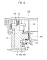
- As a conventional steering lock device, one disclosed in a United Patent Publication US 7, 121, 126 is known. As shown in
Fig. 10 , thesteering lock device 100 has a component housing chamber formed by amain frame 101 and acover 102. In the component housing chamber, alock member 103, acoil spring 104, astopper 105, and atrigger 106 are provided. Thelock member 103 shifts between its lock position for prohibiting rotation of a steering shaft (not shown) and its unlock position for allowing the rotation of the steering shaft. Thecoil spring 104 urges thelock member 103 toward a lock direction (downward inFig. 10 ). Thestopper 105 can hold the lock member at the lock position. The rod-shaped trigger 106 is formed integrally with thecover 102 and can hold thestopper 105 in its inoperable state. - In addition, the
stopper 105 includes astopper pin 107 and astopper spring 108. Thestopper pin 107 is held movably in a direction perpendicular to a moving direction of thelock member 103, and can be inserted into arecess 103a of thelock member 103. Thestopper spring 108 is composed of a coil spring that urges thestopper pin 107 toward thelock member 103. Note that, although thestopper pin 107 is urged toward the lock member 103 (leftward inFig. 10 ) by thestopper spring 108, it is normally held in a state where thestopper 105 is inoperable due to engagement between an end of thetrigger 106 and thestopper pin 107. - By locking the steering shaft using the
lock member 103, theft of a parked vehicle can be prevented. Even if thecover 102 is removed from themain frame 101 in order to directly operate thelock member 103 toward its unlock position, thetrigger 106 is pulled out together with the cover, so that thestopper pin 107 is moved by thestopper spring 108 and thereby inserted into therecess 103a. As a result, since thelock member 103 is held at its lock position, an improper unlock of thelock member 103 can be restricted and thereby a forcible unlock of a lock state of the steering shaft can be prevented. - However, in the above
steering lock device 100, there may be a probability of a removal of thestopper spring 108 due to an insertion of something from atrigger hole 109 opened after pulling-out of thetrigger 106 together with thecover 102. Since thestopper pin 107 can be moved due to the removal of thetopper spring 108, it can be unlocked by pulling-out of thelock member 103 after disengagement between thestopper pin 107 and thelock member 103. - Therefore, an object of the present invention is to provide a steering lock device that can prevent an improper unlock of a lock member by holding the lock member at its lock position even if a stopper spring that urges a stopper pin is removed and thereby prevent thief of a parked vehicle.
- An aspect of the present invention provides a steering lock device that includes a lock member that is disposed in a lock insertion hole formed on a main frame, and can slide between a lock position for prohibiting rotation of a steering shaft and a unlock position for allowing the rotation of the steering shaft; a pin insertion portion formed on the lock member; a stopper pin that is housed in a stopper housing portion formed on the main frame, can slide between an unlatch position for allowing slide of the lock member and a latch position for holding the lock member at the lock position by engaging with the pin insertion portion, and is urged from the unlatch position toward the latch position by a stopper spring housed in the stopper housing portion; and a trigger that is detachably disposed on the main frame, and holds the stopper pin at the unlatch position by contacting with the stopper pin. First stepped portions for engaging with the stopper pin positioning at the latch position are disposed in a side of the unlock position, around an opening of the stopper housing portion and on a wall surface of the lock insertion hole facing to the opening.
- According to the above aspect, the first stepped portions for engaging with the stopper pin positioning at the latch position are disposed in the side of the unlock position, around the opening of the stopper housing portion and on the wall surface of the lock insertion hole facing to the opening. Therefore, when the stopper spring is removed together with the trigger in order to move the lock member toward the unlock position, the stopper pin moves together with the lock member to engage with the first stepped portions. As a result, the stopper pin is not brought back to the unlatch position and the lock member is firmly held at the lock position. Therefore, even when the stopper spring is removed together with the trigger, the lock member is firmly held at the lock position, so that an improper unlock of the lock member is prevented and theft of a parked vehicle can be prevented.
- Here, it is preferable that second stepped portions for engaging with the stopper pin positioning at the latch position are disposed in a side of the lock position, around the opening of the stopper housing portion and on the wall surface of the lock insertion hole facing to the opening.
- According to this, the second stepped portions for engaging with the stopper pin positioning at the latch position are disposed in the side of the lock position, around the opening of the stopper housing portion and on the wall surface of the lock insertion hole facing to the opening. Therefore, when the stopper spring is removed together with the trigger, the stopper pin drops downward due to its own weight with inserted into the pin insertion portion to engage with the second stepped portions. As a result, the stopper pin is not brought back to the unlatch position and the lock member is firmly held at the lock position. Therefore, an improper unlock of the lock member is prevented more effectively and theft of a parked vehicle can be prevented more effectively.
- In addition, it is preferable that a direction perpendicular to both a slide direction of the lock member and a slide direction of the stopper pin is defined as a first direction is assumed as a first direction, third stepped portions for engaging with the stopper pin positioning at the latch position are disposed in a side of the first direction, around the opening of the stopper housing portion and on the wall surface of the lock insertion hole facing to the opening, and a sloped portion sloped along the first direction is disposed at the pin insertion portion of the lock member.
- According to this, the third stepped portions for engaging with the stopper pin positioning at the latch position are disposed in a side of the first direction, around the opening of the stopper housing portion and on the wall surface of the lock insertion hole facing to the opening. In addition, the sloped portion sloped along the first direction is disposed at the pin insertion portion of the lock member. Therefore, when the stopper spring is removed together with the trigger in order to move the lock member toward the unlock position, the stopper pin is moved by the sloped portion to engage with the third stepped portions. As a result, the stopper pin is not brought back to the unlatch position and the lock member is firmly held at the lock position. Therefore, an improper unlock of the lock member is prevented more effectively and theft of a parked vehicle can be prevented more effectively.
- Further, it is preferable that the stopper pin has an almost cylindrical shape, and a center portion of the sloped portion has a chevron shape projected from the lock side toward the unlock side.
- According to this, since the stopper pin never stays at the top of the chevron-shaped sloped portion, the stopper pin is not brought back to the unlatch position and the lock member is firmly held at the lock position. Therefore, an improper unlock of the lock member is prevented more effectively and theft of a parked vehicle can be prevented more effectively.
-
- [
Fig. 1 ] is a perspective view of a steering lock device according to an embodiment of the present invention. - [
Fig. 2 ] is a partial plan of a component housing chamber in the steering lock device according to the embodiment of the present invention. - [
Fig. 3 ] (a) is a side view of the steering lock device according to the steering lock device of the present invention and (b) is a bottom view. - [
Fig. 4 ] is a cross-sectional view (cover is attached) taken along a line IV-IV shown inFig. 3(b) . - [
Fig. 5 ] is a cross-sectional view (cover is removed) taken along the line IV-IV shown inFig. 3(b) . - [
Fig. 6 ] is a cross-sectional view taken along a line VI-VI shown inFig. 5 . - [
Fig. 7 ] is a partially enlarged view of a section VII showing inFig. 6 . - [
Fig. 8 ] is a cross-sectional view (a state where a lock member is about to be pulled out after the cover is removed) taken along the line IV-IV shown inFig. 3(b) . - [
Fig. 9 ] is a partially enlarged view of the section VII showing inFig. 6 (the state where the lock member is about to be pulled out after the cover is removed). - [
Fig. 10 ] is a cross-sectional view of a conventional steering lock device. - Hereinafter, a steering lock device according to an embodiment of the present invention will be explained with reference to the drawings.
- As shown in
Fig. 1 , thesteering lock device 1 according to the present embodiment includes amain frame 2 and acover 3. Themain frame 2 and thecover 3 are attached with each other to form a component housing chamber 3a therein. In addition, thesteering lock device 1 includes alock member 4, an actuator 5, a coil spring (an urging unit) 6, a stopper 7, and a trigger 8 (seeFig. 4 ). Thelock member 4 shifts between its lock position for prohibiting rotation of a steering shaft (not shown) and its unlock position for allowing the rotation of the steering shaft. The actuator 5 is disposed in the component housing chamber 3a and shifts thelock member 4 toward the lock position or the unlock position. Thecoil spring 6 is attached to the inside of thecover 3 to urge thelock member 4 toward a lock direction (downward inFig. 4 ). The stopper 7 can hold thelock member 4 at the lock position. Thetrigger 8 is formed integrally on an inner surface of thecover 3 and can hold the stopper 7 in an inoperable state (at an unlatch position). - As shown in
Figs. 1 to 4 , alock insertion hole 2a, atrigger insertion hole 2b and a subframe attachment portion 2c are provided on themain frame 2. Thelock member 4 is slidably inserted into thelock insertion hole 2a. Thetrigger 8 is slidably inserted into thetrigger insertion hole 2b. Asub frame 11 is attached to the subframe attachment portion 2c. An after-mentionedstopper housing portion 14 is opened on a wall surface of thelock insertion hole 2a. - First stepped
portions 21, second steppedportion 22, and third steppedportions 23 are formed in thestopper housing portion 14. The first steppedportions 21 are disposed in an unlock side (upper side inFig. 4 ) of thelock member 4 at an opening of thestopper housing portion 14 on an inner surface of thelock insertion hole 2a. The second steppedportions 22 are disposed in a lock side (lower side inFig. 4 ) of thelock member 4 at the above-mentioned opening. The third steppedportions 23 are disposed in lateral sides (left/right sides inFig. 6 ) at the above-mentioned opening. Astopper pin 12 can be engaged with the first steppedportions 21, the second steppedportions 22, and the third steppedportions 23. Note that, when a direction perpendicular to both a slide direction of the lock member and a slide direction of thestopper pin 12 is defined as a first direction, the third steppedportions 23 are located on the first direction (lateral direction inFig. 6 ) at the above-mentioned opening. - As shown in
Fig. 1 , thelock member 4 is a rigid planar member, and anengagement end 4b and a spring receive portion 4c are formed thereon. Theengagement end 4b is formed at a tip end of thelock member 4, and can be engaged with a steering shaft. The spring receive portion 4c is formed at a base end, and contacted with thecoil spring 6. Thelock member 4 is disposed within thelock insertion hole 2a formed on themain frame 2. Thelock member 4 can slide between the lock position for prohibiting rotation of the steering shaft and the unlock position for allowing the rotation of the steering shaft. - In addition, a
pin insertion portion 4a is formed on thelock member 4. Thepin insertion portion 4a is formed so as to penetrate thelock member 4 in its thickness direction (the slide direction of the stopper pin 12). In the present embodiment, thepin insertion portion 4a is formed as a cutout on an edge extending along the slide direction of the lock member 4 (seeFig. 7 ). A slopedportion 4d that is sloped along the above-mentioned first direction is provided on an inner surface on a lock side (lower inFig. 7 ) of thepin insertion portion 4a. The center portion of the slopedportion 4d is formed as a chevron shape projected from the lock side toward the unlock side (upper inFig. 7 ). Note that, although thepin insertion portion 4a is formed as a cutout in the present embodiment, it may be formed as a through hole. - As shown in
Fig. 1 , the stopper 7 is composed of thesub frame 11, thestopper pin 12, and astopper spring 13. Thesub frame 11 includes the cylindricalstopper housing portion 14. Thesub frame 11 is to be attached to themain frame 2. Thestopper housing portion 14 intersects perpendicularly to thelock insertion hole 2a in a state where thesub frame 11 is attached to themain frame 2. Thestopper pin 12 and thestopper spring 13 are housed in thestopper housing portion 14. - As show in
Figs. 4 and5 , thestopper pin 12 has a bottomed tube shape. Thestopper pin 12 slides between an unlatch position (Fig. 4 ) located inside of thestopper housing portion 14 and a latch position (Fig. 5 ) located outside of thestopper housing portion 14. The stopper spring (coil spring in the present embodiment) 13 is housed in the inside of thestopper pin 12. Thestopper pin 12 is urged from the unlatch position toward the latch position (rightward inFig. 4 ) by thestopper spring 13. While thestopper pin 12 positions at the unlatch position, thestopper pin 12 and thelock member 4 is not engaged with each other even if thelock member 4 is at any position (seeFig. 4 ). On the other hand, when thestopper pin 12 positions at the latch position, thestopper pin 12 locates within thepin insertion portion 4a of thelock member 4 positioning at the lock position (seeFig. 5 ). - As shown in
Fig. 4 , thetrigger 8 is detachable from themain frame 2. Thetrigger 8 is inserted into thetrigger insertion hole 2b provided on themain frame 2 at ordinary times. In the state where thetrigger 8 is inserted in thetrigger insertion hole 2b, atip end 8a of thetrigger 8 contacts with anend surface 12a of thestopper 12 being inside thestopper housing portion 14, so that thestopper 12 is held at the unlatch position. At this state, thestopper spring 13 is compressed within thestopper pin 12. - Next, behaviors of the above-described
steering lock device 1 will be explained. While the steering shaft is locked with thelock member 4 being at the lock position, the stopper 7 is held in an inoperable state by the trigger 8 (seeFig. 4 ). When thecover 3 is removed from themain frame 2, thetrigger 8 integrally formed with thecover 3 and thecoil spring 6 are also removed. As a result, the contact between the tip end of thetrigger 8 and thestopper pin 12 is released and then thestopper pin 12 is moved to the latch position by thestopper spring 13. Thestopper pin 12 is rushed into thepin insertion portion 4a of the lock member 4 (seeFig. 5 ). If it is tried to pull out thelock member 4 under this state, thelock member 4 is cannot be pulled away and held at the lock position because thestopper pin 12 and thelock member 4 are latched with each other and both ends of thestopper pin 12 are stuck on the first steppedportions 21. - In addition, if the
stopper spring 13 is removed away through thetrigger insertion hole 2b under the above-mentioned state, thestopper pin 12 will drop downward and contacts with the second steppedportions 22. Then, thestopper pin 12 is prevented from moving toward the unlatch position and held at the latch position due to the contact between thestopper pin 12 and the second steppedportions 22. Therefore, the engagement between thestopper pin 12 and thelock member 4 is maintained, so that thelock member 4 is held at the lock position without pulled away (seeFigs. 5 to 7 ). - Further, if it is tried to disengage the
lock member 4 and the second steppedportions 22 in order to move thestopper pin 12 toward the unlatch position by moving thelock member 4 to lift up thestopper pin 12, thestopper pin 12 is pushed out to the third steppedportion 23 by the slopedportion 4d (seeFig. 9 ). Since thestopper pin 12 is stuck on the third steppedportion 23, it cannot be moved toward the unlatch position. In addition, if it will be tried to move thestopper pin 12 by generating vibrations, thestopper pin 12 will moved to an opposite-side slope due to the chevron shape of the slopedportion 4d. Therefore, thestopper pin 12 cannot be moved toward the unlatch position if the vibrations will be generated, and is held at the latch position. In this manner, the engagement between thestopper pin 12 and thelock member 4 is firmly maintained, so that thelock member 4 cannot be pulled away and is held at the lock position. - As explained above, in the present invention embodiment, not only when the
cover 3 is removed from themain frame 2 but also when thestopper spring 13 is removed, thestopper pin 12 is stuck on each of the steppedportions lock member 4 at the lock position. As a result, an improper unlock of thelock member 4 can be prevented and then theft of a parked vehicle can be prevented. - In the above embodiment, the stepped portions are disposed around the opening of the stopper housing portion and on the wall surface of the lock insertion hole facing to the opening, respectively. By this simple structure, an improper unlock can be prevented without increasing the number of components.
- In addition, by providing the sloped
portion 4d sloped along the above-mentioned first direction on thepin insertion portion 4a and forming thestopper pin 12 almost cylindrically-shaped, thestopper pin 12 can be shifted along the first direction by the slopedportion 4d to be stuck on the third steppedportion 23 even when it is tried to move thelock member 4 toward the unlock position by removing thestopper spring 13. Therefore, thestopper pin 12 cannot moved to the unlock position, so that the lock member can be held at the lock position. As a result, an improper unlock of thelock member 4 can be prevented more effectively and then theft of a parked vehicle can be prevented more effectively. Further, thestopper pin 12 never stay at a top of the chevron-shapedsloped portion 4d, so that thestopper pin 12 cannot be moved to unlock position and then the lock member can be held at the lock position firmly. According to this, an improper unlock of the lock member can be prevented more effectively. - Although the preferred embodiment according to the present invention was described above, the present invention is not limited the above embodiment and can be modified variously. For example, although the
trigger 8 and thecover 3 are formed integrally in the above embodiment, thetrigger 6 and thecoil spring 6 may be formed integrally.
Claims (6)
- A steering lock device comprising:a lock member that is disposed in a lock insertion hole formed on a main frame, and can slide between a lock position for prohibiting rotation of a steering shaft and a unlock position for allowing the rotation of the steering shaft;a pin insertion portion formed on the lock member;a stopper pin that is housed in a stopper housing portion formed on the main frame, can slide between an unlatch position for allowing slide of the lock member and a latch position for holding the lock member at the lock position by engaging with the pin insertion portion, and is urged from the unlatch position toward the latch position by a stopper spring housed in the stopper housing portion; anda trigger that is detachably disposed on the main frame, and holds the stopper pin at the unlatch position by contacting with the stopper pin, whereinfirst stepped portions for engaging with the stopper pin positioning at the latch position are disposed in a side of the unlock position, around an opening of the stopper housing portion and on a wall surface of the lock insertion hole facing to the opening.
- The steering lock device according to claim 1, wherein
second stepped portions for engaging with the stopper pin positioning at the latch position are disposed in a side of the lock position, around the opening of the stopper housing portion and on the wall surface of the lock insertion hole facing to the opening. - The steering lock device according to claim 1, wherein
a direction perpendicular to both a slide direction of the lock member and a slide direction of the stopper pin is defined as a first direction is assumed as a first direction,
third stepped portions for engaging with the stopper pin positioning at the latch position are disposed in a side of the first direction, around the opening of the stopper housing portion and on the wall surface of the lock insertion hole facing to the opening, and
a sloped portion sloped along the first direction is disposed at the pin insertion portion of the lock member. - The steering lock device according to claim 2, wherein
a direction perpendicular to both a slide direction of the lock member and a slide direction of the stopper pin is defined as a first direction is assumed as a first direction,
third stepped portions for engaging with the stopper pin positioning at the latch position are disposed in a side of the first direction, around the opening of the stopper housing portion and on the wall surface of the lock insertion hole facing to the opening, and
a sloped portion sloped along the first direction is disposed at the pin insertion portion of the lock member. - The steering lock device according to claim 3, wherein
the stopper pin has an almost cylindrical shape, and
a center of the sloped portion has a chevron shape projected from the lock side toward the unlock side. - The steering lock device according to claim 4, wherein
the stopper pin has an almost cylindrical shape, and
a center portion of the sloped portion has a chevron shape projected from the lock side toward the unlock side.
Applications Claiming Priority (2)
| Application Number | Priority Date | Filing Date | Title |
|---|---|---|---|
| JP2008235005A JP5385571B2 (en) | 2008-09-12 | 2008-09-12 | Steering lock device |
| PCT/JP2009/065901 WO2010029990A1 (en) | 2008-09-12 | 2009-09-11 | Steering lock device |
Publications (3)
| Publication Number | Publication Date |
|---|---|
| EP2330000A1 true EP2330000A1 (en) | 2011-06-08 |
| EP2330000A4 EP2330000A4 (en) | 2013-02-27 |
| EP2330000B1 EP2330000B1 (en) | 2015-04-22 |
Family
ID=42005240
Family Applications (1)
| Application Number | Title | Priority Date | Filing Date |
|---|---|---|---|
| EP20090813136 Not-in-force EP2330000B1 (en) | 2008-09-12 | 2009-09-11 | Steering lock device |
Country Status (4)
| Country | Link |
|---|---|
| US (1) | US8646295B2 (en) |
| EP (1) | EP2330000B1 (en) |
| JP (1) | JP5385571B2 (en) |
| WO (1) | WO2010029990A1 (en) |
Cited By (2)
| Publication number | Priority date | Publication date | Assignee | Title |
|---|---|---|---|---|
| EP2842818A4 (en) * | 2012-04-27 | 2015-12-30 | Alpha Corp | DIRECTION LOCKING DEVICE |
| GB2533025A (en) * | 2014-09-30 | 2016-06-08 | U-Shin Ltd | Steering lock device |
Families Citing this family (13)
| Publication number | Priority date | Publication date | Assignee | Title |
|---|---|---|---|---|
| DE102007034481A1 (en) * | 2007-07-20 | 2009-01-22 | Huf Hülsbeck & Fürst Gmbh & Co. Kg | Locking device with locking part |
| US8424348B2 (en) * | 2010-01-27 | 2013-04-23 | Strattec Security Corporation | Steering lock |
| FR2978403A1 (en) * | 2011-07-25 | 2013-02-01 | Valeo Securite Habitacle | ANTI-THEFT DEVICE FOR STEERING COLUMN AND STEERING COLUMN THEREFOR |
| JP5935115B2 (en) * | 2011-11-28 | 2016-06-15 | 株式会社ユーシン | Electric steering lock device |
| FR2984822B1 (en) * | 2011-12-21 | 2014-04-11 | Valeo Securite Habitacle | STEERING ANTI-THEFT FOR MOTOR VEHICLE WITH SUPERCONDAMNATION AND ASSOCIATED MOUNTING METHOD |
| JP5956819B2 (en) * | 2012-04-27 | 2016-07-27 | 株式会社アルファ | Steering lock device |
| DE102013217735A1 (en) | 2012-09-07 | 2014-03-13 | Strattec Security Corporation | steering lock |
| US8966948B2 (en) * | 2012-12-03 | 2015-03-03 | Hyundai Motor Company | Electrical steering column lock |
| JP5986909B2 (en) * | 2012-12-05 | 2016-09-06 | 株式会社アルファ | Steering lock device |
| ITTO20130766A1 (en) * | 2013-09-23 | 2015-03-24 | Trw Automotive Italia S R L | MECHANICAL STEERING LOCK FOR VEHICLES |
| US10093276B2 (en) * | 2013-10-03 | 2018-10-09 | Alpha Corporation | Steering lock device |
| JP6258125B2 (en) * | 2014-05-27 | 2018-01-10 | 株式会社アルファ | Steering lock device |
| JP7002373B2 (en) * | 2018-03-13 | 2022-01-20 | 本田技研工業株式会社 | Mounting structure of vehicle parts |
Family Cites Families (11)
| Publication number | Priority date | Publication date | Assignee | Title |
|---|---|---|---|---|
| US1542560A (en) * | 1921-06-03 | 1925-06-16 | William D Krautter | Lock |
| US2295807A (en) * | 1941-09-22 | 1942-09-15 | Houdaille Hershey Corp | Steering post and ignition lock assembly |
| US2343976A (en) * | 1941-12-19 | 1944-03-14 | Briggs & Stratton Corp | Combined steering post and ignition lock |
| JPH0412842Y2 (en) * | 1986-07-14 | 1992-03-26 | ||
| US5415019A (en) * | 1993-04-08 | 1995-05-16 | Perez; Roberto | Steering column locking apparatus |
| JPH11310104A (en) * | 1998-04-27 | 1999-11-09 | Toyota Motor Corp | Steering lock device |
| US6516640B2 (en) * | 2000-12-05 | 2003-02-11 | Strattec Security Corporation | Steering column lock apparatus and method |
| DE10247803B3 (en) * | 2002-10-14 | 2004-01-29 | Huf Hülsbeck & Fürst Gmbh & Co. Kg | Device for locking the steering spindle of a motor vehicle |
| US7140213B2 (en) * | 2004-02-21 | 2006-11-28 | Strattec Security Corporation | Steering column lock apparatus and method |
| JP5147217B2 (en) | 2006-11-10 | 2013-02-20 | 株式会社アルファ | Steering lock device |
| JP4838183B2 (en) * | 2007-03-27 | 2011-12-14 | 株式会社アルファ | Steering lock device |
-
2008
- 2008-09-12 JP JP2008235005A patent/JP5385571B2/en not_active Expired - Fee Related
-
2009
- 2009-09-11 WO PCT/JP2009/065901 patent/WO2010029990A1/en not_active Ceased
- 2009-09-11 EP EP20090813136 patent/EP2330000B1/en not_active Not-in-force
- 2009-09-11 US US13/062,959 patent/US8646295B2/en not_active Expired - Fee Related
Cited By (3)
| Publication number | Priority date | Publication date | Assignee | Title |
|---|---|---|---|---|
| EP2842818A4 (en) * | 2012-04-27 | 2015-12-30 | Alpha Corp | DIRECTION LOCKING DEVICE |
| GB2533025A (en) * | 2014-09-30 | 2016-06-08 | U-Shin Ltd | Steering lock device |
| GB2533025B (en) * | 2014-09-30 | 2021-06-16 | U Shin Ltd | Steering lock device |
Also Published As
| Publication number | Publication date |
|---|---|
| JP2010064692A (en) | 2010-03-25 |
| EP2330000A4 (en) | 2013-02-27 |
| US20110167885A1 (en) | 2011-07-14 |
| EP2330000B1 (en) | 2015-04-22 |
| US8646295B2 (en) | 2014-02-11 |
| WO2010029990A1 (en) | 2010-03-18 |
| JP5385571B2 (en) | 2014-01-08 |
Similar Documents
| Publication | Publication Date | Title |
|---|---|---|
| EP2330000B1 (en) | Steering lock device | |
| CN101402351B (en) | Electric steering lock device | |
| RU2542808C1 (en) | Steering column locking device | |
| CN103459209B (en) | Lenkradschlossvorrichtung | |
| JP4881843B2 (en) | Steering lock device | |
| JP2005220702A (en) | Remote controller | |
| JP2004353192A (en) | Electronic key system for vehicles | |
| JP5956819B2 (en) | Steering lock device | |
| JP2013125654A (en) | Housing structure for electronic equipment | |
| JP5965202B2 (en) | Steering lock device | |
| JP4912282B2 (en) | Steering lock device | |
| JP2010167927A (en) | Steering lock device | |
| JP5022880B2 (en) | Steering lock device | |
| JP4156303B2 (en) | Locking device | |
| JP2012051440A (en) | Handle device | |
| JP2007038905A (en) | Electric steering lock device | |
| JP4932442B2 (en) | Locking device, method of using the locking device, and storage device with lock | |
| JP2008025145A (en) | Electronic key system portable machine | |
| JP6831736B2 (en) | Steering lock device | |
| JP2006103694A (en) | Foldable container | |
| JP2016089439A (en) | Latch assembly | |
| JPH086988Y2 (en) | Lock device and covering member for the lock device | |
| CN115341814A (en) | Magnetic fastening device | |
| JP2009083642A (en) | Steering lock device | |
| JP2006037460A (en) | Locking device for case |
Legal Events
| Date | Code | Title | Description |
|---|---|---|---|
| PUAI | Public reference made under article 153(3) epc to a published international application that has entered the european phase |
Free format text: ORIGINAL CODE: 0009012 |
|
| 17P | Request for examination filed |
Effective date: 20110316 |
|
| AK | Designated contracting states |
Kind code of ref document: A1 Designated state(s): AT BE BG CH CY CZ DE DK EE ES FI FR GB GR HR HU IE IS IT LI LT LU LV MC MK MT NL NO PL PT RO SE SI SK SM TR |
|
| AX | Request for extension of the european patent |
Extension state: AL BA RS |
|
| DAX | Request for extension of the european patent (deleted) | ||
| A4 | Supplementary search report drawn up and despatched |
Effective date: 20130130 |
|
| RIC1 | Information provided on ipc code assigned before grant |
Ipc: B60R 25/02 20130101AFI20130124BHEP |
|
| 17Q | First examination report despatched |
Effective date: 20130903 |
|
| GRAP | Despatch of communication of intention to grant a patent |
Free format text: ORIGINAL CODE: EPIDOSNIGR1 |
|
| INTG | Intention to grant announced |
Effective date: 20141113 |
|
| GRAS | Grant fee paid |
Free format text: ORIGINAL CODE: EPIDOSNIGR3 |
|
| GRAA | (expected) grant |
Free format text: ORIGINAL CODE: 0009210 |
|
| AK | Designated contracting states |
Kind code of ref document: B1 Designated state(s): AT BE BG CH CY CZ DE DK EE ES FI FR GB GR HR HU IE IS IT LI LT LU LV MC MK MT NL NO PL PT RO SE SI SK SM TR |
|
| REG | Reference to a national code |
Ref country code: GB Ref legal event code: FG4D |
|
| REG | Reference to a national code |
Ref country code: CH Ref legal event code: EP |
|
| REG | Reference to a national code |
Ref country code: AT Ref legal event code: REF Ref document number: 723020 Country of ref document: AT Kind code of ref document: T Effective date: 20150515 |
|
| REG | Reference to a national code |
Ref country code: IE Ref legal event code: FG4D |
|
| REG | Reference to a national code |
Ref country code: DE Ref legal event code: R096 Ref document number: 602009030863 Country of ref document: DE Effective date: 20150603 |
|
| REG | Reference to a national code |
Ref country code: NL Ref legal event code: VDEP Effective date: 20150422 |
|
| REG | Reference to a national code |
Ref country code: AT Ref legal event code: MK05 Ref document number: 723020 Country of ref document: AT Kind code of ref document: T Effective date: 20150422 |
|
| REG | Reference to a national code |
Ref country code: LT Ref legal event code: MG4D |
|
| PG25 | Lapsed in a contracting state [announced via postgrant information from national office to epo] |
Ref country code: NL Free format text: LAPSE BECAUSE OF FAILURE TO SUBMIT A TRANSLATION OF THE DESCRIPTION OR TO PAY THE FEE WITHIN THE PRESCRIBED TIME-LIMIT Effective date: 20150422 |
|
| PG25 | Lapsed in a contracting state [announced via postgrant information from national office to epo] |
Ref country code: LT Free format text: LAPSE BECAUSE OF FAILURE TO SUBMIT A TRANSLATION OF THE DESCRIPTION OR TO PAY THE FEE WITHIN THE PRESCRIBED TIME-LIMIT Effective date: 20150422 Ref country code: NO Free format text: LAPSE BECAUSE OF FAILURE TO SUBMIT A TRANSLATION OF THE DESCRIPTION OR TO PAY THE FEE WITHIN THE PRESCRIBED TIME-LIMIT Effective date: 20150722 Ref country code: FI Free format text: LAPSE BECAUSE OF FAILURE TO SUBMIT A TRANSLATION OF THE DESCRIPTION OR TO PAY THE FEE WITHIN THE PRESCRIBED TIME-LIMIT Effective date: 20150422 Ref country code: HR Free format text: LAPSE BECAUSE OF FAILURE TO SUBMIT A TRANSLATION OF THE DESCRIPTION OR TO PAY THE FEE WITHIN THE PRESCRIBED TIME-LIMIT Effective date: 20150422 Ref country code: ES Free format text: LAPSE BECAUSE OF FAILURE TO SUBMIT A TRANSLATION OF THE DESCRIPTION OR TO PAY THE FEE WITHIN THE PRESCRIBED TIME-LIMIT Effective date: 20150422 Ref country code: PT Free format text: LAPSE BECAUSE OF FAILURE TO SUBMIT A TRANSLATION OF THE DESCRIPTION OR TO PAY THE FEE WITHIN THE PRESCRIBED TIME-LIMIT Effective date: 20150824 |
|
| PG25 | Lapsed in a contracting state [announced via postgrant information from national office to epo] |
Ref country code: IS Free format text: LAPSE BECAUSE OF FAILURE TO SUBMIT A TRANSLATION OF THE DESCRIPTION OR TO PAY THE FEE WITHIN THE PRESCRIBED TIME-LIMIT Effective date: 20150822 Ref country code: AT Free format text: LAPSE BECAUSE OF FAILURE TO SUBMIT A TRANSLATION OF THE DESCRIPTION OR TO PAY THE FEE WITHIN THE PRESCRIBED TIME-LIMIT Effective date: 20150422 Ref country code: LV Free format text: LAPSE BECAUSE OF FAILURE TO SUBMIT A TRANSLATION OF THE DESCRIPTION OR TO PAY THE FEE WITHIN THE PRESCRIBED TIME-LIMIT Effective date: 20150422 Ref country code: GR Free format text: LAPSE BECAUSE OF FAILURE TO SUBMIT A TRANSLATION OF THE DESCRIPTION OR TO PAY THE FEE WITHIN THE PRESCRIBED TIME-LIMIT Effective date: 20150723 |
|
| REG | Reference to a national code |
Ref country code: DE Ref legal event code: R097 Ref document number: 602009030863 Country of ref document: DE |
|
| PG25 | Lapsed in a contracting state [announced via postgrant information from national office to epo] |
Ref country code: EE Free format text: LAPSE BECAUSE OF FAILURE TO SUBMIT A TRANSLATION OF THE DESCRIPTION OR TO PAY THE FEE WITHIN THE PRESCRIBED TIME-LIMIT Effective date: 20150422 Ref country code: DK Free format text: LAPSE BECAUSE OF FAILURE TO SUBMIT A TRANSLATION OF THE DESCRIPTION OR TO PAY THE FEE WITHIN THE PRESCRIBED TIME-LIMIT Effective date: 20150422 |
|
| PLBE | No opposition filed within time limit |
Free format text: ORIGINAL CODE: 0009261 |
|
| STAA | Information on the status of an ep patent application or granted ep patent |
Free format text: STATUS: NO OPPOSITION FILED WITHIN TIME LIMIT |
|
| PG25 | Lapsed in a contracting state [announced via postgrant information from national office to epo] |
Ref country code: SK Free format text: LAPSE BECAUSE OF FAILURE TO SUBMIT A TRANSLATION OF THE DESCRIPTION OR TO PAY THE FEE WITHIN THE PRESCRIBED TIME-LIMIT Effective date: 20150422 Ref country code: CZ Free format text: LAPSE BECAUSE OF FAILURE TO SUBMIT A TRANSLATION OF THE DESCRIPTION OR TO PAY THE FEE WITHIN THE PRESCRIBED TIME-LIMIT Effective date: 20150422 Ref country code: PL Free format text: LAPSE BECAUSE OF FAILURE TO SUBMIT A TRANSLATION OF THE DESCRIPTION OR TO PAY THE FEE WITHIN THE PRESCRIBED TIME-LIMIT Effective date: 20150422 Ref country code: RO Free format text: LAPSE BECAUSE OF NON-PAYMENT OF DUE FEES Effective date: 20150422 |
|
| 26N | No opposition filed |
Effective date: 20160125 |
|
| PG25 | Lapsed in a contracting state [announced via postgrant information from national office to epo] |
Ref country code: MC Free format text: LAPSE BECAUSE OF FAILURE TO SUBMIT A TRANSLATION OF THE DESCRIPTION OR TO PAY THE FEE WITHIN THE PRESCRIBED TIME-LIMIT Effective date: 20150422 Ref country code: IT Free format text: LAPSE BECAUSE OF FAILURE TO SUBMIT A TRANSLATION OF THE DESCRIPTION OR TO PAY THE FEE WITHIN THE PRESCRIBED TIME-LIMIT Effective date: 20150422 Ref country code: LU Free format text: LAPSE BECAUSE OF FAILURE TO SUBMIT A TRANSLATION OF THE DESCRIPTION OR TO PAY THE FEE WITHIN THE PRESCRIBED TIME-LIMIT Effective date: 20150911 |
|
| REG | Reference to a national code |
Ref country code: CH Ref legal event code: PL |
|
| PG25 | Lapsed in a contracting state [announced via postgrant information from national office to epo] |
Ref country code: SI Free format text: LAPSE BECAUSE OF FAILURE TO SUBMIT A TRANSLATION OF THE DESCRIPTION OR TO PAY THE FEE WITHIN THE PRESCRIBED TIME-LIMIT Effective date: 20150422 |
|
| REG | Reference to a national code |
Ref country code: IE Ref legal event code: MM4A |
|
| PG25 | Lapsed in a contracting state [announced via postgrant information from national office to epo] |
Ref country code: IE Free format text: LAPSE BECAUSE OF NON-PAYMENT OF DUE FEES Effective date: 20150911 Ref country code: CH Free format text: LAPSE BECAUSE OF NON-PAYMENT OF DUE FEES Effective date: 20150930 Ref country code: LI Free format text: LAPSE BECAUSE OF NON-PAYMENT OF DUE FEES Effective date: 20150930 |
|
| PG25 | Lapsed in a contracting state [announced via postgrant information from national office to epo] |
Ref country code: BE Free format text: LAPSE BECAUSE OF FAILURE TO SUBMIT A TRANSLATION OF THE DESCRIPTION OR TO PAY THE FEE WITHIN THE PRESCRIBED TIME-LIMIT Effective date: 20150422 |
|
| REG | Reference to a national code |
Ref country code: FR Ref legal event code: PLFP Year of fee payment: 8 |
|
| PG25 | Lapsed in a contracting state [announced via postgrant information from national office to epo] |
Ref country code: MT Free format text: LAPSE BECAUSE OF FAILURE TO SUBMIT A TRANSLATION OF THE DESCRIPTION OR TO PAY THE FEE WITHIN THE PRESCRIBED TIME-LIMIT Effective date: 20150422 |
|
| PG25 | Lapsed in a contracting state [announced via postgrant information from national office to epo] |
Ref country code: BG Free format text: LAPSE BECAUSE OF FAILURE TO SUBMIT A TRANSLATION OF THE DESCRIPTION OR TO PAY THE FEE WITHIN THE PRESCRIBED TIME-LIMIT Effective date: 20150422 Ref country code: HU Free format text: LAPSE BECAUSE OF FAILURE TO SUBMIT A TRANSLATION OF THE DESCRIPTION OR TO PAY THE FEE WITHIN THE PRESCRIBED TIME-LIMIT; INVALID AB INITIO Effective date: 20090911 Ref country code: SM Free format text: LAPSE BECAUSE OF FAILURE TO SUBMIT A TRANSLATION OF THE DESCRIPTION OR TO PAY THE FEE WITHIN THE PRESCRIBED TIME-LIMIT Effective date: 20150422 |
|
| PG25 | Lapsed in a contracting state [announced via postgrant information from national office to epo] |
Ref country code: SE Free format text: LAPSE BECAUSE OF FAILURE TO SUBMIT A TRANSLATION OF THE DESCRIPTION OR TO PAY THE FEE WITHIN THE PRESCRIBED TIME-LIMIT Effective date: 20150422 Ref country code: CY Free format text: LAPSE BECAUSE OF FAILURE TO SUBMIT A TRANSLATION OF THE DESCRIPTION OR TO PAY THE FEE WITHIN THE PRESCRIBED TIME-LIMIT Effective date: 20150422 |
|
| PG25 | Lapsed in a contracting state [announced via postgrant information from national office to epo] |
Ref country code: TR Free format text: LAPSE BECAUSE OF FAILURE TO SUBMIT A TRANSLATION OF THE DESCRIPTION OR TO PAY THE FEE WITHIN THE PRESCRIBED TIME-LIMIT Effective date: 20150422 |
|
| REG | Reference to a national code |
Ref country code: FR Ref legal event code: PLFP Year of fee payment: 9 |
|
| PG25 | Lapsed in a contracting state [announced via postgrant information from national office to epo] |
Ref country code: MK Free format text: LAPSE BECAUSE OF FAILURE TO SUBMIT A TRANSLATION OF THE DESCRIPTION OR TO PAY THE FEE WITHIN THE PRESCRIBED TIME-LIMIT Effective date: 20150422 |
|
| REG | Reference to a national code |
Ref country code: FR Ref legal event code: PLFP Year of fee payment: 10 |
|
| PGFP | Annual fee paid to national office [announced via postgrant information from national office to epo] |
Ref country code: FR Payment date: 20190925 Year of fee payment: 11 Ref country code: DE Payment date: 20190925 Year of fee payment: 11 |
|
| PGFP | Annual fee paid to national office [announced via postgrant information from national office to epo] |
Ref country code: GB Payment date: 20190926 Year of fee payment: 11 |
|
| REG | Reference to a national code |
Ref country code: DE Ref legal event code: R119 Ref document number: 602009030863 Country of ref document: DE |
|
| GBPC | Gb: european patent ceased through non-payment of renewal fee |
Effective date: 20200911 |
|
| PG25 | Lapsed in a contracting state [announced via postgrant information from national office to epo] |
Ref country code: DE Free format text: LAPSE BECAUSE OF NON-PAYMENT OF DUE FEES Effective date: 20210401 Ref country code: FR Free format text: LAPSE BECAUSE OF NON-PAYMENT OF DUE FEES Effective date: 20200930 |
|
| PG25 | Lapsed in a contracting state [announced via postgrant information from national office to epo] |
Ref country code: GB Free format text: LAPSE BECAUSE OF NON-PAYMENT OF DUE FEES Effective date: 20200911 |