EP2329873A1 - A filter support - Google Patents
A filter support Download PDFInfo
- Publication number
- EP2329873A1 EP2329873A1 EP10783188A EP10783188A EP2329873A1 EP 2329873 A1 EP2329873 A1 EP 2329873A1 EP 10783188 A EP10783188 A EP 10783188A EP 10783188 A EP10783188 A EP 10783188A EP 2329873 A1 EP2329873 A1 EP 2329873A1
- Authority
- EP
- European Patent Office
- Prior art keywords
- air permeable
- filter
- carrier tape
- permeable filters
- holding object
- Prior art date
- Legal status (The legal status is an assumption and is not a legal conclusion. Google has not performed a legal analysis and makes no representation as to the accuracy of the status listed.)
- Granted
Links
Images

Classifications
-
- B—PERFORMING OPERATIONS; TRANSPORTING
- B01—PHYSICAL OR CHEMICAL PROCESSES OR APPARATUS IN GENERAL
- B01D—SEPARATION
- B01D39/00—Filtering material for liquid or gaseous fluids
- B01D39/14—Other self-supporting filtering material ; Other filtering material
-
- B—PERFORMING OPERATIONS; TRANSPORTING
- B01—PHYSICAL OR CHEMICAL PROCESSES OR APPARATUS IN GENERAL
- B01D—SEPARATION
- B01D46/00—Filters or filtering processes specially modified for separating dispersed particles from gases or vapours
- B01D46/10—Particle separators, e.g. dust precipitators, using filter plates, sheets or pads having plane surfaces
-
- B—PERFORMING OPERATIONS; TRANSPORTING
- B01—PHYSICAL OR CHEMICAL PROCESSES OR APPARATUS IN GENERAL
- B01D—SEPARATION
- B01D46/00—Filters or filtering processes specially modified for separating dispersed particles from gases or vapours
- B01D46/42—Auxiliary equipment or operation thereof
-
- B—PERFORMING OPERATIONS; TRANSPORTING
- B01—PHYSICAL OR CHEMICAL PROCESSES OR APPARATUS IN GENERAL
- B01D—SEPARATION
- B01D71/00—Semi-permeable membranes for separation processes or apparatus characterised by the material; Manufacturing processes specially adapted therefor
- B01D71/06—Organic material
- B01D71/26—Polyalkenes
- B01D71/261—Polyethylene
-
- B—PERFORMING OPERATIONS; TRANSPORTING
- B01—PHYSICAL OR CHEMICAL PROCESSES OR APPARATUS IN GENERAL
- B01D—SEPARATION
- B01D71/00—Semi-permeable membranes for separation processes or apparatus characterised by the material; Manufacturing processes specially adapted therefor
- B01D71/06—Organic material
- B01D71/26—Polyalkenes
- B01D71/262—Polypropylene
-
- B—PERFORMING OPERATIONS; TRANSPORTING
- B01—PHYSICAL OR CHEMICAL PROCESSES OR APPARATUS IN GENERAL
- B01D—SEPARATION
- B01D71/00—Semi-permeable membranes for separation processes or apparatus characterised by the material; Manufacturing processes specially adapted therefor
- B01D71/06—Organic material
- B01D71/30—Polyalkenyl halides
- B01D71/32—Polyalkenyl halides containing fluorine atoms
-
- B—PERFORMING OPERATIONS; TRANSPORTING
- B01—PHYSICAL OR CHEMICAL PROCESSES OR APPARATUS IN GENERAL
- B01D—SEPARATION
- B01D71/00—Semi-permeable membranes for separation processes or apparatus characterised by the material; Manufacturing processes specially adapted therefor
- B01D71/06—Organic material
- B01D71/30—Polyalkenyl halides
- B01D71/32—Polyalkenyl halides containing fluorine atoms
- B01D71/36—Polytetrafluoroethylene
-
- B—PERFORMING OPERATIONS; TRANSPORTING
- B01—PHYSICAL OR CHEMICAL PROCESSES OR APPARATUS IN GENERAL
- B01D—SEPARATION
- B01D2265/00—Casings, housings or mounting for filters specially adapted for separating dispersed particles from gases or vapours
- B01D2265/06—Details of supporting structures for filtering material, e.g. cores
-
- Y—GENERAL TAGGING OF NEW TECHNOLOGICAL DEVELOPMENTS; GENERAL TAGGING OF CROSS-SECTIONAL TECHNOLOGIES SPANNING OVER SEVERAL SECTIONS OF THE IPC; TECHNICAL SUBJECTS COVERED BY FORMER USPC CROSS-REFERENCE ART COLLECTIONS [XRACs] AND DIGESTS
- Y10—TECHNICAL SUBJECTS COVERED BY FORMER USPC
- Y10S—TECHNICAL SUBJECTS COVERED BY FORMER USPC CROSS-REFERENCE ART COLLECTIONS [XRACs] AND DIGESTS
- Y10S493/00—Manufacturing container or tube from paper; or other manufacturing from a sheet or web
- Y10S493/941—Filter
Definitions
- the present invention relates to a filter-holding object in which a plurality of air permeable filters are held on a carrier tape.
- a housing accommodating electronic parts, control boards, etc. has an opening try alleviate the pressure fluctuation in the housing and ventilate the inside of the housing, and the opening is closed with an air permeable filter.
- the air permeable filter ensures ventilation between the inside and the outside of the housing and prevents the entry of foreign substances into the housing.
- such an air permeable filter may be adhered directly to the housing as shown in FIG. 3 of Patent Literature 1, or may be adhered to a support body to be attached to the housing as shown in FIG. 5 of Patent Literature 1.
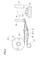
- a filter-holding object 10 in which air permeable filters 30 are held on a carrier tape 20 is prepared, the filter-holding object 10 is wound around a core body 51 to form a reel.
- the carrier tape 20 travels along a knife-edge-shaped peeling table 52, and then is taken up by a take-up roll 53.
- a tension roller 54 applies a proper tension to the carrier tape 20.
- the take-up roll 53 is rotated, the filter-holding object 10 is pulled out from the reel and the air permeable filters 30 each are peeled from the carrier tape 20 at an end of the peeling table 52.
- an opening body 7 that is the housing or the support body is placed on a mounting table 63.
- the air permeable filter 30 partly peeled from the carrier tape 20 is picked up by an absorption nozzle 61, and then conveyed onto the opening body 7. Thereafter, the air permeable filter 30 is adhered to the opening body 7 by, for example, an ultrasonic welding machine 62.
- the present invention is intended to provide a filter-holding object that allows air permeable filters to be peeled from a carrier tape in a satisfactory manner without increasing the tension applied to the carrier tape.
- the present, investor has made intensive studies.
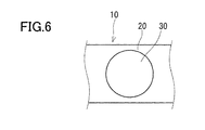
- the inventor has conceived that the above-mentioned problem can be by determining the shape or the air permeable filter appropriately. More specifically, the inventor has conceived that the fact that the conventional air permeable filter 30 has a circular shape as shown in FIG. 6 makes it hard to peel the air permeable filter 30.
- the present invention has been accomplished from this view point.
- the present invention provides a filter-holding object including: a carrier tape extending in a specified direction, and a plurality of air permeable filters held on the carrier tape so as to be arranged in the specified direction.
- the air permeable filters are shaped so that an end portion of each of the air permeable filters on one side of the specified direction is sharpened toward the one side of the specified direction at an angle of 90 degrees or more.
- a filter-holding object 1 includes a carrier tape 2 extending in a specified direction, and a plurality of air permeable filters 3 held on the carrier tape 2.
- the specified direction that is, a longitudinal direction of the carrier tape 2 is referred to as an X direction.
- the X direction is referred to as a +X direction
- the other side opposite to the +X direction is referred to as a -X direction.
- the filter-holding object 1 preferably is formed into a reel.
- an end of the carrier tape 2 in the -X direction is fixed to the core body 51 and then the filter-holding object 1 is wound around the core body 51.
- the +X direction is also a direction in which the filter-holding object 1 is pulled out from the reel.
- the air permeable filters 3 are held on the carrier tape 2 so as to be arranged in the X direction.
- the air permeable filters 3 are arranged straight in a row.
- the air permeable filters 3 may be arranged in a staggered manner, for example.
- the carrier tape 2 has a relatively low adhesive strength on a surface on which the air permeable filters 3 are held.
- the carrier tape 2 holds the air permeable filters 3 with adhesive strength.
- the carrier tape 2 there can be used a carrier tape obtained buy applying an adhesive to a substrate.
- the substrate may be composed of, for example: a resin film made of polyester such as PET (polyethylene terephthalate) and polybutylene terephthalate, polyolefin such as polypropylene, polyethylene and polymethylpentene, and polycarbonate; paper such as fine paper, coated paper, impregnated paper and a synthetic paper, and a metal foil of aluminum, stainless steel or the like.
- an acrylic adhesive can be used for example.
- the carrier tape 2 has a thickness of 0.01 mm to 0.1 mm, and more preferably 0.02 mm to 0.08 mm.
- the carrier tape 2 holds the air permeable filters 3 by using a double-sided tape 4 as will be described later, the carrier tape 2 can be composed only of the substrate with no adhesive applied thereto.
- each of the air permeable filters 3 are not particularly limited as long as they allow air to permeate through the air permeable filters 3.
- an air permeable filter including a resin porous membrane can be used suitably.
- the resin porous membrane there can be used a fluororesin porous membrane, a polyolefin porous membrane, etc. that can be produced by a known method such as a drawling method and an extraction method.
- fluororesin examples include PTFE (polytetrafluoroethylene), polychlorotrifluoroethylene, a tetrafluoroethylene-hexafluoropropylene copolymer, a tetrafluoroethylene-perfluoroalkylvinylether copolymer, and a tetrafluoroethylene-ethylene copolymer.
- a monomer forming the polyolefin include ethylene, propylene, 4-methylpentene-1,1 butene. It is possible to use polyolefin obtained by simply polymerizing or copolymerizing these monomers.
- a nanofiber film porous body using polyacrylonitrile, nylon, or polylactic acid.
- a PTFE porous membrane that is capable of ensuring air permeability with a small area and furnished with a high function of inhibiting entry of water and dust into a housing.
- a PTFE porous membrane having an air permeability of 0.1 to 500 sec/100 mL in Gurley value, a water pressure resistance of 1.0 kPa or more, and a thickness of 1 ⁇ m to 5 mm as a single body.
- the resin porous membrane may be subject to a liquid-repellent treatment.
- the liquid-repellent treatment can be performed by applying a liquid-repellent to the resin porous membrane, drying, and then curing it.
- the liquid-repellent agent only needs to form a coating film with a lower surface tension than that of the resin porous membrane.
- a liquid-repellent agent containing a polymer having a perfluoroalkyl group is used suitably.
- the liquid-repellent agent can be applied by soaking, spraying, etc.
- An air-permeable supporting member may be stacked on one side of both of the resin porous membrane. Providing such an air-permeable supporting member allows the air permeable filter 3 to have a high strength. Preferably, the air-permeable supporting member has a higher air permeability than that of the resin porous membrane. Specifically, woven fabric, nonwoven fabric, a net, a mesh, etc. can be used as the air-permeable supporting member. Examples of the material of the air-permeable supporting member include polyester, polyethylene, and an aramid resin.
- the resin porous membrane and the air-permeable supporting member are bonded to each other by a common method such as heat wielding and bonding with a bonding agent.
- the resin porous membrane and the air-permeable supporting member are bonded to each other partially, and the area of the bonding portion preferably is 5% to 20% of the total area. This is because the resin porous membrane and the air-permeable supporting member tend to be separated from each other easily when the area of the boding portion is less than 5% of the total area, and the water pressure resistance decreases when the area of the boding portion exceeds 20% of the total area.
- the boding portion is distributed uniformly over the total area.
- the air permeable filters 3 each have a thickness of 0.02 mm to 1 mm.
- the air permeable filters 3 with a thickness of less than 0.02 mm have no stiffness, and the workability at handling the air permeable filters 3 is deteriorated.
- the air permeable filters 3 with a thickness exceeding 1 mm make larger projections and depressions on the filter-holding object 1, making it difficult to form the filter-holding object 1 into a reel.
- a more preferable thickness of each of the air permeable filters 3 is 0.05 mm to 0.3 mm.
- Each of the air permeable filters 3 is shaped so that an end portion in the +X direction is sharpened in the +X direction.
- the angle, at which the end portion in the +X direction is sharpened is at least 90 degrees but not more than 135 degrees.
- each of the air permeable filters 3 may have a shape of a polygon, for example.
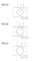
- the polygon may be a regular tetragon as shown in FIG. 1A , a regular pentagon, a regular hexagon as shown in FIG. 1B , a regular heptagon, or a regular octagon as shown in FIG. 1C .
- the air permeable filters 3 may be held and oriented on the carrier tape 2 so that a direction from the center to one vertex of the regular polygon coincides with the +X direction.
- the polygon does not need to be a regular polygon with all its vertices being inscribed in a circle.
- the polygon may be a home-base-shaped pentagon sharpened in the +X direction.
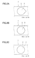
- each of the air permeable filters 3 may have a water drop shape in which a part of a circular portion is projected in the shape of an isosceles triangle.
- FIG. 2A shows a case in which the end portion of the air permeable filter 3 in the +X direction is sharpened at an angle of 90 degrees.
- FIG. 2B shows a case in which the angle is 120 degrees.
- FIG. 2C shows a case in which the angle is 135 degrees.
- the air permeable filters 3 may be held and oriented on the carrier tape 2 so that a direction from the center of the circular portion to the vertex of the isosceles triangle coincides with the +X direction.
- a tip of the end portion of each of the air permeable filters 3 sharpened in the +X direction may be roundish. This configuration makes it possible to reduce the contact area between the end portion of each of the air permeable filters 3 and the carrier tape 2, making it easy to pick up the air permeable filters 3. Thereby, the workability is also enhanced.
- the air permeable filters 3 may be held directly on the carrier tape 2.
- each of the air permeable filters 3 is picked up by the adsorption nozzle 61, conveyed onto the opening body 7, and then adhered to the opening body 7 by, for example, ultrasonic welding using the ultrasonic welding machine 62.
- the air permeable filters 3 each may be held on the carrier tape 2 via the double-sided tape 4.
- the annular double-sided tape 4 is adhered to a surface of each of the air permeable filters 3 facing the carrier tape 2, along a periphery of the surface.
- each of the air permeable filters 3 is adhered to the opening body- 7 the double-sided tape 4 by, for example, being pressed from the top.
- the double-sided tape 4 is not particularly limited as long as it has adhesive strength on both sides.
- each of the air permeable filters 3 does not necessarily have to be adhered to the opening body 7.
- each of the air permeable filters 3 may be attached to the opening body 7 by being integrally molded with a resin after being picked up by the absorption nozzle 61.
- the end portion of each or the air permeable filters 3 is sharpened in the +X direction in the filter-holding object 1 of the present embodiment, the holding strength of the carrier tape 2 for holding the air permeable filters 3 reduces toward the tip of the end portion. Therefore, by allowing the carrier tape 2 to travel along the peeling table 52 (see FIG. 5 ) so that the +X direction coincides with the traveling direction, it is possible to peel the air permeable filters 3 from the carrier tape 2 in a satisfactory manner without increasing the tension applied to the carrier tape 2.
- the filter-holding object 1 thus configured is effective particularly in the case where the air permeable filters 3 each have a low rigidity (for example, in the case where the air permeable filters are PTFE porous membrane monolayers).
- Temish with a thickness of 0.2 mm produced by Nitto Denko Corp. (a product produced by stacking PET nonwoven fabric on a PTFE porous membrane, with a thickness or 0.08 mm).
- the carrier tape there was used a tape obtained by applying an acrylic adhesive to a substrate made of PET with a thickness of 0.08 mm.
- the film was cut into regular polygons, each inscribed in a circle with a diameter of 10 mm, to produce air permeable filters.
- regular polygons There were three types in the regular polygons; regular tetragon, regular hexagon and regular octagon.
- the air permeable filters of each type were held and oriented on the carrier tape so that a direction from the center to one vertex of the regular polygon coincides with a longitudinal direction of the carrier tape.
- filter-holding objects were obtained (Examples 1 to 3).
- Filter-holding objects (Examples 4 to 6) were obtained in the same manner as in Examples 1 to 3, except for that: a substrate with no adhesive applied thereto was used as the carrier tape; and an annular double-sided tape is adhered to a surface of each of the air permeable filters facing the carrier tape, along a periphery of the surface.
- the above-mentioned film was cut into water drop shapes as shown in FIGS. 2A to 2C to produce air permeable filters.
- the water drop shapes each are a shape in which a part of a circular portion is projected in the shape of an isosceles triangle.
- the air permeable filters of each type were held and oriented on the carrier tape so that a direction from the center of the circular portion to the vertex of the isosceles triangle coincides with the longitudinal direction of the carrier tape.
- filter-holding objects were obtained (Examples 7 to 10).
- Filter-holding objects (Examples 11 to 14) were obtained in the same manner as in Examples 7 to 10, except for that: a substrate with no adhesive applied thereto was used as the carrier tape; and an annular double-sided tape is adhered to a surface of each of the air permeable filters facing the carrier tape, along a periphery of the surface.
- a filter-holding object obtained in the same manner as in (Comparative Examples 1, except for that: a substrate with no adhesive applied thereto was used as the carrier tape; and an annular double-sided tape is adhered to a surface of the air permeable filters facing the carrier tape, along a periphery of the surface.
- a filter-holding object (Comparative Example 3) was obtained in the same manner as in Examples 7 to 10, except for that the angle of the vertex of the isosceles triangle in the water drop shape was 80 degrees.
- a filter-holding object (Comparative Example 4) was obtained in the same manner as in Comparative Examples 3, except for that; a substrate with no adhesive applied thereto was used as the carrier tape; and an annular double-sided tape is to a surface of each of the air permeable filters the carrier tape, along a of the surface.
- Example 1 to 14 and Comparative Example to 4 were to by being pulled 90 degrees vertically downward at a constant tension the end of the peeling table as shown it FIG. 4 (the traveling direction with the +X direction shown in FIG. 1 and FIG. 2 .)
- the angle of the peeling table was 30 degrees, and the end of the peeling table was a curved surface with a radius of 0.3 mm.
- the travelling was at various tensions, and measurements were made to find the tension at which the air permeable filters able to be peeled from the carrier tape.
- Table 1 Table 2 show the results thereof.
- the air permeable filters included in the filter-holding object according to the present invention can be used for, for example, outdoor lamps such as outdoor light, and lamps of trains, other than automobile electrical components, household electric appliances and solar cells.
Landscapes
- Chemical & Material Sciences (AREA)
- Chemical Kinetics & Catalysis (AREA)
- Filtering Materials (AREA)
- Separation Using Semi-Permeable Membranes (AREA)
- Filtering Of Dispersed Particles In Gases (AREA)
Abstract


Description
- The present invention relates to a filter-holding object in which a plurality of air permeable filters are held on a carrier tape.
- Conventionally, in automobile electrical components such has automobile ECUs (Electrical Control motors, lamps and sensors, household electric tools such as electric toothbrushes, shavers and mobile phones, and solar cells, for example, a housing accommodating electronic parts, control boards, etc. has an opening try alleviate the pressure fluctuation in the housing and ventilate the inside of the housing, and the opening is closed with an air permeable filter. The air permeable filter ensures ventilation between the inside and the outside of the housing and prevents the entry of foreign substances into the housing.
- For example, such an air permeable filter may be adhered directly to the housing as shown in
FIG. 3 of Patent Literature 1, or may be adhered to a support body to be attached to the housing as shown inFIG. 5 of Patent Literature 1. -
- PTL1
JP 2008-237949 A - In order to produce a large number of housings or support bodies with air permeable filters adhered thereto, it is conceivable to configure a system as in
FIG. 5 . More specifically, a filter-holding object 10 in which airpermeable filters 30 are held on acarrier tape 20 is prepared, the filter-holding object 10 is wound around acore body 51 to form a reel. Thecarrier tape 20 travels along a knife-edge-shaped peeling table 52, and then is taken up by a take-up roll 53. A tension roller 54 applies a proper tension to thecarrier tape 20. When the take-up roll 53 is rotated, the filter-holding object 10 is pulled out from the reel and the airpermeable filters 30 each are peeled from thecarrier tape 20 at an end of the peeling table 52. - On the other hand, an
opening body 7 that is the housing or the support body is placed on a mounting table 63. The airpermeable filter 30 partly peeled from thecarrier tape 20 is picked up by anabsorption nozzle 61, and then conveyed onto theopening body 7. Thereafter, the airpermeable filter 30 is adhered to theopening body 7 by, for example, anultrasonic welding machine 62. - In the system as shown in
FIG. 5 , however, where air permeable filters with low rigidity are used as the airpermeable filters 30, it is hard to peel the airpermeable filters 30 from thecarrier tape 20, raising the possibility of pick-up errors occurring. Specifically, there occurs a phenomenon in which the airpermeable filters 30 are turned back at the end of the peeling table 52 following thecarrier tape 20. In order to prevent this phenomenon, it is conceivable to increase the tension applied to thecarrier tape 20. However, an intricate system configuration is required to make such a tension control possible. Moreover, if the tension applied to thecarrier tape 20 is increased excessively, the airpermeable filters 30 held on thecarrier tape 20 may be deformed. - In view of the foregoing, the present invention is intended to provide a filter-holding object that allows air permeable filters to be peeled from a carrier tape in a satisfactory manner without increasing the tension applied to the carrier tape.
- In order to achieve the above-mentioned purpose, the present, investor has made intensive studies. As a result, the inventor has conceived that the above-mentioned problem can be by determining the shape or the air permeable filter appropriately. More specifically, the inventor has conceived that the fact that the conventional air
permeable filter 30 has a circular shape as shown inFIG. 6 makes it hard to peel the airpermeable filter 30. The present invention has been accomplished from this view point. - specifically, the present invention provides a filter-holding object including: a carrier tape extending in a specified direction, and a plurality of air permeable filters held on the carrier tape so as to be arranged in the specified direction. The air permeable filters are shaped so that an end portion of each of the air permeable filters on one side of the specified direction is sharpened toward the one side of the specified direction at an angle of 90 degrees or more.
- In the above-mentioned configuration, since the end portion of each of the air permeable filters is sharpened toward one side of a longitudinal direction of the carrier tape, the holding strength of the carrier tape for holding the air permeable filters reduces toward a tip of the end portion. Therefore, by allowing the carrier tape to travel along a peeling table so that the direction in which the holding strength reduces coincides with the traveling direction, it is possible to peel the air permeable filters from the carrier tape in a satisfactory manner without increasing the tension applied to the carrier tape.
-
-
FIGS. 1A to 1C each are a plan view of a filter-holding object including a polygonal air permeable filter according to one embodiment of the present Invention. -
FIGs. 2A to 2C each are a plan view of a filter-holding object including a non-polygonal (water-drop-shaped) air permeable filter according to one embodiment of the present invention. -
FIG. 3A is a cross-sectional view of a filter-holding object in which an air permeable filter is held directly on the carrier tape.FIG. 3B is a cross-sectional view of a filter-holding object in which an air permeable filter is held on the carrier tape via a double-sided tape. -
Fig. 4 is a diagram showing a method of a peel test. -
Fig. 5 is a schematic configuration diagram of a production system. -
FIG. 6 is a plan view of a conventional filter-holding object. - Hereinafter, embodiment of the present invention will be described with reference to the accompanying drawings. Since the production system shown in
FIG. 5 described in Technical Problem is used suitably for the filter-holding object of the present invention, the filter-holding object will be described with reference toFIG. 5 below. - As shown in
Fig. 5 , a filter-holding object 1 according to one embodiment of the present invention includes acarrier tape 2 extending in a specified direction, and a plurality of airpermeable filters 3 held on thecarrier tape 2. Hereinafter, in this description, for the convenience of explanation, the specified direction, that is, a longitudinal direction of thecarrier tape 2 is referred to as an X direction. Particularly, one side of the X direction (the side of the traveling direction of thecarrier tape 2 inFIG. 5 ) is referred to as a +X direction, and the other side opposite to the +X direction is referred to as a -X direction. - As shown in
FIG. 5 , the filter-holding object 1 preferably is formed into a reel. In order to form such a reel, an end of thecarrier tape 2 in the -X direction is fixed to thecore body 51 and then the filter-holding object 1 is wound around thecore body 51. More specifically, the +X direction is also a direction in which the filter-holding object 1 is pulled out from the reel. - The air
permeable filters 3 are held on thecarrier tape 2 so as to be arranged in the X direction. Preferably, the airpermeable filters 3 are arranged straight in a row. Alternatively, the airpermeable filters 3 may be arranged in a staggered manner, for example. - The
carrier tape 2 has a relatively low adhesive strength on a surface on which the airpermeable filters 3 are held. Thecarrier tape 2 holds the airpermeable filters 3 with adhesive strength. - As the
carrier tape 2, there can be used a carrier tape obtained buy applying an adhesive to a substrate. The substrate may be composed of, for example: a resin film made of polyester such as PET (polyethylene terephthalate) and polybutylene terephthalate, polyolefin such as polypropylene, polyethylene and polymethylpentene, and polycarbonate; paper such as fine paper, coated paper, impregnated paper and a synthetic paper, and a metal foil of aluminum, stainless steel or the like. As the adhesive, an acrylic adhesive can be used for example. - Preferably the
carrier tape 2 has a thickness of 0.01 mm to 0.1 mm, and more preferably 0.02 mm to 0.08 mm. - In the case where the
carrier tape 2 holds the airpermeable filters 3 by using a double-sided tape 4 as will be described later, thecarrier tape 2 can be composed only of the substrate with no adhesive applied thereto. - The structure and the material of each of the air
permeable filters 3 are not particularly limited as long as they allow air to permeate through the airpermeable filters 3. As the airpermeable filters 3, an air permeable filter including a resin porous membrane can be used suitably. As the resin porous membrane, there can be used a fluororesin porous membrane, a polyolefin porous membrane, etc. that can be produced by a known method such as a drawling method and an extraction method. Examples of the fluororesin include PTFE (polytetrafluoroethylene), polychlorotrifluoroethylene, a tetrafluoroethylene-hexafluoropropylene copolymer, a tetrafluoroethylene-perfluoroalkylvinylether copolymer, and a tetrafluoroethylene-ethylene copolymer. Examples of a monomer forming the polyolefin include ethylene, propylene, 4-methylpentene-1,1 butene. It is possible to use polyolefin obtained by simply polymerizing or copolymerizing these monomers. Alternatively, it is also possible to use, for example, a nanofiber film porous body using polyacrylonitrile, nylon, or polylactic acid. Among all, it is preferable to use a PTFE porous membrane that is capable of ensuring air permeability with a small area and furnished with a high function of inhibiting entry of water and dust into a housing. For example, it is possible to use a PTFE porous membrane having an air permeability of 0.1 to 500 sec/100 mL in Gurley value, a water pressure resistance of 1.0 kPa or more, and a thickness of 1 µm to 5 mm as a single body. - The resin porous membrane may be subject to a liquid-repellent treatment. The liquid-repellent treatment can be performed by applying a liquid-repellent to the resin porous membrane, drying, and then curing it. The liquid-repellent agent only needs to form a coating film with a lower surface tension than that of the resin porous membrane. For Example, a liquid-repellent agent containing a polymer having a perfluoroalkyl group is used suitably. The liquid-repellent agent can be applied by soaking, spraying, etc.
- An air-permeable supporting member may be stacked on one side of both of the resin porous membrane. Providing such an air-permeable supporting member allows the air
permeable filter 3 to have a high strength. Preferably, the air-permeable supporting member has a higher air permeability than that of the resin porous membrane. Specifically, woven fabric, nonwoven fabric, a net, a mesh, etc. can be used as the air-permeable supporting member. Examples of the material of the air-permeable supporting member include polyester, polyethylene, and an aramid resin. - The resin porous membrane and the air-permeable supporting member are bonded to each other by a common method such as heat wielding and bonding with a bonding agent. The resin porous membrane and the air-permeable supporting member are bonded to each other partially, and the area of the bonding portion preferably is 5% to 20% of the total area. This is because the resin porous membrane and the air-permeable supporting member tend to be separated from each other easily when the area of the boding portion is less than 5% of the total area, and the water pressure resistance decreases when the area of the boding portion exceeds 20% of the total area. Preferably, the boding portion is distributed uniformly over the total area.
- Preferable, the air
permeable filters 3 each have a thickness of 0.02 mm to 1 mm. The airpermeable filters 3 with a thickness of less than 0.02 mm have no stiffness, and the workability at handling the airpermeable filters 3 is deteriorated. The airpermeable filters 3 with a thickness exceeding 1 mm make larger projections and depressions on the filter-holding object 1, making it difficult to form the filter-holding object 1 into a reel. A more preferable thickness of each of the airpermeable filters 3 is 0.05 mm to 0.3 mm. - Each of the air
permeable filters 3 is shaped so that an end portion in the +X direction is sharpened in the +X direction. Preferably, the angle, at which the end portion in the +X direction is sharpened is at least 90 degrees but not more than 135 degrees. - As shown in
FIGs. 1A to 1C , each of the airpermeable filters 3 may have a shape of a polygon, for example. The polygon may be a regular tetragon as shown inFIG. 1A , a regular pentagon, a regular hexagon as shown inFIG. 1B , a regular heptagon, or a regular octagon as shown inFIG. 1C . When the polygon is a regular polygon like these, the airpermeable filters 3 may be held and oriented on thecarrier tape 2 so that a direction from the center to one vertex of the regular polygon coincides with the +X direction. The polygon does not need to be a regular polygon with all its vertices being inscribed in a circle. For example, the polygon may be a home-base-shaped pentagon sharpened in the +X direction. - Alternatively, as shown in
FIGs. 2A to 2C , each of the airpermeable filters 3 may have a water drop shape in which a part of a circular portion is projected in the shape of an isosceles triangle.FIG. 2A shows a case in which the end portion of the airpermeable filter 3 in the +X direction is sharpened at an angle of 90 degrees.FIG. 2B shows a case in which the angle is 120 degrees.FIG. 2C shows a case in which the angle is 135 degrees. When the airpermeable filters 3 have a water drop shape like these, the airpermeable filters 3 may be held and oriented on thecarrier tape 2 so that a direction from the center of the circular portion to the vertex of the isosceles triangle coincides with the +X direction. - A tip of the end portion of each of the air
permeable filters 3 sharpened in the +X direction may be roundish. This configuration makes it possible to reduce the contact area between the end portion of each of the airpermeable filters 3 and thecarrier tape 2, making it easy to pick up the airpermeable filters 3. Thereby, the workability is also enhanced. - As shown in
FIG. 3A , the airpermeable filters 3 may be held directly on thecarrier tape 2. In this case, as shown inFig. 5 , each of the airpermeable filters 3 is picked up by theadsorption nozzle 61, conveyed onto theopening body 7, and then adhered to theopening body 7 by, for example, ultrasonic welding using theultrasonic welding machine 62. - Alternatively, as shown in
FIG. 3B , the airpermeable filters 3 each may be held on thecarrier tape 2 via the double-sided tape 4. Specifically, the annular double-sided tape 4 is adhered to a surface of each of the airpermeable filters 3 facing thecarrier tape 2, along a periphery of the surface. In this case, after being conveyed onto theopening body 7 by theadsorption nozzle 61, each of the airpermeable filters 3 is adhered to the opening body- 7 the double-sided tape 4 by, for example, being pressed from the top. - The double-
sided tape 4 is not particularly limited as long as it has adhesive strength on both sides. For example, it is possible to use a tape obtained by applying an acrylic or silicon adhesive to both sides of a Support, layer such as a PET substrate and nonwoven fabric. - Each of the air
permeable filters 3 does not necessarily have to be adhered to theopening body 7. For example, each of the airpermeable filters 3 may be attached to theopening body 7 by being integrally molded with a resin after being picked up by theabsorption nozzle 61. - As described above, the end portion of each or the air
permeable filters 3 is sharpened in the +X direction in the filter-holding object 1 of the present embodiment, the holding strength of thecarrier tape 2 for holding the airpermeable filters 3 reduces toward the tip of the end portion. Therefore, by allowing thecarrier tape 2 to travel along the peeling table 52 (seeFIG. 5 ) so that the +X direction coincides with the traveling direction, it is possible to peel the airpermeable filters 3 from thecarrier tape 2 in a satisfactory manner without increasing the tension applied to thecarrier tape 2. The filter-holding object 1 thus configured is effective particularly in the case where the airpermeable filters 3 each have a low rigidity (for example, in the case where the air permeable filters are PTFE porous membrane monolayers). - Hereinafter, the present invention will be described in detail with reference to examples, but the present invention is not restricted to these examples.
- As a film for producing the air permeable filters, there was prepared Temish with a thickness of 0.2 mm, produced by Nitto Denko Corp. (a product produced by stacking PET nonwoven fabric on a PTFE porous membrane, with a thickness or 0.08 mm). As the carrier tape, there was used a tape obtained by applying an acrylic adhesive to a substrate made of PET with a thickness of 0.08 mm.
- The film was cut into regular polygons, each inscribed in a circle with a diameter of 10 mm, to produce air permeable filters. There were three types in the regular polygons; regular tetragon, regular hexagon and regular octagon. The air permeable filters of each type were held and oriented on the carrier tape so that a direction from the center to one vertex of the regular polygon coincides with a longitudinal direction of the carrier tape. Thus, filter-holding objects were obtained (Examples 1 to 3).
- Filter-holding objects (Examples 4 to 6) were obtained in the same manner as in Examples 1 to 3, except for that: a substrate with no adhesive applied thereto was used as the carrier tape; and an annular double-sided tape is adhered to a surface of each of the air permeable filters facing the carrier tape, along a periphery of the surface.
- Additionally the above-mentioned film was cut into water drop shapes as shown in
FIGS. 2A to 2C to produce air permeable filters. The water drop shapes each are a shape in which a part of a circular portion is projected in the shape of an isosceles triangle. There where four types in the angle of the vertex of the isosceles triangle: 90 degrees, 120 degrees, 135 degrees and 150 degrees. The air permeable filters of each type were held and oriented on the carrier tape so that a direction from the center of the circular portion to the vertex of the isosceles triangle coincides with the longitudinal direction of the carrier tape. Thus, filter-holding objects were obtained (Examples 7 to 10). - Filter-holding objects (Examples 11 to 14) were obtained in the same manner as in Examples 7 to 10, except for that: a substrate with no adhesive applied thereto was used as the carrier tape; and an annular double-sided tape is adhered to a surface of each of the air permeable filters facing the carrier tape, along a periphery of the surface.
- The above-mentioned film was cut into circles with a diameter of 10 mm to produce air permeable filters. These air permeable filters were held on a carrier tape composed of a substrate with an adhesive applied thereto. Thus, a filter-holding object obtained (Comparative Example 1).
- A filter-holding object (Comparative Examples 2) obtained in the same manner as in (Comparative Examples 1, except for that: a substrate with no adhesive applied thereto was used as the carrier tape; and an annular double-sided tape is adhered to a surface of the air permeable filters facing the carrier tape, along a periphery of the surface.
- A filter-holding object (Comparative Example 3) was obtained in the same manner as in Examples 7 to 10, except for that the angle of the vertex of the isosceles triangle in the water drop shape was 80 degrees.
- A filter-holding object (Comparative Example 4) was obtained in the same manner as in Comparative Examples 3, except for that; a substrate with no adhesive applied thereto was used as the carrier tape; and an annular double-sided tape is to a surface of each of the air permeable filters the carrier tape, along a of the surface.
- The filter-holding objects of Example 1 to 14 and Comparative Example to 4 were to by being pulled 90 degrees vertically downward at a constant tension the end of the peeling table as shown it
FIG. 4 (the traveling direction with the +X direction shown inFIG. 1 andFIG. 2 .) The angle of the peeling table was 30 degrees, and the end of the peeling table was a curved surface with a radius of 0.3 mm. The travelling was at various tensions, and measurements were made to find the tension at which the air permeable filters able to be peeled from the carrier tape. Table 1 Table 2 show the results thereof. -
[Table 1] Holding air permeable filters by using an adhesive Shape of air permeable filters Angle of end portion in traveling direction Tension at which air permeable filters were able to be peeled (N) Example 1 Regular tetragon 90 degrees 0.735 Examples 2 Regular hexagon 120 degrees 0.735 Examples 3 Regular octagon 135 degrees 0.735 Examples 7 Water drop shape 90 degrees 0.98 Example 8 Ditto 120 degrees 0.735 Example 9 Ditto 1345 degrees 0.98 Example 10 Ditto 150 degrees 1.47 C. Example 1 Circular - 1.96 C. Example 3 Water drop shape 80 degrees - -
[Table 2] Holding air permeable filters by using a double-sided tape Shape of air permeable filters Angle of end portion in traveling direction Tension at which air permeable filters were able to be peeled (N) Example 4 Regular tetragon 90 degrees 0.735 Example 5 Regular hexagon 120 degrees 0.735 Example 6 Regular octagon 135 degrees 0.735 Example 11 Water drop shape 90 degrees 0.98 Example 12 Ditto 120 degrees 0.735 Example 13 Ditto 135 degrees 0.98 Example 14 Ditto 150 degrees 1.47 C. Example 2 Circular - 1.715 C. Example 4 Water drop shape 80 degrees - - As shown in Table 1, a tension of 1.96 N was required for the air permeable filters to be peeled in Comparative Example 1. In contrast, in Examples 1 to 3 and 7 to 10, the tension at which the air permeable filters were able to be peeled was suppressed to 1.47 N or less. Particularly, when the end portion of each of the air permeable filters in the traveling direction was sharpened at an angle of 135 degrees or less, the tension at which the air permeable filters were able to be peeled was suppressed to as low as 0.98 N or less. A similar tendency also appears in Table 2.
- In Comparative Examples 3 and 4, in which the end portion of each of the air permeable filters in the traveling direction was sharpened at an angle less than 90 degrees, the air permeable filters failed to be peeled from the carrier tape and were turned back together with the carrier tape even when the tension applied to the carrier tape was increased to 1.96 N. Then each of the air permeable filters was flown off from the carrier tape after its center passed the end of the peeling table.
- The air permeable filters included in the filter-holding object according to the present invention can be used for, for example, outdoor lamps such as outdoor light, and lamps of trains, other than automobile electrical components, household electric appliances and solar cells.
Claims (8)
- A filter-holding object comprising:a carrier tape extending in a specified direction; anda plurality of air permeable filters held on the carrier tape so as to be arranged in the specified direction,wherein the air permeable filter are shaped so that an end portion of each of the air permeable filters on one side of the specified direction is sharpened toward the one side of the specified direction at an angle of 90 degrees or more.
- The filter-holding object according to claim 1, wherein the end portion of each of the air permeable filters on the one side of the specified direction is sharpened at an angle of 135 degrees or less.
- The filter-holding object according to claim 1, wherein each of the air permeable filters has a shape of a polygon.
- The filter-holding object according to claim 3, wherein the polygon is a regular tetragon, a regular pentagon, a regular hexagon, a regular heptagon, or a regular octagon.
- The filter-holding object according to claim 1, wherein a tip of the end portion of each of the air permeable filters sharpened in the specified direction is roundish.
- The filter-holding object according to claim 1, wherein each of the air permeable filters includes a resin porous membrane.
- The filter-holding object according to claim 6, wherein each of the air permeable filters further includes a air-permeable supporting member stacked on the resin porous membrane.
- The filter holding object according to claim 1, wherein an annular double-sided tape is adhered to a surface of each of the air permeable filters facing the carrier tape, along a periphery of the surface.
Applications Claiming Priority (2)
| Application Number | Priority Date | Filing Date | Title |
|---|---|---|---|
| JP2009134764A JP5405198B2 (en) | 2009-06-04 | 2009-06-04 | Filter carrier |
| PCT/JP2010/053616 WO2010140402A1 (en) | 2009-06-04 | 2010-03-05 | A filter support |
Publications (3)
| Publication Number | Publication Date |
|---|---|
| EP2329873A1 true EP2329873A1 (en) | 2011-06-08 |
| EP2329873A4 EP2329873A4 (en) | 2014-01-29 |
| EP2329873B1 EP2329873B1 (en) | 2020-09-02 |
Family
ID=43297543
Family Applications (1)
| Application Number | Title | Priority Date | Filing Date |
|---|---|---|---|
| EP10783188.5A Active EP2329873B1 (en) | 2009-06-04 | 2010-03-05 | A filter support |
Country Status (6)
| Country | Link |
|---|---|
| US (1) | US8252083B2 (en) |
| EP (1) | EP2329873B1 (en) |
| JP (1) | JP5405198B2 (en) |
| KR (2) | KR20170044213A (en) |
| CN (2) | CN105214385B (en) |
| WO (1) | WO2010140402A1 (en) |
Families Citing this family (4)
| Publication number | Priority date | Publication date | Assignee | Title |
|---|---|---|---|---|
| EP2915573B1 (en) * | 2014-03-06 | 2016-09-14 | Sefar AG | Method for producing a contoured filter element and filter element assembly |
| CN105664617A (en) * | 2016-04-11 | 2016-06-15 | 徐州工程学院 | Full-automatic filter cartridge type industrial dust removing device and working method thereof |
| CN113557139B (en) * | 2020-01-09 | 2023-01-03 | 日东电工株式会社 | Member feeding sheet |
| KR102395512B1 (en) | 2020-07-16 | 2022-05-09 | 제이엔티(주) | Self Safe braking motor-driven elderly walking assist device |
Family Cites Families (22)
| Publication number | Priority date | Publication date | Assignee | Title |
|---|---|---|---|---|
| US2079297A (en) * | 1936-07-30 | 1937-05-04 | American Radiator Co | Filter |
| US3727769A (en) * | 1971-04-14 | 1973-04-17 | American Air Filter Co | Prestressed filter media |
| US3793692A (en) * | 1972-12-12 | 1974-02-26 | American Air Filter Co | Fluid treating filter |
| DE2751640C2 (en) * | 1977-11-17 | 1987-04-02 | Delbag-Luftfilter Gmbh, 1000 Berlin | Replaceable filter element for cleaning air or gas streams loaded with toxic or radioactive components in nuclear facilities and process for replacing and removing volume-reducible contaminated filter elements in waste containers |
| AU565494B2 (en) * | 1983-10-18 | 1987-09-17 | Nippondenso Co. Ltd. | Filter element |
| JPH0691057B2 (en) * | 1985-09-07 | 1994-11-14 | 日東電工株式会社 | Semiconductor wafer protection member |
| JPS63165271A (en) * | 1986-12-26 | 1988-07-08 | Nitto Electric Ind Co Ltd | Laminating method for viscous film piece |
| JPH01158575A (en) * | 1987-12-15 | 1989-06-21 | Nec Corp | Picture data displaying control system |
| JPH1158575A (en) * | 1997-08-27 | 1999-03-02 | Nitto Denko Corp | Vent structure and method of manufacturing the same |
| JP4371512B2 (en) * | 1999-12-20 | 2009-11-25 | 日東電工株式会社 | Porous film, method for producing the same, and label |
| CN2542663Y (en) * | 2002-04-22 | 2003-04-02 | 联诚兴企业(上海)有限公司 | Adhesive tape with novel structure |
| JP4497453B2 (en) * | 2004-03-16 | 2010-07-07 | 日東電工株式会社 | Vent filter for toner container, vent member, developing device using the same, toner box, and vent filter assembly for toner container |
| JP4590214B2 (en) * | 2004-06-04 | 2010-12-01 | 富士フイルム株式会社 | Adhesive label roll |
| JP4509748B2 (en) * | 2004-11-24 | 2010-07-21 | 日東電工株式会社 | Foam member carrier tape and foam member carrier |
| US7520913B2 (en) * | 2005-02-04 | 2009-04-21 | Donaldson Company, Inc. | Non-cylindrical filter elements, and methods |
| JP4878869B2 (en) * | 2005-04-08 | 2012-02-15 | 日東電工株式会社 | Foamed members, foamed member laminates, and electrical / electronic devices using the foamed members |
| JP5085090B2 (en) * | 2006-10-19 | 2012-11-28 | 日東電工株式会社 | Porous resin membrane with adhesive layer, method for producing the same, and filter member |
| JP4680220B2 (en) | 2007-03-23 | 2011-05-11 | 日東電工株式会社 | Waterproof ventilation filter, waterproof ventilation member and housing |
| US20080264019A1 (en) * | 2007-04-30 | 2008-10-30 | Walker John R | Air filtration system and method |
| US7771517B2 (en) * | 2007-05-14 | 2010-08-10 | Global Finishing Solutions, L.L.C. | Filtering method |
| WO2008156173A1 (en) * | 2007-06-21 | 2008-12-24 | Nitto Denko Corporation | Roll of porous polytetrafluoroethylene sheet and tape roll |
| JP2010000464A (en) * | 2008-06-20 | 2010-01-07 | Japan Gore Tex Inc | Vent filter and method for manufacturing thereof |
-
2009
- 2009-06-04 JP JP2009134764A patent/JP5405198B2/en active Active
-
2010
- 2010-03-05 KR KR1020177010101A patent/KR20170044213A/en not_active Ceased
- 2010-03-05 CN CN201510520932.3A patent/CN105214385B/en active Active
- 2010-03-05 CN CN201080001912.0A patent/CN102065975B/en active Active
- 2010-03-05 WO PCT/JP2010/053616 patent/WO2010140402A1/en not_active Ceased
- 2010-03-05 KR KR1020117010087A patent/KR20120039507A/en not_active Ceased
- 2010-03-05 US US12/989,002 patent/US8252083B2/en active Active
- 2010-03-05 EP EP10783188.5A patent/EP2329873B1/en active Active
Also Published As
| Publication number | Publication date |
|---|---|
| CN105214385B (en) | 2017-04-12 |
| CN102065975B (en) | 2016-03-23 |
| CN102065975A (en) | 2011-05-18 |
| US8252083B2 (en) | 2012-08-28 |
| EP2329873B1 (en) | 2020-09-02 |
| EP2329873A4 (en) | 2014-01-29 |
| WO2010140402A1 (en) | 2010-12-09 |
| KR20170044213A (en) | 2017-04-24 |
| JP5405198B2 (en) | 2014-02-05 |
| JP2010279891A (en) | 2010-12-16 |
| US20110168022A1 (en) | 2011-07-14 |
| KR20120039507A (en) | 2012-04-25 |
| CN105214385A (en) | 2016-01-06 |
Similar Documents
| Publication | Publication Date | Title |
|---|---|---|
| EP2583734B1 (en) | Waterproof air-permeable filter and uses thereof | |
| EP2583733B1 (en) | Waterproof air-permeable filter and use of the same | |
| US9121626B2 (en) | Ventilation member | |
| KR101810079B1 (en) | Antibacterial dressing | |
| EP2329873B1 (en) | A filter support | |
| US20100227544A1 (en) | Vent Member and Vent Structure | |
| KR101896367B1 (en) | Breathable waterproof sheet | |
| CN111065772A (en) | Waterproof and breathable sheet and manufacturing method thereof | |
| EP3613586B1 (en) | Laminate and wound body | |
| JP6184766B2 (en) | Porous laminate, adsorption buffer material, and adsorption method | |
| EP1835227A1 (en) | Permeable member, permeable casing using the permeable member, and electrical part | |
| JP2017154407A (en) | Fiber laminated body and method for producing the same | |
| EP3726947B1 (en) | Internal pressure adjustment member and electrical component for transport device | |
| JP5220709B2 (en) | Filter carrier | |
| KR101812784B1 (en) | Waterproof ventilation sheet and method for manufacturing the same | |
| KR102520977B1 (en) | Laminate and winding body | |
| US12397082B2 (en) | Antimicrobial dressing | |
| JP6522039B2 (en) | Protective film-attached film piece, method of removing protective film of protective film-attached film piece, and method of manufacturing electric device | |
| CN113557139B (en) | Member feeding sheet | |
| CN111051591A (en) | Waterproof and breathable sheet and manufacturing method thereof | |
| KR101812785B1 (en) | Waterproof ventilation sheet and method for manufacturing the same | |
| JP2011161359A (en) | Filter carrier and production system | |
| KR20220167776A (en) | Adsorbent for oil emulsion |
Legal Events
| Date | Code | Title | Description |
|---|---|---|---|
| PUAI | Public reference made under article 153(3) epc to a published international application that has entered the european phase |
Free format text: ORIGINAL CODE: 0009012 |
|
| 17P | Request for examination filed |
Effective date: 20110104 |
|
| AK | Designated contracting states |
Kind code of ref document: A1 Designated state(s): AT BE BG CH CY CZ DE DK EE ES FI FR GB GR HR HU IE IS IT LI LT LU LV MC MK MT NL NO PL PT RO SE SI SK SM TR |
|
| AX | Request for extension of the european patent |
Extension state: AL BA ME RS |
|
| DAX | Request for extension of the european patent (deleted) | ||
| A4 | Supplementary search report drawn up and despatched |
Effective date: 20140108 |
|
| RIC1 | Information provided on ipc code assigned before grant |
Ipc: B01D 71/36 20060101ALI20131220BHEP Ipc: B01D 71/26 20060101AFI20131220BHEP Ipc: B01D 71/32 20060101ALI20131220BHEP Ipc: B01D 46/10 20060101ALI20131220BHEP |
|
| STAA | Information on the status of an ep patent application or granted ep patent |
Free format text: STATUS: EXAMINATION IS IN PROGRESS |
|
| 17Q | First examination report despatched |
Effective date: 20180920 |
|
| GRAP | Despatch of communication of intention to grant a patent |
Free format text: ORIGINAL CODE: EPIDOSNIGR1 |
|
| STAA | Information on the status of an ep patent application or granted ep patent |
Free format text: STATUS: GRANT OF PATENT IS INTENDED |
|
| INTG | Intention to grant announced |
Effective date: 20200318 |
|
| GRAS | Grant fee paid |
Free format text: ORIGINAL CODE: EPIDOSNIGR3 |
|
| GRAA | (expected) grant |
Free format text: ORIGINAL CODE: 0009210 |
|
| STAA | Information on the status of an ep patent application or granted ep patent |
Free format text: STATUS: THE PATENT HAS BEEN GRANTED |
|
| AK | Designated contracting states |
Kind code of ref document: B1 Designated state(s): AT BE BG CH CY CZ DE DK EE ES FI FR GB GR HR HU IE IS IT LI LT LU LV MC MK MT NL NO PL PT RO SE SI SK SM TR |
|
| REG | Reference to a national code |
Ref country code: GB Ref legal event code: FG4D |
|
| REG | Reference to a national code |
Ref country code: AT Ref legal event code: REF Ref document number: 1308180 Country of ref document: AT Kind code of ref document: T Effective date: 20200915 Ref country code: CH Ref legal event code: EP |
|
| REG | Reference to a national code |
Ref country code: DE Ref legal event code: R096 Ref document number: 602010065331 Country of ref document: DE |
|
| REG | Reference to a national code |
Ref country code: IE Ref legal event code: FG4D |
|
| REG | Reference to a national code |
Ref country code: LT Ref legal event code: MG4D |
|
| PG25 | Lapsed in a contracting state [announced via postgrant information from national office to epo] |
Ref country code: FI Free format text: LAPSE BECAUSE OF FAILURE TO SUBMIT A TRANSLATION OF THE DESCRIPTION OR TO PAY THE FEE WITHIN THE PRESCRIBED TIME-LIMIT Effective date: 20200902 Ref country code: GR Free format text: LAPSE BECAUSE OF FAILURE TO SUBMIT A TRANSLATION OF THE DESCRIPTION OR TO PAY THE FEE WITHIN THE PRESCRIBED TIME-LIMIT Effective date: 20201203 Ref country code: NO Free format text: LAPSE BECAUSE OF FAILURE TO SUBMIT A TRANSLATION OF THE DESCRIPTION OR TO PAY THE FEE WITHIN THE PRESCRIBED TIME-LIMIT Effective date: 20201202 Ref country code: SE Free format text: LAPSE BECAUSE OF FAILURE TO SUBMIT A TRANSLATION OF THE DESCRIPTION OR TO PAY THE FEE WITHIN THE PRESCRIBED TIME-LIMIT Effective date: 20200902 Ref country code: HR Free format text: LAPSE BECAUSE OF FAILURE TO SUBMIT A TRANSLATION OF THE DESCRIPTION OR TO PAY THE FEE WITHIN THE PRESCRIBED TIME-LIMIT Effective date: 20200902 Ref country code: LT Free format text: LAPSE BECAUSE OF FAILURE TO SUBMIT A TRANSLATION OF THE DESCRIPTION OR TO PAY THE FEE WITHIN THE PRESCRIBED TIME-LIMIT Effective date: 20200902 Ref country code: BG Free format text: LAPSE BECAUSE OF FAILURE TO SUBMIT A TRANSLATION OF THE DESCRIPTION OR TO PAY THE FEE WITHIN THE PRESCRIBED TIME-LIMIT Effective date: 20201202 |
|
| REG | Reference to a national code |
Ref country code: NL Ref legal event code: MP Effective date: 20200902 |
|
| REG | Reference to a national code |
Ref country code: AT Ref legal event code: MK05 Ref document number: 1308180 Country of ref document: AT Kind code of ref document: T Effective date: 20200902 |
|
| PG25 | Lapsed in a contracting state [announced via postgrant information from national office to epo] |
Ref country code: PL Free format text: LAPSE BECAUSE OF FAILURE TO SUBMIT A TRANSLATION OF THE DESCRIPTION OR TO PAY THE FEE WITHIN THE PRESCRIBED TIME-LIMIT Effective date: 20200902 Ref country code: LV Free format text: LAPSE BECAUSE OF FAILURE TO SUBMIT A TRANSLATION OF THE DESCRIPTION OR TO PAY THE FEE WITHIN THE PRESCRIBED TIME-LIMIT Effective date: 20200902 |
|
| PG25 | Lapsed in a contracting state [announced via postgrant information from national office to epo] |
Ref country code: CZ Free format text: LAPSE BECAUSE OF FAILURE TO SUBMIT A TRANSLATION OF THE DESCRIPTION OR TO PAY THE FEE WITHIN THE PRESCRIBED TIME-LIMIT Effective date: 20200902 Ref country code: EE Free format text: LAPSE BECAUSE OF FAILURE TO SUBMIT A TRANSLATION OF THE DESCRIPTION OR TO PAY THE FEE WITHIN THE PRESCRIBED TIME-LIMIT Effective date: 20200902 Ref country code: SM Free format text: LAPSE BECAUSE OF FAILURE TO SUBMIT A TRANSLATION OF THE DESCRIPTION OR TO PAY THE FEE WITHIN THE PRESCRIBED TIME-LIMIT Effective date: 20200902 Ref country code: RO Free format text: LAPSE BECAUSE OF FAILURE TO SUBMIT A TRANSLATION OF THE DESCRIPTION OR TO PAY THE FEE WITHIN THE PRESCRIBED TIME-LIMIT Effective date: 20200902 Ref country code: PT Free format text: LAPSE BECAUSE OF FAILURE TO SUBMIT A TRANSLATION OF THE DESCRIPTION OR TO PAY THE FEE WITHIN THE PRESCRIBED TIME-LIMIT Effective date: 20210104 Ref country code: NL Free format text: LAPSE BECAUSE OF FAILURE TO SUBMIT A TRANSLATION OF THE DESCRIPTION OR TO PAY THE FEE WITHIN THE PRESCRIBED TIME-LIMIT Effective date: 20200902 |
|
| PG25 | Lapsed in a contracting state [announced via postgrant information from national office to epo] |
Ref country code: AT Free format text: LAPSE BECAUSE OF FAILURE TO SUBMIT A TRANSLATION OF THE DESCRIPTION OR TO PAY THE FEE WITHIN THE PRESCRIBED TIME-LIMIT Effective date: 20200902 Ref country code: IS Free format text: LAPSE BECAUSE OF FAILURE TO SUBMIT A TRANSLATION OF THE DESCRIPTION OR TO PAY THE FEE WITHIN THE PRESCRIBED TIME-LIMIT Effective date: 20210102 Ref country code: ES Free format text: LAPSE BECAUSE OF FAILURE TO SUBMIT A TRANSLATION OF THE DESCRIPTION OR TO PAY THE FEE WITHIN THE PRESCRIBED TIME-LIMIT Effective date: 20200902 |
|
| REG | Reference to a national code |
Ref country code: DE Ref legal event code: R097 Ref document number: 602010065331 Country of ref document: DE |
|
| PG25 | Lapsed in a contracting state [announced via postgrant information from national office to epo] |
Ref country code: SK Free format text: LAPSE BECAUSE OF FAILURE TO SUBMIT A TRANSLATION OF THE DESCRIPTION OR TO PAY THE FEE WITHIN THE PRESCRIBED TIME-LIMIT Effective date: 20200902 |
|
| PLBE | No opposition filed within time limit |
Free format text: ORIGINAL CODE: 0009261 |
|
| STAA | Information on the status of an ep patent application or granted ep patent |
Free format text: STATUS: NO OPPOSITION FILED WITHIN TIME LIMIT |
|
| 26N | No opposition filed |
Effective date: 20210603 |
|
| PG25 | Lapsed in a contracting state [announced via postgrant information from national office to epo] |
Ref country code: SI Free format text: LAPSE BECAUSE OF FAILURE TO SUBMIT A TRANSLATION OF THE DESCRIPTION OR TO PAY THE FEE WITHIN THE PRESCRIBED TIME-LIMIT Effective date: 20200902 Ref country code: DK Free format text: LAPSE BECAUSE OF FAILURE TO SUBMIT A TRANSLATION OF THE DESCRIPTION OR TO PAY THE FEE WITHIN THE PRESCRIBED TIME-LIMIT Effective date: 20200902 |
|
| PG25 | Lapsed in a contracting state [announced via postgrant information from national office to epo] |
Ref country code: MC Free format text: LAPSE BECAUSE OF FAILURE TO SUBMIT A TRANSLATION OF THE DESCRIPTION OR TO PAY THE FEE WITHIN THE PRESCRIBED TIME-LIMIT Effective date: 20200902 Ref country code: IT Free format text: LAPSE BECAUSE OF FAILURE TO SUBMIT A TRANSLATION OF THE DESCRIPTION OR TO PAY THE FEE WITHIN THE PRESCRIBED TIME-LIMIT Effective date: 20200902 |
|
| REG | Reference to a national code |
Ref country code: CH Ref legal event code: PL |
|
| GBPC | Gb: european patent ceased through non-payment of renewal fee |
Effective date: 20210305 |
|
| REG | Reference to a national code |
Ref country code: BE Ref legal event code: MM Effective date: 20210331 |
|
| PG25 | Lapsed in a contracting state [announced via postgrant information from national office to epo] |
Ref country code: FR Free format text: LAPSE BECAUSE OF NON-PAYMENT OF DUE FEES Effective date: 20210331 Ref country code: GB Free format text: LAPSE BECAUSE OF NON-PAYMENT OF DUE FEES Effective date: 20210305 Ref country code: IE Free format text: LAPSE BECAUSE OF NON-PAYMENT OF DUE FEES Effective date: 20210305 Ref country code: CH Free format text: LAPSE BECAUSE OF NON-PAYMENT OF DUE FEES Effective date: 20210331 Ref country code: LI Free format text: LAPSE BECAUSE OF NON-PAYMENT OF DUE FEES Effective date: 20210331 Ref country code: LU Free format text: LAPSE BECAUSE OF NON-PAYMENT OF DUE FEES Effective date: 20210305 |
|
| PG25 | Lapsed in a contracting state [announced via postgrant information from national office to epo] |
Ref country code: BE Free format text: LAPSE BECAUSE OF NON-PAYMENT OF DUE FEES Effective date: 20210331 |
|
| REG | Reference to a national code |
Ref country code: DE Ref legal event code: R082 Ref document number: 602010065331 Country of ref document: DE Representative=s name: CBDL PATENTANWAELTE GBR, DE Ref country code: DE Ref legal event code: R082 Ref document number: 602010065331 Country of ref document: DE Representative=s name: CBDL PATENTANWAELTE EGBR, DE |
|
| PG25 | Lapsed in a contracting state [announced via postgrant information from national office to epo] |
Ref country code: HU Free format text: LAPSE BECAUSE OF FAILURE TO SUBMIT A TRANSLATION OF THE DESCRIPTION OR TO PAY THE FEE WITHIN THE PRESCRIBED TIME-LIMIT; INVALID AB INITIO Effective date: 20100305 Ref country code: CY Free format text: LAPSE BECAUSE OF FAILURE TO SUBMIT A TRANSLATION OF THE DESCRIPTION OR TO PAY THE FEE WITHIN THE PRESCRIBED TIME-LIMIT Effective date: 20200902 |
|
| PG25 | Lapsed in a contracting state [announced via postgrant information from national office to epo] |
Ref country code: MK Free format text: LAPSE BECAUSE OF FAILURE TO SUBMIT A TRANSLATION OF THE DESCRIPTION OR TO PAY THE FEE WITHIN THE PRESCRIBED TIME-LIMIT Effective date: 20200902 |
|
| PG25 | Lapsed in a contracting state [announced via postgrant information from national office to epo] |
Ref country code: TR Free format text: LAPSE BECAUSE OF FAILURE TO SUBMIT A TRANSLATION OF THE DESCRIPTION OR TO PAY THE FEE WITHIN THE PRESCRIBED TIME-LIMIT Effective date: 20200902 |
|
| PG25 | Lapsed in a contracting state [announced via postgrant information from national office to epo] |
Ref country code: MT Free format text: LAPSE BECAUSE OF FAILURE TO SUBMIT A TRANSLATION OF THE DESCRIPTION OR TO PAY THE FEE WITHIN THE PRESCRIBED TIME-LIMIT Effective date: 20200902 |
|
| PGFP | Annual fee paid to national office [announced via postgrant information from national office to epo] |
Ref country code: DE Payment date: 20260128 Year of fee payment: 17 |