EP2329513B1 - Methods and apparatus for identification of biological material - Google Patents
Methods and apparatus for identification of biological material Download PDFInfo
- Publication number
- EP2329513B1 EP2329513B1 EP09788287.2A EP09788287A EP2329513B1 EP 2329513 B1 EP2329513 B1 EP 2329513B1 EP 09788287 A EP09788287 A EP 09788287A EP 2329513 B1 EP2329513 B1 EP 2329513B1
- Authority
- EP
- European Patent Office
- Prior art keywords
- micro
- liquid
- stream
- organisms
- drops
- Prior art date
- Legal status (The legal status is an assumption and is not a legal conclusion. Google has not performed a legal analysis and makes no representation as to the accuracy of the status listed.)
- Active
Links
- 238000000034 method Methods 0.000 title claims description 40
- 239000012620 biological material Substances 0.000 title claims description 21
- 244000005700 microbiome Species 0.000 claims description 143
- 239000007788 liquid Substances 0.000 claims description 126
- 238000002156 mixing Methods 0.000 claims description 91
- 239000011159 matrix material Substances 0.000 claims description 46
- 238000010790 dilution Methods 0.000 claims description 33
- 239000012895 dilution Substances 0.000 claims description 33
- 239000002245 particle Substances 0.000 claims description 31
- 239000000463 material Substances 0.000 claims description 30
- 238000001514 detection method Methods 0.000 claims description 18
- 238000001819 mass spectrum Methods 0.000 claims description 17
- 238000000816 matrix-assisted laser desorption--ionisation Methods 0.000 claims description 16
- 230000001419 dependent effect Effects 0.000 claims description 14
- 238000007865 diluting Methods 0.000 claims description 10
- 230000005855 radiation Effects 0.000 claims description 10
- 238000000926 separation method Methods 0.000 claims description 10
- 241000894006 Bacteria Species 0.000 claims description 8
- 238000011144 upstream manufacturing Methods 0.000 claims description 8
- 238000001249 flow field-flow fractionation Methods 0.000 claims description 7
- 208000015181 infectious disease Diseases 0.000 claims description 5
- 230000003115 biocidal effect Effects 0.000 claims description 2
- 238000012544 monitoring process Methods 0.000 claims description 2
- 239000003242 anti bacterial agent Substances 0.000 claims 1
- 239000000523 sample Substances 0.000 description 67
- 239000003085 diluting agent Substances 0.000 description 17
- 210000004027 cell Anatomy 0.000 description 13
- 238000010304 firing Methods 0.000 description 11
- 238000001906 matrix-assisted laser desorption--ionisation mass spectrometry Methods 0.000 description 11
- 238000004949 mass spectrometry Methods 0.000 description 9
- 239000000203 mixture Substances 0.000 description 9
- 238000004458 analytical method Methods 0.000 description 8
- 238000005259 measurement Methods 0.000 description 8
- 238000002604 ultrasonography Methods 0.000 description 7
- 230000003287 optical effect Effects 0.000 description 6
- 230000015572 biosynthetic process Effects 0.000 description 5
- 239000013078 crystal Substances 0.000 description 5
- 239000000243 solution Substances 0.000 description 5
- 241000191967 Staphylococcus aureus Species 0.000 description 4
- 230000008901 benefit Effects 0.000 description 4
- 238000002425 crystallisation Methods 0.000 description 4
- 230000008025 crystallization Effects 0.000 description 4
- 230000005284 excitation Effects 0.000 description 4
- 230000008569 process Effects 0.000 description 4
- 238000012545 processing Methods 0.000 description 4
- 239000002699 waste material Substances 0.000 description 4
- 229930182555 Penicillin Natural products 0.000 description 3
- JGSARLDLIJGVTE-MBNYWOFBSA-N Penicillin G Chemical compound N([C@H]1[C@H]2SC([C@@H](N2C1=O)C(O)=O)(C)C)C(=O)CC1=CC=CC=C1 JGSARLDLIJGVTE-MBNYWOFBSA-N 0.000 description 3
- 239000000443 aerosol Substances 0.000 description 3
- 230000001580 bacterial effect Effects 0.000 description 3
- 238000009395 breeding Methods 0.000 description 3
- 230000001488 breeding effect Effects 0.000 description 3
- 239000002305 electric material Substances 0.000 description 3
- 229940049954 penicillin Drugs 0.000 description 3
- 238000012216 screening Methods 0.000 description 3
- 241000894007 species Species 0.000 description 3
- 238000001228 spectrum Methods 0.000 description 3
- LFQSCWFLJHTTHZ-UHFFFAOYSA-N Ethanol Chemical compound CCO LFQSCWFLJHTTHZ-UHFFFAOYSA-N 0.000 description 2
- 206010041925 Staphylococcal infections Diseases 0.000 description 2
- 238000010521 absorption reaction Methods 0.000 description 2
- 210000000601 blood cell Anatomy 0.000 description 2
- 239000000872 buffer Substances 0.000 description 2
- 239000012470 diluted sample Substances 0.000 description 2
- 238000009826 distribution Methods 0.000 description 2
- 238000001035 drying Methods 0.000 description 2
- 238000002474 experimental method Methods 0.000 description 2
- 239000012634 fragment Substances 0.000 description 2
- 230000005484 gravity Effects 0.000 description 2
- 238000001727 in vivo Methods 0.000 description 2
- 230000007246 mechanism Effects 0.000 description 2
- 210000004379 membrane Anatomy 0.000 description 2
- 239000012528 membrane Substances 0.000 description 2
- 208000015688 methicillin-resistant staphylococcus aureus infectious disease Diseases 0.000 description 2
- 238000002663 nebulization Methods 0.000 description 2
- BOPGDPNILDQYTO-NNYOXOHSSA-N nicotinamide-adenine dinucleotide Chemical compound C1=CCC(C(=O)N)=CN1[C@H]1[C@H](O)[C@H](O)[C@@H](COP(O)(=O)OP(O)(=O)OC[C@@H]2[C@H]([C@@H](O)[C@@H](O2)N2C3=NC=NC(N)=C3N=C2)O)O1 BOPGDPNILDQYTO-NNYOXOHSSA-N 0.000 description 2
- 229930027945 nicotinamide-adenine dinucleotide Natural products 0.000 description 2
- 239000011368 organic material Substances 0.000 description 2
- 230000010355 oscillation Effects 0.000 description 2
- 230000000737 periodic effect Effects 0.000 description 2
- 239000002243 precursor Substances 0.000 description 2
- 238000002360 preparation method Methods 0.000 description 2
- 102000004196 processed proteins & peptides Human genes 0.000 description 2
- 108090000765 processed proteins & peptides Proteins 0.000 description 2
- 230000008707 rearrangement Effects 0.000 description 2
- 238000004611 spectroscopical analysis Methods 0.000 description 2
- 230000002123 temporal effect Effects 0.000 description 2
- XLYOFNOQVPJJNP-UHFFFAOYSA-N water Substances O XLYOFNOQVPJJNP-UHFFFAOYSA-N 0.000 description 2
- USFZMSVCRYTOJT-UHFFFAOYSA-N Ammonium acetate Chemical compound N.CC(O)=O USFZMSVCRYTOJT-UHFFFAOYSA-N 0.000 description 1
- 239000005695 Ammonium acetate Substances 0.000 description 1
- 229920000742 Cotton Polymers 0.000 description 1
- 241000233866 Fungi Species 0.000 description 1
- 241000238634 Libellulidae Species 0.000 description 1
- 241000700605 Viruses Species 0.000 description 1
- 238000012387 aerosolization Methods 0.000 description 1
- 229940043376 ammonium acetate Drugs 0.000 description 1
- 235000019257 ammonium acetate Nutrition 0.000 description 1
- 239000012491 analyte Substances 0.000 description 1
- 238000000149 argon plasma sintering Methods 0.000 description 1
- 239000000090 biomarker Substances 0.000 description 1
- 210000004369 blood Anatomy 0.000 description 1
- 239000008280 blood Substances 0.000 description 1
- 230000008859 change Effects 0.000 description 1
- 239000000470 constituent Substances 0.000 description 1
- 230000007423 decrease Effects 0.000 description 1
- 230000001934 delay Effects 0.000 description 1
- 238000001739 density measurement Methods 0.000 description 1
- 238000011161 development Methods 0.000 description 1
- 238000009792 diffusion process Methods 0.000 description 1
- 230000000694 effects Effects 0.000 description 1
- 230000005684 electric field Effects 0.000 description 1
- 238000005516 engineering process Methods 0.000 description 1
- 238000001914 filtration Methods 0.000 description 1
- 238000002347 injection Methods 0.000 description 1
- 239000007924 injection Substances 0.000 description 1
- 238000007641 inkjet printing Methods 0.000 description 1
- 238000010849 ion bombardment Methods 0.000 description 1
- 238000000050 ionisation spectroscopy Methods 0.000 description 1
- 238000001840 matrix-assisted laser desorption--ionisation time-of-flight mass spectrometry Methods 0.000 description 1
- 238000000691 measurement method Methods 0.000 description 1
- 238000009343 monoculture Methods 0.000 description 1
- 210000004400 mucous membrane Anatomy 0.000 description 1
- 239000006199 nebulizer Substances 0.000 description 1
- 244000052769 pathogen Species 0.000 description 1
- 210000003296 saliva Anatomy 0.000 description 1
- 230000001360 synchronised effect Effects 0.000 description 1
- 238000001269 time-of-flight mass spectrometry Methods 0.000 description 1
- 230000007704 transition Effects 0.000 description 1
- 230000001960 triggered effect Effects 0.000 description 1
- 210000002700 urine Anatomy 0.000 description 1
- 238000003260 vortexing Methods 0.000 description 1
Images

Classifications
-
- H—ELECTRICITY
- H01—ELECTRIC ELEMENTS
- H01J—ELECTRIC DISCHARGE TUBES OR DISCHARGE LAMPS
- H01J49/00—Particle spectrometers or separator tubes
- H01J49/26—Mass spectrometers or separator tubes
-
- G—PHYSICS
- G01—MEASURING; TESTING
- G01N—INVESTIGATING OR ANALYSING MATERIALS BY DETERMINING THEIR CHEMICAL OR PHYSICAL PROPERTIES
- G01N1/00—Sampling; Preparing specimens for investigation
- G01N1/28—Preparing specimens for investigation including physical details of (bio-)chemical methods covered elsewhere, e.g. G01N33/50, C12Q
- G01N1/38—Diluting, dispersing or mixing samples
-
- G—PHYSICS
- G01—MEASURING; TESTING
- G01N—INVESTIGATING OR ANALYSING MATERIALS BY DETERMINING THEIR CHEMICAL OR PHYSICAL PROPERTIES
- G01N33/00—Investigating or analysing materials by specific methods not covered by groups G01N1/00 - G01N31/00
- G01N33/48—Biological material, e.g. blood, urine; Haemocytometers
- G01N33/483—Physical analysis of biological material
- G01N33/487—Physical analysis of biological material of liquid biological material
-
- H—ELECTRICITY
- H01—ELECTRIC ELEMENTS
- H01J—ELECTRIC DISCHARGE TUBES OR DISCHARGE LAMPS
- H01J49/00—Particle spectrometers or separator tubes
- H01J49/02—Details
- H01J49/04—Arrangements for introducing or extracting samples to be analysed, e.g. vacuum locks; Arrangements for external adjustment of electron- or ion-optical components
-
- H—ELECTRICITY
- H01—ELECTRIC ELEMENTS
- H01J—ELECTRIC DISCHARGE TUBES OR DISCHARGE LAMPS
- H01J49/00—Particle spectrometers or separator tubes
- H01J49/02—Details
- H01J49/04—Arrangements for introducing or extracting samples to be analysed, e.g. vacuum locks; Arrangements for external adjustment of electron- or ion-optical components
- H01J49/0431—Arrangements for introducing or extracting samples to be analysed, e.g. vacuum locks; Arrangements for external adjustment of electron- or ion-optical components for liquid samples
- H01J49/0445—Arrangements for introducing or extracting samples to be analysed, e.g. vacuum locks; Arrangements for external adjustment of electron- or ion-optical components for liquid samples with means for introducing as a spray, a jet or an aerosol
-
- H—ELECTRICITY
- H01—ELECTRIC ELEMENTS
- H01J—ELECTRIC DISCHARGE TUBES OR DISCHARGE LAMPS
- H01J49/00—Particle spectrometers or separator tubes
- H01J49/02—Details
- H01J49/10—Ion sources; Ion guns
- H01J49/16—Ion sources; Ion guns using surface ionisation, e.g. field-, thermionic- or photo-emission
- H01J49/161—Ion sources; Ion guns using surface ionisation, e.g. field-, thermionic- or photo-emission using photoionisation, e.g. by laser
- H01J49/164—Laser desorption/ionisation, e.g. matrix-assisted laser desorption/ionisation [MALDI]
-
- G—PHYSICS
- G01—MEASURING; TESTING
- G01N—INVESTIGATING OR ANALYSING MATERIALS BY DETERMINING THEIR CHEMICAL OR PHYSICAL PROPERTIES
- G01N35/00—Automatic analysis not limited to methods or materials provided for in any single one of groups G01N1/00 - G01N33/00; Handling materials therefor
- G01N35/10—Devices for transferring samples or any liquids to, in, or from, the analysis apparatus, e.g. suction devices, injection devices
- G01N2035/1027—General features of the devices
- G01N2035/1034—Transferring microquantities of liquid
- G01N2035/1041—Ink-jet like dispensers
Definitions
- the invention relates to a method of identifying biological material that comprises microorganisms in a sample in accordance with the preamble of claim 1.
- a method of identifying biological material that comprises microorganisms in a sample in accordance with the preamble of claim 1.
- Such a method is disclosed in an article titled " Matrix-assisted laser deporption/ionization aerosol time of flight mass spectroscopy for the analysis of bioaerosols: development of a fast detector for airborne biological pathogens" by A.L. van Wuijckhuijse et al and published in the Journal of Aerosol Science Vol 36 pages 677-697 (EPO reference XP004936536 ).
- This document describes the use of a nebulizer to nebulize solutions that were produced by diluting mono-culture bacterial samples to predetermined values.
- nebulization mentioned in this document does not guarantee drops of a uniform size. As a result the number of bacteria per drop may vary, but this did not matter as only one species of bacteria was used. Moreover, the nebulization method of this document requires that a large sample volume is available, even if distributed over small drops.
- MALDI-MS Metal Assisted Laser Desorption-Ionization-Mass Spectroscopy
- MALDI-MS involves laser ionization of sample material containing micro-organisms and mass spectroscopic analysis of the ionized particles.
- the micro-organisms are prepared for ionization by providing a mixture of micro-organisms and matrix material on a target plate. While the mixture dries, the matrix material attaches to the micro-organisms, which enables soft ionization with relatively low energy that preserves large molecular fragments for the analysis constituents of the micro-organisms.
- Laser shots are fired at selected target locations on the target plate in order to ionize material from these target locations. For each target location a mass spectroscopic analysis of the resulting is performed.
- MALDI-MS has been found to be very suitable for laboratory analysis, but several problems remain. For samples with an inhomogeneous mix of micro-organisms there is a serious risk that a single laser shot ionizes material from a mix of micro-organisms of different species, which complicates the identification of individual species. Even if an isolated single microorganisms could be found on the target plate, it would not be possible to detect it in the noise of all material ionized by a laser shot. In MALDI-MS these problems are overcome by using an initial breeding step when the original sample, taken for example from patient in vivo, contains an inhomogeneous mix of micro-organisms.
- Breeding may be used to ensure that a substantial number of micro-organisms of mainly one strain are produced within a single laser shot. However, breeding may take over a day. As a result, practical MALDI-MS is not suitable if a short turn around time is needed between taking an in vivo sample and providing an analysis result. This limits its applicability.
- FFFF Flow Field- Flow Fractionation
- a method of identifying biological material that comprises microorganisms in a sample in accordance with claim 1 is provided.
- flying drops of liquid are formed, by separating a stream of liquid comprising biological material from a sample and MALDI matrix material, for example a crystal forming matrix material, into successive parts of the stream.
- An active drop former may be used for example, with a piezoelectric element. Ionization and mass spectroscopy is performed on the drops while in flight. In this way the need for a target plate and its disadvantages can be eliminated, while a high efficiency is realized.
- the drops may dry in flight so that the dried drops are dried particles when they are ionized.
- the term "drop" includes the dried particles formed by drying the drops.
- mass spectra are measured each for the material from a respective one of the drops.
- the sample or the liquid is diluted to a dilution level corresponding to a concentration in which the density C of micro-organisms satisfies C ⁇ V ⁇ 1, where V is a volume of said parts of the liquid.
- the dilution level may be adapted to the concentration of cells and/or micro-organisms in the sample.
- a density detector may be used to measure the concentration, for example by counting detected micro-organisms, and the measured concentration may be used to control dilution.
- the density detector may comprise a (flow) cytometer located to detect the density in the stream, for example by counting micro-organisms in the stream, or in a precursor stream that flows into the stream when the MALDI matrix is added to the precursor stream.
- the stream flows to the drop former without any substantial axial rearrangement after the point where the stream with sample and matrix material is generated.
- parts into which the liquid is separated correspond to successive sections of the stream already once the matrix material has been added, or at least after dilution.
- the probability of drops with multiple micro-organisms is reduced. This is improved by measuring the density in this stream with a cytometer and controlling the dilution based on this measurement.
- the dilution may be performed by mixing carrier liquid into the stream downstream from the generation of the stream. This also reduces the probability of drops with multiple micro-organisms.
- a method of monitoring for outbreaks of an infection with a predetermined micro-organism in a hospital in accordance with claim 13 is provided.
- the liquid portion separator may be a drop former, comprising a piezo-electric resonator for example.
- the liquid portion separator of the apparatus comprises a gas stream supply outlet and a conduit for supplying a stream of the liquid into the outlet configured to form a gas dynamic nozzle.
- the apparatus comprises a diluting unit configured to add diluent to the sample or the liquid to a dilution level corresponding to a concentration of less than one micro-organism on average in a drop volume of individual ones of the drops.
- a concentration may be used at which a majority of drops contains at most one micro-organism from the sample.
- the dilution unit comprises a density detector configured to detect a density of the sample or the liquid with the sample and to control dilution to said level dependent on the detected density.
- the liquid portion separator may be configured to launch the drops directly into the vacuum space in which the ionization is performed.
- the apparatus comprises a control unit configured to synchronize drop formation and pulse generation from the radiation source.
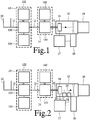
- Figure 1 schematically shows an apparatus for identifying biological material.
- an application to identification of micro-organisms will be described in the context of this apparatus, it should be appreciated that the apparatus is only one embodiment of an apparatus that performs MALDI mass spectroscopy on flying droplets. It should be understood that other biological material may be used instead of micro-organisms, such as cells (e.g. blood cells, peptides etc.).
- the apparatus comprises a sample receiver 10, conduits 11, a first mixing unit 12, a second mixing unit 14, a chamber 15, a piezo resonator 16, a control circuit 17, a pulse laser 18 and a mass spectrometer 19.
- Piezo resonator 16 may be of a type used in inkjet printers to form drops of ink.
- Conduits 11 connect sample receiver 10, first mixing unit 12, second mixing unit 14 and piezo resonator 16 in series.
- Control circuit 17 is coupled to piezo resonator 16 and pulse laser 18.
- Piezo resonator 16 is located in chamber 15. Conduit 11 from second mixing unit 14 discharges into an opening through piezo resonator 16. Pulse laser 18 is directed at a flight path of droplets launched from this opening through chamber 15. Mass spectrometer 19 is attached to chamber 15 and located to receive ionized fragments that result from absorption of radiation from pulse laser 18 by droplets in the flight path.
- a stream of liquid, containing sample material from sample receiver 10, diluent from first mixing unit 12 and matrix material from second mixing unit 14, is separated into sections that each result in a small liquid drop launched in flight through chamber 15.
- the matrix material in a liquid drop crystallizes around a micro-organism while the drop dries in flight, resulting in a dried particle.
- a laser pulse is fired at the dried particle from pulse laser 18. This results in ionization of material from the dried particle.
- the ionized material is analyzed in mass spectrometer 19.
- Drops with a diameter in a range of 1-100 micrometer may be used for example.
- drops having substantially a same uniform size in this range are used, which may be realized by breaking up the stream of liquid at regular distances, for example by applying a periodic disturbance of appropriate frequency on a stream of constant average flow rate.
- the drops are prepared for ionization. Because the preparation occurs in flight, micro-organisms with matrix material surrounding a micro-organism on all sides may be formed. No crystallization nuclei occur at the interface between drops and a target plate, as in the case of conventional MALDI-MS.
- the combination of the dilution rate and drop size is selected so that most drops with a microorganism contain no more than one microorganism. For example, a dilution level corresponding to a concentration of at most one micro-organism on average in the volume of a drop may be used.
- each measured mass spectrum of a particle from a drop with one micro-organism represents one micro-organism only.
- the use of drops means that the size of the sample that is ionized is determined by the drop size and the amount of dissolved and dispersed material inside the drop.
- the size of the sample is determined by the size of the laser spot on the target plate, which may be much larger than the size of drops, so that more material is ionized that can lead to an increased "noise"-level in the mass spectrum.
- a mix of different micro-organisms may be ionized.
- First mixing unit 12 serves as a dilution unit. It comprises a first mixer 120, a diluent reservoir 122 and a detector 124. Diluent reservoir 122 is coupled to first mixer 120 to supply diluent and first mixer 120 is configured to mix the diluent with sample material from sample receiver 10.
- Detector 124 may be an optical detector configured to detect light scattered from individual micro-organisms when the micro-organisms flow through a measurement beam, for example in a conduit through which liquid with the micro-organisms is circulated. From a count of micro-organisms that are detected on average per unit time interval, the density may be determined. In another embodiment an optical scattering intensity may be measured from liquid in first mixer 120 containing diluent and material from sample receiver 10.
- cytometers of this type are known per se.
- a known type of cytometer, or flow cytometer may be used.
- a cytometer may be a device that detects local fluctuations of biological material density corresponding to difference between the spatial concentration of material in individual micro-organisms against the background of neighboring liquid. For example, temporal fluctuations may be detected at a location through which a flow of liquid with the micro-organisms occurs, or spatial fluctuations may be detected by scanning a detection location.
- On optical detection may be used for example, using a device that provides for the detection of fluorescence or other optical properties focused in a small region with a size less than a maximum liquid volume per micro-organism.
- One or more detectors may be used that detect fluorescence at wavelengths at which material such as NADH fluoresces that is characteristic of micro-organisms. Other optical properties, such as scattering, diffraction etc. may also be used.
- Particle detector 124 is shown coupled to a control input of first mixer 120.
- the control mechanism is arranged to increase the amount of diluent added to the sample until the measured density has dropped to or below a predetermined density.
- a liquid circulation circuit may be used to circulate the diluted sample along a diluent injection point until the desired density has been achieved.
- a control computer (not shown) may be used to receive measurement data from density detector 124 and to generate mixer control signals based on this data.
- sample receiver 10 In operation a liquid sample containing micro-organisms is provided in sample receiver 10.
- a pump (not shown) pumps sample material to first mixing unit 12 through conduit 11.
- First mixer 120 adds diluent to the sample material. Water or ethanol may be used as diluent for example.
- Batch-wise processing may be used, wherein a batch of sample material is supplied to first mixing circuit 12, after which processing continues with that batch, without obtaining further material from sample receiver 10 until the batch has been processed and has left first mixing unit 12.
- a batch size in a range from 0.01 to 10 milli-liters may be used for example.
- a feedback loop is used to increase the dilution rate until the density observed by density detector 124 has dropped to a predetermined level.
- a feed forward solution may be used, wherein the initial density is measured and the resulting level is used to control the amount of added diluent to the predetermined level.
- the predetermined level is selected so that a majority of the drops will contain one micro-organism or less.
- the level may be set so that on average of less than one micro-organism per drop is achieved, or an average between four and one quarter micro-organism per drop. It should be noted that an overall count of micro-organisms in the liquid suffices, unspecific for the type of microorganism. Thus a reasonable number of drops with only one micro-organism of any type can be ensured.
- the actual level may be selected in combination with the size of the drops, which is controlled by the setting of parameters of droplet formation, using a relation between measurements from detector 124 and the concentration of micro-organisms.
- this level may be set experimentally during a calibration step, based on observations of the fraction of drops in which material from micro-organisms is observed by mass-spectroscopy, by adjusting the level until the fraction of drops containing one micro-organism is at a predetermined level of for example one tenth to half of the generated mass spectra.
- a dilution up to a dilution ratio between one to five sample to diluent may be used.
- the feedback in first mixing unit 14 serves to ensure that samples with different concentrations of micro-organisms do not result in large changes in efficiency, in terms of the number of useless droplets that contain no micro-organisms, or in a considerable number of droplets that contain more than one organism. If the concentration can be controlled beforehand, no feedback or density determination may be needed. Similarly, feedback or density determination may be omitted if it is known that the concentration is not so high that a risk of a considerable number of droplets with multiple organisms persists after a predetermined dilution, and a loss of efficiency is accepted. In this case a predetermined dilution rate may be used, or first mixing unit 12 may even be omitted.
- Second mixing unit 14 comprises a second mixer 140 and a matrix material reservoir 142.
- Matrix reservoir 142 is coupled to second mixer 140 to supply matrix material to second mixer 140 and second mixer 140 is configured to mix the matrix material with the diluted sample material from first mixing unit 12.
- liquid is moved from first mixing unit 12 to second mixing unit 14.
- second mixing unit 14 may be combined with first mixing unit 14.
- MALDI matrix material is added.
- MALDI matrix materials are known per se from the prior art. Matrix material may be used that is suitable to crystallize attached to micro-organisms and that has have an optical absorption band suitable for absorbing the laser pulses to ionize material from the micro-organisms. A wide range of suitable matrix materials is known. MALDI matrix materials that do not form crystals are also known.
- Second mixing unit 14 may be configured to add MALDI matrix material in an amount sufficient to provide a molar matrix to analyte ratio in the order of 100:1 to 10000:1.
- the liquid obtained from second mixing unit 14 is pumped to an opening through piezo resonator 16 as a continuous stream of liquid via conduit 11.
- a conduit 11 directly connecting second mixing unit 14 to piezo resonator is shown, it should be understood that a batch of liquid may be transported from second mixing unit 14 to a position at an input of conduit 11 by any other means.
- An intermediate reservoir (not shown) may be used at the input of conduit 11.
- a liquid pump (not shown) may be used to pump a stream liquid through conduit 11 to piezo resonator 16, or a pump may be used to put pressure on the liquid in second mixing unit 14 or an intermediate reservoir to which the liquid has been moved in order to force the stream of liquid to piezo resonator 16 through conduit 11.
- Conduit 11 may be so short that effectively a direct connection from second mixing unit 14 or the intermediate reservoir to the opening through piezo resonator 16 is formed.
- piezo resonator 16 comprises a frame, a membrane with an orifice with an opening of twenty micrometer at which the flow of liquid is directed and piezo-electric material coupled between the membrane and the frame. Preferably an opening of at least ten micrometer is used.
- the piezo-electric material is located to make the orifice move back and forth in the direction of the liquid flow. Electrodes are provided on the piezo-electric material to drive the motion.
- control circuit 17 applies a high frequency electric excitation to the electrodes.
- a frequency in a range of 1 kHz to 1MHz may be used for example.
- the high frequency electric voltage causes periodic movement of the opening in the direction of the liquid flow, which cause the liquid stream to break up into parts, resulting in droplets.
- a series of droplets is launched along a flight path through chamber 15.
- a constant setting of the excitation frequency of piezo resonator 16 is used, so that drops of the same size are produced.
- Techniques to control drop size are known per se from ink jet printing technology.
- an atmosphere with a low pressure is maintained, for example in the range of a thousandth of a millibar to a few millibar.
- the atmosphere may consist of any gas. In an example normal air is used.
- the length of the flight path from piezo resonator 16 to the point of ionization is preferably at least so along that the time needed to traverse the flight path, given the speed of the drops, is sufficient to put the matrix in place, e.g. by crystallization.
- one or more intermediate nozzle skimmers may be used along the flight path to reduce the gas pressure until a level suitable for mass-spectroscopy is reached. In an embodiment mass spectroscopy is performed at pressures near 10 -6 millibar, or more generally below 10 -5 millibar.
- drops of a size of a few micrometer e.g. in the range between one and ten micrometer
- the drops dry sufficiently to realize matrix formation (e.g. crystallization) within milliseconds or even within microseconds.
- matrix formation e.g. crystallization
- a gas flow source (not shown) may be provided adjacent to piezo resonator 16 to create a gas jet along the flight path. Such a jet may help to reduce the chance that consecutive drops agglomerate.
- Control circuit 17 controls pulse laser 18 to generate pulses in synchronism with oscillations of piezo resonator 16, with a relative phase so that pulses from pulse laser 18 will arrive in the flight path at the time points when droplets from piezo resonator 16 pass through the laser beam. This results in ionization of the particles from the droplets.
- Mass spectrometer 19 analyses the mass spectrum of the emerging particles.
- the synchronization of laser pulses with oscillations of piezo resonator 16 may be realized by synchronizing the laser pulses to the excitation signal of piezo resonator 16.
- a droplet detector (not shown) may be used to detect droplets along the flight path in chamber 15 and pulsed laser 18 may be triggered by signals from such a detector. This detector may also be configured to measure droplet speed, to predict a time of arrival of each droplet. Alternatively, a predetermined speed may be assumed, which can be determined experimentally.
- Mass spectra may be collected in control circuit 17, or in a measurement computer, and compared to reference spectra or parts of reference spectra or lists of biomarkers for known micro-organisms to identify the type of the micro-organisms in the respective drops.
- a comparison with a small number of reference spectra may suffice.
- a count of identified micro-organisms may be computed, to determine a concentration of the identified micro-organisms by comparing the count with an overall count of drops, or with a count of drops that contain a micro-organism or cell of a reference type.
- a comparison with a larger number of reference spectrograms may be performed to identify a range of types of micro-organisms or cell types in the sample.
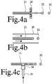
- Figure 2 shows an embodiment that uses prescreening of droplets.
- a further laser 20 and a fluorescence detector 22 have been added.
- Further laser 20 has a wavelength selected to excite fluorescence of micro-organisms in the droplets. A wavelength of 266 nm may be used for example.
- Further laser 20 is directed at a part of the flight path 24 of droplets before they reach the point of ionization. A continuous wave laser may be used, or a pulsed laser synchronized to drop formation.
- Fluorescence detector 22 is similarly directed at the flight path 24, to capture fluorescence from a flying drop after irradiation by further laser 20.
- Fluorescence detector 22 is coupled to control circuit 17, which is configured to cause pulsed laser to fire conditionally, only at drops wherein fluorescence indicative of the presence of a micro-organism has been detected.
- further laser 20 may be used to trigger firing, that is, to select the time point of firing.
- one or more lasers may be used to trigger firing using time points and/or speeds of drops detected with the one or more lasers. This may be done independent of whether a further laser 20 is used.
- fluorescence may be detected in conduit 11, before separation of the liquid into drops at piezo resonator 16.
- further laser and fluorescence detector are directed at conduit 11 and control circuit 17 may determine the drop in which the micro-organism will be isolated from the time of detection, the flow speed to piezo resonator 16 and the excitation signal of piezo resonator 16. Detection of fluorescence in conduit 11 may help to prevent that matrix crystallization obstructs detection of fluorescence from the micro-organisms.
- Figure 3 shows an embodiment wherein the apparatus comprises an ultrasound source 30 directed at sample receiver 10, or the conduit 11 between sample receiver 10 and first mixing unit 12 and configured to separate clusters of micro-organisms into individual micro-organisms.
- ultrasound source 30 may be used to separate micro-organisms from a sample carrier on which the micro-organisms have been collected, such as a cotton swab or a piece of filtration paper.
- Separation of clusters may be used to reduce the number of droplets in which more than one micro-organism is present at a time.
- ultrasound source 30 is directed at sample receiver 10
- one or more ultrasound sources 30 may be directed at any position between sample receiver 10 and piezo resonator 16, for separating clusters. Separation of clusters before first mixing unit 12 has the advantage that a more reliable density determination and more homogeneous dilution may be obtained.
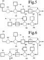
- FIG 4a schematically shows more detail of a separator with a piezo resonator 16.
- the conduit 11 ends at the opening through piezo resonator 16, which periodically constricts to launch drops.
- a piezo resonator 16 is used to separate the stream of liquid into drops
- other droplet forming techniques may be used.
- a gas dynamic nozzle may be used, which is known per se, wherein conduit 11 opens into a gas flow that acts to separate the stream of liquid into droplets when or after the stream is injected in the gas flow.
- Figure 4b shows an example of a configuration may be used wherein the end of conduit 11 exhausts in a larger conduit 50 wherein the gas flow is supplied.
- drops may be formed after injecting the stream of liquid into a gaseous environment.
- gas and liquid flow rates and the opening size are set so a narrow range of droplet sizes is obtained, as this increases efficiency and simplifies control needed to ensure that pulsed laser 18 fires at the time needed to hit a droplet.
- a drop separation mechanism similar to dripping from a tap may be used, wherein a stream of liquid is forced through a conduit to an opening of the conduit and drops are torn off into flight from the opening. Gravity, or a gas flow past the opening may be used to tear of drops from the opening.
- drop size may be controlled by means of selection of flow rate of the stream of liquid, diameter and/or shape of the opening and gas flow speed.
- a gas inlet 54 into conduit 11 as shown in figure 4c may be used to inject gas bubbles at regularly spaced distances into the stream of liquid through conduit 11.
- a valve 56 in gas inlet 54 may be used to form the bubbles. The bubbles separate the stream into sections before the stream reaches the opening of conduit 11, so that each section will result in a respective drop when the stream is forced out of the opening of conduit 11.
- the apparatus provides for a process of identifying micro-organisms wherein a stream of liquid containing micro-organisms and matrix material.
- the liquid stream is broken up into droplets, preferably into monodisperse droplets.
- the droplets are supplied in flight along a flight path. These droplets are dried in the vacuum while in flight.
- the resulting dried particles are ionized to obtain a mass spectrogram.
- the particles are analyzed in flight.
- the liquid is diluted to a dilution level at which a majority of the drops with microorganism contain only one micro-organism.
- a transportable sample holder may be used, which may be transported to a diluent mixing unit, a matrix material mixing unit and a droplet forming station.
- Diluent mixing and matrix material mixing may be performed in a single mixing unit 40, as shown in figure 4 , with a mixing stage 42 for mixing the sample both with diluent and matrix material, simultaneously or in different time intervals.
- Part of the transport may be performed in conduits and another part may be performed with a transport units.
- the sequence of dilution and addition of matrix material may be changed, or any mixing step may be split in a plurality of mixing steps.
- the technique can be use to identify other types of biological material, such as cells, for example blood cells or specific types of such cells.
- the sample may contain a mix of various materials and a plurality of types of material may be identified from the sample, by combining results obtained from mass-spectrograms of different drops.
- a sample of biological material may be taken from a patient, for example from saliva, or from any mucous membrane or a blood sample or a urine sample or combinations thereof, and the sample may be processed as described.
- the resulting identifications of micro-organisms in drops from their mass spectrograms, or a count of drops that contain a micro-organism with a mass spectrogram that matches the reference mass spectrogram of a harmful micro-organism such as a Staphylococcus Aureus with a specific antibiotic resistance may be used to decide whether or not to accept the patient for normal treatment. Patients with harmful micro-organisms may be redirected for special treatment.
- outbreaks of infections with harmful micro-organisms may be monitored by taking samples from a plurality of patients and processing the samples as described.
- samples from different patients may be mixed, for example if identification of harmful micro-organisms in a group of people is needed, e.g. in a hospital ward, without need to single out individual patients.
- a sample of biological material may be taken from a patient, and the sample may be processed as described to detect infection with specific micro-organisms.
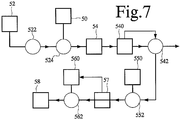
- Figure 5 shows an identification apparatus comprising a sample reservoir 50, a first carrier liquid reservoir 520, a pump 522, a first mixing stage 524, a Flow Field-Flow fractionator 54, a size detector 540, a three way valve 542, a matrix reservoir 550, a second mixing stage 552, a second carrier liquid reservoir 560, a third mixing stage 562, a flow cytometer 57 and a drop former 58.
- Pump 522, first mixing stage 524, Flow Field-Flow fractionator 54, three way valve 542, second mixing stage 552, third mixing stage 562 and drop former 58 are coupled in series along a liquid flow channel.
- First carrier liquid reservoir 520 feeds into an input of pump 522.
- Sample reservoir 50 feeds into an input of first mixing stage 524.
- Size detector 540 is coupled to a part of the liquid flow channel downstream from Flow Field-Flow fractionator 54 and upstream of three way valve 542.
- Matrix reservoir 550 feeds into an input of second mixing stage 552.
- Second carrier liquid reservoir 560 feeds into an input of third mixing stage 562.
- Flow cytometer 57 is coupled to a part of the liquid flow channel downstream from third mixing stage 562 and upstream of drop former 58.
- the apparatus may contain buffers for storing variable amounts of liquids at one or more positions along the liquid flow channel, between three way valve 542 and second mixing stage 552 for example.
- the buffers may be used to reduce variations in flow rate.
- pump 522 pumps carrier liquid from first carrier liquid reservoir 520 through the flow channel.
- Water may be used as carrier liquid for example, with an addition of ammonium acetate.
- First mixing stage 524 mixes a pulsed quantity of sample liquid into the stream of carrier liquid, during a pulse time interval.
- Flow Field-Flow fractionator 54 fractionates the stream into temporally successive fractions according to particle size.
- Size detector 540 detector detects a size of the particles as a function of time and it controls three way valve 542 to pass the flow to second mixing stage 552 or a waste output, dependent on the detected size.
- Second mixing stage 552 mixes MALDI matrix material from matrix reservoir 550 into the stream. Continuous mixing may be used.
- Third mixing stage 562 mixes additional carrier liquid into the stream.
- Flow cytometer 57 measures the density of micro-organisms in the stream.
- the mixing rate of third mixing stage 562 is controlled dependent on the measured density.
- Drop former 58 separates the stream into successive parts of the stream and launches drops, each formed from a respective part.
- the flow channel is designed so that the stream flows from second mixing stage 552 to drop former 58 without any substantial axial rearrangement. That is, large reservoirs where the liquid can accumulated and mix are avoided in the flow-channel. As a result, that parts into which drop former 58 separates the liquid correspond to successive sections of the stream already after second mixing stage 552, or at least after third mixing stage 562.
- the dilution at third mixing stage 562 is performed by mixing carrier liquid into the flowing stream.
- a feedback loop may be used to control third mixing stage 562, the feedback loop being designed to change the mixing rate upward or downward according to whether the measured density "C" is above or below a preset target value.
- control of third mixing stage 562 may cease to be dependent of the density.
- any other fractionating device may be used that fractionates the stream with a pulse of sample liquid into a stream with gradually changing particle size. This has the advantage that it reduces the amount of relatively small sized material from the sample that could obstruct identification of micro-organisms when present in the drops. Furthermore, it has the advantage that the rate of mixing in third mixing stage 562 can be adapted in time to provide for micro-organism density differences between different fractions of micro-organisms. Thus drops with a single micro-organism can be more easily realized for each of the fractions. When fractions with widely different density are simultaneously present this may be difficult.
- a conventional Flow Field-Flow fractionator 54 may be used.
- Such a column is described for example in the article by Hookeun Lee et al., cited in the preceding. Briefly, such an apparatus uses a thin ribbon like open channel through which a stream of carrier liquid with sample material flows. Different flow speeds arise as a function of position in the channel transverse to the flow direction. By means of an external field different transverse density distributions are realized for different fractions of particles.
- An external field such as an electric field, an imposed temperature gradient, gravity etc, may used. The density distribution arises from a balance between the effect of the field and diffusion that counteracts the density gradient. As a result different fractions will emerge at the output of the Flow Field-Flow fractionator 54 separated by time, leaving micro-organisms intact.
- Size detector 540 serves to detect the size of the particles of the emerging fractions. Size detector 540 may be omitted when a tightly controlled Flow Field-Flow fractionation process is used. In this case three way valve 542 may be controlled by a timer for example, that defines time intervals for passing liquid towards second mixing stage 552 at predetermined delays after the pulses of sample material. Size detector 540 may be configured to measure light scattering as a measure of size, but other techniques such as conductivity measurements or detection of fluorescence may be used.
- Flow cytometer 57 may comprise a fluorescence detector configured to detect temporal peaks in fluorescence in passing liquid that are due to micro-organisms. Fluorescence at a wavelength corresponding to NADH may be used for example. A count of such peaks per time unit may be used as a density signal to control third mixing stage 562.
- detections of individual microorganisms from flow cytometer 57 may be used to enable laser firing of the pulse laser (not shown), firing at a drop being disabled when flow cytometer 57 does not detect a micro-organism in the part of the liquid stream from which the drop will be formed.
- control of firing may be used to maintain efficient mass spectroscopy.
- Figure 6 shows an apparatus with an additional three way valve 60 between flow cytometer 57 and drop former 58, with a control input coupled to flow cytometer 57.
- detections of individual microorganisms are used to control additional three way valve 60, making it pass liquid to drop former 58 when a microorganism is detected and to a waste output otherwise. In this way the number of useless drops is minimized.
- control of waste output may be used to maintain efficient mass spectroscopy.
- "on demand" control of drop former 58 is used, to trigger drop forming when the liquid is not fed to the waste output.
- Figure 7 shows an apparatus wherein flow cytometer 57 is located upstream of third mixing stage 562.
- a feed forward control is realized according to a predetermined relation between detected micro-organism density and mixing rate.
- F add is the mixed in flow rate from second carrier liquid reservoir 560
- N org is the incoming density of detected microorganisms per unit time
- V drop is the volume of the liquid part from which a drop is formed
- Density may be determined by counting detected micro-organisms or from the time distance between successive detections.
- third mixing stage 562 of the embodiment of figure 7 may be controlled dependent on detection of individual microorganisms, the mixing rate being controlled dependent on the time distance between successive detections of organisms, increasing the amount of added carrier liquid when the time distance decreases.
- the feed forward solution of figure 7 has the advantage that it makes it possible to provide for detection from smaller samples.
- the feed forward solution may be combined with use of additional three way valve 60 (not shown) or enabling of firing.
- the control may be statistical, preventing firing when only a low percentage of drops contains micro-organisms.
- flow cytometer 57 is located between second and third mixing stage 552, 562. It should be appreciated that flow cytometer 57 may also be located upstream of second mixing stage 562. In this case the density is measured before the addition of MALDI matrix material.
- second mixing stage 562 When second mixing stage 562 is designed to add MALDI matrix material at a known rate, the density of micro-organisms in the stream before second mixing stage 562 can be translated into a density after this stage. For better control a flow cytometer 57 after second mixing stage 562 is preferred.
- the density measurement from cytomer 57 of figure 7 may be used to control laser firing and/or an additional three way valve (not shown).
- the additional three way valve may be located at a similar position as three way valve 60 in figure 6 , or between flow cytomer 57 and third mixing stage 552.
- size detector 54 may be replaced by a cytometer, which controls three way valve 542 to pass liquid to second mixing stage 552 upon detection of at least a threshold density of microorganisms. In this case this cytometer may also be used to control dilution by third mixing stage 562.
- a single cytometer has been shown both multiple purposes, it should be appreciated that instead a plurality of cytometers may be used, each for implementing a respective one or groups of these purposes.
- a flow cytometer upstream of drop former 58 may be used to control firing of pulse laser 18 even without measures to control dilution. This may be used for example when it is known that the density of micro-organisms will never be too high.
- a flow cytometer upstream of drop former 58 may be used to control a three way valve to supply liquid to drop former 58 selectively upon the detection of microorganisms or detection that a density of micro-organisms execeeds a threshold value. This may be done even without measures to control dilution.
- a combination of control of laser firing and a three way valve may be used.
- an apparatus for identifying biological material in a sample comprising
- valves Although use of three way valves has been described to realize a flow path selector, to switch between passing liquid for further processing and wasting the liquid, it should be appreciated that other types of valve may be used for this, such as manifolds.
- a plurality of branches with Flow Field-Flow fractionators 54 may be used in parallel to handle different samples.
- Each branch may contain the components corresponding to those up to and including three way value 542 for example.
- a liquid manifold may be used to connect these branches to the input of second mixing stage 552 successively.
- a method of identifying biological material in a sample comprising preparing a liquid comprising the sample and a MALDI matrix material; generating a continuous stream of the liquid; separating the stream into successive parts to form flying drops; ionizing material from the drops while in flight; and measuring mass spectra from the ionized material.
- the biological material comprises micro-organisms.
- the method may comprise diluting the sample or the liquid to a dilution level corresponding to a concentration of less than one micro-organism on average in a volume of individual ones of the parts.
- the dilution level may be measured and the dilution may be controlled to proceed until the liquid has been diluted to said concentration.
- a cluster separation step may be applied to the sample or the liquid to separate clusters of micro-organisms into individual micro-organisms before the separating step.
- the liquid may be separated into parts of substantially equal volume, for example by separating the successive parts at regular intervals in said stream.
- the successive parts of liquid may be launched into flight during or after separating them from the stream.
- the stream may be launched into flight and the stream may be separated into the successive parts while in the stream is in flight.
- the drops may be dried in flight, at least to a drying level where crystals of the matrix material are formed in flight, prior to the ionizing step.
- a gas jet may be applied along at least part of a trajectory of the drops in flight.
- the drops may be screened based on fluorescence before said ionizing, and ionizing only drops with parts of the liquid that has been detected to produce at least a predetermined fluorescence intensity.
- An apparatus for identifying biological material in a sample, the apparatus comprising a mixer configured to prepare a liquid wherein the sample and a crystal forming matrix material are mixed; a stream generator configured to supply a continuous stream of the liquid; a liquid portion separator configured to separate the stream into parts and to supply drops formed from said parts in flight along a flight path; a radiation source directed at the flight path and configured to supply radiation for ionizing material from the drops; and a mass spectrometer configured to obtain mass spectrograms of the ionized material from individual ones of the drops.
Landscapes
- Chemical & Material Sciences (AREA)
- Physics & Mathematics (AREA)
- Analytical Chemistry (AREA)
- Health & Medical Sciences (AREA)
- Life Sciences & Earth Sciences (AREA)
- Engineering & Computer Science (AREA)
- Pathology (AREA)
- Biochemistry (AREA)
- General Health & Medical Sciences (AREA)
- General Physics & Mathematics (AREA)
- Immunology (AREA)
- Optics & Photonics (AREA)
- Biomedical Technology (AREA)
- Plasma & Fusion (AREA)
- Dispersion Chemistry (AREA)
- Biophysics (AREA)
- Hematology (AREA)
- Molecular Biology (AREA)
- Urology & Nephrology (AREA)
- Food Science & Technology (AREA)
- Medicinal Chemistry (AREA)
- Other Investigation Or Analysis Of Materials By Electrical Means (AREA)
- Apparatus Associated With Microorganisms And Enzymes (AREA)
- Electron Tubes For Measurement (AREA)
Description
- The invention relates to a method of identifying biological material that comprises microorganisms in a sample in accordance with the preamble of claim 1. Such a method is disclosed in an article titled "Matrix-assisted laser deporption/ionization aerosol time of flight mass spectroscopy for the analysis of bioaerosols: development of a fast detector for airborne biological pathogens" by A.L. van Wuijckhuijse et al and published in the Journal of Aerosol Science Vol 36 pages 677-697 (EPO reference XP004936536). This document describes the use of a nebulizer to nebulize solutions that were produced by diluting mono-culture bacterial samples to predetermined values. The nebulization mentioned in this document does not guarantee drops of a uniform size. As a result the number of bacteria per drop may vary, but this did not matter as only one species of bacteria was used. Moreover, the nebulization method of this document requires that a large sample volume is available, even if distributed over small drops.
- It is known to use mass- spectroscopy for the identification of biological material such as micro-organisms (e.g. bacteria, virusses), cells, peptides etc.
- MALDI-MS (Matrix Assisted Laser Desorption-Ionization-Mass Spectroscopy), for example, involves laser ionization of sample material containing micro-organisms and mass spectroscopic analysis of the ionized particles. In MALDI-MS the micro-organisms are prepared for ionization by providing a mixture of micro-organisms and matrix material on a target plate. While the mixture dries, the matrix material attaches to the micro-organisms, which enables soft ionization with relatively low energy that preserves large molecular fragments for the analysis constituents of the micro-organisms. Laser shots are fired at selected target locations on the target plate in order to ionize material from these target locations. For each target location a mass spectroscopic analysis of the resulting is performed.
- MALDI-MS has been found to be very suitable for laboratory analysis, but several problems remain. For samples with an inhomogeneous mix of micro-organisms there is a serious risk that a single laser shot ionizes material from a mix of micro-organisms of different species, which complicates the identification of individual species. Even if an isolated single microorganisms could be found on the target plate, it would not be possible to detect it in the noise of all material ionized by a laser shot. In MALDI-MS these problems are overcome by using an initial breeding step when the original sample, taken for example from patient in vivo, contains an inhomogeneous mix of micro-organisms. Breeding may be used to ensure that a substantial number of micro-organisms of mainly one strain are produced within a single laser shot. However, breeding may take over a day. As a result, practical MALDI-MS is not suitable if a short turn around time is needed between taking an in vivo sample and providing an analysis result. This limits its applicability.
- For example, in an example before transferring an incoming patient to an environment where the MRSA bacteria could do harm, it would be desirable to obtain a sample from the patient, and identify MRSA bacteria among the many micro-organisms present in the sample. To be of practical use, a result of such a measurement should preferably be available within a few hours at most. The need to breed micro-organisms prevents practical use of conventional MALDI-MS for this purpose.
- From
WO02052246 - From
US patent application 2005/0230615 a MALDI-IM (Ion Mobility) measurement technique is known wherein drops are formed with a Vibrating Orifice Aerosol Generator. Nothing is disclosed about micro- organisms in the drops. If the drops would contain micro-organisms, use of MALDI-IM would make it difficult if not impossible to identify these microorganisms. - The use of Flow Field- Flow Fractionation (FFFF) in the preparation of a target plate for MALDI-MS is known from an article by Hookeun Lee et al, titled "Analysis of Whole Bacterial Cells by Flow- Field Flow Fractionation and Matrix-Assisted Laser Desorption/Ionization Time-of- Flight Mass Spectroscopy" and published in Anal. Chem. 2003, 75, 2746-2752. This document shows that FFFF can be used to separate intact bacterial cells to increase cell density for MALDI-MS, when a target plate is used.
- Among others it is an object of the invention to provide for a method and apparatus for identifying biological material that can provide results quickly based on a liquid sample with a mix of different types of microorganisms, such as bacteria, fungi and viruses.
- A method of identifying biological material that comprises microorganisms in a sample in accordance with claim 1 is provided.
- Herein flying drops of liquid are formed, by separating a stream of liquid comprising biological material from a sample and MALDI matrix material, for example a crystal forming matrix material, into successive parts of the stream. An active drop former may be used for example, with a piezoelectric element. Ionization and mass spectroscopy is performed on the drops while in flight. In this way the need for a target plate and its disadvantages can be eliminated, while a high efficiency is realized. The drops may dry in flight so that the dried drops are dried particles when they are ionized. As used herein, the term "drop" includes the dried particles formed by drying the drops. Preferably, mass spectra are measured each for the material from a respective one of the drops. The sample or the liquid is diluted to a dilution level corresponding to a concentration in which the density C of micro-organisms satisfies C∗V<1, where V is a volume of said parts of the liquid. Thus less than one microorganism or cell will occur on average in a drop volume in an individual drop. Thus, it may be ensured that a considerable number of measurements of drops with a single micro-organism or cell per drop can be obtained. As a result, mass spectra for individual micro-organisms and/or cells can be obtained.
- In an embodiment the dilution level may be adapted to the concentration of cells and/or micro-organisms in the sample. A density detector may be used to measure the concentration, for example by counting detected micro-organisms, and the measured concentration may be used to control dilution. The density detector may comprise a (flow) cytometer located to detect the density in the stream, for example by counting micro-organisms in the stream, or in a precursor stream that flows into the stream when the MALDI matrix is added to the precursor stream. In an embodiment, the stream flows to the drop former without any substantial axial rearrangement after the point where the stream with sample and matrix material is generated. That is, that parts into which the liquid is separated correspond to successive sections of the stream already once the matrix material has been added, or at least after dilution. In this way the probability of drops with multiple micro-organisms is reduced. This is improved by measuring the density in this stream with a cytometer and controlling the dilution based on this measurement. In an embodiment the dilution may be performed by mixing carrier liquid into the stream downstream from the generation of the stream. This also reduces the probability of drops with multiple micro-organisms.
- A method of monitoring for outbreaks of an infection with a predetermined micro-organism in a hospital in accordance with claim 13 is provided.
- Furthermore an apparatus for identifying biological material in a sample in accordance with
claim 14 is provided. - The liquid portion separator may be a drop former, comprising a piezo-electric resonator for example.
- In another embodiment the liquid portion separator of the apparatus comprises a gas stream supply outlet and a conduit for supplying a stream of the liquid into the outlet configured to form a gas dynamic nozzle.
- In another embodiment the apparatus comprises a diluting unit configured to add diluent to the sample or the liquid to a dilution level corresponding to a concentration of less than one micro-organism on average in a drop volume of individual ones of the drops. Alternatively, a concentration may be used at which a majority of drops contains at most one micro-organism from the sample. In a further embodiment the dilution unit comprises a density detector configured to detect a density of the sample or the liquid with the sample and to control dilution to said level dependent on the detected density.
- In an embodiment, the liquid portion separator may be configured to launch the drops directly into the vacuum space in which the ionization is performed.
- In another embodiment the apparatus comprises a control unit configured to synchronize drop formation and pulse generation from the radiation source.
- These and other objects and advantageous aspects will become apparent from a description of exemplary embodiments.
- Figure 1
- shows an apparatus for identifying micro-organisms
- Figure 2
- shows an identification apparatus with fluorescent screening
- Figure 3
- shows an identification apparatus with an ultrasonic separator
- Figure 4
- shows an further identification apparatus
- Figures 4a-c
- show examples of liquid stream separators
- Figure 5-7
- show embodiments of an identification apparatus Detail
-
Figure 1 schematically shows an apparatus for identifying biological material. Although an application to identification of micro-organisms will be described in the context of this apparatus, it should be appreciated that the apparatus is only one embodiment of an apparatus that performs MALDI mass spectroscopy on flying droplets. It should be understood that other biological material may be used instead of micro-organisms, such as cells (e.g. blood cells, peptides etc.). - The apparatus comprises a
sample receiver 10,conduits 11, afirst mixing unit 12, asecond mixing unit 14, achamber 15, apiezo resonator 16, acontrol circuit 17, apulse laser 18 and amass spectrometer 19.Piezo resonator 16 may be of a type used in inkjet printers to form drops of ink.Conduits 11connect sample receiver 10, first mixingunit 12,second mixing unit 14 andpiezo resonator 16 in series.Control circuit 17 is coupled topiezo resonator 16 andpulse laser 18. -
Piezo resonator 16 is located inchamber 15.Conduit 11 from second mixingunit 14 discharges into an opening throughpiezo resonator 16.Pulse laser 18 is directed at a flight path of droplets launched from this opening throughchamber 15.Mass spectrometer 19 is attached tochamber 15 and located to receive ionized fragments that result from absorption of radiation frompulse laser 18 by droplets in the flight path. - In operation a stream of liquid, containing sample material from
sample receiver 10, diluent from first mixingunit 12 and matrix material fromsecond mixing unit 14, is separated into sections that each result in a small liquid drop launched in flight throughchamber 15. During flight throughchamber 15 the matrix material in a liquid drop crystallizes around a micro-organism while the drop dries in flight, resulting in a dried particle. Subsequently, a laser pulse is fired at the dried particle frompulse laser 18. This results in ionization of material from the dried particle. The ionized material is analyzed inmass spectrometer 19. - Drops with a diameter in a range of 1-100 micrometer may be used for example. Preferably, drops having substantially a same uniform size in this range are used, which may be realized by breaking up the stream of liquid at regular distances, for example by applying a periodic disturbance of appropriate frequency on a stream of constant average flow rate.
- Because of the small size of the drops, only little time during flight is needed the drops are prepared for ionization. Because the preparation occurs in flight, micro-organisms with matrix material surrounding a micro-organism on all sides may be formed. No crystallization nuclei occur at the interface between drops and a target plate, as in the case of conventional MALDI-MS. Preferably, the combination of the dilution rate and drop size is selected so that most drops with a microorganism contain no more than one microorganism. For example, a dilution level corresponding to a concentration of at most one micro-organism on average in the volume of a drop may be used.
- Because
pulsed laser 18 is fired at one dried particle at a time, each measured mass spectrum of a particle from a drop with one micro-organism represents one micro-organism only. Moreover, the use of drops means that the size of the sample that is ionized is determined by the drop size and the amount of dissolved and dispersed material inside the drop. This should be contrasted with conventional MALDI-MS, wherein the size of the sample is determined by the size of the laser spot on the target plate, which may be much larger than the size of drops, so that more material is ionized that can lead to an increased "noise"-level in the mass spectrum. Also, a mix of different micro-organisms may be ionized. - An experiment was conducted to show that individual Staphylococcus Aureus with and without penicillin resistance could be distinguished. In this experiment aerosolization of liquid containing sample material, diluent and matrix material was used. Individual particles (vacuum dried droplets) were ionized with a pulsed laser and a mass spectrum of the ionized material was obtained. It was found that particles with Staphylococcus Aureus with penicillin resistance and particles with Staphylococcus Aureus without penicillin resistance could be distinguished based upon their mass spectra.
- First mixing
unit 12 serves as a dilution unit. It comprises afirst mixer 120, adiluent reservoir 122 and adetector 124.Diluent reservoir 122 is coupled tofirst mixer 120 to supply diluent andfirst mixer 120 is configured to mix the diluent with sample material fromsample receiver 10.Detector 124 may be an optical detector configured to detect light scattered from individual micro-organisms when the micro-organisms flow through a measurement beam, for example in a conduit through which liquid with the micro-organisms is circulated. From a count of micro-organisms that are detected on average per unit time interval, the density may be determined. In another embodiment an optical scattering intensity may be measured from liquid infirst mixer 120 containing diluent and material fromsample receiver 10. - Detectors of this type are known per se. A known type of cytometer, or flow cytometer may be used. As is known per se, a cytometer may be a device that detects local fluctuations of biological material density corresponding to difference between the spatial concentration of material in individual micro-organisms against the background of neighboring liquid. For example, temporal fluctuations may be detected at a location through which a flow of liquid with the micro-organisms occurs, or spatial fluctuations may be detected by scanning a detection location. On optical detection may be used for example, using a device that provides for the detection of fluorescence or other optical properties focused in a small region with a size less than a maximum liquid volume per micro-organism. One or more detectors may be used that detect fluorescence at wavelengths at which material such as NADH fluoresces that is characteristic of micro-organisms. Other optical properties, such as scattering, diffraction etc. may also be used.
-
Particle detector 124 is shown coupled to a control input offirst mixer 120. The control mechanism is arranged to increase the amount of diluent added to the sample until the measured density has dropped to or below a predetermined density. A liquid circulation circuit may be used to circulate the diluted sample along a diluent injection point until the desired density has been achieved. In practice, a control computer (not shown) may be used to receive measurement data fromdensity detector 124 and to generate mixer control signals based on this data. - In operation a liquid sample containing micro-organisms is provided in
sample receiver 10. A pump (not shown) pumps sample material tofirst mixing unit 12 throughconduit 11.First mixer 120 adds diluent to the sample material. Water or ethanol may be used as diluent for example. Batch-wise processing may be used, wherein a batch of sample material is supplied tofirst mixing circuit 12, after which processing continues with that batch, without obtaining further material fromsample receiver 10 until the batch has been processed and has left first mixingunit 12. A batch size in a range from 0.01 to 10 milli-liters may be used for example. - A feedback loop is used to increase the dilution rate until the density observed by
density detector 124 has dropped to a predetermined level. Instead of feedback, a feed forward solution may be used, wherein the initial density is measured and the resulting level is used to control the amount of added diluent to the predetermined level. In an embodiment the predetermined level is selected so that a majority of the drops will contain one micro-organism or less. The level may be set so that on average of less than one micro-organism per drop is achieved, or an average between four and one quarter micro-organism per drop. It should be noted that an overall count of micro-organisms in the liquid suffices, unspecific for the type of microorganism. Thus a reasonable number of drops with only one micro-organism of any type can be ensured. - The actual level may be selected in combination with the size of the drops, which is controlled by the setting of parameters of droplet formation, using a relation between measurements from
detector 124 and the concentration of micro-organisms. In one embodiment, this level may be set experimentally during a calibration step, based on observations of the fraction of drops in which material from micro-organisms is observed by mass-spectroscopy, by adjusting the level until the fraction of drops containing one micro-organism is at a predetermined level of for example one tenth to half of the generated mass spectra. In one example a dilution up to a dilution ratio between one to five sample to diluent may be used. - It should be noted that the feedback in
first mixing unit 14 serves to ensure that samples with different concentrations of micro-organisms do not result in large changes in efficiency, in terms of the number of useless droplets that contain no micro-organisms, or in a considerable number of droplets that contain more than one organism. If the concentration can be controlled beforehand, no feedback or density determination may be needed. Similarly, feedback or density determination may be omitted if it is known that the concentration is not so high that a risk of a considerable number of droplets with multiple organisms persists after a predetermined dilution, and a loss of efficiency is accepted. In this case a predetermined dilution rate may be used, or first mixingunit 12 may even be omitted. -
Second mixing unit 14 comprises asecond mixer 140 and amatrix material reservoir 142.Matrix reservoir 142 is coupled tosecond mixer 140 to supply matrix material tosecond mixer 140 andsecond mixer 140 is configured to mix the matrix material with the diluted sample material from first mixingunit 12. - In operation, liquid is moved from first mixing
unit 12 tosecond mixing unit 14. Although aconduit 11 has been shown for this purpose, it should be understood that a batch op liquid may be moved tosecond mixing unit 14 in any way. In another embodiment,second mixing unit 14 may be combined withfirst mixing unit 14. Insecond mixing unit 14 MALDI matrix material is added. MALDI matrix materials are known per se from the prior art. Matrix material may be used that is suitable to crystallize attached to micro-organisms and that has have an optical absorption band suitable for absorbing the laser pulses to ionize material from the micro-organisms. A wide range of suitable matrix materials is known. MALDI matrix materials that do not form crystals are also known. MALDI matrix material directed at specific types of organism or specific organic material may be used, but alternatively MALDI matrix material applicable to a wider range of organism and/or organic materials may be used.Second mixing unit 14 may be configured to add MALDI matrix material in an amount sufficient to provide a molar matrix to analyte ratio in the order of 100:1 to 10000:1. - The liquid obtained from
second mixing unit 14 is pumped to an opening throughpiezo resonator 16 as a continuous stream of liquid viaconduit 11. Although aconduit 11 directly connectingsecond mixing unit 14 to piezo resonator is shown, it should be understood that a batch of liquid may be transported fromsecond mixing unit 14 to a position at an input ofconduit 11 by any other means. An intermediate reservoir (not shown) may be used at the input ofconduit 11. A liquid pump (not shown) may be used to pump a stream liquid throughconduit 11 topiezo resonator 16, or a pump may be used to put pressure on the liquid insecond mixing unit 14 or an intermediate reservoir to which the liquid has been moved in order to force the stream of liquid topiezo resonator 16 throughconduit 11.Conduit 11 may be so short that effectively a direct connection fromsecond mixing unit 14 or the intermediate reservoir to the opening throughpiezo resonator 16 is formed. - In an embodiment
piezo resonator 16 comprises a frame, a membrane with an orifice with an opening of twenty micrometer at which the flow of liquid is directed and piezo-electric material coupled between the membrane and the frame. Preferably an opening of at least ten micrometer is used. The piezo-electric material is located to make the orifice move back and forth in the direction of the liquid flow. Electrodes are provided on the piezo-electric material to drive the motion. - In
operation control circuit 17 applies a high frequency electric excitation to the electrodes. A frequency in a range of 1 kHz to 1MHz may be used for example. The high frequency electric voltage causes periodic movement of the opening in the direction of the liquid flow, which cause the liquid stream to break up into parts, resulting in droplets. A series of droplets is launched along a flight path throughchamber 15. Preferably, a constant setting of the excitation frequency ofpiezo resonator 16 is used, so that drops of the same size are produced. Techniques to control drop size are known per se from ink jet printing technology. - Although an exemplary embodiment has been described wherein a
piezo resonator 16 is used to separate the stream of liquid into drops, it should be appreciated that other droplet forming techniques may be used. - In
chamber 15 an atmosphere with a low pressure is maintained, for example in the range of a thousandth of a millibar to a few millibar. The atmosphere may consist of any gas. In an example normal air is used. The length of the flight path frompiezo resonator 16 to the point of ionization is preferably at least so along that the time needed to traverse the flight path, given the speed of the drops, is sufficient to put the matrix in place, e.g. by crystallization. In an embodiment one or more intermediate nozzle skimmers may be used along the flight path to reduce the gas pressure until a level suitable for mass-spectroscopy is reached. In an embodiment mass spectroscopy is performed at pressures near 10-6 millibar, or more generally below 10-5 millibar. By using a low starting pressure at the stage where the drops are formed loss of drops before this pressure is reached can be kept low, which increases the efficiency of the apparatus. The fact that all drops are formed along the same flight path also increases efficiency. Preferably, drops are injected directly into the vacuum, but it may be desirable to add a stage at higher pressure to increase the stability of drop formation - With drops of a size of a few micrometer (e.g. in the range between one and ten micrometer) the drops dry sufficiently to realize matrix formation (e.g. crystallization) within milliseconds or even within microseconds. With a speed of 20 m/sec this does not impose severe constraints on the length of the flight path. Even higher speeds in a range of 100-300 meters per second may be used.
- A gas flow source (not shown) may be provided adjacent to
piezo resonator 16 to create a gas jet along the flight path. Such a jet may help to reduce the chance that consecutive drops agglomerate. -
Control circuit 17 controls pulselaser 18 to generate pulses in synchronism with oscillations ofpiezo resonator 16, with a relative phase so that pulses frompulse laser 18 will arrive in the flight path at the time points when droplets frompiezo resonator 16 pass through the laser beam. This results in ionization of the particles from the droplets.Mass spectrometer 19 analyses the mass spectrum of the emerging particles. - The synchronization of laser pulses with oscillations of
piezo resonator 16 may be realized by synchronizing the laser pulses to the excitation signal ofpiezo resonator 16. Alternatively, a droplet detector (not shown) may be used to detect droplets along the flight path inchamber 15 and pulsedlaser 18 may be triggered by signals from such a detector. This detector may also be configured to measure droplet speed, to predict a time of arrival of each droplet. Alternatively, a predetermined speed may be assumed, which can be determined experimentally. - Mass spectra may be collected in
control circuit 17, or in a measurement computer, and compared to reference spectra or parts of reference spectra or lists of biomarkers for known micro-organisms to identify the type of the micro-organisms in the respective drops. In a simple screening embodiment, a comparison with a small number of reference spectra may suffice. A count of identified micro-organisms may be computed, to determine a concentration of the identified micro-organisms by comparing the count with an overall count of drops, or with a count of drops that contain a micro-organism or cell of a reference type. In a more exploratory embodiment, a comparison with a larger number of reference spectrograms may be performed to identify a range of types of micro-organisms or cell types in the sample. -
Figure 2 shows an embodiment that uses prescreening of droplets. Afurther laser 20 and afluorescence detector 22 have been added.Further laser 20 has a wavelength selected to excite fluorescence of micro-organisms in the droplets. A wavelength of 266 nm may be used for example.Further laser 20 is directed at a part of theflight path 24 of droplets before they reach the point of ionization. A continuous wave laser may be used, or a pulsed laser synchronized to drop formation.Fluorescence detector 22 is similarly directed at theflight path 24, to capture fluorescence from a flying drop after irradiation byfurther laser 20.Fluorescence detector 22 is coupled to controlcircuit 17, which is configured to cause pulsed laser to fire conditionally, only at drops wherein fluorescence indicative of the presence of a micro-organism has been detected. Furthermore,further laser 20 may be used to trigger firing, that is, to select the time point of firing. In another embodiment one or more lasers may be used to trigger firing using time points and/or speeds of drops detected with the one or more lasers. This may be done independent of whether afurther laser 20 is used. - In a further embodiment fluorescence may be detected in
conduit 11, before separation of the liquid into drops atpiezo resonator 16. In this case, further laser and fluorescence detector are directed atconduit 11 andcontrol circuit 17 may determine the drop in which the micro-organism will be isolated from the time of detection, the flow speed topiezo resonator 16 and the excitation signal ofpiezo resonator 16. Detection of fluorescence inconduit 11 may help to prevent that matrix crystallization obstructs detection of fluorescence from the micro-organisms. -
Figure 3 shows an embodiment wherein the apparatus comprises anultrasound source 30 directed atsample receiver 10, or theconduit 11 betweensample receiver 10 and first mixingunit 12 and configured to separate clusters of micro-organisms into individual micro-organisms. Inaddition ultrasound source 30 may be used to separate micro-organisms from a sample carrier on which the micro-organisms have been collected, such as a cotton swab or a piece of filtration paper. - Techniques for ultrasound separation of clusters of micro-organisms are known per se. Separation of clusters may be used to reduce the number of droplets in which more than one micro-organism is present at a time. Although an example is shown wherein
ultrasound source 30 is directed atsample receiver 10, it should be appreciated that one ormore ultrasound sources 30 may be directed at any position betweensample receiver 10 andpiezo resonator 16, for separating clusters. Separation of clusters before first mixingunit 12 has the advantage that a more reliable density determination and more homogeneous dilution may be obtained. - Instead of separating clusters by means of ultrasound, other separation techniques may be used, such as vortexing, which is known per se and which involve the creation of vortexes in the liquid, e.g. by shaking the liquid. Without separation of the clusters a risk exists that some drops may contain a cluster of micro-organisms. In some cases this may not be a problem, for example when the clusters are homogeneous, or when there is no need to distinguish between different types of organism in a cluster.
-
Figure 4a schematically shows more detail of a separator with apiezo resonator 16. Theconduit 11 ends at the opening throughpiezo resonator 16, which periodically constricts to launch drops. Although an embodiment has been described wherein apiezo resonator 16 is used to separate the stream of liquid into drops, it should be appreciated that other droplet forming techniques may be used. For example a gas dynamic nozzle may be used, which is known per se, whereinconduit 11 opens into a gas flow that acts to separate the stream of liquid into droplets when or after the stream is injected in the gas flow.Figure 4b shows an example of a configuration may be used wherein the end ofconduit 11 exhausts in alarger conduit 50 wherein the gas flow is supplied. Thus drops may be formed after injecting the stream of liquid into a gaseous environment. Preferably the gas and liquid flow rates and the opening size are set so a narrow range of droplet sizes is obtained, as this increases efficiency and simplifies control needed to ensure thatpulsed laser 18 fires at the time needed to hit a droplet. - In another embodiment a drop separation mechanism, similar to dripping from a tap may be used, wherein a stream of liquid is forced through a conduit to an opening of the conduit and drops are torn off into flight from the opening. Gravity, or a gas flow past the opening may be used to tear of drops from the opening. In this embodiment drop size may be controlled by means of selection of flow rate of the stream of liquid, diameter and/or shape of the opening and gas flow speed. In another embodiment, a
gas inlet 54 intoconduit 11 as shown infigure 4c may be used to inject gas bubbles at regularly spaced distances into the stream of liquid throughconduit 11. Avalve 56 ingas inlet 54 may be used to form the bubbles. The bubbles separate the stream into sections before the stream reaches the opening ofconduit 11, so that each section will result in a respective drop when the stream is forced out of the opening ofconduit 11. - As described, the apparatus provides for a process of identifying micro-organisms wherein a stream of liquid containing micro-organisms and matrix material. The liquid stream is broken up into droplets, preferably into monodisperse droplets. The droplets are supplied in flight along a flight path. These droplets are dried in the vacuum while in flight. The resulting dried particles are ionized to obtain a mass spectrogram. The particles are analyzed in flight. In the illustrated embodiment the liquid is diluted to a dilution level at which a majority of the drops with microorganism contain only one micro-organism.
- Although a specific embodiment of an apparatus has been shown, it should be appreciated that this process may be performed with modified embodiments of the apparatus. For example, instead of using
conduits 11, a transportable sample holder may be used, which may be transported to a diluent mixing unit, a matrix material mixing unit and a droplet forming station. Diluent mixing and matrix material mixing may be performed in asingle mixing unit 40, as shown infigure 4 , with a mixingstage 42 for mixing the sample both with diluent and matrix material, simultaneously or in different time intervals. Part of the transport may be performed in conduits and another part may be performed with a transport units. The sequence of dilution and addition of matrix material may be changed, or any mixing step may be split in a plurality of mixing steps. - Although applications to micro-organisms have been described by way of example, it should be appreciated the technique can be use to identify other types of biological material, such as cells, for example blood cells or specific types of such cells. The sample may contain a mix of various materials and a plurality of types of material may be identified from the sample, by combining results obtained from mass-spectrograms of different drops.
- In a hospital admission screening application, a sample of biological material may be taken from a patient, for example from saliva, or from any mucous membrane or a blood sample or a urine sample or combinations thereof, and the sample may be processed as described. The resulting identifications of micro-organisms in drops from their mass spectrograms, or a count of drops that contain a micro-organism with a mass spectrogram that matches the reference mass spectrogram of a harmful micro-organism such as a Staphylococcus Aureus with a specific antibiotic resistance may be used to decide whether or not to accept the patient for normal treatment. Patients with harmful micro-organisms may be redirected for special treatment.
- Similarly, outbreaks of infections with harmful micro-organisms may be monitored by taking samples from a plurality of patients and processing the samples as described. In an embodiment samples from different patients may be mixed, for example if identification of harmful micro-organisms in a group of people is needed, e.g. in a hospital ward, without need to single out individual patients.
- In a diagnostic application, a sample of biological material may be taken from a patient, and the sample may be processed as described to detect infection with specific micro-organisms.
- Although an embodiment with a pulsed laser has been described, which avoids the need to supply sufficient power for ionization continuously, it should be appreciated that the separate nature of the drops may make it possible to use a continuous wave laser. Instead of a laser, other types of light source may be used to provide light for ionizing at least part of a drop. UV light or infrared light may be used for example. Instead of light, other means for ionizing may be considered such as ion bombardment or even ultrasound irradiation.
-
Figure 5 shows an identification apparatus comprising asample reservoir 50, a firstcarrier liquid reservoir 520, apump 522, afirst mixing stage 524, a Flow Field-Flow fractionator 54, asize detector 540, a threeway valve 542, amatrix reservoir 550, asecond mixing stage 552, a secondcarrier liquid reservoir 560, athird mixing stage 562, aflow cytometer 57 and a drop former 58.Pump 522,first mixing stage 524, Flow Field-Flow fractionator 54, threeway valve 542,second mixing stage 552,third mixing stage 562 and drop former 58 are coupled in series along a liquid flow channel. Firstcarrier liquid reservoir 520 feeds into an input ofpump 522.Sample reservoir 50 feeds into an input offirst mixing stage 524.Size detector 540 is coupled to a part of the liquid flow channel downstream from Flow Field-Flow fractionator 54 and upstream of threeway valve 542.Matrix reservoir 550 feeds into an input ofsecond mixing stage 552. Secondcarrier liquid reservoir 560 feeds into an input ofthird mixing stage 562.Flow cytometer 57 is coupled to a part of the liquid flow channel downstream fromthird mixing stage 562 and upstream of drop former 58. - Although not shown, the apparatus may contain buffers for storing variable amounts of liquids at one or more positions along the liquid flow channel, between three
way valve 542 andsecond mixing stage 552 for example. The buffers may be used to reduce variations in flow rate. - In operation, pump 522 pumps carrier liquid from first
carrier liquid reservoir 520 through the flow channel. Water may be used as carrier liquid for example, with an addition of ammonium acetate. First mixingstage 524 mixes a pulsed quantity of sample liquid into the stream of carrier liquid, during a pulse time interval. Flow Field-Flow fractionator 54 fractionates the stream into temporally successive fractions according to particle size.Size detector 540 detector detects a size of the particles as a function of time and it controls threeway valve 542 to pass the flow tosecond mixing stage 552 or a waste output, dependent on the detected size.Second mixing stage 552 mixes MALDI matrix material frommatrix reservoir 550 into the stream. Continuous mixing may be used.Third mixing stage 562 mixes additional carrier liquid into the stream.Flow cytometer 57 measures the density of micro-organisms in the stream. The mixing rate ofthird mixing stage 562 is controlled dependent on the measured density. Drop former 58 separates the stream into successive parts of the stream and launches drops, each formed from a respective part. - Preferably the flow channel is designed so that the stream flows from
second mixing stage 552 to drop former 58 without any substantial axial rearrangement. That is, large reservoirs where the liquid can accumulated and mix are avoided in the flow-channel. As a result, that parts into which drop former 58 separates the liquid correspond to successive sections of the stream already aftersecond mixing stage 552, or at least afterthird mixing stage 562. The dilution atthird mixing stage 562 is performed by mixing carrier liquid into the flowing stream. - A feedback loop may be used to control
third mixing stage 562, the feedback loop being designed to change the mixing rate upward or downward according to whether the measured density "C" is above or below a preset target value. A preset target value C0 may be used that satisfies C0∗V=A, where V is the volume of a part into which drop former 58 separates the stream and A is a number below two, and more preferably below one; a value A=0.2 may be used for example. When the density drops so low that it remains below the preset target value even if no carrier liquid, or a predetermined minimum of carrier liquid is added, control ofthird mixing stage 562 may cease to be dependent of the density. - Instead of Flow Field-
Flow fractionator 54 any other fractionating device may be used that fractionates the stream with a pulse of sample liquid into a stream with gradually changing particle size. This has the advantage that it reduces the amount of relatively small sized material from the sample that could obstruct identification of micro-organisms when present in the drops. Furthermore, it has the advantage that the rate of mixing inthird mixing stage 562 can be adapted in time to provide for micro-organism density differences between different fractions of micro-organisms. Thus drops with a single micro-organism can be more easily realized for each of the fractions. When fractions with widely different density are simultaneously present this may be difficult. - A conventional Flow Field-
Flow fractionator 54 may be used. Such a column is described for example in the article by Hookeun Lee et al., cited in the preceding. Briefly, such an apparatus uses a thin ribbon like open channel through which a stream of carrier liquid with sample material flows. Different flow speeds arise as a function of position in the channel transverse to the flow direction. By means of an external field different transverse density distributions are realized for different fractions of particles. An external field such as an electric field, an imposed temperature gradient, gravity etc, may used. The density distribution arises from a balance between the effect of the field and diffusion that counteracts the density gradient. As a result different fractions will emerge at the output of the Flow Field-Flow fractionator 54 separated by time, leaving micro-organisms intact. -
Size detector 540 serves to detect the size of the particles of the emerging fractions.Size detector 540 may be omitted when a tightly controlled Flow Field-Flow fractionation process is used. In this case threeway valve 542 may be controlled by a timer for example, that defines time intervals for passing liquid towards second mixingstage 552 at predetermined delays after the pulses of sample material.Size detector 540 may be configured to measure light scattering as a measure of size, but other techniques such as conductivity measurements or detection of fluorescence may be used. -
Flow cytometer 57 may comprise a fluorescence detector configured to detect temporal peaks in fluorescence in passing liquid that are due to micro-organisms. Fluorescence at a wavelength corresponding to NADH may be used for example. A count of such peaks per time unit may be used as a density signal to controlthird mixing stage 562. In an embodiment, detections of individual microorganisms fromflow cytometer 57 may be used to enable laser firing of the pulse laser (not shown), firing at a drop being disabled whenflow cytometer 57 does not detect a micro-organism in the part of the liquid stream from which the drop will be formed. When the density of micro-organisms drops below a level at whichthird mixing stage 562 mixes carrier liquid dependent on organism density, control of firing may be used to maintain efficient mass spectroscopy. -
Figure 6 shows an apparatus with an additional threeway valve 60 betweenflow cytometer 57 and drop former 58, with a control input coupled to flowcytometer 57. In operation detections of individual microorganisms are used to control additional threeway valve 60, making it pass liquid to drop former 58 when a microorganism is detected and to a waste output otherwise. In this way the number of useless drops is minimized. When the density of micro-organisms drops below a level at whichthird mixing stage 562 mixes carrier liquid dependent on organism density, control of waste output may be used to maintain efficient mass spectroscopy. In an embodiment, "on demand" control of drop former 58 is used, to trigger drop forming when the liquid is not fed to the waste output.Figure 7 shows an apparatus whereinflow cytometer 57 is located upstream ofthird mixing stage 562. Thus a feed forward control is realized according to a predetermined relation between detected micro-organism density and mixing rate. The following relation may be used
carrier liquid reservoir 560, Norg is the incoming density of detected microorganisms per unit time, Vdrop is the volume of the liquid part from which a drop is formed and A is a desired density, A preferably being less than one, for example A=0.2. In the feedback solutions offigures 5 and 6 this relation is realized by feedback. Density may be determined by counting detected micro-organisms or from the time distance between successive detections. In an embodiment,third mixing stage 562 of the embodiment offigure 7 may be controlled dependent on detection of individual microorganisms, the mixing rate being controlled dependent on the time distance between successive detections of organisms, increasing the amount of added carrier liquid when the time distance decreases. - The feed forward solution of
figure 7 has the advantage that it makes it possible to provide for detection from smaller samples. The feed forward solution may be combined with use of additional three way valve 60 (not shown) or enabling of firing. In this case, the control may be statistical, preventing firing when only a low percentage of drops contains micro-organisms. Although an embodiment has been shown whereinflow cytometer 57 is located between second andthird mixing stage flow cytometer 57 may also be located upstream ofsecond mixing stage 562. In this case the density is measured before the addition of MALDI matrix material. Whensecond mixing stage 562 is designed to add MALDI matrix material at a known rate, the density of micro-organisms in the stream beforesecond mixing stage 562 can be translated into a density after this stage. For better control aflow cytometer 57 after second mixingstage 562 is preferred. - The density measurement from
cytomer 57 offigure 7 may be used to control laser firing and/or an additional three way valve (not shown). The additional three way valve may be located at a similar position as threeway valve 60 infigure 6 , or between flow cytomer 57 andthird mixing stage 552. In anembodiment size detector 54 may be replaced by a cytometer, which controls threeway valve 542 to pass liquid tosecond mixing stage 552 upon detection of at least a threshold density of microorganisms. In this case this cytometer may also be used to control dilution bythird mixing stage 562. But, although a single cytometer has been shown both multiple purposes, it should be appreciated that instead a plurality of cytometers may be used, each for implementing a respective one or groups of these purposes. - In an embodiment a flow cytometer upstream of drop former 58 may be used to control firing of
pulse laser 18 even without measures to control dilution. This may be used for example when it is known that the density of micro-organisms will never be too high. In another embodiment a flow cytometer upstream of drop former 58 may be used to control a three way valve to supply liquid to drop former 58 selectively upon the detection of microorganisms or detection that a density of micro-organisms execeeds a threshold value. This may be done even without measures to control dilution. A combination of control of laser firing and a three way valve may be used. - Thus, an apparatus for identifying biological material in a sample may be provided, the apparatus comprising
- a stream generator configured to supply a continuous stream of a liquid wherein the sample and a crystal forming matrix material have been mixed;
- a liquid portion separator configured to separate the stream into successive parts of the stream and to supply drops formed from said parts in flight along a flight path;
- a radiation source directed at the flight path and configured to supply radiation for ionizing material from the drops;
- a mass spectrometer configured to obtain mass spectrograms of the ionized material from individual ones of the drops; and
- a cytometer located between stream generator and the liquid portion separator and configured to detect micro-organisms in the stream, the cytometer being coupled to the radiation source and/or to a flow path selector enabling the radiation source and/or controlling selection between directing the stream to the liquid portion separator or elsewhere dependent on detection of microorganisms. In this way the apparatus can be made to process small samples of microorganisms with higher efficiency.
- Although use of three way valves has been described to realize a flow path selector, to switch between passing liquid for further processing and wasting the liquid, it should be appreciated that other types of valve may be used for this, such as manifolds.
- A plurality of branches with Flow Field-
Flow fractionators 54 may be used in parallel to handle different samples. Each branch may contain the components corresponding to those up to and including threeway value 542 for example. A liquid manifold may be used to connect these branches to the input ofsecond mixing stage 552 successively. Thus efficient use can be made of the apparatus, even if Flow Field-Flow fractionation takes a lot of time. - A method of identifying biological material in a sample is provided, the method comprising preparing a liquid comprising the sample and a MALDI matrix material; generating a continuous stream of the liquid; separating the stream into successive parts to form flying drops; ionizing material from the drops while in flight; and measuring mass spectra from the ionized material.
- The biological material comprises micro-organisms. The method may comprise diluting the sample or the liquid to a dilution level corresponding to a concentration of less than one micro-organism on average in a volume of individual ones of the parts. The dilution level may be measured and the dilution may be controlled to proceed until the liquid has been diluted to said concentration. A cluster separation step may be applied to the sample or the liquid to separate clusters of micro-organisms into individual micro-organisms before the separating step.
- The liquid may be separated into parts of substantially equal volume, for example by separating the successive parts at regular intervals in said stream. The successive parts of liquid may be launched into flight during or after separating them from the stream. Alternatively, the stream may be launched into flight and the stream may be separated into the successive parts while in the stream is in flight. The drops may be dried in flight, at least to a drying level where crystals of the matrix material are formed in flight, prior to the ionizing step. A gas jet may be applied along at least part of a trajectory of the drops in flight. The drops may be screened based on fluorescence before said ionizing, and ionizing only drops with parts of the liquid that has been detected to produce at least a predetermined fluorescence intensity.
- An apparatus is provided for identifying biological material in a sample, the apparatus comprising a mixer configured to prepare a liquid wherein the sample and a crystal forming matrix material are mixed; a stream generator configured to supply a continuous stream of the liquid; a liquid portion separator configured to separate the stream into parts and to supply drops formed from said parts in flight along a flight path; a radiation source directed at the flight path and configured to supply radiation for ionizing material from the drops; and a mass spectrometer configured to obtain mass spectrograms of the ionized material from individual ones of the drops.
Claims (14)
- A method of identifying biological material that comprises micro-organisms in a sample, the method comprising- preparing a liquid comprising the sample;- generating a continuous stream of the liquid;- separating the stream into successive parts of the stream, to form flying drops (52);- ionizing material from the drops (52) while in flight;- measuring mass spectra from the ionized material;characterized by- mixing a MALDI matrix material into the continuous stream;- diluting the liquid to a dilution level dependent on a measured concentration of the micro-organisms, to a dilution level corresponding to a concentration C of microorganisms that satisfies C∗V<1, wherein V is a volume per separated part, said diluting being performed by mixing carrier liquid into the continuous stream.
- A method according to claim 1, comprising measuring the concentration of the micro-organisms in the stream with a cytometer (57) and controlling said diluting dependent on a cytometer output result.
- A method according to claim 2, wherein said measuring with the cytometer (57) in the stream is performed upstream of said diluting of said stream.
- A method according to any one of the preceding claims, comprising comparing said measured concentration with a threshold value and disabling said ionizing when the cocnentration is below the threshold value.
- A method according to any one of the preceding claims, wherein the concentration is measured with a cytometer (57) downstream from said diluting and upstream of separation of the stream into parts, the method comprising selecting individual ones of the parts for said ionizing dependent on detection of micro-organisms by the cytometer (57).
- A method according to any one of the preceding claims, comprising fractionating the liquid into a flow that successively comprises particles of different size.
- A method according to claim 6, wherein said fractionating comprises applying flow field-flow fractionation.
- A method according to any one of the preceding claims, comprising separating the liquid into parts of substantially equal volume.
- A method according to any one of the preceding claims, comprising applying a cluster separation step to the sample or the liquid to separate clusters of micro-organisms into individual micro-organisms before the separating step.
- A method according to any one of the preceding claims, comprising controlling a flow rate F of carrier liquid that dilutes the liquid according to F= Norg ∗ Vdrop/A -Fin wherein Norg is the incoming concentration of detected microorganisms per unit time, Vdrop is the volume of the liquid part from which a drop is formed, Fin is an incoming flow rate of the stream and A is a target concentration less than one.
- A method of detecting bacteria with resistance against an antibiotic the method comprising identifying the bacteria from a mass spectrum obtained by the method of claim 1.
- A method of determining whether to give special treatment to a patient in a hospital, the method comprising- taking a sample of biological material from the patient;- isolating the patient when a predetermined micro-organism is shown to be present in the sample, characterized by- obtaining a mass spectrum from a sample by the method of claim 1;- isolating the patient when said mass spectrogram matches the mass spectrum of said predetermined micro-organism.
- A method of monitoring for outbreaks of an infection with a predetermined micro-organism in a hospital, the method comprising- taking samples of biological material from at least two patients;- preparing a liquid or liquids comprising the sample and/or samples from respective patients;- for each liquid, performing the following steps:- generating a continuous stream of the liquid;- mixing a MALDI matrix material into the continuous stream;- diluting the liquid to a dilution level dependent on a measured concentration of the micro-organisms, to a dilution level corresponding to a concentration C of microorganisms that satisfies C∗V<1, wherein V is a volume per separated part, said diluting being performed by mixing carrier liquid into the continuous stream;- separating the stream into successive parts to form flying drops;- ionizing material from the drops while the drops are in flight;- measuring mass spectra for individual ones of the drops;- generating an infection alert when the mass spectra for at least part of the drops matches the mass spectrum of a predetermined micro-organism.
- An apparatus for identifying biological material that comprises micro-organisms in a sample, the apparatus comprising- a stream generator (522) configured to supply a continuous stream of a liquid comprising the sample;- a first mixing unit (552) configured to mix a MALDI matrix material into the continuous stream;- a second mixing unit configured to mix carrier liquid into the continuous stream, the second mixing unit comprising a mixer (562) and a detector (57) for measuring a concentration of micro-organisms, a dilution level of the mixer being controlled dependent on a measured concentration of the micro-organisms, to a dilution level corresponding to a concentration C of micro-organisms that satisfies C∗V<1, wherein V is a volume per separated part;- a liquid portion separator (58) configured to separate the stream into successive parts of the stream and to supply drops (52) formed from said parts in flight along a flight path;- a radiation source (18) directed at the flight path and configured to supply radiation for ionizing material from the drops (52);- a mass spectrometer (19) configured to obtain mass spectrograms of the ionized material from individual ones of the drops (52).
Priority Applications (1)
| Application Number | Priority Date | Filing Date | Title |
|---|---|---|---|
| EP09788287.2A EP2329513B1 (en) | 2008-08-21 | 2009-08-21 | Methods and apparatus for identification of biological material |
Applications Claiming Priority (3)
| Application Number | Priority Date | Filing Date | Title |
|---|---|---|---|
| EP08162783A EP2157599A1 (en) | 2008-08-21 | 2008-08-21 | Method and apparatus for identification of biological material |
| EP09788287.2A EP2329513B1 (en) | 2008-08-21 | 2009-08-21 | Methods and apparatus for identification of biological material |
| PCT/NL2009/050508 WO2010021548A1 (en) | 2008-08-21 | 2009-08-21 | Method and apparatus for identification of biological material |
Publications (2)
| Publication Number | Publication Date |
|---|---|
| EP2329513A1 EP2329513A1 (en) | 2011-06-08 |
| EP2329513B1 true EP2329513B1 (en) | 2019-10-09 |
Family
ID=40539639
Family Applications (2)
| Application Number | Title | Priority Date | Filing Date |
|---|---|---|---|
| EP08162783A Withdrawn EP2157599A1 (en) | 2008-08-21 | 2008-08-21 | Method and apparatus for identification of biological material |
| EP09788287.2A Active EP2329513B1 (en) | 2008-08-21 | 2009-08-21 | Methods and apparatus for identification of biological material |
Family Applications Before (1)
| Application Number | Title | Priority Date | Filing Date |
|---|---|---|---|
| EP08162783A Withdrawn EP2157599A1 (en) | 2008-08-21 | 2008-08-21 | Method and apparatus for identification of biological material |
Country Status (9)
| Country | Link |
|---|---|
| US (1) | US8723106B2 (en) |
| EP (2) | EP2157599A1 (en) |
| JP (1) | JP5671461B2 (en) |
| KR (1) | KR20110055639A (en) |
| CN (1) | CN102187426B (en) |
| CA (1) | CA2734760A1 (en) |
| DK (1) | DK2329513T3 (en) |
| ES (1) | ES2764784T3 (en) |
| WO (1) | WO2010021548A1 (en) |
Families Citing this family (23)
| Publication number | Priority date | Publication date | Assignee | Title |
|---|---|---|---|---|
| US8067730B2 (en) | 2007-07-20 | 2011-11-29 | The George Washington University | Laser ablation electrospray ionization (LAESI) for atmospheric pressure, In vivo, and imaging mass spectrometry |
| US20100285446A1 (en) * | 2007-07-20 | 2010-11-11 | Akos Vertes | Methods for Detecting Metabolic States by Laser Ablation Electrospray Ionization Mass Spectrometry |
| WO2010065127A2 (en) | 2008-12-05 | 2010-06-10 | Ams Research Corporation | Devices, systems and methods for delivering fluid to tissue |
| WO2010065126A2 (en) | 2008-12-05 | 2010-06-10 | Ams Research Corporation | Devices, systems and methods for delivering fluid to tissue |
| WO2010077271A2 (en) | 2008-12-29 | 2010-07-08 | Ams Research Corporation | Method and apparatus for compensating for injection media viscosity in a pressurized drug injection system |
| WO2010129779A1 (en) * | 2009-05-07 | 2010-11-11 | Biomerieux, Inc. | Methods for antimicrobial resistance determination |
| EP2634556B1 (en) * | 2010-10-29 | 2018-03-14 | Atonarp Inc. | Sampling apparatus |
| US8592758B1 (en) * | 2011-06-06 | 2013-11-26 | The United States Of America As Represented By The Secretary Of The Army | Vapor sampling adapter for direct analysis in real time mass spectrometry |
| US8829426B2 (en) | 2011-07-14 | 2014-09-09 | The George Washington University | Plume collimation for laser ablation electrospray ionization mass spectrometry |
| FR2982367B1 (en) * | 2011-11-08 | 2013-12-27 | Biomerieux Sa | METHOD FOR DETECTING HEMOLYSINE DELTA OF STAPHYLOCOCCUS AUREUS BY MASS SPECTROMETRY DIRECTLY FROM A BACTERIAL POPULATION |
| WO2013119753A1 (en) * | 2012-02-08 | 2013-08-15 | President And Fellows Of Harvard College | Droplet formation using fluid breakup |
| NL2009015C2 (en) * | 2012-04-10 | 2013-10-15 | Biosparq B V | Method for classification of a sample on the basis of spectral data, method for creating a database and method for using this database, and corresponding computer program, data storage medium and system. |
| JP6423878B2 (en) * | 2013-08-07 | 2018-11-14 | ディーエイチ テクノロジーズ デベロップメント プライベート リミテッド | Increased spray formation for liquid samples |
| EP3341111B1 (en) * | 2015-08-24 | 2020-09-30 | Zeteo Tech, Inc. | Coating of aerosol particles using an acoustic coater |
| EP3397973A4 (en) * | 2015-12-30 | 2019-06-05 | Bio-Rad Laboratories, Inc. | Droplet assay system with automatic calibration |
| JP6954800B2 (en) * | 2016-11-22 | 2021-10-27 | リオン株式会社 | Biological particle counting system and biological particle counting method |
| EP3561491B1 (en) * | 2016-12-21 | 2022-06-22 | LG Electronics Inc. | Measuring device for detecting microorganisms in air |
| NL2019320B1 (en) * | 2017-03-02 | 2018-09-21 | Biosparq B V | Diagnostic method and system for diagnosis |
| NL2018940B1 (en) * | 2017-05-18 | 2018-11-28 | Biosparq B V | Maldi mass spectrometry method |
| DE102018129812A1 (en) * | 2018-11-26 | 2020-05-28 | Dionex Softron Gmbh | Drop generator system, detector for samples, corresponding method and corresponding use |
| NL2026722B1 (en) | 2020-10-21 | 2022-06-16 | Deem Consulting B V | A droplet separation device, a particle detection device, and a method for separating droplets and detecting particles |
| NL2026788B1 (en) | 2020-10-29 | 2022-06-21 | Deem Consulting B V | A particle detection device and a method for detecting particles |
| CN119086475A (en) * | 2023-06-06 | 2024-12-06 | 株式会社岛津制作所 | Analysis system and analysis method |
Family Cites Families (28)
| Publication number | Priority date | Publication date | Assignee | Title |
|---|---|---|---|---|
| US4691829A (en) * | 1980-11-03 | 1987-09-08 | Coulter Corporation | Method of and apparatus for detecting change in the breakoff point in a droplet generation system |
| US4499052A (en) * | 1982-08-30 | 1985-02-12 | Becton, Dickinson And Company | Apparatus for distinguishing multiple subpopulations of cells |
| JPS59174742A (en) * | 1983-03-25 | 1984-10-03 | Agency Of Ind Science & Technol | Method and apparatus for dividing and sorting fine particle |
| US4538733A (en) * | 1983-10-14 | 1985-09-03 | Becton, Dickinson And Company | Particle sorter with neutralized collection wells and method of using same |
| US4981580A (en) * | 1989-05-01 | 1991-01-01 | Coulter Corporation | Coincidence arbitration in a flow cytomery sorting system |
| US5873523A (en) * | 1996-02-29 | 1999-02-23 | Yale University | Electrospray employing corona-assisted cone-jet mode |
| US5747349A (en) * | 1996-03-20 | 1998-05-05 | University Of Washington | Fluorescent reporter beads for fluid analysis |
| GB9617852D0 (en) * | 1996-08-27 | 1996-10-09 | Univ Manchester Metropolitan | Micro-organism identification |
| US6281018B1 (en) * | 1998-02-26 | 2001-08-28 | Coulter International Corp. | Selective purification and enrichment sorting of flow cytometer droplets based upon analysis of droplet precursor regions |
| US6723290B1 (en) * | 1998-03-07 | 2004-04-20 | Levine Robert A | Container for holding biologic fluid for analysis |
| AU754999B2 (en) * | 1998-03-10 | 2002-11-28 | Large Scale Proteomics Corporation | Detection and characterization of microorganisms |
| AU3454699A (en) * | 1998-03-30 | 1999-10-18 | Friedrich Srienc | A flow injection flow cytometry system for on-line monitoring of bioreactors andmethod for monitoring |
| AUPQ629100A0 (en) * | 2000-03-16 | 2000-04-15 | Btf Pty Ltd | Process for preparing controlled samples of particles such as microorganisms and cells |
| WO2001079523A2 (en) * | 2000-04-12 | 2001-10-25 | The Johns Hopkins University | Method and system for microorganism identification by mass spectrometry-based proteome database searching |
| NL1016887C2 (en) | 2000-12-15 | 2002-06-18 | Tno | Method and device for detecting and identifying bio-aerosol particles in the air. |
| US6918309B2 (en) * | 2001-01-17 | 2005-07-19 | Irm Llc | Sample deposition method and system |
| US6793642B2 (en) * | 2001-05-07 | 2004-09-21 | Biomed Solutions, Llc | Flow cytometer |
| GB0112428D0 (en) * | 2001-05-22 | 2001-07-11 | Secr Defence Brit | Identifying micro-organisms |
| US7479630B2 (en) * | 2004-03-25 | 2009-01-20 | Bandura Dmitry R | Method and apparatus for flow cytometry linked with elemental analysis |
| US6880414B2 (en) * | 2002-08-08 | 2005-04-19 | Becton Dickinson And Company | Sort block and liquid collection device for sorting flow cytometer |
| US7201875B2 (en) * | 2002-09-27 | 2007-04-10 | Becton Dickinson And Company | Fixed mounted sorting cuvette with user replaceable nozzle |
| US7041481B2 (en) * | 2003-03-14 | 2006-05-09 | The Regents Of The University Of California | Chemical amplification based on fluid partitioning |
| WO2005065307A2 (en) * | 2003-12-31 | 2005-07-21 | Ionwerks, Inc. | Maldi-im-ortho-tof mass spectrometry with simultaneaous positive and negative mode detection |
| US8003934B2 (en) * | 2004-02-23 | 2011-08-23 | Andreas Hieke | Methods and apparatus for ion sources, ion control and ion measurement for macromolecules |
| US7908153B2 (en) * | 2006-12-15 | 2011-03-15 | Siemens Medical Solutions Usa, Inc. | Infection control management and workflow system |
| CA2673912A1 (en) | 2006-12-29 | 2008-07-10 | Scott D. Tanner | Cell injector for flow cytometer having mass spectrometer detector and method for using same |
| EP1942194A1 (en) * | 2007-01-08 | 2008-07-09 | Université René Descartes | Method for identifying a germ isolated from a clinical sample |
| US7671330B2 (en) * | 2007-03-21 | 2010-03-02 | Ut-Battelle, Llc | High resolution mass spectrometry method and system for analysis of whole proteins and other large molecules |
-
2008
- 2008-08-21 EP EP08162783A patent/EP2157599A1/en not_active Withdrawn
-
2009
- 2009-08-21 CN CN200980141744.2A patent/CN102187426B/en not_active Expired - Fee Related
- 2009-08-21 EP EP09788287.2A patent/EP2329513B1/en active Active
- 2009-08-21 DK DK09788287.2T patent/DK2329513T3/en active
- 2009-08-21 CA CA2734760A patent/CA2734760A1/en not_active Abandoned
- 2009-08-21 WO PCT/NL2009/050508 patent/WO2010021548A1/en not_active Ceased
- 2009-08-21 JP JP2011523760A patent/JP5671461B2/en not_active Expired - Fee Related
- 2009-08-21 US US13/059,947 patent/US8723106B2/en not_active Expired - Fee Related
- 2009-08-21 ES ES09788287T patent/ES2764784T3/en active Active
- 2009-08-21 KR KR1020117005926A patent/KR20110055639A/en not_active Withdrawn
Non-Patent Citations (1)
| Title |
|---|
| None * |
Also Published As
| Publication number | Publication date |
|---|---|
| KR20110055639A (en) | 2011-05-25 |
| ES2764784T3 (en) | 2020-06-04 |
| JP5671461B2 (en) | 2015-02-18 |
| JP2012500399A (en) | 2012-01-05 |
| WO2010021548A1 (en) | 2010-02-25 |
| EP2157599A1 (en) | 2010-02-24 |
| CN102187426B (en) | 2014-10-15 |
| CA2734760A1 (en) | 2010-02-25 |
| US20110204220A1 (en) | 2011-08-25 |
| US8723106B2 (en) | 2014-05-13 |
| EP2329513A1 (en) | 2011-06-08 |
| DK2329513T3 (en) | 2020-01-02 |
| CN102187426A (en) | 2011-09-14 |
Similar Documents
| Publication | Publication Date | Title |
|---|---|---|
| US8723106B2 (en) | Method and apparatus for identification of biological material | |
| CA2440833C (en) | Piezoelectric charged droplet source | |
| EP2798657B1 (en) | Collision ion generator and separator | |
| US9804183B2 (en) | Apparatus and method for liquid sample introduction | |
| US20050073683A1 (en) | Real-time detection method and system for identifying individual aerosol particles | |
| US8461523B2 (en) | Ionizer for vapor analysis decoupling the ionization region from the analyzer | |
| US5905258A (en) | Hybrid ion mobility and mass spectrometer | |
| EP2613140A1 (en) | Device for preparing sample supplied to ion mobility sensor | |
| US20100015722A1 (en) | Detection Apparatus | |
| EP2126960A2 (en) | Differential mobility spectrometer pre-filter assembly for a mass spectrometer | |
| JP2013502046A (en) | Combined ion differential mobility-based ambient pressure ion pre-filtering and ion focusing at low flow rates for portable mass spectrometers | |
| CN113196031A (en) | Rapid natural single cytoplasm analysis method | |
| US7100421B1 (en) | Micro-discharge gas detector | |
| WO2022006658A1 (en) | Apparatus and methods for detecting molecules at atmospheric pressure | |
| US10811243B2 (en) | Ion supply system and method to control an ion supply system | |
| JP4378649B2 (en) | Method and apparatus for selectively cleaving and analyzing non-covalent bond of biopolymer | |
| US20200176239A1 (en) | Maldi Mass Spectrometry Method | |
| CN114018883A (en) | Flow cytometry multi-spectrum analyzer and application method thereof | |
| US11651945B2 (en) | Rapid droplet introduction interface (RDII) for mass spectrometry | |
| EP4652440A1 (en) | Characterizing aerosol particles using pneumatic-nebulizer-induced disintegration | |
| US20190344278A1 (en) | Microfluidic system for handling biological cells | |
| JP2000009693A (en) | Method and apparatus for analyzing saliva | |
| RU2124783C1 (en) | Biopolymer macromolecule analysis technique | |
| JP7724897B2 (en) | Analysis system and analysis method | |
| WO2026037501A1 (en) | Apparatus |
Legal Events
| Date | Code | Title | Description |
|---|---|---|---|
| PUAI | Public reference made under article 153(3) epc to a published international application that has entered the european phase |
Free format text: ORIGINAL CODE: 0009012 |
|
| 17P | Request for examination filed |
Effective date: 20110315 |
|
| AK | Designated contracting states |
Kind code of ref document: A1 Designated state(s): AT BE BG CH CY CZ DE DK EE ES FI FR GB GR HR HU IE IS IT LI LT LU LV MC MK MT NL NO PL PT RO SE SI SK SM TR |
|
| AX | Request for extension of the european patent |
Extension state: AL BA RS |
|
| DAX | Request for extension of the european patent (deleted) | ||
| RAP1 | Party data changed (applicant data changed or rights of an application transferred) |
Owner name: BIOSPARQ B.V. |
|
| STAA | Information on the status of an ep patent application or granted ep patent |
Free format text: STATUS: EXAMINATION IS IN PROGRESS |
|
| 17Q | First examination report despatched |
Effective date: 20170531 |
|
| GRAP | Despatch of communication of intention to grant a patent |
Free format text: ORIGINAL CODE: EPIDOSNIGR1 |
|
| STAA | Information on the status of an ep patent application or granted ep patent |
Free format text: STATUS: GRANT OF PATENT IS INTENDED |
|
| RIC1 | Information provided on ipc code assigned before grant |
Ipc: H01J 49/04 20060101ALI20180227BHEP Ipc: H01J 49/16 20060101ALI20180227BHEP Ipc: G01N 1/38 20060101AFI20180227BHEP |
|
| INTG | Intention to grant announced |
Effective date: 20180403 |
|
| GRAJ | Information related to disapproval of communication of intention to grant by the applicant or resumption of examination proceedings by the epo deleted |
Free format text: ORIGINAL CODE: EPIDOSDIGR1 |
|
| STAA | Information on the status of an ep patent application or granted ep patent |
Free format text: STATUS: EXAMINATION IS IN PROGRESS |
|
| INTC | Intention to grant announced (deleted) | ||
| REG | Reference to a national code |
Ref country code: DE Ref legal event code: R079 Ref document number: 602009060097 Country of ref document: DE Free format text: PREVIOUS MAIN CLASS: H01J0049160000 Ipc: G01N0001380000 |
|
| GRAP | Despatch of communication of intention to grant a patent |
Free format text: ORIGINAL CODE: EPIDOSNIGR1 |
|
| STAA | Information on the status of an ep patent application or granted ep patent |
Free format text: STATUS: GRANT OF PATENT IS INTENDED |
|
| RIC1 | Information provided on ipc code assigned before grant |
Ipc: G01N 35/10 20060101ALN20190417BHEP Ipc: H01J 49/04 20060101ALI20190417BHEP Ipc: H01J 49/16 20060101ALI20190417BHEP Ipc: G01N 1/38 20060101AFI20190417BHEP |
|
| INTG | Intention to grant announced |
Effective date: 20190517 |
|
| GRAS | Grant fee paid |
Free format text: ORIGINAL CODE: EPIDOSNIGR3 |
|
| GRAA | (expected) grant |
Free format text: ORIGINAL CODE: 0009210 |
|
| STAA | Information on the status of an ep patent application or granted ep patent |
Free format text: STATUS: THE PATENT HAS BEEN GRANTED |
|
| AK | Designated contracting states |
Kind code of ref document: B1 Designated state(s): AT BE BG CH CY CZ DE DK EE ES FI FR GB GR HR HU IE IS IT LI LT LU LV MC MK MT NL NO PL PT RO SE SI SK SM TR |
|
| REG | Reference to a national code |
Ref country code: GB Ref legal event code: FG4D |
|
| REG | Reference to a national code |
Ref country code: CH Ref legal event code: EP |
|
| REG | Reference to a national code |
Ref country code: IE Ref legal event code: FG4D |
|
| REG | Reference to a national code |
Ref country code: DE Ref legal event code: R096 Ref document number: 602009060097 Country of ref document: DE |
|
| REG | Reference to a national code |
Ref country code: AT Ref legal event code: REF Ref document number: 1189400 Country of ref document: AT Kind code of ref document: T Effective date: 20191115 |
|
| REG | Reference to a national code |
Ref country code: DK Ref legal event code: T3 Effective date: 20191217 |
|
| REG | Reference to a national code |
Ref country code: NL Ref legal event code: FP |
|
| REG | Reference to a national code |
Ref country code: SE Ref legal event code: TRGR |
|
| REG | Reference to a national code |
Ref country code: NO Ref legal event code: T2 Effective date: 20191009 |
|
| REG | Reference to a national code |
Ref country code: LT Ref legal event code: MG4D |
|
| REG | Reference to a national code |
Ref country code: AT Ref legal event code: MK05 Ref document number: 1189400 Country of ref document: AT Kind code of ref document: T Effective date: 20191009 |
|
| PG25 | Lapsed in a contracting state [announced via postgrant information from national office to epo] |
Ref country code: PL Free format text: LAPSE BECAUSE OF FAILURE TO SUBMIT A TRANSLATION OF THE DESCRIPTION OR TO PAY THE FEE WITHIN THE PRESCRIBED TIME-LIMIT Effective date: 20191009 Ref country code: LT Free format text: LAPSE BECAUSE OF FAILURE TO SUBMIT A TRANSLATION OF THE DESCRIPTION OR TO PAY THE FEE WITHIN THE PRESCRIBED TIME-LIMIT Effective date: 20191009 Ref country code: AT Free format text: LAPSE BECAUSE OF FAILURE TO SUBMIT A TRANSLATION OF THE DESCRIPTION OR TO PAY THE FEE WITHIN THE PRESCRIBED TIME-LIMIT Effective date: 20191009 Ref country code: PT Free format text: LAPSE BECAUSE OF FAILURE TO SUBMIT A TRANSLATION OF THE DESCRIPTION OR TO PAY THE FEE WITHIN THE PRESCRIBED TIME-LIMIT Effective date: 20200210 Ref country code: GR Free format text: LAPSE BECAUSE OF FAILURE TO SUBMIT A TRANSLATION OF THE DESCRIPTION OR TO PAY THE FEE WITHIN THE PRESCRIBED TIME-LIMIT Effective date: 20200110 Ref country code: FI Free format text: LAPSE BECAUSE OF FAILURE TO SUBMIT A TRANSLATION OF THE DESCRIPTION OR TO PAY THE FEE WITHIN THE PRESCRIBED TIME-LIMIT Effective date: 20191009 Ref country code: BG Free format text: LAPSE BECAUSE OF FAILURE TO SUBMIT A TRANSLATION OF THE DESCRIPTION OR TO PAY THE FEE WITHIN THE PRESCRIBED TIME-LIMIT Effective date: 20200109 Ref country code: LV Free format text: LAPSE BECAUSE OF FAILURE TO SUBMIT A TRANSLATION OF THE DESCRIPTION OR TO PAY THE FEE WITHIN THE PRESCRIBED TIME-LIMIT Effective date: 20191009 |
|
| PG25 | Lapsed in a contracting state [announced via postgrant information from national office to epo] |
Ref country code: HR Free format text: LAPSE BECAUSE OF FAILURE TO SUBMIT A TRANSLATION OF THE DESCRIPTION OR TO PAY THE FEE WITHIN THE PRESCRIBED TIME-LIMIT Effective date: 20191009 Ref country code: IS Free format text: LAPSE BECAUSE OF FAILURE TO SUBMIT A TRANSLATION OF THE DESCRIPTION OR TO PAY THE FEE WITHIN THE PRESCRIBED TIME-LIMIT Effective date: 20200224 |
|
| REG | Reference to a national code |
Ref country code: ES Ref legal event code: FG2A Ref document number: 2764784 Country of ref document: ES Kind code of ref document: T3 Effective date: 20200604 |
|
| REG | Reference to a national code |
Ref country code: DE Ref legal event code: R097 Ref document number: 602009060097 Country of ref document: DE |
|
| PG2D | Information on lapse in contracting state deleted |
Ref country code: IS |
|
| PG25 | Lapsed in a contracting state [announced via postgrant information from national office to epo] |
Ref country code: CZ Free format text: LAPSE BECAUSE OF FAILURE TO SUBMIT A TRANSLATION OF THE DESCRIPTION OR TO PAY THE FEE WITHIN THE PRESCRIBED TIME-LIMIT Effective date: 20191009 Ref country code: EE Free format text: LAPSE BECAUSE OF FAILURE TO SUBMIT A TRANSLATION OF THE DESCRIPTION OR TO PAY THE FEE WITHIN THE PRESCRIBED TIME-LIMIT Effective date: 20191009 Ref country code: RO Free format text: LAPSE BECAUSE OF FAILURE TO SUBMIT A TRANSLATION OF THE DESCRIPTION OR TO PAY THE FEE WITHIN THE PRESCRIBED TIME-LIMIT Effective date: 20191009 Ref country code: IS Free format text: LAPSE BECAUSE OF FAILURE TO SUBMIT A TRANSLATION OF THE DESCRIPTION OR TO PAY THE FEE WITHIN THE PRESCRIBED TIME-LIMIT Effective date: 20200209 |
|
| PLBE | No opposition filed within time limit |
Free format text: ORIGINAL CODE: 0009261 |
|
| STAA | Information on the status of an ep patent application or granted ep patent |
Free format text: STATUS: NO OPPOSITION FILED WITHIN TIME LIMIT |
|
| PG25 | Lapsed in a contracting state [announced via postgrant information from national office to epo] |
Ref country code: SK Free format text: LAPSE BECAUSE OF FAILURE TO SUBMIT A TRANSLATION OF THE DESCRIPTION OR TO PAY THE FEE WITHIN THE PRESCRIBED TIME-LIMIT Effective date: 20191009 Ref country code: SM Free format text: LAPSE BECAUSE OF FAILURE TO SUBMIT A TRANSLATION OF THE DESCRIPTION OR TO PAY THE FEE WITHIN THE PRESCRIBED TIME-LIMIT Effective date: 20191009 |
|
| 26N | No opposition filed |
Effective date: 20200710 |
|
| PG25 | Lapsed in a contracting state [announced via postgrant information from national office to epo] |
Ref country code: SI Free format text: LAPSE BECAUSE OF FAILURE TO SUBMIT A TRANSLATION OF THE DESCRIPTION OR TO PAY THE FEE WITHIN THE PRESCRIBED TIME-LIMIT Effective date: 20191009 |
|
| PG25 | Lapsed in a contracting state [announced via postgrant information from national office to epo] |
Ref country code: MC Free format text: LAPSE BECAUSE OF FAILURE TO SUBMIT A TRANSLATION OF THE DESCRIPTION OR TO PAY THE FEE WITHIN THE PRESCRIBED TIME-LIMIT Effective date: 20191009 |
|
| REG | Reference to a national code |
Ref country code: CH Ref legal event code: PL |
|
| PG25 | Lapsed in a contracting state [announced via postgrant information from national office to epo] |
Ref country code: LI Free format text: LAPSE BECAUSE OF NON-PAYMENT OF DUE FEES Effective date: 20200831 Ref country code: CH Free format text: LAPSE BECAUSE OF NON-PAYMENT OF DUE FEES Effective date: 20200831 Ref country code: LU Free format text: LAPSE BECAUSE OF NON-PAYMENT OF DUE FEES Effective date: 20200821 |
|
| REG | Reference to a national code |
Ref country code: BE Ref legal event code: MM Effective date: 20200831 |
|
| REG | Reference to a national code |
Ref country code: NL Ref legal event code: RE Free format text: SEIZURE, ENFORCEABLE ATTACHEMENT Effective date: 20210702 |
|
| PG25 | Lapsed in a contracting state [announced via postgrant information from national office to epo] |
Ref country code: BE Free format text: LAPSE BECAUSE OF NON-PAYMENT OF DUE FEES Effective date: 20200831 Ref country code: IE Free format text: LAPSE BECAUSE OF NON-PAYMENT OF DUE FEES Effective date: 20200821 |
|
| PGFP | Annual fee paid to national office [announced via postgrant information from national office to epo] |
Ref country code: NL Payment date: 20211026 Year of fee payment: 13 |
|
| REG | Reference to a national code |
Ref country code: DE Ref legal event code: R081 Ref document number: 602009060097 Country of ref document: DE Owner name: DEEM CONSULTING B.V., NL Free format text: FORMER OWNER: BIOSPARQ B.V., LEIDEN, NL |
|
| REG | Reference to a national code |
Ref country code: NL Ref legal event code: PD Owner name: DEEM CONSULTING B.V.; NL Free format text: DETAILS ASSIGNMENT: CHANGE OF OWNER(S), ASSIGNMENT; FORMER OWNER NAME: BIOSPARQ B.V. Effective date: 20211217 |
|
| PGFP | Annual fee paid to national office [announced via postgrant information from national office to epo] |
Ref country code: NO Payment date: 20211028 Year of fee payment: 13 Ref country code: GB Payment date: 20211027 Year of fee payment: 13 Ref country code: DK Payment date: 20211027 Year of fee payment: 13 Ref country code: ES Payment date: 20211102 Year of fee payment: 13 Ref country code: DE Payment date: 20211027 Year of fee payment: 13 Ref country code: SE Payment date: 20211027 Year of fee payment: 13 Ref country code: TR Payment date: 20211019 Year of fee payment: 13 |
|
| REG | Reference to a national code |
Ref country code: GB Ref legal event code: 732E Free format text: REGISTERED BETWEEN 20220106 AND 20220112 |
|
| PGFP | Annual fee paid to national office [announced via postgrant information from national office to epo] |
Ref country code: IT Payment date: 20211021 Year of fee payment: 13 Ref country code: FR Payment date: 20211025 Year of fee payment: 13 |
|
| PG25 | Lapsed in a contracting state [announced via postgrant information from national office to epo] |
Ref country code: MT Free format text: LAPSE BECAUSE OF FAILURE TO SUBMIT A TRANSLATION OF THE DESCRIPTION OR TO PAY THE FEE WITHIN THE PRESCRIBED TIME-LIMIT Effective date: 20191009 Ref country code: CY Free format text: LAPSE BECAUSE OF FAILURE TO SUBMIT A TRANSLATION OF THE DESCRIPTION OR TO PAY THE FEE WITHIN THE PRESCRIBED TIME-LIMIT Effective date: 20191009 |
|
| PG25 | Lapsed in a contracting state [announced via postgrant information from national office to epo] |
Ref country code: MK Free format text: LAPSE BECAUSE OF FAILURE TO SUBMIT A TRANSLATION OF THE DESCRIPTION OR TO PAY THE FEE WITHIN THE PRESCRIBED TIME-LIMIT Effective date: 20191009 |
|
| REG | Reference to a national code |
Ref country code: DE Ref legal event code: R119 Ref document number: 602009060097 Country of ref document: DE |
|
| REG | Reference to a national code |
Ref country code: NO Ref legal event code: MMEP Ref country code: DK Ref legal event code: EBP Effective date: 20220831 |
|
| REG | Reference to a national code |
Ref country code: SE Ref legal event code: EUG |
|
| REG | Reference to a national code |
Ref country code: NL Ref legal event code: MM Effective date: 20220901 |
|
| GBPC | Gb: european patent ceased through non-payment of renewal fee |
Effective date: 20220821 |
|
| PG25 | Lapsed in a contracting state [announced via postgrant information from national office to epo] |
Ref country code: SE Free format text: LAPSE BECAUSE OF NON-PAYMENT OF DUE FEES Effective date: 20220822 Ref country code: NO Free format text: LAPSE BECAUSE OF NON-PAYMENT OF DUE FEES Effective date: 20220831 |
|
| PG25 | Lapsed in a contracting state [announced via postgrant information from national office to epo] |
Ref country code: NL Free format text: LAPSE BECAUSE OF NON-PAYMENT OF DUE FEES Effective date: 20220901 |
|
| PG25 | Lapsed in a contracting state [announced via postgrant information from national office to epo] |
Ref country code: IT Free format text: LAPSE BECAUSE OF NON-PAYMENT OF DUE FEES Effective date: 20220821 Ref country code: FR Free format text: LAPSE BECAUSE OF NON-PAYMENT OF DUE FEES Effective date: 20220831 Ref country code: DK Free format text: LAPSE BECAUSE OF NON-PAYMENT OF DUE FEES Effective date: 20220831 Ref country code: DE Free format text: LAPSE BECAUSE OF NON-PAYMENT OF DUE FEES Effective date: 20230301 |
|
| REG | Reference to a national code |
Ref country code: ES Ref legal event code: FD2A Effective date: 20230929 |
|
| PG25 | Lapsed in a contracting state [announced via postgrant information from national office to epo] |
Ref country code: GB Free format text: LAPSE BECAUSE OF NON-PAYMENT OF DUE FEES Effective date: 20220821 Ref country code: ES Free format text: LAPSE BECAUSE OF NON-PAYMENT OF DUE FEES Effective date: 20220822 |
|
| PG25 | Lapsed in a contracting state [announced via postgrant information from national office to epo] |
Ref country code: TR Free format text: LAPSE BECAUSE OF NON-PAYMENT OF DUE FEES Effective date: 20220821 |