EP2328239A1 - Connector - Google Patents
Connector Download PDFInfo
- Publication number
- EP2328239A1 EP2328239A1 EP10190423A EP10190423A EP2328239A1 EP 2328239 A1 EP2328239 A1 EP 2328239A1 EP 10190423 A EP10190423 A EP 10190423A EP 10190423 A EP10190423 A EP 10190423A EP 2328239 A1 EP2328239 A1 EP 2328239A1
- Authority
- EP
- European Patent Office
- Prior art keywords
- connecting terminals
- connector
- isolating
- housing
- connector portion
- Prior art date
- Legal status (The legal status is an assumption and is not a legal conclusion. Google has not performed a legal analysis and makes no representation as to the accuracy of the status listed.)
- Granted
Links
- 229920005989 resin Polymers 0.000 claims description 29
- 239000011347 resin Substances 0.000 claims description 29
- 230000000149 penetrating effect Effects 0.000 claims description 6
- 239000011810 insulating material Substances 0.000 claims description 3
- 208000010727 head pressing Diseases 0.000 claims description 2
- 238000003780 insertion Methods 0.000 description 9
- 230000037431 insertion Effects 0.000 description 9
- 238000012856 packing Methods 0.000 description 9
- 229910052751 metal Inorganic materials 0.000 description 8
- 239000002184 metal Substances 0.000 description 8
- 238000000034 method Methods 0.000 description 8
- 229910052782 aluminium Inorganic materials 0.000 description 7
- XAGFODPZIPBFFR-UHFFFAOYSA-N aluminium Chemical compound [Al] XAGFODPZIPBFFR-UHFFFAOYSA-N 0.000 description 7
- 230000017525 heat dissipation Effects 0.000 description 6
- 239000000463 material Substances 0.000 description 6
- 238000004078 waterproofing Methods 0.000 description 5
- 239000004734 Polyphenylene sulfide Substances 0.000 description 4
- 239000004954 Polyphthalamide Substances 0.000 description 4
- 230000013011 mating Effects 0.000 description 4
- 229920001707 polybutylene terephthalate Polymers 0.000 description 4
- 229920000069 polyphenylene sulfide Polymers 0.000 description 4
- 229920006375 polyphtalamide Polymers 0.000 description 4
- 239000013585 weight reducing agent Substances 0.000 description 4
- 239000004020 conductor Substances 0.000 description 3
- 238000010586 diagram Methods 0.000 description 3
- 238000007789 sealing Methods 0.000 description 3
- XLYOFNOQVPJJNP-UHFFFAOYSA-N water Substances O XLYOFNOQVPJJNP-UHFFFAOYSA-N 0.000 description 3
- RYGMFSIKBFXOCR-UHFFFAOYSA-N Copper Chemical compound [Cu] RYGMFSIKBFXOCR-UHFFFAOYSA-N 0.000 description 2
- 239000004593 Epoxy Substances 0.000 description 2
- XEEYBQQBJWHFJM-UHFFFAOYSA-N Iron Chemical compound [Fe] XEEYBQQBJWHFJM-UHFFFAOYSA-N 0.000 description 2
- BQCADISMDOOEFD-UHFFFAOYSA-N Silver Chemical compound [Ag] BQCADISMDOOEFD-UHFFFAOYSA-N 0.000 description 2
- 230000005540 biological transmission Effects 0.000 description 2
- 229910052802 copper Inorganic materials 0.000 description 2
- 239000010949 copper Substances 0.000 description 2
- 230000005611 electricity Effects 0.000 description 2
- 229920006122 polyamide resin Polymers 0.000 description 2
- -1 polybutylene terephthalate Polymers 0.000 description 2
- 229910052709 silver Inorganic materials 0.000 description 2
- 239000004332 silver Substances 0.000 description 2
- 238000005549 size reduction Methods 0.000 description 2
- 229910000881 Cu alloy Inorganic materials 0.000 description 1
- 230000006978 adaptation Effects 0.000 description 1
- 230000004075 alteration Effects 0.000 description 1
- 230000015572 biosynthetic process Effects 0.000 description 1
- 239000011248 coating agent Substances 0.000 description 1
- 238000000576 coating method Methods 0.000 description 1
- 238000010276 construction Methods 0.000 description 1
- 230000008878 coupling Effects 0.000 description 1
- 238000010168 coupling process Methods 0.000 description 1
- 238000005859 coupling reaction Methods 0.000 description 1
- 230000009189 diving Effects 0.000 description 1
- 230000002708 enhancing effect Effects 0.000 description 1
- 238000009434 installation Methods 0.000 description 1
- 229910052742 iron Inorganic materials 0.000 description 1
- 238000000465 moulding Methods 0.000 description 1
- 230000006641 stabilisation Effects 0.000 description 1
- 238000011105 stabilization Methods 0.000 description 1
Images


Classifications
-
- H—ELECTRICITY
- H01—ELECTRIC ELEMENTS
- H01R—ELECTRICALLY-CONDUCTIVE CONNECTIONS; STRUCTURAL ASSOCIATIONS OF A PLURALITY OF MUTUALLY-INSULATED ELECTRICAL CONNECTING ELEMENTS; COUPLING DEVICES; CURRENT COLLECTORS
- H01R13/00—Details of coupling devices of the kinds covered by groups H01R12/70 or H01R24/00 - H01R33/00
- H01R13/62—Means for facilitating engagement or disengagement of coupling parts or for holding them in engagement
- H01R13/621—Bolt, set screw or screw clamp
- H01R13/6215—Bolt, set screw or screw clamp using one or more bolts
-
- B—PERFORMING OPERATIONS; TRANSPORTING
- B60—VEHICLES IN GENERAL
- B60L—PROPULSION OF ELECTRICALLY-PROPELLED VEHICLES; SUPPLYING ELECTRIC POWER FOR AUXILIARY EQUIPMENT OF ELECTRICALLY-PROPELLED VEHICLES; ELECTRODYNAMIC BRAKE SYSTEMS FOR VEHICLES IN GENERAL; MAGNETIC SUSPENSION OR LEVITATION FOR VEHICLES; MONITORING OPERATING VARIABLES OF ELECTRICALLY-PROPELLED VEHICLES; ELECTRIC SAFETY DEVICES FOR ELECTRICALLY-PROPELLED VEHICLES
- B60L50/00—Electric propulsion with power supplied within the vehicle
- B60L50/50—Electric propulsion with power supplied within the vehicle using propulsion power supplied by batteries or fuel cells
- B60L50/51—Electric propulsion with power supplied within the vehicle using propulsion power supplied by batteries or fuel cells characterised by AC-motors
-
- B—PERFORMING OPERATIONS; TRANSPORTING
- B60—VEHICLES IN GENERAL
- B60L—PROPULSION OF ELECTRICALLY-PROPELLED VEHICLES; SUPPLYING ELECTRIC POWER FOR AUXILIARY EQUIPMENT OF ELECTRICALLY-PROPELLED VEHICLES; ELECTRODYNAMIC BRAKE SYSTEMS FOR VEHICLES IN GENERAL; MAGNETIC SUSPENSION OR LEVITATION FOR VEHICLES; MONITORING OPERATING VARIABLES OF ELECTRICALLY-PROPELLED VEHICLES; ELECTRIC SAFETY DEVICES FOR ELECTRICALLY-PROPELLED VEHICLES
- B60L2240/00—Control parameters of input or output; Target parameters
- B60L2240/10—Vehicle control parameters
- B60L2240/36—Temperature of vehicle components or parts
-
- B—PERFORMING OPERATIONS; TRANSPORTING
- B60—VEHICLES IN GENERAL
- B60L—PROPULSION OF ELECTRICALLY-PROPELLED VEHICLES; SUPPLYING ELECTRIC POWER FOR AUXILIARY EQUIPMENT OF ELECTRICALLY-PROPELLED VEHICLES; ELECTRODYNAMIC BRAKE SYSTEMS FOR VEHICLES IN GENERAL; MAGNETIC SUSPENSION OR LEVITATION FOR VEHICLES; MONITORING OPERATING VARIABLES OF ELECTRICALLY-PROPELLED VEHICLES; ELECTRIC SAFETY DEVICES FOR ELECTRICALLY-PROPELLED VEHICLES
- B60L2270/00—Problem solutions or means not otherwise provided for
- B60L2270/10—Emission reduction
- B60L2270/14—Emission reduction of noise
- B60L2270/145—Structure borne vibrations
-
- H—ELECTRICITY
- H01—ELECTRIC ELEMENTS
- H01R—ELECTRICALLY-CONDUCTIVE CONNECTIONS; STRUCTURAL ASSOCIATIONS OF A PLURALITY OF MUTUALLY-INSULATED ELECTRICAL CONNECTING ELEMENTS; COUPLING DEVICES; CURRENT COLLECTORS
- H01R13/00—Details of coupling devices of the kinds covered by groups H01R12/70 or H01R24/00 - H01R33/00
- H01R13/02—Contact members
- H01R13/193—Means for increasing contact pressure at the end of engagement of coupling part, e.g. zero insertion force or no friction
-
- H—ELECTRICITY
- H01—ELECTRIC ELEMENTS
- H01R—ELECTRICALLY-CONDUCTIVE CONNECTIONS; STRUCTURAL ASSOCIATIONS OF A PLURALITY OF MUTUALLY-INSULATED ELECTRICAL CONNECTING ELEMENTS; COUPLING DEVICES; CURRENT COLLECTORS
- H01R13/00—Details of coupling devices of the kinds covered by groups H01R12/70 or H01R24/00 - H01R33/00
- H01R13/62—Means for facilitating engagement or disengagement of coupling parts or for holding them in engagement
- H01R13/629—Additional means for facilitating engagement or disengagement of coupling parts, e.g. aligning or guiding means, levers, gas pressure electrical locking indicators, manufacturing tolerances
- H01R13/631—Additional means for facilitating engagement or disengagement of coupling parts, e.g. aligning or guiding means, levers, gas pressure electrical locking indicators, manufacturing tolerances for engagement only
- H01R13/6315—Additional means for facilitating engagement or disengagement of coupling parts, e.g. aligning or guiding means, levers, gas pressure electrical locking indicators, manufacturing tolerances for engagement only allowing relative movement between coupling parts, e.g. floating connection
-
- H—ELECTRICITY
- H01—ELECTRIC ELEMENTS
- H01R—ELECTRICALLY-CONDUCTIVE CONNECTIONS; STRUCTURAL ASSOCIATIONS OF A PLURALITY OF MUTUALLY-INSULATED ELECTRICAL CONNECTING ELEMENTS; COUPLING DEVICES; CURRENT COLLECTORS
- H01R2201/00—Connectors or connections adapted for particular applications
- H01R2201/26—Connectors or connections adapted for particular applications for vehicles
-
- Y—GENERAL TAGGING OF NEW TECHNOLOGICAL DEVELOPMENTS; GENERAL TAGGING OF CROSS-SECTIONAL TECHNOLOGIES SPANNING OVER SEVERAL SECTIONS OF THE IPC; TECHNICAL SUBJECTS COVERED BY FORMER USPC CROSS-REFERENCE ART COLLECTIONS [XRACs] AND DIGESTS
- Y02—TECHNOLOGIES OR APPLICATIONS FOR MITIGATION OR ADAPTATION AGAINST CLIMATE CHANGE
- Y02T—CLIMATE CHANGE MITIGATION TECHNOLOGIES RELATED TO TRANSPORTATION
- Y02T10/00—Road transport of goods or passengers
- Y02T10/60—Other road transportation technologies with climate change mitigation effect
- Y02T10/70—Energy storage systems for electromobility, e.g. batteries
Definitions
- the present invention relates to a connector, for use in eco-friendly cars, such as hybrid vehicles, electric vehicles and the like, and in particular, for being capable of use for a portion to connect a power harness, which is used for large power transmission.
- a power harness which is used for large power transmission for connection between devices, e.g. between a motor and an inverter or between the inverter and a battery, has at its one end a connector, which consists of two separate portions: a male connector portion with a male terminal and a first terminal housing accommodating that male terminal, and a female connector portion with a female terminal connected with the male terminal and a second terminal housing accommodating that female terminal.
- JP-A 2009-070754 discloses a connector having the aforementioned structure.
- JP Patent No.4037199 a technique as described below, which is disclosed by JP Patent No.4037199 , has been known in the art.
- JP Patent No.4037199 discloses an electrical connection structure for a vehicle, which is for connecting multiphase connecting terminals of a conductive member drawn out from a motor for driving the vehicle, and multiphase connecting terminals of a power line cable drawn out from an inverter for driving the motor, in which each phase connecting terminal of the conductive member and each corresponding phase connecting terminal of the power line cable are overlapped, and isolating members are disposed on opposite surfaces to overlapped surfaces of the connecting terminals, respectively, and these overlapped connecting terminals and isolating members are collectively fastened in an overlapping direction with a single bolt provided in a position to penetrate these overlapped connecting terminals and isolating members.
- JP Patent No.4037199 in the technique used in the electrical connector disclosed by JP Patent No.4037199 , the single bolt is tightened in the overlapping direction, to collectively hold the multiplicity of contacts between the connecting terminals, which are the overlapped surfaces of the connecting terminals, and thereby fix the connecting terminals at the contacts therebetween, for electrical connections between the connecting terminals, respectively.
- This configuration disclosed by JP Patent No.4037199 is effective in easily ensuring size reduction, compared to a technique disclosed by JP-A-2009-070754 .
- Japanese Patent No. 4037199 has the structure in which an interval between respective isolating members can be maintained by holding the isolating members sandwiching the contacts between the connecting terminals by a separately-provided holding jig. Such a structure is effective in easiness of inserting and removing of the connecting terminals.
- the object of the present invention is to provide a connector with a stacked structure, in which a plurality of first connecting terminals, a plurality of second connecting terminals and a plurality of isolating members are alternately interleaved, for realizing further downsizing compared with a conventional device, without reducing the easiness of inserting and removing (insertability/removability) of the connecting terminal even though the holding jig is not additionally provided so as to keep the interval between the isolating members.
- a. connector comprises:
- the connecting member may comprise a head and a shaft connected to the head, the shaft penetrating each contact between the first connecting terminals and the second connecting terminals as well as the isolating members, the head pressing the adjacent isolating member, to thereby collectively fix the first connecting terminals and the second connecting terminals at the contacts therebetween, for electrical connections between the first connecting terminals and the second connecting terminals, respectively, at least a portion of the connecting member, which penetrates each contact, being formed of an insulating material.
- each of the isolating members may be substantially rectangular parallelepiped and chamfered at each of its corners on a side to which the second connecting terminals are inserted and removed
- each of the first isolating members is formed with a protruding portion of its surface fixed to the first connecting terminals to fill a level difference therebetween.
- the isolating member may comprise a first isolating member
- the connector may further comprise a second isolating member provided to be fixed to an inner surface of the first housing, and to face other side of the second connecting terminal positioned at an outermost side when stacking the first connecting terminals and the second connecting terminals.
- the second isolating member and the first housing may be integrally molded by an insulative resin.
- each of the first isolating members and the second isolating member may be substantially rectangular parallelepiped and chamfered at each of its corners on a side to which the second connecting terminals are inserted and removed.
- each of the first isolating members and the second isolating member may be formed with a protruding portion of its surface fixed to the first connecting terminals to fill a level difference therebetween.
- a flexible cable may be connected to one end of each of the second connecting terminals and the second connector portion may be provided with a cable holding member that allows the second connecting terminals to be held with flexibility at specified positions respectively by holding the cable.
- a connector with a stacked structure in which a plurality of first connecting terminals, a plurality of second connecting terminals and a plurality of isolating members are alternately interleaved, for realizing further downsizing compared with a conventional device, without reducing the insertability/removability of the connecting terminal even though the holding jig is not additionally provided so as to keep the interval between the isolating members.
- FIG. 1 is a perspective view showing a first connector portion 2 and a second connector portion 3 composing a connector 1 in the first embodiment according to the present invention.
- FIG. 2 is a perspective view showing the connector 1 when the first connector portion 2 and the second connector portion 3 are mated.
- FIG. 3 is a cross sectional view of the connector 1 when the first connector portion 2 and the second connector portion 3 are mated.
- a braided shield 31 and a rubber boot 39 to be described later are omitted.
- FIGS. 1 to 3 a recess to which a hexagon wrench (hexagonal spanner) is mated is formed at an upper surface of a head portion 9 a of a bolt 12 as a connecting member 9 , however, the recess is omitted from FIGS. 1 to 3 .
- the connector 1 structure The connector 1 structure
- the connector 1 in this embodiment comprises a first connector portion 2 and a second connector portion 3 mated with each other, to thereby collectively connect a plurality of power lines.
- the connector 1 includes the first connector portion 2 having a first housing 5 with a plurality of (three) first connecting terminals (male terminals) 4 a to 4 c aligned and accommodated therein, and the second connector portion 3 having a second housing 7 with a plurality of (three) second connecting terminals (female terminals) 6 a to 6 c aligned and accommodated therein.
- the first connecting terminals 4 a to 4 c and the second connecting terminals 6 a to 6 c face each other to form pairs, respectively, and result in a stacked structure of the pairs of the first connecting terminals 4 a to 4 c and the second connecting terminals 6 a to 6 c alternately interleaved.
- This connector 1 is used for connection of a vehicle drive motor and an inverter for diving that motor, for example.
- the first housing 5 of the first connector portion 2 (in FIG. 1 , left side portion) is mated with a shield case of the motor, and the first connecting terminal 4 a to 4 c portions exposed from the first housing 5 are connected to terminals, respectively, of a terminal block installed in the shield case of the motor.
- the second connector portion 3 electrically connected with the inverter results in electrical connection of the motor and the inverter.
- the first connector portion 2 has the three first connecting terminals 4 a to 4 c held therein to be aligned at a specified pitch, and includes the first housing 5 for accommodating the three aligned first connecting terminals 4 a to 4 c, substantially rectangular parallelepiped isolating members 8a to 8 d provided in the first housing 5 for isolating each of the first connecting terminals 4 a to 4 c, and a connecting member 9 with a head 9 a and a shaft 9 b connected to the head 9 a, whose shaft 9 b penetrates each contact between the first connecting terminals 4 a to 4 c and the second connecting terminals 6a to 6 c and the isolating members 8a to 8 d, and whose head 9 a is pressed against the adjacent isolating member 8 a, to thereby collectively fix the first connecting terminals 4 a to 4 c and the second connecting terminals 6 a to 6 c at the contacts therebetween, for electrical connections between the first connecting terminals 4
- the first housing 5 may be a male housing (male side housing) or a female housing (female side housing).
- male side housing male side housing
- female housing female side housing
- the first connecting terminals 4 a to 4 c are plate terminals, and are held to be aligned at a specified pitch by being spaced apart from each other by a molded resin material 10 formed of an insulating resin (e.g. PPS (polyphenylene sulfide) resin, PPA (polyphthalamide) resin, PA (polyamide) resin, PBT (polybutylene terephthalate), epoxy based resin), which forms a portion of the first housing 5.
- PPS polyphenylene sulfide
- PPA polyphthalamide
- PA polyamide
- PBT polybutylene terephthalate
- epoxy based resin epoxy based resin
- the first connecting terminals 4 a to 4 c As a method for holding the first connecting terminals 4 a to 4 c with the molded resin material 10, there is a holding method by inserting the first connecting terminals 4 a to 4 c during molding of the molded resin material 10 and then curing the resin, or a holding method by pressing the first connecting terminals 4 a to 4c into the molded resin material 10 which has been molded beforehand.
- the first connecting terminals 4 a to 4 c are supplied with electricity at different voltages and/or currents, respectively.
- power lines are assumed to be for three phase alternating current between a motor and an inverter, so that the first connecting terminals 4 a to 4 c are supplied with alternating currents, respectively, which are 120 degrees out of phase with each other.
- the first connecting terminals 4 a to 4 c may each be formed of a metal such as a high conductivity silver, copper, aluminum, or the like Also, the first connecting terminals 4 a to 4 c each have slight flexibility.
- the isolating members 8a to 8d comprise the plurality of first isolating members 8a to 8c aligned and accommodated in the first housing 5, and integrally fixed to one side of the first connecting terminals 4 a to 4 c, respectively, (i.e. to the opposite side to the side joined with the second connecting terminals 6 a to 6 c), and the second isolating member 8 d provided to be integrally fixed to an inner surface of the first housing 5 , and to face one side of the second connecting terminal 6 c (i.e the opposite side to the side joined with the first connecting terminal 4 c) positioned at the outermost side when stacking the first connecting terminals 4 a to 4 c and the second connecting terminals 6 a to 6 c.
- the isolating members 8 a to 8d are fixed at such a position as to protrude from the tips of the first connecting terminals 4 a to 4 c. Each of these isolating members 8 a to 8 d is chamfered at each of its corners on the second connecting terminal 6 a to 6 c inserting / removing side. Also, referring to FIG.
- each of the first isolating members 8 a to 8 c is formed with a protruding portion (thickened surface) 11 of its surface fixed to the first connecting terminals 4 a to 4 c to fill the level difference therebetween, so that the lower surfaces (in the figure, the lower sides) of the first isolating members 8a to 8c are coplanar with the lower surfaces (in the figure, the lower sides) of the first connecting terminals 4 a to 4 c, respectively.
- FIG 5A the structure of the first isolating member 8a is depicted as being simplified, and the first isolating members 8a to 8c are depicted likewise.
- the connecting member 9 comprises a bolt (cap bolt) 12 made of a metal (e.g. SUS, iron, copper alloy, or the like) and an insulating layer 13 formed of an insulating resin material (e.g. PPS (polyphenylene sulfide) resin, PPA (polyphthalamide) resin, PA(polyamide) resin, PBT (polybutylene terephthalate), epoxy based resin), which coats a perimeter of the shaft 9b (including the portion penetrating each contact) of that bolt 12 .
- PPS polyphenylene sulfide
- PPA polyphthalamide
- PA(polyamide) resin PA(polyamide) resin
- PBT polybutylene terephthalate
- epoxy based resin epoxy based resin
- the entire connecting member 9 formed of an insulating resin may be used, but the connecting member 9 coated with the insulating layer 13 around the perimeter of the shaft 9b of the metallic bolt 12 is preferable from the point of view of strength. That is, the connecting member 9 having a combined structure of the metallic bolt 12 and the insulating layer 13 made of an insulating resin can have enhanced strength, compared to the entire connecting member 9 formed of an insulating resin.
- the insulating resin for coating the metallic bolt 12 it is preferred to use an insulating resin, which has a linear expansion coefficient approximate to a linear expansion coefficient of a metal forming the bolt 12 , so as to prevent creep.
- the head 9 a of the connecting member 9 is provided with a packing 14 therearound for preventing water from penetrating into the first housing 5. Also, between the lower surface of the head 9a of the connecting member 9 and the upper surface of the first isolating member 8a directly therebelow is provided an elastic member 15 for applying a specified pressing force to the first isolating member 8a .
- the elastic member 15 is a spring made of a metal (e.g. SUS, or the like). In this embodiment, the elastic member 15 constitutes a portion of the connecting member 9 .
- the first isolating member 8a to be in contact with a lower portion of the elastic member 15 is formed with a recessed portion 16 in its upper surface which covers (accommodates) the lower portion of the elastic member 15.
- a receiving member 17 made of a metal (e.g. SUS, or the like) which receives the elastic member 15 and which is for preventing damage to the first isolating member 8 a formed of an insulating resin.
- This connecting member 9 is inserted into the first housing 5 from above the first connecting terminal 4 a to 4 c surfaces (in FIG. 4 , the upper surfaces) to which are fixed the first isolating members 8a to 8 c, respectively.
- a screwing portion 18 at a tip of the shaft 9b is then screwed into a screw hole 19 formed in an inner surface of the first housing 5 , to thereby allow the connecting member 9 to press the first connecting terminals 4 a to 4 c and the second connecting terminals 6 a to 6 c from its head 9 a toward the tip of its shaft 9b (in FIG.
- the first housing 5 is formed of a cylindrical hollow body 20 which is substantially rectangular in transverse cross section.
- An outer portion at one end (in the figure, at the right end) of the cylindrical body 20 mated with the second housing 7 is formed in a tapered shape, taking the mateability with the second connector portion 3 into consideration.
- a terminal housing waterproofing structure 21 for sealing between the first connector portion 2 and the second connector portion 3.
- the terminal housing waterproofing structure 21 is formed of a recessed portion 22 formed in an outer portion at the open end of the cylindrical body 20 , and a packing 23 provided in the recessed portion 22, such as an O-ring
- a molded resin material 10 with the first connecting terminals 4 a to 4 c aligned and held therewith.
- a flange 24 (an attachment hole omitted) for fixing the first connector portion 2 to a device casing (e.g. a motor shield case).
- a packing for sealing between the first connector portion 2 and the device casing.
- this flange 24 is not assumed as fixing the first connector portion 2 to a device casing, but the flange 24 may be provided in the second connector portion 3, or in both the first connector portion 2 and the second connector portion 3 Also, both of the first connector portion 2 and the second connector portion 3 may be free or not fixed to a device casing.
- this flange 24 is effective in enhancing the dissipation of heat. That is, the formation of the flange 24 permits a large surface area of the first housing 5, thereby allowing enhancement in the dissipation to outside via the first housing 5, of heat produced inside the first connector portion 2 (e.g. heat produced at each contact).
- a connecting member insertion hole 26 for inserting the connecting member 9.
- the connecting member insertion hole 26 is formed in a cylindrical shape, and bent inward at a lower end (in the figure, at the lower side) of that cylindrical shape. A rim of the lower surface of the head 9 a of the connecting member 9 is contacted with this bent portion of the connecting member insertion hole 26, to thereby regulate the stroke of the connecting member 9.
- the cylindrical body 20 is formed of, preferably a high electrical conductivity, high thermal conductivity and lightweight metal such as an aluminum, but may be formed of a resin, or the like
- the first housing 5 is formed of an insulating resin
- the second isolating member 8 d and the first housing 5 may integrally be formed of the insulating resin.
- the cylindrical body 20 formed of an aluminum as mentioned above allows the connecting member 9 to be firmly tightened into the screw hole 19 when screwed thereinto, compared with the cylindrical body 20 formed of an insulating resin.
- the second connector portion 3 has the second housing 7 with a plurality of (three) second connecting terminals (female terminals) 6 a to 6 c aligned and accommodated therein.
- a connector portion on the female terminal side is called as "second connector portion 3 ".
- the second housing 7 may be a male housing (male side housing) or a female housing (female side housing).
- the case that the second housing 7 is the female side housing is explained as an example.
- the second connecting terminals 6 a to 6 c are connected with cables 27 a to 27c , respectively, at one end, which extend from an inverter. These cables 27 a to 27 c are electrically connected to the first connecting terminals 4 a to 4 c via the second connecting terminals 6 a to 6 c, respectively, and therefore supplied with electricity at voltages and/or currents in correspondence to the second connecting terminals 6 a to 6 c, respectively.
- the cables 27 a to 27 c are constructed by forming an insulating layer 29 around a conductor 28. In this embodiment, the conductor 28 used has a cross section of 20 mm 2 .
- the cables 27 a to 27 c are held to be aligned at a specified pitch by a multi-cylindrical (i.e. plurality of cylinders are aligned) cable holding member 30 .
- a multi-cylindrical (i.e. plurality of cylinders are aligned) cable holding member 30 With this cable holding member 30, when the first connector portion 2 and the second connector portion 3 are mated with each other., the second connecting terminals 6 a to 6 c are held to be positioned below the first connecting terminals 4 a to 4 c to face (i.e. to be connected to) the second connecting terminals 6 a to 6 c to form pairs respectively.
- the cable holding member 30 is formed of an insulating resin, to isolate the second connecting terminals 6 a to 6 c from each other to prevent a short circuit
- This cable holding member 30 allows the second connecting terminals 6 a to 6 c to be held at specified positions respectively, even when the cables 27 a to 27 c respectively connected to the second connecting terminals 6 a to 6 c have excellent flexibility. That is, in this embodiment, the cables 27 a to 27 c to be used can have excellent flexibility, and therefore enhance a degree of freedom of wiring the cables 27 a to 27c .
- the second connecting terminals 6 a to 6 c are positioned by the cable holding member 30 holding the cables 27 a to 27 c, more specifically, the ends near the second connecting terminals 6 a to 6 c of the cables 27 a to 27c to hold the second connecting terminals 6 a to 6 c at specified positions respectively, the second connecting terminals 6 a to 6 c may be positioned by the cable holding member 30 holding the cables 27 a to 27 c, and the second connecting terminals 6 a to 6 c directly. Also, a connecting terminal holding member may, in place of the cable holding member 30, be used that holds not the cables 27 a to 27 c, but the second connecting terminals 6 a to 6 c directly.
- the second connecting terminals 6 a to 6 c are positioned by holding the cables 27 a to 27 c without directly holding the second connecting terminals 6 a to 6 c, that is, in the case of this embodiment, making the cables 27 a to 27 c flexible allows the tips of the second connecting terminals 6 a to 6 c to have flexibility relative to the second housing 7.
- This construction permits flexible adaptation, even to deformation of first connecting terminal 4 a to 4 c portions to insert the second connecting terminals 6 a to 6 c in the first connector portion 2, when pressed by the connecting member 9.
- a braided shield 31 is wrapped around cables 27 a to 27 c portions drawn out of the second housing 7, for the purpose of enhancement in shielding performance.
- This braided shield 31 is contacted with a later-described cylindrical shield body 41 , and electrically connected to the first housing 5 (to be equipotential (GND)) through the cylindrical shield body 41 .
- GND equipotential
- the second connecting terminals 6 a to 6 c respectively include calking portions 32 for calking the conductors 28 exposed from the tips of the cables 27 a to 27 c, and U-shaped contacts 33 formed integrally with the calking portions 32. At tips of the U-shaped contacts 33 are respectively formed tapered portions 34 to enhance the insertability of the U-shaped contacts 33.
- the U-shaped contacts 33 are inserted in such a manner as to grip the shaft 9b of the connecting member 9.
- the cables 27 a to 27 c are configured to be aligned and held as close to each other as possible.
- a trunk 35 of the second connecting terminal 6 b to be connected to the cable 27 b arranged in the middle when aligned is bent, to thereby space the second connecting terminals 6 a to 6 c apart at the same pitch.
- the second connecting terminals 6 a to 6 c may each be constructed of a high electrical conductivity metal such as silver, copper, aluminum, or the like, in order to reduce the loss of power transmitted through the connector 1 . Also, the second connecting terminals 6 a to 6 c each have slight flexibility.
- the second housing 7 is formed of a cylindrical hollow body 36 which is substantially rectangular in transverse cross section.
- an inner portion at one end (in the figure, at the left end) of the cylindrical body 36 mated with the first housing 5 is formed in a tapered shape, taking the mateability with the first housing 5 into consideration.
- first housing 5 and the second housing 7 may be configured such that the second housing 7 is mated into the first housing 5 , contrary to the above case,
- an inner portion at one end of the cylindrical body 20 composing the first housing 5 may be formed in a tapered shape
- an outer portion at one end of the cylindrical body 36 composing the second housing 7 may be formed in a tapered shape
- the housing waterproof structure 21 may be formed around the outer portion at the one end of the cylindrical body 36.
- the cable holding member 30 In the other end (in the figure, in the right end) of the cylindrical body 36 is accommodated the cable holding member 30 with the cables 27 a to 27 c aligned and held therewith.
- a packingless sealing portion 37 On a cable insertion side of the cable holding member 30 is formed a packingless sealing portion 37, to prevent water from penetrating onto the cables 27 a to 27 c and into the second housing 7.
- a packing 38 In an outer portion of the cable holding member 30 is provided a packing 38 to be in contact with an inner surface of the first housing 5. That is, the connector 1 has a double waterproofing structure of the packing 23 of the terminal housing waterproofing structure 21 and the packing 38 provided in the outer portion of the cable holding member 30.
- the other end of the cylindrical body 36 from which the cables 27 a to 27 c are drawn out is covered with a rubber boot 39 for preventing water from penetrating into the cylindrical body 36.
- a connecting member manipulation hole 40 for manipulating the connecting member 9 provided in the first connector portion 2 when the first connector portion 2 and the second connector portion 3 are mated with each other.
- the cylindrical body 36 is formed of, preferably a high electrical conductivity, high thermal conductivity and lightweight metal such as an aluminum, but may be formed of a resin, or the like.
- the cylindrical body 36 is formed of an insulating resin. Therefore, to enhance its shielding performance and heat dissipation, the cylindrical shield body 41 made of aluminum is provided on an inner surface at the other end of the cylindrical body 36
- the cylindrical shield body 41 has a contact 42 to be contacted with an outer portion of the first housing 5 made of an aluminum when the first connector portion 2 and the second connector portion 3 are mated with each other.
- the cylindrical shield body 41 is thermally and electrically connected with the first housing 5 via this contact 42. This enhances the shielding performance and the heat dissipation. In particular, the heat dissipation is likely to be significantly enhanced by positively allowing heat to escape toward the first housing 5 having an excellent heat dissipation property.
- the second connecting terminals 6 a to 6 c are inserted between the first connecting terminal 4 a with the isolating member 8a and the isolating member 8 b, between the first connecting terminal 4b with the isolating member 8 b and the isolating member 8 c, and between the first connecting terminal 4 c with the isolating member 8 c and the isolating member 8 d, respectively, where the first connecting terminals 4 a to 4 c and the second connecting terminals 6 a to 6 c form pairs respectively With that insertion, the first connecting terminals 4 a to 4 c and the second connecting terminals 6 a to 6 c then face each other to form pairs, respectively, and result in a stacked structure in which the pairs of the first connecting terminals 4 a to 4 c and the second connecting terminals 6 a to 6 c and the isolating members 8 a to 8 d are disposed
- the isolating members 8 a to 8 c are respectively fixed to the tips of the first connecting terminals 4 a to 4 c held to be aligned at a specified pitch.
- a pitch between the isolating members 8 a, 8 b and 8 c can therefore be held, even without separately providing a holding jig (see JP Patent No.4037199 ) for holding the pitch between the isolating members 8 a, 8 b and 8c
- the contact between the first connecting terminal 4 a (or 4 b) and the second connecting terminal 6 a (or 6 b) is sandwiched between the first isolating member 8 a (or 8 b) fixed to the first connecting terminal 4 a (or 4 b) constituting the contact, and the first isolating member 8 b (or 8 c) fixed to the first connecting terminal 4 b (or 4 c) constituting the other contact.
- the contact between the first connecting terminal 4 c and the second connecting terminal 6 c is sandwiched between the first isolating member 8 c fixed to the first connecting terminal 4 c constituting the contact, and the second isolating member 8d fixed to the inner surface of the first housing 5.
- the connecting member 9 is manipulated through the connecting member manipulation hole 40, to screw and tighten the screwing portion 18 of the connecting member 9 into the screw hole 19 of the first housing 5.
- the connecting member 9 is then rotated and pressed into the bottom of the screw hole 19, and causes the elastic member 15 to, in turn, press the first isolating member 8 a, the first isolating member 8 b, the first isolating member 8 c, and the second isolating member 8 d, and sandwich the contacts between the isolating members 8 a and 8 b, between the isolating members 8b and 8 c, and between the isolating members 8 c and 8 d, respectively, with the contacts isolated from each other.
- the first connecting terminals 4 a to 4 c and the second connecting terminals 6 a to 6 c are slightly bent and contacted with each other, respectively, in a wide range. This allows each contact to be firmly contacted and fixed, even in a vibrational environment such as on vehicle.
- the first connecting terminals 4 a to 4 c and the second connecting terminals 6 a to 6 c are in surface contact with each other respectively
- the first connecting terminal 4 a to 4 c contact side surfaces to be contacted with the second connecting terminals 6 a to 6 c may be formed with protruding portions, and U-shaped contacts 33 of the second connecting terminals 6 a to 6 c may be configured to be mated onto these protruding portions, respectively.
- This configuration allows the further stabilization of the coupling force of the first connecting terminals 4 a to 4 c and the second connecting terminals 6 a to 6 c, respectively. That is, this configuration is especially effective for vibration perpendicular to the connecting member 9.
- lengths of branch tips of each U-shaped contact 33 of the second connecting terminals 6 a to 6 c are the same, one length thereof may be formed to be long to form a J-shaped contact.
- the J-shaped contact allows the second connector portion 3 to be inserted into the shaft 9 b of the connecting member 9 obliquely relative to the cable longitudinal direction.
- the screw hole 19 is formed at such a position as to be screwed onto the screwing portion 18 at the tip of the connecting member 9, the screwing portion 18 may be formed in the head 9 a of the connecting member 9, and the screw hole 19 may be formed to be screwed onto the screwing portion 18 formed in the head 9 a.
- the screw hole 19 is formed in the first housing 5 , only a through hole, not the screw hole 19 may be formed in the first housing 5 , and the screw hole 19 may be formed in the second housing 7. Also, the screw hole 19 may be formed both in the first housing 5 and the second housing 7.
- one of the features of the connector 1 in this embodiment is that, unlike a later-described connector 100 in a second embodiment, the shaft 9 b of the connecting member 9 penetrates each contact between the first connecting terminals 4 a to 4 c and the second connecting terminals 6 a to 6 c and the isolating members 8 a to 8 d.
- This configuration allows the facilitation of the constant respective positional relationships of between the first connecting terminals 4 a to 4 c and the second connecting terminals 6 a to 6 c relative to the connecting member 9 as a center.
- the connector 100 in this embodiment is different from the previously described connector 1 in the first embodiment, in that the connecting member 9 does not penetrate each contact between the first connecting terminals 4 a to 4 c and the second connecting terminals 6 a to 6 c and the isolating members 8a to 8 d. That is, in this embodiment, the connecting member 9 is consisted of only the head 9 a serving as the pressing portion.
- the screwing portion 18 formed in the shaft 9 b is screwed into the screw hole 19 of the first housing 5 to thereby tighten the connecting member 9 into the first housing 5, whereas in the connector 100 in this embodiment, the connecting member 9 is formed of only the head 9 a, and the connector 100 is therefore configured so that a male screwing portion 43 is formed in such a manner as to avoid the packing 14 around the head 9 a, while a female screw 44 into which the screwing portion 43 is screwed is cut in an inner portion of the connecting member insertion hole 26 of the first housing 5, to screw the screwing portion 43 into the female screw 44 and thereby tighten the connecting member 9 into the first housing 5.
- the head 9 a is shaped to have a large diameter portion provided with the packing 14 and a small diameter portion formed with the male screwing portion 43, and to shape the connecting member insertion hole 26 to have those two diameter dimensions.
- the male screwing portion 43 is not disposed in a portion facing the packing 14 This can therefore ensure its effective waterproofing structure.
- an elastic member holding portion 45 for engaging and holding the elastic member 15.
- the elastic member 15 is held by this elastic member holding portion 45 to form a portion of the connecting member 9
- the connection of the first connecting terminals 4 a to 4 c and the second connecting terminal 6 a to 6 c using this connector 100 is performed in the same procedure as that of the previously described connector 1 in the first embodiment. That is, the mating of the first connector portion 2 and the second connector portion 3 is followed by tightening the male screwing portion 43 of the connecting member 9 into the female screw 44 of the first housing 5, concurrently with this, sequentially exerting the pressing force of the elastic member 15 to the isolating members 8 a to 8 d, and pressing the contacts to be sandwiched between the isolating members 8 a and 8 b, 8 b and 8 c, and 8 c and 8 d, respectively, to thereby connect the first connecting terminals 4 a to 4 c and the second connecting terminals 6 a to 6 c, respectively.
- the connecting member 9 does not penetrate each contact between the first connecting terminals 4 a to 4 c and the second connecting terminals 6 a to 6 c and the isolating members 8 a to 8 d, there is no need to form the contacts of the second connecting terminals 6 a to 6 c in such a shape as to avoid the connecting member 9 (e.g. in the previously mentioned U-shape)
- the connecting member 9 does not penetrate each contact between the first connecting terminals 4 a to 4 c and the second connecting terminals 6 a to 6 c and the isolating members 8 a to 8 d.
- This configuration results from fixing the isolating members 8 a to 8 c to the other surfaces of the first connecting terminals 4 a to 4 c respectively, and can ensure the cost reduction of the connecting member 9. Also, this leads to the weight reduction of the connecting member 9, thus allowing a contribution to the weight reduction of the entire connector.
- the connector for a vehicle may be configured to collectively connect lines for different uses, such as three phase alternating current power lines for between a motor and an inverter, two phase direct current power lines for an air conditioner, and the like.
- This configuration allows power lines for a plurality of uses to be collectively connected by one connector. There is therefore no need to prepare a different connector tor each use, to thereby allow a contribution to space saving or low cost.
- the first housing 5 and the second housing 7 may be configured so that, when viewed from the head 9 a of the connecting member 9, the first connecting terminals 4 a to 4 c of the first connector portion 2 cross and contact the second connecting terminals 6 a to 6 c of the second connector portion 3 respectively at a right angle thereto. That is, the first connector portion 2 and the second connector portion 3 may be mated with each other in an L-shape.
- the second housing 7 and the second connecting terminals 6 a to 6 c may be configured to be disposed obliquely relative to the first housing 5 and the first connecting terminals 4 a to 4 c respectively.
- the direction of inserting / removing the second connector portion 3 relative to the first connector portion 2 may be varied. That is, the direction of drawing the cables out from the connector can be mated to the shape of an installation portion, to thereby allow a contribution to space saving.
- the terminal surfaces of the first connecting terminals 4 a to 4 c and the second connecting terminals 6 a to 6 c may be knurled to make their frictional force large, so that the terminals are thereby unlikely to move relative to each other, and are firmly fixed at the contacts therebetween respectively.
- the first connecting terminal 4 a to 4 c are not connected with cables respectively, the first connecting terminals 4 a to 4 c are not limited to this structure.
- the connector 100 in this embodiment may be used for connecting cables to each other.
- cables 27 a to 27 c used have excellent flexibility
- rigid cables may be used
- the bolt 12 has been described as the example of the connecting member 9, the connecting member 9 configuration is not limited to bolt shape.
- a shaft of a CPA (Connector Position Assurance) lever which fixes mating between the first connector portion 2 and the second connector portion 3 may be configured as the connecting member 9, in which the CPA lever is rotated to fix the mating and to press (or tighten) the connecting member 9 from the head 9 a of the connecting member 9 toward a tip end of the shaft 9 b.
- CPA Connector Position Assurance
- the head 9 a of the bolt 12 as the connecting member 9 is formed with a recess in its upper surface (more specifically, at the center of the upper surface), into which a hexagon wrench (hexagonal spanner) is mated.
- the specified manipulation tool has been assumed as being a commercial hexagon wrench
- the head 9 a of the bolt 12 as the connecting member 9 may be formed with a recess having a shape corresponding to the specified manipulation tool that is not commercialized, with assuming that the non-commercial specified manipulation tool is used.
- the use orientation of the connector is such that the connecting member 9 may be substantially horizontal or substantially vertical In other words, the use conditions of the connector in this embodiment require no use orientation.
- the head 9 a of the connecting member 9 is pressed against the adjacent isolating member 8 a via the elastic member 15 constituting a portion of the connecting member 9, the head 9 a may be pressed directly against the adjacent isolating member 8 a, not via the elastic member 15.
Landscapes
- Engineering & Computer Science (AREA)
- Life Sciences & Earth Sciences (AREA)
- Sustainable Development (AREA)
- Sustainable Energy (AREA)
- Power Engineering (AREA)
- Transportation (AREA)
- Mechanical Engineering (AREA)
- Connector Housings Or Holding Contact Members (AREA)
- Details Of Connecting Devices For Male And Female Coupling (AREA)
- Coupling Device And Connection With Printed Circuit (AREA)
Abstract
Description
- The present invention relates to a connector, for use in eco-friendly cars, such as hybrid vehicles, electric vehicles and the like, and in particular, for being capable of use for a portion to connect a power harness, which is used for large power transmission.
- In hybrid vehicles, electric vehicles and the like which have remarkably developed in recent years, a power harness, which is used for large power transmission for connection between devices, e.g. between a motor and an inverter or between the inverter and a battery, has at its one end a connector, which consists of two separate portions: a male connector portion with a male terminal and a first terminal housing accommodating that male terminal, and a female connector portion with a female terminal connected with the male terminal and a second terminal housing accommodating that female terminal. For example, Japanese Patent Laid-Open No.
2009-070754 JP-A 2009-070754 - In recent years, such eco-friendly cars have been designed to reduce the weights of all parts thereof, to enhance the energy saving performance of the cars. As one effective means to reduce the weights of parts of the cars, it has been proposed to reduce the sizes of the parts.
- For example, a technique as described below, which is disclosed by
JP Patent No.4037199 -
JP Patent No.4037199 - That is, in the technique used in the electrical connector disclosed by
JP Patent No.4037199 JP Patent No.4037199 JP-A-2009-070754 - Further, the technique of Japanese Patent No.
4037199 - However, since further downsizing is expected in late years, there is a following disadvantage. Namely, since the holding jig for keeping the interval between the respective isolating members is provided as an extra member, as disclosed by Japanese Patent No.
4037.199 - Accordingly, the object of the present invention is to provide a connector with a stacked structure, in which a plurality of first connecting terminals, a plurality of second connecting terminals and a plurality of isolating members are alternately interleaved, for realizing further downsizing compared with a conventional device, without reducing the easiness of inserting and removing (insertability/removability) of the connecting terminal even though the holding jig is not additionally provided so as to keep the interval between the isolating members.
- According to a feature of the invention, a. connector comprises:
- a first connector portion comprising a first housing with a plurality of first connecting terminals aligned and accommodated therein;
- a second connector portion comprising a second housing with a plurality of second connecting terminals aligned and accommodated therein, when the first connector portion and the second connector portion being mated with each other, one side of the first connecting terminals and one side of the second connecting terminals facing each other to form pairs, respectively, and resulting in a stacked structure of the pairs of the first connecting terminals and the second connecting terminals alternately interleaved;
- a plurality of isolating members aligned and accommodated in the first housing of the first connector portion, further fixed to other side of the first connecting terminals, respectively; and
- a connecting member for pressing the adjacent isolating member, to thereby collectively fix the first connecting terminals and the second connecting terminals at the contacts therebetween, for electrical connections between the first connecting terminals and the second connecting terminals, respectively.
- In the connector, the connecting member may comprise a head and a shaft connected to the head, the shaft penetrating each contact between the first connecting terminals and the second connecting terminals as well as the isolating members, the head pressing the adjacent isolating member, to thereby collectively fix the first connecting terminals and the second connecting terminals at the contacts therebetween, for electrical connections between the first connecting terminals and the second connecting terminals, respectively, at least a portion of the connecting member, which penetrates each contact, being formed of an insulating material.
- In the connector, each of the isolating members may be substantially rectangular parallelepiped and chamfered at each of its corners on a side to which the second connecting terminals are inserted and removed
- In the connector, wherein each of the first isolating members is formed with a protruding portion of its surface fixed to the first connecting terminals to fill a level difference therebetween.
- In the connector, the isolating member may comprise a first isolating member, and the connector may further comprise a second isolating member provided to be fixed to an inner surface of the first housing, and to face other side of the second connecting terminal positioned at an outermost side when stacking the first connecting terminals and the second connecting terminals.
- In the connector, the second isolating member and the first housing may be integrally molded by an insulative resin.
- In the connector, each of the first isolating members and the second isolating member may be substantially rectangular parallelepiped and chamfered at each of its corners on a side to which the second connecting terminals are inserted and removed.
- In the connector, each of the first isolating members and the second isolating member may be formed with a protruding portion of its surface fixed to the first connecting terminals to fill a level difference therebetween.
- In the connector, a flexible cable may be connected to one end of each of the second connecting terminals and the second connector portion may be provided with a cable holding member that allows the second connecting terminals to be held with flexibility at specified positions respectively by holding the cable.
- According to the invention, it is possible to provide a connector with a stacked structure, in which a plurality of first connecting terminals, a plurality of second connecting terminals and a plurality of isolating members are alternately interleaved, for realizing further downsizing compared with a conventional device, without reducing the insertability/removability of the connecting terminal even though the holding jig is not additionally provided so as to keep the interval between the isolating members.
- The preferred embodiments according to the invention will be explained below referring to the drawings, wherein.
-
FIG. 1 is a perspective view showing a first connector portion and a second connector portion composing a connector in a first embodiment according to the present invention; -
FIG. 2 is a perspective view showing the connector when the first connector portion and the second connector portion are mated; -
FIG. 3 is a cross sectional view of the connector when the first connector portion and the second connector portion are mated; -
FIG. 4 is a cross sectional view of the first connector portion; -
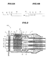
FIGS. 5A and 5B are explanatory diagrams showing a first connecting terminal, whereinFIGS. 5A is a side view thereof andFIGS. 5B is a bottom view thereof; -
FIG. 6 is a cross sectional view showing the second connector portion; -
FIGS. 7A and 7B are explanatory diagrams showing a second connecting terminal, whereinFIGS. 7A is a side view thereof andFIGS. 7B is a bottom view thereof, -
FIGS. 8A and 8B are explanatory diagrams showing a second connecting terminal, whereinFIG. 8A is a side view thereof andFIG. 8B is a bottom view thereof; and -
FIG. 9 is a cross sectional view of a connector in a second embodiment when the first connector portion and the second connector portion are mated. - Next, preferred embodiments according to the present invention will be explained below in more detail in conjunction with appended drawings.
- Firstly, a connector in a first embodiment according to the present invention will be explained below.
-
FIG. 1 is a perspective view showing afirst connector portion 2 and asecond connector portion 3 composing a connector 1 in the first embodiment according to the present invention.FIG. 2 is a perspective view showing the connector 1 when thefirst connector portion 2 and thesecond connector portion 3 are mated.FIG. 3 is a cross sectional view of the connector 1 when thefirst connector portion 2 and thesecond connector portion 3 are mated. InFIGS. 1 and 2 , a braidedshield 31 and a rubber boot 39 to be described later are omitted. In addition, a recess to which a hexagon wrench (hexagonal spanner) is mated is formed at an upper surface of a head portion 9a of abolt 12 as a connectingmember 9, however, the recess is omitted fromFIGS. 1 to 3 . (The connector 1 structure) - As shown in
FIG. 1 to 3 , the connector 1 in this embodiment comprises afirst connector portion 2 and asecond connector portion 3 mated with each other, to thereby collectively connect a plurality of power lines. - More specifically, the connector 1 includes the
first connector portion 2 having afirst housing 5 with a plurality of (three) first connecting terminals (male terminals) 4a to 4c aligned and accommodated therein, and thesecond connector portion 3 having asecond housing 7 with a plurality of (three) second connecting terminals (female terminals) 6a to 6c aligned and accommodated therein. When thefirst housing 5 of thefirst connector portion 2 and thesecond housing 7 of thesecond connector portion 3 are mated with each other, the first connectingterminals 4a to 4c and the second connectingterminals 6a to 6c face each other to form pairs, respectively, and result in a stacked structure of the pairs of the first connectingterminals 4a to 4c and the second connectingterminals 6a to 6c alternately interleaved. - This connector 1 is used for connection of a vehicle drive motor and an inverter for diving that motor, for example.
- More specifically, the
first housing 5 of the first connector portion 2 (inFIG. 1 , left side portion) is mated with a shield case of the motor, and the first connecting terminal 4a to 4c portions exposed from thefirst housing 5 are connected to terminals, respectively, of a terminal block installed in the shield case of the motor. Mating to thisfirst connector portion 2 thesecond connector portion 3 electrically connected with the inverter results in electrical connection of the motor and the inverter. Although the foregoing is concerned with the motor side connection, the same applies to the inverter side connection. - Below are described the respective specific structures of the
first connector portion 2 and thesecond connector portion 3. - Referring to
FIG. 4 , thefirst connector portion 2 has the three first connectingterminals 4a to 4c held therein to be aligned at a specified pitch, and includes thefirst housing 5 for accommodating the three aligned first connectingterminals 4a to 4c, substantially rectangularparallelepiped isolating members 8a to 8d provided in thefirst housing 5 for isolating each of the first connectingterminals 4a to 4c, and a connectingmember 9 with a head 9a and ashaft 9b connected to the head 9a, whoseshaft 9b penetrates each contact between the first connectingterminals 4a to 4c and the second connectingterminals 6a to 6c and the isolatingmembers 8a to 8d, and whose head 9a is pressed against the adjacent isolatingmember 8a, to thereby collectively fix the first connectingterminals 4a to 4c and the second connectingterminals 6a to 6c at the contacts therebetween, for electrical connections between the first connectingterminals 4a to 4c and the second connectingterminals 6a to 6c, respectively. At least a portion of the connectingmember 9, which penetrates each contact, is formed of an insulating material. - The
first housing 5 may be a male housing (male side housing) or a female housing (female side housing). Herein, the case that thefirst housing 5 is the male side housing is explained as an example - The first connecting
terminals 4a to 4c are plate terminals, and are held to be aligned at a specified pitch by being spaced apart from each other by a moldedresin material 10 formed of an insulating resin (e.g. PPS (polyphenylene sulfide) resin, PPA (polyphthalamide) resin, PA (polyamide) resin, PBT (polybutylene terephthalate), epoxy based resin), which forms a portion of thefirst housing 5. As a method for holding the first connectingterminals 4a to 4c with the moldedresin material 10, there is a holding method by inserting the first connectingterminals 4a to 4c during molding of the moldedresin material 10 and then curing the resin, or a holding method by pressing the first connectingterminals 4a to 4c into the moldedresin material 10 which has been molded beforehand. - The first connecting
terminals 4a to 4c are supplied with electricity at different voltages and/or currents, respectively. For example, in this embodiment, power lines are assumed to be for three phase alternating current between a motor and an inverter, so that the first connectingterminals 4a to 4c are supplied with alternating currents, respectively, which are 120 degrees out of phase with each other. For the purpose of reducing the loss of power transmitted through the connector 1, the first connectingterminals 4a to 4c may each be formed of a metal such as a high conductivity silver, copper, aluminum, or the like Also, the first connectingterminals 4a to 4c each have slight flexibility. - The isolating
members 8a to 8d comprise the plurality of first isolatingmembers 8a to 8c aligned and accommodated in thefirst housing 5, and integrally fixed to one side of the first connectingterminals 4a to 4c, respectively, (i.e. to the opposite side to the side joined with the second connectingterminals 6a to 6c), and the second isolatingmember 8d provided to be integrally fixed to an inner surface of thefirst housing 5, and to face one side of the second connectingterminal 6c (i.e the opposite side to the side joined with the first connectingterminal 4c) positioned at the outermost side when stacking the first connectingterminals 4a to 4c and the second connectingterminals 6a to 6c. - The isolating
members 8a to 8d are fixed at such a position as to protrude from the tips of the first connectingterminals 4a to 4c. Each of these isolatingmembers 8a to 8d is chamfered at each of its corners on the second connecting terminal 6a to 6c inserting / removing side. Also, referring toFIG. 5A and 5B, each of the first isolatingmembers 8a to 8c is formed with a protruding portion (thickened surface) 11 of its surface fixed to the first connectingterminals 4a to 4c to fill the level difference therebetween, so that the lower surfaces (in the figure, the lower sides) of the first isolatingmembers 8a to 8c are coplanar with the lower surfaces (in the figure, the lower sides) of the first connectingterminals 4a to 4c, respectively. With this configuration, when thefirst connector portion 2 and thesecond connector portion 3 are mated with each other, the tips of the first connectingterminals 4a to 4c do not contact the inserted tips of the second connecting terminal 6a to 6c. The insertability of the second connecting terminal 6a to 6c is therefore enhanced. InFIG 5A , the structure of the first isolatingmember 8a is depicted as being simplified, and the first isolatingmembers 8a to 8c are depicted likewise. - Referring again to
FIG. 4 , the connectingmember 9 comprises a bolt (cap bolt) 12 made of a metal (e.g. SUS, iron, copper alloy, or the like) and an insulatinglayer 13 formed of an insulating resin material (e.g. PPS (polyphenylene sulfide) resin, PPA (polyphthalamide) resin, PA(polyamide) resin, PBT (polybutylene terephthalate), epoxy based resin), which coats a perimeter of theshaft 9b (including the portion penetrating each contact) of thatbolt 12. - The entire connecting
member 9 formed of an insulating resin may be used, but the connectingmember 9 coated with the insulatinglayer 13 around the perimeter of theshaft 9b of themetallic bolt 12 is preferable from the point of view of strength. That is, the connectingmember 9 having a combined structure of themetallic bolt 12 and the insulatinglayer 13 made of an insulating resin can have enhanced strength, compared to the entire connectingmember 9 formed of an insulating resin. As the insulating resin for coating themetallic bolt 12, it is preferred to use an insulating resin, which has a linear expansion coefficient approximate to a linear expansion coefficient of a metal forming thebolt 12, so as to prevent creep. - The head 9a of the connecting
member 9 is provided with a packing 14 therearound for preventing water from penetrating into thefirst housing 5. Also, between the lower surface of the head 9a of the connectingmember 9 and the upper surface of the first isolatingmember 8a directly therebelow is provided anelastic member 15 for applying a specified pressing force to the first isolatingmember 8a. Theelastic member 15 is a spring made of a metal (e.g. SUS, or the like). In this embodiment, theelastic member 15 constitutes a portion of the connectingmember 9. - The first isolating
member 8a to be in contact with a lower portion of theelastic member 15 is formed with a recessedportion 16 in its upper surface which covers (accommodates) the lower portion of theelastic member 15. At the bottom of the recessed portion 16 (i.e. the base to be in contact with the lower portion of the elastic member 15) is provided a receivingmember 17 made of a metal (e.g. SUS, or the like) which receives theelastic member 15 and which is for preventing damage to the first isolatingmember 8a formed of an insulating resin. - This connecting
member 9 is inserted into thefirst housing 5 from above the first connecting terminal 4a to 4c surfaces (inFIG. 4 , the upper surfaces) to which are fixed the first isolatingmembers 8a to 8c, respectively. A screwingportion 18 at a tip of theshaft 9b is then screwed into ascrew hole 19 formed in an inner surface of thefirst housing 5, to thereby allow the connectingmember 9 to press the first connectingterminals 4a to 4c and the second connectingterminals 6a to 6c from its head 9a toward the tip of itsshaft 9b (inFIG. 4 , downward from above), and collectively fix the first connectingterminals 4a to 4c and the second connectingterminals 6a to 6c at the contacts therebetween, for electrical connections between the first connectingterminals 4a to 4c and the second connectingterminals 6a to 6c, respectively. - The
first housing 5 is formed of a cylindricalhollow body 20 which is substantially rectangular in transverse cross section. An outer portion at one end (in the figure, at the right end) of thecylindrical body 20 mated with thesecond housing 7 is formed in a tapered shape, taking the mateability with thesecond connector portion 3 into consideration. Also, in the outer portion at one end of thecylindrical body 20 is provided a terminalhousing waterproofing structure 21 for sealing between thefirst connector portion 2 and thesecond connector portion 3. The terminalhousing waterproofing structure 21 is formed of a recessedportion 22 formed in an outer portion at the open end of thecylindrical body 20, and a packing 23 provided in the recessedportion 22, such as an O-ring - In the other end (in the figure, in the left end) of the
cylindrical body 20 is accommodated a moldedresin material 10 with the first connectingterminals 4a to 4c aligned and held therewith. In an outer portion at the other end of thecylindrical body 20 is formed a flange 24 (an attachment hole omitted) for fixing thefirst connector portion 2 to a device casing (e.g. a motor shield case). At arim 25 of theflange 24 having the attachment hole for bolt insertion and fixation to a device casing may be provided a packing for sealing between thefirst connector portion 2 and the device casing. The structure of thisflange 24 is not assumed as fixing thefirst connector portion 2 to a device casing, but theflange 24 may be provided in thesecond connector portion 3, or in both thefirst connector portion 2 and thesecond connector portion 3 Also, both of thefirst connector portion 2 and thesecond connector portion 3 may be free or not fixed to a device casing. - Also, this
flange 24 is effective in enhancing the dissipation of heat. That is, the formation of theflange 24 permits a large surface area of thefirst housing 5, thereby allowing enhancement in the dissipation to outside via thefirst housing 5, of heat produced inside the first connector portion 2 (e.g. heat produced at each contact). - In an upper portion (in the figure, in the upper side) of the
cylindrical body 20 is formed a connectingmember insertion hole 26 for inserting the connectingmember 9. The connectingmember insertion hole 26 is formed in a cylindrical shape, and bent inward at a lower end (in the figure, at the lower side) of that cylindrical shape. A rim of the lower surface of the head 9a of the connectingmember 9 is contacted with this bent portion of the connectingmember insertion hole 26, to thereby regulate the stroke of the connectingmember 9. - For shielding performance, heat dissipation, and weight reduction of the connector 1, the
cylindrical body 20 is formed of, preferably a high electrical conductivity, high thermal conductivity and lightweight metal such as an aluminum, but may be formed of a resin, or the like In the case that thefirst housing 5 is formed of an insulating resin, the second isolatingmember 8d and thefirst housing 5 may integrally be formed of the insulating resin. Thecylindrical body 20 formed of an aluminum as mentioned above allows the connectingmember 9 to be firmly tightened into thescrew hole 19 when screwed thereinto, compared with thecylindrical body 20 formed of an insulating resin. - Referring to
FIG. 6 , thesecond connector portion 3 has thesecond housing 7 with a plurality of (three) second connecting terminals (female terminals) 6a to 6c aligned and accommodated therein. Herein, a connector portion on the female terminal side is called as "second connector portion 3". Thesecond housing 7 may be a male housing (male side housing) or a female housing (female side housing). Herein, the case that thesecond housing 7 is the female side housing is explained as an example. - The second connecting
terminals 6a to 6c are connected withcables 27a to 27c, respectively, at one end, which extend from an inverter. Thesecables 27a to 27c are electrically connected to the first connectingterminals 4a to 4c via the second connectingterminals 6a to 6c, respectively, and therefore supplied with electricity at voltages and/or currents in correspondence to the second connectingterminals 6a to 6c, respectively. Thecables 27a to 27c are constructed by forming an insulatinglayer 29 around aconductor 28. In this embodiment, theconductor 28 used has a cross section of 20 mm2. - The
cables 27a to 27c are held to be aligned at a specified pitch by a multi-cylindrical (i.e. plurality of cylinders are aligned)cable holding member 30. With thiscable holding member 30, when thefirst connector portion 2 and thesecond connector portion 3 are mated with each other., the second connectingterminals 6a to 6c are held to be positioned below the first connectingterminals 4a to 4c to face (i.e. to be connected to) the second connectingterminals 6a to 6c to form pairs respectively. - The
cable holding member 30 is formed of an insulating resin, to isolate the second connectingterminals 6a to 6c from each other to prevent a short circuit Thiscable holding member 30 allows the second connectingterminals 6a to 6c to be held at specified positions respectively, even when thecables 27a to 27c respectively connected to the second connectingterminals 6a to 6c have excellent flexibility. That is, in this embodiment, thecables 27a to 27c to be used can have excellent flexibility, and therefore enhance a degree of freedom of wiring thecables 27a to 27c. - Although the second connecting
terminals 6a to 6c are positioned by thecable holding member 30 holding thecables 27a to 27c, more specifically, the ends near the second connectingterminals 6a to 6c of thecables 27a to 27c to hold the second connectingterminals 6a to 6c at specified positions respectively, the second connectingterminals 6a to 6c may be positioned by thecable holding member 30 holding thecables 27a to 27c, and the second connectingterminals 6a to 6c directly. Also, a connecting terminal holding member may, in place of thecable holding member 30, be used that holds not thecables 27a to 27c, but the second connectingterminals 6a to 6c directly. - In the case that, with the
cable holding member 30, the second connectingterminals 6a to 6c are positioned by holding thecables 27a to 27c without directly holding the second connectingterminals 6a to 6c, that is, in the case of this embodiment, making thecables 27a to 27c flexible allows the tips of the second connectingterminals 6a to 6c to have flexibility relative to thesecond housing 7. This construction permits flexible adaptation, even to deformation of first connecting terminal 4a to 4c portions to insert the second connectingterminals 6a to 6c in thefirst connector portion 2, when pressed by the connectingmember 9. - Also, a
braided shield 31 is wrapped aroundcables 27a to 27c portions drawn out of thesecond housing 7, for the purpose of enhancement in shielding performance. This braidedshield 31 is contacted with a later-describedcylindrical shield body 41, and electrically connected to the first housing 5 (to be equipotential (GND)) through thecylindrical shield body 41. - Referring to
FIG. 7 and8 , the second connectingterminals 6a to 6c respectively include calkingportions 32 for calking theconductors 28 exposed from the tips of thecables 27a to 27c, andU-shaped contacts 33 formed integrally with the calkingportions 32. At tips of theU-shaped contacts 33 are respectively formedtapered portions 34 to enhance the insertability of theU-shaped contacts 33. When thefirst connector portion 2 and thesecond connector portion 3 are mated with each other, theU-shaped contacts 33 are inserted in such a manner as to grip theshaft 9b of the connectingmember 9. - In this embodiment, to reduce the size of the connector 1, the
cables 27a to 27c are configured to be aligned and held as close to each other as possible. To this end, as shown inFIG. 7 , atrunk 35 of the second connecting terminal 6b to be connected to thecable 27b arranged in the middle when aligned is bent, to thereby space the second connectingterminals 6a to 6c apart at the same pitch. - The second connecting
terminals 6a to 6c may each be constructed of a high electrical conductivity metal such as silver, copper, aluminum, or the like, in order to reduce the loss of power transmitted through the connector 1. Also, the second connectingterminals 6a to 6c each have slight flexibility. - Referring again to
FIG. 6 , thesecond housing 7 is formed of a cylindricalhollow body 36 which is substantially rectangular in transverse cross section. To mate thefirst housing 5 into thesecond housing 7, an inner portion at one end (in the figure, at the left end) of thecylindrical body 36 mated with thefirst housing 5 is formed in a tapered shape, taking the mateability with thefirst housing 5 into consideration. - Alternatively, the
first housing 5 and thesecond housing 7 may be configured such that thesecond housing 7 is mated into thefirst housing 5, contrary to the above case, In this case, an inner portion at one end of thecylindrical body 20 composing thefirst housing 5 may be formed in a tapered shape, an outer portion at one end of thecylindrical body 36 composing thesecond housing 7 may be formed in a tapered shape, and the housingwaterproof structure 21 may be formed around the outer portion at the one end of thecylindrical body 36. - In the other end (in the figure, in the right end) of the
cylindrical body 36 is accommodated thecable holding member 30 with thecables 27a to 27c aligned and held therewith. On a cable insertion side of thecable holding member 30 is formed apackingless sealing portion 37, to prevent water from penetrating onto thecables 27a to 27c and into thesecond housing 7. In an outer portion of thecable holding member 30 is provided a packing 38 to be in contact with an inner surface of thefirst housing 5. That is, the connector 1 has a double waterproofing structure of the packing 23 of the terminalhousing waterproofing structure 21 and the packing 38 provided in the outer portion of thecable holding member 30. - Further, the other end of the
cylindrical body 36 from which thecables 27a to 27c are drawn out is covered with a rubber boot 39 for preventing water from penetrating into thecylindrical body 36. - Also, in an upper portion (in the figure, in the upper side) of the
cylindrical body 36 is formed a connectingmember manipulation hole 40 for manipulating the connectingmember 9 provided in thefirst connector portion 2 when thefirst connector portion 2 and thesecond connector portion 3 are mated with each other. - For shielding performance, heat dissipation, and weight reduction of the connector 1, the
cylindrical body 36 is formed of, preferably a high electrical conductivity, high thermal conductivity and lightweight metal such as an aluminum, but may be formed of a resin, or the like. In this embodiment, thecylindrical body 36 is formed of an insulating resin. Therefore, to enhance its shielding performance and heat dissipation, thecylindrical shield body 41 made of aluminum is provided on an inner surface at the other end of thecylindrical body 36 - The
cylindrical shield body 41 has acontact 42 to be contacted with an outer portion of thefirst housing 5 made of an aluminum when thefirst connector portion 2 and thesecond connector portion 3 are mated with each other. Thecylindrical shield body 41 is thermally and electrically connected with thefirst housing 5 via thiscontact 42. This enhances the shielding performance and the heat dissipation. In particular, the heat dissipation is likely to be significantly enhanced by positively allowing heat to escape toward thefirst housing 5 having an excellent heat dissipation property. - (Connection between the first connecting
terminals 4a to 4c and the second connectingterminals 6a to 6c) - Next is described the connection between the first connecting
terminals 4a to 4c and the second connectingterminals 6a to 6c using the connector 1 in this embodiment. - When the
first connector portion 2 and thesecond connector portion 3 are mated with each other from an unmated state as shown, the second connectingterminals 6a to 6c are inserted between the first connecting terminal 4a with the isolatingmember 8a and the isolatingmember 8b, between the first connecting terminal 4b with the isolatingmember 8b and the isolatingmember 8c, and between the first connectingterminal 4c with the isolatingmember 8c and the isolatingmember 8d, respectively, where the first connectingterminals 4a to 4c and the second connectingterminals 6a to 6c form pairs respectively With that insertion, the first connectingterminals 4a to 4c and the second connectingterminals 6a to 6c then face each other to form pairs, respectively, and result in a stacked structure in which the pairs of the first connectingterminals 4a to 4c and the second connectingterminals 6a to 6c and the isolatingmembers 8a to 8d are disposed alternately, i.e. the pairs of the first connectingterminals 4a to 4c and the second connectingterminals 6a to 6c are alternately interleaved with the isolatingmembers 8a to 8d. - In this case, inside the
first connector portion 2, the isolatingmembers 8a to 8c are respectively fixed to the tips of the first connectingterminals 4a to 4c held to be aligned at a specified pitch. A pitch between the isolatingmembers JP Patent No.4037199 members terminals 6a to 6c to be easily inserted between the first connecting terminal 4a with the isolatingmember 8a and the isolatingmember 8b, between the first connecting terminal 4b with the isolatingmember 8b and the isolatingmember 8c, and between the first connectingterminal 4c with the isolatingmember 8c and the isolatingmember 8d, respectively, where the first connectingterminals 4a to 4c and the second connectingterminals 6a to 6c form the pairs respectively. That is, the insertability / removability of the second connectingterminals 6a to 6c is unlikely to deteriorate Also, because of no need to provide a holding jig for holding the pitch between the isolatingmembers - Also, the contact between the first connecting
terminal 4a (or 4b) and the second connectingterminal 6a (or 6b) is sandwiched between the first isolatingmember 8a (or 8b) fixed to the first connectingterminal 4a (or 4b) constituting the contact, and the first isolatingmember 8b (or 8c) fixed to the first connectingterminal 4b (or 4c) constituting the other contact. Likewise, the contact between the first connectingterminal 4c and the second connectingterminal 6c is sandwiched between the first isolatingmember 8c fixed to the first connectingterminal 4c constituting the contact, and the second isolatingmember 8d fixed to the inner surface of thefirst housing 5. - Referring to
FIG. 3 , following that, the connectingmember 9 is manipulated through the connectingmember manipulation hole 40, to screw and tighten the screwingportion 18 of the connectingmember 9 into thescrew hole 19 of thefirst housing 5. The connectingmember 9 is then rotated and pressed into the bottom of thescrew hole 19, and causes theelastic member 15 to, in turn, press the first isolatingmember 8a, the first isolatingmember 8b, the first isolatingmember 8c, and the second isolatingmember 8d, and sandwich the contacts between the isolatingmembers members members members terminals 4a to 4c and the second connectingterminals 6a to 6c are slightly bent and contacted with each other, respectively, in a wide range. This allows each contact to be firmly contacted and fixed, even in a vibrational environment such as on vehicle. - Also, although in this embodiment, the first connecting
terminals 4a to 4c and the second connectingterminals 6a to 6c are in surface contact with each other respectively, the first connecting terminal 4a to 4c contact side surfaces to be contacted with the second connectingterminals 6a to 6c may be formed with protruding portions, andU-shaped contacts 33 of the second connectingterminals 6a to 6c may be configured to be mated onto these protruding portions, respectively. This configuration allows the further stabilization of the coupling force of the first connectingterminals 4a to 4c and the second connectingterminals 6a to 6c, respectively. That is, this configuration is especially effective for vibration perpendicular to the connectingmember 9. - Also, although in this embodiment, lengths of branch tips of each
U-shaped contact 33 of the second connectingterminals 6a to 6c are the same, one length thereof may be formed to be long to form a J-shaped contact. The J-shaped contact allows thesecond connector portion 3 to be inserted into theshaft 9b of the connectingmember 9 obliquely relative to the cable longitudinal direction. - Although in this embodiment, the
screw hole 19 is formed at such a position as to be screwed onto the screwingportion 18 at the tip of the connectingmember 9, the screwingportion 18 may be formed in the head 9a of the connectingmember 9, and thescrew hole 19 may be formed to be screwed onto the screwingportion 18 formed in the head 9a. - Also, although in this embodiment, the
screw hole 19 is formed in thefirst housing 5, only a through hole, not thescrew hole 19 may be formed in thefirst housing 5, and thescrew hole 19 may be formed in thesecond housing 7. Also, thescrew hole 19 may be formed both in thefirst housing 5 and thesecond housing 7. - Although the connector 1 in this embodiment has been described, one of the features of the connector 1 in this embodiment is that, unlike a later-described
connector 100 in a second embodiment, theshaft 9b of the connectingmember 9 penetrates each contact between the first connectingterminals 4a to 4c and the second connectingterminals 6a to 6c and the isolatingmembers 8a to 8d. This configuration allows the facilitation of the constant respective positional relationships of between the first connectingterminals 4a to 4c and the second connectingterminals 6a to 6c relative to the connectingmember 9 as a center. - Next is described a
connector 100 in a second embodiment according to the invention, referring toFIG. 9 . - As shown in
FIG. 9 , theconnector 100 in this embodiment is different from the previously described connector 1 in the first embodiment, in that the connectingmember 9 does not penetrate each contact between the first connectingterminals 4a to 4c and the second connectingterminals 6a to 6c and the isolatingmembers 8a to 8d. That is, in this embodiment, the connectingmember 9 is consisted of only the head 9a serving as the pressing portion. - In the connector 1 in the first embodiment, the screwing
portion 18 formed in theshaft 9b is screwed into thescrew hole 19 of thefirst housing 5 to thereby tighten the connectingmember 9 into thefirst housing 5, whereas in theconnector 100 in this embodiment, the connectingmember 9 is formed of only the head 9a, and theconnector 100 is therefore configured so that amale screwing portion 43 is formed in such a manner as to avoid the packing 14 around the head 9a, while afemale screw 44 into which the screwingportion 43 is screwed is cut in an inner portion of the connectingmember insertion hole 26 of thefirst housing 5, to screw the screwingportion 43 into thefemale screw 44 and thereby tighten the connectingmember 9 into thefirst housing 5. - As shown in
FIG. 9 , the head 9a is shaped to have a large diameter portion provided with the packing 14 and a small diameter portion formed with themale screwing portion 43, and to shape the connectingmember insertion hole 26 to have those two diameter dimensions. With this configuration, when the head 9a is tightened into the connectingmember insertion hole 26, themale screwing portion 43 is not disposed in a portion facing the packing 14 This can therefore ensure its effective waterproofing structure. - Also, on a lower surface of the head 9a of the connecting member 9 (on the lower surface facing the first isolating
member 8a) is formed an elasticmember holding portion 45 for engaging and holding theelastic member 15. Theelastic member 15 is held by this elasticmember holding portion 45 to form a portion of the connectingmember 9 - The connection of the first connecting
terminals 4a to 4c and the second connecting terminal 6a to 6c using thisconnector 100 is performed in the same procedure as that of the previously described connector 1 in the first embodiment. That is, the mating of thefirst connector portion 2 and thesecond connector portion 3 is followed by tightening themale screwing portion 43 of the connectingmember 9 into thefemale screw 44 of thefirst housing 5, concurrently with this, sequentially exerting the pressing force of theelastic member 15 to the isolatingmembers 8a to 8d, and pressing the contacts to be sandwiched between the isolatingmembers terminals 4a to 4c and the second connectingterminals 6a to 6c, respectively. This allows the first connectingterminals 4a to 4c and the second connectingterminals 6a to 6c to be firmly fixed to each other respectively. - Also, in this embodiment, since the connecting
member 9 does not penetrate each contact between the first connectingterminals 4a to 4c and the second connectingterminals 6a to 6c and the isolatingmembers 8a to 8d, there is no need to form the contacts of the second connectingterminals 6a to 6c in such a shape as to avoid the connecting member 9 (e.g. in the previously mentioned U-shape) - Although the
connector 100 in the second embodiment has been described, one of the features of theconnector 100 in the second embodiment is that, unlike the previously describedconnector 100 in the first embodiment, the connectingmember 9 does not penetrate each contact between the first connectingterminals 4a to 4c and the second connectingterminals 6a to 6c and the isolatingmembers 8a to 8d. This configuration results from fixing the isolatingmembers 8a to 8c to the other surfaces of the first connectingterminals 4a to 4c respectively, and can ensure the cost reduction of the connectingmember 9. Also, this leads to the weight reduction of the connectingmember 9, thus allowing a contribution to the weight reduction of the entire connector. - The invention is not limited to the above-described embodiments, but various alterations are possible in the scope not departing from the gist of the invention.
- Also, although in this embodiment, three phase alternating power lines have been assumed, according to the technical idea of the invention, the connector for a vehicle, for example, may be configured to collectively connect lines for different uses, such as three phase alternating current power lines for between a motor and an inverter, two phase direct current power lines for an air conditioner, and the like. This configuration allows power lines for a plurality of uses to be collectively connected by one connector. There is therefore no need to prepare a different connector tor each use, to thereby allow a contribution to space saving or low cost.
- Also, although in this embodiment, when viewed from the head 9a of the connecting
member 9, the first connectingterminals 4a to 4c and the second connectingterminals 6a to 6c have been configured to be linearly contacted with each other respectively, thefirst housing 5 and thesecond housing 7 may be configured so that, when viewed from the head 9a of the connectingmember 9, the first connectingterminals 4a to 4c of thefirst connector portion 2 cross and contact the second connectingterminals 6a to 6c of thesecond connector portion 3 respectively at a right angle thereto. That is, thefirst connector portion 2 and thesecond connector portion 3 may be mated with each other in an L-shape. Likewise, thesecond housing 7 and the second connectingterminals 6a to 6c may be configured to be disposed obliquely relative to thefirst housing 5 and the first connectingterminals 4a to 4c respectively. By thus applying the gist of the invention, the direction of inserting / removing thesecond connector portion 3 relative to thefirst connector portion 2 may be varied. That is, the direction of drawing the cables out from the connector can be mated to the shape of an installation portion, to thereby allow a contribution to space saving. - Also, the terminal surfaces of the first connecting
terminals 4a to 4c and the second connectingterminals 6a to 6c may be knurled to make their frictional force large, so that the terminals are thereby unlikely to move relative to each other, and are firmly fixed at the contacts therebetween respectively. - Also, although in this embodiment, it has been described that, unlike the second connecting
terminals 6a to 6c, the first connecting terminal 4a to 4c are not connected with cables respectively, the first connectingterminals 4a to 4c are not limited to this structure. Theconnector 100 in this embodiment may be used for connecting cables to each other. - Also, although in this embodiment, the
cables 27a to 27c used have excellent flexibility, rigid cables may be used - Also, although in this embodiment, the
bolt 12 has been described as the example of the connectingmember 9, the connectingmember 9 configuration is not limited to bolt shape. For example, a shaft of a CPA (Connector Position Assurance) lever which fixes mating between thefirst connector portion 2 and thesecond connector portion 3 may be configured as the connectingmember 9, in which the CPA lever is rotated to fix the mating and to press (or tighten) the connectingmember 9 from the head 9a of the connectingmember 9 toward a tip end of theshaft 9b. - Also, in this embodiment, the head 9a of the
bolt 12 as the connectingmember 9 is formed with a recess in its upper surface (more specifically, at the center of the upper surface), into which a hexagon wrench (hexagonal spanner) is mated. Although in this embodiment, the specified manipulation tool has been assumed as being a commercial hexagon wrench, the head 9a of thebolt 12 as the connectingmember 9 may be formed with a recess having a shape corresponding to the specified manipulation tool that is not commercialized, with assuming that the non-commercial specified manipulation tool is used. - Also, in this embodiment, the use orientation of the connector is such that the connecting
member 9 may be substantially horizontal or substantially vertical In other words, the use conditions of the connector in this embodiment require no use orientation. - Also, although in this embodiment, the head 9a of the connecting
member 9 is pressed against the adjacent isolatingmember 8a via theelastic member 15 constituting a portion of the connectingmember 9, the head 9a may be pressed directly against the adjacent isolatingmember 8a, not via theelastic member 15.
Claims (10)
- A connector, comprising:a first connector portion comprising a first housing with a plurality of first connecting terminals aligned and accommodated therein;a second connector portion comprising a second housing with a plurality of second connecting terminals aligned and accommodated therein, when the first connector portion and the second connector portion being mated with each other, one side of the first connecting terminals and one side of the second connecting terminals facing each other to form pairs, respectively, and resulting in a stacked structure of the pairs of the first connecting terminals and the second connecting terminals alternately interleaved;a plurality of isolating members aligned and accommodated in the first housing of the first connector portion, further fixed to other side of the first connecting terminals, respectively; anda connecting member for pressing the adjacent isolating member, to thereby collectively fix the first connecting terminals and the second connecting terminals at the contacts therebetween, for electrical connections between the first connecting terminals and the second connecting terminals, respectively.
- The connector according to claim 1, wherein the connecting member comprises a head and a shaft connected to the head, the shaft, penetrating each contact between the first connecting terminals and the second connecting terminals as well as the isolating members, the head pressing the adjacent isolating member, to thereby collectively fix the first connecting terminals and the second connecting terminals at the contacts therebetween, for electrical connections between the first connecting terminals and the second connecting terminals, respectively, at least a portion of the connecting member, which penetrates each contact, being formed of an insulating material.
- The connector according to claim 1 or 2, wherein each of the isolating members is substantially rectangular parallelepiped and chamfered at each of its corners on a side to which the second connecting terminals are inserted and removed.
- The connector according to claim 1, 2 or 3, wherein each of the first isolating members is formed with a protruding portion of its surface fixed to the first connecting terminals to fill a level difference therebetween.
- The connector according to claim 2, wherein the isolating member comprises a first isolating member, and the connector further comprises a second isolating member provided to be fixed to an inner surface of the first housing, and to face other side of the second connecting terminal positioned at an outermost side when stacking the first connecting terminals and the second connecting terminals.
- The connector according to claim 5, wherein the second isolating member and the first housing are integrally molded by an insulative resin.
- The connector according to claim 5 or 6, wherein each of the first isolating members and the second isolating member is substantially rectangular parallelepiped and chamfered at each of its corners on a side to which the second connecting terminals are inserted and removed.
- The connector according to claim 5, 6 or 7, wherein each of the first isolating members and the second isolating member is substantially rectangular parallelepiped and chamfered at each of its corners on a side to which the second connecting terminals are inserted and removed.
- The connector according to any of claims 5 to 8, wherein each of the first isolating members and the second isolating member is formed with a protruding portion of its surface fixed to the first connecting terminals to fill a level difference therebetween,
- The connector according to any of claims 1 to 9, wherein a flexible cable is connected to one end of each of the second connecting terminals and the second connector portion is provided with a cable holding member that allows the second connecting terminals to be held with flexibility at specified positions respectively by holding the cable.
Applications Claiming Priority (1)
| Application Number | Priority Date | Filing Date | Title |
|---|---|---|---|
| JP2009272315A JP4905542B2 (en) | 2009-11-30 | 2009-11-30 | connector |
Publications (2)
| Publication Number | Publication Date |
|---|---|
| EP2328239A1 true EP2328239A1 (en) | 2011-06-01 |
| EP2328239B1 EP2328239B1 (en) | 2012-06-27 |
Family
ID=43530883
Family Applications (1)
| Application Number | Title | Priority Date | Filing Date |
|---|---|---|---|
| EP10190423A Not-in-force EP2328239B1 (en) | 2009-11-30 | 2010-11-09 | Connector |
Country Status (4)
| Country | Link |
|---|---|
| US (1) | US7892038B1 (en) |
| EP (1) | EP2328239B1 (en) |
| JP (1) | JP4905542B2 (en) |
| CN (1) | CN102082346B (en) |
Cited By (1)
| Publication number | Priority date | Publication date | Assignee | Title |
|---|---|---|---|---|
| EP2469658A3 (en) * | 2010-12-21 | 2013-01-02 | Hitachi Cable, Ltd. | Connector |
Families Citing this family (15)
| Publication number | Priority date | Publication date | Assignee | Title |
|---|---|---|---|---|
| JP5293627B2 (en) * | 2010-02-01 | 2013-09-18 | 日立電線株式会社 | connector |
| JP5598758B2 (en) * | 2010-08-26 | 2014-10-01 | 日立金属株式会社 | connector |
| JP5401671B2 (en) * | 2010-08-26 | 2014-01-29 | 日立金属株式会社 | connector |
| JP5760882B2 (en) * | 2011-01-13 | 2015-08-12 | 日立金属株式会社 | connector |
| JP5589858B2 (en) * | 2011-01-14 | 2014-09-17 | 日立金属株式会社 | connector |
| JP5831061B2 (en) * | 2011-01-19 | 2015-12-09 | 日立金属株式会社 | connector |
| JP5648591B2 (en) * | 2011-06-16 | 2015-01-07 | 日立金属株式会社 | Connector device |
| JP5673479B2 (en) * | 2011-10-14 | 2015-02-18 | 日立金属株式会社 | Connector device |
| CN103972746B (en) * | 2013-01-31 | 2017-01-18 | 富士康(昆山)电脑接插件有限公司 | Cable connector subassembly and cable thereof |
| JP5991260B2 (en) * | 2013-04-24 | 2016-09-14 | 日立金属株式会社 | Connector and wire harness |
| JP6107376B2 (en) | 2013-04-24 | 2017-04-05 | 日立金属株式会社 | Connector and wire harness |
| JP6653623B2 (en) * | 2015-12-16 | 2020-02-26 | 日本圧着端子製造株式会社 | Electrical connector |
| EP4280392A4 (en) * | 2021-01-15 | 2024-07-03 | Honda Motor Co., Ltd. | Electrical connector |
| US11881653B2 (en) * | 2021-11-24 | 2024-01-23 | Caterpillar Inc. | System and method for positioning a conductive rod powering a work machine |
| US11859370B2 (en) * | 2021-11-24 | 2024-01-02 | Caterpillar Inc. | Multi-tiered interface between conductor rod and work machine |
Citations (5)
| Publication number | Priority date | Publication date | Assignee | Title |
|---|---|---|---|---|
| JPH0437199B2 (en) | 1982-06-07 | 1992-06-18 | Mitsubishi Oil Co | |
| US5785542A (en) * | 1996-02-15 | 1998-07-28 | Qbc, Inc. | Electrical distribution system having an improved bus coupler |
| JP2004056924A (en) * | 2002-07-19 | 2004-02-19 | Honda Motor Co Ltd | Vehicle electrical connection structure and terminal connection structure |
| US20050186814A1 (en) * | 2004-02-19 | 2005-08-25 | Thomas Vogel | Electrical connector for shielded cables |
| JP2009070754A (en) | 2007-09-18 | 2009-04-02 | Hitachi Cable Ltd | Lever type connector |
Family Cites Families (11)
| Publication number | Priority date | Publication date | Assignee | Title |
|---|---|---|---|---|
| US1917009A (en) * | 1931-03-17 | 1933-07-04 | Bell Telephone Labor Inc | Electrical connecter |
| TW238431B (en) * | 1992-12-01 | 1995-01-11 | Stanford W Crane Jr | |
| JP3479773B2 (en) * | 2000-08-22 | 2003-12-15 | 日本航空電子工業株式会社 | Flat cable connector |
| JP3680792B2 (en) * | 2001-12-11 | 2005-08-10 | 三菱電機株式会社 | Multi-connector for high-speed communication apparatus and mounting method of multi-connector for high-speed communication apparatus and printed circuit board |
| TWM261868U (en) * | 2004-06-18 | 2005-04-11 | Advanced Connectek Inc | An electrical connector with a latch device |
| CN2772061Y (en) * | 2005-02-04 | 2006-04-12 | 上海莫仕连接器有限公司 | Electrical connector assembly |
| US7189120B2 (en) * | 2005-05-16 | 2007-03-13 | Molex Incorporated | Electrical connector with terminal vias |
| US7497736B2 (en) * | 2006-12-19 | 2009-03-03 | Fci Americas Technology, Inc. | Shieldless, high-speed, low-cross-talk electrical connector |
| JP4833826B2 (en) * | 2006-12-28 | 2011-12-07 | 三菱電線工業株式会社 | Connection member and harness connection body using the member |
| JP2009199743A (en) * | 2008-02-19 | 2009-09-03 | Japan Aviation Electronics Industry Ltd | Electrical connector |
| JP5315116B2 (en) * | 2009-04-08 | 2013-10-16 | 住電朝日精工株式会社 | Female connector for wire connection |
-
2009
- 2009-11-30 JP JP2009272315A patent/JP4905542B2/en not_active Expired - Fee Related
-
2010
- 2010-05-06 US US12/774,865 patent/US7892038B1/en not_active Expired - Fee Related
- 2010-07-28 CN CN201010243141.8A patent/CN102082346B/en not_active Expired - Fee Related
- 2010-11-09 EP EP10190423A patent/EP2328239B1/en not_active Not-in-force
Patent Citations (5)
| Publication number | Priority date | Publication date | Assignee | Title |
|---|---|---|---|---|
| JPH0437199B2 (en) | 1982-06-07 | 1992-06-18 | Mitsubishi Oil Co | |
| US5785542A (en) * | 1996-02-15 | 1998-07-28 | Qbc, Inc. | Electrical distribution system having an improved bus coupler |
| JP2004056924A (en) * | 2002-07-19 | 2004-02-19 | Honda Motor Co Ltd | Vehicle electrical connection structure and terminal connection structure |
| US20050186814A1 (en) * | 2004-02-19 | 2005-08-25 | Thomas Vogel | Electrical connector for shielded cables |
| JP2009070754A (en) | 2007-09-18 | 2009-04-02 | Hitachi Cable Ltd | Lever type connector |
Cited By (2)
| Publication number | Priority date | Publication date | Assignee | Title |
|---|---|---|---|---|
| EP2469658A3 (en) * | 2010-12-21 | 2013-01-02 | Hitachi Cable, Ltd. | Connector |
| US8523587B2 (en) | 2010-12-21 | 2013-09-03 | Hitachi Cable, Ltd. | Connector |
Also Published As
| Publication number | Publication date |
|---|---|
| US7892038B1 (en) | 2011-02-22 |
| JP2011113942A (en) | 2011-06-09 |
| EP2328239B1 (en) | 2012-06-27 |
| CN102082346B (en) | 2015-12-16 |
| JP4905542B2 (en) | 2012-03-28 |
| CN102082346A (en) | 2011-06-01 |
Similar Documents
| Publication | Publication Date | Title |
|---|---|---|
| EP2328239B1 (en) | Connector | |
| US8100708B2 (en) | Connection structure for a vehicle | |
| US7985092B2 (en) | Connection structure | |
| US7955110B1 (en) | Connector with a connecting member pressing insulators of terminals of two mating terminal housings | |
| US8123573B2 (en) | Connection structure | |
| US7959470B1 (en) | Connector with a connecting memer with a screw portion penetrating the insulators and terminals of two mating terminal housings | |
| US7922518B1 (en) | Connection structure | |
| US8105099B2 (en) | Lever connector | |
| US8277259B2 (en) | Connector | |
| JP5598758B2 (en) | connector | |
| US8182275B2 (en) | Lever connector with a connecting member manipulating mechanism for turning a turn lever to manipulate a connecting member | |
| US8226429B2 (en) | Connection structure | |
| US7980879B2 (en) | Connection structure | |
| US8202116B2 (en) | Connector for being capable of use for a portion to connect a power harness, which is used for large power transmission | |
| US8272887B2 (en) | Connector | |
| JP5308546B2 (en) | connector | |
| JP4905607B1 (en) | connector | |
| JP4905606B1 (en) | connector | |
| JP2012048948A (en) | Connector |
Legal Events
| Date | Code | Title | Description |
|---|---|---|---|
| PUAI | Public reference made under article 153(3) epc to a published international application that has entered the european phase |
Free format text: ORIGINAL CODE: 0009012 |
|
| AK | Designated contracting states |
Kind code of ref document: A1 Designated state(s): AL AT BE BG CH CY CZ DE DK EE ES FI FR GB GR HR HU IE IS IT LI LT LU LV MC MK MT NL NO PL PT RO RS SE SI SK SM TR |
|
| AX | Request for extension of the european patent |
Extension state: BA ME |
|
| 17P | Request for examination filed |
Effective date: 20111201 |
|
| GRAP | Despatch of communication of intention to grant a patent |
Free format text: ORIGINAL CODE: EPIDOSNIGR1 |
|
| RIC1 | Information provided on ipc code assigned before grant |
Ipc: H01R 13/621 20060101AFI20120113BHEP |
|
| GRAS | Grant fee paid |
Free format text: ORIGINAL CODE: EPIDOSNIGR3 |
|
| GRAA | (expected) grant |
Free format text: ORIGINAL CODE: 0009210 |
|
| AK | Designated contracting states |
Kind code of ref document: B1 Designated state(s): AL AT BE BG CH CY CZ DE DK EE ES FI FR GB GR HR HU IE IS IT LI LT LU LV MC MK MT NL NO PL PT RO RS SE SI SK SM TR |
|
| REG | Reference to a national code |
Ref country code: GB Ref legal event code: FG4D |
|
| REG | Reference to a national code |
Ref country code: CH Ref legal event code: EP |
|
| REG | Reference to a national code |
Ref country code: AT Ref legal event code: REF Ref document number: 564624 Country of ref document: AT Kind code of ref document: T Effective date: 20120715 |
|
| REG | Reference to a national code |
Ref country code: IE Ref legal event code: FG4D |
|
| REG | Reference to a national code |
Ref country code: DE Ref legal event code: R096 Ref document number: 602010002028 Country of ref document: DE Effective date: 20120823 |
|
| PG25 | Lapsed in a contracting state [announced via postgrant information from national office to epo] |
Ref country code: FI Free format text: LAPSE BECAUSE OF FAILURE TO SUBMIT A TRANSLATION OF THE DESCRIPTION OR TO PAY THE FEE WITHIN THE PRESCRIBED TIME-LIMIT Effective date: 20120627 Ref country code: NO Free format text: LAPSE BECAUSE OF FAILURE TO SUBMIT A TRANSLATION OF THE DESCRIPTION OR TO PAY THE FEE WITHIN THE PRESCRIBED TIME-LIMIT Effective date: 20120927 Ref country code: LT Free format text: LAPSE BECAUSE OF FAILURE TO SUBMIT A TRANSLATION OF THE DESCRIPTION OR TO PAY THE FEE WITHIN THE PRESCRIBED TIME-LIMIT Effective date: 20120627 Ref country code: RS Free format text: LAPSE BECAUSE OF FAILURE TO SUBMIT A TRANSLATION OF THE DESCRIPTION OR TO PAY THE FEE WITHIN THE PRESCRIBED TIME-LIMIT Effective date: 20120627 Ref country code: SE Free format text: LAPSE BECAUSE OF FAILURE TO SUBMIT A TRANSLATION OF THE DESCRIPTION OR TO PAY THE FEE WITHIN THE PRESCRIBED TIME-LIMIT Effective date: 20120627 |
|
| REG | Reference to a national code |
Ref country code: NL Ref legal event code: VDEP Effective date: 20120627 |
|
| REG | Reference to a national code |
Ref country code: AT Ref legal event code: MK05 Ref document number: 564624 Country of ref document: AT Kind code of ref document: T Effective date: 20120627 |
|
| REG | Reference to a national code |
Ref country code: LT Ref legal event code: MG4D Effective date: 20120627 |
|
| PG25 | Lapsed in a contracting state [announced via postgrant information from national office to epo] |
Ref country code: GR Free format text: LAPSE BECAUSE OF FAILURE TO SUBMIT A TRANSLATION OF THE DESCRIPTION OR TO PAY THE FEE WITHIN THE PRESCRIBED TIME-LIMIT Effective date: 20120928 Ref country code: SI Free format text: LAPSE BECAUSE OF FAILURE TO SUBMIT A TRANSLATION OF THE DESCRIPTION OR TO PAY THE FEE WITHIN THE PRESCRIBED TIME-LIMIT Effective date: 20120627 Ref country code: LV Free format text: LAPSE BECAUSE OF FAILURE TO SUBMIT A TRANSLATION OF THE DESCRIPTION OR TO PAY THE FEE WITHIN THE PRESCRIBED TIME-LIMIT Effective date: 20120627 Ref country code: HR Free format text: LAPSE BECAUSE OF FAILURE TO SUBMIT A TRANSLATION OF THE DESCRIPTION OR TO PAY THE FEE WITHIN THE PRESCRIBED TIME-LIMIT Effective date: 20120627 |
|
| PG25 | Lapsed in a contracting state [announced via postgrant information from national office to epo] |
Ref country code: AT Free format text: LAPSE BECAUSE OF FAILURE TO SUBMIT A TRANSLATION OF THE DESCRIPTION OR TO PAY THE FEE WITHIN THE PRESCRIBED TIME-LIMIT Effective date: 20120627 Ref country code: IS Free format text: LAPSE BECAUSE OF FAILURE TO SUBMIT A TRANSLATION OF THE DESCRIPTION OR TO PAY THE FEE WITHIN THE PRESCRIBED TIME-LIMIT Effective date: 20121027 Ref country code: RO Free format text: LAPSE BECAUSE OF FAILURE TO SUBMIT A TRANSLATION OF THE DESCRIPTION OR TO PAY THE FEE WITHIN THE PRESCRIBED TIME-LIMIT Effective date: 20120627 Ref country code: CY Free format text: LAPSE BECAUSE OF FAILURE TO SUBMIT A TRANSLATION OF THE DESCRIPTION OR TO PAY THE FEE WITHIN THE PRESCRIBED TIME-LIMIT Effective date: 20120627 Ref country code: BE Free format text: LAPSE BECAUSE OF FAILURE TO SUBMIT A TRANSLATION OF THE DESCRIPTION OR TO PAY THE FEE WITHIN THE PRESCRIBED TIME-LIMIT Effective date: 20120627 Ref country code: SK Free format text: LAPSE BECAUSE OF FAILURE TO SUBMIT A TRANSLATION OF THE DESCRIPTION OR TO PAY THE FEE WITHIN THE PRESCRIBED TIME-LIMIT Effective date: 20120627 Ref country code: EE Free format text: LAPSE BECAUSE OF FAILURE TO SUBMIT A TRANSLATION OF THE DESCRIPTION OR TO PAY THE FEE WITHIN THE PRESCRIBED TIME-LIMIT Effective date: 20120627 Ref country code: CZ Free format text: LAPSE BECAUSE OF FAILURE TO SUBMIT A TRANSLATION OF THE DESCRIPTION OR TO PAY THE FEE WITHIN THE PRESCRIBED TIME-LIMIT Effective date: 20120627 |
|
| PG25 | Lapsed in a contracting state [announced via postgrant information from national office to epo] |
Ref country code: PL Free format text: LAPSE BECAUSE OF FAILURE TO SUBMIT A TRANSLATION OF THE DESCRIPTION OR TO PAY THE FEE WITHIN THE PRESCRIBED TIME-LIMIT Effective date: 20120627 Ref country code: IT Free format text: LAPSE BECAUSE OF FAILURE TO SUBMIT A TRANSLATION OF THE DESCRIPTION OR TO PAY THE FEE WITHIN THE PRESCRIBED TIME-LIMIT Effective date: 20120627 Ref country code: PT Free format text: LAPSE BECAUSE OF FAILURE TO SUBMIT A TRANSLATION OF THE DESCRIPTION OR TO PAY THE FEE WITHIN THE PRESCRIBED TIME-LIMIT Effective date: 20121029 |
|
| PG25 | Lapsed in a contracting state [announced via postgrant information from national office to epo] |
Ref country code: NL Free format text: LAPSE BECAUSE OF FAILURE TO SUBMIT A TRANSLATION OF THE DESCRIPTION OR TO PAY THE FEE WITHIN THE PRESCRIBED TIME-LIMIT Effective date: 20120627 |
|
| PG25 | Lapsed in a contracting state [announced via postgrant information from national office to epo] |
Ref country code: ES Free format text: LAPSE BECAUSE OF FAILURE TO SUBMIT A TRANSLATION OF THE DESCRIPTION OR TO PAY THE FEE WITHIN THE PRESCRIBED TIME-LIMIT Effective date: 20121008 Ref country code: DK Free format text: LAPSE BECAUSE OF FAILURE TO SUBMIT A TRANSLATION OF THE DESCRIPTION OR TO PAY THE FEE WITHIN THE PRESCRIBED TIME-LIMIT Effective date: 20120627 |
|
| PLBE | No opposition filed within time limit |
Free format text: ORIGINAL CODE: 0009261 |
|
| STAA | Information on the status of an ep patent application or granted ep patent |
Free format text: STATUS: NO OPPOSITION FILED WITHIN TIME LIMIT |
|
| 26N | No opposition filed |
Effective date: 20130328 |
|
| REG | Reference to a national code |
Ref country code: DE Ref legal event code: R097 Ref document number: 602010002028 Country of ref document: DE Effective date: 20130328 |
|
| PG25 | Lapsed in a contracting state [announced via postgrant information from national office to epo] |
Ref country code: BG Free format text: LAPSE BECAUSE OF FAILURE TO SUBMIT A TRANSLATION OF THE DESCRIPTION OR TO PAY THE FEE WITHIN THE PRESCRIBED TIME-LIMIT Effective date: 20120927 |
|
| REG | Reference to a national code |
Ref country code: IE Ref legal event code: MM4A |
|
| REG | Reference to a national code |
Ref country code: FR Ref legal event code: ST Effective date: 20130731 |
|
| PG25 | Lapsed in a contracting state [announced via postgrant information from national office to epo] |
Ref country code: IE Free format text: LAPSE BECAUSE OF NON-PAYMENT OF DUE FEES Effective date: 20121109 |
|
| PG25 | Lapsed in a contracting state [announced via postgrant information from national office to epo] |
Ref country code: AL Free format text: LAPSE BECAUSE OF FAILURE TO SUBMIT A TRANSLATION OF THE DESCRIPTION OR TO PAY THE FEE WITHIN THE PRESCRIBED TIME-LIMIT Effective date: 20120627 Ref country code: FR Free format text: LAPSE BECAUSE OF NON-PAYMENT OF DUE FEES Effective date: 20121130 Ref country code: MT Free format text: LAPSE BECAUSE OF FAILURE TO SUBMIT A TRANSLATION OF THE DESCRIPTION OR TO PAY THE FEE WITHIN THE PRESCRIBED TIME-LIMIT Effective date: 20120627 |
|
| PG25 | Lapsed in a contracting state [announced via postgrant information from national office to epo] |
Ref country code: TR Free format text: LAPSE BECAUSE OF FAILURE TO SUBMIT A TRANSLATION OF THE DESCRIPTION OR TO PAY THE FEE WITHIN THE PRESCRIBED TIME-LIMIT Effective date: 20120627 Ref country code: MC Free format text: LAPSE BECAUSE OF NON-PAYMENT OF DUE FEES Effective date: 20121130 |
|
| PG25 | Lapsed in a contracting state [announced via postgrant information from national office to epo] |
Ref country code: LU Free format text: LAPSE BECAUSE OF NON-PAYMENT OF DUE FEES Effective date: 20121109 Ref country code: SM Free format text: LAPSE BECAUSE OF FAILURE TO SUBMIT A TRANSLATION OF THE DESCRIPTION OR TO PAY THE FEE WITHIN THE PRESCRIBED TIME-LIMIT Effective date: 20120627 |
|
| PG25 | Lapsed in a contracting state [announced via postgrant information from national office to epo] |
Ref country code: HU Free format text: LAPSE BECAUSE OF FAILURE TO SUBMIT A TRANSLATION OF THE DESCRIPTION OR TO PAY THE FEE WITHIN THE PRESCRIBED TIME-LIMIT Effective date: 20101109 |
|
| REG | Reference to a national code |
Ref country code: CH Ref legal event code: PL |
|
| GBPC | Gb: european patent ceased through non-payment of renewal fee |
Effective date: 20141109 |
|
| PG25 | Lapsed in a contracting state [announced via postgrant information from national office to epo] |
Ref country code: MK Free format text: LAPSE BECAUSE OF FAILURE TO SUBMIT A TRANSLATION OF THE DESCRIPTION OR TO PAY THE FEE WITHIN THE PRESCRIBED TIME-LIMIT Effective date: 20120627 Ref country code: LI Free format text: LAPSE BECAUSE OF NON-PAYMENT OF DUE FEES Effective date: 20141130 Ref country code: CH Free format text: LAPSE BECAUSE OF NON-PAYMENT OF DUE FEES Effective date: 20141130 |
|
| PG25 | Lapsed in a contracting state [announced via postgrant information from national office to epo] |
Ref country code: GB Free format text: LAPSE BECAUSE OF NON-PAYMENT OF DUE FEES Effective date: 20141109 |
|
| PGFP | Annual fee paid to national office [announced via postgrant information from national office to epo] |
Ref country code: DE Payment date: 20161101 Year of fee payment: 7 |
|
| REG | Reference to a national code |
Ref country code: DE Ref legal event code: R119 Ref document number: 602010002028 Country of ref document: DE |
|
| PG25 | Lapsed in a contracting state [announced via postgrant information from national office to epo] |
Ref country code: DE Free format text: LAPSE BECAUSE OF NON-PAYMENT OF DUE FEES Effective date: 20180602 |