EP2328121A1 - Method and system for maintenance of network rendering devices - Google Patents
Method and system for maintenance of network rendering devices Download PDFInfo
- Publication number
- EP2328121A1 EP2328121A1 EP10177551A EP10177551A EP2328121A1 EP 2328121 A1 EP2328121 A1 EP 2328121A1 EP 10177551 A EP10177551 A EP 10177551A EP 10177551 A EP10177551 A EP 10177551A EP 2328121 A1 EP2328121 A1 EP 2328121A1
- Authority
- EP
- European Patent Office
- Prior art keywords
- helpdesk
- ticket
- time period
- rendering device
- helpdesk ticket
- Prior art date
- Legal status (The legal status is an assumption and is not a legal conclusion. Google has not performed a legal analysis and makes no representation as to the accuracy of the status listed.)
- Withdrawn
Links
Images



Classifications
-
- G—PHYSICS
- G06—COMPUTING OR CALCULATING; COUNTING
- G06Q—INFORMATION AND COMMUNICATION TECHNOLOGY [ICT] SPECIALLY ADAPTED FOR ADMINISTRATIVE, COMMERCIAL, FINANCIAL, MANAGERIAL OR SUPERVISORY PURPOSES; SYSTEMS OR METHODS SPECIALLY ADAPTED FOR ADMINISTRATIVE, COMMERCIAL, FINANCIAL, MANAGERIAL OR SUPERVISORY PURPOSES, NOT OTHERWISE PROVIDED FOR
- G06Q10/00—Administration; Management
Definitions
- Embodiments are generally related to rendering devices, such as printers, scanners, multi-function devices, photocopy machines, and the like. Embodiments also relate in general to the field of computers and similar technologies, and in particular to software utilized in this field.
- Network printing systems are capable of interacting with an assemblage of varying rendering devices, client computers, servers, and other components that are connected to and communicate over a network.
- Rendering devices include components such as printers, scanners, faxes, copy machines, and so forth. Preventative maintenance can be performed with respect to such rendering devices to ensure that the device continues to function well with quality output and to protect the device from possible breakdowns while extending the lifetime of the device.
- preventative maintenance is ensured by employing a technician off site in order to manage and maintain the rendering devices.
- Problems e.g., paper jams
- problems may be resolved by a customer without having to actually contact a technician to service the rendering device.
- These types of customer resolvable issues are often not tracked as problems requiring a technician to be dispatched on-site, as they are assumed to represent normal operations, fully curable by the customer.
- Organization "helpdesks" typically are not aware of such issues until members of the organization and/or other users, such as employees and customers, report the problem(s).
- a method and system for automatically generating a helpdesk ticket when a remote rendering device possesses a series of customer resolvable events within a time period.
- Customer resolvable events associated with the rendering device can be monitored and a helpdesk ticket initiated when one of the events persists for a predefined time period.
- the helpdesk ticket can be moved to an active state when an alert associated with the customer resolvable events is triggered and the ticket can be moved to a passive state when the alert is no longer triggered for the predefined time period.
- the helpdesk ticket can be retained in the active state if the fault condition detected is for a defined number of times without being out of that state for the predefined time period.
- a device management module can send a notification indicative of each change of state associated with the rendering device to a helpdesk unit.
- the device management module can also reset the time period between alerts if the problem occurs infrequently and the ticket may then be automatically closed.
- the device management module can track previous error states and reset a timer if the same error condition is detected within a specified time period. Each time the helpdesk unit receives an update from the device management module, the helpdesk can update the state of the ticket.
- Such an approach proactively manages the rendering device by identifying more serious conditions based on the frequency of occurrence.
- the centralized helpdesk unit does not lose any information from the rendering device as the incident can be updated each time the rendering device changes state.
- the occurrence of a fault can be treated to assure continued operation of the rendering device with minimum disruption. Notification of such fault occurrences can guide maintenance activity to ensure uninterrupted device operation.
- Such a method and system effectively enhances the performance of a rendering device and extends its life expectancy.
- FIG. 1 illustrates a schematic view of a data-processing system in which the present invention may be embodied
- FIG. 2 illustrates a schematic view of a software system including an operating system, application software, and a user interface for carrying out an embodiment
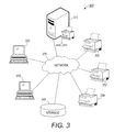
- FIG. 3 illustrates a block diagram of a network rendering system, which can be implemented in accordance with an embodiment
- FIG. 4 illustrates a detailed flow chart of operations illustrating logical operational steps of a method for automatically generating a helpdesk ticket when a rendering device possesses a series of customer resolvable events within a time period, in accordance with an embodiment
- FIG. 5 illustrates a timing diagram depicting change of an incident status with respect to a device status, in accordance with an embodiment
- FIG. 6 illustrates a timing diagram depicting change of an incident status with respect to a device status, in accordance with an embodiment.
- the disclosed method and system automatically generates a helpdesk ticket when a remote rendering device generates a series of customer resolvable events within a period of time.
- the system proactively manages the rendering device by identifying more serious conditions based on the frequency of occurrence, which is discussed in greater detail herein.
- Various computing environments may incorporate capabilities for supporting users accessing networks on which the rendering device(s) reside. The following discussion is intended to provide a brief, general description of suitable computing environments in which the method and system may be implemented. Although not required, the method and system will be described in the general context of computer-executable instructions, such as program modules, being executed by a single computer.
- program modules include routines, programs, objects, components, data structures, etc., that perform particular tasks or implement particular abstract data types.
- program modules include routines, programs, objects, components, data structures, etc., that perform particular tasks or implement particular abstract data types.
- program modules include routines, programs, objects, components, data structures, etc., that perform particular tasks or implement particular abstract data types.
- program modules include routines, programs, objects, components, data structures, etc., that perform particular tasks or implement particular abstract data types.
- program modules include routines, programs, objects, components, data structures, etc., that perform particular tasks or implement particular abstract data types.
- FIGS. 1-3 are provided as exemplary diagrams of data processing environments in which embodiments of the present invention may be implemented. It should be appreciated that FIGS. 1-3 are only exemplary and are not intended to assert or imply any limitation with regard to the environments in which aspects or embodiments of the present invention may be implemented. Many modifications to the depicted environments may be made without departing from the spirit and scope of the present invention.
- the present invention may be embodied in the context of a data-processing apparatus 100 comprising a central processor 101, a main memory 102, an input/output controller 103, a keyboard 104, a pointing device 105 (e.g., mouse, track ball, pen device, or the like), a display device 106, and a mass storage 107 (e.g., hard disk).
- a rendering device 108 may be included in the data-processing apparatus 100 as desired.
- the rendering device 108 may constitute, for example, a printer, a copier, fax machine, scanner, and/or other types of rendering components, depending upon design considerations.
- the various components of the data-processing apparatus 100 communicate through a system bus 110 or similar architecture.
- the data-processing apparatus 100 may be in some embodiments, a mobile computing device such as a Smartphone, a laptop computer, iPhone, etc.
- data-processing apparatus 100 may function as a desktop computer, server, and the like, depending upon design considerations.
- FIG. 2 illustrates a computer software system 150 for directing the operation of the data-processing apparatus 100 depicted in FIG. 1 .
- Software system 150 which is stored in system memory 102 and on disk memory 107, can include a kernel or operating system 151 and a shell or interface 153.
- One or more application programs, such as application software 152 may be "loaded” (i.e., transferred from storage 107 into memory 102) for execution by the data-processing apparatus 100.
- the data-processing apparatus 100 receives user commands and data through user interface 153; these inputs may then be acted upon by the data-processing apparatus 100 in accordance with instructions from operating module 151 and/or application module 152.
- module may refer to a collection of routines and data structures that perform a particular task or implements a particular abstract data type. Modules may be composed of two parts: an interface, which lists the constants, data types, variable, and routines that can be accessed by other modules or routines, and an implementation, which is typically private (accessible only to that module) and which includes source code that actually implements the routines in the module.
- the term module may also simply refer to an application, such as a computer program design to assist in the performance of a specific task, such as word processing, accounting, inventory management, etc.
- the interface 153 which is preferably a graphical user interface (GUI), also serves to display results, whereupon the user may supply additional inputs or terminate a given session.
- GUI graphical user interface
- operating system 151 and interface 153 can be implemented in the context of a "Windows" system. It can be appreciated, of course, that other types of systems are possible. For example, rather than a traditional "Windows" system, other operation systems, such as, Linux may also be employed with respect to operating system 151 and interface 153.
- Module 152 can be adapted for automatically generating the helpdesk ticket when the remote rendering device 108 possesses a series of customer resolvable issues. Module 152 can be adapted for effectively managing the helpdesk ticket associated with the rendering device 108.
- Application module 152 can include instructions, such as the various operations described herein with respect to the various components and modules described herein, such as, for example, the method 400 depicted in FIG. 4 .
- helpdesk generally refers to a dedicated internal organizational resource that provides technical or functional application problem-solving advice and follow up to system and/or product and/or product users.
- a helpdesk refers to technical support staff that assists in solving users' problems with hardware or software systems or refers such problems to those who can solve them.
- a "helpdesk” can also refer to so-called helpdesk type software, which can be uniquely modified to periodically contact product or service users, gather, record, and route problems immediately to designate problem solvers, register their commitment to a solution date, confirm their solution on that date, and then verify solution with the user reporting the problem.
- helpdesk software may refer to software applications for tracking problems with hardware and software and their solutions.
- FIG. 3 illustrates a block diagram of a network rendering system 300, which can be implemented in accordance with an embodiment. Note that in FIGS. 1-6 identical or similar blocks are generally indicated by identical reference numerals.
- Network rendering system 300 contains network 320, which is the medium used to provide communications links between various devices and computers connected together within network 320.
- Network 320 may include connections, such as, for example, wire, wireless communication links, fiber optic cables, and so forth.
- print server 310 can be connected to network 320 along with storage unit 340.
- end-user workstations 350 and 355 connect to network 320. These end-user workstations 350 and 355 may be, for example, personal computers or network computers.
- Data-processing system 100 depicted in FIG. 1 can be, for example, an end-user workstation such as end-user workstation 350 and 355.
- the end-user workstations 350 and 355 can be implemented as a helpdesk unit for operating a helpdesk which may be computerized and form part of the system 300 or alternatively may be external to the system and may comprise a human-operated help-desk.
- the helpdesk unit can be installed onsite i.e. in the customer environment. However, such helpdesk unit can also be offsite to provide the required functionality.
- data-processing system 100 can be implemented as a print server, such as print server 310, depending upon design considerations
- the printer server 310 can function as an operative communication medium between the user computer terminals 350 and 355 and the rendering devices 330, 332, 334, etc.
- Rendering devices 330, 332 and/or 334 can be distributed at various locations throughout a building, for example, or otherwise remotely located. While three rendering devices are shown by way of example, it is to be appreciated that any number of rendering devices may be linked to the network, such as two, four, six or more rendering devices.
- the rendering devices 330, 332 and/or 334 can be utilized to perform a rendering output function (e.g., printing, scanning, copying, faxing, etc) within a networked environment.
- the rendering device 108 described in greater detail herein are analogous or similar to rendering devices 330, 332 and/or 334.
- computer terminals 350 and 355 are also generally similar to one another.
- rendering device may refer to an apparatus or system such as a printer, scanner, fax machine, copy machine, etc., and/or a combination thereof.
- rendering devices 330, 332 and/or 334 may function as a MFD (Multifunction Device) capable of multiple rendering functions such as printing, copying, scanning, faxing, etc.
- MFD Multifunction Device
- rendering devices 330, 332 and 334 may be implemented with a single rendering function such as printing.
- rendering devices 330, 332 and 334 can be configured to provide multiple rendering functions, such as scanning, faxing, printing and copying.
- the printer server 310 is capable of receiving documents for rendering from the user computer terminals 350 and 355 and can select one or more destination network rendering devices 330, 332, 334 for routing the documents based on, for example, user preferences or other data.
- the computer terminals 350, 355, etc. can be, for example, any computing device capable of being integrated within a network, such as a PDA, personal computer, cellular telephone, point-of-sale terminal, server, etc.
- the rendering device 330, 332 and/or 334 can be located remotely with respect to each other, or alternatively, may be located locally with respect to each other, such as, for example, within a print shop or an office environment.
- the printer server 310 can automatically select the destination rendering devices 330, 332 and/or 334 for routing the rendering job requests.
- print server 310 provides data, such as boot files, operating system images, and applications to end-user workstations 350 and 355.
- End-user workstations 350 and 355 are clients to print server 310 in this example.
- Network rendering system 300 may include additional servers, end-user workstations, and other devices not shown. Specifically, end-user workstations may connect to any member of a network of servers, which provide equivalent content.
- FIG. 3 is intended as an example, and not as an architectural limitation of the disclosed embodiments.
- FIGS. 1-3 The following description is presented with respect to embodiments of the present invention, which may be embodied in the context of a data-processing system, such as, for example, the data-processing system 100, the network rendering system 300 and the network 320 depicted respectively FIGS. 1-3 .
- the present invention is not limited to any particular application or any particular environment. Instead, those skilled in the art will find that the system and methods of the present invention may be advantageously applied to a variety of system and application software, including database management systems, word processors, and the like.
- the present invention may be embodied on a variety of different platforms, including Macintosh, UNIX, LINUX, and the like. Therefore, the description of the exemplary embodiments, which follows, is for purposes of illustration and not considered a limitation.
- FIG. 4 illustrates a detailed flow chart of operations illustrating logical operational steps of a method 400 for automatically generating the helpdesk ticket when a remote rendering device 108 possesses a series of customer resolvable events within a short period of time, in accordance with an embodiment.
- the rendering device 108 can be checked for a fault condition with respect to the customer resolvable events such as, for example, paper jams and out of consumables, as illustrated at block 405.
- the device management module 152 continually checks the rendering device 108 for the fault condition and reports any issues associated with the rendering device 108 to the helpdesk unit 350.
- the device management module 152 can keep track of a previous error state and can reset a timer if the same error condition is detected within the specified time period.
- a notification can be sent to the helpdesk unit 350 and the helpdesk ticket can be initiated in an active state.
- the state associated with the helpdesk ticket can be continually updated, as depicted at block 425.
- FIG. 5 illustrates a timing diagram 500 depicting auto change of an incident status 530 with respect to a device status 510, in accordance with an embodiment.
- the timing diagram 500 illustrates working of the helpdesk unit 350 when the rendering device 108 does not move into the fault state for the defined number of times before a time period is reached.
- the timing diagram 500 depicts the interpretation of the operational status of the rendering device 108 via the use of a number of status polls 501-506.
- the status polls 501-506 indicate a particular instance at which the device status 510, a device management status 520, and the incident status 530 can be determined.
- the device management module 152 detects a problem in association with the rendering device 108 and starts tracking an issue with the rendering device 108, as shown at status poll 501.
- the device management module 152 checks the rendering device 108 to determine if the rendering device 108 is still in the fault state after a set period of time, as illustrated at status poll 502. As the rendering device 108 is still in the same fault state the device management module 152 sends a notification to the centralized helpdesk unit 350 and the helpdesk ticket can be created in the active state. Thereafter, as indicated at status poll 503, the rendering device 108 is no longer in the fault state and the helpdesk unit 350 moves the ticket into the passive state after sending notification to the helpdesk unit 350.
- the device management module 152 detects that the rendering device 108 back in the fault state at status poll 504 and the helpdesk unit 350 moves the ticket back into the active state after sending notification to the helpdesk unit 350. Again, after a number of status polls that is at status poll 505 the rendering device 108 is no longer in the fault state and the helpdesk unit 350 moves the ticket into the passive state after sending notification to the helpdesk unit 350. Thereafter, at status poll 506, the device management module 152 identifies that the device 108 has been out of the fault state for the defined period of time and the ticket can be deleted. The deletion can be notified to the helpdesk unit 350 and the ticket can be closed.
- FIG. 6 illustrates a timing diagram 600 depicting the auto change of the incident status 530 with respect to the device status 510, in accordance with an embodiment.
- the timing diagram 600 illustrates working of the helpdesk unit 350 when the rendering device 108 moves into the fault state for the defined number of times before the time period is reached.
- the device management module 152 detects that there is a problem with the rendering device 108 and starts tracking an issue with the rendering device 108.
- the device management module 152 checks the rendering device 108 to determine if the rendering device 108 is still in the fault state after a set period of time, as illustrated at status poll 602.
- the device management module 152 sends a notification to the centralized helpdesk unit 350 and the helpdesk ticket can be created in the active state.
- the rendering device 108 is no longer in the fault state, as indicated at status poll 603, and the helpdesk unit 350 moves the ticket into the passive state after sending notification to the helpdesk unit 350.
- the device management module 152 detects that the rendering device 108 back in the fault condition at status poll 604 and the helpdesk unit 350 moves the ticket back into the active state after sending notification to the helpdesk unit 350. Again, after a number of status polls that is at status poll 605 the rendering device 108 is no longer in the fault state and the helpdesk unit 350 moves the ticket into the passive state after sending notification to the helpdesk unit 350. Thereafter, at status poll 606, the device management module 152 detects that the rendering device 108 back in the fault condition and when the helpdesk unit 350 is notified it moves the ticket back into the active state.
- the device management module 152 detects that the rendering device 108 is no longer in the fault state and when the helpdesk unit 350 is notified it does not move the ticket into the passive state because the number of times the alert has occurred has been reached. Note that the defined number of alerts in this exemplary timing diagram 600 is three. After the device 108 has been out of the fault state for a defined period of time at status poll 608, the device management module 152 clears the knowledge associated with the issue and notifies the helpdesk unit 350 but the ticket remains in the active state.
- the customer resolvable issues can be tracked and notified to the helpdesk unit 350 without overwhelming the helpdesk unit 350 with the "no value add" incidents, which in turn reduces the cost of processing such low priority incidents.
- the centralized helpdesk unit 350 does not lose any information from the rendering device 108 as the incident can be updated each time the rendering device 108 changes the state.
- the occurrence of fault can be treated for assuring continued operation of the rendering device 108 with minimum disruption and notice of such fault occurrence can guide maintenance activity for providing uninterrupted device operation.
- Such a method and system enhance the performance of the rendering device 105 and extend the life expectancy.
Landscapes
- Business, Economics & Management (AREA)
- Engineering & Computer Science (AREA)
- Economics (AREA)
- Entrepreneurship & Innovation (AREA)
- Human Resources & Organizations (AREA)
- Marketing (AREA)
- Operations Research (AREA)
- Quality & Reliability (AREA)
- Strategic Management (AREA)
- Tourism & Hospitality (AREA)
- Physics & Mathematics (AREA)
- General Business, Economics & Management (AREA)
- General Physics & Mathematics (AREA)
- Theoretical Computer Science (AREA)
- Facsimiles In General (AREA)
- Debugging And Monitoring (AREA)
Abstract
A method and system for automatically generating a helpdesk ticket when a remote rendering device possesses a series of customer resolvable events within a time period. The helpdesk ticket can be moved into an active state (435) when an alert associated with the customer resolvable events is triggered and the ticket can be moved into a passive state (460) when the alert is no longer triggered for the predefined time period. The helpdesk ticket can be retained (450) in the active state if the fault condition detected for a defined number of times without being out of that state for the predefined time period. A device management module sends a notification indicative on each change of the state associated with the rendering device to a helpdesk unit. The device management module can also reset the time period between alerts if the problem occurs infrequently and the ticket can be automatically closed.
Description
- Embodiments are generally related to rendering devices, such as printers, scanners, multi-function devices, photocopy machines, and the like. Embodiments also relate in general to the field of computers and similar technologies, and in particular to software utilized in this field.
- Network printing systems are capable of interacting with an assemblage of varying rendering devices, client computers, servers, and other components that are connected to and communicate over a network. Rendering devices include components such as printers, scanners, faxes, copy machines, and so forth. Preventative maintenance can be performed with respect to such rendering devices to ensure that the device continues to function well with quality output and to protect the device from possible breakdowns while extending the lifetime of the device.
- Typically, preventative maintenance is ensured by employing a technician off site in order to manage and maintain the rendering devices. Problems (e.g., paper jams) associated with such rendering devices, may be resolved by a customer without having to actually contact a technician to service the rendering device. These types of customer resolvable issues are often not tracked as problems requiring a technician to be dispatched on-site, as they are assumed to represent normal operations, fully curable by the customer. In some cases, however, when the rendering device encounters a recurring issue, it can be assumed that such problems are due to a machine malfunction and that service should be dispatched. Organization "helpdesks" typically are not aware of such issues until members of the organization and/or other users, such as employees and customers, report the problem(s).
- Based on the foregoing it is believed that a need exists for an improved method and system for automatically generating a helpdesk ticket when a remote rendering device possesses a series of customer resolvable issues within a period of time. A need also exists for effectively managing the helpdesk ticket associated with the rendering device, as described in greater detail herein.
- The following summary is provided to facilitate an understanding of some of the innovative features unique to the present invention and is not intended to be a full description. A full appreciation of the various aspects of the embodiments disclosed herein can be gained by taking the entire specification, claims, drawings, and abstract as a whole.
- It is, therefore, one aspect of the embodiments to provide for an improved method and system for managing rendering devices, such as printers, scanners, multi-function devices, photocopy machines, and the like.
- It is another aspect of the embodiments to provide for an improved method and system for automatically generating a helpdesk ticket when a remote rendering device possesses a series of customer resolvable issues within a period of time.
- It is a further aspect of the embodiments to provide for an improved device management system and method for effectively managing the helpdesk ticket associated with the rendering device.
- The aforementioned aspects and other objectives and advantages can now be achieved as described herein. A method and system is disclosed for automatically generating a helpdesk ticket when a remote rendering device possesses a series of customer resolvable events within a time period. Customer resolvable events associated with the rendering device can be monitored and a helpdesk ticket initiated when one of the events persists for a predefined time period. The helpdesk ticket can be moved to an active state when an alert associated with the customer resolvable events is triggered and the ticket can be moved to a passive state when the alert is no longer triggered for the predefined time period. The helpdesk ticket can be retained in the active state if the fault condition detected is for a defined number of times without being out of that state for the predefined time period.
- A device management module can send a notification indicative of each change of state associated with the rendering device to a helpdesk unit. The device management module can also reset the time period between alerts if the problem occurs infrequently and the ticket may then be automatically closed. The device management module can track previous error states and reset a timer if the same error condition is detected within a specified time period. Each time the helpdesk unit receives an update from the device management module, the helpdesk can update the state of the ticket.
- Such an approach proactively manages the rendering device by identifying more serious conditions based on the frequency of occurrence. The centralized helpdesk unit does not lose any information from the rendering device as the incident can be updated each time the rendering device changes state. The occurrence of a fault can be treated to assure continued operation of the rendering device with minimum disruption. Notification of such fault occurrences can guide maintenance activity to ensure uninterrupted device operation. Such a method and system effectively enhances the performance of a rendering device and extends its life expectancy.
- The accompanying figures, in which like reference numerals refer to identical or functionally-similar elements throughout the separate views and which are incorporated in and form a part of the specification, further illustrate the present invention and, together with the detailed description of the invention, serve to explain the principles of the present invention.
-
FIG. 1 illustrates a schematic view of a data-processing system in which the present invention may be embodied; -
FIG. 2 illustrates a schematic view of a software system including an operating system, application software, and a user interface for carrying out an embodiment; -
FIG. 3 illustrates a block diagram of a network rendering system, which can be implemented in accordance with an embodiment; -
FIG. 4 illustrates a detailed flow chart of operations illustrating logical operational steps of a method for automatically generating a helpdesk ticket when a rendering device possesses a series of customer resolvable events within a time period, in accordance with an embodiment; -
FIG. 5 illustrates a timing diagram depicting change of an incident status with respect to a device status, in accordance with an embodiment; and -
FIG. 6 illustrates a timing diagram depicting change of an incident status with respect to a device status, in accordance with an embodiment. - The particular values and configurations discussed in these non-limiting examples can be varied and are cited merely to illustrate at least one embodiment and are not intended to limit the scope thereof.
- The disclosed method and system automatically generates a helpdesk ticket when a remote rendering device generates a series of customer resolvable events within a period of time. The system proactively manages the rendering device by identifying more serious conditions based on the frequency of occurrence, which is discussed in greater detail herein. Various computing environments may incorporate capabilities for supporting users accessing networks on which the rendering device(s) reside. The following discussion is intended to provide a brief, general description of suitable computing environments in which the method and system may be implemented. Although not required, the method and system will be described in the general context of computer-executable instructions, such as program modules, being executed by a single computer.
- Generally, program modules include routines, programs, objects, components, data structures, etc., that perform particular tasks or implement particular abstract data types. Moreover, those skilled in the art will appreciate that the method and system may be practiced with other computer system configurations, including hand-held devices, multiprocessor systems, microprocessor-based or programmable consumer electronics, networked PCs, minicomputers, mainframe computers, and the like.
-
FIGS. 1-3 are provided as exemplary diagrams of data processing environments in which embodiments of the present invention may be implemented. It should be appreciated thatFIGS. 1-3 are only exemplary and are not intended to assert or imply any limitation with regard to the environments in which aspects or embodiments of the present invention may be implemented. Many modifications to the depicted environments may be made without departing from the spirit and scope of the present invention. - As depicted in
FIG. 1 , the present invention may be embodied in the context of a data-processing apparatus 100 comprising acentral processor 101, amain memory 102, an input/output controller 103, akeyboard 104, a pointing device 105 (e.g., mouse, track ball, pen device, or the like), adisplay device 106, and a mass storage 107 (e.g., hard disk). Additional input/output devices, such as arendering device 108, may be included in the data-processing apparatus 100 as desired. Note that therendering device 108 may constitute, for example, a printer, a copier, fax machine, scanner, and/or other types of rendering components, depending upon design considerations. As illustrated, the various components of the data-processing apparatus 100 communicate through asystem bus 110 or similar architecture. It can be appreciated that the data-processing apparatus 100 may be in some embodiments, a mobile computing device such as a Smartphone, a laptop computer, iPhone, etc. In other embodiments, data-processing apparatus 100 may function as a desktop computer, server, and the like, depending upon design considerations. -
FIG. 2 illustrates acomputer software system 150 for directing the operation of the data-processing apparatus 100 depicted inFIG. 1 .Software system 150, which is stored insystem memory 102 and ondisk memory 107, can include a kernel oroperating system 151 and a shell orinterface 153. One or more application programs, such asapplication software 152, may be "loaded" (i.e., transferred fromstorage 107 into memory 102) for execution by the data-processing apparatus 100. The data-processing apparatus 100 receives user commands and data throughuser interface 153; these inputs may then be acted upon by the data-processing apparatus 100 in accordance with instructions from operatingmodule 151 and/orapplication module 152. - Note that the term module as utilized herein may refer to a collection of routines and data structures that perform a particular task or implements a particular abstract data type. Modules may be composed of two parts: an interface, which lists the constants, data types, variable, and routines that can be accessed by other modules or routines, and an implementation, which is typically private (accessible only to that module) and which includes source code that actually implements the routines in the module. The term module may also simply refer to an application, such as a computer program design to assist in the performance of a specific task, such as word processing, accounting, inventory management, etc.
- The
interface 153, which is preferably a graphical user interface (GUI), also serves to display results, whereupon the user may supply additional inputs or terminate a given session. In one possible embodiment,operating system 151 andinterface 153 can be implemented in the context of a "Windows" system. It can be appreciated, of course, that other types of systems are possible. For example, rather than a traditional "Windows" system, other operation systems, such as, Linux may also be employed with respect tooperating system 151 andinterface 153.Module 152 can be adapted for automatically generating the helpdesk ticket when theremote rendering device 108 possesses a series of customer resolvable issues.Module 152 can be adapted for effectively managing the helpdesk ticket associated with therendering device 108.Application module 152, on the other hand, can include instructions, such as the various operations described herein with respect to the various components and modules described herein, such as, for example, themethod 400 depicted inFIG. 4 . - Note that the term "helpdesk" as utilized herein generally refers to a dedicated internal organizational resource that provides technical or functional application problem-solving advice and follow up to system and/or product and/or product users. In this sense, a helpdesk refers to technical support staff that assists in solving users' problems with hardware or software systems or refers such problems to those who can solve them. A "helpdesk" can also refer to so-called helpdesk type software, which can be uniquely modified to periodically contact product or service users, gather, record, and route problems immediately to designate problem solvers, register their commitment to a solution date, confirm their solution on that date, and then verify solution with the user reporting the problem. Thus, helpdesk software may refer to software applications for tracking problems with hardware and software and their solutions.
-
FIG. 3 illustrates a block diagram of anetwork rendering system 300, which can be implemented in accordance with an embodiment. Note that inFIGS. 1-6 identical or similar blocks are generally indicated by identical reference numerals.Network rendering system 300 containsnetwork 320, which is the medium used to provide communications links between various devices and computers connected together withinnetwork 320.Network 320 may include connections, such as, for example, wire, wireless communication links, fiber optic cables, and so forth. In the depicted example,print server 310 can be connected to network 320 along withstorage unit 340. In addition, end-user workstations user workstations - Data-
processing system 100 depicted inFIG. 1 can be, for example, an end-user workstation such as end-user workstation user workstations system 300 or alternatively may be external to the system and may comprise a human-operated help-desk. The helpdesk unit can be installed onsite i.e. in the customer environment. However, such helpdesk unit can also be offsite to provide the required functionality. Alternatively, data-processing system 100 can be implemented as a print server, such asprint server 310, depending upon design considerations - The
printer server 310 can function as an operative communication medium between theuser computer terminals rendering devices Rendering devices rendering devices rendering device 108 described in greater detail herein are analogous or similar torendering devices computer terminals - Note that as utilized herein, the term "rendering device" may refer to an apparatus or system such as a printer, scanner, fax machine, copy machine, etc., and/or a combination thereof. Preferably,
rendering devices rendering devices rendering devices - Note that an example of an MFD device, which may be utilized to implement
rendering devices U.S. Patent No. 7,525,676 , entitled "System and method for controlling access to programming options of a multifunction device," which issued to Robert J. Pesar on April 28, 2009.U.S. Patent No. 7,525,676 , which is assigned to the Xerox Corporation of Norwalk, Connecticut, is incorporated herein by reference in its entirety. Another example of an MFD device, which may be utilized to implementrendering devices U.S. Patent No. 7,474,428 , which issued to Morris-Jones, et al on January 6, 2009 and is entitled Multifunction device system using tags containing output information."U.S. Patent No. 7,474,428 is also assigned to the Xerox Corporation of Norwalk, Connecticut, and is incorporated herein by reference in its entirety. An additional example of an MFD device and/or system, which may be utilized to implement rendering devices, 330, 332, 334, etc., is disclosed inU.S. Patent No. 5,920,405 , entitled "Multifunction device with printer/facsimile contention selection."U.S. Patent No. 5,920,405 , which issued to McIntyre, et al on July 6, 1999 and is assigned to the Xerox Corporation of Norwalk, Connecticut, is also incorporated herein by reference in its entirety. - The
printer server 310 is capable of receiving documents for rendering from theuser computer terminals network rendering devices computer terminals rendering device printer server 310 can automatically select thedestination rendering devices - In the depicted example,
print server 310 provides data, such as boot files, operating system images, and applications to end-user workstations user workstations server 310 in this example.Network rendering system 300 may include additional servers, end-user workstations, and other devices not shown. Specifically, end-user workstations may connect to any member of a network of servers, which provide equivalent content.FIG. 3 is intended as an example, and not as an architectural limitation of the disclosed embodiments. - The following description is presented with respect to embodiments of the present invention, which may be embodied in the context of a data-processing system, such as, for example, the data-
processing system 100, thenetwork rendering system 300 and thenetwork 320 depicted respectivelyFIGS. 1-3 . The present invention, however, is not limited to any particular application or any particular environment. Instead, those skilled in the art will find that the system and methods of the present invention may be advantageously applied to a variety of system and application software, including database management systems, word processors, and the like. Moreover, the present invention may be embodied on a variety of different platforms, including Macintosh, UNIX, LINUX, and the like. Therefore, the description of the exemplary embodiments, which follows, is for purposes of illustration and not considered a limitation. -
FIG. 4 illustrates a detailed flow chart of operations illustrating logical operational steps of amethod 400 for automatically generating the helpdesk ticket when aremote rendering device 108 possesses a series of customer resolvable events within a short period of time, in accordance with an embodiment. Again as reminder, inFIGS. 1-6 identical or similar elements and components are generally indicated by identical reference numerals. Therendering device 108 can be checked for a fault condition with respect to the customer resolvable events such as, for example, paper jams and out of consumables, as illustrated atblock 405. Thedevice management module 152 continually checks therendering device 108 for the fault condition and reports any issues associated with therendering device 108 to thehelpdesk unit 350. - A determination can be made whether the fault is found, as depicted at
block 410. If the fault is found the issue occurred in association with therendering device 108 can be tracked, as shown atblock 415. Otherwise, the process can be continued fromblock 405. Thedevice management module 152 can keep track of a previous error state and can reset a timer if the same error condition is detected within the specified time period. Next, as illustrated atblock 420, a notification can be sent to thehelpdesk unit 350 and the helpdesk ticket can be initiated in an active state. The state associated with the helpdesk ticket can be continually updated, as depicted atblock 425. - Thereafter, as illustrated at
block 430, a determination can be made whether therendering device 108 is still in the fault state. If therendering device 108 is in fault state the helpdesk ticket can be moved into the active state, as illustrated atblock 435. The number of active alerts can then be counted, as depicted atblock 440. A further determination can be made whether the number of alerts is exceeded, as indicated atblock 445. If the number of alerts are exceeded the ticket can be maintained in the active state, as illustrated atblock 450. Thereafter, the helpdesk ticket can be closed, as depicted atblock 455. Otherwise, the process can be continued fromblock 425. If the fault state does not occur the helpdesk ticket can be moved into a passive state, as shown atblock 460. Another determination can be made whether the time period exceeds the predefined time period, as illustrated atblock 465. If the time period exceeds, the helpdesk ticket can be closed, as depicted atblock 455. Otherwise the process can be continued fromblock 425. -
FIG. 5 illustrates a timing diagram 500 depicting auto change of anincident status 530 with respect to adevice status 510, in accordance with an embodiment. The timing diagram 500 illustrates working of thehelpdesk unit 350 when therendering device 108 does not move into the fault state for the defined number of times before a time period is reached. The timing diagram 500 depicts the interpretation of the operational status of therendering device 108 via the use of a number of status polls 501-506. The status polls 501-506 indicate a particular instance at which thedevice status 510, adevice management status 520, and theincident status 530 can be determined. - The
device management module 152 detects a problem in association with therendering device 108 and starts tracking an issue with therendering device 108, as shown atstatus poll 501. Thedevice management module 152 checks therendering device 108 to determine if therendering device 108 is still in the fault state after a set period of time, as illustrated atstatus poll 502. As therendering device 108 is still in the same fault state thedevice management module 152 sends a notification to thecentralized helpdesk unit 350 and the helpdesk ticket can be created in the active state. Thereafter, as indicated atstatus poll 503, therendering device 108 is no longer in the fault state and thehelpdesk unit 350 moves the ticket into the passive state after sending notification to thehelpdesk unit 350. - Next, the
device management module 152 detects that therendering device 108 back in the fault state atstatus poll 504 and thehelpdesk unit 350 moves the ticket back into the active state after sending notification to thehelpdesk unit 350. Again, after a number of status polls that is atstatus poll 505 therendering device 108 is no longer in the fault state and thehelpdesk unit 350 moves the ticket into the passive state after sending notification to thehelpdesk unit 350. Thereafter, atstatus poll 506, thedevice management module 152 identifies that thedevice 108 has been out of the fault state for the defined period of time and the ticket can be deleted. The deletion can be notified to thehelpdesk unit 350 and the ticket can be closed. -
FIG. 6 illustrates a timing diagram 600 depicting the auto change of theincident status 530 with respect to thedevice status 510, in accordance with an embodiment. The timing diagram 600 illustrates working of thehelpdesk unit 350 when therendering device 108 moves into the fault state for the defined number of times before the time period is reached. Initially, atstatus poll 601, thedevice management module 152 detects that there is a problem with therendering device 108 and starts tracking an issue with therendering device 108. Thedevice management module 152 checks therendering device 108 to determine if therendering device 108 is still in the fault state after a set period of time, as illustrated atstatus poll 602. As therendering device 108 is still in the same fault state thedevice management module 152 sends a notification to thecentralized helpdesk unit 350 and the helpdesk ticket can be created in the active state. Therendering device 108 is no longer in the fault state, as indicated atstatus poll 603, and thehelpdesk unit 350 moves the ticket into the passive state after sending notification to thehelpdesk unit 350. - Next, the
device management module 152 detects that therendering device 108 back in the fault condition atstatus poll 604 and thehelpdesk unit 350 moves the ticket back into the active state after sending notification to thehelpdesk unit 350. Again, after a number of status polls that is atstatus poll 605 therendering device 108 is no longer in the fault state and thehelpdesk unit 350 moves the ticket into the passive state after sending notification to thehelpdesk unit 350. Thereafter, atstatus poll 606, thedevice management module 152 detects that therendering device 108 back in the fault condition and when thehelpdesk unit 350 is notified it moves the ticket back into the active state. - Thereafter, at the
status poll 607 thedevice management module 152 detects that therendering device 108 is no longer in the fault state and when thehelpdesk unit 350 is notified it does not move the ticket into the passive state because the number of times the alert has occurred has been reached. Note that the defined number of alerts in this exemplary timing diagram 600 is three. After thedevice 108 has been out of the fault state for a defined period of time atstatus poll 608, thedevice management module 152 clears the knowledge associated with the issue and notifies thehelpdesk unit 350 but the ticket remains in the active state. - The customer resolvable issues can be tracked and notified to the
helpdesk unit 350 without overwhelming thehelpdesk unit 350 with the "no value add" incidents, which in turn reduces the cost of processing such low priority incidents. Thecentralized helpdesk unit 350 does not lose any information from therendering device 108 as the incident can be updated each time therendering device 108 changes the state. The occurrence of fault can be treated for assuring continued operation of therendering device 108 with minimum disruption and notice of such fault occurrence can guide maintenance activity for providing uninterrupted device operation. Such a method and system enhance the performance of therendering device 105 and extend the life expectancy.
Claims (14)
- A method, comprising:automatically generating a helpdesk ticket when a fault condition with respect to a plurality of customer resolvable events associated with a rendering device occurs within a predefined time period; andupdating an incident state associated with said helpdesk ticket in accordance with an update from a device management module wherein said device management module generates a notification indicative with respect to each change of said incident state associated with said rendering device in order to remotely maintain and manage said rendering device.
- The method of claim 1, wherein updating said incident state associated with said helpdesk ticket further comprises:automatically placing said helpdesk ticket into an active state, in response to triggering of an alert with respect to said fault condition associated with said plurality of customer resolvable events.
- The method of claim 2, wherein updating said incident state associated with said helpdesk ticket further comprises:automatically placing said helpdesk ticket into a passive state when said alert with respect to said fault condition is no longer triggered for said predefined time period.
- The method of claim 2 or claim 3, wherein updating said incident state associated with said helpdesk ticket further comprises:maintaining said helpdesk ticket in said active state, if said fault condition is detectable for a predefined number of instances without leaving said incident state during said predefined time period.
- The method of any of the preceding claims, further comprising monitoring said plurality of customer resolvable events associated with said rendering device in order to thereby initiate said helpdesk ticket when said plurality of customer resolvable events persists for said predefined time period.
- The method of any of the preceding claims, further comprising deleting said helpdesk ticket if said fault condition does not reoccur within said predefined time period.
- The method of any of the preceding claims, further comprising switching said helpdesk ticket to said active state if said fault condition reoccurs within said predefined time period.
- The method of any of the preceding claims, further comprising resetting said predefined time period between said alert if said plurality of customer resolvable events happens infrequently in order to thereby automatically close said helpdesk ticket.
- A system, comprising:a processor;a data bus coupled to said processor; anda computer-usable medium embodying computer code, said computer-usable medium being coupled to said data bus, said computer program code comprising instructions executable by said processor and configured forautomatically generating a helpdesk ticket when a fault condition with respect to a plurality of customer resolvable events associated with a rendering device occurs within a predefined time period; andupdating an incident state associated with said helpdesk ticket in accordance with an update from a device management module wherein said device management module generates a notification indicative with respect to each change of said incident state associated with said rendering device in order to remotely maintain and manage said rendering device.
- The system of any of the preceding claims, wherein said instructions are further configured for carrying out a method according to any of claims 1 to 8.
- A computer-usable medium embodying computer program code, said computer program code comprising computer executable instructions configured for:automatically generating a helpdesk ticket when a fault condition with respect to a plurality of customer resolvable events associated with a rendering device occurs within a predefined time period; andupdating an incident state associated with said helpdesk ticket in accordance with an update from a device management module wherein said device management module generates a notification indicative with respect to each change of said incident state associated with said rendering device in order to remotely maintain and manage said rendering device.
- The computer-usable medium of claim 11, wherein said embodied computer program code further comprises computer executable instructions configured for automatically placing said helpdesk ticket into an active state, in response to triggering of an alert with respect to said fault condition associated with said plurality of customer resolvable events;
- The computer-usable medium of claim 12, wherein said embodied computer program code further comprises computer executable instructions configured for automatically placing said helpdesk ticket into a passive state when said alert with respect to said fault condition is no longer triggered for said predefined time period.
- The computer-usable medium of claim 12 or claim 13, wherein said embodied computer program code further comprises computer executable instructions configured for maintaining said helpdesk ticket in said active state, if said fault condition is detectable for a predefined number of instances without leaving said incident state during said predefined time period.
Applications Claiming Priority (1)
| Application Number | Priority Date | Filing Date | Title |
|---|---|---|---|
| US12/570,889 US7996729B2 (en) | 2009-09-30 | 2009-09-30 | Method and system for maintenance of network rendering devices |
Publications (1)
| Publication Number | Publication Date |
|---|---|
| EP2328121A1 true EP2328121A1 (en) | 2011-06-01 |
Family
ID=43618107
Family Applications (1)
| Application Number | Title | Priority Date | Filing Date |
|---|---|---|---|
| EP10177551A Withdrawn EP2328121A1 (en) | 2009-09-30 | 2010-09-20 | Method and system for maintenance of network rendering devices |
Country Status (2)
| Country | Link |
|---|---|
| US (1) | US7996729B2 (en) |
| EP (1) | EP2328121A1 (en) |
Cited By (1)
| Publication number | Priority date | Publication date | Assignee | Title |
|---|---|---|---|---|
| WO2024161320A1 (en) * | 2023-01-31 | 2024-08-08 | Jio Platforms Limited | System and method for alarm categorization |
Families Citing this family (3)
| Publication number | Priority date | Publication date | Assignee | Title |
|---|---|---|---|---|
| US8266072B2 (en) * | 2009-04-22 | 2012-09-11 | Bank Of America Corporation | Incident communication interface for the knowledge management system |
| DE102013006351A1 (en) * | 2013-04-12 | 2014-10-30 | Unify Gmbh & Co. Kg | Method and device for managing a call to a call center |
| US10257055B2 (en) * | 2015-10-07 | 2019-04-09 | International Business Machines Corporation | Search for a ticket relevant to a current ticket |
Citations (4)
| Publication number | Priority date | Publication date | Assignee | Title |
|---|---|---|---|---|
| US5920405A (en) | 1995-03-10 | 1999-07-06 | Xerox Corporation | Multifunction device with printer/facsimile contention selection |
| US7343105B2 (en) * | 2004-06-30 | 2008-03-11 | Ricoh Company, Ltd. | Image forming apparatus and control method of image forming apparatus with operation based upon down event occurrences |
| US7474428B2 (en) | 2003-10-14 | 2009-01-06 | Xerox Corporation | Multifunction device system using tags containing output information |
| US7525676B2 (en) | 2005-04-20 | 2009-04-28 | Xerox Corporation | System and method for controlling access to programming options of a multifunction device |
Family Cites Families (28)
| Publication number | Priority date | Publication date | Assignee | Title |
|---|---|---|---|---|
| JP3127716B2 (en) * | 1994-06-02 | 2001-01-29 | セイコーエプソン株式会社 | Printer |
| US6006016A (en) * | 1994-11-10 | 1999-12-21 | Bay Networks, Inc. | Network fault correlation |
| JPH0950156A (en) * | 1995-08-07 | 1997-02-18 | Ricoh Co Ltd | Image forming apparatus and service system thereof |
| JPH11161451A (en) * | 1997-09-26 | 1999-06-18 | Hitachi Koki Co Ltd | Printing system |
| US6445774B1 (en) * | 1997-11-17 | 2002-09-03 | Mci Communications Corporation | System for automated workflow in a network management and operations system |
| JP3065053B2 (en) * | 1998-01-06 | 2000-07-12 | セイコーエプソン株式会社 | Device monitoring system, local monitoring device, integrated monitoring device, device monitoring method, and computer-readable medium storing program |
| US6901530B2 (en) * | 2000-08-01 | 2005-05-31 | Qwest Communications International, Inc. | Proactive repair process in the xDSL network (with a VDSL focus) |
| US7382474B2 (en) * | 2001-09-05 | 2008-06-03 | Minolta Co., Ltd. | Printer management method and management system |
| US6587647B1 (en) * | 2001-10-31 | 2003-07-01 | Ricoh Co., Ltd. | Method and system of remote monitoring of image forming apparatus |
| US6883119B1 (en) * | 2001-11-05 | 2005-04-19 | At&T Corp. | Methods of proactive network maintenance by automatic creation of trouble tickets |
| US7200613B2 (en) * | 2001-11-09 | 2007-04-03 | Xerox Corporation | Asset management system for network-based and non-network-based assets and information |
| US7017085B2 (en) * | 2002-05-30 | 2006-03-21 | Capital One Financial Corporation | Systems and methods for remote tracking of reboot status |
| US7131032B2 (en) * | 2003-03-13 | 2006-10-31 | Sun Microsystems, Inc. | Method, system, and article of manufacture for fault determination |
| US7006603B2 (en) * | 2003-03-14 | 2006-02-28 | Bellsouth Intellectual Property Corporation | Systems, methods and computer program products for automatically pushing a status change message as a result of repair services that are performed on a public switched telephone network (PSTN) |
| US7355758B2 (en) * | 2003-06-12 | 2008-04-08 | At&T Delaware Intellectual Property, Inc. | Automated facsimile monitoring and displaying methods and related systems |
| US7266734B2 (en) * | 2003-08-14 | 2007-09-04 | International Business Machines Corporation | Generation of problem tickets for a computer system |
| US20050081118A1 (en) * | 2003-10-10 | 2005-04-14 | International Business Machines Corporation; | System and method of generating trouble tickets to document computer failures |
| US7818631B1 (en) * | 2004-04-30 | 2010-10-19 | Sprint Communications Company L.P. | Method and system for automatically generating network trouble tickets |
| US7409594B2 (en) * | 2004-07-06 | 2008-08-05 | Intel Corporation | System and method to detect errors and predict potential failures |
| JP4455411B2 (en) * | 2004-08-06 | 2010-04-21 | キヤノン株式会社 | Information processing apparatus, information notification method thereof, and control program |
| JP4125274B2 (en) * | 2004-08-26 | 2008-07-30 | キヤノン株式会社 | Image input / output device, information processing method, computer-readable storage medium storing program, and program |
| US20060064481A1 (en) * | 2004-09-17 | 2006-03-23 | Anthony Baron | Methods for service monitoring and control |
| US20070150812A1 (en) * | 2005-12-23 | 2007-06-28 | Eazypaper Inc. | User support system integrating FAQ and helpdesk features |
| US8560948B2 (en) * | 2005-12-23 | 2013-10-15 | Michael Hu | User support system integrating FAQ and helpdesk features and FAQ maintenance capabilities |
| US7949740B2 (en) * | 2007-04-04 | 2011-05-24 | Xerox Corporation | Methods and systems for prioritized servicing or maintenance of networked printers |
| US9329822B2 (en) * | 2007-04-04 | 2016-05-03 | Xerox Corporation | Methods and apparatus for improved operation of networked printing system |
| US8902450B2 (en) * | 2007-04-04 | 2014-12-02 | Xerox Corporation | Methods and systems for soft failure detection for networked printers |
| US8205116B2 (en) * | 2009-02-18 | 2012-06-19 | At&T Intellectual Property I, L.P. | Common chronics resolution management |
-
2009
- 2009-09-30 US US12/570,889 patent/US7996729B2/en not_active Expired - Fee Related
-
2010
- 2010-09-20 EP EP10177551A patent/EP2328121A1/en not_active Withdrawn
Patent Citations (4)
| Publication number | Priority date | Publication date | Assignee | Title |
|---|---|---|---|---|
| US5920405A (en) | 1995-03-10 | 1999-07-06 | Xerox Corporation | Multifunction device with printer/facsimile contention selection |
| US7474428B2 (en) | 2003-10-14 | 2009-01-06 | Xerox Corporation | Multifunction device system using tags containing output information |
| US7343105B2 (en) * | 2004-06-30 | 2008-03-11 | Ricoh Company, Ltd. | Image forming apparatus and control method of image forming apparatus with operation based upon down event occurrences |
| US7525676B2 (en) | 2005-04-20 | 2009-04-28 | Xerox Corporation | System and method for controlling access to programming options of a multifunction device |
Non-Patent Citations (1)
| Title |
|---|
| "STATEMENT IN ACCORDANCE WITH THE NOTICE FROM THE EUROPEAN PATENT OFFICE DATED 1 OCTOBER 2007 CONCERNING BUSINESS METHODS - EPC / ERKLAERUNG GEMAESS DER MITTEILUNG DES EUROPAEISCHEN PATENTAMTS VOM 1.OKTOBER 2007 UEBER GESCHAEFTSMETHODEN - EPU / DECLARATION CONFORMEMENT AU COMMUNIQUE DE L'OFFICE EUROP", 20071101, 1 November 2007 (2007-11-01), XP002456252 * |
Cited By (1)
| Publication number | Priority date | Publication date | Assignee | Title |
|---|---|---|---|---|
| WO2024161320A1 (en) * | 2023-01-31 | 2024-08-08 | Jio Platforms Limited | System and method for alarm categorization |
Also Published As
| Publication number | Publication date |
|---|---|
| US20110078514A1 (en) | 2011-03-31 |
| US7996729B2 (en) | 2011-08-09 |
Similar Documents
| Publication | Publication Date | Title |
|---|---|---|
| EP2492812B1 (en) | Method and sytem for managing deferred alert notifications | |
| US8312324B2 (en) | Remote diagnostic system and method based on device data classification | |
| US8938650B2 (en) | Error report management | |
| US20190278529A1 (en) | System and method for machine learning optimization of human resource scheduling for device repair visits | |
| JP6460932B2 (en) | Image processing apparatus, system, image processing apparatus control method, system control method, and program | |
| US8738966B2 (en) | Change management system and method | |
| KR20100031574A (en) | Automatically managing system downtime in a computer network | |
| US11625208B2 (en) | Portable printer settings system | |
| US20120221954A1 (en) | Display filtering device management system | |
| US20140325517A1 (en) | Server system, method for controlling the same, and program for executing parallel distributed processing | |
| CN101442431A (en) | System and method for threshold-based notification of document processing device status | |
| KR102139058B1 (en) | Cloud computing system for zero client device using cloud server having device for managing server and local server | |
| US7996729B2 (en) | Method and system for maintenance of network rendering devices | |
| US11048496B1 (en) | Firmware upgrade system for printing devices using failure rate | |
| US20180241637A1 (en) | System and method for predictive maintenance | |
| CN102195808A (en) | Device management apparatus and device management method | |
| JP2017194954A5 (en) | ||
| JP2017187906A (en) | System, and method for controlling system | |
| EP3816784B1 (en) | System and method for monitoring, recommending and updating multifunction peripherals via a handheld device | |
| JP2012043119A (en) | Document management system, information processor, document management method, monitoring program and recording medium | |
| US20250097358A1 (en) | System and method for multifunction peripheral fleet management | |
| US10963195B1 (en) | Firmware upgrade system and methods for printing devices | |
| JP2009098755A (en) | Device management device, device management method and device management program | |
| WO2019241199A1 (en) | System and method for predictive maintenance of networked devices | |
| JP2016177766A (en) | System and operation information holding method |
Legal Events
| Date | Code | Title | Description |
|---|---|---|---|
| PUAI | Public reference made under article 153(3) epc to a published international application that has entered the european phase |
Free format text: ORIGINAL CODE: 0009012 |
|
| AK | Designated contracting states |
Kind code of ref document: A1 Designated state(s): AL AT BE BG CH CY CZ DE DK EE ES FI FR GB GR HR HU IE IS IT LI LT LU LV MC MK MT NL NO PL PT RO SE SI SK SM TR |
|
| AX | Request for extension of the european patent |
Extension state: BA ME RS |
|
| 17P | Request for examination filed |
Effective date: 20111201 |
|
| 17Q | First examination report despatched |
Effective date: 20160520 |
|
| STAA | Information on the status of an ep patent application or granted ep patent |
Free format text: STATUS: THE APPLICATION IS DEEMED TO BE WITHDRAWN |
|
| 18D | Application deemed to be withdrawn |
Effective date: 20161001 |