EP2327965A1 - Flow measuring device - Google Patents
Flow measuring device Download PDFInfo
- Publication number
- EP2327965A1 EP2327965A1 EP09809480A EP09809480A EP2327965A1 EP 2327965 A1 EP2327965 A1 EP 2327965A1 EP 09809480 A EP09809480 A EP 09809480A EP 09809480 A EP09809480 A EP 09809480A EP 2327965 A1 EP2327965 A1 EP 2327965A1
- Authority
- EP
- European Patent Office
- Prior art keywords
- flow passage
- flow
- auxiliary
- detection
- passages
- Prior art date
- Legal status (The legal status is an assumption and is not a legal conclusion. Google has not performed a legal analysis and makes no representation as to the accuracy of the status listed.)
- Granted
Links
Images







Classifications
-
- G—PHYSICS
- G01—MEASURING; TESTING
- G01F—MEASURING VOLUME, VOLUME FLOW, MASS FLOW OR LIQUID LEVEL; METERING BY VOLUME
- G01F1/00—Measuring the volume flow or mass flow of fluid or fluent solid material wherein the fluid passes through a meter in a continuous flow
- G01F1/68—Measuring the volume flow or mass flow of fluid or fluent solid material wherein the fluid passes through a meter in a continuous flow by using thermal effects
- G01F1/684—Structural arrangements; Mounting of elements, e.g. in relation to fluid flow
-
- G—PHYSICS
- G01—MEASURING; TESTING
- G01F—MEASURING VOLUME, VOLUME FLOW, MASS FLOW OR LIQUID LEVEL; METERING BY VOLUME
- G01F1/00—Measuring the volume flow or mass flow of fluid or fluent solid material wherein the fluid passes through a meter in a continuous flow
- G01F1/68—Measuring the volume flow or mass flow of fluid or fluent solid material wherein the fluid passes through a meter in a continuous flow by using thermal effects
- G01F1/684—Structural arrangements; Mounting of elements, e.g. in relation to fluid flow
- G01F1/6842—Structural arrangements; Mounting of elements, e.g. in relation to fluid flow with means for influencing the fluid flow
-
- G—PHYSICS
- G01—MEASURING; TESTING
- G01F—MEASURING VOLUME, VOLUME FLOW, MASS FLOW OR LIQUID LEVEL; METERING BY VOLUME
- G01F1/00—Measuring the volume flow or mass flow of fluid or fluent solid material wherein the fluid passes through a meter in a continuous flow
- G01F1/68—Measuring the volume flow or mass flow of fluid or fluent solid material wherein the fluid passes through a meter in a continuous flow by using thermal effects
-
- G—PHYSICS
- G01—MEASURING; TESTING
- G01F—MEASURING VOLUME, VOLUME FLOW, MASS FLOW OR LIQUID LEVEL; METERING BY VOLUME
- G01F5/00—Measuring a proportion of the volume flow
Definitions
- the present invention relates to a flow rate measurement device for measuring a flow rate of a gas, for example to a flow rate measurement device used in medical instruments such as treatment equipment for sleep apnea syndrome, industrial instruments for monitoring an air flow rate in factories, use in instrument embedment, and the like.
- an auxiliary flow passage diverges from a main flow passage, flow speed of a gas flowing in the auxiliary flow passage is measured by a flow rate detection element, and a total flow rate is determined by a diversion ratio of the main flow passage and the auxiliary flow passage and the flow speed in the auxiliary flow passage.
- an orifice (not shown) is provided in a main flow passage 13
- an auxiliary flow passage 14 is provided on a main flow pipe 12 astride an outer peripheral surface of the main flow pipe 12 having the main flow passage 13.
- the auxiliary flow passage 14 has the following structure.
- introduction ports 15 are provided on both the left and right sides on the upstream side of the orifice
- discharge ports 16 are provided on both the left and right sides on the downstream side of the orifice.
- Upper ends of introduction flow passages 17 (introduction vertical grooves) extending upward from the introduction ports 15 and upper ends of discharge flow passages 18 (discharge vertical grooves) extending upward from the discharge ports 16 are connected to each other by first auxiliary flow passages 19 so as to communicate with each other.
- the upper ends of the left and right introduction flow passages 17 are connected to each other by a second auxiliary flow passage 20 so as to communicate with each other, the upper ends of the left and right discharged, flow passages 18 are connected to each other by another second auxiliary flow passage 21 so as to communicate with each other, and center parts of both the second auxiliary flow passages 20, 21 are connected to each other by a horizontal detection flow passage 22 so as to communicate with each other.
- a flow rate detection element (not shown) for measuring flow speed of a gas its provided in the detection flow passage 22.
- an orifice is arranged in a main flow passage, four introduction flow passages and four discharge flow passages forming an auxiliary flow passage diverge from the main flow passage respectively on the upstream side and the downstream side of the orifice, a gas introduced from the introduction flow passages is collected into one detection flow passage, deviation of flow speed distribution is averaged, and then flow speed of the gas is measured by flow rate detection element.
- a flow rate measurement device is not only used for measuring a flow rate of a dry gas like a gas meter for a city gas but also used in an environment where dew condensation water is easily generated or used together with an instrument storing a liquid.
- One example thereof is treatment equipment for sleep apnea syndrome used in examination and treatment of sleep apnea syndrome (Continuous Positive Airway Pressure).
- This equipment is to feed air by a mechanical power source such as a pump and a fan motor so as to ensure aspiration of a patient.
- the flow rate measurement device is used for monitoring a gas flow rate changed in accordance with a change in an aspiration state of the patient.
- a humidifier is connected to a flow passage in which the flow rate measurement device is provided, and is some cases, the gas containing water vapor generated by the humidifier is fed to a mask attached to the patient through a hosepipe.
- a flow rate measurement device having a bypass flow passage structure is used as the flow rate measurement device.
- the dew condensation water generated inside the flow rate measurement device may flow into a detection flow passage provided with a flow rate detection element, or water of the humidifier may flow into the detection flow passage.
- the flow rate detection element is exposed in the detection flow passage for measuring flow speed of the gas.
- the water flowing into the detection flow passage adheres onto the flow rate detection element, there is a fear that measurement precision of the flow rate detection element is lowered or the element itself is deteriorated.
- the water breaking into the detection flow passage remains in the detection flow passage, a section area of the detection flow passage is changed, so that the flow speed of the gas passing through the detection flow passage is increased, and a diversion ratio of main flow passage and the detection flow passage is also changed.
- the measurement precision of the flow rate measurement device is lowered.
- the detection flow passage is formed perpendicularly to the introduction flow passages or the discharge flow passages.
- the water easily further breaks into the detection flow passage.
- the flow rate measurement device 11 when the water passes through the vertically placed introduction flow passages or the vertically placed discharge flow passages from the upper side to the lower side, there is a high possibility that the water breaks into the detection flow passage.
- the introduction flow passages and the discharge flow passages are arranged in all directions of center of the main flow passage, a water discharge property due to gravity is unfavorable. Thus, once the water breaks into the introduction flow passages, the discharge flow passages, or the detection flow passage, the water is not easily discharged.
- the flow rate measurement device having the bypass flow passage structure is used in a state that the gas is in contact with the liquid or water vapor or used in a state that the main flow passage communicates with a point where the liquid is accumulated.
- the liquid flows into the detection flow passage of the flow rate measurement device due to an unanticipated affair, characteristics of the flow rate measurement device are influenced. Therefore, a flow rate measurement device having a structure that the gas can pass through the detection flow passage but the liquid does not easily break into the detection flow passages is desired.
- the present invention is achieved in consideration with such technological problems, and an object thereof is to provide a structure that a liquid does not easily adhere onto a flow rate detection element, and the liquid does not easily break into or remain in a detection flow passage in which the flow rate detection element is provided in a flow rate measurement device having a bypass flow passage structure for measuring a great flow rate.
- a flow rate measurement device includes a main flow pipe having a main flow passage through which a gas passes, an orifice for limiting a flow of the gas in the main flow passage, and an auxiliary flow passage block provided with an auxiliary flow passage having one end communicating with a pair of introduction ports opened in the main flow passage on the upstream side of the orifice and the other end communicating with pair of discharge ports opened in the main flow passage on the downstream side of the orifice, wherein the auxiliary flow passage includes a pair of introduction flow passages having upstream ends respectively communicating with the introduction ports, an upstream auxiliary flow passage having both ends respectively connected to downstream ends of the introduction flow passages, a pair of discharge flow passages having downstream ends respectively communicating with the discharge ports, a downstream auxiliary flow passage having both ends respectively connected to upstream ends of the discharge flow passages, and a detection flow passage having an upstream end connected to the upstream auxiliary flow passage and a downstream end connected to the downstream auxiliary flow passage, the detection flow passage including a
- the upstream end of the detection flow passage is positioned on the upstream side of the main flow passage relative to the both ends of the upstream auxiliary flow passage, and the downstream end of the detection flow passage is positioned on the downstream side of the main flow passage relative to the both ends of the downstream auxiliary flow passage.
- the upstream end of the detection flow passage is connected to the upstream auxiliary flow passage at a position away from the downstream ends of the introduction flow passages, and the downstream end of the detection flow passage is connected to downstream auxiliary flow passage at a position away from the upstream ends of the discharge flow passages.
- the upstream auxiliary flow passage or the downstream auxiliary flow passage is placed between the introduction flow passages or the discharge flow passages and the detection flow passage.
- a bottom surface of the upstream auxiliary flow passage is inclined so as to be lowered gradually from a point where the upstream auxiliary flow passage is connected to the detection flow passage toward the both ends respectively connected to the introduction flow passages.
- a bottom surface of the downstream auxiliary flow passage is inclined so as to be lowered gradually from a point where the downstream auxiliary flow passage is connected to the detection flow passage toward the both ends respectively connected to the discharge flow passages.
- side auxiliary flow passages respectively connecting the downstream ends of the introduction flow passages and the upstream ends of the discharge flow passages are provided, and ends of bottom surfaces of the side auxiliary flow passages are respectively lower than an end of a bottom surface of the upstream auxiliary flow passage or an end of a bottom surface of the upper auxiliary flow passage.
- the auxiliary flow passage has a symmetric structure relative to a plane passing through center of the flow rate detection element, the plane being perpendicular to the axial direction of the main flow passage.
- Fig. 3 is an exploded perspective view of a flow rate measurement device 41 according to the first embodiment.
- Fig. 4 is a partially-broken perspective view of a base member of the flow rate measurement device 41.
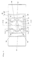
- Fig. 5 is a plan view of the base member.
- Fig. 6 is a sectional view by the line X-X of Fig. 5
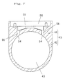
- Fig. 7 is a sectional view by the line Y-Y of Fig. 5 .
- the flow rate measurement device 41 of the first embodiment includes a synthetic resin bass member 45 formed by integrating an auxiliary flow passage block 44 for forming an auxiliary flow passage on an outer peripheral surface of a main flow pipe 42, an annular seal member 46 made of an insulating material such as rubber, and a circuit substrate 48 in which a flow rate detection element 47 is mounted on a lower surface.
- a recess portion 50 is formed on the substantially entire upper surface of the auxiliary flow passage block 44 having a box shape outer appearance.
- a seal groove 51 into which the seal member 46 is to be fitted is annularly provided on a bottom surface of the recess portion 50 so as to surround an auxiliary flow passage formation area (an area in which first auxiliary flow passages 58, second auxiliary flow passages 59, 60, and a detection flow passage 61 described later are formed) provided in the recess portion 50.
- Projections 52 for thermal caulking of the circuit substrate 48 protrude at four corners on the outer side or the seal groove.
- the substrate 48 is brought into the recess portion 50 in a state that the flow rate detection, element 47 is placed on the lower side, the projections 52 are inserted into holes 53 of the circuit substrate 48, and the projections 52 are thermally caulked onto the circuit substrate 48, so that the flow rate measurement device 41 is assembled.
- the circuit substrate 48 may be fixed to the base member 45 with using a method other than thermal caulking such as screws.
- An upper surface of the auxiliary flow passage block 44 is covered with a cover (not shown).
- the flow rate detection element 47 can be any type as long as the flow rate detection element can measure flow speed of the gas.
- a flow sensor having a heater and thermopiles can be used as the flow rate detection element 47.
- a cavity 72 is formed on an upper surface of a substrate 71 by etching, an insulating thin film 73 is extended on the cavity 72, and an edge of the insulating thin film 73 is held by the substrate 71.
- a heater 74 is formed bhy polysilicon in a center part of the insulating thin film 73, and thermopiles 75a, 75b are respectively provided on the upstream side and the downstream side of the heater 74.
- thermopiles 75a, 75b are formed by alternately connecting Al linear elements and polysilicon linear elements, and arranging the linear elements in a zigzag way.
- the thermopiles 75a, 75b are arranged symmetrically relative to the heater 74, so as to measure temperatures of symmetrical positions on the both sides of the heater 74.
- the reference numerals 76a, 76b denote electrode pads of the heater 74 and the thermopiles 75a, 75b.
- the heater 74 At the time of measurement, the heater 74 generates heat at a predetermined temperature, and predetermined temperature distribution ⁇ (a temperature gradient) is generated around the heater 74.
- the thermopiles 75a, 75b are symmetrically arranged.
- detected temperatures of both the thermopiles 75a, 75b are the same, and a temperature difference is zero.
- the heat of the heater 74 is transported to the downstream side, and the temperature distribution ⁇ is shifted to the downstream side.
- the detected temperature of the thermopile 75b on the downstream side is increased, and the detected temperature of the thermopile 75a on the upstream, side is lowered. Therefore, the flow speed of the gas can be calculated from the temperature difference between the detected temperatures of both the thermopiles 75a, 75b.
- the main flow pipe 42 has a main flow passage 43 through which a great flow rate of the gas passes.
- An orifice 49 (a flow limiter) is provided in a center part of the main flow passage 43 so as to partition the main flow passage 43.
- the orifice 49 is integrally formed on an inner peripheral surface of the main flow pipe 42, and as shown in Fig. 6 , formed by a circular portion having an inner circumferential diameter smaller than a diameter of the main flow passage 43, and a crisscross bar portion provided on the inner side of the circular portion. As shown in Fig.
- the circular portion of the orifice 49 protrudes on an inner peripheral surface of the main flow passage 43, so that the orifice 49 limits the flow of the gas passing through the main flow passage 43 and the bar portion gives resistance to the gas passing through the main flow passage 43.
- two introduction ports 54 are opened in an upper part of an inner surface of the main flow passage 43, and introduction flow passages 56 vertically pass through from the introduction ports 54 toward the interior of the recess portion 50.
- two discharge ports 55 are opened in the upper part of the inner surface of the main flow passage 43, and discharge flow passages 57 vertically pass through from the discharge ports 55 toward the interior of the recess portion 50.
- a horizontal first auxiliary flow passage 58 (a side auxiliary flow passage) extending in parallel to the axial direction of the main flow passage 43 is formed between an upper end of one of the introduction flow passages 56 and an upper end of one of the discharge flow passages 57.
- the introduction flow passage 56 and the discharge flow passage 57 communicate with each other through the first auxiliary flow passage 58.
- the other introduction flow passage 56 and the other discharge flow passage 57 communicate with each other through a horizontal first auxiliary flow passage 58.
- a second auxiliary flow passage 59 (an upstream auxiliary flow passage) extending in the width direction of the auxiliary flow passage block 44 is formed between the upper ends of the introduction flow passages 56 positioned on both the left and right sides.
- an end of a bottom surface of the second auxiliary flow passage 59 is placed at a higher position than bottom surfaces of the first auxiliary flow passages 58.
- the second auxiliary flow passage 59 has a V shape which is bent at center when seen from the vertically upper side, and the bottom surface of the second auxiliary flow passage 59 is inclined so as to be higher from both ends toward the center (refer to Fig. 7 ).
- a second auxiliary flow passage 60 (a downstream auxiliary flow passage) extending in the width direction of the auxiliary flow passage block 44 is formed between the upper ends of the discharge flow passages 57 positioned on the both sides.
- an end of a bottom surface of the second auxiliary flow passage 60 is placed at a higher position than the bottom surfaces of the first auxiliary flow passages 58.
- the second auxiliary flow passage 60 has a V shape which is bent at center when seen from the vertically upper side, and the bottom surface of the second auxiliary flow passage 60 is inclined so as to be higher from both ends toward the center.
- a straight detection flow passage 61 is formed between the center of the second auxiliary flow passage 59 positioned on the upstream side and the center of the second auxiliary flow passage 60 positioned on the downstream side.
- the second auxiliary flow passages 59, 60 communicate with each other through the detection flow passage 61.
- a measurement chamber 62 having large width is formed in a center part in the longitudinal direction of the detection flow passage 61.
- the flow rate detection element 47 mounted on the lower surface of the circuit substrate 48 is positioned on a ceiling surface of the measurement chamber 62.
- a bottom surface passing through the detection flow passage 61 from the center of the second auxiliary flow passage 59 to the center of the second auxiliary flow passage 60 is a horizontal surface.
- the bottom surface of the detection flow passage 61 is raised into a trapezoid shape in order to increase the flow speed of the gas.
- the second auxiliary flow passages 59, 60 are bent into a V shape, so that the centers of the second auxiliary flow passages 59, 60 are respectively away from the measurement chamber 62. Therefore, length of the detection flow passage 61 is longer than the first auxiliary flow passages 58. It should be noted that the second auxiliary flow passages 59, 60 and the detection flow passage 61 are formed into a groove shape with open upper surfaces, and openings of the upper surfaces are covered with the circuit substrate 48, so that the flow passages are closed.
- the measurement chamber 62 and the flow rate detection element 47 are positioned on the vertically upper side of center of the orifice 49.
- the auxiliary flow passage including the introduction ports 54, the introduction flow passages 56, the first auxiliary flow passages 58, the second auxiliary flow passage 59, the detection flow passage 61, the measurement chamber 62, the second auxiliary flow passage 60, the detection flow passages 57, and the discharge ports 55 has a left-right symmetrical structure relative to a vertical plane including the axis oaf the main flow passage 43, and also a symmetrical structure relative to a plane passing through center of the flow rate detection element 47 (or the center of the orifice 49), the plane being perpendicular to the axis of the main flow passage 43.
- the gas smoothly flows in the auxiliary flow passage.
- the base member 45 formed by integrating the main flow pipe 42, the orifice 49, and the auxiliary flow passage block 44 has the above structure.
- the introduction flow passages 56 and the discharge flow passages 57 are formed by vertical through holes
- the first auxiliary flow passages 58the second auxiliary flow passages 59, 60, the detection flow passage 61, and the measurement chamber 62 are all formed by recessed grooves.
- the base member can be integrally molded by one injection molding.
- a mold is formed by an upper mold for molding an upper outer peripheral surface of the main flow pipe 42 and the auxiliary flow passage block 44, a lower mold for molding a lower outer peripheral surface of the main flow pipe 42, a first supplementary mold for molding half of the main flow passage 43 and the orifice 49, and a second supplementary mold for molding the remaining half of the main flow passage 43 and the orifice 49.
- the upper mold and the lower mold are opened in the up and down direction, and the first and second supplementary molds are drawn in the horizontal direction.
- Fig. 9 is a view schematically showing the auxiliary flow passage including the introduction flow passages 56, the first auxiliary flow passages 58, the second auxiliary flow passage 59, the detection flow passage 61, the second auxiliary flow passage 60, and the discharge flow passages 57 (the flow rate measurement device 41 can be manufactured into a shape as in Fig. 9 in facet). With using the schematic view, the flow of the gas in the flow rate measurement device 41 will be described.
- the orifice 49 is provided in the main flow passage 43, the gas flowing in the main flow passage 43 receives the resistance by the orifice 49. Therefore, on the upstream, side of the orifice 49, pressure of the gas is higher than the downstream side, so that part of the gas easily flows from the Introduction ports 54 into the introduction flow passages 56.
- the gas When part of the gas passing through in the main flow passage 43 flows from the introduction ports 54 into the introduction flow passages 56, the gas is dividend into the first auxiliary flow passages 58 and the second auxiliary flow passage 59 at the upper ends of the introduction flow passages 56.
- the gas entering the first auxiliary flow passages 58 passes through the first auxiliary flow passages 58 to the discharge flow passages 57, returns from the discharge ports 55 to the main flow passage 43 again, and then flows in the main flow passage 43.
- the gas flows into the second auxiliary flow passage 59 from both ends, and the gas jointing in a center part of the second auxiliary flow passage 59 passes through in the detection flow passage 61.
- the measurement chamber 62 provided in the center part of the detection flow passage 61 has larger width than the detection flow passage 61 and lower height than the detection flow passage 61.
- the gas passing through the measurement chamber 62 passes through a surface of the flow rate detection element 47 while being thinly spread, so that the flow speed is detected.
- a flow rate of the gas passing through the main flow passage 43 is calculated from a diversion ratio of the main flow passage 43 and the detection flow passage 61, the flow speed detected by the flow rate detection element 47, and the like.
- the gas coming from the end of the detection flow passage 61 to the center of the second auxiliary flow passage 60 is divided into the left and right sides so as to pass through in the second auxiliary flow passage 60, returns to the main flow passage 43 again through the discharge flow passages 57, and then flows in the main flow passage 43.
- the diversion ratio of the main flow passage 43 and the detection flow passage 61 is set to be an appropriate value.
- the flow speed can be lowered down to a flow speed range suitable for measurement by the flow rate detection element 47 (a range in which an output is linear) in the measurement chamber 62. Therefore, the flow rate measurement device 41 capable of measuring a great flow rate can be downsized. Since the orifice 49 is provided in the main flow passage 43, the flow speed distribution of the gas on a section perpendicular to the axial direction of the main flow passage 43 can be homogenized. Thus, variation of the diversion ratio of the main flow passage 43 and the detection flow passage 61 is reduced, so that measurement precision can be improved.
- the first auxiliary flow passages 58 have a function of reducing the flow rate of the gas flowing in the detection flow passage 61 by bypassing the gas, and a function of optimizing the flow speed in the measurement chamber 62 by adjusting a section area of the first auxiliary flow passages 58. Furthermore, since the first auxiliary flow passages 58 are formed by providing recessed grooves on the upper surface of the auxiliary flow passage block 44, adjustment of the section area is easily performed due to a mold structure.
- this flow rate measurement device 41 has a structure by which the liquid does not easily break into the detection flow passage 61 for the above reasons, so that the detection flow passage 61 and the flow rate detection element 47 are not easily contaminated by the liquid.
- the liquid breaks into the introduction flow passages 56 from the introduction ports 54, and the liquid adheres onto wall surfaces of the introduction flow passages 56. At this time, there is a possibility that the liquid is blown up by the flow of the gas and brought into deep parts of the introduction flow passages 56.
- the end of the bottom surface of the second auxiliary flow passage 59 is higher than the bottom surfaces of the first auxiliary flow passages 58.
- the liquid reaching to the upper ends of the introduction flow passages 56 does not easily break into the side of the second auxiliary flow passage 59 but can easily break into the side of the first auxiliary flow passages 58.
- the liquid breaking into the first auxiliary flow passages 58 is discharged into the main flow passage 43 through the first auxiliary flow passages 58 and the discharge ports 55. Therefore, in this flow rate measurement device 41, since the bottom surfaces of the first auxiliary flow passages 58 are provided at lower positions than the bottom surfaces of the second auxiliary flow passages 59, 60, the liquid breaking into the introduction flow passages 56 does not easily reach to the detection flow passage 61.
- second auxiliary flow passages 20, 21 are straight.
- a detection flow passage 22 (refer to Fig. 2 ).
- the center parts of the second auxiliary flow passages 59, 60 connected to the detection flow passage 61 are bent so as to project toward the opposite sides of the detection flow passage 61. Therefore, at the time of carrying the instrument or the like, in a case where the instrument is overturned, the auxiliary flow passage lies an the side in a posture shown in Fig. 10 .
- the liquid obliquely flows down in the second auxiliary flow passages 59, 60 toward the end of the detection flow passage 61 on the upper side of the detection flow passage 61, flows in the direction of going away from the end of the detection flow passage 61 immediately before the end of the detection flow passage 61, and moves in the second auxiliary flow passages 59, 60 from the upper side to the lower side of the detection flow passage 61 while avoiding the end of the detection flow passage 61.
- the liquid does not easily break into the detection flow passage 61.
- the bottom surfaces of the second auxiliary flow passages 59, 60 are inclined, a flow passage section area is large in the both ends and the smallest in the centers in the second auxiliary flow passages 59, 60.
- the liquid flowing toward the centers of the second auxiliary flow passages 59, 60 is accelerated gradually toward the centers, so that the liquid further does not easily enter the detection flow passage 61.
- the liquid flowing down in the second auxiliary flow passages 59, 60 is discharged from the introduction ports 54 or the discharge ports 55.
- the second auxiliary flow passages 59, 60 are bent into a V shape. Thus, even in a case where the flow rate measurement device 41 is overturned, the liquid does not easily flow into the detection flow passage 61.
- the upper second auxiliary flow passage (here, the second auxiliary flow passage 59) has a reversed V shape when seen from the front side.
- the liquid entering here is discharged to the both sides along the second auxiliary flow passage 59 as shown by arrows in Fig. 11 , and further flows down to the lower side from the first auxiliary flow passages 58. Therefore, even when the liquid enters the second auxiliary flow passage 59, there is little fear that the liquid breaks into the detection flow passage 61.
- the liquid flowing down in the first auxiliary flow passages 58 is accumulated in the center of the lower second auxiliary flow passage (the second auxiliary flow passage 60).
- the liquid accumulated in the center of the second auxiliary flow passage 60 flows to the both ends by the inclination of the bottom surface of the second auxiliary flow passage 60, and is discharged from the discharge flow passages 57 to the main flow passage 43.
- the second auxiliary flow passages 59, 60 are bent into a V shape and the bottom surfaces of the second auxiliary flow passages 59, 60 are inclined. Thus, even in a case where the flow rate measurement device 41 is overturned, the liquid does not easily flow into the detection flow passage 61.
- the detection flow passage 61 and the flow rate element 47 are not easily contaminated by contact with the liquid. Particularly, even in a case where the flow rate measurement device is used in an instrument provided with a tank accumulating the liquid or the like, and even when the liquid remaining in the tank flows out at the time of carrying the instrument, the liquid does not easily flow into the detection flow passage 61. Furthermore, when the instrument is installed in a correct posture, the liquid flowing into the auxiliary flow passage can be promptly discharged to the main flow passage 43. Therefore, in this flow rate measurement device 41, deterioration of characteristics of the flow rate measurement device 41 can be suppressed even in an environment where the liquid is used.
- surface treatment is desirably performed so that maximum height of surface roughness is not more than 25 ⁇ m on surfaces of the auxiliary flow passage (particularly surfaces of the first auxiliary flow passages 58, the second auxiliary flow passages 59, 60, the detection flow passage 61, and the measurement chamber 62).
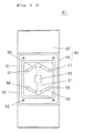
- Fig. 12 is a plan view of a base member 81 used in the flow rate measurement device according to a second embodiment of the present invention.
- the left and right first auxiliary flow passages 58 in the first embodiment are omitted, and the introduction ports 54 and the discharge ports 55 are not directly connected to each other.
- the flow rate in the detection flow passage 61 can be increased.
- the bottom surface of the measurement chamber 62 is not raised, and the bottom surface of the detection flow passage 61 is formed to be flat from one end to the other end.
- Fig. 13 is a sectional view of a flow rate measurement device 91 according to a third embodiment of the present invention.
- this flow rate measurement device 91 left and right symmetrical surfaces of the auxiliary flow passage are displaced from left and right symmetrical surfaces of the main flow passage 43.
- the two introduction ports 54 are provided at asymmetrical positions of the main flow passage 43, a function of averaging the flow speed of the measurement gas sampled from the introduction ports 54 is promoted.
Landscapes
- Physics & Mathematics (AREA)
- Fluid Mechanics (AREA)
- General Physics & Mathematics (AREA)
- Measuring Volume Flow (AREA)
Abstract
Description
- The present invention relates to a flow rate measurement device for measuring a flow rate of a gas, for example to a flow rate measurement device used in medical instruments such as treatment equipment for sleep apnea syndrome, industrial instruments for monitoring an air flow rate in factories, use in instrument embedment, and the like.
- In general, in a straight pipe type flow rate measurement device for directly measuring a great flow rate among flow rate measurement devices, there is a need for enlarging a diameter of a pipe in order to lower flow speed by a measurable area of a flow rate detection element. Thus, downsizing of the device is limited. In order to downsize the flow rate measurement device for measuring a great flow rate, in general, a flow rate measurement device having a bypass flow passage structure is proposed. In the flow rate measurement device having the bypass flow passage structure, an auxiliary flow passage diverges from a main flow passage, flow speed of a gas flowing in the auxiliary flow passage is measured by a flow rate detection element, and a total flow rate is determined by a diversion ratio of the main flow passage and the auxiliary flow passage and the flow speed in the auxiliary flow passage.
- However, in such a flow rate measurement device having the bypass flow passage structure, flow speed distribution on a vertical section in the main flow passage easily becomes inhomogeneous due to existence of the auxiliary flow passage. When the flow speed distribution in the main flow passage is inhomogeneous, the diversion ratio to the auxiliary flow passage becomes unstable. Thus, a precise total flow rate is not easily determined.
- A flow rate measurement device having a bypass flow passage structure for improving a decrease in measurement precision due to such inhomogeneity of the flow speed its shown in
Fig. 1 (refer to Patent Document 1). In this flowrate measurement device 11, an orifice (not shown) is provided in amain flow passage 13, and anauxiliary flow passage 14 is provided on amain flow pipe 12 astride an outer peripheral surface of themain flow pipe 12 having themain flow passage 13. - The
auxiliary flow passage 14 has the following structure. On an inner wall of themain flow passage 13,introduction ports 15 are provided on both the left and right sides on the upstream side of the orifice, anddischarge ports 16 are provided on both the left and right sides on the downstream side of the orifice. Upper ends of introduction flow passages 17 (introduction vertical grooves) extending upward from theintroduction ports 15 and upper ends of discharge flow passages 18 (discharge vertical grooves) extending upward from thedischarge ports 16 are connected to each other by firstauxiliary flow passages 19 so as to communicate with each other. The upper ends of the left and rightintroduction flow passages 17 are connected to each other by a secondauxiliary flow passage 20 so as to communicate with each other, the upper ends of the left and right discharged,flow passages 18 are connected to each other by another secondauxiliary flow passage 21 so as to communicate with each other, and center parts of both the secondauxiliary flow passages detection flow passage 22 so as to communicate with each other. A flow rate detection element (not shown) for measuring flow speed of a gas its provided in thedetection flow passage 22. - When the gas passes through the interior of the
main flow passage 13 of this flowrate measurement device 11, part of the gas flows from the introduction,ports 15 into theauxiliary flow passage 14, returns from thedischarge ports 16 to themain flow passage 13 through a route as shown by arrows inFig. 1 , and then flows in themain flow passage 13 again. At this time, the gas flowing into theintroduction flow passages 17 bifurcates and flows into the firstauxiliary flow passages 19 and the secondauxiliary flow passage 20, so that part of the gas flows into the secondauxiliary flow passage 20. The gas flowing into the secondauxiliary flow passage 20 from the left and right sides together flows into thedetection flow passage 22. The flow speed of the gas passing through thedetection flow passage 22 is measured, and a total flow rate is determined by a diversion ratio of themain flow passage 13 and thedetection flow passage 22, and the flow speed in thedetection flow passage 22. - Similarly, in a flow rate measurement device disclosed in
Patent Document 2, an orifice is arranged in a main flow passage, four introduction flow passages and four discharge flow passages forming an auxiliary flow passage diverge from the main flow passage respectively on the upstream side and the downstream side of the orifice, a gas introduced from the introduction flow passages is collected into one detection flow passage, deviation of flow speed distribution is averaged, and then flow speed of the gas is measured by flow rate detection element. -
- Patent Document 1: Japanese Patent No.
3870969 - Patent Document 2:
U.S. Patent No. 5,279,155 - A flow rate measurement device is not only used for measuring a flow rate of a dry gas like a gas meter for a city gas but also used in an environment where dew condensation water is easily generated or used together with an instrument storing a liquid.
- One example thereof is treatment equipment for sleep apnea syndrome used in examination and treatment of sleep apnea syndrome (Continuous Positive Airway Pressure). This equipment is to feed air by a mechanical power source such as a pump and a fan motor so as to ensure aspiration of a patient. The flow rate measurement device is used for monitoring a gas flow rate changed in accordance with a change in an aspiration state of the patient. In this treatment equipment, a humidifier is connected to a flow passage in which the flow rate measurement device is provided, and is some cases, the gas containing water vapor generated by the humidifier is fed to a mask attached to the patient through a hosepipe.
- In such equipment, a great flow rate of the gas has to be measured, and furthermore, downsizing is required, and the flow passages are required to have low pressure loss for using a small-power mechanical power source. Therefore, a flow rate measurement device having a bypass flow passage structure is used as the flow rate measurement device.
- However, in such a use, the dew condensation water generated inside the flow rate measurement device may flow into a detection flow passage provided with a flow rate detection element, or water of the humidifier may flow into the detection flow passage.
- The flow rate detection element is exposed in the detection flow passage for measuring flow speed of the gas. Thus, when the water flowing into the detection flow passage adheres onto the flow rate detection element, there is a fear that measurement precision of the flow rate detection element is lowered or the element itself is deteriorated. When the water does not adhere onto the flow rate detection element but the water breaking into the detection flow passage remains in the detection flow passage, a section area of the detection flow passage is changed, so that the flow speed of the gas passing through the detection flow passage is increased, and a diversion ratio of main flow passage and the detection flow passage is also changed. Thus, there is a problem that the measurement precision of the flow rate measurement device is lowered.
- In the conventional flow rate measurement device, measures against such problems are insufficient. Is the flow
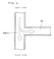
rate measurement device 11 described inPatent Document 1, as shown inFig. 1 , the horizontally arranged secondauxiliary flow passage detection flow passage 22 are perpendicularly crossing on a horizontal plane. Thus, once water flows into the secondauxiliary flow passage detection flow passage 22. At the time of carrying an instrument in which the flowrate measurement device 11 is built or the like, when the instrument is overturned and the flowrate measurement device 11 lies on the side, the secondauxiliary flow passage Fig. 2 . Thus, as shown by an arrow inFig. 2 , the water passes through the secondauxiliary flow passage detection flow passage 22. - In the flow rate measurement device described in
Patent Document 2 as well, the detection flow passage is formed perpendicularly to the introduction flow passages or the discharge flow passages. Thus, once the water flows into the introduction flow passages or the discharge flow passages, the water easily further breaks into the detection flow passage. As well as the case of the flow rate measurement device 11 (refer toFig. 2 ), when the water passes through the vertically placed introduction flow passages or the vertically placed discharge flow passages from the upper side to the lower side, there is a high possibility that the water breaks into the detection flow passage. Further, in the flow rate measurement device ofPatent Document 2, since the introduction flow passages and the discharge flow passages are arranged in all directions of center of the main flow passage, a water discharge property due to gravity is unfavorable. Thus, once the water breaks into the introduction flow passages, the discharge flow passages, or the detection flow passage, the water is not easily discharged. - As described above, the flow rate measurement device having the bypass flow passage structure is used in a state that the gas is in contact with the liquid or water vapor or used in a state that the main flow passage communicates with a point where the liquid is accumulated. When the liquid flows into the detection flow passage of the flow rate measurement device due to an unanticipated affair, characteristics of the flow rate measurement device are influenced. Therefore, a flow rate measurement device having a structure that the gas can pass through the detection flow passage but the liquid does not easily break into the detection flow passages is desired.
- The present invention is achieved in consideration with such technological problems, and an object thereof is to provide a structure that a liquid does not easily adhere onto a flow rate detection element, and the liquid does not easily break into or remain in a detection flow passage in which the flow rate detection element is provided in a flow rate measurement device having a bypass flow passage structure for measuring a great flow rate.
- In order to achieve such an object, a flow rate measurement device according to the present invention includes a main flow pipe having a main flow passage through which a gas passes, an orifice for limiting a flow of the gas in the main flow passage, and an auxiliary flow passage block provided with an auxiliary flow passage having one end communicating with a pair of introduction ports opened in the main flow passage on the upstream side of the orifice and the other end communicating with pair of discharge ports opened in the main flow passage on the downstream side of the orifice, wherein the auxiliary flow passage includes a pair of introduction flow passages having upstream ends respectively communicating with the introduction ports, an upstream auxiliary flow passage having both ends respectively connected to downstream ends of the introduction flow passages, a pair of discharge flow passages having downstream ends respectively communicating with the discharge ports, a downstream auxiliary flow passage having both ends respectively connected to upstream ends of the discharge flow passages, and a detection flow passage having an upstream end connected to the upstream auxiliary flow passage and a downstream end connected to the downstream auxiliary flow passage, the detection flow passage including a flow rate detection element, the upstream end of the detection flow passage is positioned on the upstream side of the main flow passage relative to the both ends of the upstream auxiliary flow passage, and the downstream end of the detection flow passage is positioned on the downstream side of the main flow passage relative to the both ends of the downstream auxiliary flow passage.
- With the flow rate measurement device of the present invention, the upstream end of the detection flow passage is positioned on the upstream side of the main flow passage relative to the both ends of the upstream auxiliary flow passage, and the downstream end of the detection flow passage is positioned on the downstream side of the main flow passage relative to the both ends of the downstream auxiliary flow passage. Thus, even when an instrument in which the flow rate measurement device is built falls down and the flow rate measurement device is vertically placed or lies on the side, a liquid does not easily breaks into the detection flow passage, so that the detection flow passage is not easily contaminated by the liquid and the liquid does not easily adhere onto the flow rate detection element. Therefore, even in a case where the flow rate measurement device is built in an instrument using the liquid, characteristics of the flow rate measurement device are not easily lowered even with the liquid breaking into the flow rate measurement, device.
- In an aspect of the flow rate measurement device according to the present invention, the upstream end of the detection flow passage is connected to the upstream auxiliary flow passage at a position away from the downstream ends of the introduction flow passages, and the downstream end of the detection flow passage is connected to downstream auxiliary flow passage at a position away from the upstream ends of the discharge flow passages. With such an aspect, the upstream auxiliary flow passage or the downstream auxiliary flow passage is placed between the introduction flow passages or the discharge flow passages and the detection flow passage. Thus, the liquid breaking into the introduction flow passages or the discharge flow passages can be prevented from directly flowing into the detection flow passage.
- In one of other aspects of the flow rate measurement device according to the present invention, a bottom surface of the upstream auxiliary flow passage is inclined so as to be lowered gradually from a point where the upstream auxiliary flow passage is connected to the detection flow passage toward the both ends respectively connected to the introduction flow passages. With such an aspect, the liquid breaking into the upstream auxiliary flow passage is discharged to the side of the introduction flow passages by inclination of the bottom surface of the upstream auxiliary flow passage. Thus, the liquid does not easily break into the detection flow passage.
- In further one of other aspects of the flow rate measurement device according to the present invention, a bottom surface of the downstream auxiliary flow passage is inclined so as to be lowered gradually from a point where the downstream auxiliary flow passage is connected to the detection flow passage toward the both ends respectively connected to the discharge flow passages. With such an aspect, the liquid breaking into the downstream auxiliary flow passage is discharged to the side of the discharge flow passages by inclination of the bottom surface of the downstream auxiliary flow passage. The liquid does not easily break into the detection flow passage.
- In further one of other aspects of the flow rate measurement device according to the present invention, side auxiliary flow passages respectively connecting the downstream ends of the introduction flow passages and the upstream ends of the discharge flow passages are provided, and ends of bottom surfaces of the side auxiliary flow passages are respectively lower than an end of a bottom surface of the upstream auxiliary flow passage or an end of a bottom surface of the upper auxiliary flow passage. With such an aspect, the liquid breaking from the introduction flow passages and the discharge flow passages flows to the side auxiliary flow passages which are lower than the upstream flow passage and the downstream flow passage. Thus, the liquid does not easily flow to the detection flow passage through the upstream flow passage and the downstream flow passage.
- In further one of other aspects of the flow rate measurement device according to the present invention, the auxiliary flow passage has a symmetric structure relative to a plane passing through center of the flow rate detection element, the plane being perpendicular to the axial direction of the main flow passage. With such an aspect, a flow of the gas in the auxiliary flow passage can be stabilized.
- It should be noted that means for solving the above problems in the present invention have characteristics produced by appropriately combining the constituent elements described above. The present invention can include a number of variations made by combining such constituent elements.
-
-
Fig. 1 is a perspective view of a flow rate measurement device described inPatent Document 1. -
Fig. 2 is a view for illustrating a state that water flowing down in a second auxiliary flow passage breaks into a detection flow passage when an instrument in which the flow rate measurement device is built is overturned. -
Fig. 3 is an exploded perspective view of a flow rate measurement device according to a first embodiment of the present invention. -
Fig. 4 tis a partially-broken perspective view showing a base member used in the flow rate measurement device of the first embodiment. -
Fig. 5 is a plan view of the same base member. -
Fig. 6 is a sectional view by the line X-X ofFig. 5 . -
Fig. 7 is a sectional view by the line Y-Y ofFig. 5 . -
Fig. 8 is a schematic sectional view showing one example of a flow rate detection element (a flow sensor). -
Fig. 9 is a perspective view schematically showing a main flow passage and an auxiliary flow passage. -
Fig. 10 is an enlarged sectional view showing the auxiliary flow passage falling down so that second auxiliary flow passages are vertically placed and part thereof. -
Fig. 11 is a view showing the auxiliary flow passage falling down so that anauxiliary flow passage 61 is vertically placed. -
Fig. 12 is a plan view of a base member used in the flow rate measurement device according to a second embodiment of the present invention. -
Fig. 13 is a sectional view of a flow rate measurement device according to a third embodiment of the present invention. - Hereinafter, preferred embodiments of the present invention will be described with reference to the attached drawings.
- Hereinafter, a structure of a flow rate measurement device according to a first embodiment of the present invention will be described with reference to
Figs. 3 to 7 .Fig. 3 is an exploded perspective view of a flowrate measurement device 41 according to the first embodiment.Fig. 4 is a partially-broken perspective view of a base member of the flowrate measurement device 41.Fig. 5 is a plan view of the base member.Fig. 6 is a sectional view by the line X-X ofFig. 5 , andFig. 7 is a sectional view by the line Y-Y ofFig. 5 . - As shown in
Fig. 3 , the flowrate measurement device 41 of the first embodiment includes a syntheticresin bass member 45 formed by integrating an auxiliaryflow passage block 44 for forming an auxiliary flow passage on an outer peripheral surface of amain flow pipe 42, anannular seal member 46 made of an insulating material such as rubber, and acircuit substrate 48 in which a flowrate detection element 47 is mounted on a lower surface. - A
recess portion 50 is formed on the substantially entire upper surface of the auxiliaryflow passage block 44 having a box shape outer appearance. Aseal groove 51 into which theseal member 46 is to be fitted is annularly provided on a bottom surface of therecess portion 50 so as to surround an auxiliary flow passage formation area (an area in which firstauxiliary flow passages 58, secondauxiliary flow passages detection flow passage 61 described later are formed) provided in therecess portion 50.Projections 52 for thermal caulking of thecircuit substrate 48 protrude at four corners on the outer side or the seal groove. - After the
seal member 46 is fitted into theseal groove 51, thesubstrate 48 is brought into therecess portion 50 in a state that the flow rate detection,element 47 is placed on the lower side, theprojections 52 are inserted intoholes 53 of thecircuit substrate 48, and theprojections 52 are thermally caulked onto thecircuit substrate 48, so that the flowrate measurement device 41 is assembled.
It should be noted that thecircuit substrate 48 may be fixed to thebase member 45 with using a method other than thermal caulking such as screws. An upper surface of the auxiliaryflow passage block 44 is covered with a cover (not shown). - In a state that the flow
rate measurement device 41 is assembled in such a way, an upper surface of the auxiliary flow passage formation area is covered with thecircuit substrate 48, and the flowrate detection element 47 is placed at a predetermined position in the auxiliary flow passage formation area. Theseal member 46 is pressed between theseal groove 51 and thecircuit substrate 48, and thecircuit substrate 48 does not have holes other than theholes 53 for The thermal caulking. Thus, theseal member 46 and the like prevent a gas from leaking from the flow passage formation area to the exterior. - The flow
rate detection element 47 can be any type as long as the flow rate detection element can measure flow speed of the gas. As the flowrate detection element 47, for example, a flow sensor having a heater and thermopiles can be used. In this flowrate detection element 47, as shown inFig. 8 , acavity 72 is formed on an upper surface of asubstrate 71 by etching, an insulatingthin film 73 is extended on thecavity 72, and an edge of the insulatingthin film 73 is held by thesubstrate 71. Aheater 74 is formed bhy polysilicon in a center part of the insulatingthin film 73, andthermopiles heater 74. Thethermopiles thermopiles heater 74, so as to measure temperatures of symmetrical positions on the both sides of theheater 74.
It should be noted that thereference numerals heater 74 and thethermopiles - At the time of measurement, the
heater 74 generates heat at a predetermined temperature, and predetermined temperature distribution α (a temperature gradient) is generated around theheater 74. Thethermopiles heater 74, detected temperatures of both thethermopiles
Meanwhile, when a flow of the gas is generated over theheater 74, the heat of theheater 74 is transported to the downstream side, and the temperature distribution α is shifted to the downstream side. Thus, the detected temperature of thethermopile 75b on the downstream side is increased, and the detected temperature of thethermopile 75a on the upstream, side is lowered. Therefore, the flow speed of the gas can be calculated from the temperature difference between the detected temperatures of both thethermopiles - With such a flow
rate detection element 47, when the flowrate detection element 47 is wetted with a liquid, abnormality is generated in the temperature distribution α around theheater 74, or theelectrode pads detection flow passage 61. - The
main flow pipe 42 has amain flow passage 43 through which a great flow rate of the gas passes. An orifice 49 (a flow limiter) is provided in a center part of themain flow passage 43 so as to partition themain flow passage 43. Theorifice 49 is integrally formed on an inner peripheral surface of themain flow pipe 42, and as shown inFig. 6 , formed by a circular portion having an inner circumferential diameter smaller than a diameter of themain flow passage 43, and a crisscross bar portion provided on the inner side of the circular portion. As shown inFig. 4 , the circular portion of theorifice 49 protrudes on an inner peripheral surface of themain flow passage 43, so that theorifice 49 limits the flow of the gas passing through themain flow passage 43 and the bar portion gives resistance to the gas passing through themain flow passage 43. - As shown in
Figs. 7 and4 , on the upstream side of theorifice 49, twointroduction ports 54 are opened in an upper part of an inner surface of themain flow passage 43, and introduction flowpassages 56 vertically pass through from theintroduction ports 54 toward the interior of therecess portion 50. Similarly, on the downstream side of theorifice 49, twodischarge ports 55 are opened in the upper part of the inner surface of themain flow passage 43, and dischargeflow passages 57 vertically pass through from thedischarge ports 55 toward the interior of therecess portion 50. - As shown in
Fig. 4 , a horizontal first auxiliary flow passage 58 (a side auxiliary flow passage) extending in parallel to the axial direction of themain flow passage 43 is formed between an upper end of one of theintroduction flow passages 56 and an upper end of one of thedischarge flow passages 57. Theintroduction flow passage 56 and thedischarge flow passage 57 communicate with each other through the firstauxiliary flow passage 58. the otherintroduction flow passage 56 and the otherdischarge flow passage 57 communicate with each other through a horizontal firstauxiliary flow passage 58. - As shown in
Figs. 4 and5 , a second auxiliary flow passage 59 (an upstream auxiliary flow passage) extending in the width direction of the auxiliaryflow passage block 44 is formed between the upper ends of theintroduction flow passages 56 positioned on both the left and right sides. Thus, an end of a bottom surface of the secondauxiliary flow passage 59 is placed at a higher position than bottom surfaces of the firstauxiliary flow passages 58. The secondauxiliary flow passage 59 has a V shape which is bent at center when seen from the vertically upper side, and the bottom surface of the secondauxiliary flow passage 59 is inclined so as to be higher from both ends toward the center (refer toFig. 7 ). - Similarly, a second auxiliary flow passage 60 (a downstream auxiliary flow passage) extending in the width direction of the auxiliary
flow passage block 44 is formed between the upper ends of thedischarge flow passages 57 positioned on the both sides. Thus, an end of a bottom surface of the secondauxiliary flow passage 60 is placed at a higher position than the bottom surfaces of the firstauxiliary flow passages 58. The secondauxiliary flow passage 60 has a V shape which is bent at center when seen from the vertically upper side, and the bottom surface of the secondauxiliary flow passage 60 is inclined so as to be higher from both ends toward the center. - A straight
detection flow passage 61 is formed between the center of the secondauxiliary flow passage 59 positioned on the upstream side and the center of the secondauxiliary flow passage 60 positioned on the downstream side. The secondauxiliary flow passages detection flow passage 61. Ameasurement chamber 62 having large width is formed in a center part in the longitudinal direction of thedetection flow passage 61. The flowrate detection element 47 mounted on the lower surface of thecircuit substrate 48 is positioned on a ceiling surface of themeasurement chamber 62. A bottom surface passing through thedetection flow passage 61 from the center of the secondauxiliary flow passage 59 to the center of the secondauxiliary flow passage 60 is a horizontal surface. However, in themeasurement chamber 62, the bottom surface of thedetection flow passage 61 is raised into a trapezoid shape in order to increase the flow speed of the gas. - The second
auxiliary flow passages auxiliary flow passages measurement chamber 62. Therefore, length of thedetection flow passage 61 is longer than the firstauxiliary flow passages 58.
It should be noted that the secondauxiliary flow passages detection flow passage 61 are formed into a groove shape with open upper surfaces, and openings of the upper surfaces are covered with thecircuit substrate 48, so that the flow passages are closed. - The
measurement chamber 62 and the flowrate detection element 47 are positioned on the vertically upper side of center of theorifice 49. The auxiliary flow passage including theintroduction ports 54, theintroduction flow passages 56, the firstauxiliary flow passages 58, the secondauxiliary flow passage 59, thedetection flow passage 61, themeasurement chamber 62, the secondauxiliary flow passage 60, thedetection flow passages 57, and thedischarge ports 55 has a left-right symmetrical structure relative to a vertical plane including the axis oaf themain flow passage 43, and also a symmetrical structure relative to a plane passing through center of the flow rate detection element 47 (or the center of the orifice 49), the plane being perpendicular to the axis of themain flow passage 43. Thus, the gas smoothly flows in the auxiliary flow passage. - The
base member 45 formed by integrating themain flow pipe 42, theorifice 49, and the auxiliaryflow passage block 44 has the above structure. Particularly, theintroduction flow passages 56 and thedischarge flow passages 57 are formed by vertical through holes, and the first auxiliary flow passages 58the secondauxiliary flow passages detection flow passage 61, and themeasurement chamber 62 are all formed by recessed grooves. Thus, the base member can be integrally molded by one injection molding. Specifically, a mold is formed by an upper mold for molding an upper outer peripheral surface of themain flow pipe 42 and the auxiliaryflow passage block 44, a lower mold for molding a lower outer peripheral surface of themain flow pipe 42, a first supplementary mold for molding half of themain flow passage 43 and theorifice 49, and a second supplementary mold for molding the remaining half of themain flow passage 43 and theorifice 49. The upper mold and the lower mold are opened in the up and down direction, and the first and second supplementary molds are drawn in the horizontal direction. Thus, in comparison to an auxiliary flow passage block, formed by combining a plurality of parts, parts cost and manufacturing cost can be reduced, and variation at the time of assembling the parts can be eliminated. -
Fig. 9 is a view schematically showing the auxiliary flow passage including theintroduction flow passages 56, the firstauxiliary flow passages 58, the secondauxiliary flow passage 59, thedetection flow passage 61, the secondauxiliary flow passage 60, and the discharge flow passages 57 (the flowrate measurement device 41 can be manufactured into a shape as inFig. 9 in facet). With using the schematic view, the flow of the gas in the flowrate measurement device 41 will be described. - Since the
orifice 49 is provided in themain flow passage 43, the gas flowing in themain flow passage 43 receives the resistance by theorifice 49. Therefore, on the upstream, side of theorifice 49, pressure of the gas is higher than the downstream side, so that part of the gas easily flows from theIntroduction ports 54 into theintroduction flow passages 56. - When part of the gas passing through in the
main flow passage 43 flows from theintroduction ports 54 into theintroduction flow passages 56, the gas is dividend into the firstauxiliary flow passages 58 and the secondauxiliary flow passage 59 at the upper ends of theintroduction flow passages 56. The gas entering the firstauxiliary flow passages 58 passes through the firstauxiliary flow passages 58 to thedischarge flow passages 57, returns from thedischarge ports 55 to themain flow passage 43 again, and then flows in themain flow passage 43. - Since the
introduction ports 54 are provided on both the left and right sides, the gas flows into the secondauxiliary flow passage 59 from both ends, and the gas jointing in a center part of the secondauxiliary flow passage 59 passes through in thedetection flow passage 61. Themeasurement chamber 62 provided in the center part of thedetection flow passage 61 has larger width than thedetection flow passage 61 and lower height than thedetection flow passage 61. Thus, the gas passing through themeasurement chamber 62 passes through a surface of the flowrate detection element 47 while being thinly spread, so that the flow speed is detected. A flow rate of the gas passing through themain flow passage 43 is calculated from a diversion ratio of themain flow passage 43 and thedetection flow passage 61, the flow speed detected by the flowrate detection element 47, and the like. - The gas coming from the end of the
detection flow passage 61 to the center of the secondauxiliary flow passage 60 is divided into the left and right sides so as to pass through in the secondauxiliary flow passage 60, returns to themain flow passage 43 again through thedischarge flow passages 57, and then flows in themain flow passage 43. - Therefore, in this flow
rate measurement device 41, the diversion ratio of themain flow passage 43 and thedetection flow passage 61 is set to be an appropriate value. Thus, even when the diameter of themain flow passage 43 is small and the flow speed is high, the flow speed can be lowered down to a flow speed range suitable for measurement by the flow rate detection element 47 (a range in which an output is linear) in themeasurement chamber 62. Therefore, the flowrate measurement device 41 capable of measuring a great flow rate can be downsized. Since theorifice 49 is provided in themain flow passage 43, the flow speed distribution of the gas on a section perpendicular to the axial direction of themain flow passage 43 can be homogenized. Thus, variation of the diversion ratio of themain flow passage 43 and thedetection flow passage 61 is reduced, so that measurement precision can be improved. - The first
auxiliary flow passages 58 have a function of reducing the flow rate of the gas flowing in thedetection flow passage 61 by bypassing the gas, and a function of optimizing the flow speed in themeasurement chamber 62 by adjusting a section area of the firstauxiliary flow passages 58. Furthermore, since the firstauxiliary flow passages 58 are formed by providing recessed grooves on the upper surface of the auxiliaryflow passage block 44, adjustment of the section area is easily performed due to a mold structure. - Meanwhile, this flow
rate measurement device 41 has a structure by which the liquid does not easily break into thedetection flow passage 61 for the above reasons, so that thedetection flow passage 61 and the flowrate detection element 47 are not easily contaminated by the liquid. - For example, assuming that the liquid breaks into the
introduction flow passages 56 from theintroduction ports 54, and the liquid adheres onto wall surfaces of theintroduction flow passages 56. At this time, there is a possibility that the liquid is blown up by the flow of the gas and brought into deep parts of theintroduction flow passages 56. However, even when the liquid reaches to the upper ends of theintroduction flow passages 56, as shown inFig. 4 or9 , the end of the bottom surface of the secondauxiliary flow passage 59 is higher than the bottom surfaces of the firstauxiliary flow passages 58. Thus, the liquid reaching to the upper ends of theintroduction flow passages 56 does not easily break into the side of the secondauxiliary flow passage 59 but can easily break into the side of the firstauxiliary flow passages 58. The liquid breaking into the firstauxiliary flow passages 58 is discharged into themain flow passage 43 through the firstauxiliary flow passages 58 and thedischarge ports 55. Therefore, in this flowrate measurement device 41, since the bottom surfaces of the firstauxiliary flow passages 58 are provided at lower positions than the bottom surfaces of the secondauxiliary flow passages introduction flow passages 56 does not easily reach to thedetection flow passage 61. - When the flow
rate measurement device 41 is in a normal posture, and even if the liquid enters the secondauxiliary flow passage auxiliary flow passages Fig. 7 , the liquid breaking into the secondauxiliary flow passage auxiliary flow passage introduction ports 54 or thedischarge ports 55 by inclination of the bottom surface of the secondauxiliary flow passage rate measurement device 41, the bottom surfaces of the secondauxiliary flow passages auxiliary flow passages detection flow passage 61. - In a flow
rate measurement device 11 of a conventional example, secondauxiliary flow passages rate measurement device 11 is built is overturned, and when the liquid flows down in the vertically placed secondauxiliary flow passages Fig. 2 ). - Meanwhile, in the flow
rate measurement device 41 of the present embodiment, the center parts of the secondauxiliary flow passages detection flow passage 61 are bent so as to project toward the opposite sides of thedetection flow passage 61. Therefore, at the time of carrying the instrument or the like, in a case where the instrument is overturned, the auxiliary flow passage lies an the side in a posture shown inFig. 10 . When the liquid flows down by self-weight in the vertically placed secondauxiliary flow passages Fig. 10 , the liquid obliquely flows down in the secondauxiliary flow passages detection flow passage 61 on the upper side of thedetection flow passage 61, flows in the direction of going away from the end of thedetection flow passage 61 immediately before the end of thedetection flow passage 61, and moves in the secondauxiliary flow passages detection flow passage 61 while avoiding the end of thedetection flow passage 61. Thus, the liquid does not easily break into thedetection flow passage 61. Furthermore, since the bottom surfaces of the secondauxiliary flow passages auxiliary flow passages auxiliary flow passages detection flow passage 61. The liquid flowing down in the secondauxiliary flow passages introduction ports 54 or thedischarge ports 55. In this flowrate measurement device 41, the secondauxiliary flow passages rate measurement device 41 is overturned, the liquid does not easily flow into thedetection flow passage 61. - In a case where the instrument in which the flow
rate measurement device 41 is built falls down and thedetection flow passage 61 is vertically placed as shown inFig. 11 , the upper second auxiliary flow passage (here, the second auxiliary flow passage 59) has a reversed V shape when seen from the front side. Thus, the liquid entering here is discharged to the both sides along the secondauxiliary flow passage 59 as shown by arrows inFig. 11 , and further flows down to the lower side from the firstauxiliary flow passages 58. Therefore, even when the liquid enters the secondauxiliary flow passage 59, there is little fear that the liquid breaks into thedetection flow passage 61. - At this time, the liquid flowing down in the first
auxiliary flow passages 58 is accumulated in the center of the lower second auxiliary flow passage (the second auxiliary flow passage 60). When the instrument is arranged in a normal posture, the liquid accumulated in the center of the secondauxiliary flow passage 60 flows to the both ends by the inclination of the bottom surface of the secondauxiliary flow passage 60, and is discharged from thedischarge flow passages 57 to themain flow passage 43. In this flowrate measurement device 41, the secondauxiliary flow passages auxiliary flow passages rate measurement device 41 is overturned, the liquid does not easily flow into thedetection flow passage 61. - Therefore, in this flow
rate measurement device 41, thedetection flow passage 61 and theflow rate element 47 are not easily contaminated by contact with the liquid. Particularly, even in a case where the flow rate measurement device is used in an instrument provided with a tank accumulating the liquid or the like, and even when the liquid remaining in the tank flows out at the time of carrying the instrument, the liquid does not easily flow into thedetection flow passage 61. Furthermore, when the instrument is installed in a correct posture, the liquid flowing into the auxiliary flow passage can be promptly discharged to themain flow passage 43. Therefore, in this flowrate measurement device 41, deterioration of characteristics of the flowrate measurement device 41 can be suppressed even in an environment where the liquid is used. - It should be noted that in order to increase a discharge property of the breaking liquid, surface treatment is desirably performed so that maximum height of surface roughness is not more than 25 µm on surfaces of the auxiliary flow passage (particularly surfaces of the first
auxiliary flow passages 58, the secondauxiliary flow passages detection flow passage 61, and the measurement chamber 62). -
Fig. 12 is a plan view of abase member 81 used in the flow rate measurement device according to a second embodiment of the present invention. In this embodiment, the left and right firstauxiliary flow passages 58 in the first embodiment are omitted, and theintroduction ports 54 and thedischarge ports 55 are not directly connected to each other. With such a structure, since the gas does not flow to the first auxiliary flow passages, the flow rate in thedetection flow passage 61 can be increased. In this embodiment, the bottom surface of themeasurement chamber 62 is not raised, and the bottom surface of thedetection flow passage 61 is formed to be flat from one end to the other end. -
Fig. 13 is a sectional view of a flowrate measurement device 91 according to a third embodiment of the present invention. In this flowrate measurement device 91, left and right symmetrical surfaces of the auxiliary flow passage are displaced from left and right symmetrical surfaces of themain flow passage 43. With such a structure, since the twointroduction ports 54 are provided at asymmetrical positions of themain flow passage 43, a function of averaging the flow speed of the measurement gas sampled from theintroduction ports 54 is promoted. -
- 41, 91:
- Flow rate measurement device
- 42:
- Main flow pipe
- 43:
- Main flow passage
- 44:
- Auxiliary flow passage block
- 45, 81:
- Base member
- 47:
- Flow rate detection element
- 48:
- Circuit substrate
- 49:
- Orifice
- 54:
- Introduction port
- 55:
- Discharge port
- 56:
- Introduction flow passage
- 57:
- Discharge flow passage
- 58:
- First auxiliary flow passage
- 59,
- 60: Second auxiliary flow passage
- 61:
- Detection flow passage
- 62:
- Measurement chamber
Claims (6)
- A flow rate measurement device, comprising:a main flow pipe having a main flow passage through which a gas passes;an orifice for limiting a flow of the gas in the main flow passage; andan auxiliary flow passage block provided with an auxiliary flow passage having one end communicating with a pair of introduction ports opened in the main flow passage on the upstream side of the orifice and the other end communicating with a pair of discharge ports opened in the main flow passage on the downstream side of the orifice, whereinthe auxiliary flow passage includes:a pair of introduction flow passages having upstream ends respectively communicating with the introduction ports;an upstream auxiliary flow passage having both ends respectively connected to downstream ends of the introduction flow passages;a pair of discharge flow passages having downstream ends respectively communicating with the discharge ports;a downstream auxiliary flow passage having both ends respectively connected to upstream ends of the discharge flow passages; anda detection flow passage having an upstream end connected to the upstream auxiliary flow passage and a downstream end connected to the downstream auxiliary flow passage, the detection flow passage including a flow rate detection element, and whereinthe upstream end of the detection flow passage is positioned on the upstream side of the main flow passage relative to the both ends of the upstream auxiliary flow passage, and the downstream end of the detection flow passage is positioned on the downstream side of the main flow passage relative to the both ends of the downstream auxiliary flow passage.
- The flow rate measurement device according to claim 1, wherein the upstream end of the detection flow passage is connected to the upstream auxiliary flow passage at a position away from the downstream ends of the introduction flow passages, and the downstream end of the detection flow passage is connected to downstream auxiliary flow passage at a position away from the upstream ends of the discharge flow passages.
- The flow rate measurement device according to claim 1, wherein a bottom surface of the upstream auxiliary flow passage is inclined so as to be lowered gradually from a point where the upstream auxiliary flow passage is connected to the detection flow passage toward the both ends respectively connected to the introduction flow passages.
- The flow rate measurement device according to claim 1, wherein a bottom surface of the downstream auxiliary flow passage is inclined so as to be lowered gradually from a point where the downstream auxiliary flow passage is connected to the detection flow passage toward the both ends respectively connected to the discharge flow passages.
- The flow rate measurement device according to claim 1, wherein side auxiliary flow passages respectively connecting the downstream ends of the introduction flow passages and the upstream ends of the discharge flow passages are provided, and ends of bottom surfaces of the side auxiliary flow passages are respectively lower than an end of a bottom surface of the upstream auxiliary flow passage or an end of a bottom surface of the upper auxiliary flow passage.
- The flow rate measurement device according to any one of claims 1 to 3, wherein the auxiliary flow passage has a symmetric structure relative to a plane passing through center of the flow rate detection element, the plane being perpendicular to the axial direction of the main flow passage.
Applications Claiming Priority (2)
| Application Number | Priority Date | Filing Date | Title |
|---|---|---|---|
| JP2008222992A JP5062106B2 (en) | 2008-09-01 | 2008-09-01 | Flow measuring device |
| PCT/JP2009/003678 WO2010023823A1 (en) | 2008-09-01 | 2009-08-03 | Flow measuring device |
Publications (3)
| Publication Number | Publication Date |
|---|---|
| EP2327965A1 true EP2327965A1 (en) | 2011-06-01 |
| EP2327965A4 EP2327965A4 (en) | 2012-01-11 |
| EP2327965B1 EP2327965B1 (en) | 2016-07-13 |
Family
ID=41721007
Family Applications (1)
| Application Number | Title | Priority Date | Filing Date |
|---|---|---|---|
| EP09809480.8A Active EP2327965B1 (en) | 2008-09-01 | 2009-08-03 | Flow rate measurement device |
Country Status (9)
| Country | Link |
|---|---|
| US (1) | US8573051B2 (en) |
| EP (1) | EP2327965B1 (en) |
| JP (1) | JP5062106B2 (en) |
| KR (1) | KR101194458B1 (en) |
| CN (1) | CN102138061B (en) |
| AU (1) | AU2009285503B2 (en) |
| BR (1) | BRPI0918269A2 (en) |
| CA (1) | CA2735569C (en) |
| WO (1) | WO2010023823A1 (en) |
Cited By (1)
| Publication number | Priority date | Publication date | Assignee | Title |
|---|---|---|---|---|
| CN116465468A (en) * | 2023-04-21 | 2023-07-21 | 东南大学 | Dual-mode MEMS flow sensor and preparation method thereof |
Families Citing this family (8)
| Publication number | Priority date | Publication date | Assignee | Title |
|---|---|---|---|---|
| JP5728841B2 (en) | 2010-07-26 | 2015-06-03 | オムロン株式会社 | Flow measurement structure and flow measurement device |
| DE102013202852A1 (en) * | 2013-02-21 | 2014-08-21 | Landis+Gyr Gmbh | Flow meter with a measuring insert that can be inserted into a housing |
| DE102013202850A1 (en) * | 2013-02-21 | 2014-08-21 | Landis+Gyr Gmbh | Flowmeter with a sound transducer comprehensive measuring insert |
| JP6537752B2 (en) * | 2017-02-06 | 2019-07-03 | 三菱電機株式会社 | Flow measurement device |
| JP7005856B2 (en) * | 2017-11-20 | 2022-01-24 | ミネベアミツミ株式会社 | Airflow measuring device and environment measuring device using it |
| JP7087811B2 (en) * | 2018-08-10 | 2022-06-21 | オムロン株式会社 | Flow measuring device and piping equipment to which the flow measuring device is applied |
| KR102155528B1 (en) * | 2019-02-20 | 2020-09-14 | 충남대학교산학협력단 | Flow tube and gas meter comprising the same |
| CN118882765B (en) * | 2024-09-29 | 2025-01-28 | 苏州敏芯微电子技术股份有限公司 | Bypass flow channel structure and flow measurement device |
Family Cites Families (9)
| Publication number | Priority date | Publication date | Assignee | Title |
|---|---|---|---|---|
| FR2679028B1 (en) * | 1991-07-09 | 1993-10-29 | Schlumberger Industrie | FLUID OSCILLATOR AND FLOWMETER COMPRISING SUCH AN OSCILLATOR. |
| US5279155A (en) * | 1993-02-04 | 1994-01-18 | Honeywell, Inc. | Mass airflow sensor |
| JP3195244B2 (en) | 1996-08-09 | 2001-08-06 | 株式会社山武 | Flow detector |
| JP3334857B2 (en) * | 1997-08-06 | 2002-10-15 | 矢崎総業株式会社 | Gas meter |
| JP3283800B2 (en) * | 1997-09-11 | 2002-05-20 | 株式会社日立製作所 | Heating resistor type air flow measurement device |
| US6655207B1 (en) | 2000-02-16 | 2003-12-02 | Honeywell International Inc. | Flow rate module and integrated flow restrictor |
| JP3870969B2 (en) * | 2005-05-02 | 2007-01-24 | オムロン株式会社 | Flow measuring device |
| US7520051B2 (en) * | 2007-01-04 | 2009-04-21 | Honeywell International Inc. | Packaging methods and systems for measuring multiple measurands including bi-directional flow |
| JP5272930B2 (en) * | 2009-07-01 | 2013-08-28 | オムロン株式会社 | Flow measuring device |
-
2008
- 2008-09-01 JP JP2008222992A patent/JP5062106B2/en active Active
-
2009
- 2009-08-03 EP EP09809480.8A patent/EP2327965B1/en active Active
- 2009-08-03 US US13/060,548 patent/US8573051B2/en active Active
- 2009-08-03 CN CN200980133370XA patent/CN102138061B/en active Active
- 2009-08-03 AU AU2009285503A patent/AU2009285503B2/en not_active Ceased
- 2009-08-03 WO PCT/JP2009/003678 patent/WO2010023823A1/en not_active Ceased
- 2009-08-03 BR BRPI0918269A patent/BRPI0918269A2/en not_active IP Right Cessation
- 2009-08-03 KR KR1020117002091A patent/KR101194458B1/en active Active
- 2009-08-03 CA CA2735569A patent/CA2735569C/en active Active
Cited By (1)
| Publication number | Priority date | Publication date | Assignee | Title |
|---|---|---|---|---|
| CN116465468A (en) * | 2023-04-21 | 2023-07-21 | 东南大学 | Dual-mode MEMS flow sensor and preparation method thereof |
Also Published As
| Publication number | Publication date |
|---|---|
| US8573051B2 (en) | 2013-11-05 |
| CA2735569A1 (en) | 2010-03-04 |
| BRPI0918269A2 (en) | 2015-12-15 |
| CN102138061A (en) | 2011-07-27 |
| AU2009285503B2 (en) | 2012-08-30 |
| EP2327965B1 (en) | 2016-07-13 |
| WO2010023823A1 (en) | 2010-03-04 |
| CN102138061B (en) | 2013-08-21 |
| JP2010060287A (en) | 2010-03-18 |
| JP5062106B2 (en) | 2012-10-31 |
| KR20110017013A (en) | 2011-02-18 |
| AU2009285503A1 (en) | 2010-03-04 |
| CA2735569C (en) | 2014-02-18 |
| KR101194458B1 (en) | 2012-10-24 |
| US20110146397A1 (en) | 2011-06-23 |
| EP2327965A4 (en) | 2012-01-11 |
Similar Documents
| Publication | Publication Date | Title |
|---|---|---|
| EP2327965B1 (en) | Flow rate measurement device | |
| EP3136062B1 (en) | Flow sensor assembly with integral bypass channel | |
| US8695417B2 (en) | Flow sensor with enhanced flow range capability | |
| JP5272930B2 (en) | Flow measuring device | |
| EP2199758B1 (en) | Flow sensing device including a tapered flow channel | |
| US8756990B2 (en) | Molded flow restrictor | |
| US20130205892A1 (en) | Flow measurement structure and flow measurement devive | |
| CN100533069C (en) | Flow rate measuring device | |
| US6561021B2 (en) | Flow rate-measuring device | |
| WO2004046659A1 (en) | Fluid detection device | |
| US20210063223A1 (en) | Gas meter | |
| JP2019095227A (en) | Air flow measuring device and environmental measuring device using the same |
Legal Events
| Date | Code | Title | Description |
|---|---|---|---|
| PUAI | Public reference made under article 153(3) epc to a published international application that has entered the european phase |
Free format text: ORIGINAL CODE: 0009012 |
|
| 17P | Request for examination filed |
Effective date: 20110322 |
|
| AK | Designated contracting states |
Kind code of ref document: A1 Designated state(s): AT BE BG CH CY CZ DE DK EE ES FI FR GB GR HR HU IE IS IT LI LT LU LV MC MK MT NL NO PL PT RO SE SI SK SM TR |
|
| AX | Request for extension of the european patent |
Extension state: AL BA RS |
|
| DAX | Request for extension of the european patent (deleted) | ||
| A4 | Supplementary search report drawn up and despatched |
Effective date: 20111214 |
|
| RIC1 | Information provided on ipc code assigned before grant |
Ipc: G01F 5/00 20060101ALI20111208BHEP Ipc: G01F 1/684 20060101AFI20111208BHEP |
|
| REG | Reference to a national code |
Ref country code: DE Ref legal event code: R079 Ref document number: 602009039744 Country of ref document: DE Free format text: PREVIOUS MAIN CLASS: G01F0001000000 Ipc: G01F0001684000 |
|
| GRAP | Despatch of communication of intention to grant a patent |
Free format text: ORIGINAL CODE: EPIDOSNIGR1 |
|
| RIC1 | Information provided on ipc code assigned before grant |
Ipc: G01F 5/00 20060101ALI20151103BHEP Ipc: G01F 1/684 20060101AFI20151103BHEP |
|
| INTG | Intention to grant announced |
Effective date: 20151130 |
|
| GRAS | Grant fee paid |
Free format text: ORIGINAL CODE: EPIDOSNIGR3 |
|
| GRAA | (expected) grant |
Free format text: ORIGINAL CODE: 0009210 |
|
| AK | Designated contracting states |
Kind code of ref document: B1 Designated state(s): AT BE BG CH CY CZ DE DK EE ES FI FR GB GR HR HU IE IS IT LI LT LU LV MC MK MT NL NO PL PT RO SE SI SK SM TR |
|
| REG | Reference to a national code |
Ref country code: GB Ref legal event code: FG4D |
|
| REG | Reference to a national code |
Ref country code: AT Ref legal event code: REF Ref document number: 812718 Country of ref document: AT Kind code of ref document: T Effective date: 20160715 Ref country code: CH Ref legal event code: EP |
|
| REG | Reference to a national code |
Ref country code: IE Ref legal event code: FG4D |
|
| REG | Reference to a national code |
Ref country code: DE Ref legal event code: R096 Ref document number: 602009039744 Country of ref document: DE |
|
| REG | Reference to a national code |
Ref country code: LT Ref legal event code: MG4D |
|
| REG | Reference to a national code |
Ref country code: NL Ref legal event code: MP Effective date: 20160713 |
|
| REG | Reference to a national code |
Ref country code: AT Ref legal event code: MK05 Ref document number: 812718 Country of ref document: AT Kind code of ref document: T Effective date: 20160713 |
|
| PG25 | Lapsed in a contracting state [announced via postgrant information from national office to epo] |
Ref country code: BE Free format text: LAPSE BECAUSE OF NON-PAYMENT OF DUE FEES Effective date: 20160831 |
|
| PG25 | Lapsed in a contracting state [announced via postgrant information from national office to epo] |
Ref country code: HR Free format text: LAPSE BECAUSE OF FAILURE TO SUBMIT A TRANSLATION OF THE DESCRIPTION OR TO PAY THE FEE WITHIN THE PRESCRIBED TIME-LIMIT Effective date: 20160713 Ref country code: NO Free format text: LAPSE BECAUSE OF FAILURE TO SUBMIT A TRANSLATION OF THE DESCRIPTION OR TO PAY THE FEE WITHIN THE PRESCRIBED TIME-LIMIT Effective date: 20161013 Ref country code: IS Free format text: LAPSE BECAUSE OF FAILURE TO SUBMIT A TRANSLATION OF THE DESCRIPTION OR TO PAY THE FEE WITHIN THE PRESCRIBED TIME-LIMIT Effective date: 20161113 Ref country code: LT Free format text: LAPSE BECAUSE OF FAILURE TO SUBMIT A TRANSLATION OF THE DESCRIPTION OR TO PAY THE FEE WITHIN THE PRESCRIBED TIME-LIMIT Effective date: 20160713 Ref country code: NL Free format text: LAPSE BECAUSE OF FAILURE TO SUBMIT A TRANSLATION OF THE DESCRIPTION OR TO PAY THE FEE WITHIN THE PRESCRIBED TIME-LIMIT Effective date: 20160713 Ref country code: IT Free format text: LAPSE BECAUSE OF FAILURE TO SUBMIT A TRANSLATION OF THE DESCRIPTION OR TO PAY THE FEE WITHIN THE PRESCRIBED TIME-LIMIT Effective date: 20160713 Ref country code: FI Free format text: LAPSE BECAUSE OF FAILURE TO SUBMIT A TRANSLATION OF THE DESCRIPTION OR TO PAY THE FEE WITHIN THE PRESCRIBED TIME-LIMIT Effective date: 20160713 |
|
| PG25 | Lapsed in a contracting state [announced via postgrant information from national office to epo] |
Ref country code: PL Free format text: LAPSE BECAUSE OF FAILURE TO SUBMIT A TRANSLATION OF THE DESCRIPTION OR TO PAY THE FEE WITHIN THE PRESCRIBED TIME-LIMIT Effective date: 20160713 Ref country code: GR Free format text: LAPSE BECAUSE OF FAILURE TO SUBMIT A TRANSLATION OF THE DESCRIPTION OR TO PAY THE FEE WITHIN THE PRESCRIBED TIME-LIMIT Effective date: 20161014 Ref country code: PT Free format text: LAPSE BECAUSE OF FAILURE TO SUBMIT A TRANSLATION OF THE DESCRIPTION OR TO PAY THE FEE WITHIN THE PRESCRIBED TIME-LIMIT Effective date: 20161114 Ref country code: LV Free format text: LAPSE BECAUSE OF FAILURE TO SUBMIT A TRANSLATION OF THE DESCRIPTION OR TO PAY THE FEE WITHIN THE PRESCRIBED TIME-LIMIT Effective date: 20160713 Ref country code: BE Free format text: LAPSE BECAUSE OF FAILURE TO SUBMIT A TRANSLATION OF THE DESCRIPTION OR TO PAY THE FEE WITHIN THE PRESCRIBED TIME-LIMIT Effective date: 20160713 Ref country code: ES Free format text: LAPSE BECAUSE OF FAILURE TO SUBMIT A TRANSLATION OF THE DESCRIPTION OR TO PAY THE FEE WITHIN THE PRESCRIBED TIME-LIMIT Effective date: 20160713 Ref country code: AT Free format text: LAPSE BECAUSE OF FAILURE TO SUBMIT A TRANSLATION OF THE DESCRIPTION OR TO PAY THE FEE WITHIN THE PRESCRIBED TIME-LIMIT Effective date: 20160713 Ref country code: SE Free format text: LAPSE BECAUSE OF FAILURE TO SUBMIT A TRANSLATION OF THE DESCRIPTION OR TO PAY THE FEE WITHIN THE PRESCRIBED TIME-LIMIT Effective date: 20160713 |
|
| REG | Reference to a national code |
Ref country code: CH Ref legal event code: PL |
|
| REG | Reference to a national code |
Ref country code: DE Ref legal event code: R097 Ref document number: 602009039744 Country of ref document: DE |
|
| PG25 | Lapsed in a contracting state [announced via postgrant information from national office to epo] |
Ref country code: LI Free format text: LAPSE BECAUSE OF NON-PAYMENT OF DUE FEES Effective date: 20160831 Ref country code: CH Free format text: LAPSE BECAUSE OF NON-PAYMENT OF DUE FEES Effective date: 20160831 Ref country code: RO Free format text: LAPSE BECAUSE OF FAILURE TO SUBMIT A TRANSLATION OF THE DESCRIPTION OR TO PAY THE FEE WITHIN THE PRESCRIBED TIME-LIMIT Effective date: 20160713 Ref country code: MC Free format text: LAPSE BECAUSE OF FAILURE TO SUBMIT A TRANSLATION OF THE DESCRIPTION OR TO PAY THE FEE WITHIN THE PRESCRIBED TIME-LIMIT Effective date: 20160713 Ref country code: EE Free format text: LAPSE BECAUSE OF FAILURE TO SUBMIT A TRANSLATION OF THE DESCRIPTION OR TO PAY THE FEE WITHIN THE PRESCRIBED TIME-LIMIT Effective date: 20160713 |
|
| PLBE | No opposition filed within time limit |
Free format text: ORIGINAL CODE: 0009261 |
|
| STAA | Information on the status of an ep patent application or granted ep patent |
Free format text: STATUS: NO OPPOSITION FILED WITHIN TIME LIMIT |
|
| REG | Reference to a national code |
Ref country code: FR Ref legal event code: ST Effective date: 20170428 |
|
| PG25 | Lapsed in a contracting state [announced via postgrant information from national office to epo] |
Ref country code: BG Free format text: LAPSE BECAUSE OF FAILURE TO SUBMIT A TRANSLATION OF THE DESCRIPTION OR TO PAY THE FEE WITHIN THE PRESCRIBED TIME-LIMIT Effective date: 20161013 Ref country code: CZ Free format text: LAPSE BECAUSE OF FAILURE TO SUBMIT A TRANSLATION OF THE DESCRIPTION OR TO PAY THE FEE WITHIN THE PRESCRIBED TIME-LIMIT Effective date: 20160713 Ref country code: DK Free format text: LAPSE BECAUSE OF FAILURE TO SUBMIT A TRANSLATION OF THE DESCRIPTION OR TO PAY THE FEE WITHIN THE PRESCRIBED TIME-LIMIT Effective date: 20160713 Ref country code: SK Free format text: LAPSE BECAUSE OF FAILURE TO SUBMIT A TRANSLATION OF THE DESCRIPTION OR TO PAY THE FEE WITHIN THE PRESCRIBED TIME-LIMIT Effective date: 20160713 Ref country code: SM Free format text: LAPSE BECAUSE OF FAILURE TO SUBMIT A TRANSLATION OF THE DESCRIPTION OR TO PAY THE FEE WITHIN THE PRESCRIBED TIME-LIMIT Effective date: 20160713 |
|
| REG | Reference to a national code |
Ref country code: IE Ref legal event code: MM4A |
|
| 26N | No opposition filed |
Effective date: 20170418 |
|
| GBPC | Gb: european patent ceased through non-payment of renewal fee |
Effective date: 20161013 |
|
| PG25 | Lapsed in a contracting state [announced via postgrant information from national office to epo] |
Ref country code: IE Free format text: LAPSE BECAUSE OF NON-PAYMENT OF DUE FEES Effective date: 20160803 Ref country code: FR Free format text: LAPSE BECAUSE OF NON-PAYMENT OF DUE FEES Effective date: 20160913 Ref country code: GB Free format text: LAPSE BECAUSE OF NON-PAYMENT OF DUE FEES Effective date: 20161013 |
|
| PG25 | Lapsed in a contracting state [announced via postgrant information from national office to epo] |
Ref country code: LU Free format text: LAPSE BECAUSE OF NON-PAYMENT OF DUE FEES Effective date: 20160803 Ref country code: SI Free format text: LAPSE BECAUSE OF FAILURE TO SUBMIT A TRANSLATION OF THE DESCRIPTION OR TO PAY THE FEE WITHIN THE PRESCRIBED TIME-LIMIT Effective date: 20160713 |
|
| PG25 | Lapsed in a contracting state [announced via postgrant information from national office to epo] |
Ref country code: HU Free format text: LAPSE BECAUSE OF FAILURE TO SUBMIT A TRANSLATION OF THE DESCRIPTION OR TO PAY THE FEE WITHIN THE PRESCRIBED TIME-LIMIT; INVALID AB INITIO Effective date: 20090803 Ref country code: CY Free format text: LAPSE BECAUSE OF FAILURE TO SUBMIT A TRANSLATION OF THE DESCRIPTION OR TO PAY THE FEE WITHIN THE PRESCRIBED TIME-LIMIT Effective date: 20160713 |
|
| PG25 | Lapsed in a contracting state [announced via postgrant information from national office to epo] |
Ref country code: MT Free format text: LAPSE BECAUSE OF NON-PAYMENT OF DUE FEES Effective date: 20160831 Ref country code: MK Free format text: LAPSE BECAUSE OF FAILURE TO SUBMIT A TRANSLATION OF THE DESCRIPTION OR TO PAY THE FEE WITHIN THE PRESCRIBED TIME-LIMIT Effective date: 20160713 Ref country code: TR Free format text: LAPSE BECAUSE OF FAILURE TO SUBMIT A TRANSLATION OF THE DESCRIPTION OR TO PAY THE FEE WITHIN THE PRESCRIBED TIME-LIMIT Effective date: 20160713 |
|
| PGFP | Annual fee paid to national office [announced via postgrant information from national office to epo] |
Ref country code: DE Payment date: 20250819 Year of fee payment: 17 |