EP2327962A2 - Method and system for displaying emphasized aircraft taxi landmarks - Google Patents
Method and system for displaying emphasized aircraft taxi landmarks Download PDFInfo
- Publication number
- EP2327962A2 EP2327962A2 EP10189493A EP10189493A EP2327962A2 EP 2327962 A2 EP2327962 A2 EP 2327962A2 EP 10189493 A EP10189493 A EP 10189493A EP 10189493 A EP10189493 A EP 10189493A EP 2327962 A2 EP2327962 A2 EP 2327962A2
- Authority
- EP
- European Patent Office
- Prior art keywords
- aircraft
- landmark
- displaying
- blossoming
- runway
- Prior art date
- Legal status (The legal status is an assumption and is not a legal conclusion. Google has not performed a legal analysis and makes no representation as to the accuracy of the status listed.)
- Granted
Links
Images


Classifications
-
- G—PHYSICS
- G01—MEASURING; TESTING
- G01C—MEASURING DISTANCES, LEVELS OR BEARINGS; SURVEYING; NAVIGATION; GYROSCOPIC INSTRUMENTS; PHOTOGRAMMETRY OR VIDEOGRAMMETRY
- G01C23/00—Combined instruments indicating more than one navigational value, e.g. for aircraft; Combined measuring devices for measuring two or more variables of movement, e.g. distance, speed or acceleration
-
- G—PHYSICS
- G08—SIGNALLING
- G08G—TRAFFIC CONTROL SYSTEMS
- G08G5/00—Traffic control systems for aircraft
- G08G5/20—Arrangements for acquiring, generating, sharing or displaying traffic information
- G08G5/21—Arrangements for acquiring, generating, sharing or displaying traffic information located onboard the aircraft
-
- G—PHYSICS
- G08—SIGNALLING
- G08G—TRAFFIC CONTROL SYSTEMS
- G08G5/00—Traffic control systems for aircraft
- G08G5/50—Navigation or guidance aids
- G08G5/51—Navigation or guidance aids for control when on the ground, e.g. taxiing or rolling
Definitions
- the present invention generally relates to ground operation of aircraft and more particularly to a method and system for surface movement situation awareness for aircraft on runways and taxiways.
- a method for enhancing ground situational awareness to an aircrew via a display within an aircraft operating at an airport including displaying at least one taxiway for the airport, displaying at least one runway for the airport, displaying a landmark related to the at least one taxiway, determining the position of the aircraft, displaying the aircraft, and blossoming the landmark as the aircraft approaches the landmark.
- a ground situational awareness system for an aircraft including a display, a system for determining the position of the aircraft in relation to a plurality of taxiways and a landmark, and a processor, wherein the processor is configured to display the plurality of taxiways, display the aircraft, display the landmark, and blossom the landmark as the aircraft approaches the landmark.
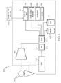
- FIG. 1 is a functional block diagram of a flight display system
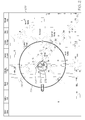
- FIG. 2 is a first image displayed in accordance with a first exemplary embodiment that may be rendered on the flight display system of FIG. 1 ;
- FIG. 3 is a second image displayed in accordance with a second exemplary embodiment that may be rendered on the flight display system of FIG. 1 ;
- FIG. 4 is a third image displayed in accordance with a third exemplary embodiment that may be rendered on the flight display system of FIG. 1 ;
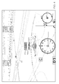
- FIG. 5 is a fourth image displayed in accordance with a fourth exemplary embodiment that may be rendered on the flight display system of FIG. 1 ;
- FIG. 6 is a flow chart of the steps of the first through fourth exemplary embodiments.
- FIG. 7 is a flow chart of the steps of a fifth exemplary embodiment.
- a method for presenting taxi markers which may also be referred to as landmarks, in different or changing formats, for example, blinking and highlighting, to alert the pilot that he is near or approaching an important landmark.
- Information pertinent for a safe taxing procedure is displayed to the pilot.
- Pertinent information may relate to a taxi turn point, a hold line for entering a runway (number one for take off, or for crossing an active runway), an obstacle (airport construction), and designated non-taxi areas.
- a display system presents images on a screen, viewable by an aircrew member, of taxiways, runways, and obstacles presented to taxing.
- the format of these taxiways, runways, and obstacles may change based on importance to the pilot before or during taxi.
- the format may blossom as the aircraft approaches a specific taxiway, runway, or obstacle.
- the word "blossom" as used herein means to change format.
- the format may include, for example, difference in size, color, or brightness, and may temporally vary in brightness, for example, blinking, flashing, or fading.
- the images presented within the aircraft may be responsive to information received from ground control. For example, clearance to cross a hold line is transmitted from ground control from data link 120 to the aircraft's data link unit 116.
- This clearance is processed by the processor 104, and along with the aircrafts approach to the hold line, prompts the blossoming of the hold line.
- the images presented within the aircraft may be responsive to information received from another aircraft. For example, a landmark may blossom more prominently as the aircraft approaches a runway and a transponder signal is received from an aircraft indicating that it is moving on the runway.
- the system 100 includes a user interface 102, a processor 104, one or more terrain/taxiway databases 106, one or more navigation databases 108, various optional sensors 112 (for the cockpit display version), various external data sources 114, and a display device 116.
- the user interface 102 and the display device 116 may be combined in the same device, for example, a touch pad.
- the user interface 102 is in operable communication with the processor 104 and is configured to receive input from a user 109 (e.g., a pilot) and, in response to the user input, supply command signals to the processor 104.
- a user 109 e.g., a pilot
- the user interface 102 may be any one, or combination, of various known user interface devices including, but not limited to, a cursor control device (CCD) 107, such as a mouse, a trackball, or joystick, and/or a keyboard, one or more buttons, switches, or knobs.
- a cursor control device CCD
- a keyboard such as a mouse, a trackball, or joystick
- buttons, switches, or knobs such as a keyboard, one or more buttons, switches, or knobs.
- the processor 104 may be any one of numerous known general-purpose microprocessors or an application specific processor that operates in response to program instructions.
- the processor 104 includes on-board RAM (random access memory) 103, and on-board ROM (read only memory) 105.
- the program instructions that control the processor 104 may be stored in either or both the RAM 103 and the ROM 105.
- the operating system software may be stored in the ROM 105, whereas various operating mode software routines and various operational parameters may be stored in the RAM 103. It will be appreciated that this is merely exemplary of one scheme for storing operating system software and software routines, and that various other storage schemes may be implemented.
- the processor 104 may be implemented using various other circuits, not just a programmable processor. For example, digital logic circuits and analog signal processing circuits could also be used.
- the processor 104 is in operable communication with the terrain/taxiway databases 106, the navigation databases 108, and the display device 116, and is coupled to receive various types of inertial data from the various sensors 112, and various other avionics-related data from the external data sources 114.
- the processor 104 is configured, in response to the inertial data and the avionics-related data, to selectively retrieve terrain data from one or more of the terrain/taxiway databases 106 and navigation data from one or more of the navigation databases 108, and to supply appropriate display commands to the display device 116.
- the display device 116 in response to the display commands from, for example, a touch screen, keypad, cursor control, line select, concentric knobs, voice control, and datalink message, selectively renders various types of textual, graphic, and/or iconic information.
- the preferred manner in which the textual, graphic, and/or iconic information are rendered by the display device 116 will be described in more detail further below. Before doing so, however, a brief description of the databases 106, 108, the sensors 112, and the external data sources 114, at least in the depicted embodiment, will be provided.
- the terrain/taxiway databases 106 include various types of data representative of the surface over which the aircraft is taxing, the terrain over which the aircraft is flying, and the navigation databases 108 include various types of navigation-related data.
- These navigation-related data include various flight plan related data such as, for example, waypoints, distances between waypoints, headings between waypoints, data related to different airports, navigational aids, obstructions, special use airspace, political boundaries, communication frequencies, and aircraft approach information.
- terrain/taxiway databases 106 and the navigation databases 108 are, for clarity and convenience, shown as being stored separate from the processor 104, all or portions of either or both of these databases 106, 108 could be loaded into the RAM 103, or integrally formed as part of the processor 104, and/or RAM 103, and/or ROM 105.
- the terrain/taxiway databases 106 and navigation databases 108 could also be part of a device or system that is physically separate from the system 100.
- the sensors 112 may be implemented using various types of inertial sensors, systems, and or subsystems, now known or developed in the future, for supplying various types of inertial data.
- the inertial data may also vary, but preferably include data representative of the state of the aircraft such as, for example, aircraft speed, heading, altitude, and attitude.
- the number and type of external data sources 114 may also vary.
- the external systems (or subsystems) may include, for example, a terrain avoidance and warning system (TAWS), a traffic and collision avoidance system (TCAS), a runway awareness and advisory system (RAAS), a flight director, and a navigation computer, just to name a few.
- TAWS terrain avoidance and warning system
- TCAS traffic and collision avoidance system
- RAAS runway awareness and advisory system
- flight director and a navigation computer
- the GPS receiver 122 is a multi-channel receiver, with each channel tuned to receive one or more of the GPS broadcast signals transmitted by the constellation of GPS satellites (not illustrated) orbiting the earth. Each GPS satellite encircles the earth two times each day, and the orbits are arranged so that at least four satellites are always within line of sight from almost anywhere on the earth.
- the GPS receiver 122 upon receipt of the GPS broadcast signals from at least three, and preferably four, or more of the GPS satellites, determines the distance between the GPS receiver 122 and the GPS satellites and the position of the GPS satellites. Based on these determinations, the GPS receiver 122, using a technique known as trilateration, determines, for example, aircraft position, groundspeed, and ground track angle. These data may be supplied to the processor 104, which may determine aircraft glide slope deviation therefrom. Preferably, however, the GPS receiver 122 is configured to determine, and supply data representative of, aircraft glide slope deviation to the processor 104.
- the display device 116 in response to display commands supplied from the processor 104, selectively renders various textual, graphic, and/or iconic information, and thereby supply visual feedback to the user 109.
- the display device 116 may be implemented using any one of numerous known display devices suitable for rendering textual, graphic, and/or iconic information in a format viewable by the user 109.
- Non-limiting examples of such display devices include various cathode ray tube (CRT) displays, and various flat panel displays such as various types of LCD (liquid crystal display) and TFT (thin film transistor) displays.
- the display device 116 may additionally be implemented as a panel mounted display, a HUD (head-up display) projection, or any one of numerous known technologies.
- the display device 116 may be configured as any one of numerous types of aircraft flight deck displays. For example, it may be configured as a multi-function display, a horizontal situation indicator, or a vertical situation indicator, just to name a few. In the depicted embodiment, however, the display device 116 is configured as a primary flight display (PFD).
- PFD primary flight display
- the display 116 includes a display area 200 in which multiple graphical images may be simultaneously displayed.
- Data for the location and boundaries of the taxiways A, B, C, D, E, G, K (and various numbered branches thereof), and runway 210 (runway 11-29) are stored in the terrain/taxiway database 106 and are processed by the processor 104 for display.
- Positional data (location, direction, speed) is determined, by data received by the GPS system 122 and processed for the base aircraft 202 which contains the flight deck display system 100.
- Images of the taxiways A, B, C, D, E, G, K, runway 210, and aircraft 202 are displayed on the display area 200 in a location determined by the positional data.
- the display area 200 may also include obstacles (not shown), such as airport construction, lighting, and non-taxi areas.
- the circle 204 indicates a distance from the aircraft 202, and in this example, is 0.2 tenths of a mile.
- a hold line 208 Marked on the surface of the intersection 206 between taxiways A4 and A5 is a hold line 208. Airplanes are not permitted to cross the hold line 208 onto runway 11-29 until given clearance by ground control. Typically the edge, or boundary, 210 of the runway 11-29 is marked. These markings are typically painted on the taxiway and runway surface.
- the hold line 208 blossoms to alert the aircrew of its location ( FIG. 3 ).
- the runway boundary 210 may also blossom.
- the word "blossom" means to change format. This format change, for example, means that the hold line 208 may increase in brightness or size, blink, change color, or be displayed in three dimensions.
- the aircraft 202 taxies out to the runway 210, it may encounter obstacles, for example, construction and structures. The obstacles, or an area of the taxiway or an area adjacent to the taxiway in which an obstacle exists, may also blossom as the aircraft approaches.
- a hold line may also be more than just a line on the taxiway.
- the hold "line” is shown on the taxiway 302 as a diagram 304 on the screen 300, including for example, lines 306 and squares 308.
- a banner 314 representative of the diagram 304 appears in a three dimensional view above the taxiway 302.
- a textual message 316 for example, the word HOLD may appear on the banner 314.
- the pilot may adjust a threshold that determines when the blossoming occurs. For example, the pilot may adjust the distance of the aircraft to the landmark that initiates the blossoming. In fog, the pilot may desire to have the blossoming occur at 800 feet instead of, say for example, 400 feet. Alternatively, the pilot may desire to adjust the threshold for a particular type of hazard, for example, a turn point.
- a banner 402 is provided in a fourth exemplary embodiment as the aircraft 404 is departing the runway 406 onto taxiway 408.
- the banner 402 may contain symbols (not shown), or a textual message such as DEPART RUNWAY 34L. This would inform the pilot that the taxi marked with the textual message is the ground control desired taxiway in which to depart the runway.
- FIG. 6 is a flow chart of the steps in the first. second, third, and fourth exemplary embodiments, the exemplary method for enhancing ground situational awareness of an aircrew via a display within an aircraft operating at an airport, including displaying 602 at least one taxiway for the airport and optionally at least one runway, displaying 604 a landmark related to the at least one taxiway, determining 606 the position of the aircraft, displaying 608 the aircraft, and blossoming 610 the landmark as the aircraft approaches the landmark.
- FIG. 7 is a flow chart of the steps in a fifth exemplary embodiment in which instructions are received 702 from ground control, at least one taxiway and runway are displayed 704, a landmark related to the runway is displayed 706, the position of the aircraft is determined 708, the aircraft is displayed 710, and the landmark is blossomed 712 in response to the instructions from ground control and the aircraft approaching the landmark.
Landscapes
- Engineering & Computer Science (AREA)
- Aviation & Aerospace Engineering (AREA)
- Physics & Mathematics (AREA)
- General Physics & Mathematics (AREA)
- Radar, Positioning & Navigation (AREA)
- Remote Sensing (AREA)
- Traffic Control Systems (AREA)
Abstract
Description
- The present invention generally relates to ground operation of aircraft and more particularly to a method and system for surface movement situation awareness for aircraft on runways and taxiways.
- It is important for pilots to know the layout of the taxiways and runways when taxing for takeoff or from landing. Navigation of an airport surface (taxiways/runways) can be as difficult (from a pilot's workload perspective) and dangerous (from an aviation safety perspective) as the airborne portion of the flight, especially in limited visibility of night and/or weather, or at unfamiliar airports. An increase in pilot workload typically results in decreased safety: the pilot must interpret the information provided on the screen occupying her thought processes when she may have many other decisions to make. Undesired results include taxing onto unapproved taxiways/runways and becoming disorientated while taxing.
- Traditionally, pilots have relied upon paper charts to gain knowledge of the airport layout and understand their position within, and how to navigate, the airport taxiway/runway matrix. More recently, this information has been made available to the pilot by electronic flight bags and electronic chart readers. However, these known electronic displays are typically monochromatic and without any prominence provided for runways and critical markers, making it difficult for the pilot to properly discern between taxiways, runways, and obstacles such as construction and slopes in the taxiway.
- Accordingly, it is desirable to provide a method and system displaying emphasized markers/landmarks in a airport taxi environment that may be more easily understood by the pilot. Furthermore, other desirable features and characteristics of the present invention will become apparent from the subsequent detailed description and the appended claims, taken in conjunction with the accompanying drawings and the foregoing technical field and background.
- A method is described for enhancing ground situational awareness to an aircrew via a display within an aircraft operating at an airport, including displaying at least one taxiway for the airport, displaying at least one runway for the airport, displaying a landmark related to the at least one taxiway, determining the position of the aircraft, displaying the aircraft, and blossoming the landmark as the aircraft approaches the landmark.
- A ground situational awareness system for an aircraft is described, including a display, a system for determining the position of the aircraft in relation to a plurality of taxiways and a landmark, and a processor, wherein the processor is configured to display the plurality of taxiways, display the aircraft, display the landmark, and blossom the landmark as the aircraft approaches the landmark.
- The present invention will hereinafter be described in conjunction with the following drawing figures, wherein like numerals denote like elements, and
-
FIG. 1 is a functional block diagram of a flight display system; -
FIG. 2 is a first image displayed in accordance with a first exemplary embodiment that may be rendered on the flight display system ofFIG. 1 ; -
FIG. 3 is a second image displayed in accordance with a second exemplary embodiment that may be rendered on the flight display system ofFIG. 1 ; -
FIG. 4 is a third image displayed in accordance with a third exemplary embodiment that may be rendered on the flight display system ofFIG. 1 ; -
FIG. 5 is a fourth image displayed in accordance with a fourth exemplary embodiment that may be rendered on the flight display system ofFIG. 1 ; and -
FIG. 6 is a flow chart of the steps of the first through fourth exemplary embodiments; and -
FIG. 7 is a flow chart of the steps of a fifth exemplary embodiment. - The following detailed description of the invention is merely exemplary in nature and is not intended to limit the invention or the application and uses of the invention. Furthermore, there is no intention to be bound by any theory presented in the preceding technical field, background, brief summary, or the following detailed description.
- A method is disclosed for presenting taxi markers, which may also be referred to as landmarks, in different or changing formats, for example, blinking and highlighting, to alert the pilot that he is near or approaching an important landmark. Information pertinent for a safe taxing procedure is displayed to the pilot. Pertinent information, for example, may relate to a taxi turn point, a hold line for entering a runway (number one for take off, or for crossing an active runway), an obstacle (airport construction), and designated non-taxi areas.
- A display system presents images on a screen, viewable by an aircrew member, of taxiways, runways, and obstacles presented to taxing. The format of these taxiways, runways, and obstacles may change based on importance to the pilot before or during taxi. The format may blossom as the aircraft approaches a specific taxiway, runway, or obstacle. The word "blossom" as used herein means to change format. The format may include, for example, difference in size, color, or brightness, and may temporally vary in brightness, for example, blinking, flashing, or fading. In one embodiment, the images presented within the aircraft may be responsive to information received from ground control. For example, clearance to cross a hold line is transmitted from ground control from
data link 120 to the aircraft'sdata link unit 116. This clearance is processed by theprocessor 104, and along with the aircrafts approach to the hold line, prompts the blossoming of the hold line. In yet another embodiment, the images presented within the aircraft may be responsive to information received from another aircraft. For example, a landmark may blossom more prominently as the aircraft approaches a runway and a transponder signal is received from an aircraft indicating that it is moving on the runway. - While the exemplary embodiments described herein refer to displaying the information on ground based aircraft, the invention may also be applied to other exemplary embodiments such as displays in sea going vessels and displays used by traffic controllers.
- Referring to
FIG. 1 , an exemplary flightdeck display system 100 is depicted and will be described for displaying winds aloft at various altitudes. Thesystem 100 includes auser interface 102, aprocessor 104, one or more terrain/taxiway databases 106, one or more navigation databases 108, various optional sensors 112 (for the cockpit display version), variousexternal data sources 114, and adisplay device 116. In some embodiments theuser interface 102 and thedisplay device 116 may be combined in the same device, for example, a touch pad. Theuser interface 102 is in operable communication with theprocessor 104 and is configured to receive input from a user 109 (e.g., a pilot) and, in response to the user input, supply command signals to theprocessor 104. Theuser interface 102 may be any one, or combination, of various known user interface devices including, but not limited to, a cursor control device (CCD) 107, such as a mouse, a trackball, or joystick, and/or a keyboard, one or more buttons, switches, or knobs. - The
processor 104 may be any one of numerous known general-purpose microprocessors or an application specific processor that operates in response to program instructions. In the depicted embodiment, theprocessor 104 includes on-board RAM (random access memory) 103, and on-board ROM (read only memory) 105. The program instructions that control theprocessor 104 may be stored in either or both theRAM 103 and theROM 105. For example, the operating system software may be stored in theROM 105, whereas various operating mode software routines and various operational parameters may be stored in theRAM 103. It will be appreciated that this is merely exemplary of one scheme for storing operating system software and software routines, and that various other storage schemes may be implemented. It will also be appreciated that theprocessor 104 may be implemented using various other circuits, not just a programmable processor. For example, digital logic circuits and analog signal processing circuits could also be used. - No matter how the
processor 104 is specifically implemented, it is in operable communication with the terrain/taxiway databases 106, the navigation databases 108, and thedisplay device 116, and is coupled to receive various types of inertial data from thevarious sensors 112, and various other avionics-related data from theexternal data sources 114. Theprocessor 104 is configured, in response to the inertial data and the avionics-related data, to selectively retrieve terrain data from one or more of the terrain/taxiway databases 106 and navigation data from one or more of the navigation databases 108, and to supply appropriate display commands to thedisplay device 116. Thedisplay device 116, in response to the display commands from, for example, a touch screen, keypad, cursor control, line select, concentric knobs, voice control, and datalink message, selectively renders various types of textual, graphic, and/or iconic information. The preferred manner in which the textual, graphic, and/or iconic information are rendered by thedisplay device 116 will be described in more detail further below. Before doing so, however, a brief description of thedatabases 106, 108, thesensors 112, and theexternal data sources 114, at least in the depicted embodiment, will be provided. - The terrain/
taxiway databases 106 include various types of data representative of the surface over which the aircraft is taxing, the terrain over which the aircraft is flying, and the navigation databases 108 include various types of navigation-related data. These navigation-related data include various flight plan related data such as, for example, waypoints, distances between waypoints, headings between waypoints, data related to different airports, navigational aids, obstructions, special use airspace, political boundaries, communication frequencies, and aircraft approach information. It will be appreciated that, although the terrain/taxiway databases 106 and the navigation databases 108 are, for clarity and convenience, shown as being stored separate from theprocessor 104, all or portions of either or both of thesedatabases 106, 108 could be loaded into theRAM 103, or integrally formed as part of theprocessor 104, and/orRAM 103, and/orROM 105. The terrain/taxiway databases 106 and navigation databases 108 could also be part of a device or system that is physically separate from thesystem 100. - The
sensors 112 may be implemented using various types of inertial sensors, systems, and or subsystems, now known or developed in the future, for supplying various types of inertial data. The inertial data may also vary, but preferably include data representative of the state of the aircraft such as, for example, aircraft speed, heading, altitude, and attitude. The number and type ofexternal data sources 114 may also vary. For example, the external systems (or subsystems) may include, for example, a terrain avoidance and warning system (TAWS), a traffic and collision avoidance system (TCAS), a runway awareness and advisory system (RAAS), a flight director, and a navigation computer, just to name a few. However, for ease of description and illustration, only adatalink unit 116 and a global position system (GPS)receiver 122 are depicted inFIG. 1 , and will now be briefly described. - The
GPS receiver 122 is a multi-channel receiver, with each channel tuned to receive one or more of the GPS broadcast signals transmitted by the constellation of GPS satellites (not illustrated) orbiting the earth. Each GPS satellite encircles the earth two times each day, and the orbits are arranged so that at least four satellites are always within line of sight from almost anywhere on the earth. TheGPS receiver 122, upon receipt of the GPS broadcast signals from at least three, and preferably four, or more of the GPS satellites, determines the distance between theGPS receiver 122 and the GPS satellites and the position of the GPS satellites. Based on these determinations, theGPS receiver 122, using a technique known as trilateration, determines, for example, aircraft position, groundspeed, and ground track angle. These data may be supplied to theprocessor 104, which may determine aircraft glide slope deviation therefrom. Preferably, however, theGPS receiver 122 is configured to determine, and supply data representative of, aircraft glide slope deviation to theprocessor 104. - The
display device 116, as noted above, in response to display commands supplied from theprocessor 104, selectively renders various textual, graphic, and/or iconic information, and thereby supply visual feedback to theuser 109. It will be appreciated that thedisplay device 116 may be implemented using any one of numerous known display devices suitable for rendering textual, graphic, and/or iconic information in a format viewable by theuser 109. Non-limiting examples of such display devices include various cathode ray tube (CRT) displays, and various flat panel displays such as various types of LCD (liquid crystal display) and TFT (thin film transistor) displays. Thedisplay device 116 may additionally be implemented as a panel mounted display, a HUD (head-up display) projection, or any one of numerous known technologies. It is additionally noted that thedisplay device 116 may be configured as any one of numerous types of aircraft flight deck displays. For example, it may be configured as a multi-function display, a horizontal situation indicator, or a vertical situation indicator, just to name a few. In the depicted embodiment, however, thedisplay device 116 is configured as a primary flight display (PFD). - With reference to
FIG. 2 , thedisplay 116 includes adisplay area 200 in which multiple graphical images may be simultaneously displayed. Data for the location and boundaries of the taxiways A, B, C, D, E, G, K (and various numbered branches thereof), and runway 210 (runway 11-29) are stored in the terrain/taxiway database 106 and are processed by theprocessor 104 for display. Positional data (location, direction, speed) is determined, by data received by theGPS system 122 and processed for thebase aircraft 202 which contains the flightdeck display system 100. Images of the taxiways A, B, C, D, E, G, K,runway 210, andaircraft 202 are displayed on thedisplay area 200 in a location determined by the positional data. Thedisplay area 200 may also include obstacles (not shown), such as airport construction, lighting, and non-taxi areas. Thecircle 204 indicates a distance from theaircraft 202, and in this example, is 0.2 tenths of a mile. - Marked on the surface of the
intersection 206 between taxiways A4 and A5 is ahold line 208. Airplanes are not permitted to cross thehold line 208 onto runway 11-29 until given clearance by ground control. Typically the edge, or boundary, 210 of the runway 11-29 is marked. These markings are typically painted on the taxiway and runway surface. - In accordance with a first exemplary embodiment, as the
aircraft 202 approaches thehold line 208, thehold line 208 blossoms to alert the aircrew of its location (FIG. 3 ). Optionally, therunway boundary 210 may also blossom. The word "blossom" means to change format. This format change, for example, means that thehold line 208 may increase in brightness or size, blink, change color, or be displayed in three dimensions. Additionally, as theaircraft 202 taxies out to therunway 210, it may encounter obstacles, for example, construction and structures. The obstacles, or an area of the taxiway or an area adjacent to the taxiway in which an obstacle exists, may also blossom as the aircraft approaches. - A hold line may also be more than just a line on the taxiway. Referring to
FIG. 3 , the hold "line" is shown on thetaxiway 302 as a diagram 304 on the screen 300, including for example,lines 306 andsquares 308. In accordance with a second exemplary embodiment, as theaircraft 310 approaches therunway 312 ontaxiway 302, abanner 314 representative of the diagram 304 appears in a three dimensional view above thetaxiway 302. Optionally, in a third exemplary embodiment as shown inFIG. 4 , atextual message 316, for example, the word HOLD may appear on thebanner 314. - In each of the above described exemplary embodiments, the pilot may adjust a threshold that determines when the blossoming occurs. For example, the pilot may adjust the distance of the aircraft to the landmark that initiates the blossoming. In fog, the pilot may desire to have the blossoming occur at 800 feet instead of, say for example, 400 feet. Alternatively, the pilot may desire to adjust the threshold for a particular type of hazard, for example, a turn point.
- Referring to
FIG. 5 , abanner 402 is provided in a fourth exemplary embodiment as theaircraft 404 is departing therunway 406 ontotaxiway 408. Thebanner 402 may contain symbols (not shown), or a textual message such asDEPART RUNWAY 34L. This would inform the pilot that the taxi marked with the textual message is the ground control desired taxiway in which to depart the runway. -
FIG. 6 is a flow chart of the steps in the first. second, third, and fourth exemplary embodiments, the exemplary method for enhancing ground situational awareness of an aircrew via a display within an aircraft operating at an airport, including displaying 602 at least one taxiway for the airport and optionally at least one runway, displaying 604 a landmark related to the at least one taxiway, determining 606 the position of the aircraft, displaying 608 the aircraft, and blossoming 610 the landmark as the aircraft approaches the landmark. -
FIG. 7 is a flow chart of the steps in a fifth exemplary embodiment in which instructions are received 702 from ground control, at least one taxiway and runway are displayed 704, a landmark related to the runway is displayed 706, the position of the aircraft is determined 708, the aircraft is displayed 710, and the landmark is blossomed 712 in response to the instructions from ground control and the aircraft approaching the landmark. - While at least one exemplary embodiment has been presented in the foregoing detailed description, it should be appreciated that a vast number of variations exist. It should also be appreciated that the exemplary embodiment or exemplary embodiments are only examples, and are not intended to limit the scope, applicability, or configuration of the invention in any way. Rather, the foregoing detailed description will provide those skilled in the art with a convenient road map for implementing an exemplary embodiment of the invention, it being understood that various changes may be made in the function and arrangement of elements described in an exemplary embodiment without departing from the scope of the invention as set forth in the appended claims.
Claims (10)
- A method for enhancing ground situational awareness of an aircrew via a display within an aircraft operating at an airport having a runway, comprising:displaying at least one taxiway for the airport;displaying a first landmark related to the at least one taxiway;determining the position of the aircraft;displaying the aircraft; andblossoming the first landmark as the aircraft approaches the first landmark.
- The method of claim 1 further comprising:displaying the runway;displaying a second landmark related to the runway; andblossoming the second landmark as the aircraft approaches the second landmark.
- The method of claim 1 wherein the blossoming step comprises changing the color of the first landmark.
- The method of claim 1 wherein the blossoming step comprises increasing the intensity of the first landmark.
- The method of claim 1 wherein the blossoming step comprises changing the dimensions of the first landmark.
- The method of claim 1 wherein the blossoming step comprises displaying the first landmark in three dimensions.
- The method of claim 6 wherein the blossoming step comprises displaying text on the first landmark.
- The method of claim 1 further comprising receiving information from ground control wherein the blossoming step occurs in response thereto.
- The method of claim 1 further comprising receiving information from another aircraft wherein the blossoming step occurs in response thereto.
- The method of claim 1 further comprising adjusting a threshold at which the blossoming occurs.
Applications Claiming Priority (1)
| Application Number | Priority Date | Filing Date | Title |
|---|---|---|---|
| US12/627,760 US8903655B2 (en) | 2009-11-30 | 2009-11-30 | Method and system for displaying emphasized aircraft taxi landmarks |
Publications (3)
| Publication Number | Publication Date |
|---|---|
| EP2327962A2 true EP2327962A2 (en) | 2011-06-01 |
| EP2327962A3 EP2327962A3 (en) | 2015-05-06 |
| EP2327962B1 EP2327962B1 (en) | 2020-12-09 |
Family
ID=43567927
Family Applications (1)
| Application Number | Title | Priority Date | Filing Date |
|---|---|---|---|
| EP10189493.9A Active EP2327962B1 (en) | 2009-11-30 | 2010-10-29 | Method and system for displaying emphasized aircraft taxi landmarks |
Country Status (2)
| Country | Link |
|---|---|
| US (1) | US8903655B2 (en) |
| EP (1) | EP2327962B1 (en) |
Cited By (6)
| Publication number | Priority date | Publication date | Assignee | Title |
|---|---|---|---|---|
| EP2624237A1 (en) * | 2012-02-06 | 2013-08-07 | Honeywell International Inc. | Display of an aircraft taxi clearance |
| FR2989205A1 (en) * | 2012-04-06 | 2013-10-11 | Thales Sa | Guide system for guiding aircraft operating on airport area, has calculation unit determining driving indications of aircraft, and display unit displaying view of airport area in which aircraft is situated and representation of indications |
| EP2709084A3 (en) * | 2012-09-14 | 2014-06-18 | Honeywell International Inc. | Systems and methods for providing runway-entry awareness and alerting |
| CN107077150A (en) * | 2016-11-14 | 2017-08-18 | 深圳市大疆创新科技有限公司 | Control method, control device and electronic installation |
| US10672279B2 (en) | 2017-09-26 | 2020-06-02 | Honeywell International Inc. | Systems and methods for presenting an intuitive timeline visualization via an avionics primary flight display (PFD) |
| EP3819894A1 (en) * | 2019-11-05 | 2021-05-12 | Rockwell Collins, Inc. | Graphical depiction of an exclusion zone on an airport movement surface |
Families Citing this family (13)
| Publication number | Priority date | Publication date | Assignee | Title |
|---|---|---|---|---|
| US9734729B2 (en) * | 2013-04-11 | 2017-08-15 | Honeywell International Inc. | Methods and systems for providing taxiway stop bar information to an aircrew |
| US9355567B2 (en) * | 2013-08-08 | 2016-05-31 | Honeywell International Inc. | System and method for highlighting an area encompassing an aircraft that is free of hazards |
| US9487304B1 (en) * | 2013-09-10 | 2016-11-08 | Rockwell Collins, Inc. | Advisory generating system, device, and method |
| US9396663B2 (en) * | 2014-07-14 | 2016-07-19 | The Boeing Company | Systems and methods of airport traffic control |
| US9620119B2 (en) * | 2014-09-26 | 2017-04-11 | Honeywell International Inc. | Systems and methods for converting taxiway voice commands into taxiway textual commands |
| FR3045176B1 (en) * | 2015-12-15 | 2019-10-11 | Airbus Helicopters | DEVICE AND METHOD FOR ASSISTING THE CONTROL OF AN AIRCRAFT |
| EP3261081A1 (en) | 2016-06-22 | 2017-12-27 | GE Aviation Systems Limited | Natural travel mode description system |
| US10748430B2 (en) | 2018-07-23 | 2020-08-18 | Honeywell International Inc. | Systems and methods for selective terrain deemphasis |
| CN110400061B (en) * | 2019-07-05 | 2020-10-02 | 中国民航科学技术研究院 | A method, device, controller and storage medium for comprehensive assessment of flight safety |
| US11335009B2 (en) * | 2020-04-27 | 2022-05-17 | University Of Malta | Method and system for aerodrome taxiway surface marking detection |
| US11610497B2 (en) * | 2020-12-15 | 2023-03-21 | Rockwell Collins, Inc. | System and method to display SVS taxi mode exocentric view of aircraft |
| US11941995B2 (en) * | 2021-09-01 | 2024-03-26 | Honeywell International Inc. | Runway awareness and alerting systems and methods |
| US20250292694A1 (en) * | 2024-01-16 | 2025-09-18 | Honeywell International Inc. | Systems and methods for aircraft ground collision avoidance |
Family Cites Families (13)
| Publication number | Priority date | Publication date | Assignee | Title |
|---|---|---|---|---|
| US6571166B1 (en) * | 2000-06-23 | 2003-05-27 | Rockwell Collins, Inc. | Airport surface operation advisory system |
| US6789010B2 (en) * | 2001-12-04 | 2004-09-07 | Smiths Aerospace, Inc. | Airport map display system and data interchange method |
| US6731226B2 (en) * | 2001-12-04 | 2004-05-04 | Smiths Aerospace, Inc. | Airport feature display system and data interchange method for conformal display |
| US7564372B1 (en) * | 2004-06-30 | 2009-07-21 | Rockwell Collins, Inc. | Display of hold lines on head-up display |
| US7382288B1 (en) * | 2004-06-30 | 2008-06-03 | Rockwell Collins, Inc. | Display of airport signs on head-up display |
| FR2891646B1 (en) * | 2005-09-30 | 2016-07-01 | Thales Sa | METHOD AND APPARATUS FOR ROLLING AID IN AN AIRPORT. |
| US7908078B2 (en) * | 2005-10-13 | 2011-03-15 | Honeywell International Inc. | Perspective-view visual runway awareness and advisory display |
| US7737867B2 (en) * | 2006-04-13 | 2010-06-15 | The United States Of America As Represented By The United States National Aeronautics And Space Administration | Multi-modal cockpit interface for improved airport surface operations |
| US7963618B2 (en) * | 2006-06-12 | 2011-06-21 | Aviation Communication & Surveillance Systems Llc | Systems and methods for providing aircraft runway guidance |
| US7908082B2 (en) * | 2007-05-04 | 2011-03-15 | The Boeing Company | Methods and systems for displaying airport moving map information |
| US7962279B2 (en) * | 2007-05-29 | 2011-06-14 | Honeywell International Inc. | Methods and systems for alerting an aircraft crew member of a potential conflict between aircraft on a taxiway |
| FR2917223B1 (en) * | 2007-06-08 | 2009-07-17 | Thales Sa | AIDING SYSTEM FOR GUIDING AN AIRCRAFT ON AN AIRPORT |
| US8401775B2 (en) * | 2009-01-30 | 2013-03-19 | The Boeing Company | Systems and method for managing airport ground traffic |
-
2009
- 2009-11-30 US US12/627,760 patent/US8903655B2/en active Active
-
2010
- 2010-10-29 EP EP10189493.9A patent/EP2327962B1/en active Active
Non-Patent Citations (1)
| Title |
|---|
| None |
Cited By (9)
| Publication number | Priority date | Publication date | Assignee | Title |
|---|---|---|---|---|
| EP2624237A1 (en) * | 2012-02-06 | 2013-08-07 | Honeywell International Inc. | Display of an aircraft taxi clearance |
| FR2989205A1 (en) * | 2012-04-06 | 2013-10-11 | Thales Sa | Guide system for guiding aircraft operating on airport area, has calculation unit determining driving indications of aircraft, and display unit displaying view of airport area in which aircraft is situated and representation of indications |
| US9047769B2 (en) | 2012-04-06 | 2015-06-02 | Thales | System for aiding the guidance of an aircraft travelling around an airport zone |
| EP2709084A3 (en) * | 2012-09-14 | 2014-06-18 | Honeywell International Inc. | Systems and methods for providing runway-entry awareness and alerting |
| US9092976B2 (en) | 2012-09-14 | 2015-07-28 | Honeywell International Inc. | Systems and methods for providing runway-entry awareness and alerting |
| CN107077150A (en) * | 2016-11-14 | 2017-08-18 | 深圳市大疆创新科技有限公司 | Control method, control device and electronic installation |
| CN107077150B (en) * | 2016-11-14 | 2018-12-18 | 深圳市大疆创新科技有限公司 | Control method, control device and electronic device |
| US10672279B2 (en) | 2017-09-26 | 2020-06-02 | Honeywell International Inc. | Systems and methods for presenting an intuitive timeline visualization via an avionics primary flight display (PFD) |
| EP3819894A1 (en) * | 2019-11-05 | 2021-05-12 | Rockwell Collins, Inc. | Graphical depiction of an exclusion zone on an airport movement surface |
Also Published As
| Publication number | Publication date |
|---|---|
| US20110130963A1 (en) | 2011-06-02 |
| US8903655B2 (en) | 2014-12-02 |
| EP2327962A3 (en) | 2015-05-06 |
| EP2327962B1 (en) | 2020-12-09 |
Similar Documents
| Publication | Publication Date | Title |
|---|---|---|
| US8903655B2 (en) | Method and system for displaying emphasized aircraft taxi landmarks | |
| US8736633B2 (en) | Traffic symbology on airport moving map | |
| US7603209B2 (en) | Perspective vertical situation display system and method | |
| EP1835369B1 (en) | Ground incursion avoidance system and display | |
| EP1852683B1 (en) | System and method for distributively displaying terminal procedure data | |
| EP1896797B1 (en) | Perspective view primary flight display with terrain-tracing lines | |
| US8160755B2 (en) | Displaying air traffic symbology based on relative importance | |
| EP2299422A1 (en) | Method and system displaying aircraft in-trail traffic | |
| EP1797397B1 (en) | System and method for enhanced situational awareness of terrain in a vertical situation display | |
| EP2166311B1 (en) | Apparatus and method for setting a waypoint | |
| EP2180457A1 (en) | Method and apparatus for displaying prioritized photo realistic features on a synthetic vision system | |
| US20100070176A1 (en) | Perspective view primary flight display system and method with range lines | |
| EP1944580A1 (en) | Aircraft glide slope display system and method | |
| EP2200004A1 (en) | System for selectively displaying terminal procedure data | |
| US7477985B2 (en) | Method and apparatus for displaying TCAS information with enhanced vertical situational awareness | |
| EP2624237A1 (en) | Display of an aircraft taxi clearance | |
| US20060241820A1 (en) | System and method for displaying the protected airspace associated with a circle-to-land maneuver | |
| EP1764759A1 (en) | System and method for displaying protected or restricted airspace inside an aircraft | |
| EP2565668A1 (en) | Method and apparatus for providing motion cues in compressed displays |
Legal Events
| Date | Code | Title | Description |
|---|---|---|---|
| PUAI | Public reference made under article 153(3) epc to a published international application that has entered the european phase |
Free format text: ORIGINAL CODE: 0009012 |
|
| 17P | Request for examination filed |
Effective date: 20101029 |
|
| AK | Designated contracting states |
Kind code of ref document: A2 Designated state(s): AL AT BE BG CH CY CZ DE DK EE ES FI FR GB GR HR HU IE IS IT LI LT LU LV MC MK MT NL NO PL PT RO RS SE SI SK SM TR |
|
| AX | Request for extension of the european patent |
Extension state: BA ME |
|
| PUAL | Search report despatched |
Free format text: ORIGINAL CODE: 0009013 |
|
| AK | Designated contracting states |
Kind code of ref document: A3 Designated state(s): AL AT BE BG CH CY CZ DE DK EE ES FI FR GB GR HR HU IE IS IT LI LT LU LV MC MK MT NL NO PL PT RO RS SE SI SK SM TR |
|
| AX | Request for extension of the european patent |
Extension state: BA ME |
|
| RIC1 | Information provided on ipc code assigned before grant |
Ipc: G01C 23/00 20060101AFI20150405BHEP Ipc: G08G 5/06 20060101ALI20150405BHEP |
|
| 17Q | First examination report despatched |
Effective date: 20150521 |
|
| RAP1 | Party data changed (applicant data changed or rights of an application transferred) |
Owner name: HONEYWELL INTERNATIONAL INC. |
|
| STAA | Information on the status of an ep patent application or granted ep patent |
Free format text: STATUS: EXAMINATION IS IN PROGRESS |
|
| GRAP | Despatch of communication of intention to grant a patent |
Free format text: ORIGINAL CODE: EPIDOSNIGR1 |
|
| STAA | Information on the status of an ep patent application or granted ep patent |
Free format text: STATUS: GRANT OF PATENT IS INTENDED |
|
| INTG | Intention to grant announced |
Effective date: 20200729 |
|
| GRAS | Grant fee paid |
Free format text: ORIGINAL CODE: EPIDOSNIGR3 |
|
| GRAA | (expected) grant |
Free format text: ORIGINAL CODE: 0009210 |
|
| STAA | Information on the status of an ep patent application or granted ep patent |
Free format text: STATUS: THE PATENT HAS BEEN GRANTED |
|
| AK | Designated contracting states |
Kind code of ref document: B1 Designated state(s): AL AT BE BG CH CY CZ DE DK EE ES FI FR GB GR HR HU IE IS IT LI LT LU LV MC MK MT NL NO PL PT RO RS SE SI SK SM TR |
|
| REG | Reference to a national code |
Ref country code: GB Ref legal event code: FG4D |
|
| REG | Reference to a national code |
Ref country code: AT Ref legal event code: REF Ref document number: 1343896 Country of ref document: AT Kind code of ref document: T Effective date: 20201215 Ref country code: CH Ref legal event code: EP |
|
| REG | Reference to a national code |
Ref country code: DE Ref legal event code: R096 Ref document number: 602010066101 Country of ref document: DE |
|
| REG | Reference to a national code |
Ref country code: IE Ref legal event code: FG4D |
|
| PG25 | Lapsed in a contracting state [announced via postgrant information from national office to epo] |
Ref country code: RS Free format text: LAPSE BECAUSE OF FAILURE TO SUBMIT A TRANSLATION OF THE DESCRIPTION OR TO PAY THE FEE WITHIN THE PRESCRIBED TIME-LIMIT Effective date: 20201209 Ref country code: FI Free format text: LAPSE BECAUSE OF FAILURE TO SUBMIT A TRANSLATION OF THE DESCRIPTION OR TO PAY THE FEE WITHIN THE PRESCRIBED TIME-LIMIT Effective date: 20201209 Ref country code: NO Free format text: LAPSE BECAUSE OF FAILURE TO SUBMIT A TRANSLATION OF THE DESCRIPTION OR TO PAY THE FEE WITHIN THE PRESCRIBED TIME-LIMIT Effective date: 20210309 Ref country code: GR Free format text: LAPSE BECAUSE OF FAILURE TO SUBMIT A TRANSLATION OF THE DESCRIPTION OR TO PAY THE FEE WITHIN THE PRESCRIBED TIME-LIMIT Effective date: 20210310 |
|
| REG | Reference to a national code |
Ref country code: AT Ref legal event code: MK05 Ref document number: 1343896 Country of ref document: AT Kind code of ref document: T Effective date: 20201209 |
|
| PG25 | Lapsed in a contracting state [announced via postgrant information from national office to epo] |
Ref country code: SE Free format text: LAPSE BECAUSE OF FAILURE TO SUBMIT A TRANSLATION OF THE DESCRIPTION OR TO PAY THE FEE WITHIN THE PRESCRIBED TIME-LIMIT Effective date: 20201209 Ref country code: LV Free format text: LAPSE BECAUSE OF FAILURE TO SUBMIT A TRANSLATION OF THE DESCRIPTION OR TO PAY THE FEE WITHIN THE PRESCRIBED TIME-LIMIT Effective date: 20201209 Ref country code: BG Free format text: LAPSE BECAUSE OF FAILURE TO SUBMIT A TRANSLATION OF THE DESCRIPTION OR TO PAY THE FEE WITHIN THE PRESCRIBED TIME-LIMIT Effective date: 20210309 |
|
| REG | Reference to a national code |
Ref country code: NL Ref legal event code: MP Effective date: 20201209 |
|
| PG25 | Lapsed in a contracting state [announced via postgrant information from national office to epo] |
Ref country code: NL Free format text: LAPSE BECAUSE OF FAILURE TO SUBMIT A TRANSLATION OF THE DESCRIPTION OR TO PAY THE FEE WITHIN THE PRESCRIBED TIME-LIMIT Effective date: 20201209 Ref country code: HR Free format text: LAPSE BECAUSE OF FAILURE TO SUBMIT A TRANSLATION OF THE DESCRIPTION OR TO PAY THE FEE WITHIN THE PRESCRIBED TIME-LIMIT Effective date: 20201209 |
|
| REG | Reference to a national code |
Ref country code: LT Ref legal event code: MG9D |
|
| PG25 | Lapsed in a contracting state [announced via postgrant information from national office to epo] |
Ref country code: SM Free format text: LAPSE BECAUSE OF FAILURE TO SUBMIT A TRANSLATION OF THE DESCRIPTION OR TO PAY THE FEE WITHIN THE PRESCRIBED TIME-LIMIT Effective date: 20201209 Ref country code: RO Free format text: LAPSE BECAUSE OF FAILURE TO SUBMIT A TRANSLATION OF THE DESCRIPTION OR TO PAY THE FEE WITHIN THE PRESCRIBED TIME-LIMIT Effective date: 20201209 Ref country code: PT Free format text: LAPSE BECAUSE OF FAILURE TO SUBMIT A TRANSLATION OF THE DESCRIPTION OR TO PAY THE FEE WITHIN THE PRESCRIBED TIME-LIMIT Effective date: 20210409 Ref country code: SK Free format text: LAPSE BECAUSE OF FAILURE TO SUBMIT A TRANSLATION OF THE DESCRIPTION OR TO PAY THE FEE WITHIN THE PRESCRIBED TIME-LIMIT Effective date: 20201209 Ref country code: CZ Free format text: LAPSE BECAUSE OF FAILURE TO SUBMIT A TRANSLATION OF THE DESCRIPTION OR TO PAY THE FEE WITHIN THE PRESCRIBED TIME-LIMIT Effective date: 20201209 Ref country code: EE Free format text: LAPSE BECAUSE OF FAILURE TO SUBMIT A TRANSLATION OF THE DESCRIPTION OR TO PAY THE FEE WITHIN THE PRESCRIBED TIME-LIMIT Effective date: 20201209 Ref country code: LT Free format text: LAPSE BECAUSE OF FAILURE TO SUBMIT A TRANSLATION OF THE DESCRIPTION OR TO PAY THE FEE WITHIN THE PRESCRIBED TIME-LIMIT Effective date: 20201209 |
|
| PG25 | Lapsed in a contracting state [announced via postgrant information from national office to epo] |
Ref country code: PL Free format text: LAPSE BECAUSE OF FAILURE TO SUBMIT A TRANSLATION OF THE DESCRIPTION OR TO PAY THE FEE WITHIN THE PRESCRIBED TIME-LIMIT Effective date: 20201209 Ref country code: AT Free format text: LAPSE BECAUSE OF FAILURE TO SUBMIT A TRANSLATION OF THE DESCRIPTION OR TO PAY THE FEE WITHIN THE PRESCRIBED TIME-LIMIT Effective date: 20201209 |
|
| REG | Reference to a national code |
Ref country code: DE Ref legal event code: R097 Ref document number: 602010066101 Country of ref document: DE |
|
| PG25 | Lapsed in a contracting state [announced via postgrant information from national office to epo] |
Ref country code: IS Free format text: LAPSE BECAUSE OF FAILURE TO SUBMIT A TRANSLATION OF THE DESCRIPTION OR TO PAY THE FEE WITHIN THE PRESCRIBED TIME-LIMIT Effective date: 20210409 |
|
| PLBE | No opposition filed within time limit |
Free format text: ORIGINAL CODE: 0009261 |
|
| STAA | Information on the status of an ep patent application or granted ep patent |
Free format text: STATUS: NO OPPOSITION FILED WITHIN TIME LIMIT |
|
| PG25 | Lapsed in a contracting state [announced via postgrant information from national office to epo] |
Ref country code: AL Free format text: LAPSE BECAUSE OF FAILURE TO SUBMIT A TRANSLATION OF THE DESCRIPTION OR TO PAY THE FEE WITHIN THE PRESCRIBED TIME-LIMIT Effective date: 20201209 Ref country code: IT Free format text: LAPSE BECAUSE OF FAILURE TO SUBMIT A TRANSLATION OF THE DESCRIPTION OR TO PAY THE FEE WITHIN THE PRESCRIBED TIME-LIMIT Effective date: 20201209 |
|
| 26N | No opposition filed |
Effective date: 20210910 |
|
| PG25 | Lapsed in a contracting state [announced via postgrant information from national office to epo] |
Ref country code: SI Free format text: LAPSE BECAUSE OF FAILURE TO SUBMIT A TRANSLATION OF THE DESCRIPTION OR TO PAY THE FEE WITHIN THE PRESCRIBED TIME-LIMIT Effective date: 20201209 Ref country code: ES Free format text: LAPSE BECAUSE OF FAILURE TO SUBMIT A TRANSLATION OF THE DESCRIPTION OR TO PAY THE FEE WITHIN THE PRESCRIBED TIME-LIMIT Effective date: 20201209 Ref country code: DK Free format text: LAPSE BECAUSE OF FAILURE TO SUBMIT A TRANSLATION OF THE DESCRIPTION OR TO PAY THE FEE WITHIN THE PRESCRIBED TIME-LIMIT Effective date: 20201209 |
|
| PG25 | Lapsed in a contracting state [announced via postgrant information from national office to epo] |
Ref country code: IS Free format text: LAPSE BECAUSE OF FAILURE TO SUBMIT A TRANSLATION OF THE DESCRIPTION OR TO PAY THE FEE WITHIN THE PRESCRIBED TIME-LIMIT Effective date: 20210409 |
|
| REG | Reference to a national code |
Ref country code: CH Ref legal event code: PL |
|
| PG25 | Lapsed in a contracting state [announced via postgrant information from national office to epo] |
Ref country code: MC Free format text: LAPSE BECAUSE OF FAILURE TO SUBMIT A TRANSLATION OF THE DESCRIPTION OR TO PAY THE FEE WITHIN THE PRESCRIBED TIME-LIMIT Effective date: 20201209 |
|
| PG25 | Lapsed in a contracting state [announced via postgrant information from national office to epo] |
Ref country code: LU Free format text: LAPSE BECAUSE OF NON-PAYMENT OF DUE FEES Effective date: 20211029 |
|
| PG25 | Lapsed in a contracting state [announced via postgrant information from national office to epo] |
Ref country code: LI Free format text: LAPSE BECAUSE OF NON-PAYMENT OF DUE FEES Effective date: 20211031 Ref country code: CH Free format text: LAPSE BECAUSE OF NON-PAYMENT OF DUE FEES Effective date: 20211031 |
|
| PG25 | Lapsed in a contracting state [announced via postgrant information from national office to epo] |
Ref country code: IE Free format text: LAPSE BECAUSE OF NON-PAYMENT OF DUE FEES Effective date: 20211029 |
|
| PG25 | Lapsed in a contracting state [announced via postgrant information from national office to epo] |
Ref country code: HU Free format text: LAPSE BECAUSE OF FAILURE TO SUBMIT A TRANSLATION OF THE DESCRIPTION OR TO PAY THE FEE WITHIN THE PRESCRIBED TIME-LIMIT; INVALID AB INITIO Effective date: 20101029 Ref country code: CY Free format text: LAPSE BECAUSE OF FAILURE TO SUBMIT A TRANSLATION OF THE DESCRIPTION OR TO PAY THE FEE WITHIN THE PRESCRIBED TIME-LIMIT Effective date: 20201209 |
|
| P01 | Opt-out of the competence of the unified patent court (upc) registered |
Effective date: 20230525 |
|
| PG25 | Lapsed in a contracting state [announced via postgrant information from national office to epo] |
Ref country code: MK Free format text: LAPSE BECAUSE OF FAILURE TO SUBMIT A TRANSLATION OF THE DESCRIPTION OR TO PAY THE FEE WITHIN THE PRESCRIBED TIME-LIMIT Effective date: 20201209 |
|
| PG25 | Lapsed in a contracting state [announced via postgrant information from national office to epo] |
Ref country code: TR Free format text: LAPSE BECAUSE OF FAILURE TO SUBMIT A TRANSLATION OF THE DESCRIPTION OR TO PAY THE FEE WITHIN THE PRESCRIBED TIME-LIMIT Effective date: 20201209 |
|
| PG25 | Lapsed in a contracting state [announced via postgrant information from national office to epo] |
Ref country code: MT Free format text: LAPSE BECAUSE OF FAILURE TO SUBMIT A TRANSLATION OF THE DESCRIPTION OR TO PAY THE FEE WITHIN THE PRESCRIBED TIME-LIMIT Effective date: 20201209 |
|
| PGFP | Annual fee paid to national office [announced via postgrant information from national office to epo] |
Ref country code: DE Payment date: 20241029 Year of fee payment: 15 |
|
| PGFP | Annual fee paid to national office [announced via postgrant information from national office to epo] |
Ref country code: BE Payment date: 20241023 Year of fee payment: 15 |
|
| PGFP | Annual fee paid to national office [announced via postgrant information from national office to epo] |
Ref country code: GB Payment date: 20241022 Year of fee payment: 15 |
|
| PGFP | Annual fee paid to national office [announced via postgrant information from national office to epo] |
Ref country code: FR Payment date: 20251027 Year of fee payment: 16 |