EP2327858A2 - Composite slider seal for turbojet penetration - Google Patents
Composite slider seal for turbojet penetration Download PDFInfo
- Publication number
- EP2327858A2 EP2327858A2 EP10251996A EP10251996A EP2327858A2 EP 2327858 A2 EP2327858 A2 EP 2327858A2 EP 10251996 A EP10251996 A EP 10251996A EP 10251996 A EP10251996 A EP 10251996A EP 2327858 A2 EP2327858 A2 EP 2327858A2
- Authority
- EP
- European Patent Office
- Prior art keywords
- seal
- housing
- retainer
- rivet
- opening
- Prior art date
- Legal status (The legal status is an assumption and is not a legal conclusion. Google has not performed a legal analysis and makes no representation as to the accuracy of the status listed.)
- Granted
Links
Images
Classifications
-
- F—MECHANICAL ENGINEERING; LIGHTING; HEATING; WEAPONS; BLASTING
- F01—MACHINES OR ENGINES IN GENERAL; ENGINE PLANTS IN GENERAL; STEAM ENGINES
- F01D—NON-POSITIVE DISPLACEMENT MACHINES OR ENGINES, e.g. STEAM TURBINES
- F01D21/00—Shutting-down of machines or engines, e.g. in emergency; Regulating, controlling, or safety means not otherwise provided for
- F01D21/003—Arrangements for testing or measuring
-
- F—MECHANICAL ENGINEERING; LIGHTING; HEATING; WEAPONS; BLASTING
- F01—MACHINES OR ENGINES IN GENERAL; ENGINE PLANTS IN GENERAL; STEAM ENGINES
- F01D—NON-POSITIVE DISPLACEMENT MACHINES OR ENGINES, e.g. STEAM TURBINES
- F01D11/00—Preventing or minimising internal leakage of working-fluid, e.g. between stages
- F01D11/003—Preventing or minimising internal leakage of working-fluid, e.g. between stages by packing rings; Mechanical seals
-
- F—MECHANICAL ENGINEERING; LIGHTING; HEATING; WEAPONS; BLASTING
- F01—MACHINES OR ENGINES IN GENERAL; ENGINE PLANTS IN GENERAL; STEAM ENGINES
- F01D—NON-POSITIVE DISPLACEMENT MACHINES OR ENGINES, e.g. STEAM TURBINES
- F01D11/00—Preventing or minimising internal leakage of working-fluid, e.g. between stages
- F01D11/005—Sealing means between non relatively rotating elements
-
- F—MECHANICAL ENGINEERING; LIGHTING; HEATING; WEAPONS; BLASTING
- F02—COMBUSTION ENGINES; HOT-GAS OR COMBUSTION-PRODUCT ENGINE PLANTS
- F02C—GAS-TURBINE PLANTS; AIR INTAKES FOR JET-PROPULSION PLANTS; CONTROLLING FUEL SUPPLY IN AIR-BREATHING JET-PROPULSION PLANTS
- F02C7/00—Features, components parts, details or accessories, not provided for in, or of interest apart form groups F02C1/00 - F02C6/00; Air intakes for jet-propulsion plants
- F02C7/28—Arrangement of seals
-
- F—MECHANICAL ENGINEERING; LIGHTING; HEATING; WEAPONS; BLASTING
- F05—INDEXING SCHEMES RELATING TO ENGINES OR PUMPS IN VARIOUS SUBCLASSES OF CLASSES F01-F04
- F05D—INDEXING SCHEME FOR ASPECTS RELATING TO NON-POSITIVE-DISPLACEMENT MACHINES OR ENGINES, GAS-TURBINES OR JET-PROPULSION PLANTS
- F05D2300/00—Materials; Properties thereof
- F05D2300/20—Oxide or non-oxide ceramics
- F05D2300/22—Non-oxide ceramics
- F05D2300/224—Carbon, e.g. graphite
-
- F—MECHANICAL ENGINEERING; LIGHTING; HEATING; WEAPONS; BLASTING
- F05—INDEXING SCHEMES RELATING TO ENGINES OR PUMPS IN VARIOUS SUBCLASSES OF CLASSES F01-F04
- F05D—INDEXING SCHEME FOR ASPECTS RELATING TO NON-POSITIVE-DISPLACEMENT MACHINES OR ENGINES, GAS-TURBINES OR JET-PROPULSION PLANTS
- F05D2300/00—Materials; Properties thereof
- F05D2300/60—Properties or characteristics given to material by treatment or manufacturing
- F05D2300/603—Composites; e.g. fibre-reinforced
-
- F—MECHANICAL ENGINEERING; LIGHTING; HEATING; WEAPONS; BLASTING
- F05—INDEXING SCHEMES RELATING TO ENGINES OR PUMPS IN VARIOUS SUBCLASSES OF CLASSES F01-F04
- F05D—INDEXING SCHEME FOR ASPECTS RELATING TO NON-POSITIVE-DISPLACEMENT MACHINES OR ENGINES, GAS-TURBINES OR JET-PROPULSION PLANTS
- F05D2300/00—Materials; Properties thereof
- F05D2300/60—Properties or characteristics given to material by treatment or manufacturing
- F05D2300/614—Fibres or filaments
Definitions
- This disclosure relates to a seal assembly penetration thru the bypass fan ducts in a turbojet, for example.
- a composite slider seal for the penetration is disclosed.
- the bypass fan ducts of some turbojet engines have more than thirty individual penetrations.
- the penetrations allow for the passage of penetrating elements such as oil lines, fuel lines, augmentor spray bars, engine igniters and boroscope plugs through the duct, for example.
- the penetrating elements are typically supported on the core, which is arranged radially inwardly of the ducts.
- the penetration seal assemblies allow for movement of the penetrating elements and maintain a seal around those penetrating elements to prevent hot fan air from leaking into the engine bay within which the turbojet is arranged.
- Current seals are typically constructed from sheet titanium.
- a seal assembly for a turbo machine such as a turbojet, includes a housing having a retainer secured relative to the housing.
- a seal is arranged between the housing and the retainer.
- the seal provides an opening configured to receive a penetrating element.
- the seal comprises a composite material.
- an anti-rotation feature prevents the seal from rotating relative to the housing.
- the anti-rotation feature includes a rivet received in a hole in the seal that cooperates with at least one of the housing and the retainer to maintain the seal in a desired angular position.
- a turbojet engine 10 is shown in Figure 1 that includes an inlet 12 and an outlet 14.
- Bypass ducts 16 are arranged between the inlet 12 and outlet 14.
- the ducts 16 include multiple penetrations or apertures 18 that are configured to receive various penetrating elements, such as but not limited to oil lines, fuel lines, augmentor spray bars, engine igniters and boroscope plugs.
- various penetrating elements such as but not limited to oil lines, fuel lines, augmentor spray bars, engine igniters and boroscope plugs.
- a seal assembly 19 is used to seal a penetrating element 30 relative to the penetration 18 in the duct.
- the penetrating element 30 is a boroscope having a portion that is supported by a core 32.
- the core 32 houses various compressor and turbine stages, for example.
- the seal assembly 19 includes a housing 20 secured to the duct 16 at an outer side 60 by fastening elements 22.
- a seal 24 is supported relative to the housing 20 at a recess in an inner side 62 using a retainer, such as a retaining ring 26, for example.
- the seal 24 has a generally circular perimeter and generally parallel opposing sides 64, 66.
- the penetrating element 30 extends through an opening 28 in the seal 24, which is centrally located in the example.
- the perimeter seals to the housing 20 and the penetrating element.
- Some penetrating elements may be positioned at an angle relative to the seal 24 such that the opening 28 is provided with a portion having an angled inner diameter surface 29 that is non-perpendicular to the opposing sides 64, 66.
- the seal 24 is retained in a desired orientation relative to the housing 20 by an anti-rotation feature to facilitate insertion of the penetrating element 30 through the seal 24 during assembly.
- the housing 20 includes an annular groove 34 and an adjoining notch 36 used in the case of an angled penetration.
- the retaining ring 26 is received in the annular groove 34 in an installed position.
- a tab 38 on the retaining ring 26 is received in the notch 36.
- Ears 40 having holes 42 facilitate installation of the retaining ring 26 into the groove 34 using snap-ring pliers or similar tool, for example.
- the seal 24 includes a hole 46 receiving a rivet 48.
- the retaining ring 26 includes a slot 44 that receives the rivet 48 to angularly locate the seal 24 relative to the housing 20.
- the rivet 48 includes a frustoconical head 50, for example, received in a complementarily shaped countersunk bore 52 of the hole 46 at a first side 64 of the seal 24.
- a bore 54 is arranged on the second side 66 and receives a washer 56.
- the washer 56 receives an end 58 of the rivet 48 that is plastically deformed when installing the rivet 48 into the seal 24.
- the end 58 is received in the slot 44.
- the bore 56 has a 0.355 - 0.365 inch (9.02 - 9.27 mm) outer diameter and approximately a 0.035 inch (0.89 mm) depth.
- the rivet 48 for example, includes a 0.096 - 0.100 inch (2.44 - 2.54 mm) diameter shank with a 0.165 - 0.175 inch (4.19 - 4.45 mm) x 100° ⁇ 5° head 50.
- the deformed end 58 is approximately 0.118 - 0.140 inch (3.00 - 3.56 mm) in diameter and 0.060 - 0.100 inch (1.52 - 2.54 mm) in height.
- the seal 24 is constructed from a composite material, which is non-metallic in one example.
- the material is a composite laminate material including multiple layers bound together with a polymeric resin, such as a polymide.
- the layers are constructed from a carbon fiber woven fabric.
- the composite seal 24 is constructed using a material available from DuPont under the trade name CP-2015. Instead of using a pin as is typical for locating titanium sheet seals, the rivet 48 and washer 56 arrangement remains secured to the seal 24 in a desired manner during use despite any creep the seal material may experience. The seal 24 is clamped securely between the washer 56 and the head 50 by the deformed end 58.
- seal assembly 119 is shown. This embodiment is generally similar to the embodiment of Figures 2 to 5 except that the seal 124, housing 120 and retainer 126 do not incorporate the anti-rotation features described above.
Landscapes
- Engineering & Computer Science (AREA)
- Mechanical Engineering (AREA)
- General Engineering & Computer Science (AREA)
- Chemical & Material Sciences (AREA)
- Combustion & Propulsion (AREA)
- Structures Of Non-Positive Displacement Pumps (AREA)
- Gasket Seals (AREA)
Abstract
Description
- This disclosure relates to a seal assembly penetration thru the bypass fan ducts in a turbojet, for example. In particular, a composite slider seal for the penetration is disclosed.
- The bypass fan ducts of some turbojet engines have more than thirty individual penetrations. The penetrations allow for the passage of penetrating elements such as oil lines, fuel lines, augmentor spray bars, engine igniters and boroscope plugs through the duct, for example. The penetrating elements are typically supported on the core, which is arranged radially inwardly of the ducts. As the core and the ducts change in overall length due to increased temperatures, the penetration seal assemblies allow for movement of the penetrating elements and maintain a seal around those penetrating elements to prevent hot fan air from leaking into the engine bay within which the turbojet is arranged. Current seals are typically constructed from sheet titanium.
- A seal assembly for a turbo machine, such as a turbojet, includes a housing having a retainer secured relative to the housing. A seal is arranged between the housing and the retainer. The seal provides an opening configured to receive a penetrating element. The seal comprises a composite material.
- In one example where the opening of the seal is placed at an angle, an anti-rotation feature prevents the seal from rotating relative to the housing. The anti-rotation feature includes a rivet received in a hole in the seal that cooperates with at least one of the housing and the retainer to maintain the seal in a desired angular position.
- The disclosure can be further understood by reference to the following detailed description when considered in connection with the accompanying drawings wherein:
-
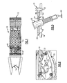
Figure 1 is a elevational view of a turbojet with multiple penetrations. -
Figure 2 is a perspective view of an angled seal assembly for an example penetrating element associated with one of the penetrations. -
Figure 3 is a cross-sectional view of the seal assembly shown inFigure 2 . -
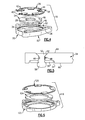
Figure 4 is an exploded view of the seal assembly shown inFigures 2 and 3 . -
Figure 5 is an enlarged cross-sectional view of a seal according to one example. -
Figure 6 is an exploded view of another example seal assembly. - A
turbojet engine 10 is shown inFigure 1 that includes aninlet 12 and an outlet 14.Bypass ducts 16 are arranged between theinlet 12 and outlet 14. Theducts 16 include multiple penetrations orapertures 18 that are configured to receive various penetrating elements, such as but not limited to oil lines, fuel lines, augmentor spray bars, engine igniters and boroscope plugs. Although aturbojet 10 is illustrated, it should be understood that other types of turbo machines or gas turbine engines may benefit from the disclosed seal assembly. - Referring to
Figures 2-4 , aseal assembly 19 is used to seal a penetratingelement 30 relative to thepenetration 18 in the duct. In the example shown, the penetratingelement 30 is a boroscope having a portion that is supported by acore 32. Thecore 32 houses various compressor and turbine stages, for example. - The
seal assembly 19 includes ahousing 20 secured to theduct 16 at anouter side 60 byfastening elements 22. Aseal 24 is supported relative to thehousing 20 at a recess in aninner side 62 using a retainer, such as aretaining ring 26, for example. In the example, theseal 24 has a generally circular perimeter and generally parallelopposing sides element 30 extends through an opening 28 in theseal 24, which is centrally located in the example. The perimeter seals to thehousing 20 and the penetrating element. Some penetrating elements may be positioned at an angle relative to theseal 24 such that theopening 28 is provided with a portion having an angledinner diameter surface 29 that is non-perpendicular to theopposing sides seal 24 is retained in a desired orientation relative to thehousing 20 by an anti-rotation feature to facilitate insertion of the penetratingelement 30 through theseal 24 during assembly. - The
housing 20 includes anannular groove 34 and anadjoining notch 36 used in the case of an angled penetration. Theretaining ring 26 is received in theannular groove 34 in an installed position. Atab 38 on theretaining ring 26 is received in thenotch 36.Ears 40 havingholes 42 facilitate installation of theretaining ring 26 into thegroove 34 using snap-ring pliers or similar tool, for example. - The
seal 24 includes ahole 46 receiving arivet 48. Theretaining ring 26 includes aslot 44 that receives therivet 48 to angularly locate theseal 24 relative to thehousing 20. Therivet 48 includes afrustoconical head 50, for example, received in a complementarilyshaped countersunk bore 52 of thehole 46 at afirst side 64 of theseal 24. Abore 54 is arranged on thesecond side 66 and receives awasher 56. Thewasher 56 receives anend 58 of therivet 48 that is plastically deformed when installing therivet 48 into theseal 24. Theend 58 is received in theslot 44. In one example, thebore 56 has a 0.355 - 0.365 inch (9.02 - 9.27 mm) outer diameter and approximately a 0.035 inch (0.89 mm) depth. Therivet 48, for example, includes a 0.096 - 0.100 inch (2.44 - 2.54 mm) diameter shank with a 0.165 - 0.175 inch (4.19 - 4.45 mm) x 100° ± 5°head 50. Thedeformed end 58 is approximately 0.118 - 0.140 inch (3.00 - 3.56 mm) in diameter and 0.060 - 0.100 inch (1.52 - 2.54 mm) in height. - The
seal 24 is constructed from a composite material, which is non-metallic in one example. In one example, the material is a composite laminate material including multiple layers bound together with a polymeric resin, such as a polymide. In one example, the layers are constructed from a carbon fiber woven fabric. In one example, thecomposite seal 24 is constructed using a material available from DuPont under the trade name CP-2015. Instead of using a pin as is typical for locating titanium sheet seals, therivet 48 andwasher 56 arrangement remains secured to theseal 24 in a desired manner during use despite any creep the seal material may experience. Theseal 24 is clamped securely between thewasher 56 and thehead 50 by thedeformed end 58. - Referring to
Figure 6 , a further embodiment ofseal assembly 119 is shown. This embodiment is generally similar to the embodiment ofFigures 2 to 5 except that theseal 124,housing 120 andretainer 126 do not incorporate the anti-rotation features described above. - Although example embodiments have been disclosed, a worker of ordinary skill in this art would recognize that certain modifications would come within the scope of the claims. For that reason, the following claims should be studied to determine their true scope and content.
Claims (15)
- A seal assembly (19; 119) for a turbo machine comprising:a housing (20; 120);a retainer (26; 126) secured relative to the housing (20; 120); anda seal (24; 124) arranged between the housing (20; 120) and retainer (26; 126), the seal (24; 124) providing an opening (28) configured to receive a penetrating element (30), the seal (24; 124) comprising a composite material.
- The seal assembly according to claim 1, wherein the composite material includes multiple layers of carbon fiber fabric laminated together with a resin.
- The seal assembly according to claim 1 or 2, wherein the opening (28) includes a surface having a portion (29) that is at an non-perpendicular angle relative to generally parallel opposing sides (64, 66) of the seal, and comprising an anti-rotation feature cooperating with at least one of the housing (20) and retainer (26) to maintain an angular position of the seal (24) relative to the housing (20).
- The seal assembly according to claim 3, wherein the anti-rotation feature includes a hole (46) in the seal (24), and comprising a rivet (48) arranged in the hole (46) cooperating with the at least one of the housing (20) and the retainer (26).
- The seal assembly according to claim 4, wherein the housing (20) includes a notch (36) and the retainer (26) includes a tab (38) received in the notch (36), the retainer (26) including a slot (44) with the rivet (48) received in the slot (44).
- The seal assembly according to claim 5, wherein the rivet (48) includes a plastically deformed end (58) received in the slot (44).
- The seal assembly according to claim 6, wherein the rivet (48) includes a head (50) on one side of the seal (24), and a washer (56) is arranged between an opposite side of the seal and the plastically deformed end (58), the seal (24) clamped between the washer (56) and the head (50).
- The seal assembly according to claim 7, wherein the hole (46) at the one side includes a countersunk bore (52), the head (50) of a generally complementary shape to the countersunk bore (52) and received therein.
- A seal (24; 124) for a gas turbine engine penetration seal assembly (19) comprising:a composite structure including carbon fiber fabric layers laminated with a resin, and an opening (28) configured to receive a penetrating element (30).
- The seal according to claim 9, wherein the composite structure includes generally parallel spaced apart sides (64, 66) and a generally circular perimeter, the opening (28) centrally located within the perimeter.
- The seal according to claim 10, wherein the composite structure includes a hole (46) spaced from the opening (28).
- A gas turbine engine (10) comprising:a core (32);a duct (16) surrounding the core (32) and having an aperture (18);a housing (20) secured to the duct (16) around the aperture (18);a seal (24) supported by the housing (20) and including an opening (28), the seal comprising a composite material; anda penetrating element (30) extending through the opening and supported by the core (32).
- The gas turbine engine according to claim 12, wherein the composite material includes multiple layers of carbon fiber fabric laminated together with a resin.
- The gas turbine engine according to claim 12 or 13, comprising a retainer (26) secured relative to the housing (20), wherein the opening (28) includes a surface having a portion (29) that is at an non-perpendicular angle relative to generally parallel opposing sides of the seal (24), and comprising an anti-rotation feature cooperating with at least one of the housing (20) and retainer (26) to maintain an angular position of the seal (24) relative to the housing (20).
- The gas turbine engine according to claim 12, 13 or 14 wherein the anti-rotation feature includes a hole (46) in the seal (24), and comprising a rivet (48) arranged in the hole (46) cooperating with the at least one of the housing (20) and the retainer (26), the rivet (48) includes a plastically deformed end (58), the rivet (48) includes a head (50) on one side of the seal (24), and a washer (56) is arranged between an opposite side of the seal (24) and the plastically deformed end (58), the seal (24) clamped between the washer (56) and the head (50), and wherein, optionally, the housing (20) includes a notch (36) and the retainer (26) includes a tab (38) received in the notch (30), the retainer (26) including a slot (44) with the rivet (45) received in the slot (44).
Applications Claiming Priority (1)
| Application Number | Priority Date | Filing Date | Title |
|---|---|---|---|
| US12/625,704 US8523514B2 (en) | 2009-11-25 | 2009-11-25 | Composite slider seal for turbojet penetration |
Publications (3)
| Publication Number | Publication Date |
|---|---|
| EP2327858A2 true EP2327858A2 (en) | 2011-06-01 |
| EP2327858A3 EP2327858A3 (en) | 2012-02-08 |
| EP2327858B1 EP2327858B1 (en) | 2019-01-30 |
Family
ID=43611337
Family Applications (1)
| Application Number | Title | Priority Date | Filing Date |
|---|---|---|---|
| EP10251996.4A Active EP2327858B1 (en) | 2009-11-25 | 2010-11-24 | Composite slider seal |
Country Status (2)
| Country | Link |
|---|---|
| US (1) | US8523514B2 (en) |
| EP (1) | EP2327858B1 (en) |
Cited By (4)
| Publication number | Priority date | Publication date | Assignee | Title |
|---|---|---|---|---|
| FR3018114A1 (en) * | 2014-03-03 | 2015-09-04 | Turbomeca | DEVICE FOR POSITIONING AN INSPECTION TOOL |
| EP3222821A1 (en) * | 2016-03-22 | 2017-09-27 | United Technologies Corporation | Anti-rotation shim seal |
| EP3699400A1 (en) * | 2019-01-29 | 2020-08-26 | United Technologies Corporation | Light weight low blockage slider seal |
| EP3770504A1 (en) * | 2019-07-26 | 2021-01-27 | Raytheon Technologies Corporation | Slider seal with non-circular puck geometry |
Families Citing this family (9)
| Publication number | Priority date | Publication date | Assignee | Title |
|---|---|---|---|---|
| US8196934B2 (en) * | 2007-01-10 | 2012-06-12 | United Technologies Corporation | Slider seal assembly for gas turbine engine |
| US20110089645A1 (en) | 2010-12-20 | 2011-04-21 | White Drew K | Underwater swimming pool light repair device |
| US9765649B2 (en) * | 2013-05-08 | 2017-09-19 | United Technologies Corporation | Borescope inspection port fitting |
| US9909458B2 (en) * | 2014-05-22 | 2018-03-06 | United Technologies Corporation | Instrumentation boss for fan containment case |
| US9874108B2 (en) | 2014-07-08 | 2018-01-23 | Rolls-Royce Corporation | Cleaning system for a turbofan gas turbine engine |
| US9657590B2 (en) | 2014-08-04 | 2017-05-23 | Rolls-Royce Corporation | Aircraft engine cleaning system |
| US9821349B2 (en) | 2014-09-10 | 2017-11-21 | Rolls-Royce Corporation | Wands for gas turbine engine cleaning |
| US9835048B2 (en) | 2014-12-03 | 2017-12-05 | Rolls-Royce Corporation | Turbine engine fleet wash management system |
| US11828394B2 (en) * | 2018-07-05 | 2023-11-28 | Durr UNIVERSAL, Inc. | Expansion and movement joints |
Family Cites Families (22)
| Publication number | Priority date | Publication date | Assignee | Title |
|---|---|---|---|---|
| US3000846A (en) | 1957-11-19 | 1961-09-19 | Russell Mfg Co | High temperature molded fabric packing gland |
| US3793838A (en) | 1972-09-05 | 1974-02-26 | Gen Electric | Augmenter fuel injection mounting system |
| GB1602836A (en) | 1977-05-11 | 1981-11-18 | Lucas Industries Ltd | Sealing arrangement for use in a combustion assembly |
| US4214761A (en) | 1978-07-31 | 1980-07-29 | Utex Industries, Inc. | Packing construction |
| US4591794A (en) | 1982-12-28 | 1986-05-27 | United Technologies Corporation | Gas turbine access port plug electrostatic probe |
| US5104286A (en) | 1991-02-08 | 1992-04-14 | Westinghouse Electric Corp. | Recirculation seal for a gas turbine exhaust diffuser |
| DE4237886A1 (en) | 1992-09-11 | 1994-03-17 | Mtu Muenchen Gmbh | Device for sealing fluidically differently pressurized spaces between housings which can move relative to one another, in particular aircraft engines |
| US5836048A (en) | 1996-08-09 | 1998-11-17 | Mcdonnell Douglas Corporation | Universal fire barrier grommet |
| GB0219458D0 (en) | 2002-08-21 | 2002-09-25 | Rolls Royce Plc | Fuel injection apparatus |
| US6968695B2 (en) | 2002-09-13 | 2005-11-29 | The Boeing Company | Compact lightweight ramjet engines incorporating swirl augmented combustion with improved performance |
| US6942452B2 (en) | 2002-12-17 | 2005-09-13 | Pratt & Whitney Canada Corp. | Grommeted bypass duct penetration |
| JP2004205003A (en) | 2002-12-26 | 2004-07-22 | Ntn Corp | Resin seal ring and method of manufacturing the same |
| FR2852003B1 (en) | 2003-03-04 | 2005-05-27 | Snecma Propulsion Solide | PROCESS FOR PRODUCING A MULTIPERFORATED PART IN CERAMIC MATRIX COMPOSITE MATERIAL |
| JP4676333B2 (en) | 2003-04-02 | 2011-04-27 | 株式会社リケン | Seal ring |
| DE20311346U1 (en) | 2003-07-23 | 2003-10-02 | Burgmann Dichtungswerke GmbH & Co. KG, 82515 Wolfratshausen | For a common rotation with an engine shaft designed sliding ring of a mechanical seal arrangement for jet engines |
| DE10347080A1 (en) | 2003-10-10 | 2005-05-12 | Frenzelit Werke Gmbh & Co Kg | Flat sealing material in the form of a fiber-reinforced foil |
| US7249929B2 (en) | 2003-11-13 | 2007-07-31 | United Technologies Corporation | Bleed housing |
| US7540501B2 (en) | 2004-11-05 | 2009-06-02 | Flowserve Management Company | Segmented shaft seal |
| JP4250585B2 (en) | 2004-12-07 | 2009-04-08 | 日本ピラー工業株式会社 | Mechanical seal device |
| US7434383B2 (en) | 2005-05-12 | 2008-10-14 | Honeywell International Inc. | Bypass duct boss repair technology |
| JP2007090133A (en) | 2005-09-27 | 2007-04-12 | Shigemitsu Kawazoe | Sealing equipment for painting equipment |
| US8196934B2 (en) * | 2007-01-10 | 2012-06-12 | United Technologies Corporation | Slider seal assembly for gas turbine engine |
-
2009
- 2009-11-25 US US12/625,704 patent/US8523514B2/en active Active
-
2010
- 2010-11-24 EP EP10251996.4A patent/EP2327858B1/en active Active
Non-Patent Citations (1)
| Title |
|---|
| None |
Cited By (6)
| Publication number | Priority date | Publication date | Assignee | Title |
|---|---|---|---|---|
| FR3018114A1 (en) * | 2014-03-03 | 2015-09-04 | Turbomeca | DEVICE FOR POSITIONING AN INSPECTION TOOL |
| WO2015132505A1 (en) * | 2014-03-03 | 2015-09-11 | Turbomeca | Device for positioning an inspection tool |
| EP3222821A1 (en) * | 2016-03-22 | 2017-09-27 | United Technologies Corporation | Anti-rotation shim seal |
| US10450882B2 (en) | 2016-03-22 | 2019-10-22 | United Technologies Corporation | Anti-rotation shim seal |
| EP3699400A1 (en) * | 2019-01-29 | 2020-08-26 | United Technologies Corporation | Light weight low blockage slider seal |
| EP3770504A1 (en) * | 2019-07-26 | 2021-01-27 | Raytheon Technologies Corporation | Slider seal with non-circular puck geometry |
Also Published As
| Publication number | Publication date |
|---|---|
| US8523514B2 (en) | 2013-09-03 |
| US20110123319A1 (en) | 2011-05-26 |
| EP2327858B1 (en) | 2019-01-30 |
| EP2327858A3 (en) | 2012-02-08 |
Similar Documents
| Publication | Publication Date | Title |
|---|---|---|
| EP2327858B1 (en) | Composite slider seal | |
| US11879349B2 (en) | Shroud hanger assembly | |
| US8418473B2 (en) | Pivoting liner hanger | |
| US7556475B2 (en) | Methods and apparatus for assembling turbine engines | |
| US8864450B2 (en) | Gas turbine engine synchronizing ring bumper | |
| EP2824286B1 (en) | Gas turbine engine synchronizing ring bumper | |
| JP2006266669A (en) | Bearing plate assembly, swivel assembly, bearing plate for fuel injector assembly, swivel and nozzle tip bushing | |
| JP5852249B2 (en) | gas turbine | |
| EP2278226B1 (en) | Fuel nozzle guide plate mistake proofing | |
| US8876478B2 (en) | Turbine blade combined damper and sealing pin and related method | |
| US9021812B2 (en) | Combustor dome and heat-shield assembly | |
| US6655912B2 (en) | Guide vane stage of a compressor | |
| US8973375B2 (en) | Shielding for a gas turbine engine component | |
| US11028709B2 (en) | Airfoil shroud assembly using tenon with externally threaded stud and nut | |
| EP3219909B1 (en) | Disc for a gas turbine engine, rotor assembly, and gas turbine | |
| EP3825520A1 (en) | Vane for gas turbine engine | |
| EP4641091A1 (en) | Gas turbine combustor | |
| EP3438410B1 (en) | Sealing system for a rotary machine | |
| US9133724B2 (en) | Turbomachine component including a cover plate | |
| CN114576008B (en) | Aeroengine casing and aeroengine | |
| EP2530385A2 (en) | Turbomachine combustor assembly including a liner stop | |
| US12460727B2 (en) | Self-centering seal and method of using same | |
| GB2384829A (en) | Casing arrangement | |
| US20170268351A1 (en) | Retaining ring groove submerged into disc bore or hub | |
| EP4678901A3 (en) | Gas turbine engine with integral actuation system |
Legal Events
| Date | Code | Title | Description |
|---|---|---|---|
| PUAI | Public reference made under article 153(3) epc to a published international application that has entered the european phase |
Free format text: ORIGINAL CODE: 0009012 |
|
| AK | Designated contracting states |
Kind code of ref document: A2 Designated state(s): AL AT BE BG CH CY CZ DE DK EE ES FI FR GB GR HR HU IE IS IT LI LT LU LV MC MK MT NL NO PL PT RO RS SE SI SK SM TR |
|
| AX | Request for extension of the european patent |
Extension state: BA ME |
|
| RIC1 | Information provided on ipc code assigned before grant |
Ipc: F16J 15/44 20060101ALI20111015BHEP Ipc: F16J 15/16 20060101ALI20111015BHEP Ipc: F02C 7/28 20060101ALI20111015BHEP Ipc: F01D 21/00 20060101ALI20111015BHEP Ipc: F01D 11/00 20060101AFI20111015BHEP |
|
| PUAL | Search report despatched |
Free format text: ORIGINAL CODE: 0009013 |
|
| AK | Designated contracting states |
Kind code of ref document: A3 Designated state(s): AL AT BE BG CH CY CZ DE DK EE ES FI FR GB GR HR HU IE IS IT LI LT LU LV MC MK MT NL NO PL PT RO RS SE SI SK SM TR |
|
| AX | Request for extension of the european patent |
Extension state: BA ME |
|
| RIC1 | Information provided on ipc code assigned before grant |
Ipc: F02C 7/28 20060101ALI20120105BHEP Ipc: F01D 11/00 20060101AFI20120105BHEP Ipc: F16J 15/16 20060101ALI20120105BHEP Ipc: F01D 21/00 20060101ALI20120105BHEP Ipc: F16J 15/44 20060101ALI20120105BHEP |
|
| 17P | Request for examination filed |
Effective date: 20120807 |
|
| RAP1 | Party data changed (applicant data changed or rights of an application transferred) |
Owner name: UNITED TECHNOLOGIES CORPORATION |
|
| STAA | Information on the status of an ep patent application or granted ep patent |
Free format text: STATUS: EXAMINATION IS IN PROGRESS |
|
| 17Q | First examination report despatched |
Effective date: 20170721 |
|
| GRAP | Despatch of communication of intention to grant a patent |
Free format text: ORIGINAL CODE: EPIDOSNIGR1 |
|
| STAA | Information on the status of an ep patent application or granted ep patent |
Free format text: STATUS: GRANT OF PATENT IS INTENDED |
|
| INTG | Intention to grant announced |
Effective date: 20180801 |
|
| GRAJ | Information related to disapproval of communication of intention to grant by the applicant or resumption of examination proceedings by the epo deleted |
Free format text: ORIGINAL CODE: EPIDOSDIGR1 |
|
| STAA | Information on the status of an ep patent application or granted ep patent |
Free format text: STATUS: EXAMINATION IS IN PROGRESS |
|
| GRAR | Information related to intention to grant a patent recorded |
Free format text: ORIGINAL CODE: EPIDOSNIGR71 |
|
| GRAS | Grant fee paid |
Free format text: ORIGINAL CODE: EPIDOSNIGR3 |
|
| STAA | Information on the status of an ep patent application or granted ep patent |
Free format text: STATUS: GRANT OF PATENT IS INTENDED |
|
| GRAA | (expected) grant |
Free format text: ORIGINAL CODE: 0009210 |
|
| STAA | Information on the status of an ep patent application or granted ep patent |
Free format text: STATUS: THE PATENT HAS BEEN GRANTED |
|
| INTC | Intention to grant announced (deleted) | ||
| AK | Designated contracting states |
Kind code of ref document: B1 Designated state(s): AL AT BE BG CH CY CZ DE DK EE ES FI FR GB GR HR HU IE IS IT LI LT LU LV MC MK MT NL NO PL PT RO RS SE SI SK SM TR |
|
| INTG | Intention to grant announced |
Effective date: 20181221 |
|
| REG | Reference to a national code |
Ref country code: GB Ref legal event code: FG4D |
|
| REG | Reference to a national code |
Ref country code: CH Ref legal event code: EP |
|
| REG | Reference to a national code |
Ref country code: AT Ref legal event code: REF Ref document number: 1093437 Country of ref document: AT Kind code of ref document: T Effective date: 20190215 |
|
| REG | Reference to a national code |
Ref country code: IE Ref legal event code: FG4D |
|
| REG | Reference to a national code |
Ref country code: DE Ref legal event code: R096 Ref document number: 602010056839 Country of ref document: DE |
|
| REG | Reference to a national code |
Ref country code: LT Ref legal event code: MG4D |
|
| REG | Reference to a national code |
Ref country code: NL Ref legal event code: MP Effective date: 20190130 |
|
| PG25 | Lapsed in a contracting state [announced via postgrant information from national office to epo] |
Ref country code: PT Free format text: LAPSE BECAUSE OF FAILURE TO SUBMIT A TRANSLATION OF THE DESCRIPTION OR TO PAY THE FEE WITHIN THE PRESCRIBED TIME-LIMIT Effective date: 20190530 Ref country code: FI Free format text: LAPSE BECAUSE OF FAILURE TO SUBMIT A TRANSLATION OF THE DESCRIPTION OR TO PAY THE FEE WITHIN THE PRESCRIBED TIME-LIMIT Effective date: 20190130 Ref country code: LT Free format text: LAPSE BECAUSE OF FAILURE TO SUBMIT A TRANSLATION OF THE DESCRIPTION OR TO PAY THE FEE WITHIN THE PRESCRIBED TIME-LIMIT Effective date: 20190130 Ref country code: PL Free format text: LAPSE BECAUSE OF FAILURE TO SUBMIT A TRANSLATION OF THE DESCRIPTION OR TO PAY THE FEE WITHIN THE PRESCRIBED TIME-LIMIT Effective date: 20190130 Ref country code: NL Free format text: LAPSE BECAUSE OF FAILURE TO SUBMIT A TRANSLATION OF THE DESCRIPTION OR TO PAY THE FEE WITHIN THE PRESCRIBED TIME-LIMIT Effective date: 20190130 Ref country code: SE Free format text: LAPSE BECAUSE OF FAILURE TO SUBMIT A TRANSLATION OF THE DESCRIPTION OR TO PAY THE FEE WITHIN THE PRESCRIBED TIME-LIMIT Effective date: 20190130 Ref country code: NO Free format text: LAPSE BECAUSE OF FAILURE TO SUBMIT A TRANSLATION OF THE DESCRIPTION OR TO PAY THE FEE WITHIN THE PRESCRIBED TIME-LIMIT Effective date: 20190430 Ref country code: ES Free format text: LAPSE BECAUSE OF FAILURE TO SUBMIT A TRANSLATION OF THE DESCRIPTION OR TO PAY THE FEE WITHIN THE PRESCRIBED TIME-LIMIT Effective date: 20190130 |
|
| REG | Reference to a national code |
Ref country code: AT Ref legal event code: MK05 Ref document number: 1093437 Country of ref document: AT Kind code of ref document: T Effective date: 20190130 |
|
| PG25 | Lapsed in a contracting state [announced via postgrant information from national office to epo] |
Ref country code: HR Free format text: LAPSE BECAUSE OF FAILURE TO SUBMIT A TRANSLATION OF THE DESCRIPTION OR TO PAY THE FEE WITHIN THE PRESCRIBED TIME-LIMIT Effective date: 20190130 Ref country code: LV Free format text: LAPSE BECAUSE OF FAILURE TO SUBMIT A TRANSLATION OF THE DESCRIPTION OR TO PAY THE FEE WITHIN THE PRESCRIBED TIME-LIMIT Effective date: 20190130 Ref country code: GR Free format text: LAPSE BECAUSE OF FAILURE TO SUBMIT A TRANSLATION OF THE DESCRIPTION OR TO PAY THE FEE WITHIN THE PRESCRIBED TIME-LIMIT Effective date: 20190501 Ref country code: IS Free format text: LAPSE BECAUSE OF FAILURE TO SUBMIT A TRANSLATION OF THE DESCRIPTION OR TO PAY THE FEE WITHIN THE PRESCRIBED TIME-LIMIT Effective date: 20190530 Ref country code: RS Free format text: LAPSE BECAUSE OF FAILURE TO SUBMIT A TRANSLATION OF THE DESCRIPTION OR TO PAY THE FEE WITHIN THE PRESCRIBED TIME-LIMIT Effective date: 20190130 Ref country code: BG Free format text: LAPSE BECAUSE OF FAILURE TO SUBMIT A TRANSLATION OF THE DESCRIPTION OR TO PAY THE FEE WITHIN THE PRESCRIBED TIME-LIMIT Effective date: 20190430 |
|
| PG25 | Lapsed in a contracting state [announced via postgrant information from national office to epo] |
Ref country code: EE Free format text: LAPSE BECAUSE OF FAILURE TO SUBMIT A TRANSLATION OF THE DESCRIPTION OR TO PAY THE FEE WITHIN THE PRESCRIBED TIME-LIMIT Effective date: 20190130 Ref country code: IT Free format text: LAPSE BECAUSE OF FAILURE TO SUBMIT A TRANSLATION OF THE DESCRIPTION OR TO PAY THE FEE WITHIN THE PRESCRIBED TIME-LIMIT Effective date: 20190130 Ref country code: CZ Free format text: LAPSE BECAUSE OF FAILURE TO SUBMIT A TRANSLATION OF THE DESCRIPTION OR TO PAY THE FEE WITHIN THE PRESCRIBED TIME-LIMIT Effective date: 20190130 Ref country code: RO Free format text: LAPSE BECAUSE OF FAILURE TO SUBMIT A TRANSLATION OF THE DESCRIPTION OR TO PAY THE FEE WITHIN THE PRESCRIBED TIME-LIMIT Effective date: 20190130 Ref country code: AL Free format text: LAPSE BECAUSE OF FAILURE TO SUBMIT A TRANSLATION OF THE DESCRIPTION OR TO PAY THE FEE WITHIN THE PRESCRIBED TIME-LIMIT Effective date: 20190130 Ref country code: DK Free format text: LAPSE BECAUSE OF FAILURE TO SUBMIT A TRANSLATION OF THE DESCRIPTION OR TO PAY THE FEE WITHIN THE PRESCRIBED TIME-LIMIT Effective date: 20190130 Ref country code: SK Free format text: LAPSE BECAUSE OF FAILURE TO SUBMIT A TRANSLATION OF THE DESCRIPTION OR TO PAY THE FEE WITHIN THE PRESCRIBED TIME-LIMIT Effective date: 20190130 |
|
| REG | Reference to a national code |
Ref country code: DE Ref legal event code: R097 Ref document number: 602010056839 Country of ref document: DE |
|
| PG25 | Lapsed in a contracting state [announced via postgrant information from national office to epo] |
Ref country code: SM Free format text: LAPSE BECAUSE OF FAILURE TO SUBMIT A TRANSLATION OF THE DESCRIPTION OR TO PAY THE FEE WITHIN THE PRESCRIBED TIME-LIMIT Effective date: 20190130 |
|
| PLBE | No opposition filed within time limit |
Free format text: ORIGINAL CODE: 0009261 |
|
| STAA | Information on the status of an ep patent application or granted ep patent |
Free format text: STATUS: NO OPPOSITION FILED WITHIN TIME LIMIT |
|
| PG25 | Lapsed in a contracting state [announced via postgrant information from national office to epo] |
Ref country code: AT Free format text: LAPSE BECAUSE OF FAILURE TO SUBMIT A TRANSLATION OF THE DESCRIPTION OR TO PAY THE FEE WITHIN THE PRESCRIBED TIME-LIMIT Effective date: 20190130 |
|
| 26N | No opposition filed |
Effective date: 20191031 |
|
| PG25 | Lapsed in a contracting state [announced via postgrant information from national office to epo] |
Ref country code: SI Free format text: LAPSE BECAUSE OF FAILURE TO SUBMIT A TRANSLATION OF THE DESCRIPTION OR TO PAY THE FEE WITHIN THE PRESCRIBED TIME-LIMIT Effective date: 20190130 |
|
| PG25 | Lapsed in a contracting state [announced via postgrant information from national office to epo] |
Ref country code: TR Free format text: LAPSE BECAUSE OF FAILURE TO SUBMIT A TRANSLATION OF THE DESCRIPTION OR TO PAY THE FEE WITHIN THE PRESCRIBED TIME-LIMIT Effective date: 20190130 |
|
| REG | Reference to a national code |
Ref country code: CH Ref legal event code: PL |
|
| PG25 | Lapsed in a contracting state [announced via postgrant information from national office to epo] |
Ref country code: MC Free format text: LAPSE BECAUSE OF FAILURE TO SUBMIT A TRANSLATION OF THE DESCRIPTION OR TO PAY THE FEE WITHIN THE PRESCRIBED TIME-LIMIT Effective date: 20190130 Ref country code: CH Free format text: LAPSE BECAUSE OF NON-PAYMENT OF DUE FEES Effective date: 20191130 Ref country code: LI Free format text: LAPSE BECAUSE OF NON-PAYMENT OF DUE FEES Effective date: 20191130 Ref country code: LU Free format text: LAPSE BECAUSE OF NON-PAYMENT OF DUE FEES Effective date: 20191124 |
|
| REG | Reference to a national code |
Ref country code: BE Ref legal event code: MM Effective date: 20191130 |
|
| PG25 | Lapsed in a contracting state [announced via postgrant information from national office to epo] |
Ref country code: IE Free format text: LAPSE BECAUSE OF NON-PAYMENT OF DUE FEES Effective date: 20191124 |
|
| PG25 | Lapsed in a contracting state [announced via postgrant information from national office to epo] |
Ref country code: BE Free format text: LAPSE BECAUSE OF NON-PAYMENT OF DUE FEES Effective date: 20191130 |
|
| PG25 | Lapsed in a contracting state [announced via postgrant information from national office to epo] |
Ref country code: CY Free format text: LAPSE BECAUSE OF FAILURE TO SUBMIT A TRANSLATION OF THE DESCRIPTION OR TO PAY THE FEE WITHIN THE PRESCRIBED TIME-LIMIT Effective date: 20190130 |
|
| PG25 | Lapsed in a contracting state [announced via postgrant information from national office to epo] |
Ref country code: HU Free format text: LAPSE BECAUSE OF FAILURE TO SUBMIT A TRANSLATION OF THE DESCRIPTION OR TO PAY THE FEE WITHIN THE PRESCRIBED TIME-LIMIT; INVALID AB INITIO Effective date: 20101124 Ref country code: MT Free format text: LAPSE BECAUSE OF FAILURE TO SUBMIT A TRANSLATION OF THE DESCRIPTION OR TO PAY THE FEE WITHIN THE PRESCRIBED TIME-LIMIT Effective date: 20190130 |
|
| PG25 | Lapsed in a contracting state [announced via postgrant information from national office to epo] |
Ref country code: MK Free format text: LAPSE BECAUSE OF FAILURE TO SUBMIT A TRANSLATION OF THE DESCRIPTION OR TO PAY THE FEE WITHIN THE PRESCRIBED TIME-LIMIT Effective date: 20190130 |
|
| REG | Reference to a national code |
Ref country code: DE Ref legal event code: R081 Ref document number: 602010056839 Country of ref document: DE Owner name: RAYTHEON TECHNOLOGIES CORPORATION (N.D.GES.D.S, US Free format text: FORMER OWNER: UNITED TECHNOLOGIES CORPORATION, FARMINGTON, CONN., US Ref country code: DE Ref legal event code: R081 Ref document number: 602010056839 Country of ref document: DE Owner name: RTX CORPORATION (N.D.GES.D. STAATES DELAWARE),, US Free format text: FORMER OWNER: UNITED TECHNOLOGIES CORPORATION, FARMINGTON, CONN., US |
|
| P01 | Opt-out of the competence of the unified patent court (upc) registered |
Effective date: 20230519 |
|
| REG | Reference to a national code |
Ref country code: DE Ref legal event code: R081 Ref document number: 602010056839 Country of ref document: DE Owner name: RTX CORPORATION (N.D.GES.D. STAATES DELAWARE),, US Free format text: FORMER OWNER: RAYTHEON TECHNOLOGIES CORPORATION (N.D.GES.D.STAATES DELAWARE), ARLINGTON, VA, US |
|
| PGFP | Annual fee paid to national office [announced via postgrant information from national office to epo] |
Ref country code: DE Payment date: 20251022 Year of fee payment: 16 |
|
| PGFP | Annual fee paid to national office [announced via postgrant information from national office to epo] |
Ref country code: GB Payment date: 20251023 Year of fee payment: 16 |
|
| PGFP | Annual fee paid to national office [announced via postgrant information from national office to epo] |
Ref country code: FR Payment date: 20251022 Year of fee payment: 16 |