EP2327363A1 - Ultrasound system and method for providing change trend image - Google Patents
Ultrasound system and method for providing change trend image Download PDFInfo
- Publication number
- EP2327363A1 EP2327363A1 EP20100192778 EP10192778A EP2327363A1 EP 2327363 A1 EP2327363 A1 EP 2327363A1 EP 20100192778 EP20100192778 EP 20100192778 EP 10192778 A EP10192778 A EP 10192778A EP 2327363 A1 EP2327363 A1 EP 2327363A1
- Authority
- EP
- European Patent Office
- Prior art keywords
- ultrasound
- values
- value
- brightness
- change trend
- Prior art date
- Legal status (The legal status is an assumption and is not a legal conclusion. Google has not performed a legal analysis and makes no representation as to the accuracy of the status listed.)
- Withdrawn
Links
Images



Classifications
-
- A—HUMAN NECESSITIES
- A61—MEDICAL OR VETERINARY SCIENCE; HYGIENE
- A61B—DIAGNOSIS; SURGERY; IDENTIFICATION
- A61B8/00—Diagnosis using ultrasonic, sonic or infrasonic waves
-
- A—HUMAN NECESSITIES
- A61—MEDICAL OR VETERINARY SCIENCE; HYGIENE
- A61B—DIAGNOSIS; SURGERY; IDENTIFICATION
- A61B8/00—Diagnosis using ultrasonic, sonic or infrasonic waves
- A61B8/13—Tomography
- A61B8/14—Echo-tomography
-
- G—PHYSICS
- G01—MEASURING; TESTING
- G01S—RADIO DIRECTION-FINDING; RADIO NAVIGATION; DETERMINING DISTANCE OR VELOCITY BY USE OF RADIO WAVES; LOCATING OR PRESENCE-DETECTING BY USE OF THE REFLECTION OR RERADIATION OF RADIO WAVES; ANALOGOUS ARRANGEMENTS USING OTHER WAVES
- G01S7/00—Details of systems according to groups G01S13/00, G01S15/00, G01S17/00
- G01S7/52—Details of systems according to groups G01S13/00, G01S15/00, G01S17/00 of systems according to group G01S15/00
- G01S7/52017—Details of systems according to groups G01S13/00, G01S15/00, G01S17/00 of systems according to group G01S15/00 particularly adapted to short-range imaging
- G01S7/52053—Display arrangements
- G01S7/52057—Cathode ray tube displays
- G01S7/52071—Multicolour displays; using colour coding; Optimising colour or information content in displays, e.g. parametric imaging
-
- A—HUMAN NECESSITIES
- A61—MEDICAL OR VETERINARY SCIENCE; HYGIENE
- A61B—DIAGNOSIS; SURGERY; IDENTIFICATION
- A61B8/00—Diagnosis using ultrasonic, sonic or infrasonic waves
- A61B8/46—Ultrasonic, sonic or infrasonic diagnostic devices with special arrangements for interfacing with the operator or the patient
- A61B8/461—Displaying means of special interest
Definitions
- the present invention generally relates to ultrasound systems, and more particularly to an ultrasound system and method for providing a change trend image with colors.
- An ultrasound system has become an important and popular diagnostic tool due to its non-invasive and non-destructive nature.
- the ultrasound system can provide high dimensional real-time ultrasound images of inner parts of target objects without a surgical operation.
- the ultrasound system transmits ultrasound signals to the target objects, receives echo signals reflected from the target objects and provides ultrasound images of the target objects based on the echo signals.
- the ultrasound system may perform transmitting and receiving of ultrasound signals sequentially and iteratively to thereby form a plurality of ultrasound images.
- the plurality of ultrasound images may be sequentially displayed on a display unit. Further, the ultrasound system may synthesize the plurality of ultrasound images to form a synthesis image for image enhancement. The synthesis image may also be displayed on the display unit. In such a case, since the ultrasound images and the synthesis image are sequentially displayed one by one on the display unit, it may be difficult to intuitively recognize the change of a specific feature such as a brightness change over time at a specific region in the ultrasound images.
- an ultrasound system includes: an ultrasound data acquisition unit configured to transmit ultrasound signal to a target object and receive echo signal reflected from the target object to sequentially acquire a plurality of ultrasound data; and a processor connected to the ultrasound data acquisition unit, the processor being configured to sequentially extract feature values from the plurality of ultrasound data, allocate colors corresponding to each feature value and form a change trend image with the colors indicative of a change trend of the extracted feature values over time.
- a method of providing a change trend image comprises: transmitting ultrasound signal to a target object and receiving echo signal reflected from the target object to sequentially acquire a plurality of ultrasound data; sequentially extracting feature values from the plurality of ultrasound data; allocating colors corresponding to each feature value; and forming a change trend image with the colors indicative of a change trend of the extracted feature values over time.
- FIG. 1 is a block diagram showing an illustrative embodiment of an ultrasound system.
- the ultrasound system 100 includes an ultrasound data acquisition unit 110, a processor 120, a memory 130 and a display unit 140.
- the ultrasound data acquisition unit 110 is configured to transmit and receive ultrasound signals to and from a target object to thereby output ultrasound data of the target object.
- the ultrasound data acquisition unit 110 is explained more particularly by referring to FIG. 2 .
- FIG. 2 is a block diagram showing an illustrative embodiment of the ultrasound data acquisition unit 110.
- the ultrasound data acquisition unit 110 includes a transmit (Tx) signal generating section 111, an ultrasound probe 112 having a plurality of transducer elements (not shown), a beam former 113 and an ultrasound data forming section 114.
- Tx transmit
- the ultrasound data acquisition unit 110 includes a transmit (Tx) signal generating section 111, an ultrasound probe 112 having a plurality of transducer elements (not shown), a beam former 113 and an ultrasound data forming section 114.
- the Tx signal generating section 111 is configured to generate Tx signals.
- the Tx signal generating section 111 generates a plurality of Tx signals and apply delays to the Tx signals in consideration of distances between the respective transducer elements and focal points for acquiring ultrasound images indicative of the target object.
- the ultrasound images includes a brightness mode (B-mode) image, a Doppler mode (D-mode) image, a color mode (C-mode) image and a three-dimensional mode (3D mode) image.
- the B-mode image represents a two-dimensional ultrasound image with brightness, which is determined according to reflection coefficients of the ultrasound signals reflected from the target object.
- the D-mode image represents a Doppler spectrum image indicative of velocities of a moving target object, which may be measured over time by using the Doppler Effect.
- the C-mode image represents an image showing velocities of moving object, which may be measured by using the Doppler Effect, with predetermined colors.
- the 3D mode image represents a three-dimensional ultrasound image indicative of the target object, which may be formed by using reflection coefficients of the ultrasound signals reflected from the target object.
- the Tx signal generating section 111 generates the Tx signals sequentially and iteratively.
- the ultrasound probe 112 includes the plurality of transducer elements for reciprocally converting between ultrasound signals and electrical signals.
- the ultrasound probe 112 is configured to transmit ultrasound signals to the target object in response to the Tx signals provided from the Tx signal generating section 111.
- the ultrasound probe 112 further receives ultrasound echo signals reflected from the target object to thereby output the received signals.
- the received signals are analog signals.
- the ultrasound probe 112 forms a plurality of received signals by transmitting and receiving ultrasound signals sequentially and iteratively to and from the target object based on the Tx signals.
- the ultrasound probe 112 includes a three-dimensional (3D) mechanical probe, a two-dimensional (2D) array probe and the like. However, it should be noted herein that the ultrasound probe 112 is not limited thereto.
- the beam former 113 is configured to convert the received signals provided from the ultrasound probe 112 into digital signals.
- the beam former 113 further applies delays to the digital signals in consideration of distances between the transducer elements and focal points to thereby output digital receive-focused signals.
- the receive-focusing and the delay application upon the plurality of received signals are carried out sequentially and iteratively.
- the ultrasound data forming section 114 is configured to form ultrasound data corresponding to each of the plurality of ultrasound images based on the digital receive-focused signals provided from the beam former 113.
- the ultrasound data forming section 114 forms a plurality of ultrasound data sequentially and iteratively based on the plurality of digital receive-focused signals.
- the plurality of ultrasound data are radio frequency (RF) data.
- RF radio frequency
- the ultrasound data forming section 114 further performs various signal processing (e.g., gain adjustment) upon the digital receive-focused signals.
- the processor 120 is connected to the ultrasound data acquisition unit 110.
- the processor 120 forms a plurality of ultrasound images based on the plurality of ultrasound data sequentially provided from the ultrasound data acquisition unit 110.
- the processor 120 extracts specific feature values from the plurality of ultrasound images to obtain a change trend of the specific feature values over time.
- the specific feature values includes at least one of a maximum brightness value, a normalized value of minimum index, an average brightness value, a normalization function obtained by normalizing an accumulated function of brightness values, first index information on brightness values over a predetermined critical value, a dispersion of brightness values, a standard deviation of brightness values, a skewness of brightness values, a kurtosis of brightness values, a minimum brightness value, a brightness value of an N th ultrasound image, wherein N is a natural number, a orientation change function of a brightness value gradient and a phase change function of the brightness value gradient.
- the feature values include the maximum brightness value, the normalized value of minimum index and the average brightness value.
- the processor 120 forms a change trend image showing the extracted feature values with colors over time.
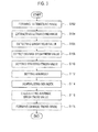
- FIG. 3 is a flowchart showing a process of forming a change trend image over time based on the extracted feature values.
- the processor 120 forms the ultrasound images including index information based on the ultrasound data provided from the ultrasound data acquisition section 110, at step S102.
- the index information includes information on a formation time of each of the ultrasound images or a serial number indicating a formation order of each of the ultrasound images.
- the processor 120 sequentially and iteratively forms a plurality of ultrasound images based on the ultrasound data sequentially provided from the ultrasound data acquisition section 110.
- the ultrasound images formed at the processor 120 are sequentially stored in the memory 130, as shown in FIG. 4 .
- FIG. 4 is a schematic diagram showing information on feature values from a plurality of ultrasound images including brightness values, maximum brightness values, minimum indexes, minimum index normalized values and average brightness values.
- the processor 120 extracts the plurality of ultrasound images from the memory 130, at step S104.
- the processor extracts the ultrasound images from the first stored ultrasound image U 1 to the lately stored ultrasound image U 8 , as shown in FIG. 4 .
- the processor 120 detects the brightness value (I(p)) of any position (p) of the ultrasound images, at step 5106.
- the processor 120 detects the I(p) "20", “10", “10”, “10”, “30”, “200”, “200” and "190”at p in the ultrasound images U 1 -U8, as shown in FIG. 4 .
- the p denotes a position of an arbitrary pixel in the two-dimensional ultrasound image such as the B-mode ultrasound image, the D-mode ultrasound image and the C-mode ultrasound image, and denote a position of an arbitrary voxel in the three-dimensional ultrasound image such as the 3D mode ultrasound image.
- the processor 120 Since the brightness value "20" of the position "p” of the ultrasound image U 2 is smaller than the I max (p), the processor 120 sets the brightness values "20” as the I max (p) for the ultrasound image U 2 . In the same manner, the processor 120 sets the maximum brightness values "20", “20”, “30”, “200”, “200”, “200” as I max ( p ) of the position "p" of the respective ultrasound image U 3 - 8 , as shown in FIG. 4 .
- the processor 120 sets the minimum index at the position "p" of the ultrasound images by using the detected maximum brightness value, at step S 112.
- the minimum index is the index corresponding to the ultrasound image with the maximum brightness value detected.
- the processor 120 initially sets "1" as the minimum index since the brightness value at the position "p" of the ultrasound image U 1 is the maximum brightness value. Since the brightness value at the position "p" of the ultrasound image U 1 is set as the I max (p) of at the position "p” for the ultrasound images U 2 -U 4 , the processor 120 sets "1" as the minimum index at the position "p” of the ultrasound images U 2 -U 4 , as shown in FIG. 4 . In the same manner, the processor 120 sets the minimum index at the position "p" of the ultrasound images U 5 -U 8 to "5", "6", “6” and “6,” as shown in FIG. 4 .
- the processor 120 calculates a normalized value by normalizing the minimum index of the plurality of ultrasound images, at step S114.
- the processor 120 calculates the normalized value (NM min (p)) by using the following equation (3).
- NM min p M min p a , 0 ⁇ NM min p ⁇ 1 wherein " a " denotes an accumulated number of the same minimum index.
- the processor 120 initially normalizes the minimum index "1" at the position "p” of the ultrasound image U1 by using the equation (3) to thereby obtain a normalizing value "1,” as shown in FIG. 4 .
- the processor 120 calculates the normalizing value by normalizing the minimum index at the position "p” of the ultrasound image U 2 by using the equation (3) to thereby obtain a normalizing value "1/2.”
- the processor 120 calculates the normalizing values by normalizing the minimum indices at the position "p" in each of the ultrasound image U 3 -U 8 to thereby obtain normalizing values "1/3,” "1/4,” “1,” "1/2” and "1/3,” as shown in FIG. 4 .
- the processor 120 calculates an average of brightness values at the position "p" from the sequentially formed ultrasound images, at step S 116.
- the processor 120 calculates the average brightness value at the position "p” from the ultrasound image U 1 to thereby obtain an average brightness value "20" at the position "p” of the ultrasound image U 1 by using the equation (4), as shown in FIG. 4 .
- the processor 120 calculates the average brightness value at the position "p” from the ultrasound image U 1 -U 2 to thereby obtain an average brightness value "15.”
- the processor 120 calculates the average brightness value at the position "p” from the ultrasound images U 1 -U 3 to thereby obtain an average brightness value "13.33.”
- the processor 120 calculates average brightness values at the position "p” from the ultrasound images U 4 -U 8 to thereby obtain "12.5,” “16,” “46.67,” “68.57” and "83.75,” as shown in FIG. 4 .
- the processor 120 forms a change trend image by using the feature values such as the normalized value (NM min (p)), the average brightness value ( I ( p ) ) and the maximum brightness value (I max (p)), at step S 118.
- the processor 120 allocates colors corresponding to each feature value.
- the change trend image is formed by using various color models such as the HSV color model, the HSB color model, RGB color model, CMYK color model, Lab color model and the like.
- the processor 120 applies calculate channel values for a H channel, a S channel and a V channel by applying the normalized value, the maximum brightness value and the average brightness value to the following equation (5) to thereby form the change trend image.
- the channel values of the H channel, the S channel and the V channel is calculated by using the normalized value, the maximum brightness value and the average brightness value.
- the method of calculating the channel values of the H channel, the S channel and the V channel is not limited thereto.
- at least one of channel values of the H channel, the S channel and the V channel is calculated by using the normalized value, the maximum brightness value and the average brightness value, while another channel values of the H channel, the S channel and the V channel is set as predetermined values.
- the processor 120 extracts the colors relevant to a change trend of specific feature values from a color map to thereby form the change trend image.
- the color map is formed relevant to the change trend.
- the storage unit 130 sequentially stores the ultrasound images formed at the processor 120.
- the ultrasound images include the index information.
- the display unit 140 displays the change trend image formed by the processor 120. Furthermore, the display unit 140 displays the ultrasound images formed by the processor 120.
- the display unit 140 includes a cathode ray tube (CRT) display, a liquid crystal display (LCD), organic light emitting diodes (OLED) display and the like.
- FIG. 5 is another flowchart showing a change trend image forming process based on the extracted feature values over time.
- the processor 120 extracts specific feature values from the plurality of ultrasound images to obtain a change trend of the specific feature values over time.
- the specific feature values include at least one of a maximum intensity value, a normalized value of minimum index, an average intensity value, a normalization function obtained by normalizing an accumulated function of intensity values, first index information on intensity values over a predetermined critical value, a dispersion of intensity values, a standard deviation of intensity values, a skewness of intensity values, a kurtosis of intensity values, a minimum intensity value, a intensity value of an N th ultrasound image, wherein N is a natural number, a orientation change function of a intensity value gradient, and a phase change function of the intensity value gradient.
- the feature values include the maximum intensity value, the normalized value of minimum index and the average intensity value.
- the feature values are not limited thereto.
- the processor 120 forms a change trend image showing the extracted feature values with colors over time.
- the processor 120 extracts the plurality of ultrasound data from the memory 130, at step S202.
- the processor 120 extracts the ultrasound data from the first stored ultrasound image to the lately stored ultrasound image.
- the processor 120 detects the intensity value based on the extracted ultrasound data, at step S204.
- the processor 120 detects a relevant ultrasound data at any position "p" of the ultrasound image by using a scan conversion relation between the ultrasound data and the ultrasound image to thereby detect the intensity value of the detected ultrasound data.
- the processor 120 detects the maximum intensity value at the position "p” by using the detected intensity value, at step S206. Furthermore, the processor 120 sets the maximum intensity value at the position "p” by using the detected maximum intensity value, at step S208.
- the method of detecting and setting the maximum intensity value is similar to the method of detecting and setting the maximum brightness value of the first embodiment. Thus, the detailed description of the method of detecting and setting the maximum intensity value is omitted.
- the processor 120 sets the minimum index at the position "p" of the ultrasound image by using the detected maximum intensity value, at step S210.
- the minimum index represents the index of the maximum intensity value detected ultrasound data.
- the method of setting the minimum index is similar to the method of the first embodiment. Thus, the detailed description of the method of setting the minimum index is omitted.
- the processor 120 calculates the normalized value by performing normalizing of the minimum index, at step S212.
- the method of calculating the normalized value of the minimum index is similar to the method of the first embodiment. Thus, the detailed description of the method of calculating the normalized value of the minimum index is omitted.
- the processor 120 calculates an average of intensity values at the position "p" from the sequentially formed ultrasound images relevant to the ultrasound data by using the intensity value, at step S214.
- the method of calculating the average intensity value is similar to the method of the first embodiment. Thus, the detailed description of the method of calculating the average intensity value is omitted.
- the processor 120 forms the change trend image by using the detected change trend such as the normalized value, the average intensity value and maximum intensity value, at step S216.
- the change trend image is formed by using various color models such as the HSV color model, the HSB color model, RGB color model, CMYK color model, Lab color model and the like.
- the processor 120 allocates colors corresponding to each feature value.
- the processor 120 extracts the colors relevant to the feature values from a color map to thereby form the change trend image.
- the color map is formed relevant to the change trend.
- the display unit 140 displays the change trend image formed by the processor 120.
- any reference in this specification to "one embodiment,” “an embodiment,” “example embodiment,” “illustrative embodiment,” etc. means that a particular feature, structure or characteristic described in connection with the embodiment is included in at least one embodiment of the present invention.
- the appearances of such phrases in various places in the specification are not necessarily all referring to the same embodiment.
Landscapes
- Health & Medical Sciences (AREA)
- Life Sciences & Earth Sciences (AREA)
- Engineering & Computer Science (AREA)
- Physics & Mathematics (AREA)
- Medical Informatics (AREA)
- Animal Behavior & Ethology (AREA)
- Radiology & Medical Imaging (AREA)
- Nuclear Medicine, Radiotherapy & Molecular Imaging (AREA)
- Biomedical Technology (AREA)
- Heart & Thoracic Surgery (AREA)
- Biophysics (AREA)
- Molecular Biology (AREA)
- Surgery (AREA)
- Pathology (AREA)
- General Health & Medical Sciences (AREA)
- Public Health (AREA)
- Veterinary Medicine (AREA)
- Computer Networks & Wireless Communication (AREA)
- General Physics & Mathematics (AREA)
- Radar, Positioning & Navigation (AREA)
- Remote Sensing (AREA)
- Ultra Sonic Daignosis Equipment (AREA)
Abstract
There is disclosed an embodiment for providing a change trend image. An ultrasound data acquisition unit transmits ultrasound signal to a target object and receives echo signal reflected from the target object to sequentially acquire a plurality of ultrasound data. A processor is connected to the ultrasound data acquisition unit. The processor sequentially extracts feature values from the plurality of ultrasound data, allocates colors corresponding to each feature value and forms a change trend image with the colors indicative of a change trend of the extracted feature values over time.
Description
- The present application claims priority from Korean Patent Application No.
10-2009-0116360 filed on November 30. 2009 - The present invention generally relates to ultrasound systems, and more particularly to an ultrasound system and method for providing a change trend image with colors.
- An ultrasound system has become an important and popular diagnostic tool due to its non-invasive and non-destructive nature. The ultrasound system can provide high dimensional real-time ultrasound images of inner parts of target objects without a surgical operation.
- The ultrasound system transmits ultrasound signals to the target objects, receives echo signals reflected from the target objects and provides ultrasound images of the target objects based on the echo signals. The ultrasound system may perform transmitting and receiving of ultrasound signals sequentially and iteratively to thereby form a plurality of ultrasound images.
- The plurality of ultrasound images may be sequentially displayed on a display unit. Further, the ultrasound system may synthesize the plurality of ultrasound images to form a synthesis image for image enhancement. The synthesis image may also be displayed on the display unit. In such a case, since the ultrasound images and the synthesis image are sequentially displayed one by one on the display unit, it may be difficult to intuitively recognize the change of a specific feature such as a brightness change over time at a specific region in the ultrasound images.
- An embodiment for providing a change trend image is disclosed herein. In one embodiment, by way of non-limiting example, an ultrasound system includes: an ultrasound data acquisition unit configured to transmit ultrasound signal to a target object and receive echo signal reflected from the target object to sequentially acquire a plurality of ultrasound data; and a processor connected to the ultrasound data acquisition unit, the processor being configured to sequentially extract feature values from the plurality of ultrasound data, allocate colors corresponding to each feature value and form a change trend image with the colors indicative of a change trend of the extracted feature values over time.
- In another embodiment, a method of providing a change trend image comprises: transmitting ultrasound signal to a target object and receiving echo signal reflected from the target object to sequentially acquire a plurality of ultrasound data; sequentially extracting feature values from the plurality of ultrasound data; allocating colors corresponding to each feature value; and forming a change trend image with the colors indicative of a change trend of the extracted feature values over time.
- This Summary is provided to introduce a selection of concepts in a simplified form that are further described below in the Detailed Description. This Summary is not intended to identify key or essential features of the claimed subject matter, nor is it intended to be used in determining the scope of the claimed subject matter.
-
- FIG. 1
- is a block diagram showing an illustrative embodiment of an ultrasound system.
- FIG. 2
- is a block diagram showing an illustrative embodiment of an ultrasound data acquisition unit in
FIG. 1 . - FIG. 3
- is a flowchart showing a process of providing a change trend image showing a change trend on specific feature values extracted from ultrasound images over time.
- FIG. 4
- is a schematic diagram showing information on feature values from a plurality of ultrasound images including brightness values, maximum brightness values, minimum indexes, minimum index normalized values and average brightness values.
- FIG. 5
- is another flowchart showing a process of providing a change trend image showing a change trend on specific feature values extracted from ultrasound images over time.
- This detailed description is provided with reference to the accompanying drawings. One of ordinary skill in the art may realize that the following description is illustrative only and is not in any way limiting. Other embodiments of the present invention may readily suggest themselves to such skilled persons having the benefit of this disclosure.
-
FIG. 1 is a block diagram showing an illustrative embodiment of an ultrasound system. As depicted therein, theultrasound system 100 includes an ultrasounddata acquisition unit 110, aprocessor 120, amemory 130 and adisplay unit 140. - The ultrasound
data acquisition unit 110 is configured to transmit and receive ultrasound signals to and from a target object to thereby output ultrasound data of the target object. The ultrasounddata acquisition unit 110 is explained more particularly by referring toFIG. 2 . -
FIG. 2 is a block diagram showing an illustrative embodiment of the ultrasounddata acquisition unit 110. The ultrasounddata acquisition unit 110 includes a transmit (Tx) signal generatingsection 111, anultrasound probe 112 having a plurality of transducer elements (not shown), a beam former 113 and an ultrasounddata forming section 114. - The Tx
signal generating section 111 is configured to generate Tx signals. The Txsignal generating section 111 generates a plurality of Tx signals and apply delays to the Tx signals in consideration of distances between the respective transducer elements and focal points for acquiring ultrasound images indicative of the target object. The ultrasound images includes a brightness mode (B-mode) image, a Doppler mode (D-mode) image, a color mode (C-mode) image and a three-dimensional mode (3D mode) image. The B-mode image represents a two-dimensional ultrasound image with brightness, which is determined according to reflection coefficients of the ultrasound signals reflected from the target object. The D-mode image represents a Doppler spectrum image indicative of velocities of a moving target object, which may be measured over time by using the Doppler Effect. The C-mode image represents an image showing velocities of moving object, which may be measured by using the Doppler Effect, with predetermined colors. The 3D mode image represents a three-dimensional ultrasound image indicative of the target object, which may be formed by using reflection coefficients of the ultrasound signals reflected from the target object. The Txsignal generating section 111 generates the Tx signals sequentially and iteratively. - The
ultrasound probe 112 includes the plurality of transducer elements for reciprocally converting between ultrasound signals and electrical signals. Theultrasound probe 112 is configured to transmit ultrasound signals to the target object in response to the Tx signals provided from the Txsignal generating section 111. Theultrasound probe 112 further receives ultrasound echo signals reflected from the target object to thereby output the received signals. The received signals are analog signals. Theultrasound probe 112 forms a plurality of received signals by transmitting and receiving ultrasound signals sequentially and iteratively to and from the target object based on the Tx signals. Theultrasound probe 112 includes a three-dimensional (3D) mechanical probe, a two-dimensional (2D) array probe and the like. However, it should be noted herein that theultrasound probe 112 is not limited thereto. - The beam former 113 is configured to convert the received signals provided from the
ultrasound probe 112 into digital signals. The beam former 113 further applies delays to the digital signals in consideration of distances between the transducer elements and focal points to thereby output digital receive-focused signals. The receive-focusing and the delay application upon the plurality of received signals are carried out sequentially and iteratively. - The ultrasound
data forming section 114 is configured to form ultrasound data corresponding to each of the plurality of ultrasound images based on the digital receive-focused signals provided from the beam former 113. The ultrasounddata forming section 114 forms a plurality of ultrasound data sequentially and iteratively based on the plurality of digital receive-focused signals. The plurality of ultrasound data are radio frequency (RF) data. However, it should be noted herein that the ultrasound data are not limited thereto. The ultrasounddata forming section 114 further performs various signal processing (e.g., gain adjustment) upon the digital receive-focused signals. - Referring back to
FIG. 1 , theprocessor 120 is connected to the ultrasounddata acquisition unit 110. Theprocessor 120 forms a plurality of ultrasound images based on the plurality of ultrasound data sequentially provided from the ultrasounddata acquisition unit 110. Theprocessor 120 extracts specific feature values from the plurality of ultrasound images to obtain a change trend of the specific feature values over time. The specific feature values includes at least one of a maximum brightness value, a normalized value of minimum index, an average brightness value, a normalization function obtained by normalizing an accumulated function of brightness values, first index information on brightness values over a predetermined critical value, a dispersion of brightness values, a standard deviation of brightness values, a skewness of brightness values, a kurtosis of brightness values, a minimum brightness value, a brightness value of an Nth ultrasound image, wherein N is a natural number, a orientation change function of a brightness value gradient and a phase change function of the brightness value gradient. For simplicity of the below description, it is considered that the feature values include the maximum brightness value, the normalized value of minimum index and the average brightness value. However, the feature values are not limited thereto. Furthermore, theprocessor 120 forms a change trend image showing the extracted feature values with colors over time. -
FIG. 3 is a flowchart showing a process of forming a change trend image over time based on the extracted feature values. Theprocessor 120 forms the ultrasound images including index information based on the ultrasound data provided from the ultrasounddata acquisition section 110, at step S102. The index information includes information on a formation time of each of the ultrasound images or a serial number indicating a formation order of each of the ultrasound images. Theprocessor 120 sequentially and iteratively forms a plurality of ultrasound images based on the ultrasound data sequentially provided from the ultrasounddata acquisition section 110. The ultrasound images formed at theprocessor 120 are sequentially stored in thememory 130, as shown inFIG. 4 . -
FIG. 4 is a schematic diagram showing information on feature values from a plurality of ultrasound images including brightness values, maximum brightness values, minimum indexes, minimum index normalized values and average brightness values. - The
processor 120 extracts the plurality of ultrasound images from thememory 130, at step S104. In one embodiment, the processor extracts the ultrasound images from the first stored ultrasound image U1 to the lately stored ultrasound image U8, as shown inFIG. 4 . - The
processor 120 detects the brightness value (I(p)) of any position (p) of the ultrasound images, at step 5106. In one embodiment, theprocessor 120 detects the I(p) "20", "10", "10", "10", "30", "200", "200" and "190"at p in the ultrasound images U1-U8, as shown inFIG. 4 . The p denotes a position of an arbitrary pixel in the two-dimensional ultrasound image such as the B-mode ultrasound image, the D-mode ultrasound image and the C-mode ultrasound image, and denote a position of an arbitrary voxel in the three-dimensional ultrasound image such as the 3D mode ultrasound image. - The
processor 120 detects a maximum brightness value at the position "p" based on the detected brightness values, at step S108. Furthermore, theprocessor 120 sets the maximum brightness value at the position "p" by using the detected maximum brightness values, at step S110. In one embodiment, theprocessor 120 sets the maximum brightness value (Imax(p)) by using the following equation (1).
processor 120 initially sets "20," which is detected from the ultrasound image U1 as the Imax(p), as depicted inFIG. 5 . Theprocessor 120 compares the maximum brightness value with the brightness value of the position "p" of the ultrasound image U2 to check which one is bigger. Since the brightness value "20" of the position "p" of the ultrasound image U2 is smaller than the Imax(p), theprocessor 120 sets the brightness values "20" as the Imax(p) for the ultrasound image U2. In the same manner, theprocessor 120 sets the maximum brightness values "20", "20", "30", "200", "200", "200" as Imax(p) of the position "p" of the respective ultrasound image U3-8, as shown inFIG. 4 . - The
processor 120 sets the minimum index at the position "p" of the ultrasound images by using the detected maximum brightness value, atstep S 112. The minimum index is the index corresponding to the ultrasound image with the maximum brightness value detected. In one embodiment, theprocessor 120 sets the minimum index (Mmin(p)) by using the following equation (2)
- In one embodiment, the
processor 120 initially sets "1" as the minimum index since the brightness value at the position "p" of the ultrasound image U1 is the maximum brightness value. Since the brightness value at the position "p" of the ultrasound image U1 is set as the Imax(p) of at the position "p" for the ultrasound images U2-U4, theprocessor 120 sets "1" as the minimum index at the position "p" of the ultrasound images U2-U4, as shown inFIG. 4 . In the same manner, theprocessor 120 sets the minimum index at the position "p" of the ultrasound images U5-U8 to "5", "6", "6" and "6," as shown inFIG. 4 . - The
processor 120 calculates a normalized value by normalizing the minimum index of the plurality of ultrasound images, at step S114. In one embodiment, theprocessor 120 calculates the normalized value (NMmin(p)) by using the following equation (3).
- In one embodiment, the
processor 120 initially normalizes the minimum index "1" at the position "p" of the ultrasound image U1 by using the equation (3) to thereby obtain a normalizing value "1," as shown inFIG. 4 . Theprocessor 120 calculates the normalizing value by normalizing the minimum index at the position "p" of the ultrasound image U2 by using the equation (3) to thereby obtain a normalizing value "1/2." In the same manner, theprocessor 120 calculates the normalizing values by normalizing the minimum indices at the position "p" in each of the ultrasound image U3-U8 to thereby obtain normalizing values "1/3," "1/4," "1," "1/2" and "1/3," as shown inFIG. 4 . - The
processor 120 calculates an average of brightness values at the position "p" from the sequentially formed ultrasound images, atstep S 116. In one embodiment, theprocessor 120 calculates the average brightness value (I (p) ) by using the following equation (4)
- In other words, the
processor 120 calculates the average brightness value at the position "p" from the ultrasound image U1 to thereby obtain an average brightness value "20" at the position "p" of the ultrasound image U1 by using the equation (4), as shown inFIG. 4 . Theprocessor 120 calculates the average brightness value at the position "p" from the ultrasound image U1-U2 to thereby obtain an average brightness value "15." Theprocessor 120 calculates the average brightness value at the position "p" from the ultrasound images U1-U3 to thereby obtain an average brightness value "13.33." In the same manner, theprocessor 120 calculates average brightness values at the position "p" from the ultrasound images U4-U8 to thereby obtain "12.5," "16," "46.67," "68.57" and "83.75," as shown inFIG. 4 . - The
processor 120 forms a change trend image by using the feature values such as the normalized value (NMmin(p)), the average brightness value (I (p) ) and the maximum brightness value (Imax(p)), atstep S 118. Theprocessor 120 allocates colors corresponding to each feature value. The change trend image is formed by using various color models such as the HSV color model, the HSB color model, RGB color model, CMYK color model, Lab color model and the like. - In case of the HSV color model, the
processor 120 applies calculate channel values for a H channel, a S channel and a V channel by applying the normalized value, the maximum brightness value and the average brightness value to the following equation (5) to thereby form the change trend image.
- In this embodiment, the channel values of the H channel, the S channel and the V channel is calculated by using the normalized value, the maximum brightness value and the average brightness value. However, the method of calculating the channel values of the H channel, the S channel and the V channel is not limited thereto. In another embodiment, at least one of channel values of the H channel, the S channel and the V channel is calculated by using the normalized value, the maximum brightness value and the average brightness value, while another channel values of the H channel, the S channel and the V channel is set as predetermined values.
- The
processor 120 extracts the colors relevant to a change trend of specific feature values from a color map to thereby form the change trend image. The color map is formed relevant to the change trend. - The
storage unit 130 sequentially stores the ultrasound images formed at theprocessor 120. The ultrasound images include the index information. Thedisplay unit 140 displays the change trend image formed by theprocessor 120. Furthermore, thedisplay unit 140 displays the ultrasound images formed by theprocessor 120. Thedisplay unit 140 includes a cathode ray tube (CRT) display, a liquid crystal display (LCD), organic light emitting diodes (OLED) display and the like. -
FIG. 5 is another flowchart showing a change trend image forming process based on the extracted feature values over time. - The
processor 120 extracts specific feature values from the plurality of ultrasound images to obtain a change trend of the specific feature values over time. The specific feature values include at least one of a maximum intensity value, a normalized value of minimum index, an average intensity value, a normalization function obtained by normalizing an accumulated function of intensity values, first index information on intensity values over a predetermined critical value, a dispersion of intensity values, a standard deviation of intensity values, a skewness of intensity values, a kurtosis of intensity values, a minimum intensity value, a intensity value of an Nth ultrasound image, wherein N is a natural number, a orientation change function of a intensity value gradient, and a phase change function of the intensity value gradient. For simplicity of the below description, it is considered that the feature values include the maximum intensity value, the normalized value of minimum index and the average intensity value. However, the feature values are not limited thereto. Furthermore, theprocessor 120 forms a change trend image showing the extracted feature values with colors over time. - Referring to
FIG. 5 , theprocessor 120 extracts the plurality of ultrasound data from thememory 130, at step S202. In one embodiment, theprocessor 120 extracts the ultrasound data from the first stored ultrasound image to the lately stored ultrasound image. - The
processor 120 detects the intensity value based on the extracted ultrasound data, at step S204. In one embodiment, theprocessor 120 detects a relevant ultrasound data at any position "p" of the ultrasound image by using a scan conversion relation between the ultrasound data and the ultrasound image to thereby detect the intensity value of the detected ultrasound data. - The
processor 120 detects the maximum intensity value at the position "p" by using the detected intensity value, at step S206. Furthermore, theprocessor 120 sets the maximum intensity value at the position "p" by using the detected maximum intensity value, at step S208. In the second embodiment, the method of detecting and setting the maximum intensity value is similar to the method of detecting and setting the maximum brightness value of the first embodiment. Thus, the detailed description of the method of detecting and setting the maximum intensity value is omitted. - The
processor 120 sets the minimum index at the position "p" of the ultrasound image by using the detected maximum intensity value, at step S210. The minimum index represents the index of the maximum intensity value detected ultrasound data. In the second embodiment, the method of setting the minimum index is similar to the method of the first embodiment. Thus, the detailed description of the method of setting the minimum index is omitted. - The
processor 120 calculates the normalized value by performing normalizing of the minimum index, at step S212. In the second embodiment, the method of calculating the normalized value of the minimum index is similar to the method of the first embodiment. Thus, the detailed description of the method of calculating the normalized value of the minimum index is omitted. - The
processor 120 calculates an average of intensity values at the position "p" from the sequentially formed ultrasound images relevant to the ultrasound data by using the intensity value, at step S214. In the second embodiment, the method of calculating the average intensity value is similar to the method of the first embodiment. Thus, the detailed description of the method of calculating the average intensity value is omitted. - The
processor 120 forms the change trend image by using the detected change trend such as the normalized value, the average intensity value and maximum intensity value, at step S216. The change trend image is formed by using various color models such as the HSV color model, the HSB color model, RGB color model, CMYK color model, Lab color model and the like. Theprocessor 120 allocates colors corresponding to each feature value. Theprocessor 120 extracts the colors relevant to the feature values from a color map to thereby form the change trend image. The color map is formed relevant to the change trend. - Referring back to
FIG. 1 , thedisplay unit 140 displays the change trend image formed by theprocessor 120. - Any reference in this specification to "one embodiment," "an embodiment," "example embodiment," "illustrative embodiment," etc. means that a particular feature, structure or characteristic described in connection with the embodiment is included in at least one embodiment of the present invention. The appearances of such phrases in various places in the specification are not necessarily all referring to the same embodiment. Further, when a particular feature, structure or characteristic is described in connection with any embodiment, it is submitted that it is within the purview of one skilled in the art to affect such feature, structure or characteristic in connection with other embodiments.
- Although embodiments have been described with reference to a number of illustrative embodiments thereof, it should be understood that numerous other modifications and embodiments can be devised by those skilled in the art that will fall within the scope of the principles of this disclosure. More particularly, numerous variations and modifications are possible in the component parts and/or arrangements of the subject combination arrangement within the scope of the disclosure, the drawings and the appended claims. In addition to variations and modifications in the component parts and/or arrangements, alternative uses will also be apparent to those skilled in the art.
Claims (14)
- An ultrasound system, comprising:an ultrasound data acquisition unit configured to transmit ultrasound signal to a target object and receive echo signal reflected from the target object to sequentially acquire a plurality of ultrasound data; anda processor connected to the ultrasound data acquisition unit, the processor being configured to sequentially extract feature values from the plurality of ultrasound data, allocate colors corresponding to each feature value and form a change trend image with the colors indicative of a change trend of the extracted feature values over time.
- The ultrasound system of Claim 1, wherein the processor is configured to:form a plurality of ultrasound images based on the plurality of ultrasound data;detect brightness values of a specific position of the plurality of ultrasound images;detect the change trend of the extracted feature based on the detected brightness values; andform the change trend image based on the detected change trend of the extracted feature.
- The ultrasound system of Claim 2, wherein the form a plurality of ultrasound images is configured to:form the plurality of ultrasound images including index information,wherein the index information includes information on a formation time of each of the ultrasound images or a serial number indicating a formation order of each of the ultrasound images.
- The ultrasound system of Claim 3, wherein the change trend of the extracted feature values includes at least one of a maximum brightness value, a normalized value of minimum index, an average brightness value, a normalized function obtained by normalizing an accumulated function of brightness values, first index information on brightness values over a predetermined critical value, a dispersion of brightness values, a standard deviation of brightness values, a skewness of brightness values, a kurtosis of brightness values, a minimum brightness value, a brightness value of an Nth ultrasound image, wherein N is a natural number, a orientation change function of a brightness value gradient, and a phase change function of the brightness value gradient.
- The ultrasound system of Claim 1, wherein the ultrasound data acquisition unit is further configured to:form the plurality of ultrasound data including index information,wherein the index information includes information on a formation time of each of the ultrasound images or a serial number indicating a formation order of each of the ultrasound images.
- The ultrasound system of Claim 5, wherein the processor is configured to:detect the intensity value of the plurality of ultrasound data;detect the change trend of the extracted feature based on the detected intensity value; andform the change trend image based on the detected change trend of the extracted feature.
- The ultrasound system of Claim 6, wherein the change trend of the extracted feature values includes at least one of a max. intensity value, a normalized value of minimum index, an average intensity value, a normalized function obtained by normalizing an accumulated function of intensity values, first index information on intensity values over a predetermined critical value, a dispersion of intensity values, a standard deviation of intensity values, a skewness of intensity values, a kurtosis of intensity values, a minimum intensity value, a intensity value of an Nth ultrasound image, wherein N is a natural number, a orientation change function of a intensity value gradient, and a phase change function of the intensity value gradient.
- A method of providing a change trend image, the method comprising:transmitting ultrasound signal to a target obj ect and receiving echo signal reflected from the target object to sequentially acquire a plurality of ultrasound data;sequentially extracting feature values from the plurality of ultrasound data;allocating colors corresponding to each feature value; andforming a change trend image with the colors indicative of a change trend of the extracted feature values over time.
- The method of Claim 8, wherein extracting feature values comprises:forming a plurality of ultrasound images based on the plurality of ultrasound data;detecting brightness values of specific positions of the plurality of ultrasound images; anddetecting the change trend of the extracted feature values based on the detected brightness values.
- The method of Claim 9, wherein forming the plurality of ultrasound images comprises:forming the plurality of ultrasound data including index information,wherein the index information includes information on a formation time of each of the ultrasound images or a serial number indicating a formation order of each of the ultrasound images.
- The method of Claim 10, wherein the change trend of the extracted feature values includes at least one of a maximum brightness value, a normalized value of minimum index, an average brightness value, a normalized function obtained by normalizing an accumulated function of brightness values, first index information on brightness values over a predetermined critical value, a dispersion of brightness values, a standard deviation of brightness values, a skewness of brightness values, a kurtosis of brightness values, a minimum brightness value, a brightness value of an Nth ultrasound image, wherein N is a natural number, a orientation change function of a brightness value gradient, and a phase change function of the brightness value gradient.
- The method of Claim 8, wherein transmitting the ultrasound signal comprises:forming the plurality of ultrasound data including index information,wherein the index information includes information on a formation time of each of the ultrasound images or a serial number indicating a formation order of each of the ultrasound images.
- The method of Claim 12, wherein detecting change trend of the extracted feature comprises:detecting intensity values of the plurality of ultrasound data; anddetecting the change trend of the extracted feature based on the detected intensity values.
- The method of Claim 13, wherein the change trend of the extracted feature values includes at least one of a max. intensity value, a normalized value of minimum index, an average intensity value, a normalized function obtained by normalizing an accumulated function of intensity values, first index information on intensity values over a predetermined critical value, a dispersion of intensity values, a standard deviation of intensity values, a skewness of intensity values, a kurtosis of intensity values, a minimum intensity value, a intensity value of an Nth ultrasound image, wherein N is a natural number, a orientation change function of a intensity value gradient, and a phase change function of the intensity value gradient.
Applications Claiming Priority (1)
| Application Number | Priority Date | Filing Date | Title |
|---|---|---|---|
| KR1020090116360A KR20110059920A (en) | 2009-11-30 | 2009-11-30 | Ultrasound system and method for providing change trend images |
Publications (1)
| Publication Number | Publication Date |
|---|---|
| EP2327363A1 true EP2327363A1 (en) | 2011-06-01 |
Family
ID=43646459
Family Applications (1)
| Application Number | Title | Priority Date | Filing Date |
|---|---|---|---|
| EP20100192778 Withdrawn EP2327363A1 (en) | 2009-11-30 | 2010-11-26 | Ultrasound system and method for providing change trend image |
Country Status (4)
| Country | Link |
|---|---|
| US (1) | US8696576B2 (en) |
| EP (1) | EP2327363A1 (en) |
| JP (1) | JP2011115580A (en) |
| KR (1) | KR20110059920A (en) |
Cited By (2)
| Publication number | Priority date | Publication date | Assignee | Title |
|---|---|---|---|---|
| CN106691505A (en) * | 2016-12-27 | 2017-05-24 | 深圳先进技术研究院 | Method and device for processing uniformity and contrast of ultrasonic images |
| CN116385591A (en) * | 2023-06-06 | 2023-07-04 | 杭州芯翼科技有限公司 | Display method, device and equipment of change trend graph |
Families Citing this family (5)
| Publication number | Priority date | Publication date | Assignee | Title |
|---|---|---|---|---|
| WO2014128900A1 (en) * | 2013-02-22 | 2014-08-28 | 株式会社日立製作所 | Diagnostic image generating device |
| KR20150002932A (en) * | 2013-06-26 | 2015-01-08 | 삼성전자주식회사 | Apparatus and method of displaying ultrasound image |
| WO2016080813A1 (en) * | 2014-11-21 | 2016-05-26 | Samsung Electronics Co., Ltd. | Method and apparatus for processing medical image |
| KR102449871B1 (en) * | 2014-11-21 | 2022-10-04 | 삼성전자주식회사 | Apparatus for processing medical image and method for processing medical image thereof |
| CN118010849B (en) * | 2024-04-10 | 2024-06-14 | 丰宁满族自治县启源建筑有限公司 | A highway bridge and culvert damage detection method and system |
Citations (5)
| Publication number | Priority date | Publication date | Assignee | Title |
|---|---|---|---|---|
| US5241473A (en) * | 1990-10-12 | 1993-08-31 | Ken Ishihara | Ultrasonic diagnostic apparatus for displaying motion of moving portion by superposing a plurality of differential images |
| US5743266A (en) * | 1995-04-25 | 1998-04-28 | Molecular Biosystems, Inc. | Method for processing real-time contrast enhanced ultrasonic images |
| US20050070796A1 (en) * | 2003-09-30 | 2005-03-31 | Fuji Photo Film Co., Ltd. | Ultrasonic diagnosing apparatus |
| EP1884195A1 (en) * | 2005-05-27 | 2008-02-06 | Hitachi Medical Corporation | Ultrasonograph and ultrasonic image display method |
| US20080221451A1 (en) * | 2005-03-15 | 2008-09-11 | Ryoichi Kanda | Ultrasonic diagnostic equipment and control method therefor |
Family Cites Families (4)
| Publication number | Priority date | Publication date | Assignee | Title |
|---|---|---|---|---|
| JP3495710B2 (en) * | 2001-02-01 | 2004-02-09 | ジーイー・メディカル・システムズ・グローバル・テクノロジー・カンパニー・エルエルシー | Blood flow imaging apparatus and ultrasonic diagnostic apparatus |
| JP3847124B2 (en) * | 2001-09-17 | 2006-11-15 | ジーイー・メディカル・システムズ・グローバル・テクノロジー・カンパニー・エルエルシー | Doppler signal processing method and apparatus and ultrasonic diagnostic apparatus |
| KR100905244B1 (en) * | 2005-12-06 | 2009-06-30 | 주식회사 메디슨 | Apparatus and method for displaying an ultrasound image |
| JP5179801B2 (en) | 2007-08-24 | 2013-04-10 | 株式会社東芝 | Ultrasonic image display method and apparatus |
-
2009
- 2009-11-30 KR KR1020090116360A patent/KR20110059920A/en not_active Ceased
-
2010
- 2010-11-26 EP EP20100192778 patent/EP2327363A1/en not_active Withdrawn
- 2010-11-26 JP JP2010264121A patent/JP2011115580A/en active Pending
- 2010-11-30 US US12/956,533 patent/US8696576B2/en active Active
Patent Citations (5)
| Publication number | Priority date | Publication date | Assignee | Title |
|---|---|---|---|---|
| US5241473A (en) * | 1990-10-12 | 1993-08-31 | Ken Ishihara | Ultrasonic diagnostic apparatus for displaying motion of moving portion by superposing a plurality of differential images |
| US5743266A (en) * | 1995-04-25 | 1998-04-28 | Molecular Biosystems, Inc. | Method for processing real-time contrast enhanced ultrasonic images |
| US20050070796A1 (en) * | 2003-09-30 | 2005-03-31 | Fuji Photo Film Co., Ltd. | Ultrasonic diagnosing apparatus |
| US20080221451A1 (en) * | 2005-03-15 | 2008-09-11 | Ryoichi Kanda | Ultrasonic diagnostic equipment and control method therefor |
| EP1884195A1 (en) * | 2005-05-27 | 2008-02-06 | Hitachi Medical Corporation | Ultrasonograph and ultrasonic image display method |
Cited By (3)
| Publication number | Priority date | Publication date | Assignee | Title |
|---|---|---|---|---|
| CN106691505A (en) * | 2016-12-27 | 2017-05-24 | 深圳先进技术研究院 | Method and device for processing uniformity and contrast of ultrasonic images |
| CN116385591A (en) * | 2023-06-06 | 2023-07-04 | 杭州芯翼科技有限公司 | Display method, device and equipment of change trend graph |
| CN116385591B (en) * | 2023-06-06 | 2023-08-15 | 杭州芯翼科技有限公司 | Display method, device and equipment of change trend graph |
Also Published As
| Publication number | Publication date |
|---|---|
| JP2011115580A (en) | 2011-06-16 |
| US20110130661A1 (en) | 2011-06-02 |
| US8696576B2 (en) | 2014-04-15 |
| KR20110059920A (en) | 2011-06-08 |
Similar Documents
| Publication | Publication Date | Title |
|---|---|---|
| US8684934B2 (en) | Adaptively performing clutter filtering in an ultrasound system | |
| US8696576B2 (en) | Ultrasound system and method for providing change trend image | |
| US7833159B2 (en) | Image processing system and method of enhancing the quality of an ultrasound image | |
| US9044175B2 (en) | Ultrasonic diagnostic apparatus and three-dimensional elastic ratio calculating method | |
| EP2511878B1 (en) | Providing three-dimensional ultrasound image based on three-dimensional color reference table in ultrasound system | |
| US9261485B2 (en) | Providing color doppler image based on qualification curve information in ultrasound system | |
| EP2317472A1 (en) | An ultrasound system generating an image based on brightness value of data | |
| EP2189117B1 (en) | Region setting for intima media thickness measurement in an ultrasound system | |
| EP3338643B1 (en) | Ultrasonic diagnostic device and method for controlling ultrasonic diagnostic device | |
| EP3338642B1 (en) | Ultrasonic diagnostic device and method for controlling ultrasonic diagnostic device | |
| EP2345908A2 (en) | Automatic adjustment of scan angle, scan depth and scan speed in an ultrasound system | |
| EP2339368A2 (en) | Providing multiple 3-dimensional ultrasound images in an ultrasound image | |
| US20110184290A1 (en) | Performing image process and size measurement upon a three-dimensional ultrasound image in an ultrasound system | |
| US20110137168A1 (en) | Providing a three-dimensional ultrasound image based on a sub region of interest in an ultrasound system | |
| EP2441389A1 (en) | Ultrasonic diagnosis device, ultrasonic image processing device, ultrasonic image processing program, and ultrasonic image generation method | |
| US9078590B2 (en) | Providing additional information corresponding to change of blood flow with a time in ultrasound system | |
| EP2281509B1 (en) | Setting a Sagittal View in an Ultrasound System | |
| EP2189807A2 (en) | Finding a standard view corresponding to an acquired ultrasound image | |
| EP2620103B1 (en) | Ultrasound diagnostic equipment and ultrasound image display method | |
| EP2103954A1 (en) | Adaptive clutter signal filtering in an ultrasound system | |
| EP2281510A1 (en) | Providing a plurality of slice images in an ultrasound system | |
| CN102549450B (en) | ultrasound anechoic imaging | |
| US20120123266A1 (en) | Ultrasound system and method for providing preview image | |
| US20110282205A1 (en) | Providing at least one slice image with additional information in an ultrasound system | |
| US20120089024A1 (en) | Method of providing three dimensional color doppler image and ultrasound system for implementing the same |
Legal Events
| Date | Code | Title | Description |
|---|---|---|---|
| PUAI | Public reference made under article 153(3) epc to a published international application that has entered the european phase |
Free format text: ORIGINAL CODE: 0009012 |
|
| AK | Designated contracting states |
Kind code of ref document: A1 Designated state(s): AL AT BE BG CH CY CZ DE DK EE ES FI FR GB GR HR HU IE IS IT LI LT LU LV MC MK MT NL NO PL PT RO RS SE SI SK SM TR |
|
| AX | Request for extension of the european patent |
Extension state: BA ME |
|
| STAA | Information on the status of an ep patent application or granted ep patent |
Free format text: STATUS: THE APPLICATION HAS BEEN WITHDRAWN |
|
| 18W | Application withdrawn |
Effective date: 20111125 |