EP2327360A1 - Method and apparatus for improving signal to noise ratio of ECG signals to facilitate cardiac beat detection - Google Patents
Method and apparatus for improving signal to noise ratio of ECG signals to facilitate cardiac beat detection Download PDFInfo
- Publication number
- EP2327360A1 EP2327360A1 EP10192866A EP10192866A EP2327360A1 EP 2327360 A1 EP2327360 A1 EP 2327360A1 EP 10192866 A EP10192866 A EP 10192866A EP 10192866 A EP10192866 A EP 10192866A EP 2327360 A1 EP2327360 A1 EP 2327360A1
- Authority
- EP
- European Patent Office
- Prior art keywords
- signals
- signal
- ecg
- differential
- averaged
- Prior art date
- Legal status (The legal status is an assumption and is not a legal conclusion. Google has not performed a legal analysis and makes no representation as to the accuracy of the status listed.)
- Granted
Links
Images





Classifications
-
- A—HUMAN NECESSITIES
- A61—MEDICAL OR VETERINARY SCIENCE; HYGIENE
- A61B—DIAGNOSIS; SURGERY; IDENTIFICATION
- A61B5/00—Measuring for diagnostic purposes; Identification of persons
- A61B5/24—Detecting, measuring or recording bioelectric or biomagnetic signals of the body or parts thereof
- A61B5/316—Modalities, i.e. specific diagnostic methods
- A61B5/318—Heart-related electrical modalities, e.g. electrocardiography [ECG]
- A61B5/346—Analysis of electrocardiograms
-
- A—HUMAN NECESSITIES
- A61—MEDICAL OR VETERINARY SCIENCE; HYGIENE
- A61B—DIAGNOSIS; SURGERY; IDENTIFICATION
- A61B5/00—Measuring for diagnostic purposes; Identification of persons
- A61B5/24—Detecting, measuring or recording bioelectric or biomagnetic signals of the body or parts thereof
- A61B5/30—Input circuits therefor
- A61B5/307—Input circuits therefor specially adapted for particular uses
- A61B5/308—Input circuits therefor specially adapted for particular uses for electrocardiography [ECG]
Definitions
- the present invention generally relates to medical devices that measure cardiac electrical signals, analyze the said cardiac electrical signals, and detect the cardiac beat for each cardiac cycle. More particularly, the present invention relates to a method and apparatus for robust cardiac beat detection from surface ECG or subcutaneous ECG signals by improving the signal to noise ratio of ECG signals or subcutaneous ECG signals.
- ECG 12-lead electrocardiogram
- P wave represents atrial depolarization
- QRS complex represents ventricular depolarization
- T wave represents ventricular repolarization
- ECG waves and durations contain important diagnostic information regarding the underlying cardiac condition.
- subcutaneous ECG monitors have been introduced.
- the subcutaneous ECG monitor can record subcutaneous ECG which resembles the surface ECG.
- the subcutaneous ECG monitor can be configured as a loop recorder, so that it continuously records newly acquired subcutaneous ECG while discarding the old recordings.
- he/she can use a handheld device which communicates with the subcutaneous device to trigger a snapshot of the recordings.
- the implantable device can be programmed to automatically trigger a snapshot of the subcutaneous ECG upon detection of an arrhythmic episode. The recorded snapshots can then be transmitted over the telephone or wireless network to the physician's office for clinical review.
- the loop recorder continuously refresh its memory, it can be carried for long periods, thus is ideal for capturing ECG traces of infrequent episodes such as syncope.
- subcutaneous ECG recording has also become a useful means to monitor the cardiac rhythm after ablation of atrial fibrillation, to determine the ablation efficacy and adjust therapeutic schemes.
- Irrespective ECG recording apparatus e.g., ECG machines, bedside ECG monitors, Holter ECG monitors, subcutaneous ECG devices, etc.
- reliable beat detection is the prerequisite for further ECG processing and clinical diagnosis.
- ECG beat detection has remained as a technical challenge.
- many factors can cause over-sensing (false detection) of cardiac beats, such as large T waves, wider QRS complexes, muscle noise, electromagnetic interference (EMI), and so on.
- under-sensing (missed detection) of cardiac beats are also common for ECG signals with small signal to noise ratio.
- the present invention provides a novel method and apparatus for improving the signal to noise ratio of surface ECG or subcutaneous ECG for robust beat detection.
- At least three electrodes are connected to a multiplex input that measures surface ECG or subcutaneous ECG in three sensing leads (AB, BC, CA) that form a triangle.
- the signals measured from two such leads (BC, CA) are combined to calculate their differential signal, which is a first estimate of the signal measured in the 3 rd lead.
- the signal acquired by the 3 rd lead (AB) is also processed through a moving average filter to produce a second estimate of signal recorded in the same lead.
- a conditional product signal (P AB ) is then obtained by generating the point-by-point product of the differential signal (the first estimate of the signal) and the averaged signal (the second estimate of the signal) if their sample pair have the same polarity, or setting to zero if the sample pair have different polarity.
- conditional product signals ( P BC and P CA ) are respectively obtained. These conditional product signals significantly enhance the signal components while reduce the noise components, thus improving the signal to noise ratio of the respective input channels.
- the conditional product signals ( P AB , P BC , P CA ) are then respectively subject to peak detection through conventional Auto-Sensing (involve both signal blanking and adaptive thresholding) approach.
- the preliminary event detection results from all 3 conditional product signals are then aggregated, and the final sense markers for ECG beat detection are generated by means of a voting algorithm.
- Figure 1 shows a block diagram of an implantable device for subcutaneous ECG monitoring, and its interfaces with an external programmer and an external portable device, which further communicates with the remote service center.
- the implantable device consists of an electronic circuitry that is hermetically sealed inside a Can, which is made from a biocompatible conductive material such as titanium, an optional non-conductive header attached to the Can, three or more sensing electrodes, with or without leads connected to the header.
- a biocompatible conductive material such as titanium
- an optional non-conductive header attached to the Can three or more sensing electrodes, with or without leads connected to the header.
- the sensing electrodes which are electrically isolated from one another, are mounted over the outer surface of the Can, or outside the header (if available), or at the distal end of the leads (if available).
- one or more pairs of sensing electrodes form the sensing vectors and the inter-electrode distance is preferably greater than 3cm.
- the leads are optional for subcutaneous ECG recording.
- one or more subcutaneous leads (with distal electrodes) could be tunneled under the patient's skin and connected to the header, so that larger subcutaneous ECG amplitude could be measured by increasing inter-electrode distance, e.g., between the lead electrode and the Can or header electrode.
- a microprocessor and associated circuitry make up the controller of the implant device.
- the implant device is powered by a battery, and maintains an internal clock for timing the operations.
- the microprocessor communicates with a memory via a bi-directional data bus.
- the memory typically comprises a ROM or RAM for program storage and a RAM for data storage.
- the sensing electrodes are first connected to an electronic interface that preferably includes a feedthrough circuitry for noise reduction, a high voltage protection circuitry, a switch network circuitry for sensing channel selection, and front-end analog filters, as well known in the field.
- the configurations of the interface circuitry e.g., filter settings, sensing channel selection, etc. can be programmed by the microprocessor.
- the microprocessor connects to an I/O control unit to manage the input and output of the implant device.
- One input signal is the subcutaneous ECG picked up by the sensing electrodes.
- the subcutaneous ECG signal is further processed by the ECG sensing unit, which usually consists of amplifiers, analog-to-digital converters, digital filters, etc., as known in the art.
- Another input signal is the impedance (Z) signal measured between the sensing electrodes.
- Z the impedance
- the impedance is calculated as the ratio between the measured voltage difference and the injecting current strength.
- the impedance signal provides useful information on the integrity of the sensing channel.
- the continuously measured impedance signal may be further processed by the microprocessor to extract other physiological status of the patient, such as the respiration rate.
- an on-board accelerometer can serve as a motion sensor that provides patient's activity signal to the implant device
- an on-board (or embedded in the lead) temperature sensor can provide the subcutaneous temperature signal to the implant device.
- Other types of input signals include, but are not limited to, the subcutaneous pressure signal measured by a pressure sensor, the acoustic signal measured by an acoustic sensor, the subcutaneous pH signal measured by a pH sensor, etc.
- the microprocessor By running the program stored in the memory, the microprocessor also sends instructions to the ECG sensing unit, the impedance measurement unit, and other input measurement units to control how these signals are acquired (e.g., gain, offset, filter settings, sampling frequency, sampling resolution, etc.).
- the acquired biological signals are then stored in the device memory and analyzed by the microprocessor by running programmed algorithms.
- the microprocessor continuously analyze the acquired subcutaneous ECG signals to detect the peak of QRS complex.
- QRS peak detection can be achieved by many different means.
- One typical embodiment is to use an Auto-Sensing algorithm that applies a detection hold-off period after each peak detection, then automatically adjusts the sensing threshold, which is adaptive to the measured peak amplitude of the QRS complex and varies based on a predetermined time dependence.
- One exemplary Auto-Sensing algorithm has been disclosed in U.S. Pat. No. 5,891,048 , assigned to the present assignee. In this invention, a more robust ECG beat detection method is described in details below.
- the implant device measures the intervals between any two adjacent peaks of the detected QRS complexes, and these intervals are termed RR intervals.
- RR intervals These measured RR intervals are stored in the device memory according to predefined storage modes.
- One typical mode is the queue-loop mode, meaning the measured RR intervals are stored in a predefined memory space, and while the allocated memory space is full, the newly measured RR intervals replace the oldest stored RR interval data.
- Another typical mode is the snapshot mode, meaning the measured RR intervals are stored in a predefined memory space, and while the allocated memory space is full, the newly measured RR intervals are not stored until the microprocessor decides to store another episode of RR intervals.
- Yet another typical mode is the mixed mode, in which one or more segments of allocated memory space store the RR intervals in queue-loop mode, whereas one or more segments of separately allocated memory space store the RR intervals in snapshot mode.
- the microprocessor can also continuously analyze the acquired subcutaneous ECG signals to measure other metrics of the QRS complex, such as the width of the QRS complex, the positive or negative peak amplitude of the QRS complex, the absolute area under the QRS complex, the maximum positive or negative slopes of the QRS complex, the dominant frequency component of the QRS complex, the complexity measures (e.g., sampled entropy) of the QRS complex, and so on.
- the time series of these measured metrics are stored in the device memory for further analysis.
- the implant device also includes a radio-frequency (RF) telemetry unit.
- the RF telemetry unit may be of the type well known in the art for conveying various information which it obtains from the implant device to the external programmer, or for receiving programming parameters from the external programmer and then conveys to the implant device.
- the external programmer can interrogate the implant device to get the status of the implant device (e.g., battery status, sensing channel impedance, etc.) or the data recorded by the implant device (e.g., peak amplitude of the QRS complexes, statistics of measured RR intervals, etc.).
- the external programmer can be used to activate or deactivate selected algorithms or update programmable parameters of the implant device.
- the external portable device to be described hereinafter can also communicate bi-directionally with the implant device through the telemetry unit.
- the data that may be received from or sent to the external portable device are more limited as compared to the data that may be received from or sent to the external programmer.
- the data that are transmitted from the external portable device to the implant device are simple commands, such as trigger a snapshot of the acquired subcutaneous ECG, retrieve most recently diagnostic information from the implanted device, etc.
- These commands set the implant device into one of a number of modalities wherein each modality is determined and controlled by parameters that can only be selected by a physician operating the external programmer using secure password or codes.
- the data that are transmitted from the implant device to the external portable device preferably include simple acknowledgment to confirm receiving the commands from the external portable device, the signals warning the detection of abnormal conditions, such as detection of atrial fibrillation (AF), detection of high ventricular rate (HVR), detection of low ventricular rate (LVR), detection of abnormal sensing impedance, detection of abnormal temperature, and so on.
- Other diagnostic information such as the AF burden, the frequency of ectopic beats, snapshots of RR intervals or subcutaneous ECG, etc., can also be transmitted to the external portable device.
- a physician operating the external programmer using secure password or codes controls the enable or disable condition as well as the amount of data that can be transmitted from the implant device to the external portable device.
- the external portable device has a power source, such as a lithium battery, which provides power to the electrical components of the device.
- the battery is chargeable by connecting to an external charger.
- the external portable device also maintains an internal clock for timing its operations.
- the overall functioning of the external portable device is controlled by its microprocessor, which reads and performs instructions stored in its associated memory.
- the instructions stored in memory preferably include instructions defining a communication protocol compatible with the implant device, and instructions defining a communication protocol compatible with the remote service center.
- the microprocessor of the external portal device communicates with an I/O control unit to read from the keypad (or press switches) the patient input commands.
- one subset of the input commands is designed to configure the external portable device, for example, to turn on or off certain outputs as described hereinafter, or select specific communication protocols.
- Another subset of the input commands is designed to establish communication between the external portable device and the remote service center through remote communication unit.
- patient's input can command the external portable device to transmit diagnostic information (retrieved from the implant device) to the remote service center, and wait to receive acknowledgement.
- the third subset of the commands is designed to establish communication between the external portable device and the implant device through implant communication unit.
- patient's input can command the external portable device to transmit corresponding signals to the implant device to trigger recording a snapshot of the subcutaneous ECG, to retrieve diagnostic information from the implanted device, etc.
- the implant communication unit also receives the acknowledgement and related diagnostic information sent from the implant device, and conveys these data to the microprocessor for storage in the memory.
- the microprocessor of the external portable device upon receiving a predefined warning signal from the implant device (e.g., detection of AF, detection of HVR, detection of LVR, detection of abnormal sensing impedance, detection of abnormal temperature, etc.), the microprocessor of the external portable device communicates with the I/O control unit to generate output that is perceptible by the patient.
- Such output can be in the form of visible message, such as the light-up or blinking of a light emitting diode (LED) or the text message displayed in a liquid crystal display (LCD), or in the form of audible message such as beep, ringing tone, or pre-recorded voice messages played by a speaker, or in the form of discernible vibration by a vibrator.
- one or multiple types of warning message can be respectively turned on or off.
- the visible warning message can be turned on while the audible warning message can be turned off during the night if the patient chooses not to be disturbed during sleep even if the implant device detects AF.
- some diagnostic information that is received from the implant device and stored in memory e.g., the heart rate
- the external portable device via its remote communication unit, can further communicate with the remote service center.
- Such long-range communication apparatus can be in the form of a mobile radio network, or a fixed-line telecommunication network, or the internet, as well known in the art. Examples of such long-range communication apparatus have been taught in U.S. Pat. No. 6,470,215 , U.S. Pat. No. 6,574,509 , U.S. Pat. No. 6,622,043 , all are assigned to the assignee of the present invention and incorporated herein by reference.
- the external portable device transmits the implant device status information (e.g., battery status, sensing impedance, etc.) as well as relevant diagnostic information (e.g., AF burden, ectopic beat frequency, etc.) to the remote service center according to a predefined transmission frequency and schedule (e.g., every midnight, etc.).
- the external portable device communicates with the remote service center in a trigger mode, for example, upon receiving a warning signal from the implant device, or upon the patient trigger.
- the external portable device transmits critical diagnostic information stored in device memory (e.g., AF burden, mean heart rate, the subcutaneous ECG snapshot, etc.) to the remote service center.
- the remote service center receives the information via compatible communication protocols, then sends acknowledgement back to the external portable device, which may generate visible or audible output indicating receipt of the acknowledgement.
- the data received by the remote service center is stored in a central database, and is promptly presented to the patient's physician or responsible expert through proper means, such as fax, email, and text message as known in the art.
- the physician can evaluate the patient's condition and provide expert advice to the patient who wishes to contact the physician before taking any action in response to the warning signals generated by the external portable device.
- the method and apparatus for cardiac beat detection from subcutaneous ECG recordings is disclosed hereinafter. It shall be understood that the same principles are also applicable to cardiac beat detection from surface ECG recorded using conventional ECG machines, bedside ECG monitors, Holter ECG devices, automatic external defibrillators, etc.
- At least three sensing electrodes are connected to the input channels of the implantable device to measure the subcutaneous ECG.
- the three sensing electrodes are implanted underneath the chest skin and are spatially separated, preferably with inter-electrode distance >3 cm for each pair.
- three sensing electrodes (labeled as A, B, and C) respectively measure the focal subcutaneous electric potentials ⁇ A , ⁇ B , and ⁇ C .
- These three sensing electrodes form three sensing vectors or leads that form a triangle.
- electrodes A and B form lead AB that measures ⁇ AB , which is the voltage difference between ⁇ A and ⁇ B .
- electrodes B and C form lead BC that measures ⁇ BC , which is the voltage difference between ⁇ B and ⁇ C .
- electrodes C and A form lead CA that measures ⁇ CA , which is the voltage difference between ⁇ C and ⁇ A .
- the triangular voltage measurement provides at least three channels of subcutaneous ECG signal input to the subcutaneous implantable device.
- Figure 3 shows a simplified block diagram of the front-end of the implantable device that receives the analog voltage signals from three sensing electrodes and generates three channels of multiplexed digital output.
- the front-end circuit consists of 5 signal processing layers: (1) the multiplexer, (2) the differential amplifiers, (3) the analog filters, (4) the analog-to-digital converter (ADC), and (5) the digital filters.
- three subcutaneous sensing electrodes (A, B, C) respectively measure the focal subcutaneous electric potentials ⁇ A , ⁇ B , and ⁇ C , and are connected to the input of a multiplexer.
- the multiplexer is controlled by the microprocessor of the implantable device, which divides the time domain into three recurrent timeslots of fixed length, and then sequentially selects two sensing electrodes at a time to obtain three time-multiplexed differential voltage signals ⁇ AB , ⁇ BC , ⁇ CA .
- the microprocessor selects the pair of sensing electrodes according to the sampling frequency which determines the multiplexing timeslot length. For example, if the sampling frequency is 256 Hz, then the multiplexing timeslot length is about 3.9 ms.
- the multiplexed signals ( ⁇ AB , ⁇ BC , ⁇ A ) are connected to the differential amplifiers which amplify the differential voltage signals while providing common mode rejection.
- the amplified differential voltage signals are then connected to the analog filters, which include at least anti-aliasing low pass filters whose cut-off frequency corresponds to the highest frequency component of interest in subcutaneous ECG signals, e.g., 128 Hz.
- the analog filters also include high pass filters with sufficiently low corner frequency, e.g., 0.5 Hz, to remove the DC offset component.
- the analog filters also include the 50 Hz or 60 Hz notch filters that remove the power-line interference.
- the amplified and analog-filtered differential voltage signals are then converted to digital signals according to predefined or user-programmable sampling frequency, e.g., 128 Hz, 256 Hz, 512 Hz, etc.
- the converted digital signals are then further processed through digital filters whose filter characteristics (e.g., filter type, order, gain, corner frequencies, etc.) are user-programmable.
- filter characteristics e.g., filter type, order, gain, corner frequencies, etc.
- user can optimize signal quality for specific applications. For example, for reliable beat detection, T wave can be attenuated to avoid T wave over-sensing.
- the front-end of the implantable device converts the analog voltage input from three sensing electrodes ( ⁇ A , ⁇ B and ⁇ C ) to three channels of time-multiplexed digital subcutaneous ECG signals U AB , U Bc and U CA .
- the gains and filter settings for all three channels in the front-end are the same.
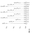
- Figure 4 shows a schematic drawing of multiplexing three-channel subcutaneous signals in synchronization with the sampling clock.
- the device At the time slot k, the device generates one sample digital output U AB (n) representing the differential voltage in lead AB measured at the time slot k, where n is the sample index.
- the device At the next time slot k+1, the device generates one sample digital output U BC (n) representing the differential voltage in lead BC measured at the time slot k+1, where the sample index n remains unchanged.
- the device generates one sample digital output U CA (n) representing the differential voltage in lead CA measured at the time slot k+2, where the sample index n is still unchanged.
- the device generates one sample digital output U AB (n+1) representing the differential voltage in lead AB measured at the time slot k+4, where the sample index is increased to n+1.
- the device sequentially generates the sample output U BC (n+1), U CA (n+1), U AB (n+2), U BC (n+2), U CA (n+2), U AB (n+3), U BC (n+3), U CA (n+3) in the following time slots, and the process repeats.
- U BC sample digital output
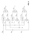
- Figure 5 shows a block diagram of generating three conditional product signals (P AB , P BC , P CA ) from three multiplexed differential voltage signals (U AB , U BC , U CA ).
- U AB , U BC , and U CA are time-multiplexed, for each specific sample index n, U AB (n), U BC (n), and U CA (n) are sampled at three adjacent, rather than the same, time slots. Therefore, -(U BC (n)+U CA (n)) is only an approximate of U AB (n), U AB (n)+U CA (n) is only an approximate of U BC (n), and -(U AB (n)+U BC (n)) is only an approximate of U CA (n).
- the differential voltage signals U BC and U CA are summed and then inversed to generate the signal ⁇ AB , which is a first estimate of the signal U AB .
- U AB and U CA are summed and then inversed to generate the signal ⁇ BC , which is a first estimate of the signal U BC .
- U AB and U BC are summed and then inversed to generate the signal ⁇ CA , which provides a first estimate of the signal U CA .
- the signals U AB and ⁇ AB are processed through a conditional product (CP) unit to generate the composite signal P AB .
- U BC and ⁇ BC are processed through a second CP unit to generate the composite signal P BC
- U CA and ⁇ CA are processed through a third CP unit to generate the composite signal P CA .
- the signals U AB are further processed through a moving average filter to generate the signal U AB , which is a second estimate of the signal U AB .
- U BC is further processed through a moving average filter to generate the signal ⁇ U BC , which is a second estimate of the signal U BC
- U CA is further processed through a moving average filter to generate the signal U CA , which is a second estimate of the signal U CA .
- the conditional product signal P AB is then obtained from ⁇ AB and U AB , which are two different estimates of U AB .
- the conditional product signal P BC is obtained from ⁇ BC and U Bc , which are two different estimates of U BC
- the conditional product signal P CA is obtained from ⁇ CA and U CA , which are two different estimates of U CA .
- U BC (n) is sampled at the time slot k+1, and U CA (n) is sampled at the time slot k+2.
- Their combination -(U BC (n)+U CA (n)) yields a first estimate of U AB had it been sampled between the time slots k+1 and k+2.
- the average of U AB (n) and U AB (n+1) provides a second estimate of U AB had it been sampled between the same time slots k+1 and k+2.
- U AB (n+1) is sampled at the time slot k+3, and U BC (n+1) is sampled at the time slot k+4.
- U BC (n+1) can be estimated as the average of its two neighboring samples, i.e., (U BC (n)+U BC (n+2))/2, or the weighted average of three adjacent samples, i.e., (U BC (n)+2U BC (n+1)+U Bc (n+2))/4, etc.
- FIG. 6 shows a flowchart diagram of implementing the conditional product function.
- the CP unit continuously process two input signals, ⁇ and U , to generate the output signal P.
- the sign of U (n) or U(n) is recorded for later phase correction as described herein below.
- the P(n) is the CP output corresponding to the sample index n.
- Normal subcutaneous ECG signal generally has distinctive signal components such as P wave, QRS complex, and T wave. With sufficiently high sampling frequency, each of these signal components can be represented by multiple samples in the digitized signal. For example, a QRS complex with 100 ms duration can be represented by 25-26 samples at the sampling frequency 256 Hz. Consequently, the morphology of the signal component is rarely affected by the input multiplexing.
- the QRS complex morphology in channel U AB is almost the same no matter the signal is sampled at the time slots k, k+3, k+6, k+9, etc, or sampled at the time slots k+1, k+4, k+7, k+10, etc, or sampled at the time slots k+2, k+5, k+8, k+11, etc.
- noises such as myopotentials, EMI, and many other electrical activities originating from outside the heart
- noise components are usually added to the subcutaneous ECG and shown as random impulses with relatively short durations.
- these noise components are more sensitive to input multiplexing. For example, assume the sampling frequency is 256 Hz, if a noise impulse has ⁇ 4 ms duration, then it is very likely that the noise impulse is sampled at one channel at certain time slot, but not sampled at other two channels due to multiplexing.
- a noise impulse with ⁇ 8 ms duration may be sampled by two channels at two adjacent time slots, but not detected in the third channel.
- the noise component sampled in one channel may have very different morphology than the one estimated from the other two channels, because the noise amplitude may vary significantly from one time slot to the next time slot.
- the CP unit can augment the signal component while suppressing the noise component.
- the signal component sample amplitude of QRS waveform
- the signal component sample amplitude of QRS waveform
- the signal component is likely present in both its first estimate ⁇ (n) and its second estimate U (n)
- these two estimates likely have similar sample amplitude with the same sign.
- the subcutaneous ECG in channel U is contaminated by noise at the sample index n.
- noise component is not consistently present in both ⁇ (n) and U (n).
- noise component may be absent in ⁇ (n) and/or U (n), or has reduced amplitude in U(n) and/or U(n). Even if noise component is present in both U(n) and U(n), it is likely that U(n) and U(n) have very different amplitude and possibly have different signs. If ⁇ (n) and U(n) have different signs, then their conditional product P(n) is set to zero. If ⁇ (n) and U(n) have very different amplitude, then P(n) may also be attenuated, e.g., when either U(n) or U(n) is close to zero.
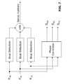
- Fig. 7 shows a block diagram of generating three channels of phase-corrected conditional product signals (S AB , S BC , and S CA ) and the final sense markers by analyzing three input conditional product signals. Because the conditional product signals P AB , P BC , and P CA are always positive, it is desirable to restore the phase information (positive and negative deflections) embedded in the original signals U AB , U BC , and U CA , for example, to facilitate morphological analysis of the subcutaneous ECG. This is achieved by feeding the conditional product signals P AB , P BC , and P CA to a phase correction unit, which generates respective phase-corrected signals S AB , S BC , and S CA .
- a phase correction unit which generates respective phase-corrected signals S AB , S BC , and S CA .
- the phase-correction unit retrieves the previously stored sign values of U AB (n) or ⁇ AB (n) (see Figure 6 ), and applies the signs to the respective input samples P AB (n) to generate output samples S AB (n).
- the output samples S BC (n) and S CA (n) can be similarly obtained.
- the phase-corrected conditional product signals (S AB , S BC , and S CA ) are obtained by applying previously stored sign values to the square root of the respective conditional product signals P AB , P BC , and P CA so that the output signals have the voltage unit.
- the phase-corrected conditional product signal sample S AB (n) is obtained by averaging the first estimate ⁇ AB (n) and the second estimate U AB (n) but with the exception that S AB (n) is set to zero if ⁇ AB (n) and U AB (n) have opposite signs.
- the conditional product signals P AB , P BC , and P CA have much higher signal-to-noise ratio (SNR) than their counterparts U AB , U BC , and U CA .
- the beat detection algorithm is respectively applied to three conditional product signals P AB , P BC , and P CA .
- One exemplary beat detection algorithm is the Auto-Sensing algorithm, which has been disclosed in U.S. Pat. No. 5,891,048 , assigned to the present assignee.
- the Auto-Sensing algorithm applies a detection hold-off period after each peak detection, then automatically adjusts the sensing threshold, which is adaptive to the measured peak amplitude of the QRS complex and varies based on a predetermined time dependence. Therefore, for each conditional product signal, the beat detection algorithm generates a series of sense markers for that specific channel. According to a preferred embodiment, the resulting three series of sense markers are provided to a vote unit for generating the final sense marker output. Specifically, if a QRS complex is detected in 2 out of 3 conditional product signals within a predefined time window (i.e. tolerance of difference in detection time), e.g. 50 ms, then a sense marker is generated for the final beat detection output.
- a predefined time window i.e. tolerance of difference in detection time
- Other more advanced methods to generate the final beat detection output based on 3 channels of sense markers can also be implemented, for example, by assigning different voting weights to different sense marker channels based on assessment of the signal to noise ratio of P AB , P BC , and P CA , where the signal power can be estimated from the conditional product amplitude at or around the sense marker (i.e. within the QRS complex), and the noise power can be estimated from the conditional product amplitude at or around the middle between adjacent sense markers (i.e. within the T-P segment).
- Figure 8 shows an example of three channels of time-multiplexed digital subcutaneous ECG signals U AB , U Bc and U CA .
- the signals are contaminated by high frequency noise.
- the noise power is only slightly lower than the signal power, such that it is difficult to differentiate some true QRS complexes from noise deflections (see for example the marked dashed circles).
- Figure 9 shows the composite signals ⁇ AB , ⁇ BC , ⁇ CA that are estimated from the time-multiplexed differential signals U AB , U BC and U CA .
- the estimated signals ⁇ AB , ⁇ BC , ⁇ CA bear some similarity to the respective signals U AB , U BC and U CA , their morphological differences are also evident.
- the estimated signals are contaminated by high frequency noise. The noise power is only slightly lower than the signal power, such that it is difficult to differentiate some true QRS complexes from noise deflections (see for example the marked dashed circles).
- Figure 10 shows the conditional product signals P AB , P BC , and P CA that are respectively constructed from the first estimated signals ⁇ AB , ⁇ BC , ⁇ CA , and the second estimated signals U AB , U BC and U CA .
- the final sense markers as determined by the method described above are also shown.
- the signal components QRS complexes
- the noise components are substantially reduced.
- the spurious deflections observed in Figure 7 and Figure 8 are either confirmed or rejected as QRS complexes.
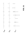
- Figure 11 shows the phase-corrected conditional product signals S AB , S BC , and S CA .
- S AB , S BC , and S CA show the phase-corrected conditional product signals S AB , S BC , and S CA .
- the phase-corrected signals S AB , S BC , and S CA also preserve the phase information of the QRS complexes, thus making them more suitable for ECG interpretation and morphological analysis.
Landscapes
- Health & Medical Sciences (AREA)
- Life Sciences & Earth Sciences (AREA)
- Cardiology (AREA)
- Heart & Thoracic Surgery (AREA)
- Molecular Biology (AREA)
- Pathology (AREA)
- Engineering & Computer Science (AREA)
- Biomedical Technology (AREA)
- Physics & Mathematics (AREA)
- Medical Informatics (AREA)
- Biophysics (AREA)
- Surgery (AREA)
- Animal Behavior & Ethology (AREA)
- General Health & Medical Sciences (AREA)
- Public Health (AREA)
- Veterinary Medicine (AREA)
- Measurement And Recording Of Electrical Phenomena And Electrical Characteristics Of The Living Body (AREA)
Abstract
Description
- The present invention generally relates to medical devices that measure cardiac electrical signals, analyze the said cardiac electrical signals, and detect the cardiac beat for each cardiac cycle. More particularly, the present invention relates to a method and apparatus for robust cardiac beat detection from surface ECG or subcutaneous ECG signals by improving the signal to noise ratio of ECG signals or subcutaneous ECG signals.
- The standard 12-lead electrocardiogram (ECG) is a representation of the heart's electrical activity recorded from electrodes on the body surface. Since its invention by Willem Einthoven in 1904, ECG has been a standard diagnosis tool for evaluating cardiac function. Normal ECG tracing is comprised of different waves that represent the sequence of depolarization and repolarization of the atria and ventricles. For example, the P wave represents atrial depolarization, the QRS complex represents ventricular depolarization, and the T wave represents ventricular repolarization. From these ECG waves, a plural of intervals can be calculated that reflect the cardiac conduction properties (e.g., P wave duration, PR interval, QRS duration), repolarization properties (e.g, QT interval), intrinsic heart rate (e.g., PP or RR intervals), etc. Collectively, these ECG waves and durations contain important diagnostic information regarding the underlying cardiac condition.
- However, many patients have intermittent spontaneous cardiac arrhythmias (e.g., sinus bradycardia, non-sustained ventricular tachycardia, paroxysmal atrial fibrillation, etc.) which may not be recorded during their clinic visits. In order to capture these infrequent arrhythmia episodes, external ECG monitoring devices such as Holters are frequently prescribed to continuously monitor the patient's ECG. However, Holter recording has two inherent drawbacks. First, the memory capacity is limited, and most commercially available Holter machines can only record 24-hr or 48-hr surface ECG. Second, the use of skin electrodes is inconvenient and uncomfortable to patient, and is a significant source of measurement noise due to loose contact, muscle movement, and environmental factors. Consequently, the diagnostic yield of Holter ECG is very limited.
- To overcome these shortcomings, subcutaneous ECG monitors have been introduced. By implanting a small device with sensing electrodes underneath the skin, the subcutaneous ECG monitor can record subcutaneous ECG which resembles the surface ECG. The subcutaneous ECG monitor can be configured as a loop recorder, so that it continuously records newly acquired subcutaneous ECG while discarding the old recordings. When patient experiences symptoms, he/she can use a handheld device which communicates with the subcutaneous device to trigger a snapshot of the recordings. Alternatively, the implantable device can be programmed to automatically trigger a snapshot of the subcutaneous ECG upon detection of an arrhythmic episode. The recorded snapshots can then be transmitted over the telephone or wireless network to the physician's office for clinical review. Because the loop recorder continuously refresh its memory, it can be carried for long periods, thus is ideal for capturing ECG traces of infrequent episodes such as syncope. Recently, subcutaneous ECG recording has also become a useful means to monitor the cardiac rhythm after ablation of atrial fibrillation, to determine the ablation efficacy and adjust therapeutic schemes.
- Irrespective ECG recording apparatus (e.g., ECG machines, bedside ECG monitors, Holter ECG monitors, subcutaneous ECG devices, etc.), reliable beat detection is the prerequisite for further ECG processing and clinical diagnosis. Despite decades of research, ECG beat detection has remained as a technical challenge. On one hand, many factors can cause over-sensing (false detection) of cardiac beats, such as large T waves, wider QRS complexes, muscle noise, electromagnetic interference (EMI), and so on. On the other hand, under-sensing (missed detection) of cardiac beats are also common for ECG signals with small signal to noise ratio. Existing methods for real-time ECG beat detection are either computationally complex that are not suitable for implementation in embedded system, or oversimplified (e.g., rely solely on ECG metrics such as peak amplitude, peak slope, etc., with or without adaptive sensing threshold) that result in unsatisfactory performance.
- In view of above, there is a need to provide a method and apparatus for more accurate and efficient detection of cardiac beats based on surface ECG or subcutaneous ECG recordings.
- The present invention provides a novel method and apparatus for improving the signal to noise ratio of surface ECG or subcutaneous ECG for robust beat detection.
- According to a typical embodiment of the present invention, at least three electrodes are connected to a multiplex input that measures surface ECG or subcutaneous ECG in three sensing leads (AB, BC, CA) that form a triangle. The signals measured from two such leads (BC, CA) are combined to calculate their differential signal, which is a first estimate of the signal measured in the 3rd lead. Preferably, the signal acquired by the 3rd lead (AB) is also processed through a moving average filter to produce a second estimate of signal recorded in the same lead. A conditional product signal (PAB) is then obtained by generating the point-by-point product of the differential signal (the first estimate of the signal) and the averaged signal (the second estimate of the signal) if their sample pair have the same polarity, or setting to zero if the sample pair have different polarity. Similarly, conditional product signals (P BC and P CA) are respectively obtained. These conditional product signals significantly enhance the signal components while reduce the noise components, thus improving the signal to noise ratio of the respective input channels. The conditional product signals (P AB, P BC, P CA) are then respectively subject to peak detection through conventional Auto-Sensing (involve both signal blanking and adaptive thresholding) approach. The preliminary event detection results from all 3 conditional product signals are then aggregated, and the final sense markers for ECG beat detection are generated by means of a voting algorithm.
- The details of the invention can be understood from the following drawings and the corresponding text descriptions.
- Fig. 1
- shows a block diagram of an implantable subcutaneous ECG monitoring device, and its interfaces with an external programming device and an external portable device, which further communicates with the remote service center.
- Fig. 2
- shows a schematic drawing of three spatially distributed electrodes that are capable to measure ECG or subcutaneous signals from three sensing vectors.
- Fig. 3
- shows a simplified block diagram of the front-end of the implantable device that includes a multiplexer and a plural of signal pre-processing units.
- Fig. 4
- shows a schematic drawing of multiplexing three-channel subcutaneous signals in synchronization with the sampling clock.
- Fig. 5
- shows a block diagram of generating three conditional product signals from three multiplexed differential voltage signals.
- Fig. 6
- shows a flowchart diagram of implementing the conditional product function.
- Fig. 7
- shows a block diagram of generating three channels of phase-corrected conditional product signals and the final sense markers by analyzing three input conditional product signals.
- Fig. 8
- shows an example of three channels of time-multiplexed digital subcutaneous ECG signals UAB, UBC and UCA.
- Fig. 9
- shows the composite signals ŨAB, ŨBC, ŨCA that are estimated from the time-multiplexed differential signals UAB, UBC and UCA.
- Fig. 10
- shows the conditional product signals PAB, PBC, and PCA that are respectively constructed from the first estimated signals ŨAB, ŨBC, ŨCA, and the second estimated signals
U AB,U BC ANDU CA. - Fig. 11
- shows the phase-corrected conditional product signals SAB, SBC, and SCA.
-
Figure 1 shows a block diagram of an implantable device for subcutaneous ECG monitoring, and its interfaces with an external programmer and an external portable device, which further communicates with the remote service center. - Refer to
Figure 1 . The implantable device consists of an electronic circuitry that is hermetically sealed inside a Can, which is made from a biocompatible conductive material such as titanium, an optional non-conductive header attached to the Can, three or more sensing electrodes, with or without leads connected to the header. - The sensing electrodes, which are electrically isolated from one another, are mounted over the outer surface of the Can, or outside the header (if available), or at the distal end of the leads (if available). For subcutaneous ECG recording, one or more pairs of sensing electrodes form the sensing vectors and the inter-electrode distance is preferably greater than 3cm.
- The leads are optional for subcutaneous ECG recording. Generally, if the measured subcutaneous ECG amplitude is too small for reliable sensing, despite configuring different sensing vectors and recording at different anatomical locations, then one or more subcutaneous leads (with distal electrodes) could be tunneled under the patient's skin and connected to the header, so that larger subcutaneous ECG amplitude could be measured by increasing inter-electrode distance, e.g., between the lead electrode and the Can or header electrode.
- Still refer to
Figure 1 . Enclosed inside the hermetically sealed Can, a microprocessor and associated circuitry make up the controller of the implant device. The implant device is powered by a battery, and maintains an internal clock for timing the operations. The microprocessor communicates with a memory via a bi-directional data bus. The memory typically comprises a ROM or RAM for program storage and a RAM for data storage. - The sensing electrodes are first connected to an electronic interface that preferably includes a feedthrough circuitry for noise reduction, a high voltage protection circuitry, a switch network circuitry for sensing channel selection, and front-end analog filters, as well known in the field. The configurations of the interface circuitry (e.g., filter settings, sensing channel selection, etc.) can be programmed by the microprocessor.
- The microprocessor connects to an I/O control unit to manage the input and output of the implant device. One input signal is the subcutaneous ECG picked up by the sensing electrodes. After pre-processed by the interface circuitry, the subcutaneous ECG signal is further processed by the ECG sensing unit, which usually consists of amplifiers, analog-to-digital converters, digital filters, etc., as known in the art.
- Another input signal is the impedance (Z) signal measured between the sensing electrodes. By injecting a small constant current (e.g., 100uA, preferably biphasic) between two electrodes while measuring the voltage difference between the same or different pair of electrodes, the impedance is calculated as the ratio between the measured voltage difference and the injecting current strength. As known in the art, the impedance signal provides useful information on the integrity of the sensing channel. In addition, the continuously measured impedance signal may be further processed by the microprocessor to extract other physiological status of the patient, such as the respiration rate.
- Other types of biological signals measured by specific sensors can also serve as input to the implant device. For example, an on-board accelerometer can serve as a motion sensor that provides patient's activity signal to the implant device, an on-board (or embedded in the lead) temperature sensor can provide the subcutaneous temperature signal to the implant device. Other types of input signals include, but are not limited to, the subcutaneous pressure signal measured by a pressure sensor, the acoustic signal measured by an acoustic sensor, the subcutaneous pH signal measured by a pH sensor, etc.
- By running the program stored in the memory, the microprocessor also sends instructions to the ECG sensing unit, the impedance measurement unit, and other input measurement units to control how these signals are acquired (e.g., gain, offset, filter settings, sampling frequency, sampling resolution, etc.).
- The acquired biological signals are then stored in the device memory and analyzed by the microprocessor by running programmed algorithms. For example, the microprocessor continuously analyze the acquired subcutaneous ECG signals to detect the peak of QRS complex. Such QRS peak detection can be achieved by many different means. One typical embodiment is to use an Auto-Sensing algorithm that applies a detection hold-off period after each peak detection, then automatically adjusts the sensing threshold, which is adaptive to the measured peak amplitude of the QRS complex and varies based on a predetermined time dependence. One exemplary Auto-Sensing algorithm has been disclosed in
U.S. Pat. No. 5,891,048 , assigned to the present assignee. In this invention, a more robust ECG beat detection method is described in details below. - Accordingly, the implant device measures the intervals between any two adjacent peaks of the detected QRS complexes, and these intervals are termed RR intervals. These measured RR intervals are stored in the device memory according to predefined storage modes. One typical mode is the queue-loop mode, meaning the measured RR intervals are stored in a predefined memory space, and while the allocated memory space is full, the newly measured RR intervals replace the oldest stored RR interval data. Another typical mode is the snapshot mode, meaning the measured RR intervals are stored in a predefined memory space, and while the allocated memory space is full, the newly measured RR intervals are not stored until the microprocessor decides to store another episode of RR intervals. Yet another typical mode is the mixed mode, in which one or more segments of allocated memory space store the RR intervals in queue-loop mode, whereas one or more segments of separately allocated memory space store the RR intervals in snapshot mode.
- Similarly, the microprocessor can also continuously analyze the acquired subcutaneous ECG signals to measure other metrics of the QRS complex, such as the width of the QRS complex, the positive or negative peak amplitude of the QRS complex, the absolute area under the QRS complex, the maximum positive or negative slopes of the QRS complex, the dominant frequency component of the QRS complex, the complexity measures (e.g., sampled entropy) of the QRS complex, and so on. Likewise, the time series of these measured metrics are stored in the device memory for further analysis.
- The implant device also includes a radio-frequency (RF) telemetry unit. The RF telemetry unit may be of the type well known in the art for conveying various information which it obtains from the implant device to the external programmer, or for receiving programming parameters from the external programmer and then conveys to the implant device. In one typical embodiment, the external programmer can interrogate the implant device to get the status of the implant device (e.g., battery status, sensing channel impedance, etc.) or the data recorded by the implant device (e.g., peak amplitude of the QRS complexes, statistics of measured RR intervals, etc.). In another typical embodiment, the external programmer can be used to activate or deactivate selected algorithms or update programmable parameters of the implant device.
- In addition, the external portable device to be described hereinafter, can also communicate bi-directionally with the implant device through the telemetry unit. Preferably, the data that may be received from or sent to the external portable device are more limited as compared to the data that may be received from or sent to the external programmer.
- In a preferred embodiment, the data that are transmitted from the external portable device to the implant device are simple commands, such as trigger a snapshot of the acquired subcutaneous ECG, retrieve most recently diagnostic information from the implanted device, etc. These commands set the implant device into one of a number of modalities wherein each modality is determined and controlled by parameters that can only be selected by a physician operating the external programmer using secure password or codes.
- The data that are transmitted from the implant device to the external portable device preferably include simple acknowledgment to confirm receiving the commands from the external portable device, the signals warning the detection of abnormal conditions, such as detection of atrial fibrillation (AF), detection of high ventricular rate (HVR), detection of low ventricular rate (LVR), detection of abnormal sensing impedance, detection of abnormal temperature, and so on. Other diagnostic information, such as the AF burden, the frequency of ectopic beats, snapshots of RR intervals or subcutaneous ECG, etc., can also be transmitted to the external portable device. Preferably, a physician operating the external programmer using secure password or codes controls the enable or disable condition as well as the amount of data that can be transmitted from the implant device to the external portable device.
- Still refer to
Figure 1 . The external portable device has a power source, such as a lithium battery, which provides power to the electrical components of the device. The battery is chargeable by connecting to an external charger. The external portable device also maintains an internal clock for timing its operations. The overall functioning of the external portable device is controlled by its microprocessor, which reads and performs instructions stored in its associated memory. The instructions stored in memory preferably include instructions defining a communication protocol compatible with the implant device, and instructions defining a communication protocol compatible with the remote service center. - The microprocessor of the external portal device communicates with an I/O control unit to read from the keypad (or press switches) the patient input commands. In an exemplary embodiment, one subset of the input commands is designed to configure the external portable device, for example, to turn on or off certain outputs as described hereinafter, or select specific communication protocols. Another subset of the input commands is designed to establish communication between the external portable device and the remote service center through remote communication unit. For example, patient's input can command the external portable device to transmit diagnostic information (retrieved from the implant device) to the remote service center, and wait to receive acknowledgement. The third subset of the commands is designed to establish communication between the external portable device and the implant device through implant communication unit. For example, patient's input can command the external portable device to transmit corresponding signals to the implant device to trigger recording a snapshot of the subcutaneous ECG, to retrieve diagnostic information from the implanted device, etc. The implant communication unit also receives the acknowledgement and related diagnostic information sent from the implant device, and conveys these data to the microprocessor for storage in the memory.
- According to one exemplary embodiment of the present invention, upon receiving a predefined warning signal from the implant device (e.g., detection of AF, detection of HVR, detection of LVR, detection of abnormal sensing impedance, detection of abnormal temperature, etc.), the microprocessor of the external portable device communicates with the I/O control unit to generate output that is perceptible by the patient. Such output can be in the form of visible message, such as the light-up or blinking of a light emitting diode (LED) or the text message displayed in a liquid crystal display (LCD), or in the form of audible message such as beep, ringing tone, or pre-recorded voice messages played by a speaker, or in the form of discernible vibration by a vibrator. According to the patient's preference, one or multiple types of warning message can be respectively turned on or off. For example, the visible warning message can be turned on while the audible warning message can be turned off during the night if the patient chooses not to be disturbed during sleep even if the implant device detects AF. Besides generating warning messages, some diagnostic information that is received from the implant device and stored in memory (e.g., the heart rate) can also be provided to the patient in the form of visual or audible messages.
- The external portable device, via its remote communication unit, can further communicate with the remote service center. Such long-range communication apparatus can be in the form of a mobile radio network, or a fixed-line telecommunication network, or the internet, as well known in the art. Examples of such long-range communication apparatus have been taught in
U.S. Pat. No. 6,470,215 ,U.S. Pat. No. 6,574,509 ,U.S. Pat. No. 6,622,043 , all are assigned to the assignee of the present invention and incorporated herein by reference. - In one typical embodiment, the external portable device transmits the implant device status information (e.g., battery status, sensing impedance, etc.) as well as relevant diagnostic information (e.g., AF burden, ectopic beat frequency, etc.) to the remote service center according to a predefined transmission frequency and schedule (e.g., every midnight, etc.). Yet in another typical embodiment, the external portable device communicates with the remote service center in a trigger mode, for example, upon receiving a warning signal from the implant device, or upon the patient trigger. In such cases, the external portable device transmits critical diagnostic information stored in device memory (e.g., AF burden, mean heart rate, the subcutaneous ECG snapshot, etc.) to the remote service center.
- The remote service center receives the information via compatible communication protocols, then sends acknowledgement back to the external portable device, which may generate visible or audible output indicating receipt of the acknowledgement. The data received by the remote service center is stored in a central database, and is promptly presented to the patient's physician or responsible expert through proper means, such as fax, email, and text message as known in the art. By reviewing the received diagnostic information, the physician can evaluate the patient's condition and provide expert advice to the patient who wishes to contact the physician before taking any action in response to the warning signals generated by the external portable device.
- The method and apparatus for cardiac beat detection from subcutaneous ECG recordings is disclosed hereinafter. It shall be understood that the same principles are also applicable to cardiac beat detection from surface ECG recorded using conventional ECG machines, bedside ECG monitors, Holter ECG devices, automatic external defibrillators, etc.
- According to a preferred embodiment of this invention, at least three sensing electrodes are connected to the input channels of the implantable device to measure the subcutaneous ECG. The three sensing electrodes are implanted underneath the chest skin and are spatially separated, preferably with inter-electrode distance >3 cm for each pair. As illustrated in
Figure 2 , three sensing electrodes (labeled as A, B, and C) respectively measure the focal subcutaneous electric potentials ΦA, ΦB, and ΦC. These three sensing electrodes form three sensing vectors or leads that form a triangle. Specifically, electrodes A and B form lead AB that measures ΦAB, which is the voltage difference between ΦA and ΦB. Similarly, electrodes B and C form lead BC that measures ΦBC, which is the voltage difference between ΦB and ΦC. Likewise, electrodes C and A form lead CA that measures ΦCA, which is the voltage difference between ΦC and ΦA. Hence, the triangular voltage measurement provides at least three channels of subcutaneous ECG signal input to the subcutaneous implantable device. -
Figure 3 shows a simplified block diagram of the front-end of the implantable device that receives the analog voltage signals from three sensing electrodes and generates three channels of multiplexed digital output. In this figure, the front-end circuit consists of 5 signal processing layers: (1) the multiplexer, (2) the differential amplifiers, (3) the analog filters, (4) the analog-to-digital converter (ADC), and (5) the digital filters. - As shown in
Figure 3 , three subcutaneous sensing electrodes (A, B, C) respectively measure the focal subcutaneous electric potentials ΦA, ΦB, and ΦC, and are connected to the input of a multiplexer. The multiplexer is controlled by the microprocessor of the implantable device, which divides the time domain into three recurrent timeslots of fixed length, and then sequentially selects two sensing electrodes at a time to obtain three time-multiplexed differential voltage signals ΦAB, ΦBC, ΦCA. In synchronization with the system clock, the microprocessor selects the pair of sensing electrodes according to the sampling frequency which determines the multiplexing timeslot length. For example, if the sampling frequency is 256 Hz, then the multiplexing timeslot length is about 3.9 ms. - Still refer to
Figure 3 . The multiplexed signals (ΦAB, ΦBC, ΦA) are connected to the differential amplifiers which amplify the differential voltage signals while providing common mode rejection. The amplified differential voltage signals are then connected to the analog filters, which include at least anti-aliasing low pass filters whose cut-off frequency corresponds to the highest frequency component of interest in subcutaneous ECG signals, e.g., 128 Hz. In addition, the analog filters also include high pass filters with sufficiently low corner frequency, e.g., 0.5 Hz, to remove the DC offset component. Preferably, the analog filters also include the 50 Hz or 60 Hz notch filters that remove the power-line interference. - Through the ADC, the amplified and analog-filtered differential voltage signals are then converted to digital signals according to predefined or user-programmable sampling frequency, e.g., 128 Hz, 256 Hz, 512 Hz, etc. The converted digital signals are then further processed through digital filters whose filter characteristics (e.g., filter type, order, gain, corner frequencies, etc.) are user-programmable. By adjusting the digital filter characteristics, user can optimize signal quality for specific applications. For example, for reliable beat detection, T wave can be attenuated to avoid T wave over-sensing.
- Therefore, the front-end of the implantable device converts the analog voltage input from three sensing electrodes (ΦA, ΦB and ΦC) to three channels of time-multiplexed digital subcutaneous ECG signals UAB, UBc and UCA. In a preferred embodiment, the gains and filter settings for all three channels in the front-end are the same.
-
Figure 4 shows a schematic drawing of multiplexing three-channel subcutaneous signals in synchronization with the sampling clock. At the time slot k, the device generates one sample digital output UAB(n) representing the differential voltage in lead AB measured at the time slot k, where n is the sample index. At the next time slot k+1, the device generates one sample digital output UBC(n) representing the differential voltage in lead BC measured at the time slot k+1, where the sample index n remains unchanged. Then at the next time slot k+2, the device generates one sample digital output UCA(n) representing the differential voltage in lead CA measured at the time slot k+2, where the sample index n is still unchanged. Then at the next time slot k+3, the device generates one sample digital output UAB(n+1) representing the differential voltage in lead AB measured at the time slot k+4, where the sample index is increased to n+1. Following the similar steps, the device sequentially generates the sample output UBC(n+1), UCA(n+1), UAB(n+2), UBC(n+2), UCA(n+2), UAB(n+3), UBC(n+3), UCA(n+3) in the following time slots, and the process repeats. As a result, for each specific sample index, there is one digital sample in each of the three output channels. However, these three digital samples represent the differential voltages in respective leads that are measured at three different time slots. -
Figure 5 shows a block diagram of generating three conditional product signals (PAB, PBC, PCA) from three multiplexed differential voltage signals (UAB, UBC, UCA). - At any time instant, the cardiac electrical activity can be represented as a 3D dipolar vector, which is projected onto the 3 sensing channels. Therefore, ΦBC measures the far-field projection of the cardiac vector along the BC axis, ΦCA measures the far-field projection of the cardiac vector along the CA axis, and ΦAB measures the far-field projection of the cardiac vector along the AB axis. According to the principles of vector arithmetic, at any time instant t, ΦAB(t)=-(ΦBC(t)+ΦCA(t)), ΦBC(t)=ΦAB(t)+ΦCA(t), ΦCA(t)=-(ΦAB(t)+ΦBC(t)). Because the gains and filter settings for all three channels in the front-end are the same, the same arithmetic relationship would also hold true for the three digital signals had the data been sampled at the same time, that is, at any time instant t, UAB(t)=-(UBC(t)+UCA(t)), UBC(t)=UAB(t)+UCA(t), UCA(t)=-(UAB(t)+UBC(t)).
- However, because UAB, UBC, and UCA are time-multiplexed, for each specific sample index n, UAB(n), UBC(n), and UCA(n) are sampled at three adjacent, rather than the same, time slots. Therefore, -(UBC(n)+UCA(n)) is only an approximate of UAB(n), UAB(n)+UCA(n) is only an approximate of UBC(n), and -(UAB(n)+UBC(n)) is only an approximate of UCA(n).
- Now refer to
Figure 5 . The differential voltage signals UBC and UCA are summed and then inversed to generate the signal ŨAB, which is a first estimate of the signal UAB. Similarly, UAB and UCA are summed and then inversed to generate the signal ŨBC, which is a first estimate of the signal UBC. Likewise, UAB and UBC are summed and then inversed to generate the signal ŨCA, which provides a first estimate of the signal UCA. - According to one embodiment of the invention, the signals UAB and ŨAB are processed through a conditional product (CP) unit to generate the composite signal PAB. Similarly, UBC and ŨBC are processed through a second CP unit to generate the composite signal PBC, and UCA and ŨCA are processed through a third CP unit to generate the composite signal P CA.
- According to another embodiment of the invention, the signals UAB are further processed through a moving average filter to generate the signal
U AB, which is a second estimate of the signal UAB. Similarly, UBC is further processed through a moving average filter to generate the signal̅U BC, which is a second estimate of the signal UBC, and UCA is further processed through a moving average filter to generate the signalU CA, which is a second estimate of the signal UCA. As shown inFigure 5 , the conditional product signal P AB is then obtained from ŨAB andU AB, which are two different estimates of UAB. Likewise, the conditional product signal PBC is obtained from ŨBC andU Bc, which are two different estimates of UBC, and the conditional product signal PCA is obtained from ŨCA andU CA, which are two different estimates of UCA. - The benefit of using moving average filters is to better align the second estimated signals to the first estimated signals. Refer back to
Figure 4 . UBC(n) is sampled at the time slot k+1, and UCA(n) is sampled at the time slot k+2. Their combination -(UBC(n)+UCA(n)) yields a first estimate of UAB had it been sampled between the time slots k+1 and k+2. Meanwhile, the average of UAB(n) and UAB(n+1) provides a second estimate of UAB had it been sampled between the same time slots k+1 and k+2. Similarly, UAB(n+1) is sampled at the time slot k+3, and UBC(n+1) is sampled at the time slot k+4. Their combination - (UAB(n+1)+UBC(n+1)) yields a first estimate of UCA had it been sampled between the time slots k+3 and k+4. Meanwhile, the average of UCA(n) and UCA(n+1) provides a second estimate of UCA had it been sampled between the same time slots k+3 and k+4. On the other hand, note that UAB(n+1) is sampled at the time slot k+3, and UCA(n+1) is sampled at the time slot k+5. Their combination UAB(n+1)+UCA(n+1) yields a first estimate of UBC sample at the time slots k+4, which is exactly UBC(n+1). In this case, it is not necessary to apply moving average to obtain a second estimate of UBC because UBC is already aligned with UAB+UCA. Alternatively, we can still apply a moving average filter to generate a second estimate of UBC without changing its alignment with UAB+UCA. For example, UBC(n+1) can be estimated as the average of its two neighboring samples, i.e., (UBC(n)+UBC(n+2))/2, or the weighted average of three adjacent samples, i.e., (UBC(n)+2UBC(n+1)+UBc(n+2))/4, etc. - Now refer to
Figure 6 , which shows a flowchart diagram of implementing the conditional product function. The CP unit continuously process two input signals, Ũ andU , to generate the output signal P. For each sample index n, the CP unit gets the pair of input samples U(n) and U(n). If the sample pair have opposite signs, i.e., if Ũ(n)>0 andU (n)<0, or Ũ(n)<0 andU (n>0, then P(n) is set to 0. Otherwise, P(n) is set to their product, i.e., P(n)=Ũ(n)*U̅ (n). In addition, the sign ofU (n) or U(n) is recorded for later phase correction as described herein below. The P(n) is the CP output corresponding to the sample index n. Although not shown in this figure, an alternative method is to set P(n)=0 if Ũ(n) andU (n) have opposite signs, and set P(n)=Ũ(n)+U (n) or P(n)=[Ũ(n)+U̅ (n)]/2 if Ũ(n) andU (n) have the same sign. - Normal subcutaneous ECG signal generally has distinctive signal components such as P wave, QRS complex, and T wave. With sufficiently high sampling frequency, each of these signal components can be represented by multiple samples in the digitized signal. For example, a QRS complex with 100 ms duration can be represented by 25-26 samples at the sampling frequency 256 Hz. Consequently, the morphology of the signal component is rarely affected by the input multiplexing. For example, the QRS complex morphology in channel UAB is almost the same no matter the signal is sampled at the time slots k, k+3, k+6, k+9, etc, or sampled at the time slots k+1, k+4, k+7, k+10, etc, or sampled at the time slots k+2, k+5, k+8, k+11, etc.
- In contrast, many noises such as myopotentials, EMI, and many other electrical activities originating from outside the heart, have much higher frequency components. These noise components are usually added to the subcutaneous ECG and shown as random impulses with relatively short durations. As a result, these noise components are more sensitive to input multiplexing. For example, assume the sampling frequency is 256 Hz, if a noise impulse has <4 ms duration, then it is very likely that the noise impulse is sampled at one channel at certain time slot, but not sampled at other two channels due to multiplexing. Similarly, at the sampling frequency 256 Hz, a noise impulse with <8 ms duration may be sampled by two channels at two adjacent time slots, but not detected in the third channel. Even if the noise duration is longer and the noise component is sampled in all three channels, the noise component sampled in one channel may have very different morphology than the one estimated from the other two channels, because the noise amplitude may vary significantly from one time slot to the next time slot.
- Still refer to
Figure 6 . Because the signal component is not sensitive to multiplexing whereas the noise component is more sensitive to multiplexing, the CP unit can augment the signal component while suppressing the noise component. For example, assume the subcutaneous ECG in channel U shows a QRS complex at the sample index n. Then the signal component (sample amplitude of QRS waveform) is likely present in both its first estimate Ũ(n) and its second estimateU (n), and these two estimates likely have similar sample amplitude with the same sign. Thus, their product P(n)=Ũ(n)*U (n) is positive, and augments more for larger sample amplitude (e.g., QRS peak). In contrast, assume the subcutaneous ECG in channel U is contaminated by noise at the sample index n. Then it is very likely that the noise component is not consistently present in both Ũ(n) andU (n). For example, noise component may be absent in Ũ(n) and/orU (n), or has reduced amplitude in U(n) and/or U(n). Even if noise component is present in both U(n) and U(n), it is likely that U(n) and U(n) have very different amplitude and possibly have different signs. If Ũ(n) and U(n) have different signs, then their conditional product P(n) is set to zero. If Ũ(n) and U(n) have very different amplitude, then P(n) may also be attenuated, e.g., when either U(n) or U(n) is close to zero. -
Fig. 7 shows a block diagram of generating three channels of phase-corrected conditional product signals (SAB, SBC, and SCA) and the final sense markers by analyzing three input conditional product signals. Because the conditional product signals PAB, PBC, and PCA are always positive, it is desirable to restore the phase information (positive and negative deflections) embedded in the original signals UAB, UBC, and UCA, for example, to facilitate morphological analysis of the subcutaneous ECG. This is achieved by feeding the conditional product signals PAB, PBC, and PCA to a phase correction unit, which generates respective phase-corrected signals SAB, SBC, and SCA. According to a preferred embodiment, the phase-correction unit retrieves the previously stored sign values ofU AB(n) or ŨAB(n) (seeFigure 6 ), and applies the signs to the respective input samples PAB(n) to generate output samples SAB(n). The output samples SBC(n) and SCA(n) can be similarly obtained. According to another embodiment, the phase-corrected conditional product signals (SAB, SBC, and SCA) are obtained by applying previously stored sign values to the square root of the respective conditional product signals PAB, PBC, and PCA so that the output signals have the voltage unit. Yet according to another embodiment (not shown in the figure), the phase-corrected conditional product signal sample SAB(n) is obtained by averaging the first estimate ŨAB(n) and the second estimateU AB(n) but with the exception that SAB(n) is set to zero if ŨAB(n) andU AB(n) have opposite signs. - Still refer to
Figure 7 . As described above, by amplifying the signal component while suppressing the noise component, the conditional product signals PAB, PBC, and PCA have much higher signal-to-noise ratio (SNR) than their counterparts UAB, UBC, and UCA. According to this invention, the beat detection algorithm is respectively applied to three conditional product signals PAB, PBC, and PCA. One exemplary beat detection algorithm is the Auto-Sensing algorithm, which has been disclosed inU.S. Pat. No. 5,891,048 , assigned to the present assignee. In brief, the Auto-Sensing algorithm applies a detection hold-off period after each peak detection, then automatically adjusts the sensing threshold, which is adaptive to the measured peak amplitude of the QRS complex and varies based on a predetermined time dependence. Therefore, for each conditional product signal, the beat detection algorithm generates a series of sense markers for that specific channel. According to a preferred embodiment, the resulting three series of sense markers are provided to a vote unit for generating the final sense marker output. Specifically, if a QRS complex is detected in 2 out of 3 conditional product signals within a predefined time window (i.e. tolerance of difference in detection time), e.g. 50 ms, then a sense marker is generated for the final beat detection output. Otherwise (e.g., only one of the three conditional product signals has a beat detection), then no sense marker is generated for the final beat detection output. According to another embodiment of the invention, if and only if a QRS complex is detected in all 3 conditional product signals within a predefined time window (i.e. tolerance of difference in detection time), e.g. 50 ms, then a sense marker is generated for the final beat detection output. Yet according to a further embodiment of the invention, if a QRS complex is detected in any one of the 3 conditional product signals, then a sense marker is generated for the final beat detection output. Other more advanced methods to generate the final beat detection output based on 3 channels of sense markers can also be implemented, for example, by assigning different voting weights to different sense marker channels based on assessment of the signal to noise ratio of PAB, PBC, and PCA, where the signal power can be estimated from the conditional product amplitude at or around the sense marker (i.e. within the QRS complex), and the noise power can be estimated from the conditional product amplitude at or around the middle between adjacent sense markers (i.e. within the T-P segment). -
Figure 8 shows an example of three channels of time-multiplexed digital subcutaneous ECG signals UAB, UBc and UCA. Despite the filtering by the front-end circuit, the signals are contaminated by high frequency noise. The noise power is only slightly lower than the signal power, such that it is difficult to differentiate some true QRS complexes from noise deflections (see for example the marked dashed circles). -
Figure 9 shows the composite signals ŨAB, ŨBC, ŨCA that are estimated from the time-multiplexed differential signals UAB, UBC and UCA. Although in general the estimated signals ŨAB, ŨBC, ŨCA bear some similarity to the respective signals UAB, UBC and UCA, their morphological differences are also evident. Still, the estimated signals are contaminated by high frequency noise. The noise power is only slightly lower than the signal power, such that it is difficult to differentiate some true QRS complexes from noise deflections (see for example the marked dashed circles). -
Figure 10 shows the conditional product signals PAB, PBC, and PCA that are respectively constructed from the first estimated signals ŨAB, ŨBC, ŨCA, and the second estimated signalsU AB,U BC andU CA. In addition, the final sense markers as determined by the method described above are also shown. Clearly, for each channel, the signal components (QRS complexes) are significantly enhanced whereas the noise components are substantially reduced. The spurious deflections observed inFigure 7 andFigure 8 are either confirmed or rejected as QRS complexes. - Finally,
Figure 11 shows the phase-corrected conditional product signals SAB, SBC, and SCA. Compared to the original subcutaneous ECG signals UAB, UBC and UCA, dramatic improvement of SNR is achieved for SAB, SBC, and SCA. Furthermore, compared to the conditional product signals P AB, P BC, and P CA, the phase-corrected signals SAB, SBC, and SCA also preserve the phase information of the QRS complexes, thus making them more suitable for ECG interpretation and morphological analysis.
Claims (10)
- A method of enhancing the signal-to-noise ratio (SNR) of measured electrocardiogram (ECG) signals, the method comprising:providing at least three cardiac input signals derived from the measured ECG signals;forming a differential signal from each of at least three pairs of input signals;forming an averaged signal from each of the input signals;characterized in thata conditional product (CP) signal is calculated by generating, from each differential signal and each averaged signal, a product of the differential and averaged signals.
- The method of claim 1, characterized in that forming an averaged signal is accomplished using a moving average filter.
- The method of claim 1, characterized in that the measured ECG signals are of a type obtained from surface measurements.
- The method of claim 1, characterized in that the measured ECG signals are of a type obtained from subcutaneous measurements.
- The method of claim 1, characterized in that the enhanced SNR facilitates cardiac beat detection when the obtained conditional product signals are subject to peak detection in an auto-sensing approach.
- A cardiac device for use in detecting heartbeats, to which at least three sensing electrodes are attached to provide at least three analog voltage input signals, the device comprising:an electrocardiogram (ECG) sensing unit for use in producing digital signals from the analog voltage input signals comprising a multiplexer and a plurality of signal processing units; anda programmable microprocessor coupled to the electrocardiogram (ECG) sensing unit;characterized in thatthe microprocessor calculates differential signals from each of at least three pairs of input signals and calculates an averaged signal from each of the input signals and enhances the SNR of the input signals by generating conditional product signals from the differential signals and the averaged signals.
- The cardiac device of claim 6, characterized in that the signal processing units are selected from the group consisting of differential amplifiers, analog filters, analog-to-digital converters, and digital filters.
- The cardiac device of claim 6 or 7, further comprising on-board biological input sensors.
- The cardiac device of any of claim 6 to 8, further comprising an impedance sensor for use in monitoring integrity of the sensing electrodes.
- The cardiac device of any of claim 6 to 9, characterized in that it is implantable in the chest of a patient, the device further comprising an RF unit for use in communicating signals to external parties.
Applications Claiming Priority (1)
| Application Number | Priority Date | Filing Date | Title |
|---|---|---|---|
| US26485209P | 2009-11-30 | 2009-11-30 |
Publications (2)
| Publication Number | Publication Date |
|---|---|
| EP2327360A1 true EP2327360A1 (en) | 2011-06-01 |
| EP2327360B1 EP2327360B1 (en) | 2012-10-31 |
Family
ID=43662046
Family Applications (1)
| Application Number | Title | Priority Date | Filing Date |
|---|---|---|---|
| EP10192866A Not-in-force EP2327360B1 (en) | 2009-11-30 | 2010-11-29 | Method and apparatus for improving signal to noise ratio of ECG signals to facilitate cardiac beat detection |
Country Status (2)
| Country | Link |
|---|---|
| US (1) | US8396538B2 (en) |
| EP (1) | EP2327360B1 (en) |
Cited By (4)
| Publication number | Priority date | Publication date | Assignee | Title |
|---|---|---|---|---|
| US8092393B1 (en) | 2010-07-28 | 2012-01-10 | Impact Sports Technologies, Inc. | Monitoring device with an accelerometer, method and system |
| US8172761B1 (en) | 2004-09-28 | 2012-05-08 | Impact Sports Technologies, Inc. | Monitoring device with an accelerometer, method and system |
| US8915859B1 (en) | 2004-09-28 | 2014-12-23 | Impact Sports Technologies, Inc. | Monitoring device, system and method for a multi-player interactive game |
| US9380956B2 (en) | 2011-09-28 | 2016-07-05 | Samsung Electronics Co., Ltd. | Method and apparatus for classifying cardiac arrhythmia |
Families Citing this family (12)
| Publication number | Priority date | Publication date | Assignee | Title |
|---|---|---|---|---|
| US9211414B2 (en) | 2011-05-12 | 2015-12-15 | Biotronik Se & Co Kg | Implantable heart stimulator and method for trending analysis of ventricular activation time |
| US8718750B2 (en) | 2011-05-26 | 2014-05-06 | Biotronik Se & Co. Kg | Heart stimulator and method for A-V delay optimization |
| EP2710953B1 (en) | 2012-09-21 | 2015-03-04 | BIOTRONIK SE & Co. KG | Method of enhancing the signal-to-noise ratio (SNR) of measured electrocardiogram (ECG) signals and a cardiac device for use in detecting heartbeats |
| US9636029B1 (en) * | 2013-03-14 | 2017-05-02 | Vital Connect, Inc. | Adaptive selection of digital ECG filter |
| US9558421B2 (en) * | 2013-10-04 | 2017-01-31 | Reald Inc. | Image mastering systems and methods |
| US9993173B2 (en) | 2015-09-30 | 2018-06-12 | Biotronik Se & Co. Kg | Analysis of ECG data for arrhythmia |
| US11013488B2 (en) * | 2017-06-23 | 2021-05-25 | Stryker Corporation | Patient monitoring and treatment systems and methods |
| US11413005B2 (en) | 2017-08-14 | 2022-08-16 | Stryker Corporation | Constitutive equation for non-invasive blood pressure measurement systems and methods |
| US11218142B2 (en) * | 2018-06-25 | 2022-01-04 | Biosense Webster (Israel) Ltd. | Signal quality in a multiplexing system by actively disconnecting unused connections |
| WO2020086112A1 (en) * | 2018-10-24 | 2020-04-30 | Chi-Hua Foundation | Multi-channel real-time cardiovascular performance evaluation system and method |
| US12463652B2 (en) | 2021-09-28 | 2025-11-04 | Texas Instruments Incorporated | Resistor-based digital to analog converter |
| US12345611B2 (en) * | 2022-07-29 | 2025-07-01 | Network Rail Infrastructure Limited | Mutual alignment of rail geometry measurements |
Citations (5)
| Publication number | Priority date | Publication date | Assignee | Title |
|---|---|---|---|---|
| US5891048A (en) | 1996-06-18 | 1999-04-06 | Biotronik Mess- Und Therapiegeraete Gmbh & Co. Ingenieurbuero Berlin | Signal detector |
| US6470215B1 (en) | 1999-06-25 | 2002-10-22 | Biotronik Mess-Und Therapiegeraete Gmbh & Co Ingenieurbuero Berlin | Method of data transmission in implant monitoring |
| US6574509B1 (en) | 1999-06-25 | 2003-06-03 | Biotronik Mass- Und Therapiegerate Gmbh & Co. Ingenieurbuero Berlin | Apparatus for the transmission of data in particular from an electromedical implant |
| US6622043B1 (en) | 1999-06-25 | 2003-09-16 | Biotronik Mess- Und Therapiegeraete Gmbh & Co. Ingenieurbuero Berlin | Method of data interrogation in implant after-care |
| US20090318821A1 (en) * | 2008-06-19 | 2009-12-24 | Nikolaus Demharter | Method for Checking ECG Signals and ECG Measuring Device |
Family Cites Families (2)
| Publication number | Priority date | Publication date | Assignee | Title |
|---|---|---|---|---|
| GB0810843D0 (en) * | 2008-06-13 | 2008-07-23 | Monica Healthcare Ltd | Electrode and electrode positioning arrangement for abdominal fetal electrocardiogram detection |
| TWI424832B (en) * | 2008-12-15 | 2014-02-01 | 波提亞斯數位康健公司 | Body related receiver and method thereof |
-
2010
- 2010-11-24 US US12/954,418 patent/US8396538B2/en not_active Expired - Fee Related
- 2010-11-29 EP EP10192866A patent/EP2327360B1/en not_active Not-in-force
Patent Citations (5)
| Publication number | Priority date | Publication date | Assignee | Title |
|---|---|---|---|---|
| US5891048A (en) | 1996-06-18 | 1999-04-06 | Biotronik Mess- Und Therapiegeraete Gmbh & Co. Ingenieurbuero Berlin | Signal detector |
| US6470215B1 (en) | 1999-06-25 | 2002-10-22 | Biotronik Mess-Und Therapiegeraete Gmbh & Co Ingenieurbuero Berlin | Method of data transmission in implant monitoring |
| US6574509B1 (en) | 1999-06-25 | 2003-06-03 | Biotronik Mass- Und Therapiegerate Gmbh & Co. Ingenieurbuero Berlin | Apparatus for the transmission of data in particular from an electromedical implant |
| US6622043B1 (en) | 1999-06-25 | 2003-09-16 | Biotronik Mess- Und Therapiegeraete Gmbh & Co. Ingenieurbuero Berlin | Method of data interrogation in implant after-care |
| US20090318821A1 (en) * | 2008-06-19 | 2009-12-24 | Nikolaus Demharter | Method for Checking ECG Signals and ECG Measuring Device |
Non-Patent Citations (3)
| Title |
|---|
| ANONYMOUS: "Electrocardiography I Laboratory", 2006, pages 1 - 17, XP002628270, Retrieved from the Internet <URL:http://biomed.engr.sc.edu/bme_lab/lab%20reports/36%29%20ECG%20I.pdf> [retrieved on 20110315] * |
| KLIGFIELD ET AL: "Recommendations for the standardization and interpretation of the electrocardiogram", HEART RHYTHM, vol. 4, no. 3, 7 March 2007 (2007-03-07), pages 394 - 412, XP005915945, ISSN: 1547-5271, DOI: 10.1016/J.HRTHM.2007.01.027 * |
| WEI D ET AL: "A low-distortion filter method to reject muscle noise in multi-lead electrocardiogram systems", FRONTIERS OF MEDICAL AND BIOLOGICAL ENGINEERING, VSP. ZEIST, NL, vol. 9, no. 4, 1 January 1999 (1999-01-01), pages 315 - 330, XP009145991, ISSN: 0921-3775 * |
Cited By (7)
| Publication number | Priority date | Publication date | Assignee | Title |
|---|---|---|---|---|
| US8172761B1 (en) | 2004-09-28 | 2012-05-08 | Impact Sports Technologies, Inc. | Monitoring device with an accelerometer, method and system |
| US8579827B1 (en) | 2004-09-28 | 2013-11-12 | Impact Sports Technologies, Inc. | Monitoring device with an accelerometer, method and system |
| US8915859B1 (en) | 2004-09-28 | 2014-12-23 | Impact Sports Technologies, Inc. | Monitoring device, system and method for a multi-player interactive game |
| US8992433B1 (en) | 2004-09-28 | 2015-03-31 | Impact Sports Technologies, Inc. | Clothing with heart rate monitoring device |
| US8092393B1 (en) | 2010-07-28 | 2012-01-10 | Impact Sports Technologies, Inc. | Monitoring device with an accelerometer, method and system |
| US8460199B2 (en) | 2010-07-28 | 2013-06-11 | Impact Sports Technologies, Inc. | Monitoring device with an accelerometer, method and system |
| US9380956B2 (en) | 2011-09-28 | 2016-07-05 | Samsung Electronics Co., Ltd. | Method and apparatus for classifying cardiac arrhythmia |
Also Published As
| Publication number | Publication date |
|---|---|
| US8396538B2 (en) | 2013-03-12 |
| EP2327360B1 (en) | 2012-10-31 |
| US20110130669A1 (en) | 2011-06-02 |
Similar Documents
| Publication | Publication Date | Title |
|---|---|---|
| EP2327360B1 (en) | Method and apparatus for improving signal to noise ratio of ECG signals to facilitate cardiac beat detection | |
| US9295428B2 (en) | Method of enhancing the signal-to-noise ratio (SNR) of measured electrocardiogram (ECG) signals and a cardiac device for use in detecting heartbeats | |
| EP2407097B1 (en) | Method and apparatus for noise detection in physiological signals | |
| US8315694B2 (en) | Method and apparatus for ectopic beat detection | |
| US11213686B2 (en) | Systems and methods for patient activated capture of transient data by an implantable medical device | |
| EP3432774B1 (en) | Apparatus for verifying bradycardia/asystole episodes via detection of under-sensed events | |
| US7865232B1 (en) | Method and system for automatically calibrating ischemia detection parameters | |
| US8265741B2 (en) | Technique for determining signal quality in a physiologic sensing system using high frequency sampling | |
| EP3183035B1 (en) | Visual representation of a cardiac signal sensing test | |
| US20020026122A1 (en) | Medical device ECG marker for use in compressed data stream | |
| US9026208B2 (en) | Method and system for improving impedance data quality in the presence of pacing pulses | |
| US20200170526A1 (en) | Detection and monitoring using high frequency electrogram analysis | |
| US9254094B2 (en) | Detection and monitoring using high frequency electrogram analysis | |
| US9211414B2 (en) | Implantable heart stimulator and method for trending analysis of ventricular activation time | |
| CN111714114B (en) | Implantable medical device for detecting T-wave oversensitive by using pressure sensor | |
| EP3155964B1 (en) | A method and a monitoring device for analyzing ecg data by comparing consecutive time intervals | |
| US20070213626A1 (en) | Baseline correction in systems for detecting ischemia | |
| US8321001B2 (en) | Implantable P-wave dispersion detector | |
| US20260108744A1 (en) | Synchronized display of real-time physiologic signals obtained using implantable and external devices that wireless communicate with one another | |
| EP2954841A1 (en) | Detection and monitoring using high frequency electrogram analysis |
Legal Events
| Date | Code | Title | Description |
|---|---|---|---|
| PUAI | Public reference made under article 153(3) epc to a published international application that has entered the european phase |
Free format text: ORIGINAL CODE: 0009012 |
|
| AK | Designated contracting states |
Kind code of ref document: A1 Designated state(s): AL AT BE BG CH CY CZ DE DK EE ES FI FR GB GR HR HU IE IS IT LI LT LU LV MC MK MT NL NO PL PT RO RS SE SI SK SM TR |
|
| AX | Request for extension of the european patent |
Extension state: BA ME |
|
| 17P | Request for examination filed |
Effective date: 20111123 |
|
| GRAP | Despatch of communication of intention to grant a patent |
Free format text: ORIGINAL CODE: EPIDOSNIGR1 |
|
| RIC1 | Information provided on ipc code assigned before grant |
Ipc: G06F 17/00 20060101ALI20120627BHEP Ipc: A61B 5/04 20060101AFI20120627BHEP Ipc: A61B 5/0428 20060101ALI20120627BHEP |
|
| GRAS | Grant fee paid |
Free format text: ORIGINAL CODE: EPIDOSNIGR3 |
|
| GRAA | (expected) grant |
Free format text: ORIGINAL CODE: 0009210 |
|
| AK | Designated contracting states |
Kind code of ref document: B1 Designated state(s): AL AT BE BG CH CY CZ DE DK EE ES FI FR GB GR HR HU IE IS IT LI LT LU LV MC MK MT NL NO PL PT RO RS SE SI SK SM TR |
|
| REG | Reference to a national code |
Ref country code: GB Ref legal event code: FG4D Ref country code: CH Ref legal event code: EP |
|
| REG | Reference to a national code |
Ref country code: AT Ref legal event code: REF Ref document number: 581554 Country of ref document: AT Kind code of ref document: T Effective date: 20121115 |
|
| REG | Reference to a national code |
Ref country code: SE Ref legal event code: TRGR |
|
| REG | Reference to a national code |
Ref country code: IE Ref legal event code: FG4D |
|
| REG | Reference to a national code |
Ref country code: DE Ref legal event code: R096 Ref document number: 602010003420 Country of ref document: DE Effective date: 20121227 |
|
| PGFP | Annual fee paid to national office [announced via postgrant information from national office to epo] |
Ref country code: SE Payment date: 20121122 Year of fee payment: 3 |
|
| REG | Reference to a national code |
Ref country code: AT Ref legal event code: MK05 Ref document number: 581554 Country of ref document: AT Kind code of ref document: T Effective date: 20121031 |
|
| REG | Reference to a national code |
Ref country code: LT Ref legal event code: MG4D |
|
| REG | Reference to a national code |
Ref country code: NL Ref legal event code: VDEP Effective date: 20121031 |
|
| PG25 | Lapsed in a contracting state [announced via postgrant information from national office to epo] |
Ref country code: FI Free format text: LAPSE BECAUSE OF FAILURE TO SUBMIT A TRANSLATION OF THE DESCRIPTION OR TO PAY THE FEE WITHIN THE PRESCRIBED TIME-LIMIT Effective date: 20121031 Ref country code: LT Free format text: LAPSE BECAUSE OF FAILURE TO SUBMIT A TRANSLATION OF THE DESCRIPTION OR TO PAY THE FEE WITHIN THE PRESCRIBED TIME-LIMIT Effective date: 20121031 Ref country code: NL Free format text: LAPSE BECAUSE OF FAILURE TO SUBMIT A TRANSLATION OF THE DESCRIPTION OR TO PAY THE FEE WITHIN THE PRESCRIBED TIME-LIMIT Effective date: 20121031 Ref country code: ES Free format text: LAPSE BECAUSE OF FAILURE TO SUBMIT A TRANSLATION OF THE DESCRIPTION OR TO PAY THE FEE WITHIN THE PRESCRIBED TIME-LIMIT Effective date: 20130211 Ref country code: NO Free format text: LAPSE BECAUSE OF FAILURE TO SUBMIT A TRANSLATION OF THE DESCRIPTION OR TO PAY THE FEE WITHIN THE PRESCRIBED TIME-LIMIT Effective date: 20130131 Ref country code: HR Free format text: LAPSE BECAUSE OF FAILURE TO SUBMIT A TRANSLATION OF THE DESCRIPTION OR TO PAY THE FEE WITHIN THE PRESCRIBED TIME-LIMIT Effective date: 20121031 Ref country code: IS Free format text: LAPSE BECAUSE OF FAILURE TO SUBMIT A TRANSLATION OF THE DESCRIPTION OR TO PAY THE FEE WITHIN THE PRESCRIBED TIME-LIMIT Effective date: 20130228 |
|
| PG25 | Lapsed in a contracting state [announced via postgrant information from national office to epo] |
Ref country code: SI Free format text: LAPSE BECAUSE OF FAILURE TO SUBMIT A TRANSLATION OF THE DESCRIPTION OR TO PAY THE FEE WITHIN THE PRESCRIBED TIME-LIMIT Effective date: 20121031 Ref country code: GR Free format text: LAPSE BECAUSE OF FAILURE TO SUBMIT A TRANSLATION OF THE DESCRIPTION OR TO PAY THE FEE WITHIN THE PRESCRIBED TIME-LIMIT Effective date: 20130201 Ref country code: LV Free format text: LAPSE BECAUSE OF FAILURE TO SUBMIT A TRANSLATION OF THE DESCRIPTION OR TO PAY THE FEE WITHIN THE PRESCRIBED TIME-LIMIT Effective date: 20121031 Ref country code: PT Free format text: LAPSE BECAUSE OF FAILURE TO SUBMIT A TRANSLATION OF THE DESCRIPTION OR TO PAY THE FEE WITHIN THE PRESCRIBED TIME-LIMIT Effective date: 20130228 Ref country code: BE Free format text: LAPSE BECAUSE OF FAILURE TO SUBMIT A TRANSLATION OF THE DESCRIPTION OR TO PAY THE FEE WITHIN THE PRESCRIBED TIME-LIMIT Effective date: 20121031 Ref country code: PL Free format text: LAPSE BECAUSE OF FAILURE TO SUBMIT A TRANSLATION OF THE DESCRIPTION OR TO PAY THE FEE WITHIN THE PRESCRIBED TIME-LIMIT Effective date: 20121031 |
|
| PG25 | Lapsed in a contracting state [announced via postgrant information from national office to epo] |
Ref country code: AT Free format text: LAPSE BECAUSE OF FAILURE TO SUBMIT A TRANSLATION OF THE DESCRIPTION OR TO PAY THE FEE WITHIN THE PRESCRIBED TIME-LIMIT Effective date: 20121031 |
|
| PG25 | Lapsed in a contracting state [announced via postgrant information from national office to epo] |
Ref country code: CZ Free format text: LAPSE BECAUSE OF FAILURE TO SUBMIT A TRANSLATION OF THE DESCRIPTION OR TO PAY THE FEE WITHIN THE PRESCRIBED TIME-LIMIT Effective date: 20121031 Ref country code: SK Free format text: LAPSE BECAUSE OF FAILURE TO SUBMIT A TRANSLATION OF THE DESCRIPTION OR TO PAY THE FEE WITHIN THE PRESCRIBED TIME-LIMIT Effective date: 20121031 Ref country code: DK Free format text: LAPSE BECAUSE OF FAILURE TO SUBMIT A TRANSLATION OF THE DESCRIPTION OR TO PAY THE FEE WITHIN THE PRESCRIBED TIME-LIMIT Effective date: 20121031 Ref country code: EE Free format text: LAPSE BECAUSE OF FAILURE TO SUBMIT A TRANSLATION OF THE DESCRIPTION OR TO PAY THE FEE WITHIN THE PRESCRIBED TIME-LIMIT Effective date: 20121031 Ref country code: BG Free format text: LAPSE BECAUSE OF FAILURE TO SUBMIT A TRANSLATION OF THE DESCRIPTION OR TO PAY THE FEE WITHIN THE PRESCRIBED TIME-LIMIT Effective date: 20130131 Ref country code: RS Free format text: LAPSE BECAUSE OF FAILURE TO SUBMIT A TRANSLATION OF THE DESCRIPTION OR TO PAY THE FEE WITHIN THE PRESCRIBED TIME-LIMIT Effective date: 20121031 |
|
| PG25 | Lapsed in a contracting state [announced via postgrant information from national office to epo] |
Ref country code: IT Free format text: LAPSE BECAUSE OF FAILURE TO SUBMIT A TRANSLATION OF THE DESCRIPTION OR TO PAY THE FEE WITHIN THE PRESCRIBED TIME-LIMIT Effective date: 20121031 Ref country code: RO Free format text: LAPSE BECAUSE OF FAILURE TO SUBMIT A TRANSLATION OF THE DESCRIPTION OR TO PAY THE FEE WITHIN THE PRESCRIBED TIME-LIMIT Effective date: 20121031 |
|
| PLBE | No opposition filed within time limit |
Free format text: ORIGINAL CODE: 0009261 |
|
| STAA | Information on the status of an ep patent application or granted ep patent |
Free format text: STATUS: NO OPPOSITION FILED WITHIN TIME LIMIT |
|
| 26N | No opposition filed |
Effective date: 20130801 |
|
| REG | Reference to a national code |
Ref country code: DE Ref legal event code: R097 Ref document number: 602010003420 Country of ref document: DE Effective date: 20130801 |
|
| PG25 | Lapsed in a contracting state [announced via postgrant information from national office to epo] |
Ref country code: AL Free format text: LAPSE BECAUSE OF FAILURE TO SUBMIT A TRANSLATION OF THE DESCRIPTION OR TO PAY THE FEE WITHIN THE PRESCRIBED TIME-LIMIT Effective date: 20121031 Ref country code: MT Free format text: LAPSE BECAUSE OF FAILURE TO SUBMIT A TRANSLATION OF THE DESCRIPTION OR TO PAY THE FEE WITHIN THE PRESCRIBED TIME-LIMIT Effective date: 20121031 Ref country code: CY Free format text: LAPSE BECAUSE OF FAILURE TO SUBMIT A TRANSLATION OF THE DESCRIPTION OR TO PAY THE FEE WITHIN THE PRESCRIBED TIME-LIMIT Effective date: 20121031 |
|
| PG25 | Lapsed in a contracting state [announced via postgrant information from national office to epo] |
Ref country code: TR Free format text: LAPSE BECAUSE OF FAILURE TO SUBMIT A TRANSLATION OF THE DESCRIPTION OR TO PAY THE FEE WITHIN THE PRESCRIBED TIME-LIMIT Effective date: 20121031 Ref country code: MC Free format text: LAPSE BECAUSE OF NON-PAYMENT OF DUE FEES Effective date: 20121130 |
|
| PG25 | Lapsed in a contracting state [announced via postgrant information from national office to epo] |
Ref country code: LU Free format text: LAPSE BECAUSE OF NON-PAYMENT OF DUE FEES Effective date: 20121129 Ref country code: SM Free format text: LAPSE BECAUSE OF FAILURE TO SUBMIT A TRANSLATION OF THE DESCRIPTION OR TO PAY THE FEE WITHIN THE PRESCRIBED TIME-LIMIT Effective date: 20121031 |
|
| REG | Reference to a national code |
Ref country code: SE Ref legal event code: EUG |
|
| PG25 | Lapsed in a contracting state [announced via postgrant information from national office to epo] |
Ref country code: HU Free format text: LAPSE BECAUSE OF FAILURE TO SUBMIT A TRANSLATION OF THE DESCRIPTION OR TO PAY THE FEE WITHIN THE PRESCRIBED TIME-LIMIT Effective date: 20101129 |
|
| PG25 | Lapsed in a contracting state [announced via postgrant information from national office to epo] |
Ref country code: SE Free format text: LAPSE BECAUSE OF NON-PAYMENT OF DUE FEES Effective date: 20131130 |
|
| REG | Reference to a national code |
Ref country code: DE Ref legal event code: R082 Ref document number: 602010003420 Country of ref document: DE Representative=s name: RANDOLL, SOEREN, DIPL.-CHEM. UNIV. DR. RER. NA, DE |
|
| GBPC | Gb: european patent ceased through non-payment of renewal fee |
Effective date: 20141129 |
|
| PG25 | Lapsed in a contracting state [announced via postgrant information from national office to epo] |
Ref country code: MK Free format text: LAPSE BECAUSE OF FAILURE TO SUBMIT A TRANSLATION OF THE DESCRIPTION OR TO PAY THE FEE WITHIN THE PRESCRIBED TIME-LIMIT Effective date: 20121031 |
|
| PG25 | Lapsed in a contracting state [announced via postgrant information from national office to epo] |
Ref country code: GB Free format text: LAPSE BECAUSE OF NON-PAYMENT OF DUE FEES Effective date: 20141129 |
|
| REG | Reference to a national code |
Ref country code: FR Ref legal event code: PLFP Year of fee payment: 6 |
|
| REG | Reference to a national code |
Ref country code: FR Ref legal event code: PLFP Year of fee payment: 7 |
|
| PGFP | Annual fee paid to national office [announced via postgrant information from national office to epo] |
Ref country code: CH Payment date: 20161124 Year of fee payment: 7 Ref country code: FR Payment date: 20161124 Year of fee payment: 7 Ref country code: DE Payment date: 20161114 Year of fee payment: 7 Ref country code: IE Payment date: 20161124 Year of fee payment: 7 |
|
| REG | Reference to a national code |
Ref country code: DE Ref legal event code: R081 Ref document number: 602010003420 Country of ref document: DE Owner name: BIOTRONIK SE CO. KG, DE Free format text: FORMER OWNER: BIOTRONIK CRM PATENT AG, BAAR, CH Ref country code: DE Ref legal event code: R082 Ref document number: 602010003420 Country of ref document: DE Ref country code: DE Ref legal event code: R081 Ref document number: 602010003420 Country of ref document: DE Owner name: BIOTRONIK SE & CO. KG, DE Free format text: FORMER OWNER: BIOTRONIK CRM PATENT AG, BAAR, CH |
|
| REG | Reference to a national code |
Ref country code: DE Ref legal event code: R119 Ref document number: 602010003420 Country of ref document: DE |
|
| PG25 | Lapsed in a contracting state [announced via postgrant information from national office to epo] |
Ref country code: CH Free format text: LAPSE BECAUSE OF NON-PAYMENT OF DUE FEES Effective date: 20171130 Ref country code: LI Free format text: LAPSE BECAUSE OF NON-PAYMENT OF DUE FEES Effective date: 20171130 |
|
| REG | Reference to a national code |
Ref country code: FR Ref legal event code: ST Effective date: 20180731 |
|
| REG | Reference to a national code |
Ref country code: IE Ref legal event code: MM4A |
|
| PG25 | Lapsed in a contracting state [announced via postgrant information from national office to epo] |
Ref country code: FR Free format text: LAPSE BECAUSE OF NON-PAYMENT OF DUE FEES Effective date: 20171130 Ref country code: IE Free format text: LAPSE BECAUSE OF NON-PAYMENT OF DUE FEES Effective date: 20171129 Ref country code: DE Free format text: LAPSE BECAUSE OF NON-PAYMENT OF DUE FEES Effective date: 20180602 |