EP2326277B1 - Medical robotic system providing an auxiliary view of articulatable instruments extending out of a distal end of an entry guide - Google Patents
Medical robotic system providing an auxiliary view of articulatable instruments extending out of a distal end of an entry guide Download PDFInfo
- Publication number
- EP2326277B1 EP2326277B1 EP09770698.0A EP09770698A EP2326277B1 EP 2326277 B1 EP2326277 B1 EP 2326277B1 EP 09770698 A EP09770698 A EP 09770698A EP 2326277 B1 EP2326277 B1 EP 2326277B1
- Authority
- EP
- European Patent Office
- Prior art keywords
- instruments
- robotic system
- entry guide
- articulatable
- camera
- Prior art date
- Legal status (The legal status is an assumption and is not a legal conclusion. Google has not performed a legal analysis and makes no representation as to the accuracy of the status listed.)
- Active
Links
Images


Classifications
-
- A—HUMAN NECESSITIES
- A61—MEDICAL OR VETERINARY SCIENCE; HYGIENE
- A61B—DIAGNOSIS; SURGERY; IDENTIFICATION
- A61B90/00—Instruments, implements or accessories specially adapted for surgery or diagnosis and not covered by any of the groups A61B1/00 - A61B50/00, e.g. for luxation treatment or for protecting wound edges
- A61B90/36—Image-producing devices or illumination devices not otherwise provided for
-
- A—HUMAN NECESSITIES
- A61—MEDICAL OR VETERINARY SCIENCE; HYGIENE
- A61B—DIAGNOSIS; SURGERY; IDENTIFICATION
- A61B1/00—Instruments for performing medical examinations of the interior of cavities or tubes of the body by visual or photographical inspection, e.g. endoscopes; Illuminating arrangements therefor
- A61B1/04—Instruments for performing medical examinations of the interior of cavities or tubes of the body by visual or photographical inspection, e.g. endoscopes; Illuminating arrangements therefor combined with photographic or television appliances
-
- A—HUMAN NECESSITIES
- A61—MEDICAL OR VETERINARY SCIENCE; HYGIENE
- A61B—DIAGNOSIS; SURGERY; IDENTIFICATION
- A61B34/00—Computer-aided surgery; Manipulators or robots specially adapted for use in surgery
- A61B34/30—Surgical robots
-
- A—HUMAN NECESSITIES
- A61—MEDICAL OR VETERINARY SCIENCE; HYGIENE
- A61B—DIAGNOSIS; SURGERY; IDENTIFICATION
- A61B34/00—Computer-aided surgery; Manipulators or robots specially adapted for use in surgery
- A61B34/30—Surgical robots
- A61B34/37—Master-slave robots
-
- A—HUMAN NECESSITIES
- A61—MEDICAL OR VETERINARY SCIENCE; HYGIENE
- A61B—DIAGNOSIS; SURGERY; IDENTIFICATION
- A61B34/00—Computer-aided surgery; Manipulators or robots specially adapted for use in surgery
- A61B34/70—Manipulators specially adapted for use in surgery
- A61B34/74—Manipulators with manual electric input means
-
- B—PERFORMING OPERATIONS; TRANSPORTING
- B25—HAND TOOLS; PORTABLE POWER-DRIVEN TOOLS; MANIPULATORS
- B25J—MANIPULATORS; CHAMBERS PROVIDED WITH MANIPULATION DEVICES
- B25J19/00—Accessories fitted to manipulators, e.g. for monitoring, for viewing; Safety devices combined with or specially adapted for use in connection with manipulators
- B25J19/02—Sensing devices
- B25J19/04—Viewing devices
-
- A—HUMAN NECESSITIES
- A61—MEDICAL OR VETERINARY SCIENCE; HYGIENE
- A61B—DIAGNOSIS; SURGERY; IDENTIFICATION
- A61B17/00—Surgical instruments, devices or methods, e.g. tourniquets
- A61B2017/00017—Electrical control of surgical instruments
- A61B2017/00115—Electrical control of surgical instruments with audible or visual output
- A61B2017/00119—Electrical control of surgical instruments with audible or visual output alarm; indicating an abnormal situation
-
- A—HUMAN NECESSITIES
- A61—MEDICAL OR VETERINARY SCIENCE; HYGIENE
- A61B—DIAGNOSIS; SURGERY; IDENTIFICATION
- A61B34/00—Computer-aided surgery; Manipulators or robots specially adapted for use in surgery
- A61B34/10—Computer-aided planning, simulation or modelling of surgical operations
- A61B2034/101—Computer-aided simulation of surgical operations
- A61B2034/102—Modelling of surgical devices, implants or prosthesis
-
- A—HUMAN NECESSITIES
- A61—MEDICAL OR VETERINARY SCIENCE; HYGIENE
- A61B—DIAGNOSIS; SURGERY; IDENTIFICATION
- A61B34/00—Computer-aided surgery; Manipulators or robots specially adapted for use in surgery
- A61B34/30—Surgical robots
- A61B2034/305—Details of wrist mechanisms at distal ends of robotic arms
-
- A—HUMAN NECESSITIES
- A61—MEDICAL OR VETERINARY SCIENCE; HYGIENE
- A61B—DIAGNOSIS; SURGERY; IDENTIFICATION
- A61B90/00—Instruments, implements or accessories specially adapted for surgery or diagnosis and not covered by any of the groups A61B1/00 - A61B50/00, e.g. for luxation treatment or for protecting wound edges
- A61B90/36—Image-producing devices or illumination devices not otherwise provided for
- A61B2090/364—Correlation of different images or relation of image positions in respect to the body
- A61B2090/365—Correlation of different images or relation of image positions in respect to the body augmented reality, i.e. correlating a live optical image with another image
-
- A—HUMAN NECESSITIES
- A61—MEDICAL OR VETERINARY SCIENCE; HYGIENE
- A61B—DIAGNOSIS; SURGERY; IDENTIFICATION
- A61B34/00—Computer-aided surgery; Manipulators or robots specially adapted for use in surgery
- A61B34/20—Surgical navigation systems; Devices for tracking or guiding surgical instruments, e.g. for frameless stereotaxis
-
- A—HUMAN NECESSITIES
- A61—MEDICAL OR VETERINARY SCIENCE; HYGIENE
- A61B—DIAGNOSIS; SURGERY; IDENTIFICATION
- A61B90/00—Instruments, implements or accessories specially adapted for surgery or diagnosis and not covered by any of the groups A61B1/00 - A61B50/00, e.g. for luxation treatment or for protecting wound edges
- A61B90/03—Automatic limiting or abutting means, e.g. for safety
-
- A—HUMAN NECESSITIES
- A61—MEDICAL OR VETERINARY SCIENCE; HYGIENE
- A61B—DIAGNOSIS; SURGERY; IDENTIFICATION
- A61B90/00—Instruments, implements or accessories specially adapted for surgery or diagnosis and not covered by any of the groups A61B1/00 - A61B50/00, e.g. for luxation treatment or for protecting wound edges
- A61B90/36—Image-producing devices or illumination devices not otherwise provided for
- A61B90/361—Image-producing devices, e.g. surgical cameras
Definitions
- the present invention generally relates to medical robotic systems and in particular, to a medical robotic system providing an auxiliary view of articulatable instruments extending out of a distal end of an entry guide.
- Medical robotic systems such as teleoperative systems used in performing minimally invasive surgical procedures offer many benefits over traditional open surgery techniques, including less pain, shorter hospital stays, quicker return to normal activities, minimal scarring, reduced recovery time, and less injury to tissue. Consequently, demand for such medical robotic systems is strong and growing.
- the da Vinci® Surgical System has a number of robotic arms that move attached medical devices, such as an image capturing device and Intuitive Surgical's proprietary EndoWrist® articulating surgical instruments, in response to movement of input devices by a surgeon viewing images captured by the image capturing device of a surgical site.
- Each of the medical devices is inserted through its own minimally invasive incision into the patient and positioned to perform a medical procedure at the surgical site. The incisions are placed about the patient's body so that the surgical instruments may be used to cooperatively perform the medical procedure and the image capturing device may view it without their robotic arms colliding during the procedure.
- a single entry aperture such as a minimally invasive incision or a natural body orifice
- an entry guide may first be inserted, positioned, and held in place in the entry aperture.
- Instruments such as an articulatable camera and a plurality of articulatable surgical tools, which are used to perform the medical procedure, may then be inserted into a proximal end of the entry guide so as to extend out of its distal end.
- the entry guide provides a single entry aperture for multiple instruments while keeping the instruments bundled together as it guides them toward the work site.
- the entry guide generally has a relatively small diameter in order to fit through a minimally invasive incision or a natural body orifice, a number of problems may arise while teleoperating the surgical tools to perform the medical procedure and the camera to view it.
- the camera is bundled with the surgical tools, it is limited in its positioning relative to the surgical tools and consequently, its view of the surgical tools.
- controllable linkages which facilitate the articulatability of the surgical tools may not be in the field of view of the camera.
- the controllable linkages of the surgical tools may inadvertently collide with each other (or with a link of the camera) during the performance of a medical procedure and as a result, cause harm to the patient or otherwise adversely impact the performance of the medical procedure.
- the articulatable camera is generally incapable of viewing its own controllable linkage, operator movement of the camera is especially a concern where collisions with the surgical tool links are to be avoided.
- the motions of the linkages required to produce such intuitive motions of the tips of the tools and camera may not be obvious or intuitive to the operator, thus making it even more difficult for the operator to avoid collisions between linkages that are outside the field of view of the camera.
- WO 2007/146987 describes a minimally invasive surgical system having master inputs, a guide tube, and instruments and an imaging system extending out of a distal end of the guide tube.
- the linkages are viewed within the field of view of the imaging system by withdrawing the imaging system back towards the distal end of the guide tube as necessary.
- US 2006/258938 describes methods and a system for performing tool tracking during minimally invasive robotic surgery.
- the silhouette of the computer model is compared against the edges of the tool image and its position and orientation modified until a difference between the modified silhouette and the detected edges of the tool image is minimized.
- the present invention provides a medical robotic system as set out in the appended claims.
- Disclosed is a method that provides an auxiliary view to an operator to assist the operator in performing a medical procedure on a patient using a medical robotic system having articulatable instruments extending out of a distal end of an entry guide inserted through a single entry aperture in the patient.
- Also disclosed is a method for providing a computer generated view comprising: receiving information of states of one or more articulatable instruments extending out of a distal end of an entry guide; generating a view using the received information and forward kinematics of the one or more articulatable instruments; and displaying the generated view on a display screen.
- the present invention provides a medical robotic system comprising: an entry guide; a plurality of instruments extending through and out of a distal end of the entry guide; wherein the plurality of instruments include an articulatable camera and one or more articulatable surgical tools; one or more input devices for controlling movement of the instruments or the entry guide; an operator selectable means for inputting an operator selection; a plurality of sensors adapted to sense states of articulating elements of the plurality of instruments; a display screen; and characterized by: a controller configured to receive information including the sensed states of the articulating elements from the plurality of sensors, generate a view using the received information, and display the generated view on the display screen, wherein the controller is configured to generate the view by generating a computer model of the plurality of instruments using the received information, translating the computer model to a perspective of a selectable viewing point, and rendering the translated model, and wherein the controller is configured to receive an indication of the selectable viewing point from the operator selectable means, wherein the selectable viewing point is separate from the
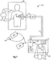
- FIG. 1 illustrates, as an example, a top view of an operating room in which a medical robotic system 100 is being utilized by a Surgeon 20 for performing a medical procedure on a Patient 40 who is lying face up on an operating table 50.
- One or more Assistants 30 may be positioned near the Patient 40 to assist in the procedure while the Surgeon 20 performs the procedure teleoperatively by manipulating input devices 108 , 109 on a surgeon console 10.
- an entry guide (EG) 200 is inserted through a single entry aperture 150 into the Patient 40.
- the entry aperture 150 is a minimally invasive incision in the present example, in the performance of other medical procedures, it may instead be a natural body orifice.
- the entry guide 200 is held and manipulated by a robotic arm assembly 130.
- the robotic arm assembly 130 includes a setup arm and an entry guide manipulator.
- the setup arm is used to position the entry guide 200 at the entry aperture 150 so that it properly enters the entry aperture 150.
- the entry guide manipulator is then used to robotically insert and retract the entry guide 200 into and out of the entry aperture 150. It may also be used to robotically pivot the entry guide 200 in pitch, roll and yaw about a pivot point located at the entry aperture 150.
- An example of such an entry guide manipulator is the entry guide manipulator 202 of FIG. 2 and an example of the four degrees-of-freedom movement that it manipulates the entry guide 200 with is shown in FIG. 5 .
- the console 10 includes a 3-D monitor 104 for displaying a 3-D image of a surgical site to the Surgeon, left and right hand-manipulatable input devices 108 , 109 , and a processor (also referred to herein as a "controller") 102.
- the input devices 108 , 109 may include any one or more of a variety of input devices such as joysticks, gloves, trigger-guns, hand-operated controllers, or the like.
- Other input devices that are provided to allow the Surgeon to interact with the medical robotic system 100 include a foot pedal 105 , a conventional voice recognition system 160 and a Graphical User Interface (GUI) 170.
- GUI Graphical User Interface
- An auxiliary display screen 140 is coupled to the console 10 (and processor 102 ) for providing auxiliary views to the Surgeon to supplement those shown on the monitor 104.
- a second auxiliary display screen 140' is also coupled to the console 10 (and processor 102 ) for providing auxiliary views to the Assistant(s).
- An input device 180 is also coupled to the console to allow the Assistant(s) to select between available auxiliary views for display on the second auxiliary display screen 140'.
- the console 10 is usually located in the same room as the Patient so that the Surgeon may directly monitor the procedure, is physically available if necessary, and is able to speak to the Assistant(s) directly rather than over the telephone or other communication medium.
- the console 10 may be connected to the second auxiliary display screen 140' and input device 180 through a network connection such as a local area network, wide area network, or the Internet.
- the entry guide 200 has articulatable instruments such as articulatable surgical tools 231 , 241 and an articulatable stereo camera 211 extending out of its distal end. Although only two tools 231 , 241 are shown, the entry guide 200 may guide additional tools as required for performing a medical procedure at a work site in the Patient. For example, as shown in FIG. 4 , a passage 351 is available for extending another articulatable surgical tool through the entry guide 200 and out through its distal end. Each of the surgical tools 231 , 241 is associated with one of the input devices 108 , 109 in a tool following mode.
- the Surgeon performs a medical procedure by manipulating the input devices 108 , 109 so that the controller 102 causes corresponding movement of their respectively associated surgical tools 231 , 241 while the Surgeon views the work site in 3-D on the console monitor 104 as images of the work site are being captured by the articulatable camera 211.
- input devices 108 , 109 will be provided with at least the same degrees of freedom as their associated tools 231 , 241 to provide the Surgeon with telepresence, or the perception that the input devices 108 , 109 are integral with the tools 231 , 241 so that the Surgeon has a strong sense of directly controlling the tools 231 , 241.
- the monitor 104 is also positioned near the Surgeon's hands so that it will display a projected image that is oriented so that the Surgeon feels that he or she is actually looking directly down onto the work site and images of the tools 231 , 241 appear to be located substantially where the Surgeon's hands are located.
- the real-time image on the monitor 104 is preferably projected into a perspective image such that the Surgeon can manipulate the end effectors 331 , 341 of the tools 231 , 241 through their corresponding input devices 108 , 109 as if viewing the work site in substantially true presence.
- true presence it is meant that the presentation of an image is a true perspective image simulating the viewpoint of an operator that is physically manipulating the end effectors 331 , 341.
- the processor 102 may transform the coordinates of the end effectors 331 , 341 to a perceived position so that the perspective image being shown on the monitor 104 is the image that the Surgeon would see if the Surgeon was located directly behind the end effectors 331 , 341.
- the processor 102 performs various functions in the system 100.
- One important function that it performs is to translate and transfer the mechanical motion of input devices 108 , 109 through control signals over bus 110 so that the Surgeon can effectively manipulate devices, such as the tools 231, 241 , camera 211 , and entry guide 200 , that are selectively associated with the input devices 108 , 109 at the time.
- Another function is to perform various methods and controller functions described herein.
- processor 102 may be implemented in practice by any combination of hardware, software and firmware. Also, its functions as described herein may be performed by one unit or divided up among different components, each of which may be implemented in turn by any combination of hardware, software and firmware. Further, although being shown as part of or being physically adjacent to the console 10 , the processor 102 may also comprise a number of subunits distributed throughout the system.
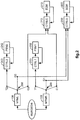
- FIG. 2 illustrates, as an example, a block diagram of components for controlling and selectively associating device manipulators to the input devices 108 , 109.
- Various surgical tools such as graspers, cutters, and needles may be used to perform a medical procedure at a work site within the Patient.
- two surgical tools 231 , 241 are used to robotically perform the procedure and the camera 211 is used to view the procedure.
- the tools 231, 241 and camera 211 are inserted through passages in the entry guide 200.
- the entry guide 200 is inserted into the Patient through entry aperture 150 using the setup portion of the robotic arm assembly 130 and maneuvered by the entry guide manipulator (EGM) 202 of the robotic arm assembly 130 towards the work site where the medical procedure is to be performed.
- EMM entry guide manipulator
- Each of the devices 231 , 241 , 211 , 200 is manipulated by its own manipulator.
- the camera 211 is manipulated by a camera manipulator (ECM) 212
- the first surgical tool 231 is manipulated by a first tool manipulator (PSM1) 232
- the second surgical tool 241 is manipulated by a second tool manipulator (PSM2) 242
- the entry guide 200 is manipulated by an entry guide manipulator (EGM) 202.
- ECM camera manipulator
- the devices 231 , 241 , 211 , 200 are not shown, only their respective manipulators 232 , 242 , 212 , 202 are shown in the figure.
- Each of the instrument manipulators 232 , 242 , 2 12 is a mechanical assembly that carries actuators and provides a mechanical, sterile interface to transmit motion to its respective articulatable instrument.
- Each instrument 231 , 241 , 211 is a mechanical assembly that receives the motion from its manipulator and, by means of a cable transmission, propagates the motion to its distal articulations (e.g., joints). Such joints may be prismatic (e.g., linear motion) or rotational (e.g., they pivot about a mechanical axis).
- the instrument may have internal mechanical constraints (e.g., cables, gearing, cams, belts, etc.) that force multiple joints to move together in a pre-determined fashion.
- Each set of mechanically constrained joints implements a specific axis of motion, and constraints may be devised to pair rotational joints (e.g., joggle joints). Note also that in this way the instrument may have more joints than the available actuators.
- the entry guide manipulator 202 has a different construction and operation. A description of the parts and operation of the entry guide manipulator 202 is described below in reference to FIG. 7 .
- each of the input devices 108 , 109 may be selectively associated with one of the devices 211 , 231 , 241 , 200 so that the associated device may be controlled by the input device through its controller and manipulator.
- the left and right input devices 108 , 109 may be respectively associated with the first and second surgical tools 231 , 241 , which are telerobotically controlled through their respective controllers 233 , 243 (preferably implemented in the processor 102 ) and manipulators 232 , 242 so that the Surgeon may perform a medical procedure on the Patient while the entry guide 200 is locked in place.
- either one or both of the left and right input devices 108 , 109 may be associated with the camera 211 or entry guide 200 so that the Surgeon may move the camera 211 or entry guide 200 through its respective controller ( 213 or 203 ) and manipulator ( 212 or 202 ).
- the disassociated one(s) of the surgical tools 231 , 241 is locked in place relative to the entry guide 200 by its controller.
- the left and right input devices 108 , 109 may be associated with the camera 211 , which is telerobotically controlled through its controller 213 (preferably implemented in the processor 102 ) and manipulator 212 so that the Surgeon may position the camera 211 while the surgical tools 231 , 241 and entry guide 200 are locked in place by their respective controllers 233 , 243 , 203 . If only one input device is to be used for positioning the camera, then only one of the switches 258 , 259 is placed in its camera positioning mode while the other one of the switches 258 , 259 remains in its tool following mode so that its respective input device may continue to control its associated surgical tool.
- the left and right input devices 108 , 109 may be associated with the entry guide 200 , which is telerobotically controlled through its controller 203 (preferably implemented in the processor 102 ) and manipulator 202 so that the Surgeon may position the entry guide 200 while the surgical tools 231 , 241 and camera 211 are locked in place relative to the entry guide 200 by their respective controllers 233 , 243 , 213 .
- the selective association of the input devices 108 , 109 to other devices in this example may be performed by the Surgeon using the GUI 170 or the voice recognition system 160 in a conventional manner.
- the association of the input devices 108 , 109 may be changed by the Surgeon depressing a button on one of the input devices 108 , 109 or depressing the foot pedal 105 , or using any other well known mode switching technique.
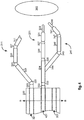
- FIGS. 3-4 respectively illustrate, as examples, top and right side views of a distal end of the entry guide 200 with the camera 211 and surgical tools 231 , 241 extending outward.
- the entry guide 200 is generally cylindrical in shape and has a longitudinal axis X' running centrally along its length.
- the pivot point which is also referred to as a remote center "RC" serves as an origin for both a fixed reference frame having X, Y and Z axes as shown and an entry guide reference frame having X', Y' and Z' axes as shown.
- the entry guide manipulator 202 When the system 100 is in the entry guide positioning mode, the entry guide manipulator 202 is capable of pivoting the entry guide 200 in response to movement of one or more associated input devices about the Z axis (which remains fixed in space) at the remote center "RC" in yaw ⁇ .
- the entry guide manipulator 202 is capable of pivoting the entry guide 200 in response to movement of the one or more input devices about the Y' axis (which is orthogonal to the longitudinal axis X' of the entry guide 200 ) in pitch ⁇ , capable of rotating the entry guide 200 about its longitudinal axis X' in roll ⁇ , and linearly moving the entry guide 200 along its longitudinal axis X' in insertion/retraction or in/out "I/O" directions in response to movement of the one or more associated input devices.
- the X' and Y' axes move with the entry guide 200.
- the entry guide manipulator (EGM) 202 has four actuators 701-704 for actuating the four degrees-of-freedom movement of the entry guide 200 (i.e., pitch ⁇ , yaw ⁇ , roll ⁇ , and in/out I/O) and four corresponding assemblies 711-714 to implement them.
- the articulatable camera 211 extends through passage 321 and the articulatable surgical tools 231, 241 respectively extend through passages 431 , 441 of the entry guide 200.
- the camera 211 includes a tip 311 (which houses a stereo camera connected to a camera controller and a fiber-optic cable connected to an external light source), first, second, and third links 322 , 324 , 326 , first and second joint assemblies (also referred to herein simply as "joints”) 323 , 325 , and a wrist assembly 327.
- the first joint assembly 323 couples the first and second links 322 , 324 and the second joint assembly 325 couples the second and third links 324 , 326 so that the second link 324 may pivot about the first joint assembly 323 in pitch and yaw while the first and third links 322 , 326 remain parallel to each other.
- the first and second joints 323 , 325 are referred to as “joggle joints", because they cooperatively operate together so that as the second link 324 pivots about the first joint 323 in pitch and/or yaw, the third link 326 pivots about the second joint 325 in a complementary fashion so that the first and third links 322 , 326 always remain parallel to each other.
- the first link 322 may also rotate around its longitudinal axis in roll as well as move in and out (e.g., insertion towards the work site and retraction from the worksite) through the passage 321.
- the wrist assembly 327 also has pitch and yaw angular movement capability so that the camera's tip 311 may be oriented up or down and to the right or left, and combinations thereof.
- the joints and links of the tools 231 , 241 are similar in construction and operation to those of the camera 211.
- the tool 231 includes an end effector 331 (having jaws 338 , 339 ), first, second, and third links 332 , 334 , 336 , first and second joint assemblies 333 , 335 , and a wrist assembly 337 that are driven by actuators such as described in reference to FIG. 8 (plus an additional actuator for actuating the end effector 331 ).
- the tool 241 includes an end effector 341 (having jaws 348 , 349 ), first, second, and third links 342 , 344 , 346 , first and second joint assemblies 343 , 345 , and a wrist assembly 347 that are also driven by actuators such as described in reference to FIG. 8 (plus an additional actuator for actuating the end effector 341 ).
- FIG. 8 illustrates, as an example, a diagram of interacting parts of an articulatable instrument (such as the articulatable camera 211 and the articulatable surgical tools 231 , 241 ) and its corresponding instrument manipulator (such as the camera manipulator 212 and the tool manipulators 232 , 242 ).
- Each of the instruments includes a number of actuatable assemblies 821-823 , 831-833 , 870 for effectuating articulation of the instrument (including its end effector), and its corresponding manipulator includes a number of actuators 801-803 , 811-813 , 860 for actuating the actuatable assemblies.
- pitch/yaw coupling mechanisms 840 , 850 (respectively for the joggle joint pitch/yaw and the wrist pitch/yaw) and gear ratios 845 , 855 (respectively for the instrument roll and the end effector actuation) are provided in a sterile manipulator/instrument interface to achieve the required range of motion of the instrument joints in instrument joint space while both satisfying compactness constraints in the manipulator actuator space and preserving accurate transmissions of motion across the interface.
- the coupling between the joggle joint actuators 801 , 802 (differentiated as #1 and #2) and joggle joint pitch/yaw assemblies 821 , 822 may include a pair of coupling mechanisms - one on each side of the sterile interface (i.e., one on the manipulator side of the interface and one on the instrument side of the interface).
- the coupling between the wrist actuators 812 , 813 (differentiated as #1 and #2) and wrist pitch/yaw joint assemblies 832 , 833 may also comprise a pair of coupling mechanisms - one on each side of the sterile interface.
- Both the joggle joint pitch assembly 821 and the joggle joint yaw assembly 822 share the first, second and third links (e.g., links 322 , 324 , 326 of the articulatable camera 211 ) and the first and second joints (e.g., joints 322 , 325 of the articulatable camera 211 ).
- first, second and third links e.g., links 322 , 324 , 326 of the articulatable camera 211
- first and second joints e.g., joints 322 , 325 of the articulatable camera 211
- the joggle joint pitch and yaw assemblies 821 , 822 also include mechanical couplings that couple the first and second joints (through joggle coupling 840 ) to the joggle joint pitch and yaw actuators 801 , 802 so that the second link may controllably pivot about a line passing through the first joint and along an axis that is latitudinal to the longitudinal axis of the first link (e.g., link 322 of the articulatable camera 211 ) and the second link may controllably pivot about a line passing through the first joint and along an axis that is orthogonal to both the latitudinal and longitudinal axes of the first link.
- the second link may controllably pivot about a line passing through the first joint and along an axis that is orthogonal to both the latitudinal and longitudinal axes of the first link.
- the in/out (I/O) assembly 823 includes the first link (e.g., link 322 of the articulatable camera 211 ) and interfaces through a drive train coupling the in/out (I/O) actuator 803 to the first link so that the first link is controllably moved linearly along its longitudinal axis by actuation of the I/O actuator 803.
- the roll assembly 831 includes the first link and interfaces through one or more gears (i.e., having the gear ratio 845 ) that couple a rotating element of the roll actuator 811 (such as a rotor of a motor) to the first link so that the first link is controllably rotated about its longitudinal axis by actuation of the roll actuator 811.
- the instrument manipulator (e.g., camera manipulator 212 ) includes wrist actuators 812 , 813 that actuate through wrist coupling 850 pitch and yaw joints 832 , 833 of the wrist assembly (e.g., wrist 327 of the articulatable camera 211 ) so as to cause the instrument tip (e.g., camera tip 311 ) to controllably pivot in an up-down (i.e., pitch) and side-to-side (i.e., yaw) directions relative to the wrist assembly.
- wrist actuators 812 , 813 that actuate through wrist coupling 850 pitch and yaw joints 832 , 833 of the wrist assembly (e.g., wrist 327 of the articulatable camera 211 ) so as to cause the instrument tip (e.g., camera tip 311 ) to controllably pivot in an up-down (i.e., pitch) and side-to-side (i.e., yaw) directions relative to the wrist assembly.
- the grip assembly 870 includes the end effector (e.g., end effector 331 of the surgical tool 231 ) and interfaces through one or more gears (i.e., having the gear ratio 855 ) that couple the grip actuator 860 to the end effector so as to controllably actuate the end effector.
- the end effector e.g., end effector 331 of the surgical tool 231
- gears i.e., having the gear ratio 855
- FIG. 9 illustrates, as an example, a flow diagram of a method implemented in controller 102 of the medical robotic system 100 for providing a computer generated auxiliary view including articulatable instruments, such as the articulatable camera 211 and/or one or more of the articulatable surgical tools 231 , 241 , extending out of the distal end of the entry guide 200.
- articulatable instruments such as the articulatable camera 211 and/or one or more of the articulatable surgical tools 231 , 241 , extending out of the distal end of the entry guide 200.
- the articulatable camera 211 and surgical tools 231 , 241 extend out of the distal end of the entry guide 200 and are included in the auxiliary view.
- the method is applicable to any combination of articulatable instruments, including those without an articulatable camera and/or those with an alternative type of image capturing device such as an ultrasound probe.
- the method determines whether or not an auxiliary view is to be generated. If the determination in 901 is NO, then the method loops back to periodically check to see whether the situation has changed. On the other hand, if the determination in 901 is YES, then the method proceeds to 902.
- the indication that an auxiliary view is to be generated may be programmed into the controller 102 , created automatically or created by operator command.
- the method receives state information, such as positions and orientations, for each of the instruments 211 , 231 , 241 and the entry guide 200.
- This information may be provided by encoders coupled to the actuators in their respective manipulators 212 , 232 , 242 , 202.
- the information may be provided by sensors coupled to joints and/or links of the instruments 211 , 231 , 241 and the entry guide manipulator 202 , or the coupling mechanisms, gears and drive trains of the interface between corresponding manipulators and instruments, so as to measure their movement.
- the sensors may be included in the instruments 211 , 231 , 241 and entry guide manipulator 202 such as rotation sensors that sense rotational movement of rotary joints and linear sensors that sense linear movement of prismatic joints in the instruments 211 , 231 , 241 and entry guide manipulator 202.
- Other sensors may also be used for providing information of the positions and orientations of the instruments 211 , 231 , 241 and entry guide 200 such as external sensors that sense and track trackable elements, which may be active elements (e.g., radio frequency, electromagnetic, etc.) or passive elements (e.g., magnetic, etc.), placed at strategic points on the instruments 211 , 231 , 241 , the entry guide 200 and/or the entry guide manipulator 202 (such as on their joints, links and/or tips).
- active elements e.g., radio frequency, electromagnetic, etc.
- passive elements e.g., magnetic, etc.
- the method generates a three-dimensional computer model of the articulatable camera 211 and articulatable surgical tools 231 , 241 extending out of the distal end of the entry guide 200 using the information received in 902 and the forward kinematics and known constructions of the instruments 211 , 231 , 241 , entry guide 200 , and entry guide manipulator 202.
- the generated computer model in this example may be referenced to the remote center reference frame (X, Y, Z axes) depicted in FIG. 5 .
- the generated computer model may be referenced to a reference frame defined at the distal end of the entry guide 200. In this latter case, if the orientation and extension of the entry guide 200 from the remote center does not have to be accounted for in the auxiliary view that is being generated by the method, then the position and orientation information for the entry guide 200 may be omitted in 902.
- the state information received in 902 is the instruments' joint positions 1001 , then this information may be applied to the instruments' forward kinematics 1002 using the instruments' kinematic models 1003 to generate the instruments' link positions and orientations 1005 relative to reference frame 1004. The same process may also be generally applied if the state information received in 902 is sensed states of the joggle coupling and gear mechanisms in the manipulator/instrument interfaces.
- the state information received in 902 is the instruments' tip positions 1101 (in the reference frame 1004 )
- this information may be applied to the instruments' inverse kinematics 1102 using the instruments' kinematic models 1003 and the sensor reference frame to generate the instruments' joint positions 1001.
- the instruments' joint positions 1001 may then be applied as described in reference to FIG. 10 to generate the instruments' link positions and orientations 1005 relative to reference frame 1004.
- the positions of the tips of the surgical tools 231 , 241 may be determined relative to the camera reference frame by identifying the tips in the image captured by the camera 211 using conventional image processing techniques and then translating their positions to the reference frame 1004 , so that the positions of the camera and tool tips may be applied as described in reference to FIGS. 10 , 11 to generate the instruments' link positions and orientations 1005 relative to the reference frame 1004.
- the method adjusts the view of the computer model of the articulatable camera 211 and articulatable surgical tools 231 , 241 extending out of the distal end of the entry guide 200 in the three-dimensional space of the reference frame to a specified viewing point (wherein the term "viewing point” is to be understood herein to include position and orientation).
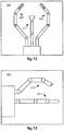
- FIG. 12 illustrates a top view of the articulatable camera 211 and articulatable surgical tools 231 , 241 extending out of the distal end of the entry guide 200 which corresponds to a viewing point above and slightly behind the distal end of the entry guide 200.
- FIG. 12 illustrates a top view of the articulatable camera 211 and articulatable surgical tools 231 , 241 extending out of the distal end of the entry guide 200 which corresponds to a viewing point above and slightly behind the distal end of the entry guide 200.
- FIG. 12 illustrates a top view of the articulatable camera 211 and articulatable surgical tools 231 , 241 extending
- FIGS. 12-13 illustrates a side view of the articulatable camera 211 and articulatable surgical tools 231 , 241 extending out of the distal end of the entry guide 200 which corresponds to a viewing point to the right and slightly in front of the distal end of the entry guide 200.
- the auxiliary views depicted in FIGS. 12-13 are two-dimensional, they may also be three-dimensional views since three-dimensional information is available from the generated computer model. In this latter case, the auxiliary display screen 140 that they are being displayed on would have to be a three-dimensional display screen like the monitor 104.
- the viewing point may be set at a fixed point such as one providing an isometric (three-dimensional) view from the perspective shown in FIG. 12 .
- This perspective provides a clear view to the surgeon of the articulatable camera 211 and the articulatable surgical tools 231 , 241 when the tools 231 , 241 are bent "elbows out” as shown (which is a typical configuration for performing a medical procedure using the surgical tools 231 , 241 ).
- a third surgical tool is being used (e.g., inserted in the passage 351 shown in FIG. 6 )
- a side view from the perspective of FIG. 13 may additionally be useful since the third surgical tool may be beneath the articulatable camera 211 and therefore obscured by it in the perspective shown in FIG. 12 .
- the viewing point may also be automatically changed depending upon the control mode (i.e., one of the modes described in reference to FIG. 2 ) that is operative at the time.
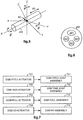
- FIG. 18 illustrates a method for automatically changing the auxiliary viewing mode depending upon the control mode currently operative in the medical robotic system 100.
- a first auxiliary viewing mode is performed in 1802 when the medical robotic system 100 is determined in 1801 to be in a tool following mode
- a second auxiliary viewing mode is performed in 1804 when the medical robotic system 100 is determined in 1803 to be in an entry guide positioning mode
- a third auxiliary viewing mode is performed in 1806 when the medical robotic system 100 is determined in 1805 to be in a camera positioning mode.
- the viewing modes for each control mode are selected so as to be most beneficial to the surgeon for performing actions during that mode.
- either or both the surgical tools 231 , 241 and camera 211 is being moved at the time and therefore, an auxiliary view of the articulatable camera 211 and articulatable surgical tools 231 , 241 extending out of the distal end of the entry guide 200 , such as depicted in FIGS. 12 and 13 , is useful to avoid collisions between links that are out of the field of view of the camera 211.
- the entry guide positioning mode the articulatable camera 211 and the articulatable surgical tools 231 , 241 are locked in position relative to the entry guide 200 and therefore, an auxiliary view providing information on other things such as depicted in FIGS. 16 and 17 may be useful.
- GUI 170 or voice recognition system 160 may be adapted to provide an interactive means for the Surgeon to select the viewing mode and/or change the viewing point of an auxiliary view of the articulatable camera 211 and/or articulatable surgical tools 231 , 241 as they extend out of the distal end of the entry guide 200.
- Buttons on the input devices 108 , 109 or the foot pedal 105 may also be used for Surgeon selection of viewing modes.
- the input device 180 may be used along with a GUI associated with the display screen 140' for selection of viewing modes.
- the viewing modes that the Surgeon and Assistant(s) see at the time may be optimized for their particular tasks at the time. Examples of such operator selectable viewing modes and viewing angles are depicted in FIGS. 12-17 .
- the method renders the computer model.
- Rendering in this case includes adding three-dimensional qualities such as known construction features of the instruments 211 , 231 , 241 and the distal end of the entry guide 200 to the model, filling-in any gaps to make solid models, and providing natural coloring and shading.
- rendering may include altering the color or intensity of one or more of the instruments 211 , 231 , 241 (or one or more of their joints or links or portions thereof) so that the instrument (or joint or link or portion thereof) stands out for identification purposes.
- the altering of the color, intensity, or frequency of blinking on and off (e.g., flashing) of one or more of the instruments 211 , 231 , 241 (or their joints, links, or portions thereof) may serve as a warning that the instrument (or joint or link or portion thereof) is approaching an undesirable event or condition such as nearing a limit of its range of motion or getting too close to or colliding with another one of the instruments.
- the color may go from a first color (e.g., green) to a second color (e.g., yellow) when a warning threshold of an event to be avoided (e.g., range of motion limitation or collision) is reached, and from the second color to a third color (e.g., red) when the event to be avoided is reached.
- a warning threshold of an event to be avoided e.g., range of motion limitation or collision
- a third color e.g., red
- intensity when intensity is used as a warning, the intensity of the color changes as the instrument (or portion thereof) moves past the warning threshold towards the event to be avoided with a maximum intensity provided when the event is reached.
- blinking of the color is used as a warning
- the frequency of blinking changes as the instrument (or portion thereof) moves past the warning threshold towards the event to be avoided with a maximum frequency provided when the event is reached.
- the warning threshold may be based upon a range of motion of the instrument (or portion thereof, such as its joints) or upon a distance between the instrument (or portion thereof) and another instrument (or portion thereof) that it may collide with. Velocity of the instrument's movement may also be a factor in determining the warning threshold.
- the warning threshold may be programmed by the operator, using the GUI 170 , for example, or determined automatically by a programmed algorithm in the processor 102 that takes into account other factors such as the velocity of the instruments' movements.
- the altering of the color, intensity, or frequency of blinking on and off (e.g., flashing) of one or more of the instruments 211 , 231 , 241 (or their joints, links, or portions thereof) may serve as an alert that the instrument (or joint or link or portion thereof) is approaching a desirable event or condition such as an optimal position or configuration for performing or viewing a medical procedure.
- an alert threshold may be defined so that the color, intensity, and/or blinking of the one or more of the instruments 211 , 231 , 241 (or their joints, links, or portions thereof) may change in a similar manner as described previously with respect to warning thresholds and undesirable events or conditions, except that in this case, the change starts when the alert threshold is reached and maximizes or otherwise ends when the desirable event or condition is reached or otherwise achieved.
- the alert threshold may also be programmed by the operator or determined automatically by a programmed algorithm in a conceptually similar manner as the warning threshold.
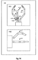
- FIG. 15 shows an auxiliary view of the camera 211 and surgical tools 231 , 241 in a window 1502 , where the camera 211 has been highlighted.
- FIG. 12 shows joints of the surgical tools 231 , 241 that have been highlighted.
- FIG. 14 shows a portion 1402 of the surgical tool 241 and a portion 1403 of the camera 211 highlighted to indicate that these portions are dangerously close to colliding.
- Rendering may also include overlaying the image captured by the camera 211 over the auxiliary view when the viewing point of the auxiliary image is the same as or directly behind that of the camera 211.
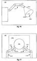
- FIG. 17 illustrates a captured image 1700 of the camera 211 rendered as an overlay to an auxiliary view of surgical tools 231, 241 which has been generated from a viewing point of (or right behind) the camera 211.
- the auxiliary view of the surgical tools 231 , 241 being displayed on the auxiliary display screen 140 (and/or the auxiliary display screen 140' ) includes portions (e.g., 1731 , 1741 ) in the overlaying captured image 1700 and portions (e.g., 1732 , 1742 ) outside of the overlaying captured image 1700.
- the portions of the surgical tools 231 , 241 outside of the captured image 1700 provide the Surgeon with additional information about their respective links or articulating arms that are out of the field of view of the camera 211.
- Highlighting of the instrument portions (e.g., 1732 , 1742 ) outside of the captured image 1700 may also be done for identification purposes or to indicate a warning or alerting condition as described above.
- Overlaying the captured image 1700 onto the auxiliary view also has the advantage in this case of showing an anatomic structure 360 which is in front of the surgical tools 231 , 241 that would not otherwise normally be in the auxiliary view.
- this example shows the captured image 1700 overlaying the auxiliary view on the auxiliary display screen 140 , in another rendering scheme, the auxiliary view may overlay the captured image that is being displayed on the monitor 104.
- rendering may also include using the auxiliary view to augment the image captured by the camera 211 by displaying only the portions of the instruments 231 , 241 that are not seen in the captured image (i.e., the dotted line portion of the instruments 231 , 241 in FIG. 17 ) in proper alignment and adjacent the captured image in a mosaic fashion.
- rendering may also include providing other useful information in the auxiliary view.
- FIG. 16 illustrates an auxiliary side view of an articulatable camera 211 with a frustum 1601 rendered on the auxiliary view so as to be displayed on the auxiliary display 140 as emanating from, and moving with, the camera tip 311.
- the frustum 1601 is shown in the figure as a truncated cone, it may also appear as a truncated pyramid to correspond to the captured image that is shown on the monitor 104.
- FIG. 14 shows a semi-translucent sphere or bubble 1401 (preferably colored red) which is displayed by the method as part of the rendering process when a warning threshold is reached so as to indicate to the operator that the highlighted portions 1402 , 1403 of the surgical tool 241 and camera 211 are dangerously close to colliding.
- the highlighted portions 1402 , 1403 are preferably centered within the sphere.
- the 14 also shows a marker or other indicator 1410 indicating an optimal position for the camera tip 311 for viewing the end effectors of the surgical tools 231 , 241 as they are being used to perform a medical procedure.
- the optimal position may be determined, for example, by finding a location where the tips of the end effectors are equidistant from a center of the captured image.
- the method causes the rendered computer model (i.e., the auxiliary view) to be displayed on one or more displayed screens (e.g., 140 and 140' ) from the perspective of the selected viewing point.
- the auxiliary view is displayed on the auxiliary display screen 140.
- more than one auxiliary view may be displayed at one time (e.g., top and side perspectives may be provided at the same time respectively in windows 1421 and 1422 ).
- the auxiliary view may also be displayed on the primary monitor 104 in a window 1502 that is adjacent to an image captured by the articulatable camera 211 which is being shown in another window 1501.
- the windows 1501 and 1502 appear in this example to be the same size, it is to be appreciated that the position and size of the auxiliary view window 1502 may vary and still be within the scope of the present invention.
- the auxiliary view may be overlayed the captured image in the window 1501 instead of in its own separate window 1502.
- the overlayed auxiliary view may be switched on and off by the Surgeon so as not to clutter the captured image during the performance of a medical procedure.
- the switching on and off in this case may be performed by depressing a button on one of the input devices 108 , 109 or depressing the foot pedal 105.
- voice activation using the voice recognition system 160 or through Surgeon interaction with the GUI 170 or using any other conventional function switching means.
- the method After completing 906 , the method then loops back to 901 to repeat 901-906 for the next processing cycle of the controller 102.
Description
- The present invention generally relates to medical robotic systems and in particular, to a medical robotic system providing an auxiliary view of articulatable instruments extending out of a distal end of an entry guide.
- Medical robotic systems such as teleoperative systems used in performing minimally invasive surgical procedures offer many benefits over traditional open surgery techniques, including less pain, shorter hospital stays, quicker return to normal activities, minimal scarring, reduced recovery time, and less injury to tissue. Consequently, demand for such medical robotic systems is strong and growing.
- One example of such a medical robotic system is the da Vinci® Surgical System from Intuitive Surgical, Inc., of Sunnyvale, California, which is a minimally invasive robotic surgical system. The da Vinci® Surgical System has a number of robotic arms that move attached medical devices, such as an image capturing device and Intuitive Surgical's proprietary EndoWrist® articulating surgical instruments, in response to movement of input devices by a surgeon viewing images captured by the image capturing device of a surgical site. Each of the medical devices is inserted through its own minimally invasive incision into the patient and positioned to perform a medical procedure at the surgical site. The incisions are placed about the patient's body so that the surgical instruments may be used to cooperatively perform the medical procedure and the image capturing device may view it without their robotic arms colliding during the procedure.
- To perform certain medical procedures, it may be advantageous to use a single entry aperture, such as a minimally invasive incision or a natural body orifice, to enter a patient to perform a medical procedure. For example, an entry guide may first be inserted, positioned, and held in place in the entry aperture. Instruments such as an articulatable camera and a plurality of articulatable surgical tools, which are used to perform the medical procedure, may then be inserted into a proximal end of the entry guide so as to extend out of its distal end. Thus, the entry guide provides a single entry aperture for multiple instruments while keeping the instruments bundled together as it guides them toward the work site.
- Since the entry guide generally has a relatively small diameter in order to fit through a minimally invasive incision or a natural body orifice, a number of problems may arise while teleoperating the surgical tools to perform the medical procedure and the camera to view it. For example, because the camera is bundled with the surgical tools, it is limited in its positioning relative to the surgical tools and consequently, its view of the surgical tools.
- Thus, although the tips of the articulatable surgical tools may be kept in the field of view of the camera, controllable linkages which facilitate the articulatability of the surgical tools may not be in the field of view of the camera. As a consequence, the controllable linkages of the surgical tools may inadvertently collide with each other (or with a link of the camera) during the performance of a medical procedure and as a result, cause harm to the patient or otherwise adversely impact the performance of the medical procedure.
- Also, since the articulatable camera is generally incapable of viewing its own controllable linkage, operator movement of the camera is especially a concern where collisions with the surgical tool links are to be avoided. Further, when intuitive control is provided to assist the operator in teleoperatively moving the surgical tools and camera, the motions of the linkages required to produce such intuitive motions of the tips of the tools and camera may not be obvious or intuitive to the operator, thus making it even more difficult for the operator to avoid collisions between linkages that are outside the field of view of the camera.
-
WO 2007/146987 describes a minimally invasive surgical system having master inputs, a guide tube, and instruments and an imaging system extending out of a distal end of the guide tube. In order to avoid collisions between linkages of the instruments, the linkages are viewed within the field of view of the imaging system by withdrawing the imaging system back towards the distal end of the guide tube as necessary. -
US 2006/258938 describes methods and a system for performing tool tracking during minimally invasive robotic surgery. To correct the tool position determined from kinematic information provided by one or more encoders coupled to a robotic mechanism used for manipulating the tool with the tool position determinable from an image captured by a camera assembly, the silhouette of the computer model is compared against the edges of the tool image and its position and orientation modified until a difference between the modified silhouette and the detected edges of the tool image is minimized. - The present invention provides a medical robotic system as set out in the appended claims. Disclosed is a method that provides an auxiliary view to an operator to assist the operator in performing a medical procedure on a patient using a medical robotic system having articulatable instruments extending out of a distal end of an entry guide inserted through a single entry aperture in the patient.
- Also disclosed is a method implemented in such a medical robotic system that provides a visual indication to an operator that indicates when controllable linkages of the articulatable instruments may collide.
- Also disclosed is a method implemented in a medical robotic system that provides a visual indication to an operator that indicates when joints and/or links and/or portions thereof of the articulatable instruments are nearing an undesirable or desirable event or condition.
- Also disclosed is a method implemented in such a medical robotic system that improves an operator's understanding of the configuration of the linkages of the articulatable instruments that are outside of the field of view of a camera.
- Also disclosed is a method for providing a computer generated view, comprising: receiving information of states of one or more articulatable instruments extending out of a distal end of an entry guide; generating a view using the received information and forward kinematics of the one or more articulatable instruments; and displaying the generated view on a display screen.
- The present invention provides a medical robotic system comprising: an entry guide; a plurality of instruments extending through and out of a distal end of the entry guide; wherein the plurality of instruments include an articulatable camera and one or more articulatable surgical tools; one or more input devices for controlling movement of the instruments or the entry guide; an operator selectable means for inputting an operator selection; a plurality of sensors adapted to sense states of articulating elements of the plurality of instruments; a display screen; and characterized by: a controller configured to receive information including the sensed states of the articulating elements from the plurality of sensors, generate a view using the received information, and display the generated view on the display screen, wherein the controller is configured to generate the view by generating a computer model of the plurality of instruments using the received information, translating the computer model to a perspective of a selectable viewing point, and rendering the translated model, and wherein the controller is configured to receive an indication of the selectable viewing point from the operator selectable means, wherein the selectable viewing point is separate from the articulatable camera such that the articulatable camera is within the generated view from the selectable viewing point.
- Additional objects, features and advantages of the various aspects of the present invention will become apparent from the following description of its preferred embodiment, which description should be taken in conjunction with the accompanying drawings.
-
-
FIG. 1 illustrates a top view of an operating room employing a medical robotic system utilizing aspects of the present invention. -
FIG. 2 illustrates a block diagram of components for controlling and selectively associating device manipulators to left and right hand-manipulatable input devices in a medical robotic system utilizing aspects of the present invention. -
FIGS. 3-4 respectively illustrate top and side views of an articulatable camera and a pair of articulatable surgical tools extending out of a distal end of an entry guide as used in a medical robotic system utilizing aspects of the present invention. -
FIG. 5 illustrates a perspective view of an entry guide and its four degrees-of-freedom movement as used in a medical robotic system utilizing aspects of the present invention. -
FIG. 6 illustrates a cross-sectional view of an entry guide with passages defined therein that extend between its proximal and distal ends as used in a medical robotic system utilizing aspects of the present invention. -
FIG. 7 illustrates a block diagram of interacting components of an entry guide manipulator as used in a medical robotic system utilizing aspects of the present invention. -
FIG. 8 illustrates a block diagram of interacting components of an articulatable instrument manipulator and an articulatable instrument as used in a medical robotic system utilizing aspects of the present invention. -
FIG. 9 illustrates a flow diagram of a method for providing a computer generated auxiliary view, utilizing aspects of the present invention. -
FIG. 10 illustrates a data and processing flow diagram to determine instrument link positions and orientations using instrument joint positions and forward kinematics, as used in a medical robotic system utilizing aspects of the present invention. -
FIG. 11 illustrates a data and processing flow diagram to determine instrument joint positions using a sensed instrument tip position and inverse kinematics, as used in a medical robotic system utilizing aspects of the present invention. -
FIGS. 12-13 respectively illustrate top and side auxiliary views as generated and displayed on a display screen by a method implemented in a medical robotic system utilizing aspects of the present invention. -
FIG. 14 illustrates top and side auxiliary views as generated and displayed in separate windows on a display screen by a method implemented in a medical robotic system utilizing aspects of the present invention. -
FIG. 15 illustrates an auxiliary view displayed adjacent to an image captured by the articulatable camera on a monitor in a medical robotic system utilizing aspects of the present invention. -
FIG. 16 illustrates an auxiliary side view of an articulatable camera having a frustum as generated and displayed by a method implemented in a medical robotic system utilizing aspects of the present invention on a display screen. -
FIG. 17 illustrates a combined display of an auxiliary view of a pair of articulatable surgical tools from a viewing point of a camera, along with an image captured by the camera, as generated and displayed by a method implemented in a medical robotic system utilizing aspects of the present invention on a display screen. -
FIG. 18 illustrates a flow diagram of a method for providing auxiliary viewing modes that correspond to device control modes in a medical robotic system, utilizing aspects of the present invention. -
FIG. 1 illustrates, as an example, a top view of an operating room in which a medicalrobotic system 100 is being utilized by aSurgeon 20 for performing a medical procedure on aPatient 40 who is lying face up on an operating table 50. One ormore Assistants 30 may be positioned near thePatient 40 to assist in the procedure while theSurgeon 20 performs the procedure teleoperatively by manipulatinginput devices surgeon console 10. - In the present example, an entry guide (EG) 200 is inserted through a
single entry aperture 150 into thePatient 40. Although theentry aperture 150 is a minimally invasive incision in the present example, in the performance of other medical procedures, it may instead be a natural body orifice. Theentry guide 200 is held and manipulated by arobotic arm assembly 130. - As with other parts of the medical
robotic system 100, the illustration of therobotic arm assembly 130 is simplified inFIG. 1 . In one example of the medicalrobotic system 100, therobotic arm assembly 130 includes a setup arm and an entry guide manipulator. The setup arm is used to position theentry guide 200 at theentry aperture 150 so that it properly enters theentry aperture 150. The entry guide manipulator is then used to robotically insert and retract theentry guide 200 into and out of theentry aperture 150. It may also be used to robotically pivot theentry guide 200 in pitch, roll and yaw about a pivot point located at theentry aperture 150. An example of such an entry guide manipulator is theentry guide manipulator 202 ofFIG. 2 and an example of the four degrees-of-freedom movement that it manipulates theentry guide 200 with is shown inFIG. 5 . - The
console 10 includes a 3-D monitor 104 for displaying a 3-D image of a surgical site to the Surgeon, left and right hand-manipulatable input devices input devices robotic system 100 include afoot pedal 105, a conventionalvoice recognition system 160 and a Graphical User Interface (GUI) 170. - An
auxiliary display screen 140 is coupled to the console 10 (and processor 102) for providing auxiliary views to the Surgeon to supplement those shown on themonitor 104. A second auxiliary display screen 140' is also coupled to the console 10 (and processor 102) for providing auxiliary views to the Assistant(s). Aninput device 180 is also coupled to the console to allow the Assistant(s) to select between available auxiliary views for display on the second auxiliary display screen 140'. - The
console 10 is usually located in the same room as the Patient so that the Surgeon may directly monitor the procedure, is physically available if necessary, and is able to speak to the Assistant(s) directly rather than over the telephone or other communication medium. However, it will be understood that the Surgeon can also be located in a different room, a completely different building, or other remote location from the Patient allowing for remote surgical procedures. In such a case, theconsole 10 may be connected to the second auxiliary display screen 140' andinput device 180 through a network connection such as a local area network, wide area network, or the Internet. - As shown in
FIGS. 3-4 , theentry guide 200 has articulatable instruments such as articulatablesurgical tools articulatable stereo camera 211 extending out of its distal end. Although only twotools entry guide 200 may guide additional tools as required for performing a medical procedure at a work site in the Patient. For example, as shown inFIG. 4 , apassage 351 is available for extending another articulatable surgical tool through theentry guide 200 and out through its distal end. Each of thesurgical tools input devices input devices controller 102 causes corresponding movement of their respectively associatedsurgical tools console monitor 104 as images of the work site are being captured by thearticulatable camera 211. - Preferably,
input devices tools input devices tools tools monitor 104 is also positioned near the Surgeon's hands so that it will display a projected image that is oriented so that the Surgeon feels that he or she is actually looking directly down onto the work site and images of thetools - In addition, the real-time image on the
monitor 104 is preferably projected into a perspective image such that the Surgeon can manipulate theend effectors tools corresponding input devices end effectors processor 102 may transform the coordinates of theend effectors monitor 104 is the image that the Surgeon would see if the Surgeon was located directly behind theend effectors - The
processor 102 performs various functions in thesystem 100. One important function that it performs is to translate and transfer the mechanical motion ofinput devices bus 110 so that the Surgeon can effectively manipulate devices, such as thetools camera 211, andentry guide 200, that are selectively associated with theinput devices - Although described as a processor, it is to be appreciated that the
processor 102 may be implemented in practice by any combination of hardware, software and firmware. Also, its functions as described herein may be performed by one unit or divided up among different components, each of which may be implemented in turn by any combination of hardware, software and firmware. Further, although being shown as part of or being physically adjacent to theconsole 10, theprocessor 102 may also comprise a number of subunits distributed throughout the system. - For additional details on the construction and operation of various aspects of a medical robotic system such as described herein, see, e.g.,
U.S. Pat. No. 6,493,608 "Aspects of a Control System of a Minimally Invasive Surgical Apparatus," andU.S. Pat. No. 6,671,581 "Camera Referenced Control in a Minimally Invasive Surgical Apparatus,". -
FIG. 2 illustrates, as an example, a block diagram of components for controlling and selectively associating device manipulators to theinput devices surgical tools camera 211 is used to view the procedure. Thetools camera 211 are inserted through passages in theentry guide 200. As described in reference toFIG. 1 , theentry guide 200 is inserted into the Patient throughentry aperture 150 using the setup portion of therobotic arm assembly 130 and maneuvered by the entry guide manipulator (EGM) 202 of therobotic arm assembly 130 towards the work site where the medical procedure is to be performed. - Each of the
devices camera 211 is manipulated by a camera manipulator (ECM) 212, the firstsurgical tool 231 is manipulated by a first tool manipulator (PSM1) 232, the secondsurgical tool 241 is manipulated by a second tool manipulator (PSM2) 242, and theentry guide 200 is manipulated by an entry guide manipulator (EGM) 202. So as to not overly encumber the figure, thedevices respective manipulators - Each of the
instrument manipulators instrument - In contrast, the
entry guide manipulator 202 has a different construction and operation. A description of the parts and operation of theentry guide manipulator 202 is described below in reference toFIG. 7 . - In this example, each of the
input devices devices switches right input devices surgical tools respective controllers 233, 243 (preferably implemented in the processor 102) andmanipulators entry guide 200 is locked in place. - When the
camera 211 or theentry guide 200 is to be repositioned by the Surgeon, either one or both of the left andright input devices camera 211 orentry guide 200 so that the Surgeon may move thecamera 211 orentry guide 200 through its respective controller (213 or 203) and manipulator (212 or 202). In this case, the disassociated one(s) of thesurgical tools entry guide 200 by its controller. For example, by placingswitches right input devices camera 211, which is telerobotically controlled through its controller 213 (preferably implemented in the processor 102) andmanipulator 212 so that the Surgeon may position thecamera 211 while thesurgical tools entry guide 200 are locked in place by theirrespective controllers switches switches - On the other hand, by placing
switches right input devices entry guide 200, which is telerobotically controlled through its controller 203 (preferably implemented in the processor 102) andmanipulator 202 so that the Surgeon may position theentry guide 200 while thesurgical tools camera 211 are locked in place relative to theentry guide 200 by theirrespective controllers switches switches - The selective association of the
input devices GUI 170 or thevoice recognition system 160 in a conventional manner. Alternatively, the association of theinput devices input devices foot pedal 105, or using any other well known mode switching technique. -
FIGS. 3-4 respectively illustrate, as examples, top and right side views of a distal end of theentry guide 200 with thecamera 211 andsurgical tools entry guide 200 inFIG. 5 , theentry guide 200 is generally cylindrical in shape and has a longitudinal axis X' running centrally along its length. The pivot point, which is also referred to as a remote center "RC", serves as an origin for both a fixed reference frame having X, Y and Z axes as shown and an entry guide reference frame having X', Y' and Z' axes as shown. When thesystem 100 is in the entry guide positioning mode, theentry guide manipulator 202 is capable of pivoting theentry guide 200 in response to movement of one or more associated input devices about the Z axis (which remains fixed in space) at the remote center "RC" in yaw ψ. In addition, theentry guide manipulator 202 is capable of pivoting theentry guide 200 in response to movement of the one or more input devices about the Y' axis (which is orthogonal to the longitudinal axis X' of the entry guide 200) in pitch θ, capable of rotating theentry guide 200 about its longitudinal axis X' in roll Φ, and linearly moving theentry guide 200 along its longitudinal axis X' in insertion/retraction or in/out "I/O" directions in response to movement of the one or more associated input devices. Note that unlike the Z-axis which is fixed in space, the X' and Y' axes move with theentry guide 200. - As shown in
FIG. 7 , the entry guide manipulator (EGM) 202 has four actuators 701-704 for actuating the four degrees-of-freedom movement of the entry guide 200 (i.e., pitch θ, yaw ψ, roll Φ, and in/out I/O) and four corresponding assemblies 711-714 to implement them. - Referring back to
FIGS. 3-4 , thearticulatable camera 211 extends throughpassage 321 and the articulatablesurgical tools passages entry guide 200. Thecamera 211 includes a tip 311 (which houses a stereo camera connected to a camera controller and a fiber-optic cable connected to an external light source), first, second, andthird links wrist assembly 327. The firstjoint assembly 323 couples the first andsecond links joint assembly 325 couples the second andthird links second link 324 may pivot about the firstjoint assembly 323 in pitch and yaw while the first andthird links - The first and
second joints second link 324 pivots about the first joint 323 in pitch and/or yaw, thethird link 326 pivots about the second joint 325 in a complementary fashion so that the first andthird links first link 322 may also rotate around its longitudinal axis in roll as well as move in and out (e.g., insertion towards the work site and retraction from the worksite) through thepassage 321. Thewrist assembly 327 also has pitch and yaw angular movement capability so that the camera'stip 311 may be oriented up or down and to the right or left, and combinations thereof. - The joints and links of the
tools camera 211. In particular, thetool 231 includes an end effector 331 (havingjaws 338, 339), first, second, andthird links joint assemblies wrist assembly 337 that are driven by actuators such as described in reference toFIG. 8 (plus an additional actuator for actuating the end effector 331). Likewise, thetool 241 includes an end effector 341 (havingjaws 348, 349), first, second, andthird links joint assemblies wrist assembly 347 that are also driven by actuators such as described in reference toFIG. 8 (plus an additional actuator for actuating the end effector 341). -
FIG. 8 illustrates, as an example, a diagram of interacting parts of an articulatable instrument (such as thearticulatable camera 211 and the articulatablesurgical tools 231, 241) and its corresponding instrument manipulator (such as thecamera manipulator 212 and thetool manipulators 232, 242). Each of the instruments includes a number of actuatable assemblies 821-823, 831-833, 870 for effectuating articulation of the instrument (including its end effector), and its corresponding manipulator includes a number of actuators 801-803, 811-813, 860 for actuating the actuatable assemblies. - In addition, a number of interface mechanisms may also be provided. For example, pitch/
yaw coupling mechanisms 840, 850 (respectively for the joggle joint pitch/yaw and the wrist pitch/yaw) andgear ratios 845, 855 (respectively for the instrument roll and the end effector actuation) are provided in a sterile manipulator/instrument interface to achieve the required range of motion of the instrument joints in instrument joint space while both satisfying compactness constraints in the manipulator actuator space and preserving accurate transmissions of motion across the interface. Although shown as asingle block 840, the coupling between the jogglejoint actuators 801, 802 (differentiated as #1 and #2) and joggle joint pitch/yaw assemblies single block 850, the coupling between thewrist actuators 812, 813 (differentiated as #1 and #2) and wrist pitch/yawjoint assemblies - Both the joggle
joint pitch assembly 821 and the jogglejoint yaw assembly 822 share the first, second and third links (e.g.,links yaw assemblies yaw actuators - The in/out (I/O)
assembly 823 includes the first link (e.g., link 322 of the articulatable camera 211) and interfaces through a drive train coupling the in/out (I/O) actuator 803 to the first link so that the first link is controllably moved linearly along its longitudinal axis by actuation of the I/O actuator 803. Theroll assembly 831 includes the first link and interfaces through one or more gears (i.e., having the gear ratio 845) that couple a rotating element of the roll actuator 811 (such as a rotor of a motor) to the first link so that the first link is controllably rotated about its longitudinal axis by actuation of theroll actuator 811. - The instrument manipulator (e.g., camera manipulator 212) includes
wrist actuators wrist coupling 850 pitch andyaw joints wrist 327 of the articulatable camera 211) so as to cause the instrument tip (e.g., camera tip 311) to controllably pivot in an up-down (i.e., pitch) and side-to-side (i.e., yaw) directions relative to the wrist assembly. Thegrip assembly 870 includes the end effector (e.g.,end effector 331 of the surgical tool 231) and interfaces through one or more gears (i.e., having the gear ratio 855) that couple thegrip actuator 860 to the end effector so as to controllably actuate the end effector. -
FIG. 9 illustrates, as an example, a flow diagram of a method implemented incontroller 102 of the medicalrobotic system 100 for providing a computer generated auxiliary view including articulatable instruments, such as thearticulatable camera 211 and/or one or more of the articulatablesurgical tools entry guide 200. For the purposes of this example, it is assumed that thearticulatable camera 211 andsurgical tools entry guide 200 and are included in the auxiliary view. However, it is to be appreciated that the method is applicable to any combination of articulatable instruments, including those without an articulatable camera and/or those with an alternative type of image capturing device such as an ultrasound probe. - In 901, the method determines whether or not an auxiliary view is to be generated. If the determination in 901 is NO, then the method loops back to periodically check to see whether the situation has changed. On the other hand, if the determination in 901 is YES, then the method proceeds to 902. The indication that an auxiliary view is to be generated may be programmed into the
controller 102, created automatically or created by operator command. - In 902, the method receives state information, such as positions and orientations, for each of the
instruments entry guide 200. This information may be provided by encoders coupled to the actuators in theirrespective manipulators instruments entry guide manipulator 202, or the coupling mechanisms, gears and drive trains of the interface between corresponding manipulators and instruments, so as to measure their movement. In this second case, the sensors may be included in theinstruments entry guide manipulator 202 such as rotation sensors that sense rotational movement of rotary joints and linear sensors that sense linear movement of prismatic joints in theinstruments entry guide manipulator 202. Other sensors may also be used for providing information of the positions and orientations of theinstruments entry guide 200 such as external sensors that sense and track trackable elements, which may be active elements (e.g., radio frequency, electromagnetic, etc.) or passive elements (e.g., magnetic, etc.), placed at strategic points on theinstruments entry guide 200 and/or the entry guide manipulator 202 (such as on their joints, links and/or tips). - In 903, the method generates a three-dimensional computer model of the
articulatable camera 211 and articulatablesurgical tools entry guide 200 using the information received in 902 and the forward kinematics and known constructions of theinstruments entry guide 200, andentry guide manipulator 202. The generated computer model in this example may be referenced to the remote center reference frame (X, Y, Z axes) depicted inFIG. 5 . Alternatively, the generated computer model may be referenced to a reference frame defined at the distal end of theentry guide 200. In this latter case, if the orientation and extension of theentry guide 200 from the remote center does not have to be accounted for in the auxiliary view that is being generated by the method, then the position and orientation information for theentry guide 200 may be omitted in 902. - For example, referring to
FIG. 10 , if the state information received in 902 is the instruments'joint positions 1001, then this information may be applied to the instruments'forward kinematics 1002 using the instruments'kinematic models 1003 to generate the instruments' link positions andorientations 1005 relative toreference frame 1004. The same process may also be generally applied if the state information received in 902 is sensed states of the joggle coupling and gear mechanisms in the manipulator/instrument interfaces. - On the other hand, referring to
FIG. 11 , if the state information received in 902 is the instruments' tip positions 1101 (in the reference frame 1004), then this information may be applied to the instruments'inverse kinematics 1102 using the instruments'kinematic models 1003 and the sensor reference frame to generate the instruments'joint positions 1001. The instruments'joint positions 1001 may then be applied as described in reference toFIG. 10 to generate the instruments' link positions andorientations 1005 relative toreference frame 1004. - Alternatively, also referring to
FIG. 11 , if the state information provided in 902 is limited to only the camera's tip position, then the positions of the tips of thesurgical tools camera 211 using conventional image processing techniques and then translating their positions to thereference frame 1004, so that the positions of the camera and tool tips may be applied as described in reference toFIGS. 10, 11 to generate the instruments' link positions andorientations 1005 relative to thereference frame 1004. - In 904, the method adjusts the view of the computer model of the
articulatable camera 211 and articulatablesurgical tools entry guide 200 in the three-dimensional space of the reference frame to a specified viewing point (wherein the term "viewing point" is to be understood herein to include position and orientation). For example,FIG. 12 illustrates a top view of thearticulatable camera 211 and articulatablesurgical tools entry guide 200 which corresponds to a viewing point above and slightly behind the distal end of theentry guide 200. As another example,FIG. 13 illustrates a side view of thearticulatable camera 211 and articulatablesurgical tools entry guide 200 which corresponds to a viewing point to the right and slightly in front of the distal end of theentry guide 200. Note that although the auxiliary views depicted inFIGS. 12-13 are two-dimensional, they may also be three-dimensional views since three-dimensional information is available from the generated computer model. In this latter case, theauxiliary display screen 140 that they are being displayed on would have to be a three-dimensional display screen like themonitor 104. - The viewing point may be set at a fixed point such as one providing an isometric (three-dimensional) view from the perspective shown in
FIG. 12 . This perspective provides a clear view to the surgeon of thearticulatable camera 211 and the articulatablesurgical tools tools surgical tools 231, 241). On the other hand, when a third surgical tool is being used (e.g., inserted in thepassage 351 shown inFIG. 6 ), a side view from the perspective ofFIG. 13 may additionally be useful since the third surgical tool may be beneath thearticulatable camera 211 and therefore obscured by it in the perspective shown inFIG. 12 . - Rather than setting the viewing point to a fixed point at all times, the viewing point may also be automatically changed depending upon the control mode (i.e., one of the modes described in reference to
FIG. 2 ) that is operative at the time. As an example,FIG. 18 illustrates a method for automatically changing the auxiliary viewing mode depending upon the control mode currently operative in the medicalrobotic system 100. In particular, using this method, a first auxiliary viewing mode is performed in 1802 when the medicalrobotic system 100 is determined in 1801 to be in a tool following mode, a second auxiliary viewing mode is performed in 1804 when the medicalrobotic system 100 is determined in 1803 to be in an entry guide positioning mode, and a third auxiliary viewing mode is performed in 1806 when the medicalrobotic system 100 is determined in 1805 to be in a camera positioning mode. The viewing modes for each control mode are selected so as to be most beneficial to the surgeon for performing actions during that mode. For example, in the tool following and camera positioning modes, either or both thesurgical tools camera 211 is being moved at the time and therefore, an auxiliary view of thearticulatable camera 211 and articulatablesurgical tools entry guide 200, such as depicted inFIGS. 12 and 13 , is useful to avoid collisions between links that are out of the field of view of thecamera 211. On the other hand, in the entry guide positioning mode, thearticulatable camera 211 and the articulatablesurgical tools entry guide 200 and therefore, an auxiliary view providing information on other things such as depicted inFIGS. 16 and 17 may be useful. - Alternatively, operator selectable means for changing the viewing point during the performance of a medical procedure may be provided. For example, the
GUI 170 orvoice recognition system 160 may be adapted to provide an interactive means for the Surgeon to select the viewing mode and/or change the viewing point of an auxiliary view of thearticulatable camera 211 and/or articulatablesurgical tools entry guide 200. Buttons on theinput devices foot pedal 105 may also be used for Surgeon selection of viewing modes. For the Assistant(s), theinput device 180 may be used along with a GUI associated with the display screen 140' for selection of viewing modes. Thus, the viewing modes that the Surgeon and Assistant(s) see at the time may be optimized for their particular tasks at the time. Examples of such operator selectable viewing modes and viewing angles are depicted inFIGS. 12-17 . - In 905, the method renders the computer model. Rendering in this case includes adding three-dimensional qualities such as known construction features of the
instruments entry guide 200 to the model, filling-in any gaps to make solid models, and providing natural coloring and shading. In addition, rendering may include altering the color or intensity of one or more of theinstruments - Alternatively, the altering of the color, intensity, or frequency of blinking on and off (e.g., flashing) of one or more of the
instruments GUI 170, for example, or determined automatically by a programmed algorithm in theprocessor 102 that takes into account other factors such as the velocity of the instruments' movements. - Alternatively, the altering of the color, intensity, or frequency of blinking on and off (e.g., flashing) of one or more of the
instruments instruments - As an example of such highlighting of an instrument for identification, warning or alerting purposes,
FIG. 15 shows an auxiliary view of thecamera 211 andsurgical tools window 1502, where thecamera 211 has been highlighted. As an example of such highlighting of joints of instruments for identification, warning or alerting purposes,FIG. 12 shows joints of thesurgical tools FIG. 14 shows aportion 1402 of thesurgical tool 241 and aportion 1403 of thecamera 211 highlighted to indicate that these portions are dangerously close to colliding. - Rendering may also include overlaying the image captured by the
camera 211 over the auxiliary view when the viewing point of the auxiliary image is the same as or directly behind that of thecamera 211. As an example,FIG. 17 illustrates a capturedimage 1700 of thecamera 211 rendered as an overlay to an auxiliary view ofsurgical tools camera 211. In this example, the auxiliary view of thesurgical tools image 1700 and portions (e.g., 1732, 1742) outside of the overlaying capturedimage 1700. Thus, the portions of thesurgical tools image 1700 provide the Surgeon with additional information about their respective links or articulating arms that are out of the field of view of thecamera 211. Highlighting of the instrument portions (e.g., 1732, 1742) outside of the capturedimage 1700 may also be done for identification purposes or to indicate a warning or alerting condition as described above. Overlaying the capturedimage 1700 onto the auxiliary view also has the advantage in this case of showing ananatomic structure 360 which is in front of thesurgical tools image 1700 overlaying the auxiliary view on theauxiliary display screen 140, in another rendering scheme, the auxiliary view may overlay the captured image that is being displayed on themonitor 104. - Rather than overlaying the captured image, rendering may also include using the auxiliary view to augment the image captured by the
camera 211 by displaying only the portions of theinstruments instruments FIG. 17 ) in proper alignment and adjacent the captured image in a mosaic fashion. - In addition to, or in lieu of, overlaying the captured image over the auxiliary view or augmenting the captured image with the auxiliary view, rendering may also include providing other useful information in the auxiliary view. As an example,
FIG. 16 illustrates an auxiliary side view of anarticulatable camera 211 with afrustum 1601 rendered on the auxiliary view so as to be displayed on theauxiliary display 140 as emanating from, and moving with, thecamera tip 311. Note that although thefrustum 1601 is shown in the figure as a truncated cone, it may also appear as a truncated pyramid to correspond to the captured image that is shown on themonitor 104. The sides of thefrustum 1601 indicate a viewing range of thecamera 211 and thebase 1602 of thefrustum 1601 displays animage 1650 that was captured by thecamera 211. Note that for simplification purposes, thesurgical tools FIG. 14 shows a semi-translucent sphere or bubble 1401 (preferably colored red) which is displayed by the method as part of the rendering process when a warning threshold is reached so as to indicate to the operator that the highlightedportions surgical tool 241 andcamera 211 are dangerously close to colliding. In this case, the highlightedportions FIG. 14 also shows a marker orother indicator 1410 indicating an optimal position for thecamera tip 311 for viewing the end effectors of thesurgical tools - In 906, the method causes the rendered computer model (i.e., the auxiliary view) to be displayed on one or more displayed screens (e.g., 140 and 140') from the perspective of the selected viewing point. As shown in
FIGS. 12-14 and 16-17, the auxiliary view is displayed on theauxiliary display screen 140. As shown inFIG. 14 , more than one auxiliary view may be displayed at one time (e.g., top and side perspectives may be provided at the same time respectively inwindows 1421 and 1422). As shown inFIG. 15 , the auxiliary view may also be displayed on theprimary monitor 104 in awindow 1502 that is adjacent to an image captured by thearticulatable camera 211 which is being shown in anotherwindow 1501. Although thewindows auxiliary view window 1502 may vary and still be within the scope of the present invention. Also, as previously mentioned, the auxiliary view may be overlayed the captured image in thewindow 1501 instead of in its ownseparate window 1502. In such case, the overlayed auxiliary view may be switched on and off by the Surgeon so as not to clutter the captured image during the performance of a medical procedure. The switching on and off in this case may be performed by depressing a button on one of theinput devices foot pedal 105. Alternatively, it may be done by voice activation using thevoice recognition system 160 or through Surgeon interaction with theGUI 170 or using any other conventional function switching means. - After completing 906, the method then loops back to 901 to repeat 901-906 for the next processing cycle of the
controller 102. - Although the various aspects of the present invention have been described with respect to a preferred embodiment, it will be understood that the invention is entitled to full protection within the full scope of the appended claims.
Claims (15)
- A medical robotic system (100) comprising:an entry guide (200); a plurality of instruments (211, 231, 241) extending through and out of a distal end of the entry guide (200), wherein the plurality of instruments (211, 231, 241) include an articulatable camera (211) and one or more articulatable surgical tools (231, 241); one or more input devices (108, 109) for controlling movement of the instruments (211, 231, 241) or the entry guide (200); an operator selectable means (170, 160, 105) for inputting an operator selection; a plurality of sensors adapted to sense states of articulating elements of the plurality of instruments (211, 231, 241); a display screen (104); andcharacterized by:a controller (102) configured to receive information including the sensed states of the articulating elements from the plurality of sensors, generate a view using the received information, and display the generated view on the display screen (104),wherein the controller (102) is configured to generate the view by generating a computer model of the plurality of instruments (211, 231, 241) using the received information, translating the computer model to a perspective of a selectable viewing point, and rendering the translated model, andwherein the controller (102) is configured to receive an indication of the selectable viewing point from the operator selectable means (170, 160, 105), wherein the selectable viewing point is separate from the articulatable camera such that the articulatable camera is within the generated view from the selectable viewing point.
- A medical robotic system according to claim 1, wherein the selectable view is from a first position and orientation when the one or more input devices (108, 109) are associated with the entry guide (200) for repositioning of the entry guide (200), the selectable view is from a second position and orientation when the one or more input devices (108, 109) are associated with the one or more articulatable surgical tools (231, 241) for performing a procedure using the tools (231, 241), and the selectable view is from a third position and orientation when the one or more input devices (108, 109) are associated with the articulatable camera (211) for moving the articulatable camera (211) so as to capture an image from a different perspective.
- The medical robotic system (100) according to claim 1, wherein the articulating elements include actuators for articulating the plurality of instruments (211, 231, 241), or
wherein the articulating elements include joints and the plurality of sensors include rotation sensors that sense rotational movement of the joints, or
wherein the articulating elements include links and the plurality of sensors include translation sensors that sense linear movement of the links, or
wherein the plurality of sensors are disposed within the plurality of instruments (211, 231, 241), or wherein the plurality of sensors are external of the plurality of instruments (211, 231, 241) so as to sense states of trackable elements placed at strategic points on the plurality of instruments (211, 231, 241). - The medical robotic system (100) according to claim 1,
wherein the controller (102) generates the computer model by computing forward kinematics of the plurality of instruments (211, 231, 241) with respect to a fixed reference point. - The medical robotic system (100) according to claim 1, wherein the controller (102) is configured to generate the computer model by computing forward kinematics of the plurality of instruments (211, 231, 241) with respect to a fixed reference point that is a remote center about which the entry guide (200) is pivotable.
- The medical robotic system (100) according to claim 4, wherein the controller (102) is configured to translate the computer model to the perspective of the selectable viewing point by computing a distance from the fixed reference point to the selectable viewing point and translating and orienting the computer model to the perspective of the selectable viewing point using the computed distance.
- The medical robotic system (100) according to claim 1, wherein the controller (102) is configured to render the translated computer model by rendering the articulatable camera (211) in a different color than others of the plurality of instruments (211, 231, 241) so that the articulatable camera (211) may be readily distinguished in the view being displayed on the display screen (104).
- The medical robotic system (100) according to claim 1, wherein the controller (102) is configured to render the translated computer model by changing a color of at least a portion of at least one of the plurality of instruments (211, 231, 241) as the at least one of the plurality of instruments (211, 231, 241) reaches a threshold of an event, and preferably
wherein the threshold is a warning threshold and the event is a condition to be avoided, and preferably
wherein the warning threshold is based upon a range of motion of the portion of the at least one of the plurality of instruments (211, 231, 241), and preferably
wherein the condition to be avoided is a limitation of the range of motion of the portion of the at least one of the plurality of instruments (211, 231, 241). - The medical robotic system (100) according to claim 8, wherein the warning threshold is based upon a distance between the portion of the at least one of the plurality of instruments (211, 231, 241) and a portion of another of the plurality of instruments (211, 231, 241), and preferably
wherein the condition to be avoided is a collision between the portion of the at least one of the plurality of instruments (211, 231, 241) and the portion of the another of the plurality of instruments (211, 231, 241), and preferably
wherein the portion of the another of the plurality of instruments (211, 231, 241) changes color as the portion of the at least one of the plurality of instruments (211, 231, 241) reaches the warning threshold, and preferably
wherein a sphere is displayed around the portion of the at least one of the plurality of instruments (211, 231, 241) and the portion of the another of the plurality of instruments (211, 231, 241) as the portion of the at least one of the plurality of instruments (211, 231, 241) reaches the warning threshold. - The medical robotic system (100) according to claim 8, wherein an intensity of the color changes as the portion of the at least one of the plurality of instruments (211, 231, 241) moves beyond the warning threshold towards the event to be avoided, or
wherein the color turns on and off at a frequency that increases as the portion of the at least one of the plurality of instruments (211, 231, 241) moves beyond the warning threshold towards the event to be avoided, or
wherein the color changes from a first color to a second color when the portion of the at least one of the plurality of instruments (211, 231, 241) reaches the warning threshold and from the second color to third color as the portion of the at least one of the plurality of instruments (211, 231, 241) reaches the event to be avoided. - The medical robotic system (100) according to claim 8, wherein the threshold is an alert threshold and the event is a desirable position for the at least one of the one or more articulatable instruments (211, 231, 241), or
wherein the threshold is an alert threshold and the event is a desirable configuration for the at least one of the one or more articulatable instruments (211, 231, 241). - The medical robotic system (100) according to claim 1, wherein the articulatable camera (211) includes a stereoscopic camera and an image captured by the articulatable camera (211) is displayed as a three-dimensional image on the display screen (104) adjacent the displayed view of the one or more surgical tools (231, 241) extending out of the distal end of the entry guide (200), and preferably
wherein the displayed view of the one or more surgical tools (231, 241) extending out of the distal end of the entry guide (200) is a three-dimensional view. - The medical robotic system (100) according to claim 1, wherein the controller (102) is configured to generate the computer model by generating a frustum so as to extend out from a tip of the articulatable camera (211) and indicate the viewing range of the articulatable camera (211).
- The medical robotic system (100) according to claim 13, wherein the controller (102) is configured to render the translated computer model by rendering an image captured by the articulatable camera (211) on a base of the frustum.
- The medical robotic system (100) according to claim 1, wherein the controller (102) is configured to calculate a centroid for the plurality of instruments (211, 231, 241) and display the view on the display screen (104) by displaying the centroid on the display screen (104) so as to provide an indication of whether the entry guide (200) needs to be repositioned.
Priority Applications (1)
| Application Number | Priority Date | Filing Date | Title |
|---|---|---|---|
| EP18158957.3A EP3351203B1 (en) | 2008-06-27 | 2009-06-04 | Medical robotic system providing an auxiliary view of articulatable instruments extending out of a distal end of an entry guide |
Applications Claiming Priority (2)
| Application Number | Priority Date | Filing Date | Title |
|---|---|---|---|
| US12/163,087 US10258425B2 (en) | 2008-06-27 | 2008-06-27 | Medical robotic system providing an auxiliary view of articulatable instruments extending out of a distal end of an entry guide |
| PCT/US2009/046234 WO2009158164A1 (en) | 2008-06-27 | 2009-06-04 | Medical robotic system providing an auxiliary view of articulatable instruments extending out of a distal end of an entry guide |
Related Child Applications (1)
| Application Number | Title | Priority Date | Filing Date |
|---|---|---|---|
| EP18158957.3A Division EP3351203B1 (en) | 2008-06-27 | 2009-06-04 | Medical robotic system providing an auxiliary view of articulatable instruments extending out of a distal end of an entry guide |
Publications (2)
| Publication Number | Publication Date |
|---|---|
| EP2326277A1 EP2326277A1 (en) | 2011-06-01 |
| EP2326277B1 true EP2326277B1 (en) | 2018-03-21 |
Family
ID=40974669
Family Applications (2)
| Application Number | Title | Priority Date | Filing Date |
|---|---|---|---|
| EP18158957.3A Active EP3351203B1 (en) | 2008-06-27 | 2009-06-04 | Medical robotic system providing an auxiliary view of articulatable instruments extending out of a distal end of an entry guide |
| EP09770698.0A Active EP2326277B1 (en) | 2008-06-27 | 2009-06-04 | Medical robotic system providing an auxiliary view of articulatable instruments extending out of a distal end of an entry guide |
Family Applications Before (1)
| Application Number | Title | Priority Date | Filing Date |
|---|---|---|---|
| EP18158957.3A Active EP3351203B1 (en) | 2008-06-27 | 2009-06-04 | Medical robotic system providing an auxiliary view of articulatable instruments extending out of a distal end of an entry guide |
Country Status (6)
| Country | Link |
|---|---|
| US (3) | US10258425B2 (en) |
| EP (2) | EP3351203B1 (en) |
| JP (3) | JP5583123B2 (en) |
| KR (3) | KR101663568B1 (en) |
| CN (2) | CN102076276B (en) |
| WO (1) | WO2009158164A1 (en) |
Families Citing this family (214)
| Publication number | Priority date | Publication date | Assignee | Title |
|---|---|---|---|---|
| US8944070B2 (en) | 1999-04-07 | 2015-02-03 | Intuitive Surgical Operations, Inc. | Non-force reflecting method for providing tool force information to a user of a telesurgical system |
| US8073528B2 (en) | 2007-09-30 | 2011-12-06 | Intuitive Surgical Operations, Inc. | Tool tracking systems, methods and computer products for image guided surgery |
| US10555775B2 (en) | 2005-05-16 | 2020-02-11 | Intuitive Surgical Operations, Inc. | Methods and system for performing 3-D tool tracking by fusion of sensor and/or camera derived data during minimally invasive robotic surgery |
| US9789608B2 (en) | 2006-06-29 | 2017-10-17 | Intuitive Surgical Operations, Inc. | Synthetic representation of a surgical robot |
| US8971597B2 (en) | 2005-05-16 | 2015-03-03 | Intuitive Surgical Operations, Inc. | Efficient vision and kinematic data fusion for robotic surgical instruments and other applications |
| US9962066B2 (en) | 2005-12-30 | 2018-05-08 | Intuitive Surgical Operations, Inc. | Methods and apparatus to shape flexible entry guides for minimally invasive surgery |
| US7930065B2 (en) | 2005-12-30 | 2011-04-19 | Intuitive Surgical Operations, Inc. | Robotic surgery system including position sensors using fiber bragg gratings |
| US8182415B2 (en) | 2006-06-13 | 2012-05-22 | Intuitive Surgical Operations, Inc. | Minimally invasive surgical system |
| US10008017B2 (en) | 2006-06-29 | 2018-06-26 | Intuitive Surgical Operations, Inc. | Rendering tool information as graphic overlays on displayed images of tools |
| US9718190B2 (en) | 2006-06-29 | 2017-08-01 | Intuitive Surgical Operations, Inc. | Tool position and identification indicator displayed in a boundary area of a computer display screen |
| US20090192523A1 (en) | 2006-06-29 | 2009-07-30 | Intuitive Surgical, Inc. | Synthetic representation of a surgical instrument |
| US10258425B2 (en) | 2008-06-27 | 2019-04-16 | Intuitive Surgical Operations, Inc. | Medical robotic system providing an auxiliary view of articulatable instruments extending out of a distal end of an entry guide |
| US9089256B2 (en) | 2008-06-27 | 2015-07-28 | Intuitive Surgical Operations, Inc. | Medical robotic system providing an auxiliary view including range of motion limitations for articulatable instruments extending out of a distal end of an entry guide |
| US9469034B2 (en) | 2007-06-13 | 2016-10-18 | Intuitive Surgical Operations, Inc. | Method and system for switching modes of a robotic system |
| US9084623B2 (en) * | 2009-08-15 | 2015-07-21 | Intuitive Surgical Operations, Inc. | Controller assisted reconfiguration of an articulated instrument during movement into and out of an entry guide |
| US8620473B2 (en) * | 2007-06-13 | 2013-12-31 | Intuitive Surgical Operations, Inc. | Medical robotic system with coupled control modes |
| US8903546B2 (en) * | 2009-08-15 | 2014-12-02 | Intuitive Surgical Operations, Inc. | Smooth control of an articulated instrument across areas with different work space conditions |
| US9138129B2 (en) | 2007-06-13 | 2015-09-22 | Intuitive Surgical Operations, Inc. | Method and system for moving a plurality of articulated instruments in tandem back towards an entry guide |
| US8864652B2 (en) | 2008-06-27 | 2014-10-21 | Intuitive Surgical Operations, Inc. | Medical robotic system providing computer generated auxiliary views of a camera instrument for controlling the positioning and orienting of its tip |
| US8848974B2 (en) * | 2008-09-29 | 2014-09-30 | Restoration Robotics, Inc. | Object-tracking systems and methods |
| US8830224B2 (en) | 2008-12-31 | 2014-09-09 | Intuitive Surgical Operations, Inc. | Efficient 3-D telestration for local robotic proctoring |
| US8184880B2 (en) * | 2008-12-31 | 2012-05-22 | Intuitive Surgical Operations, Inc. | Robust sparse image matching for robotic surgery |
| US9155592B2 (en) | 2009-06-16 | 2015-10-13 | Intuitive Surgical Operations, Inc. | Virtual measurement tool for minimally invasive surgery |
| US9492927B2 (en) | 2009-08-15 | 2016-11-15 | Intuitive Surgical Operations, Inc. | Application of force feedback on an input device to urge its operator to command an articulated instrument to a preferred pose |
| US8918211B2 (en) | 2010-02-12 | 2014-12-23 | Intuitive Surgical Operations, Inc. | Medical robotic system providing sensory feedback indicating a difference between a commanded state and a preferred pose of an articulated instrument |
| KR101161242B1 (en) | 2010-02-17 | 2012-07-02 | 전남대학교산학협력단 | Tubular type manipulator surgical robot system with image guidance for minimal invasive surgery |
| KR101151738B1 (en) | 2010-02-17 | 2012-06-15 | 전남대학교산학협력단 | Tubular type manipulator with multi-articulated end-effector for surgical robot |
| US9888973B2 (en) * | 2010-03-31 | 2018-02-13 | St. Jude Medical, Atrial Fibrillation Division, Inc. | Intuitive user interface control for remote catheter navigation and 3D mapping and visualization systems |
| US8746252B2 (en) | 2010-05-14 | 2014-06-10 | Intuitive Surgical Operations, Inc. | Surgical system sterile drape |
| US9486189B2 (en) | 2010-12-02 | 2016-11-08 | Hitachi Aloka Medical, Ltd. | Assembly for use with surgery system |
| US9498289B2 (en) | 2010-12-21 | 2016-11-22 | Restoration Robotics, Inc. | Methods and systems for directing movement of a tool in hair transplantation procedures |
| US8911453B2 (en) | 2010-12-21 | 2014-12-16 | Restoration Robotics, Inc. | Methods and systems for directing movement of a tool in hair transplantation procedures |
| JP5501290B2 (en) * | 2011-05-23 | 2014-05-21 | 富士フイルム株式会社 | Image processing apparatus, radiographic image capturing system, and image processing program |
| CA3082073C (en) | 2011-07-11 | 2023-07-25 | Board Of Regents Of The University Of Nebraska | Robotic surgical devices, systems, and related methods |
| US20130303944A1 (en) | 2012-05-14 | 2013-11-14 | Intuitive Surgical Operations, Inc. | Off-axis electromagnetic sensor |
| US9387048B2 (en) | 2011-10-14 | 2016-07-12 | Intuitive Surgical Operations, Inc. | Catheter sensor systems |
| US9452276B2 (en) | 2011-10-14 | 2016-09-27 | Intuitive Surgical Operations, Inc. | Catheter with removable vision probe |
| US10238837B2 (en) | 2011-10-14 | 2019-03-26 | Intuitive Surgical Operations, Inc. | Catheters with control modes for interchangeable probes |
| US9586323B2 (en) * | 2012-02-15 | 2017-03-07 | Intuitive Surgical Operations, Inc. | User selection of robotic system operating modes using mode distinguishing operator actions |
| KR101946000B1 (en) * | 2012-03-28 | 2019-02-08 | 삼성전자주식회사 | Robot system and Control Method thereof for surgery |
| US9498292B2 (en) | 2012-05-01 | 2016-11-22 | Board Of Regents Of The University Of Nebraska | Single site robotic device and related systems and methods |
| US9225412B2 (en) | 2012-05-02 | 2015-12-29 | Samsung Electronics Co., Ltd. | Communication system with feedback mechanism and method of operation thereof |
| US11871901B2 (en) | 2012-05-20 | 2024-01-16 | Cilag Gmbh International | Method for situational awareness for surgical network or surgical network connected device capable of adjusting function based on a sensed situation or usage |
| US11253327B2 (en) * | 2012-06-21 | 2022-02-22 | Globus Medical, Inc. | Systems and methods for automatically changing an end-effector on a surgical robot |
| CA2880622C (en) | 2012-08-08 | 2021-01-12 | Board Of Regents Of The University Of Nebraska | Robotic surgical devices, systems and related methods |
| US9770305B2 (en) | 2012-08-08 | 2017-09-26 | Board Of Regents Of The University Of Nebraska | Robotic surgical devices, systems, and related methods |
| KR102146796B1 (en) | 2012-08-15 | 2020-08-21 | 인튜어티브 서지컬 오퍼레이션즈 인코포레이티드 | Phantom degrees of freedom in joint estimation and control |
| WO2014028557A1 (en) | 2012-08-15 | 2014-02-20 | Intuitive Surgical Operations, Inc. | Phantom degrees of freedom for manipulating the movement of mechanical bodies |
| JP6255402B2 (en) * | 2012-08-15 | 2017-12-27 | インテュイティブ サージカル オペレーションズ, インコーポレイテッド | Phantom degrees of freedom for manipulating the movement of the surgical system |
| US8836937B2 (en) * | 2012-11-19 | 2014-09-16 | General Electric Company | Actuatable visual inspection device |
| CN105188590B (en) | 2012-12-10 | 2019-04-26 | 直观外科手术操作公司 | Image collecting device and can the collision during manipulation device lever arm controlled motion avoid |
| US10507066B2 (en) | 2013-02-15 | 2019-12-17 | Intuitive Surgical Operations, Inc. | Providing information of tools by filtering image areas adjacent to or on displayed images of the tools |
| WO2014144220A1 (en) | 2013-03-15 | 2014-09-18 | Board Of Regents Of The University Of Nebraska | Robotic surgical devices, systems, and related methdos |
| CN105073057B (en) | 2013-03-18 | 2017-07-04 | 奥林巴斯株式会社 | Manipulator |
| EP2996613B1 (en) * | 2013-06-19 | 2017-06-07 | Titan Medical Inc. | Articulated tool positioner and system employing same |
| JP6479790B2 (en) | 2013-07-17 | 2019-03-06 | ボード オブ リージェンツ オブ ザ ユニバーシティ オブ ネブラスカ | Robotic surgical device, system and related methods |
| JP6173089B2 (en) | 2013-07-24 | 2017-08-02 | オリンパス株式会社 | Control method for medical master-slave system |
| US10945796B2 (en) * | 2014-02-12 | 2021-03-16 | Koninklijke Philips N.V. | Robotic control of surgical instrument visibility |
| JP6165080B2 (en) * | 2014-02-21 | 2017-07-19 | オリンパス株式会社 | Initialization method of manipulator system |
| JP6353665B2 (en) | 2014-02-21 | 2018-07-04 | オリンパス株式会社 | Manipulator initialization method, manipulator, and manipulator system |
| US10398521B2 (en) * | 2014-03-17 | 2019-09-03 | Intuitive Surgical Operations, Inc. | System and method for recentering imaging devices and input controls |
| US11504192B2 (en) | 2014-10-30 | 2022-11-22 | Cilag Gmbh International | Method of hub communication with surgical instrument systems |
| EP3254637A4 (en) * | 2015-02-06 | 2018-10-24 | Olympus Corporation | Medical manipulator system |
| EP3261574A4 (en) * | 2015-02-26 | 2018-10-31 | Covidien LP | Robotically controlling remote center of motion with software and guide tube |
| US10959783B2 (en) * | 2015-04-15 | 2021-03-30 | Mobius Imaging, Llc | Integrated medical imaging and surgical robotic system |
| WO2016176755A1 (en) | 2015-05-01 | 2016-11-10 | Titan Medical Inc. | Instrument collision detection and feedback |
| EP3305161A4 (en) * | 2015-05-28 | 2019-01-09 | Olympus Corporation | Endoscope system |
| EP3324874B1 (en) * | 2015-07-17 | 2021-11-10 | DEKA Products Limited Partnership | Robotic surgery system |
| WO2017024081A1 (en) | 2015-08-03 | 2017-02-09 | Board Of Regents Of The University Of Nebraska | Robotic surgical devices systems and related methods |
| WO2017103984A1 (en) * | 2015-12-15 | 2017-06-22 | オリンパス株式会社 | Medical manipulator system and operation method therefor |
| EP3397184A1 (en) * | 2015-12-29 | 2018-11-07 | Koninklijke Philips N.V. | System, control unit and method for control of a surgical robot |
| WO2017122322A1 (en) | 2016-01-14 | 2017-07-20 | オリンパス株式会社 | Medical manipulator system |
| EP3429496A1 (en) * | 2016-03-17 | 2019-01-23 | Koninklijke Philips N.V. | Control unit, system and method for controlling hybrid robot having rigid proximal portion and flexible distal portion |
| EP3457951B1 (en) | 2016-05-18 | 2024-03-06 | Virtual Incision Corporation | Robotic surgical devices and systems |
| EP4238490A3 (en) * | 2016-06-30 | 2023-11-01 | Intuitive Surgical Operations, Inc. | Graphical user interface for displaying guidance information during an image-guided procedure |
| WO2018013198A1 (en) * | 2016-07-14 | 2018-01-18 | Intuitive Surgical Operations, Inc. | Systems and methods for displaying an instrument navigator in a teleoperational system |
| EP3484402A4 (en) | 2016-07-14 | 2020-03-25 | Intuitive Surgical Operations Inc. | Secondary instrument control in a computer-assisted teleoperated system |
| EP3515348A4 (en) * | 2016-09-19 | 2020-05-20 | Intuitive Surgical Operations Inc. | Base positioning system for a controllable arm and related methods |
| GB201703878D0 (en) * | 2017-03-10 | 2017-04-26 | Cambridge Medical Robotics Ltd | Control system |
| AU2018250049B2 (en) * | 2017-04-07 | 2023-06-29 | Auris Health, Inc. | Patient introducer alignment |
| EP3612121A4 (en) | 2017-04-18 | 2021-04-07 | Intuitive Surgical Operations, Inc. | Graphical user interface for monitoring an image-guided procedure |
| US10242548B2 (en) * | 2017-05-23 | 2019-03-26 | Biosense Webster (Israel) Ltd. | Medical tool puncture warning method and apparatus |
| CN107049492B (en) * | 2017-05-26 | 2020-02-21 | 微创(上海)医疗机器人有限公司 | Surgical robot system and method for displaying position of surgical instrument |
| KR102562537B1 (en) * | 2017-08-22 | 2023-08-03 | 인튜어티브 서지컬 오퍼레이션즈 인코포레이티드 | User installable part installation detection technology |
| US11317919B2 (en) | 2017-10-30 | 2022-05-03 | Cilag Gmbh International | Clip applier comprising a clip crimping system |
| US11564756B2 (en) | 2017-10-30 | 2023-01-31 | Cilag Gmbh International | Method of hub communication with surgical instrument systems |
| US11911045B2 (en) | 2017-10-30 | 2024-02-27 | Cllag GmbH International | Method for operating a powered articulating multi-clip applier |
| US11129636B2 (en) | 2017-10-30 | 2021-09-28 | Cilag Gmbh International | Surgical instruments comprising an articulation drive that provides for high articulation angles |
| US11801098B2 (en) | 2017-10-30 | 2023-10-31 | Cilag Gmbh International | Method of hub communication with surgical instrument systems |
| US11510741B2 (en) | 2017-10-30 | 2022-11-29 | Cilag Gmbh International | Method for producing a surgical instrument comprising a smart electrical system |
| US11406390B2 (en) | 2017-10-30 | 2022-08-09 | Cilag Gmbh International | Clip applier comprising interchangeable clip reloads |
| US11311342B2 (en) | 2017-10-30 | 2022-04-26 | Cilag Gmbh International | Method for communicating with surgical instrument systems |
| US11229436B2 (en) | 2017-10-30 | 2022-01-25 | Cilag Gmbh International | Surgical system comprising a surgical tool and a surgical hub |
| US11291510B2 (en) | 2017-10-30 | 2022-04-05 | Cilag Gmbh International | Method of hub communication with surgical instrument systems |
| US11266468B2 (en) | 2017-12-28 | 2022-03-08 | Cilag Gmbh International | Cooperative utilization of data derived from secondary sources by intelligent surgical hubs |
| US11903601B2 (en) | 2017-12-28 | 2024-02-20 | Cilag Gmbh International | Surgical instrument comprising a plurality of drive systems |
| US11432885B2 (en) | 2017-12-28 | 2022-09-06 | Cilag Gmbh International | Sensing arrangements for robot-assisted surgical platforms |
| US20190201039A1 (en) | 2017-12-28 | 2019-07-04 | Ethicon Llc | Situational awareness of electrosurgical systems |
| US11308075B2 (en) | 2017-12-28 | 2022-04-19 | Cilag Gmbh International | Surgical network, instrument, and cloud responses based on validation of received dataset and authentication of its source and integrity |
| US11234756B2 (en) | 2017-12-28 | 2022-02-01 | Cilag Gmbh International | Powered surgical tool with predefined adjustable control algorithm for controlling end effector parameter |
| US11147607B2 (en) | 2017-12-28 | 2021-10-19 | Cilag Gmbh International | Bipolar combination device that automatically adjusts pressure based on energy modality |
| US11576677B2 (en) | 2017-12-28 | 2023-02-14 | Cilag Gmbh International | Method of hub communication, processing, display, and cloud analytics |
| US11364075B2 (en) | 2017-12-28 | 2022-06-21 | Cilag Gmbh International | Radio frequency energy device for delivering combined electrical signals |
| US11096693B2 (en) | 2017-12-28 | 2021-08-24 | Cilag Gmbh International | Adjustment of staple height of at least one row of staples based on the sensed tissue thickness or force in closing |
| US11744604B2 (en) | 2017-12-28 | 2023-09-05 | Cilag Gmbh International | Surgical instrument with a hardware-only control circuit |
| US11410259B2 (en) | 2017-12-28 | 2022-08-09 | Cilag Gmbh International | Adaptive control program updates for surgical devices |
| US11464535B2 (en) | 2017-12-28 | 2022-10-11 | Cilag Gmbh International | Detection of end effector emersion in liquid |
| US20190201146A1 (en) | 2017-12-28 | 2019-07-04 | Ethicon Llc | Safety systems for smart powered surgical stapling |
| US11602393B2 (en) | 2017-12-28 | 2023-03-14 | Cilag Gmbh International | Surgical evacuation sensing and generator control |
| US11633237B2 (en) | 2017-12-28 | 2023-04-25 | Cilag Gmbh International | Usage and technique analysis of surgeon / staff performance against a baseline to optimize device utilization and performance for both current and future procedures |
| US11179208B2 (en) | 2017-12-28 | 2021-11-23 | Cilag Gmbh International | Cloud-based medical analytics for security and authentication trends and reactive measures |
| US11324557B2 (en) | 2017-12-28 | 2022-05-10 | Cilag Gmbh International | Surgical instrument with a sensing array |
| US10892995B2 (en) | 2017-12-28 | 2021-01-12 | Ethicon Llc | Surgical network determination of prioritization of communication, interaction, or processing based on system or device needs |
| US11571234B2 (en) | 2017-12-28 | 2023-02-07 | Cilag Gmbh International | Temperature control of ultrasonic end effector and control system therefor |
| US11100631B2 (en) | 2017-12-28 | 2021-08-24 | Cilag Gmbh International | Use of laser light and red-green-blue coloration to determine properties of back scattered light |
| US11464559B2 (en) | 2017-12-28 | 2022-10-11 | Cilag Gmbh International | Estimating state of ultrasonic end effector and control system therefor |
| US10987178B2 (en) | 2017-12-28 | 2021-04-27 | Ethicon Llc | Surgical hub control arrangements |
| US11423007B2 (en) | 2017-12-28 | 2022-08-23 | Cilag Gmbh International | Adjustment of device control programs based on stratified contextual data in addition to the data |
| US11284936B2 (en) | 2017-12-28 | 2022-03-29 | Cilag Gmbh International | Surgical instrument having a flexible electrode |
| US11317937B2 (en) | 2018-03-08 | 2022-05-03 | Cilag Gmbh International | Determining the state of an ultrasonic end effector |
| US10898622B2 (en) | 2017-12-28 | 2021-01-26 | Ethicon Llc | Surgical evacuation system with a communication circuit for communication between a filter and a smoke evacuation device |
| US11419630B2 (en) | 2017-12-28 | 2022-08-23 | Cilag Gmbh International | Surgical system distributed processing |
| US20190201087A1 (en) | 2017-12-28 | 2019-07-04 | Ethicon Llc | Smoke evacuation system including a segmented control circuit for interactive surgical platform |
| US11389164B2 (en) | 2017-12-28 | 2022-07-19 | Cilag Gmbh International | Method of using reinforced flexible circuits with multiple sensors to optimize performance of radio frequency devices |
| US11540855B2 (en) | 2017-12-28 | 2023-01-03 | Cilag Gmbh International | Controlling activation of an ultrasonic surgical instrument according to the presence of tissue |
| US11213359B2 (en) | 2017-12-28 | 2022-01-04 | Cilag Gmbh International | Controllers for robot-assisted surgical platforms |
| US11559307B2 (en) | 2017-12-28 | 2023-01-24 | Cilag Gmbh International | Method of robotic hub communication, detection, and control |
| US11896443B2 (en) | 2017-12-28 | 2024-02-13 | Cilag Gmbh International | Control of a surgical system through a surgical barrier |
| US11937769B2 (en) | 2017-12-28 | 2024-03-26 | Cilag Gmbh International | Method of hub communication, processing, storage and display |
| US11109866B2 (en) | 2017-12-28 | 2021-09-07 | Cilag Gmbh International | Method for circular stapler control algorithm adjustment based on situational awareness |
| US10932872B2 (en) | 2017-12-28 | 2021-03-02 | Ethicon Llc | Cloud-based medical analytics for linking of local usage trends with the resource acquisition behaviors of larger data set |
| US11273001B2 (en) | 2017-12-28 | 2022-03-15 | Cilag Gmbh International | Surgical hub and modular device response adjustment based on situational awareness |
| US11202570B2 (en) | 2017-12-28 | 2021-12-21 | Cilag Gmbh International | Communication hub and storage device for storing parameters and status of a surgical device to be shared with cloud based analytics systems |
| US11304699B2 (en) | 2017-12-28 | 2022-04-19 | Cilag Gmbh International | Method for adaptive control schemes for surgical network control and interaction |
| US11666331B2 (en) | 2017-12-28 | 2023-06-06 | Cilag Gmbh International | Systems for detecting proximity of surgical end effector to cancerous tissue |
| US11166772B2 (en) | 2017-12-28 | 2021-11-09 | Cilag Gmbh International | Surgical hub coordination of control and communication of operating room devices |
| US11832899B2 (en) | 2017-12-28 | 2023-12-05 | Cilag Gmbh International | Surgical systems with autonomously adjustable control programs |
| US11311306B2 (en) | 2017-12-28 | 2022-04-26 | Cilag Gmbh International | Surgical systems for detecting end effector tissue distribution irregularities |
| US11864728B2 (en) | 2017-12-28 | 2024-01-09 | Cilag Gmbh International | Characterization of tissue irregularities through the use of mono-chromatic light refractivity |
| US11026751B2 (en) | 2017-12-28 | 2021-06-08 | Cilag Gmbh International | Display of alignment of staple cartridge to prior linear staple line |
| US11291495B2 (en) | 2017-12-28 | 2022-04-05 | Cilag Gmbh International | Interruption of energy due to inadvertent capacitive coupling |
| US11376002B2 (en) | 2017-12-28 | 2022-07-05 | Cilag Gmbh International | Surgical instrument cartridge sensor assemblies |
| US11278281B2 (en) | 2017-12-28 | 2022-03-22 | Cilag Gmbh International | Interactive surgical system |
| US10758310B2 (en) | 2017-12-28 | 2020-09-01 | Ethicon Llc | Wireless pairing of a surgical device with another device within a sterile surgical field based on the usage and situational awareness of devices |
| US11304763B2 (en) | 2017-12-28 | 2022-04-19 | Cilag Gmbh International | Image capturing of the areas outside the abdomen to improve placement and control of a surgical device in use |
| US11857152B2 (en) * | 2017-12-28 | 2024-01-02 | Cilag Gmbh International | Surgical hub spatial awareness to determine devices in operating theater |
| US11678881B2 (en) | 2017-12-28 | 2023-06-20 | Cilag Gmbh International | Spatial awareness of surgical hubs in operating rooms |
| US11132462B2 (en) | 2017-12-28 | 2021-09-28 | Cilag Gmbh International | Data stripping method to interrogate patient records and create anonymized record |
| US10892899B2 (en) | 2017-12-28 | 2021-01-12 | Ethicon Llc | Self describing data packets generated at an issuing instrument |
| US11659023B2 (en) | 2017-12-28 | 2023-05-23 | Cilag Gmbh International | Method of hub communication |
| US11424027B2 (en) | 2017-12-28 | 2022-08-23 | Cilag Gmbh International | Method for operating surgical instrument systems |
| US11257589B2 (en) | 2017-12-28 | 2022-02-22 | Cilag Gmbh International | Real-time analysis of comprehensive cost of all instrumentation used in surgery utilizing data fluidity to track instruments through stocking and in-house processes |
| US11253315B2 (en) | 2017-12-28 | 2022-02-22 | Cilag Gmbh International | Increasing radio frequency to create pad-less monopolar loop |
| US11529187B2 (en) | 2017-12-28 | 2022-12-20 | Cilag Gmbh International | Surgical evacuation sensor arrangements |
| US10849697B2 (en) | 2017-12-28 | 2020-12-01 | Ethicon Llc | Cloud interface for coupled surgical devices |
| US11786251B2 (en) | 2017-12-28 | 2023-10-17 | Cilag Gmbh International | Method for adaptive control schemes for surgical network control and interaction |
| US11446052B2 (en) | 2017-12-28 | 2022-09-20 | Cilag Gmbh International | Variation of radio frequency and ultrasonic power level in cooperation with varying clamp arm pressure to achieve predefined heat flux or power applied to tissue |
| US11419667B2 (en) | 2017-12-28 | 2022-08-23 | Cilag Gmbh International | Ultrasonic energy device which varies pressure applied by clamp arm to provide threshold control pressure at a cut progression location |
| US11056244B2 (en) | 2017-12-28 | 2021-07-06 | Cilag Gmbh International | Automated data scaling, alignment, and organizing based on predefined parameters within surgical networks |
| US11051876B2 (en) | 2017-12-28 | 2021-07-06 | Cilag Gmbh International | Surgical evacuation flow paths |
| US11076921B2 (en) | 2017-12-28 | 2021-08-03 | Cilag Gmbh International | Adaptive control program updates for surgical hubs |
| US20190200981A1 (en) | 2017-12-28 | 2019-07-04 | Ethicon Llc | Method of compressing tissue within a stapling device and simultaneously displaying the location of the tissue within the jaws |
| US11844579B2 (en) | 2017-12-28 | 2023-12-19 | Cilag Gmbh International | Adjustments based on airborne particle properties |
| US20190201042A1 (en) | 2017-12-28 | 2019-07-04 | Ethicon Llc | Determining the state of an ultrasonic electromechanical system according to frequency shift |
| US11069012B2 (en) | 2017-12-28 | 2021-07-20 | Cilag Gmbh International | Interactive surgical systems with condition handling of devices and data capabilities |
| US11160605B2 (en) | 2017-12-28 | 2021-11-02 | Cilag Gmbh International | Surgical evacuation sensing and motor control |
| US20190201113A1 (en) | 2017-12-28 | 2019-07-04 | Ethicon Llc | Controls for robot-assisted surgical platforms |
| US10966791B2 (en) | 2017-12-28 | 2021-04-06 | Ethicon Llc | Cloud-based medical analytics for medical facility segmented individualization of instrument function |
| US10944728B2 (en) | 2017-12-28 | 2021-03-09 | Ethicon Llc | Interactive surgical systems with encrypted communication capabilities |
| US11832840B2 (en) | 2017-12-28 | 2023-12-05 | Cilag Gmbh International | Surgical instrument having a flexible circuit |
| US11818052B2 (en) | 2017-12-28 | 2023-11-14 | Cilag Gmbh International | Surgical network determination of prioritization of communication, interaction, or processing based on system or device needs |
| US11589888B2 (en) | 2017-12-28 | 2023-02-28 | Cilag Gmbh International | Method for controlling smart energy devices |
| US11559308B2 (en) | 2017-12-28 | 2023-01-24 | Cilag Gmbh International | Method for smart energy device infrastructure |
| US10943454B2 (en) | 2017-12-28 | 2021-03-09 | Ethicon Llc | Detection and escalation of security responses of surgical instruments to increasing severity threats |
| US11304745B2 (en) | 2017-12-28 | 2022-04-19 | Cilag Gmbh International | Surgical evacuation sensing and display |
| US11304720B2 (en) | 2017-12-28 | 2022-04-19 | Cilag Gmbh International | Activation of energy devices |
| US11896322B2 (en) | 2017-12-28 | 2024-02-13 | Cilag Gmbh International | Sensing the patient position and contact utilizing the mono-polar return pad electrode to provide situational awareness to the hub |
| US11786245B2 (en) | 2017-12-28 | 2023-10-17 | Cilag Gmbh International | Surgical systems with prioritized data transmission capabilities |
| US11839396B2 (en) | 2018-03-08 | 2023-12-12 | Cilag Gmbh International | Fine dissection mode for tissue classification |
| US11259830B2 (en) | 2018-03-08 | 2022-03-01 | Cilag Gmbh International | Methods for controlling temperature in ultrasonic device |
| US11701162B2 (en) | 2018-03-08 | 2023-07-18 | Cilag Gmbh International | Smart blade application for reusable and disposable devices |
| JP7143099B2 (en) * | 2018-03-23 | 2022-09-28 | ソニー・オリンパスメディカルソリューションズ株式会社 | medical observation system |
| US11589865B2 (en) | 2018-03-28 | 2023-02-28 | Cilag Gmbh International | Methods for controlling a powered surgical stapler that has separate rotary closure and firing systems |
| US11278280B2 (en) | 2018-03-28 | 2022-03-22 | Cilag Gmbh International | Surgical instrument comprising a jaw closure lockout |
| US11129611B2 (en) | 2018-03-28 | 2021-09-28 | Cilag Gmbh International | Surgical staplers with arrangements for maintaining a firing member thereof in a locked configuration unless a compatible cartridge has been installed therein |
| US11471156B2 (en) | 2018-03-28 | 2022-10-18 | Cilag Gmbh International | Surgical stapling devices with improved rotary driven closure systems |
| US10973520B2 (en) | 2018-03-28 | 2021-04-13 | Ethicon Llc | Surgical staple cartridge with firing member driven camming assembly that has an onboard tissue cutting feature |
| US11096688B2 (en) | 2018-03-28 | 2021-08-24 | Cilag Gmbh International | Rotary driven firing members with different anvil and channel engagement features |
| US11219453B2 (en) | 2018-03-28 | 2022-01-11 | Cilag Gmbh International | Surgical stapling devices with cartridge compatible closure and firing lockout arrangements |
| US11207067B2 (en) | 2018-03-28 | 2021-12-28 | Cilag Gmbh International | Surgical stapling device with separate rotary driven closure and firing systems and firing member that engages both jaws while firing |
| US11090047B2 (en) | 2018-03-28 | 2021-08-17 | Cilag Gmbh International | Surgical instrument comprising an adaptive control system |
| US10410542B1 (en) * | 2018-07-18 | 2019-09-10 | Simulated Inanimate Models, LLC | Surgical training apparatus, methods and systems |
| GB2608751B (en) * | 2018-10-03 | 2023-06-14 | Cmr Surgical Ltd | Methods and systems for providing assistance to a user of a surgical robot system |
| US11903658B2 (en) | 2019-01-07 | 2024-02-20 | Virtual Incision Corporation | Robotically assisted surgical system and related devices and methods |
| US11317915B2 (en) | 2019-02-19 | 2022-05-03 | Cilag Gmbh International | Universal cartridge based key feature that unlocks multiple lockout arrangements in different surgical staplers |
| US11369377B2 (en) | 2019-02-19 | 2022-06-28 | Cilag Gmbh International | Surgical stapling assembly with cartridge based retainer configured to unlock a firing lockout |
| US11259807B2 (en) | 2019-02-19 | 2022-03-01 | Cilag Gmbh International | Staple cartridges with cam surfaces configured to engage primary and secondary portions of a lockout of a surgical stapling device |
| US11357503B2 (en) | 2019-02-19 | 2022-06-14 | Cilag Gmbh International | Staple cartridge retainers with frangible retention features and methods of using same |
| US11751872B2 (en) | 2019-02-19 | 2023-09-12 | Cilag Gmbh International | Insertable deactivator element for surgical stapler lockouts |
| CN113453642A (en) | 2019-02-22 | 2021-09-28 | 奥瑞斯健康公司 | Surgical platform having motorized arms for adjustable arm supports |
| USD952144S1 (en) | 2019-06-25 | 2022-05-17 | Cilag Gmbh International | Surgical staple cartridge retainer with firing system authentication key |
| USD964564S1 (en) | 2019-06-25 | 2022-09-20 | Cilag Gmbh International | Surgical staple cartridge retainer with a closure system authentication key |
| USD950728S1 (en) | 2019-06-25 | 2022-05-03 | Cilag Gmbh International | Surgical staple cartridge |
| CN114072258A (en) * | 2019-07-01 | 2022-02-18 | 瓦斯菲·阿希达法特 | Medical artificial intelligent robot arrangement for robot doctor |
| US11903650B2 (en) | 2019-09-11 | 2024-02-20 | Ardeshir Rastinehad | Method for providing clinical support for surgical guidance during robotic surgery |
| JP6754150B1 (en) * | 2020-02-12 | 2020-09-09 | リバーフィールド株式会社 | Surgical robot |
| WO2022003493A1 (en) * | 2020-06-30 | 2022-01-06 | Auris Health, Inc. | Robotic medical system with collision proximity indicators |
| US20220087763A1 (en) * | 2020-09-23 | 2022-03-24 | Verb Surgical Inc. | Deep disengagement detection during telesurgery |
| CN114831738A (en) * | 2020-10-08 | 2022-08-02 | 深圳市精锋医疗科技股份有限公司 | Surgical robot, graphical control device thereof and graphical display method |
| CN114452000B (en) * | 2020-10-08 | 2023-08-22 | 深圳市精锋医疗科技股份有限公司 | Surgical robot, graphical control device thereof and graphical display method thereof |
| EP4322821A1 (en) * | 2021-04-14 | 2024-02-21 | Arthrex, Inc. | System and method for using detectable radiation in surgery |
| CN114099006B (en) * | 2021-11-24 | 2023-05-26 | 重庆金山医疗机器人有限公司 | Instrument and endoscope distance prompting method |
| US20230355324A1 (en) * | 2022-05-05 | 2023-11-09 | Meditrina, Inc. | Medical robotic system |
| CN116330322B (en) * | 2023-05-24 | 2023-08-29 | 深圳市大族机器人有限公司 | High-precision industrial cooperative robot system based on machine vision and control method |
Family Cites Families (437)
| Publication number | Priority date | Publication date | Assignee | Title |
|---|---|---|---|---|
| US3628535A (en) | 1969-11-12 | 1971-12-21 | Nibot Corp | Surgical instrument for implanting a prosthetic heart valve or the like |
| US3818284A (en) | 1972-12-07 | 1974-06-18 | Marotta Scientific Controls | Valve control with pulse width modulation |
| US3890552A (en) | 1972-12-29 | 1975-06-17 | George C Devol | Dual-armed multi-axes program controlled manipulators |
| US3923166A (en) | 1973-10-11 | 1975-12-02 | Nasa | Remote manipulator system |
| US3905215A (en) | 1974-06-26 | 1975-09-16 | John R Wright | Ultrasensitive force measuring instrument employing torsion balance |
| US4150326A (en) | 1977-09-19 | 1979-04-17 | Unimation, Inc. | Trajectory correlation and error detection method and apparatus |
| US4349837A (en) | 1979-07-03 | 1982-09-14 | Spar Aerospace Limited | Satellite servicing |
| US5493595A (en) | 1982-02-24 | 1996-02-20 | Schoolman Scientific Corp. | Stereoscopically displayed three dimensional medical imaging |
| US4588348A (en) | 1983-05-27 | 1986-05-13 | At&T Bell Laboratories | Robotic system utilizing a tactile sensor array |
| US4577621A (en) * | 1984-12-03 | 1986-03-25 | Patel Jayendrakumar I | Endoscope having novel proximate and distal portions |
| JPS61230895A (en) | 1985-04-04 | 1986-10-15 | 三菱重工業株式会社 | Manipulator interference preventive device |
| US4673988A (en) | 1985-04-22 | 1987-06-16 | E.I. Du Pont De Nemours And Company | Electronic mosaic imaging process |
| US4672963A (en) | 1985-06-07 | 1987-06-16 | Israel Barken | Apparatus and method for computer controlled laser surgery |
| US4644237A (en) * | 1985-10-17 | 1987-02-17 | International Business Machines Corp. | Collision avoidance system |
| US4722056A (en) | 1986-02-18 | 1988-01-26 | Trustees Of Dartmouth College | Reference display systems for superimposing a tomagraphic image onto the focal plane of an operating microscope |
| JPH085018B2 (en) | 1986-02-26 | 1996-01-24 | 株式会社日立製作所 | Remote manipulation method and apparatus |
| US4762456A (en) | 1986-06-11 | 1988-08-09 | Nelson Arthur J | Accommodations to exchange containers between vessels |
| JPH0766290B2 (en) * | 1986-06-26 | 1995-07-19 | 東芝機械株式会社 | Tool path generation method |
| US4791934A (en) | 1986-08-07 | 1988-12-20 | Picker International, Inc. | Computer tomography assisted stereotactic surgery system and method |
| GB2194656B (en) | 1986-09-03 | 1991-10-09 | Ibm | Method and system for solid modelling |
| US4759074A (en) * | 1986-10-28 | 1988-07-19 | General Motors Corporation | Method for automatically inspecting parts utilizing machine vision and system utilizing same |
| JPH0829509B2 (en) | 1986-12-12 | 1996-03-27 | 株式会社日立製作所 | Control device for manipulator |
| US4839838A (en) | 1987-03-30 | 1989-06-13 | Labiche Mitchell | Spatial input apparatus |
| US4860215A (en) | 1987-04-06 | 1989-08-22 | California Institute Of Technology | Method and apparatus for adaptive force and position control of manipulators |
| US4863133A (en) | 1987-05-26 | 1989-09-05 | Leonard Medical | Arm device for adjustable positioning of a medical instrument or the like |
| US4762455A (en) | 1987-06-01 | 1988-08-09 | Remote Technology Corporation | Remote manipulator |
| US4831549A (en) * | 1987-07-28 | 1989-05-16 | Brigham Young University | Device and method for correction of robot inaccuracy |
| US4833383A (en) | 1987-08-13 | 1989-05-23 | Iowa State University Research Foundation, Inc. | Means and method of camera space manipulation |
| US5079699A (en) | 1987-11-27 | 1992-01-07 | Picker International, Inc. | Quick three-dimensional display |
| US5170347A (en) | 1987-11-27 | 1992-12-08 | Picker International, Inc. | System to reformat images for three-dimensional display using unique spatial encoding and non-planar bisectioning |
| EP0326768A3 (en) | 1988-02-01 | 1991-01-23 | Faro Medical Technologies Inc. | Computer-aided surgery apparatus |
| US5251127A (en) * | 1988-02-01 | 1993-10-05 | Faro Medical Technologies Inc. | Computer-aided surgery apparatus |
| US4815450A (en) * | 1988-02-01 | 1989-03-28 | Patel Jayendra I | Endoscope having variable flexibility |
| US5046022A (en) | 1988-03-10 | 1991-09-03 | The Regents Of The University Of Michigan | Tele-autonomous system and method employing time/position synchrony/desynchrony |
| US5187796A (en) | 1988-03-29 | 1993-02-16 | Computer Motion, Inc. | Three-dimensional vector co-processor having I, J, and K register files and I, J, and K execution units |
| US4989253A (en) | 1988-04-15 | 1991-01-29 | The Montefiore Hospital Association Of Western Pennsylvania | Voice activated microscope |
| US4979949A (en) | 1988-04-26 | 1990-12-25 | The Board Of Regents Of The University Of Washington | Robot-aided system for surgery |
| US4891767A (en) | 1988-06-02 | 1990-01-02 | Combustion Engineering, Inc. | Machine vision system for position sensing |
| JPH01310875A (en) | 1988-06-07 | 1989-12-14 | Fujitsu Ltd | Remote operation of double arm manipulator |
| US4984157A (en) | 1988-09-21 | 1991-01-08 | General Electric Company | System and method for displaying oblique planar cross sections of a solid body using tri-linear interpolation to determine pixel position dataes |
| GB2226245A (en) | 1988-11-18 | 1990-06-27 | Alan Crockard | Endoscope, remote actuator and aneurysm clip applicator. |
| US4942539A (en) | 1988-12-21 | 1990-07-17 | Gmf Robotics Corporation | Method and system for automatically determining the position and orientation of an object in 3-D space |
| US5099846A (en) | 1988-12-23 | 1992-03-31 | Hardy Tyrone L | Method and apparatus for video presentation from a variety of scanner imaging sources |
| US5098426A (en) | 1989-02-06 | 1992-03-24 | Phoenix Laser Systems, Inc. | Method and apparatus for precision laser surgery |
| US5184009A (en) | 1989-04-10 | 1993-02-02 | Wright Scott M | Optical attenuator movement detection system |
| US5053976A (en) | 1989-05-22 | 1991-10-01 | Honda Giken Kogyo Kabushiki Kaisha | Method of teaching a robot |
| US5257203A (en) | 1989-06-09 | 1993-10-26 | Regents Of The University Of Minnesota | Method and apparatus for manipulating computer-based representations of objects of complex and unique geometry |
| DE3935256C1 (en) * | 1989-10-23 | 1991-01-03 | Bauerfeind, Peter, Dr., 8264 Waldkraiburg, De | |
| US5181823A (en) | 1989-10-27 | 1993-01-26 | Grumman Aerospace Corporation | Apparatus and method for producing a video display |
| DE69026196T2 (en) | 1989-11-08 | 1996-09-05 | George S Allen | Mechanical arm for an interactive, image-controlled, surgical system |
| US5086401A (en) | 1990-05-11 | 1992-02-04 | International Business Machines Corporation | Image-directed robotic system for precise robotic surgery including redundant consistency checking |
| JP3083606B2 (en) | 1990-11-22 | 2000-09-04 | 株式会社東芝 | Medical diagnosis support system |
| US5217003A (en) | 1991-03-18 | 1993-06-08 | Wilk Peter J | Automated surgical system and apparatus |
| US5217453A (en) | 1991-03-18 | 1993-06-08 | Wilk Peter J | Automated surgical system and apparatus |
| US5176702A (en) | 1991-04-04 | 1993-01-05 | Symbiosis Corporation | Ratchet locking mechanism for surgical instruments |
| US5251611A (en) | 1991-05-07 | 1993-10-12 | Zehel Wendell E | Method and apparatus for conducting exploratory procedures |
| US5313306A (en) | 1991-05-13 | 1994-05-17 | Telerobotics International, Inc. | Omniview motionless camera endoscopy system |
| US5181514A (en) | 1991-05-21 | 1993-01-26 | Hewlett-Packard Company | Transducer positioning system |
| US5266875A (en) | 1991-05-23 | 1993-11-30 | Massachusetts Institute Of Technology | Telerobotic system |
| US5279309A (en) | 1991-06-13 | 1994-01-18 | International Business Machines Corporation | Signaling device and method for monitoring positions in a surgical operation |
| US5417210A (en) | 1992-05-27 | 1995-05-23 | International Business Machines Corporation | System and method for augmentation of endoscopic surgery |
| US5182641A (en) | 1991-06-17 | 1993-01-26 | The United States Of America As Represented By The Administrator Of The National Aeronautics And Space Administration | Composite video and graphics display for camera viewing systems in robotics and teleoperation |
| US5261404A (en) | 1991-07-08 | 1993-11-16 | Mick Peter R | Three-dimensional mammal anatomy imaging system and method |
| US5184601A (en) | 1991-08-05 | 1993-02-09 | Putman John M | Endoscope stabilizer |
| US5889670A (en) | 1991-10-24 | 1999-03-30 | Immersion Corporation | Method and apparatus for tactilely responsive user interface |
| US5230623A (en) | 1991-12-10 | 1993-07-27 | Radionics, Inc. | Operating pointer with interactive computergraphics |
| US5531742A (en) | 1992-01-15 | 1996-07-02 | Barken; Israel | Apparatus and method for computer controlled cryosurgery |
| US6963792B1 (en) | 1992-01-21 | 2005-11-08 | Sri International | Surgical method |
| US5631973A (en) | 1994-05-05 | 1997-05-20 | Sri International | Method for telemanipulation with telepresence |
| DE69312053T2 (en) | 1992-01-21 | 1997-10-30 | Stanford Res Inst Int | TELEOPERATEURSYSTEM AND METHOD WITH TELE PRESENCE |
| DE4204397C2 (en) | 1992-02-14 | 2001-08-30 | Sinz Dirk Peter | Shipping container |
| US5430643A (en) | 1992-03-11 | 1995-07-04 | The United States Of America As Represented By The Administrator Of The National Aeronautics And Space Administration | Configuration control of seven degree of freedom arms |
| US5737500A (en) | 1992-03-11 | 1998-04-07 | California Institute Of Technology | Mobile dexterous siren degree of freedom robot arm with real-time control system |
| US5321353A (en) | 1992-05-13 | 1994-06-14 | Storage Technolgy Corporation | System and method for precisely positioning a robotic tool |
| US5482029A (en) | 1992-06-26 | 1996-01-09 | Kabushiki Kaisha Toshiba | Variable flexibility endoscope system |
| US5361768A (en) | 1992-06-30 | 1994-11-08 | Cardiovascular Imaging Systems, Inc. | Automated longitudinal position translator for ultrasonic imaging probes, and methods of using same |
| US5239246A (en) | 1992-07-08 | 1993-08-24 | The United States Of America As Represented By The Administrator Of The National Aeronautics And Space Administration | Force reflection with compliance control |
| AT399647B (en) * | 1992-07-31 | 1995-06-26 | Truppe Michael | ARRANGEMENT FOR DISPLAYING THE INTERIOR OF BODIES |
| US5657429A (en) | 1992-08-10 | 1997-08-12 | Computer Motion, Inc. | Automated endoscope system optimal positioning |
| US5515478A (en) | 1992-08-10 | 1996-05-07 | Computer Motion, Inc. | Automated endoscope system for optimal positioning |
| US5754741A (en) | 1992-08-10 | 1998-05-19 | Computer Motion, Inc. | Automated endoscope for optimal positioning |
| US5762458A (en) | 1996-02-20 | 1998-06-09 | Computer Motion, Inc. | Method and apparatus for performing minimally invasive cardiac procedures |
| US5524180A (en) | 1992-08-10 | 1996-06-04 | Computer Motion, Inc. | Automated endoscope system for optimal positioning |
| US5397323A (en) | 1992-10-30 | 1995-03-14 | International Business Machines Corporation | Remote center-of-motion robot for surgery |
| US5788688A (en) | 1992-11-05 | 1998-08-04 | Bauer Laboratories, Inc. | Surgeon's command and control |
| US5629594A (en) | 1992-12-02 | 1997-05-13 | Cybernet Systems Corporation | Force feedback system |
| DE9302650U1 (en) | 1993-02-24 | 1993-04-15 | Karl Storz Gmbh & Co, 7200 Tuttlingen, De | |
| EP0692120B1 (en) | 1993-03-31 | 2002-10-09 | Luma Corporation | Managing information in an endoscopy system |
| JP2665052B2 (en) | 1993-05-14 | 1997-10-22 | エスアールアイ インターナショナル | Remote center positioning device |
| US5791231A (en) | 1993-05-17 | 1998-08-11 | Endorobotics Corporation | Surgical robotic system and hydraulic actuator therefor |
| WO1995001757A1 (en) | 1993-07-07 | 1995-01-19 | Cornelius Borst | Robotic system for close inspection and remote treatment of moving parts |
| CA2103626A1 (en) | 1993-08-09 | 1995-02-10 | Septimiu Edmund Salcudean | Motion scaling tele-operating system with force feedback suitable for microsurgery |
| US5343385A (en) * | 1993-08-17 | 1994-08-30 | International Business Machines Corporation | Interference-free insertion of a solid body into a cavity |
| US5503320A (en) | 1993-08-19 | 1996-04-02 | United States Surgical Corporation | Surgical apparatus with indicator |
| FR2709656B1 (en) | 1993-09-07 | 1995-12-01 | Deemed Int Sa | Installation for computer-assisted microsurgery operation and methods implemented by said installation. |
| SE9303253D0 (en) | 1993-10-05 | 1993-10-05 | Siemens Elema Ab | Instruments for peephole surgery |
| US6059718A (en) | 1993-10-18 | 2000-05-09 | Olympus Optical Co., Ltd. | Endoscope form detecting apparatus in which coil is fixedly mounted by insulating member so that form is not deformed within endoscope |
| JPH08107875A (en) | 1994-08-18 | 1996-04-30 | Olympus Optical Co Ltd | Endoscope shape detector |
| US5876325A (en) * | 1993-11-02 | 1999-03-02 | Olympus Optical Co., Ltd. | Surgical manipulation system |
| US5842473A (en) | 1993-11-29 | 1998-12-01 | Life Imaging Systems | Three-dimensional imaging system |
| WO1995016396A1 (en) | 1993-12-15 | 1995-06-22 | Computer Motion, Inc. | Automated endoscope system for optimal positioning |
| US6241725B1 (en) | 1993-12-15 | 2001-06-05 | Sherwood Services Ag | High frequency thermal ablation of cancerous tumors and functional targets with image data assistance |
| JPH07184923A (en) | 1993-12-28 | 1995-07-25 | Hitachi Ltd | Remote precise surgical operation supporting device |
| US5454827A (en) | 1994-05-24 | 1995-10-03 | Aust; Gilbert M. | Surgical instrument |
| US5835693A (en) | 1994-07-22 | 1998-11-10 | Lynch; James D. | Interactive system for simulation and display of multi-body systems in three dimensions |
| US6115053A (en) | 1994-08-02 | 2000-09-05 | New York University | Computer animation method and system for synthesizing human-like gestures and actions |
| NO300407B1 (en) | 1994-08-30 | 1997-05-26 | Vingmed Sound As | Apparatus for endoscope or gastroscope examination of patients |
| US6120433A (en) | 1994-09-01 | 2000-09-19 | Olympus Optical Co., Ltd. | Surgical manipulator system |
| US5528955A (en) * | 1994-09-08 | 1996-06-25 | Hannaford; Blake | Five axis direct-drive mini-robot having fifth actuator located at non-adjacent joint |
| JP3695779B2 (en) | 1994-09-27 | 2005-09-14 | オリンパス株式会社 | Manipulator system |
| US5765561A (en) | 1994-10-07 | 1998-06-16 | Medical Media Systems | Video-based surgical targeting system |
| JPH08132372A (en) | 1994-11-08 | 1996-05-28 | Toshiba Corp | Control method for robot |
| US5649032A (en) | 1994-11-14 | 1997-07-15 | David Sarnoff Research Center, Inc. | System for automatically aligning images to form a mosaic image |
| JP3642812B2 (en) | 1994-11-17 | 2005-04-27 | 株式会社町田製作所 | Medical observation device |
| JPH08154321A (en) | 1994-11-29 | 1996-06-11 | Tokyo Electric Power Co Inc:The | Remote control robot |
| JP3640087B2 (en) | 1994-11-29 | 2005-04-20 | 豊田工機株式会社 | Machine Tools |
| JPH08164148A (en) | 1994-12-13 | 1996-06-25 | Olympus Optical Co Ltd | Surgical operation device under endoscope |
| US5575764A (en) | 1994-12-14 | 1996-11-19 | Van Dyne; Leonard A. | Prosthetic joint with dynamic torque compensator |
| JP3539645B2 (en) | 1995-02-16 | 2004-07-07 | 株式会社日立製作所 | Remote surgery support device |
| US6019724A (en) | 1995-02-22 | 2000-02-01 | Gronningsaeter; Aage | Method for ultrasound guidance during clinical procedures |
| JPH08224241A (en) | 1995-02-22 | 1996-09-03 | Olympus Optical Co Ltd | Medical manipulator |
| US5836880A (en) | 1995-02-27 | 1998-11-17 | Micro Chemical, Inc. | Automated system for measuring internal tissue characteristics in feed animals |
| US5817022A (en) | 1995-03-28 | 1998-10-06 | Sonometrics Corporation | System for displaying a 2-D ultrasound image within a 3-D viewing environment |
| US5797849A (en) | 1995-03-28 | 1998-08-25 | Sonometrics Corporation | Method for carrying out a medical procedure using a three-dimensional tracking and imaging system |
| JPH08275958A (en) | 1995-04-07 | 1996-10-22 | Olympus Optical Co Ltd | Manipulator device for operation |
| US5887121A (en) | 1995-04-21 | 1999-03-23 | International Business Machines Corporation | Method of constrained Cartesian control of robotic mechanisms with active and passive joints |
| JP3986099B2 (en) | 1995-05-02 | 2007-10-03 | オリンパス株式会社 | Surgical manipulator system |
| US5759151A (en) * | 1995-06-07 | 1998-06-02 | Carnegie Mellon University | Flexible steerable device for conducting exploratory procedures |
| US5649956A (en) | 1995-06-07 | 1997-07-22 | Sri International | System and method for releasably holding a surgical instrument |
| US5814038A (en) | 1995-06-07 | 1998-09-29 | Sri International | Surgical manipulator for a telerobotic system |
| US5551432A (en) | 1995-06-19 | 1996-09-03 | New York Eye & Ear Infirmary | Scanning control system for ultrasound biomicroscopy |
| AU2997095A (en) | 1995-06-20 | 1997-01-22 | Wan Sing Ng | Articulated arm for medical procedures |
| US6702736B2 (en) * | 1995-07-24 | 2004-03-09 | David T. Chen | Anatomical visualization system |
| US6256529B1 (en) | 1995-07-26 | 2001-07-03 | Burdette Medical Systems, Inc. | Virtual reality 3D visualization for surgical procedures |
| DE19529950C1 (en) | 1995-08-14 | 1996-11-14 | Deutsche Forsch Luft Raumfahrt | Guiding method for stereo laparoscope in minimal invasive surgery |
| US5638819A (en) | 1995-08-29 | 1997-06-17 | Manwaring; Kim H. | Method and apparatus for guiding an instrument to a target |
| US5784542A (en) | 1995-09-07 | 1998-07-21 | California Institute Of Technology | Decoupled six degree-of-freedom teleoperated robot system |
| US5825982A (en) | 1995-09-15 | 1998-10-20 | Wright; James | Head cursor control interface for an automated endoscope system for optimal positioning |
| US5601085A (en) | 1995-10-02 | 1997-02-11 | Nycomed Imaging As | Ultrasound imaging |
| JPH09141580A (en) | 1995-11-22 | 1997-06-03 | Yaskawa Electric Corp | Operating range limiting device for direct teaching robot |
| EP0812662B1 (en) | 1995-12-27 | 2008-01-23 | Fanuc Ltd | Composite sensor robot system |
| US5624398A (en) | 1996-02-08 | 1997-04-29 | Symbiosis Corporation | Endoscopic robotic surgical tools and methods |
| US6699177B1 (en) | 1996-02-20 | 2004-03-02 | Computer Motion, Inc. | Method and apparatus for performing minimally invasive surgical procedures |
| US5855583A (en) | 1996-02-20 | 1999-01-05 | Computer Motion, Inc. | Method and apparatus for performing minimally invasive cardiac procedures |
| US6436107B1 (en) * | 1996-02-20 | 2002-08-20 | Computer Motion, Inc. | Method and apparatus for performing minimally invasive surgical procedures |
| US6063095A (en) | 1996-02-20 | 2000-05-16 | Computer Motion, Inc. | Method and apparatus for performing minimally invasive surgical procedures |
| US5971976A (en) | 1996-02-20 | 1999-10-26 | Computer Motion, Inc. | Motion minimization and compensation system for use in surgical procedures |
| EP0904127B1 (en) * | 1996-05-17 | 2005-02-23 | Biosense Webster, Inc. | Self-aligning catheter |
| US5797900A (en) | 1996-05-20 | 1998-08-25 | Intuitive Surgical, Inc. | Wrist mechanism for surgical instrument for performing minimally invasive surgery with enhanced dexterity and sensitivity |
| US5807377A (en) | 1996-05-20 | 1998-09-15 | Intuitive Surgical, Inc. | Force-reflecting surgical instrument and positioning mechanism for performing minimally invasive surgery with enhanced dexterity and sensitivity |
| US5792135A (en) | 1996-05-20 | 1998-08-11 | Intuitive Surgical, Inc. | Articulated surgical instrument for performing minimally invasive surgery with enhanced dexterity and sensitivity |
| US6167296A (en) * | 1996-06-28 | 2000-12-26 | The Board Of Trustees Of The Leland Stanford Junior University | Method for volumetric image navigation |
| GB9616261D0 (en) | 1996-08-02 | 1996-09-11 | Philips Electronics Nv | Virtual environment manipulation device modelling and control |
| US6642836B1 (en) | 1996-08-06 | 2003-11-04 | Computer Motion, Inc. | General purpose distributed operating room control system |
| JP3550966B2 (en) | 1996-09-18 | 2004-08-04 | 株式会社日立製作所 | Surgical equipment |
| US7302288B1 (en) | 1996-11-25 | 2007-11-27 | Z-Kat, Inc. | Tool position indicator |
| DE19649082C1 (en) | 1996-11-27 | 1998-01-08 | Fraunhofer Ges Forschung | Remote control unit for implement with holder and two hexapods |
| US5810008A (en) | 1996-12-03 | 1998-09-22 | Isg Technologies Inc. | Apparatus and method for visualizing ultrasonic images |
| US7666191B2 (en) | 1996-12-12 | 2010-02-23 | Intuitive Surgical, Inc. | Robotic surgical system with sterile surgical adaptor |
| US6331181B1 (en) | 1998-12-08 | 2001-12-18 | Intuitive Surgical, Inc. | Surgical robotic tools, data architecture, and use |
| US5853367A (en) | 1997-03-17 | 1998-12-29 | General Electric Company | Task-interface and communications system and method for ultrasound imager control |
| DE19880445D2 (en) * | 1997-04-16 | 2002-08-14 | Storz Karl Gmbh & Co Kg | Endoscopic system |
| KR100223601B1 (en) | 1997-05-29 | 1999-10-15 | 윤종용 | Lcd device |
| US5938678A (en) | 1997-06-11 | 1999-08-17 | Endius Incorporated | Surgical instrument |
| JPH11309A (en) | 1997-06-12 | 1999-01-06 | Hitachi Ltd | Image processor |
| US6231565B1 (en) | 1997-06-18 | 2001-05-15 | United States Surgical Corporation | Robotic arm DLUs for performing surgical tasks |
| US6330837B1 (en) | 1997-08-28 | 2001-12-18 | Microdexterity Systems, Inc. | Parallel mechanism |
| US6002184A (en) | 1997-09-17 | 1999-12-14 | Coactive Drive Corporation | Actuator with opposing repulsive magnetic forces |
| EP2362286B1 (en) | 1997-09-19 | 2015-09-02 | Massachusetts Institute Of Technology | Robotic apparatus |
| US6714839B2 (en) | 1998-12-08 | 2004-03-30 | Intuitive Surgical, Inc. | Master having redundant degrees of freedom |
| US5993391A (en) | 1997-09-25 | 1999-11-30 | Kabushiki Kaisha Toshiba | Ultrasound diagnostic apparatus |
| JP2001522647A (en) | 1997-11-07 | 2001-11-20 | ヒル−ロム,インコーポレイティド | Mobile surgery support device |
| US6129670A (en) | 1997-11-24 | 2000-10-10 | Burdette Medical Systems | Real time brachytherapy spatial registration and visualization system |
| AU1627199A (en) * | 1997-12-02 | 1999-06-16 | Ozo Diversified Automation, Inc. | Automated system for chromosome microdissection and method of using same |
| US5842993A (en) | 1997-12-10 | 1998-12-01 | The Whitaker Corporation | Navigable ultrasonic imaging probe assembly |
| US6292712B1 (en) | 1998-01-29 | 2001-09-18 | Northrop Grumman Corporation | Computer interface system for a robotic system |
| CA2319381A1 (en) | 1998-02-03 | 1999-08-05 | Yau Lam Chi | Systems and methods employing a rotary track for machining and manufacturing |
| US6371909B1 (en) * | 1998-02-19 | 2002-04-16 | California Institute Of Technology | Apparatus and method for providing spherical viewing during endoscopic procedures |
| US6810281B2 (en) * | 2000-12-21 | 2004-10-26 | Endovia Medical, Inc. | Medical mapping system |
| US7297142B2 (en) | 1998-02-24 | 2007-11-20 | Hansen Medical, Inc. | Interchangeable surgical instrument |
| JP3582348B2 (en) | 1998-03-19 | 2004-10-27 | 株式会社日立製作所 | Surgical equipment |
| US5980461A (en) | 1998-05-01 | 1999-11-09 | Rajan; Subramaniam D. | Ultrasound imaging apparatus for medical diagnostics |
| EP2289423A1 (en) | 1998-05-14 | 2011-03-02 | David N. Krag | System for bracketing tissue |
| US6425865B1 (en) | 1998-06-12 | 2002-07-30 | The University Of British Columbia | Robotically assisted medical ultrasound |
| US6184868B1 (en) * | 1998-09-17 | 2001-02-06 | Immersion Corp. | Haptic feedback control devices |
| US6246200B1 (en) | 1998-08-04 | 2001-06-12 | Intuitive Surgical, Inc. | Manipulator positioning linkage for robotic surgery |
| US6383951B1 (en) | 1998-09-03 | 2002-05-07 | Micron Technology, Inc. | Low dielectric constant material for integrated circuit fabrication |
| US5993390A (en) | 1998-09-18 | 1999-11-30 | Hewlett- Packard Company | Segmented 3-D cardiac ultrasound imaging method and apparatus |
| JP4101951B2 (en) | 1998-11-10 | 2008-06-18 | オリンパス株式会社 | Surgical microscope |
| US6665554B1 (en) | 1998-11-18 | 2003-12-16 | Steve T. Charles | Medical manipulator for use with an imaging device |
| US6852107B2 (en) | 2002-01-16 | 2005-02-08 | Computer Motion, Inc. | Minimally invasive surgical training using robotics and tele-collaboration |
| US6951535B2 (en) | 2002-01-16 | 2005-10-04 | Intuitive Surgical, Inc. | Tele-medicine system that transmits an entire state of a subsystem |
| US6398726B1 (en) * | 1998-11-20 | 2002-06-04 | Intuitive Surgical, Inc. | Stabilizer for robotic beating-heart surgery |
| US6659939B2 (en) | 1998-11-20 | 2003-12-09 | Intuitive Surgical, Inc. | Cooperative minimally invasive telesurgical system |
| US8527094B2 (en) | 1998-11-20 | 2013-09-03 | Intuitive Surgical Operations, Inc. | Multi-user medical robotic system for collaboration or training in minimally invasive surgical procedures |
| US6459926B1 (en) | 1998-11-20 | 2002-10-01 | Intuitive Surgical, Inc. | Repositioning and reorientation of master/slave relationship in minimally invasive telesurgery |
| US6468265B1 (en) * | 1998-11-20 | 2002-10-22 | Intuitive Surgical, Inc. | Performing cardiac surgery without cardioplegia |
| US6342889B1 (en) * | 1998-11-27 | 2002-01-29 | Dicomit Dicom Information Technologies Corp. | Method and system for selecting at least one optimal view of a three dimensional image |
| US6493608B1 (en) | 1999-04-07 | 2002-12-10 | Intuitive Surgical, Inc. | Aspects of a control system of a minimally invasive surgical apparatus |
| US6620173B2 (en) * | 1998-12-08 | 2003-09-16 | Intuitive Surgical, Inc. | Method for introducing an end effector to a surgical site in minimally invasive surgery |
| US6325808B1 (en) | 1998-12-08 | 2001-12-04 | Advanced Realtime Control Systems, Inc. | Robotic system, docking station, and surgical tool for collaborative control in minimally invasive surgery |
| US6522906B1 (en) | 1998-12-08 | 2003-02-18 | Intuitive Surgical, Inc. | Devices and methods for presenting and regulating auxiliary information on an image display of a telesurgical system to assist an operator in performing a surgical procedure |
| US6799065B1 (en) | 1998-12-08 | 2004-09-28 | Intuitive Surgical, Inc. | Image shifting apparatus and method for a telerobotic system |
| US6770081B1 (en) * | 2000-01-07 | 2004-08-03 | Intuitive Surgical, Inc. | In vivo accessories for minimally invasive robotic surgery and methods |
| JP2000193893A (en) | 1998-12-28 | 2000-07-14 | Suzuki Motor Corp | Bending device of insertion tube for inspection |
| US6224542B1 (en) * | 1999-01-04 | 2001-05-01 | Stryker Corporation | Endoscopic camera system with non-mechanical zoom |
| US6394998B1 (en) | 1999-01-22 | 2002-05-28 | Intuitive Surgical, Inc. | Surgical tools for use in minimally invasive telesurgical applications |
| US6602185B1 (en) | 1999-02-18 | 2003-08-05 | Olympus Optical Co., Ltd. | Remote surgery support system |
| US6084371A (en) | 1999-02-19 | 2000-07-04 | Lockheed Martin Energy Research Corporation | Apparatus and methods for a human de-amplifier system |
| KR100555391B1 (en) | 1999-02-25 | 2006-03-03 | 테쯔야 코레나가 | Electric therapeutic device |
| US7324081B2 (en) | 1999-03-02 | 2008-01-29 | Siemens Aktiengesellschaft | Augmented-reality system for situation-related support of the interaction between a user and an engineering apparatus |
| US6243624B1 (en) * | 1999-03-19 | 2001-06-05 | Northwestern University | Non-Linear muscle-like compliant controller |
| US6569084B1 (en) | 1999-03-31 | 2003-05-27 | Olympus Optical Co., Ltd. | Endoscope holder and endoscope device |
| US8944070B2 (en) | 1999-04-07 | 2015-02-03 | Intuitive Surgical Operations, Inc. | Non-force reflecting method for providing tool force information to a user of a telesurgical system |
| US6594552B1 (en) | 1999-04-07 | 2003-07-15 | Intuitive Surgical, Inc. | Grip strength with tactile feedback for robotic surgery |
| US6424885B1 (en) | 1999-04-07 | 2002-07-23 | Intuitive Surgical, Inc. | Camera referenced control in a minimally invasive surgical apparatus |
| JP2000300579A (en) | 1999-04-26 | 2000-10-31 | Olympus Optical Co Ltd | Multifunctional manipulator |
| JP3668865B2 (en) | 1999-06-21 | 2005-07-06 | 株式会社日立製作所 | Surgical device |
| US7637905B2 (en) * | 2003-01-15 | 2009-12-29 | Usgi Medical, Inc. | Endoluminal tool deployment system |
| US8574243B2 (en) | 1999-06-25 | 2013-11-05 | Usgi Medical, Inc. | Apparatus and methods for forming and securing gastrointestinal tissue folds |
| JP4302246B2 (en) | 1999-08-25 | 2009-07-22 | 住友ベークライト株式会社 | Medical treatment instrument insertion tool |
| US7594912B2 (en) | 2004-09-30 | 2009-09-29 | Intuitive Surgical, Inc. | Offset remote center manipulator for robotic surgery |
| US8004229B2 (en) | 2005-05-19 | 2011-08-23 | Intuitive Surgical Operations, Inc. | Software center and highly configurable robotic systems for surgery and other uses |
| US8768516B2 (en) | 2009-06-30 | 2014-07-01 | Intuitive Surgical Operations, Inc. | Control of medical robotic system manipulator about kinematic singularities |
| JP3454235B2 (en) | 1999-10-06 | 2003-10-06 | 株式会社日立製作所 | Biomagnetic field measurement device |
| JP2001104333A (en) | 1999-10-07 | 2001-04-17 | Hitachi Ltd | Surgery support device |
| US6312435B1 (en) | 1999-10-08 | 2001-11-06 | Intuitive Surgical, Inc. | Surgical instrument with extended reach for use in minimally invasive surgery |
| JP2001202531A (en) | 1999-10-15 | 2001-07-27 | Hitachi Kokusai Electric Inc | Method for editing moving image |
| US6654031B1 (en) | 1999-10-15 | 2003-11-25 | Hitachi Kokusai Electric Inc. | Method of editing a video program with variable view point of picked-up image and computer program product for displaying video program |
| AU4305201A (en) * | 1999-11-29 | 2001-06-04 | Board Of Trustees Of The Leland Stanford Junior University | Method and apparatus for transforming view orientations in image-guided surgery |
| US6204620B1 (en) * | 1999-12-10 | 2001-03-20 | Fanuc Robotics North America | Method of controlling an intelligent assist device |
| US20190090967A1 (en) | 1999-12-14 | 2019-03-28 | Intuitive Surgical Operations, Inc. | Display of computer generated image of an out-of-view portion of a medical device adjacent a real-time image of an in-view portion of the medical device |
| DE19961971B4 (en) | 1999-12-22 | 2009-10-22 | Forschungszentrum Karlsruhe Gmbh | Device for safely automatically tracking an endoscope and tracking an instrument |
| US6847922B1 (en) * | 2000-01-06 | 2005-01-25 | General Motors Corporation | Method for computer-aided layout of manufacturing cells |
| JP2001287183A (en) | 2000-01-31 | 2001-10-16 | Matsushita Electric Works Ltd | Automatic conveyance robot |
| DE10004264C2 (en) | 2000-02-01 | 2002-06-13 | Storz Karl Gmbh & Co Kg | Device for the intracorporeal, minimally invasive treatment of a patient |
| US7819799B2 (en) | 2000-03-16 | 2010-10-26 | Immersion Medical, Inc. | System and method for controlling force applied to and manipulation of medical instruments |
| US6817973B2 (en) | 2000-03-16 | 2004-11-16 | Immersion Medical, Inc. | Apparatus for controlling force for manipulation of medical instruments |
| DE10015826A1 (en) | 2000-03-30 | 2001-10-11 | Siemens Ag | Image generating system for medical surgery |
| US6984203B2 (en) * | 2000-04-03 | 2006-01-10 | Neoguide Systems, Inc. | Endoscope with adjacently positioned guiding apparatus |
| US20010055062A1 (en) | 2000-04-20 | 2001-12-27 | Keiji Shioda | Operation microscope |
| DE10025285A1 (en) * | 2000-05-22 | 2001-12-06 | Siemens Ag | Fully automatic, robot-assisted camera guidance using position sensors for laparoscopic interventions |
| US6645196B1 (en) | 2000-06-16 | 2003-11-11 | Intuitive Surgical, Inc. | Guided tool change |
| US6599247B1 (en) | 2000-07-07 | 2003-07-29 | University Of Pittsburgh | System and method for location-merging of real-time tomographic slice images with human vision |
| EP1182541A3 (en) | 2000-08-22 | 2005-11-30 | Siemens Aktiengesellschaft | System and method for combined use of different display/apparatus types with system controlled context dependant information representation |
| JP4765155B2 (en) | 2000-09-28 | 2011-09-07 | ソニー株式会社 | Authoring system, authoring method, and storage medium |
| US7194118B1 (en) * | 2000-11-10 | 2007-03-20 | Lucid, Inc. | System for optically sectioning and mapping surgically excised tissue |
| US6718194B2 (en) | 2000-11-17 | 2004-04-06 | Ge Medical Systems Global Technology Company, Llc | Computer assisted intramedullary rod surgery system with enhanced features |
| DE10063089C1 (en) | 2000-12-18 | 2002-07-25 | Siemens Ag | User-controlled linking of information within an augmented reality system |
| EP1351619A4 (en) | 2001-01-16 | 2011-01-05 | Microdexterity Systems Inc | Surgical manipulator |
| US7766894B2 (en) | 2001-02-15 | 2010-08-03 | Hansen Medical, Inc. | Coaxial catheter system |
| US6765569B2 (en) | 2001-03-07 | 2004-07-20 | University Of Southern California | Augmented-reality tool employing scene-feature autocalibration during camera motion |
| JP3769469B2 (en) | 2001-03-28 | 2006-04-26 | 株式会社東芝 | Operation training equipment |
| US6456901B1 (en) | 2001-04-20 | 2002-09-24 | Univ Michigan | Hybrid robot motion task level control system |
| US6862561B2 (en) | 2001-05-29 | 2005-03-01 | Entelos, Inc. | Method and apparatus for computer modeling a joint |
| US7607440B2 (en) * | 2001-06-07 | 2009-10-27 | Intuitive Surgical, Inc. | Methods and apparatus for surgical planning |
| US6887245B2 (en) | 2001-06-11 | 2005-05-03 | Ge Medical Systems Global Technology Company, Llc | Surgical drill for use with a computer assisted surgery system |
| US20040254454A1 (en) | 2001-06-13 | 2004-12-16 | Kockro Ralf Alfons | Guide system and a probe therefor |
| EP1395194B1 (en) | 2001-06-13 | 2007-08-29 | Volume Interactions Pte. Ltd. | A guide system |
| US6817974B2 (en) | 2001-06-29 | 2004-11-16 | Intuitive Surgical, Inc. | Surgical tool having positively positionable tendon-actuated multi-disk wrist joint |
| US20040243147A1 (en) | 2001-07-03 | 2004-12-02 | Lipow Kenneth I. | Surgical robot and robotic controller |
| JP4364634B2 (en) | 2001-07-13 | 2009-11-18 | ブルックス オートメーション インコーポレイテッド | Trajectory planning and movement control strategy of two-dimensional three-degree-of-freedom robot arm |
| US6550757B2 (en) * | 2001-08-07 | 2003-04-22 | Hewlett-Packard Company | Stapler having selectable staple size |
| JP3579379B2 (en) | 2001-08-10 | 2004-10-20 | 株式会社東芝 | Medical manipulator system |
| US6587750B2 (en) | 2001-09-25 | 2003-07-01 | Intuitive Surgical, Inc. | Removable infinite roll master grip handle and touch sensor for robotic surgery |
| AU2002361572A1 (en) * | 2001-10-19 | 2003-04-28 | University Of North Carolina At Chape Hill | Methods and systems for dynamic virtual convergence and head mountable display |
| JP3529373B2 (en) | 2001-11-09 | 2004-05-24 | ファナック株式会社 | Work machine simulation equipment |
| US6663559B2 (en) * | 2001-12-14 | 2003-12-16 | Endactive, Inc. | Interface for a variable direction of view endoscope |
| WO2003064118A1 (en) | 2002-01-31 | 2003-08-07 | Abb Research Ltd. | Robot machining tool position and orientation calibration |
| US8010180B2 (en) * | 2002-03-06 | 2011-08-30 | Mako Surgical Corp. | Haptic guidance system and method |
| TW200304608A (en) | 2002-03-06 | 2003-10-01 | Z Kat Inc | System and method for using a haptic device in combination with a computer-assisted surgery system |
| US7831292B2 (en) * | 2002-03-06 | 2010-11-09 | Mako Surgical Corp. | Guidance system and method for surgical procedures with improved feedback |
| JP2003300444A (en) | 2002-04-11 | 2003-10-21 | Hitachi Ltd | Drive support device for moving body |
| JP4056791B2 (en) | 2002-05-22 | 2008-03-05 | 策雄 米延 | Fracture reduction guidance device |
| US6678582B2 (en) | 2002-05-30 | 2004-01-13 | Kuka Roboter Gmbh | Method and control device for avoiding collisions between cooperating robots |
| US6790173B2 (en) | 2002-06-13 | 2004-09-14 | Usgi Medical, Inc. | Shape lockable apparatus and method for advancing an instrument through unsupported anatomy |
| CA2633137C (en) | 2002-08-13 | 2012-10-23 | The Governors Of The University Of Calgary | Microsurgical robot system |
| US20040176751A1 (en) | 2002-08-14 | 2004-09-09 | Endovia Medical, Inc. | Robotic medical instrument system |
| US20040044295A1 (en) | 2002-08-19 | 2004-03-04 | Orthosoft Inc. | Graphical user interface for computer-assisted surgery |
| JP4169549B2 (en) * | 2002-09-06 | 2008-10-22 | オリンパス株式会社 | Endoscope |
| US7331967B2 (en) | 2002-09-09 | 2008-02-19 | Hansen Medical, Inc. | Surgical instrument coupling mechanism |
| JP2004105638A (en) | 2002-09-20 | 2004-04-08 | Shimadzu Corp | Ultrasonic diagnostic apparatus |
| US20040077940A1 (en) * | 2002-10-11 | 2004-04-22 | Kienzle Thomas C. | Instrument guide for use with a tracking system |
| US6899672B2 (en) | 2002-11-08 | 2005-05-31 | Scimed Life Systems, Inc. | Endoscopic imaging system including removable deflection device |
| JP2004174662A (en) | 2002-11-27 | 2004-06-24 | Fanuc Ltd | Operation state analysis device for robot |
| EP2359767B1 (en) | 2002-12-06 | 2017-08-30 | Intuitive Surgical Operations, Inc. | Flexible wrist for surgical tool |
| SE0203908D0 (en) | 2002-12-30 | 2002-12-30 | Abb Research Ltd | An augmented reality system and method |
| JP2004223128A (en) | 2003-01-27 | 2004-08-12 | Hitachi Ltd | Medical practice supporting apparatus and method |
| FR2850775B1 (en) * | 2003-01-30 | 2005-07-22 | Ge Med Sys Global Tech Co Llc | MEDICAL IMAGING DEVICE WITH SEMIAUTOMATIC REORIENTATION OF RADIOLOGICAL OBJECT |
| JP3972854B2 (en) | 2003-04-10 | 2007-09-05 | ソニー株式会社 | Robot motion control device |
| US7381183B2 (en) | 2003-04-21 | 2008-06-03 | Karl Storz Development Corp. | Method for capturing and displaying endoscopic maps |
| JP3975959B2 (en) | 2003-04-23 | 2007-09-12 | トヨタ自動車株式会社 | Robot operation regulating method and apparatus, and robot equipped with the same |
| WO2005000139A1 (en) * | 2003-04-28 | 2005-01-06 | Bracco Imaging Spa | Surgical navigation imaging system |
| KR20060015557A (en) | 2003-04-28 | 2006-02-17 | 스티븐 제임스 크램톤 | Cmm arm with exoskeleton |
| JP4791967B2 (en) * | 2003-05-21 | 2011-10-12 | ザ・ジョンズ・ホプキンス・ユニバーシティー | Devices, systems and methods for minimally invasive surgery of mammalian throat and other parts of body |
| DE602004019781D1 (en) | 2003-06-20 | 2009-04-16 | Fanuc Robotics America Inc | MULTIPLE ROBOT ARM TRACKING AND MIRROR JOG |
| WO2005009227A1 (en) | 2003-07-29 | 2005-02-03 | Pentax Corporation | Internal treatment apparatus for a patient and an internal treatment system for a patient |
| US20050054895A1 (en) * | 2003-09-09 | 2005-03-10 | Hoeg Hans David | Method for using variable direction of view endoscopy in conjunction with image guided surgical systems |
| DE202004014857U1 (en) | 2003-09-29 | 2005-04-21 | Fraunhofer-Gesellschaft zur Förderung der angewandten Forschung e.V. | Device for the virtual situation analysis of at least one intracorporeally introduced into a body medical instrument |
| JP2005110878A (en) | 2003-10-06 | 2005-04-28 | Olympus Corp | Operation supporting system |
| JP3708097B2 (en) * | 2003-10-08 | 2005-10-19 | ファナック株式会社 | Robot manual feeder |
| WO2005043319A2 (en) | 2003-10-21 | 2005-05-12 | The Board Of Trustees Of The Leland Stanford Junior University | Systems and methods for intraoperative targeting |
| US20050096502A1 (en) * | 2003-10-29 | 2005-05-05 | Khalili Theodore M. | Robotic surgical device |
| JP3732494B2 (en) | 2003-10-31 | 2006-01-05 | ファナック株式会社 | Simulation device |
| US20050107680A1 (en) | 2003-11-18 | 2005-05-19 | Kopf J. D. | Stereotaxic instrument with linear coordinate scales coupled to split-image microscopic image display system |
| US7774044B2 (en) | 2004-02-17 | 2010-08-10 | Siemens Medical Solutions Usa, Inc. | System and method for augmented reality navigation in a medical intervention procedure |
| US20050267359A1 (en) | 2004-05-27 | 2005-12-01 | General Electric Company | System, method, and article of manufacture for guiding an end effector to a target position within a person |
| DE102004026813A1 (en) | 2004-06-02 | 2005-12-29 | Kuka Roboter Gmbh | Method and device for controlling handling devices |
| US20060013523A1 (en) | 2004-07-16 | 2006-01-19 | Luna Innovations Incorporated | Fiber optic position and shape sensing device and method relating thereto |
| US7979157B2 (en) * | 2004-07-23 | 2011-07-12 | Mcmaster University | Multi-purpose robotic operating system and method |
| US8480566B2 (en) | 2004-09-24 | 2013-07-09 | Vivid Medical, Inc. | Solid state illumination for endoscopy |
| US7238056B2 (en) | 2004-10-12 | 2007-07-03 | Dekko Technologies, Inc. | Electrical connector |
| ATE401170T1 (en) * | 2004-10-25 | 2008-08-15 | Univ Dayton | METHOD AND SYSTEM FOR ALLOWING INCREASED ACCURACY IN MULTIPLE CONNECTED ROBOTS BY CALCULATION OF THE KINEMATIC ROBOT MODEL PARAMETERS |
| US8872906B2 (en) | 2005-01-05 | 2014-10-28 | Avantis Medical Systems, Inc. | Endoscope assembly with a polarizing filter |
| US20060149129A1 (en) | 2005-01-05 | 2006-07-06 | Watts H D | Catheter with multiple visual elements |
| US7763015B2 (en) | 2005-01-24 | 2010-07-27 | Intuitive Surgical Operations, Inc. | Modular manipulator support for robotic surgery |
| US7837674B2 (en) | 2005-01-24 | 2010-11-23 | Intuitive Surgical Operations, Inc. | Compact counter balance for robotic surgical systems |
| WO2006091494A1 (en) | 2005-02-22 | 2006-08-31 | Mako Surgical Corp. | Haptic guidance system and method |
| WO2006111966A2 (en) | 2005-04-18 | 2006-10-26 | M.S.T. Medical Surgery Technologies Ltd | Means and methods of improving laparoscopic surgery |
| US8208988B2 (en) | 2005-05-13 | 2012-06-26 | General Electric Company | System and method for controlling a medical imaging device |
| US9789608B2 (en) | 2006-06-29 | 2017-10-17 | Intuitive Surgical Operations, Inc. | Synthetic representation of a surgical robot |
| US9492240B2 (en) | 2009-06-16 | 2016-11-15 | Intuitive Surgical Operations, Inc. | Virtual measurement tool for minimally invasive surgery |
| US10555775B2 (en) * | 2005-05-16 | 2020-02-11 | Intuitive Surgical Operations, Inc. | Methods and system for performing 3-D tool tracking by fusion of sensor and/or camera derived data during minimally invasive robotic surgery |
| US8971597B2 (en) | 2005-05-16 | 2015-03-03 | Intuitive Surgical Operations, Inc. | Efficient vision and kinematic data fusion for robotic surgical instruments and other applications |
| US8108072B2 (en) * | 2007-09-30 | 2012-01-31 | Intuitive Surgical Operations, Inc. | Methods and systems for robotic instrument tool tracking with adaptive fusion of kinematics information and image information |
| US8073528B2 (en) * | 2007-09-30 | 2011-12-06 | Intuitive Surgical Operations, Inc. | Tool tracking systems, methods and computer products for image guided surgery |
| JP2006321027A (en) | 2005-05-20 | 2006-11-30 | Hitachi Ltd | Master slave type manipulator system and its operation input device |
| CN101193603B (en) | 2005-06-06 | 2010-11-03 | 直观外科手术公司 | Laparoscopic ultrasound robotic surgical system |
| US8398541B2 (en) | 2006-06-06 | 2013-03-19 | Intuitive Surgical Operations, Inc. | Interactive user interfaces for robotic minimally invasive surgical systems |
| US8241271B2 (en) * | 2005-06-30 | 2012-08-14 | Intuitive Surgical Operations, Inc. | Robotic surgical instruments with a fluid flow control system for irrigation, aspiration, and blowing |
| US8100133B2 (en) | 2005-06-30 | 2012-01-24 | Intuitive Surgical Operations | Indicator for tool state and communication in multi-arm robotic telesurgery and method of use |
| JP2007029232A (en) | 2005-07-25 | 2007-02-08 | Hitachi Medical Corp | System for supporting endoscopic operation |
| CN101247852B (en) | 2005-07-25 | 2011-12-07 | 卡尔·奥托 | Methods and apparatus for the planning and delivery of radiation treatments |
| JP2009507617A (en) * | 2005-09-14 | 2009-02-26 | ネオガイド システムズ, インコーポレイテッド | Method and apparatus for performing transluminal and other operations |
| JP2007090481A (en) | 2005-09-28 | 2007-04-12 | Fanuc Ltd | Robot simulation device |
| JP4728075B2 (en) | 2005-09-28 | 2011-07-20 | オリンパスメディカルシステムズ株式会社 | Endoscope system |
| US20070106307A1 (en) | 2005-09-30 | 2007-05-10 | Restoration Robotics, Inc. | Methods for implanting follicular units using an automated system |
| US8111904B2 (en) | 2005-10-07 | 2012-02-07 | Cognex Technology And Investment Corp. | Methods and apparatus for practical 3D vision system |
| WO2007047782A2 (en) * | 2005-10-20 | 2007-04-26 | Intuitive Surgical, Inc | Auxiliary image display and manipulation on a computer display in a medical robotic system |
| US8303505B2 (en) | 2005-12-02 | 2012-11-06 | Abbott Cardiovascular Systems Inc. | Methods and apparatuses for image guided medical procedures |
| US8190238B2 (en) | 2005-12-09 | 2012-05-29 | Hansen Medical, Inc. | Robotic catheter system and methods |
| CN101340852B (en) * | 2005-12-20 | 2011-12-28 | 直观外科手术操作公司 | Instrument interface of a robotic surgical system |
| US7819859B2 (en) | 2005-12-20 | 2010-10-26 | Intuitive Surgical Operations, Inc. | Control system for reducing internally generated frictional and inertial resistance to manual positioning of a surgical manipulator |
| US7453227B2 (en) | 2005-12-20 | 2008-11-18 | Intuitive Surgical, Inc. | Medical robotic system with sliding mode control |
| WO2007111749A2 (en) * | 2005-12-20 | 2007-10-04 | Intuitive Surgical, Inc. | Method for handling an operator command exceeding a medical device state limitation in a medical robotic system |
| US7689320B2 (en) * | 2005-12-20 | 2010-03-30 | Intuitive Surgical Operations, Inc. | Robotic surgical system with joint motion controller adapted to reduce instrument tip vibrations |
| US7741802B2 (en) | 2005-12-20 | 2010-06-22 | Intuitive Surgical Operations, Inc. | Medical robotic system with programmably controlled constraints on error dynamics |
| US9266239B2 (en) | 2005-12-27 | 2016-02-23 | Intuitive Surgical Operations, Inc. | Constraint based control in a minimally invasive surgical apparatus |
| US7930065B2 (en) | 2005-12-30 | 2011-04-19 | Intuitive Surgical Operations, Inc. | Robotic surgery system including position sensors using fiber bragg gratings |
| US9962066B2 (en) | 2005-12-30 | 2018-05-08 | Intuitive Surgical Operations, Inc. | Methods and apparatus to shape flexible entry guides for minimally invasive surgery |
| US7835823B2 (en) | 2006-01-05 | 2010-11-16 | Intuitive Surgical Operations, Inc. | Method for tracking and reporting usage events to determine when preventive maintenance is due for a medical robotic system |
| US20110290856A1 (en) | 2006-01-31 | 2011-12-01 | Ethicon Endo-Surgery, Inc. | Robotically-controlled surgical instrument with force-feedback capabilities |
| EP1815950A1 (en) * | 2006-02-03 | 2007-08-08 | The European Atomic Energy Community (EURATOM), represented by the European Commission | Robotic surgical system for performing minimally invasive medical procedures |
| EP1815949A1 (en) | 2006-02-03 | 2007-08-08 | The European Atomic Energy Community (EURATOM), represented by the European Commission | Medical robotic system with manipulator arm of the cylindrical coordinate type |
| US8167823B2 (en) | 2009-03-24 | 2012-05-01 | Biomet Manufacturing Corp. | Method and apparatus for aligning and securing an implant relative to a patient |
| ITMI20060443A1 (en) * | 2006-03-13 | 2007-09-14 | Ethicon Endo Surgery Inc | DEVICE FOR THE MANIPULATION OF BODY TEXTILE |
| US8016749B2 (en) | 2006-03-21 | 2011-09-13 | Boston Scientific Scimed, Inc. | Vision catheter having electromechanical navigation |
| JP4382052B2 (en) | 2006-03-28 | 2009-12-09 | 川崎重工業株式会社 | Drive body control device and control method |
| US8518024B2 (en) | 2006-04-24 | 2013-08-27 | Transenterix, Inc. | System and method for multi-instrument surgical access using a single access port |
| US8924021B2 (en) | 2006-04-27 | 2014-12-30 | Honda Motor Co., Ltd. | Control of robots from human motion descriptors |
| JP4883563B2 (en) | 2006-04-27 | 2012-02-22 | 学校法人慶應義塾 | Manipulator device |
| CA2652245A1 (en) * | 2006-05-17 | 2007-11-29 | Hansen Medical, Inc. | Robotic instrument system |
| US8568299B2 (en) | 2006-05-19 | 2013-10-29 | Intuitive Surgical Operations, Inc. | Methods and apparatus for displaying three-dimensional orientation of a steerable distal tip of an endoscope |
| CA2651780C (en) | 2006-05-19 | 2015-03-10 | Mako Surgical Corp. | A method and apparatus for controlling a haptic device |
| EP2023843B1 (en) | 2006-05-19 | 2016-03-09 | Mako Surgical Corp. | System for verifying calibration of a surgical device |
| US8517933B2 (en) | 2006-06-13 | 2013-08-27 | Intuitive Surgical Operations, Inc. | Retraction of tissue for single port entry, robotically assisted medical procedures |
| US8182415B2 (en) | 2006-06-13 | 2012-05-22 | Intuitive Surgical Operations, Inc. | Minimally invasive surgical system |
| US8377045B2 (en) | 2006-06-13 | 2013-02-19 | Intuitive Surgical Operations, Inc. | Extendable suction surface for bracing medial devices during robotically assisted medical procedures |
| US8029516B2 (en) | 2006-06-13 | 2011-10-04 | Intuitive Surgical Operations, Inc. | Bracing of bundled medical devices for single port entry, robotically assisted medical procedures |
| EP2038712B2 (en) | 2006-06-13 | 2019-08-28 | Intuitive Surgical Operations, Inc. | Control system configured to compensate for non-ideal actuator-to-joint linkage characteristics in a medical robotic system |
| US8597280B2 (en) | 2006-06-13 | 2013-12-03 | Intuitive Surgical Operations, Inc. | Surgical instrument actuator |
| US10258425B2 (en) | 2008-06-27 | 2019-04-16 | Intuitive Surgical Operations, Inc. | Medical robotic system providing an auxiliary view of articulatable instruments extending out of a distal end of an entry guide |
| US10008017B2 (en) * | 2006-06-29 | 2018-06-26 | Intuitive Surgical Operations, Inc. | Rendering tool information as graphic overlays on displayed images of tools |
| US20090192523A1 (en) * | 2006-06-29 | 2009-07-30 | Intuitive Surgical, Inc. | Synthetic representation of a surgical instrument |
| US9718190B2 (en) | 2006-06-29 | 2017-08-01 | Intuitive Surgical Operations, Inc. | Tool position and identification indicator displayed in a boundary area of a computer display screen |
| DE102006046689A1 (en) * | 2006-09-29 | 2008-04-10 | Siemens Ag | Medical technical treatment system |
| US7831096B2 (en) * | 2006-11-17 | 2010-11-09 | General Electric Company | Medical navigation system with tool and/or implant integration into fluoroscopic image projections and method of use |
| ATE548987T1 (en) | 2006-11-28 | 2012-03-15 | Koninkl Philips Electronics Nv | DEVICE FOR DETERMINING A POSITION OF A FIRST OBJECT WITHIN A SECOND OBJECT |
| US9345462B2 (en) | 2006-12-01 | 2016-05-24 | Boston Scientific Scimed, Inc. | Direct drive endoscopy systems and methods |
| US8814779B2 (en) | 2006-12-21 | 2014-08-26 | Intuitive Surgical Operations, Inc. | Stereoscopic endoscope |
| DE102006061178A1 (en) | 2006-12-22 | 2008-06-26 | Siemens Ag | Medical system for carrying out and monitoring a minimal invasive intrusion, especially for treating electro-physiological diseases, has X-ray equipment and a control/evaluation unit |
| EP2143038A4 (en) | 2007-02-20 | 2011-01-26 | Philip L Gildenberg | Videotactic and audiotactic assisted surgical methods and procedures |
| JP5030639B2 (en) | 2007-03-29 | 2012-09-19 | オリンパスメディカルシステムズ株式会社 | Endoscope device treatment instrument position control device |
| JP4891823B2 (en) * | 2007-03-29 | 2012-03-07 | オリンパスメディカルシステムズ株式会社 | Endoscope device |
| CA2684472C (en) | 2007-04-16 | 2015-11-24 | Neuroarm Surgical Ltd. | Methods, devices, and systems for automated movements involving medical robots |
| EP2148629B1 (en) | 2007-04-16 | 2012-06-06 | NeuroArm Surgical, Ltd. | Frame mapping and force feedback methods, devices and systems |
| CA2684459C (en) | 2007-04-16 | 2016-10-04 | Neuroarm Surgical Ltd. | Methods, devices, and systems for non-mechanically restricting and/or programming movement of a tool of a manipulator along a single axis |
| US8931682B2 (en) * | 2007-06-04 | 2015-01-13 | Ethicon Endo-Surgery, Inc. | Robotically-controlled shaft based rotary drive systems for surgical instruments |
| US8620473B2 (en) | 2007-06-13 | 2013-12-31 | Intuitive Surgical Operations, Inc. | Medical robotic system with coupled control modes |
| US9084623B2 (en) * | 2009-08-15 | 2015-07-21 | Intuitive Surgical Operations, Inc. | Controller assisted reconfiguration of an articulated instrument during movement into and out of an entry guide |
| US9138129B2 (en) | 2007-06-13 | 2015-09-22 | Intuitive Surgical Operations, Inc. | Method and system for moving a plurality of articulated instruments in tandem back towards an entry guide |
| US8903546B2 (en) * | 2009-08-15 | 2014-12-02 | Intuitive Surgical Operations, Inc. | Smooth control of an articulated instrument across areas with different work space conditions |
| US9469034B2 (en) | 2007-06-13 | 2016-10-18 | Intuitive Surgical Operations, Inc. | Method and system for switching modes of a robotic system |
| US9089256B2 (en) | 2008-06-27 | 2015-07-28 | Intuitive Surgical Operations, Inc. | Medical robotic system providing an auxiliary view including range of motion limitations for articulatable instruments extending out of a distal end of an entry guide |
| JP2009006410A (en) | 2007-06-26 | 2009-01-15 | Fuji Electric Systems Co Ltd | Remote operation support device and remote operation support program |
| DE102007029884A1 (en) | 2007-06-28 | 2009-01-15 | Siemens Ag | A method and apparatus for generating an overall image composed of a plurality of endoscopic frames from an interior surface of a body cavity |
| JP2009012106A (en) | 2007-07-03 | 2009-01-22 | Fuji Electric Systems Co Ltd | Remote operation supporting device and program |
| JP2009039814A (en) | 2007-08-08 | 2009-02-26 | Toyota Motor Corp | Power assist device and its control method |
| US8623027B2 (en) | 2007-10-05 | 2014-01-07 | Ethicon Endo-Surgery, Inc. | Ergonomic surgical instruments |
| US9037295B2 (en) | 2008-03-07 | 2015-05-19 | Perception Raisonnement Action En Medecine | Dynamic physical constraint for hard surface emulation |
| GB0804633D0 (en) | 2008-03-12 | 2008-04-16 | Prosurgics Ltd | a telescopic support |
| US8155479B2 (en) | 2008-03-28 | 2012-04-10 | Intuitive Surgical Operations Inc. | Automated panning and digital zooming for robotic surgical systems |
| US8808164B2 (en) | 2008-03-28 | 2014-08-19 | Intuitive Surgical Operations, Inc. | Controlling a robotic surgical tool with a display monitor |
| US20090259105A1 (en) | 2008-04-10 | 2009-10-15 | Miyano Hiromichi | Medical treatment system and suturing method |
| JP5384178B2 (en) | 2008-04-21 | 2014-01-08 | 株式会社森精機製作所 | Machining simulation method and machining simulation apparatus |
| US8315738B2 (en) | 2008-05-21 | 2012-11-20 | Fanuc Robotics America, Inc. | Multi-arm robot system interference check via three dimensional automatic zones |
| EP2138366B1 (en) | 2008-06-26 | 2013-03-20 | Kawasaki Jukogyo Kabushiki Kaisha | Slip suppression control system for vehicle |
| US9179832B2 (en) | 2008-06-27 | 2015-11-10 | Intuitive Surgical Operations, Inc. | Medical robotic system with image referenced camera control using partitionable orientational and translational modes |
| US8414469B2 (en) | 2008-06-27 | 2013-04-09 | Intuitive Surgical Operations, Inc. | Medical robotic system having entry guide controller with instrument tip velocity limiting |
| US8864652B2 (en) | 2008-06-27 | 2014-10-21 | Intuitive Surgical Operations, Inc. | Medical robotic system providing computer generated auxiliary views of a camera instrument for controlling the positioning and orienting of its tip |
| WO2010030397A1 (en) * | 2008-09-12 | 2010-03-18 | Accuray Incorporated | Controlling x-ray imaging based on target motion |
| US8315720B2 (en) | 2008-09-26 | 2012-11-20 | Intuitive Surgical Operations, Inc. | Method for graphically providing continuous change of state directions to a user of a medical robotic system |
| US8126642B2 (en) * | 2008-10-24 | 2012-02-28 | Gray & Company, Inc. | Control and systems for autonomously driven vehicles |
| US20100331856A1 (en) | 2008-12-12 | 2010-12-30 | Hansen Medical Inc. | Multiple flexible and steerable elongate instruments for minimally invasive operations |
| WO2010069429A1 (en) | 2008-12-17 | 2010-06-24 | Kuka Roboter Gmbh | Method and device for inputting commands into a control of a manipulator |
| US8335590B2 (en) | 2008-12-23 | 2012-12-18 | Intuitive Surgical Operations, Inc. | System and method for adjusting an image capturing device attribute using an unused degree-of-freedom of a master control device |
| US8594841B2 (en) | 2008-12-31 | 2013-11-26 | Intuitive Surgical Operations, Inc. | Visual force feedback in a minimally invasive surgical procedure |
| US8306656B1 (en) | 2009-01-12 | 2012-11-06 | Titan Medical Inc. | Method and system for performing medical procedure |
| US8120301B2 (en) * | 2009-03-09 | 2012-02-21 | Intuitive Surgical Operations, Inc. | Ergonomic surgeon control console in robotic surgical systems |
| US8423182B2 (en) | 2009-03-09 | 2013-04-16 | Intuitive Surgical Operations, Inc. | Adaptable integrated energy control system for electrosurgical tools in robotic surgical systems |
| US8337397B2 (en) | 2009-03-26 | 2012-12-25 | Intuitive Surgical Operations, Inc. | Method and system for providing visual guidance to an operator for steering a tip of an endoscopic device toward one or more landmarks in a patient |
| JP2011013294A (en) | 2009-06-30 | 2011-01-20 | Toshiba Corp | Information processing apparatus and luminance control method |
| US8918211B2 (en) | 2010-02-12 | 2014-12-23 | Intuitive Surgical Operations, Inc. | Medical robotic system providing sensory feedback indicating a difference between a commanded state and a preferred pose of an articulated instrument |
| US9492927B2 (en) | 2009-08-15 | 2016-11-15 | Intuitive Surgical Operations, Inc. | Application of force feedback on an input device to urge its operator to command an articulated instrument to a preferred pose |
| US8244402B2 (en) * | 2009-09-22 | 2012-08-14 | GM Global Technology Operations LLC | Visual perception system and method for a humanoid robot |
| EP2533678B1 (en) | 2010-02-11 | 2020-03-25 | Intuitive Surgical Operations, Inc. | System for automatically maintaining an operator selected roll orientation at a distal tip of a robotic endoscope |
| US8589814B2 (en) | 2010-04-16 | 2013-11-19 | Honeywell International Inc. | System and method for visual presentation of information in a process control system |
| JP5782515B2 (en) | 2010-08-02 | 2015-09-24 | ザ・ジョンズ・ホプキンス・ユニバーシティ | Method of presenting force sensor information using cooperative control of robot and voice feedback |
| CN103607971B (en) | 2011-07-07 | 2016-08-31 | 奥林巴斯株式会社 | Medical master slave manipulator |
| US9387048B2 (en) | 2011-10-14 | 2016-07-12 | Intuitive Surgical Operations, Inc. | Catheter sensor systems |
| KR20130080909A (en) | 2012-01-06 | 2013-07-16 | 삼성전자주식회사 | Surgical robot and method for controlling the same |
| US8891924B2 (en) | 2012-04-26 | 2014-11-18 | Bio-Medical Engineering (HK) Limited | Magnetic-anchored robotic system |
| KR101800189B1 (en) | 2012-04-30 | 2017-11-23 | 삼성전자주식회사 | Apparatus and method for controlling power of surgical robot |
| US10507066B2 (en) | 2013-02-15 | 2019-12-17 | Intuitive Surgical Operations, Inc. | Providing information of tools by filtering image areas adjacent to or on displayed images of the tools |
| KR102115447B1 (en) | 2013-03-27 | 2020-05-27 | 한양대학교 에리카산학협력단 | Endoscope apparatus |
| US9949798B2 (en) | 2016-01-06 | 2018-04-24 | Ethicon Endo-Surgery, Llc | Methods, systems, and devices for controlling movement of a robotic surgical system |
| US11484379B2 (en) | 2017-12-28 | 2022-11-01 | Orbsurgical Ltd. | Microsurgery-specific haptic hand controller |
-
2008
- 2008-06-27 US US12/163,087 patent/US10258425B2/en active Active
-
2009
- 2009-06-04 WO PCT/US2009/046234 patent/WO2009158164A1/en active Application Filing
- 2009-06-04 JP JP2011516398A patent/JP5583123B2/en active Active
- 2009-06-04 EP EP18158957.3A patent/EP3351203B1/en active Active
- 2009-06-04 KR KR1020107027491A patent/KR101663568B1/en active IP Right Grant
- 2009-06-04 EP EP09770698.0A patent/EP2326277B1/en active Active
- 2009-06-04 KR KR1020167027156A patent/KR101720041B1/en active IP Right Grant
- 2009-06-04 CN CN200980124325.8A patent/CN102076276B/en active Active
- 2009-06-04 CN CN201410779062.7A patent/CN104490474B/en active Active
- 2009-06-04 KR KR1020167027154A patent/KR101720036B1/en active IP Right Grant
-
2013
- 2013-09-10 JP JP2013186992A patent/JP5791203B2/en active Active
-
2014
- 2014-11-10 JP JP2014227717A patent/JP2015051287A/en not_active Withdrawn
-
2019
- 2019-02-22 US US16/283,311 patent/US11638622B2/en active Active
-
2023
- 2023-03-20 US US18/186,810 patent/US20230225803A1/en active Pending
Also Published As
| Publication number | Publication date |
|---|---|
| KR101720036B1 (en) | 2017-03-27 |
| KR101663568B1 (en) | 2016-10-07 |
| US20190209262A1 (en) | 2019-07-11 |
| KR101720041B1 (en) | 2017-03-27 |
| JP2011525845A (en) | 2011-09-29 |
| US11638622B2 (en) | 2023-05-02 |
| CN104490474B (en) | 2017-04-05 |
| EP3351203B1 (en) | 2023-07-12 |
| US20090326553A1 (en) | 2009-12-31 |
| JP5791203B2 (en) | 2015-10-07 |
| EP3351203A1 (en) | 2018-07-25 |
| CN104490474A (en) | 2015-04-08 |
| KR20110037948A (en) | 2011-04-13 |
| JP2015051287A (en) | 2015-03-19 |
| CN102076276B (en) | 2015-01-14 |
| JP2014012212A (en) | 2014-01-23 |
| EP2326277A1 (en) | 2011-06-01 |
| US10258425B2 (en) | 2019-04-16 |
| KR20160118384A (en) | 2016-10-11 |
| KR20160119871A (en) | 2016-10-14 |
| WO2009158164A1 (en) | 2009-12-30 |
| JP5583123B2 (en) | 2014-09-03 |
| CN102076276A (en) | 2011-05-25 |
| US20230225803A1 (en) | 2023-07-20 |
Similar Documents
| Publication | Publication Date | Title |
|---|---|---|
| US11638622B2 (en) | Medical robotic system providing an auxiliary view of articulatable instruments extending out of a distal end of an entry guide | |
| US11382702B2 (en) | Medical robotic system providing an auxiliary view including range of motion limitations for articulatable instruments extending out of a distal end of an entry guide | |
| US9516996B2 (en) | Medical robotic system providing computer generated auxiliary views of a camera instrument for controlling the position and orienting of its tip | |
| US20220354600A1 (en) | Medical robotic system providing an auxiliary view including range of motion limitations for articulatable instruments extending out of a distal end of an entry guide |
Legal Events
| Date | Code | Title | Description |
|---|---|---|---|
| PUAI | Public reference made under article 153(3) epc to a published international application that has entered the european phase |
Free format text: ORIGINAL CODE: 0009012 |
|
| 17P | Request for examination filed |
Effective date: 20101217 |
|
| AK | Designated contracting states |
Kind code of ref document: A1 Designated state(s): AT BE BG CH CY CZ DE DK EE ES FI FR GB GR HR HU IE IS IT LI LT LU LV MC MK MT NL NO PL PT RO SE SI SK TR |
|
| AX | Request for extension of the european patent |
Extension state: AL BA RS |
|
| DAX | Request for extension of the european patent (deleted) | ||
| 17Q | First examination report despatched |
Effective date: 20150507 |
|
| RAP1 | Party data changed (applicant data changed or rights of an application transferred) |
Owner name: INTUITIVE SURGICAL OPERATIONS INC. |
|
| REG | Reference to a national code |
Ref country code: DE Ref legal event code: R079 Ref document number: 602009051359 Country of ref document: DE Free format text: PREVIOUS MAIN CLASS: A61B0019000000 Ipc: A61B0034300000 |
|
| GRAP | Despatch of communication of intention to grant a patent |
Free format text: ORIGINAL CODE: EPIDOSNIGR1 |
|
| STAA | Information on the status of an ep patent application or granted ep patent |
Free format text: STATUS: GRANT OF PATENT IS INTENDED |
|
| RIC1 | Information provided on ipc code assigned before grant |
Ipc: A61B 34/37 20160101ALI20170925BHEP Ipc: A61B 34/10 20160101ALI20170925BHEP Ipc: A61B 34/30 20160101AFI20170925BHEP Ipc: A61B 17/00 20060101ALI20170925BHEP Ipc: A61B 90/00 20160101ALI20170925BHEP Ipc: A61B 34/00 20160101ALI20170925BHEP |
|
| INTG | Intention to grant announced |
Effective date: 20171012 |
|
| RAP1 | Party data changed (applicant data changed or rights of an application transferred) |
Owner name: INTUITIVE SURGICAL OPERATIONS, INC. |
|
| GRAS | Grant fee paid |
Free format text: ORIGINAL CODE: EPIDOSNIGR3 |
|
| GRAA | (expected) grant |
Free format text: ORIGINAL CODE: 0009210 |
|
| STAA | Information on the status of an ep patent application or granted ep patent |
Free format text: STATUS: THE PATENT HAS BEEN GRANTED |
|
| RIN1 | Information on inventor provided before grant (corrected) |
Inventor name: MUSTUFA, TABISH Inventor name: LARKIN, DAVID, Q . Inventor name: DIOLAITI , NICOLA |
|
| AK | Designated contracting states |
Kind code of ref document: B1 Designated state(s): AT BE BG CH CY CZ DE DK EE ES FI FR GB GR HR HU IE IS IT LI LT LU LV MC MK MT NL NO PL PT RO SE SI SK TR |
|
| REG | Reference to a national code |
Ref country code: GB Ref legal event code: FG4D |
|
| REG | Reference to a national code |
Ref country code: CH Ref legal event code: EP |
|
| REG | Reference to a national code |
Ref country code: AT Ref legal event code: REF Ref document number: 980258 Country of ref document: AT Kind code of ref document: T Effective date: 20180415 |
|
| REG | Reference to a national code |
Ref country code: IE Ref legal event code: FG4D |
|
| REG | Reference to a national code |
Ref country code: DE Ref legal event code: R096 Ref document number: 602009051359 Country of ref document: DE |
|
| REG | Reference to a national code |
Ref country code: FR Ref legal event code: PLFP Year of fee payment: 10 |
|
| REG | Reference to a national code |
Ref country code: NL Ref legal event code: MP Effective date: 20180321 |
|
| PG25 | Lapsed in a contracting state [announced via postgrant information from national office to epo] |
Ref country code: FI Free format text: LAPSE BECAUSE OF FAILURE TO SUBMIT A TRANSLATION OF THE DESCRIPTION OR TO PAY THE FEE WITHIN THE PRESCRIBED TIME-LIMIT Effective date: 20180321 Ref country code: CY Free format text: LAPSE BECAUSE OF FAILURE TO SUBMIT A TRANSLATION OF THE DESCRIPTION OR TO PAY THE FEE WITHIN THE PRESCRIBED TIME-LIMIT Effective date: 20180321 Ref country code: LT Free format text: LAPSE BECAUSE OF FAILURE TO SUBMIT A TRANSLATION OF THE DESCRIPTION OR TO PAY THE FEE WITHIN THE PRESCRIBED TIME-LIMIT Effective date: 20180321 Ref country code: NO Free format text: LAPSE BECAUSE OF FAILURE TO SUBMIT A TRANSLATION OF THE DESCRIPTION OR TO PAY THE FEE WITHIN THE PRESCRIBED TIME-LIMIT Effective date: 20180621 Ref country code: HR Free format text: LAPSE BECAUSE OF FAILURE TO SUBMIT A TRANSLATION OF THE DESCRIPTION OR TO PAY THE FEE WITHIN THE PRESCRIBED TIME-LIMIT Effective date: 20180321 |
|
| REG | Reference to a national code |
Ref country code: LT Ref legal event code: MG4D |
|
| REG | Reference to a national code |
Ref country code: AT Ref legal event code: MK05 Ref document number: 980258 Country of ref document: AT Kind code of ref document: T Effective date: 20180321 |
|
| PG25 | Lapsed in a contracting state [announced via postgrant information from national office to epo] |
Ref country code: BG Free format text: LAPSE BECAUSE OF FAILURE TO SUBMIT A TRANSLATION OF THE DESCRIPTION OR TO PAY THE FEE WITHIN THE PRESCRIBED TIME-LIMIT Effective date: 20180621 Ref country code: SE Free format text: LAPSE BECAUSE OF FAILURE TO SUBMIT A TRANSLATION OF THE DESCRIPTION OR TO PAY THE FEE WITHIN THE PRESCRIBED TIME-LIMIT Effective date: 20180321 Ref country code: LV Free format text: LAPSE BECAUSE OF FAILURE TO SUBMIT A TRANSLATION OF THE DESCRIPTION OR TO PAY THE FEE WITHIN THE PRESCRIBED TIME-LIMIT Effective date: 20180321 Ref country code: GR Free format text: LAPSE BECAUSE OF FAILURE TO SUBMIT A TRANSLATION OF THE DESCRIPTION OR TO PAY THE FEE WITHIN THE PRESCRIBED TIME-LIMIT Effective date: 20180622 |
|
| PG25 | Lapsed in a contracting state [announced via postgrant information from national office to epo] |
Ref country code: PL Free format text: LAPSE BECAUSE OF FAILURE TO SUBMIT A TRANSLATION OF THE DESCRIPTION OR TO PAY THE FEE WITHIN THE PRESCRIBED TIME-LIMIT Effective date: 20180321 Ref country code: EE Free format text: LAPSE BECAUSE OF FAILURE TO SUBMIT A TRANSLATION OF THE DESCRIPTION OR TO PAY THE FEE WITHIN THE PRESCRIBED TIME-LIMIT Effective date: 20180321 Ref country code: RO Free format text: LAPSE BECAUSE OF FAILURE TO SUBMIT A TRANSLATION OF THE DESCRIPTION OR TO PAY THE FEE WITHIN THE PRESCRIBED TIME-LIMIT Effective date: 20180321 Ref country code: NL Free format text: LAPSE BECAUSE OF FAILURE TO SUBMIT A TRANSLATION OF THE DESCRIPTION OR TO PAY THE FEE WITHIN THE PRESCRIBED TIME-LIMIT Effective date: 20180321 Ref country code: ES Free format text: LAPSE BECAUSE OF FAILURE TO SUBMIT A TRANSLATION OF THE DESCRIPTION OR TO PAY THE FEE WITHIN THE PRESCRIBED TIME-LIMIT Effective date: 20180321 Ref country code: IT Free format text: LAPSE BECAUSE OF FAILURE TO SUBMIT A TRANSLATION OF THE DESCRIPTION OR TO PAY THE FEE WITHIN THE PRESCRIBED TIME-LIMIT Effective date: 20180321 |
|
| PG25 | Lapsed in a contracting state [announced via postgrant information from national office to epo] |
Ref country code: AT Free format text: LAPSE BECAUSE OF FAILURE TO SUBMIT A TRANSLATION OF THE DESCRIPTION OR TO PAY THE FEE WITHIN THE PRESCRIBED TIME-LIMIT Effective date: 20180321 Ref country code: SK Free format text: LAPSE BECAUSE OF FAILURE TO SUBMIT A TRANSLATION OF THE DESCRIPTION OR TO PAY THE FEE WITHIN THE PRESCRIBED TIME-LIMIT Effective date: 20180321 Ref country code: CZ Free format text: LAPSE BECAUSE OF FAILURE TO SUBMIT A TRANSLATION OF THE DESCRIPTION OR TO PAY THE FEE WITHIN THE PRESCRIBED TIME-LIMIT Effective date: 20180321 |
|
| REG | Reference to a national code |
Ref country code: CH Ref legal event code: PK Free format text: BERICHTIGUNGEN |
|
| PG25 | Lapsed in a contracting state [announced via postgrant information from national office to epo] |
Ref country code: PT Free format text: LAPSE BECAUSE OF FAILURE TO SUBMIT A TRANSLATION OF THE DESCRIPTION OR TO PAY THE FEE WITHIN THE PRESCRIBED TIME-LIMIT Effective date: 20180723 |
|
| REG | Reference to a national code |
Ref country code: DE Ref legal event code: R097 Ref document number: 602009051359 Country of ref document: DE |
|
| RIC2 | Information provided on ipc code assigned after grant |
Ipc: A61B 34/00 20160101ALI20170925BHEP Ipc: A61B 34/30 20160101AFI20170925BHEP Ipc: A61B 34/10 20160101ALI20170925BHEP Ipc: A61B 90/00 20160101ALI20170925BHEP Ipc: A61B 17/00 20060101ALI20170925BHEP Ipc: A61B 34/37 20160101ALI20170925BHEP |
|
| PLBE | No opposition filed within time limit |
Free format text: ORIGINAL CODE: 0009261 |
|
| STAA | Information on the status of an ep patent application or granted ep patent |
Free format text: STATUS: NO OPPOSITION FILED WITHIN TIME LIMIT |
|
| PG25 | Lapsed in a contracting state [announced via postgrant information from national office to epo] |
Ref country code: DK Free format text: LAPSE BECAUSE OF FAILURE TO SUBMIT A TRANSLATION OF THE DESCRIPTION OR TO PAY THE FEE WITHIN THE PRESCRIBED TIME-LIMIT Effective date: 20180321 |
|
| REG | Reference to a national code |
Ref country code: CH Ref legal event code: PK Free format text: BERICHTIGUNGEN Ref country code: CH Ref legal event code: PL |
|
| RIC2 | Information provided on ipc code assigned after grant |
Ipc: A61B 34/37 20160101ALI20170925BHEP Ipc: A61B 34/00 20160101ALI20170925BHEP Ipc: A61B 34/30 20160101AFI20170925BHEP Ipc: A61B 17/00 20060101ALI20170925BHEP Ipc: A61B 90/00 20160101ALI20170925BHEP Ipc: A61B 34/10 20160101ALI20170925BHEP |
|
| 26N | No opposition filed |
Effective date: 20190102 |
|
| REG | Reference to a national code |
Ref country code: BE Ref legal event code: MM Effective date: 20180630 |
|
| REG | Reference to a national code |
Ref country code: IE Ref legal event code: MM4A |
|
| PG25 | Lapsed in a contracting state [announced via postgrant information from national office to epo] |
Ref country code: LU Free format text: LAPSE BECAUSE OF NON-PAYMENT OF DUE FEES Effective date: 20180604 Ref country code: MC Free format text: LAPSE BECAUSE OF FAILURE TO SUBMIT A TRANSLATION OF THE DESCRIPTION OR TO PAY THE FEE WITHIN THE PRESCRIBED TIME-LIMIT Effective date: 20180321 |
|
| PG25 | Lapsed in a contracting state [announced via postgrant information from national office to epo] |
Ref country code: CH Free format text: LAPSE BECAUSE OF NON-PAYMENT OF DUE FEES Effective date: 20180630 Ref country code: IE Free format text: LAPSE BECAUSE OF NON-PAYMENT OF DUE FEES Effective date: 20180604 Ref country code: LI Free format text: LAPSE BECAUSE OF NON-PAYMENT OF DUE FEES Effective date: 20180630 |
|
| PG25 | Lapsed in a contracting state [announced via postgrant information from national office to epo] |
Ref country code: SI Free format text: LAPSE BECAUSE OF FAILURE TO SUBMIT A TRANSLATION OF THE DESCRIPTION OR TO PAY THE FEE WITHIN THE PRESCRIBED TIME-LIMIT Effective date: 20180321 Ref country code: BE Free format text: LAPSE BECAUSE OF NON-PAYMENT OF DUE FEES Effective date: 20180630 |
|
| PG25 | Lapsed in a contracting state [announced via postgrant information from national office to epo] |
Ref country code: MT Free format text: LAPSE BECAUSE OF NON-PAYMENT OF DUE FEES Effective date: 20180604 |
|
| PG25 | Lapsed in a contracting state [announced via postgrant information from national office to epo] |
Ref country code: TR Free format text: LAPSE BECAUSE OF FAILURE TO SUBMIT A TRANSLATION OF THE DESCRIPTION OR TO PAY THE FEE WITHIN THE PRESCRIBED TIME-LIMIT Effective date: 20180321 |
|
| PG25 | Lapsed in a contracting state [announced via postgrant information from national office to epo] |
Ref country code: HU Free format text: LAPSE BECAUSE OF FAILURE TO SUBMIT A TRANSLATION OF THE DESCRIPTION OR TO PAY THE FEE WITHIN THE PRESCRIBED TIME-LIMIT; INVALID AB INITIO Effective date: 20090604 |
|
| PG25 | Lapsed in a contracting state [announced via postgrant information from national office to epo] |
Ref country code: MK Free format text: LAPSE BECAUSE OF NON-PAYMENT OF DUE FEES Effective date: 20180321 |
|
| PG25 | Lapsed in a contracting state [announced via postgrant information from national office to epo] |
Ref country code: IS Free format text: LAPSE BECAUSE OF FAILURE TO SUBMIT A TRANSLATION OF THE DESCRIPTION OR TO PAY THE FEE WITHIN THE PRESCRIBED TIME-LIMIT Effective date: 20180721 |
|
| P01 | Opt-out of the competence of the unified patent court (upc) registered |
Effective date: 20230510 |
|
| PGFP | Annual fee paid to national office [announced via postgrant information from national office to epo] |
Ref country code: FR Payment date: 20230622 Year of fee payment: 15 Ref country code: DE Payment date: 20230627 Year of fee payment: 15 |
|
| PGFP | Annual fee paid to national office [announced via postgrant information from national office to epo] |
Ref country code: GB Payment date: 20230620 Year of fee payment: 15 |