EP2326077A2 - Imaging apparatus - Google Patents
Imaging apparatus Download PDFInfo
- Publication number
- EP2326077A2 EP2326077A2 EP10186691A EP10186691A EP2326077A2 EP 2326077 A2 EP2326077 A2 EP 2326077A2 EP 10186691 A EP10186691 A EP 10186691A EP 10186691 A EP10186691 A EP 10186691A EP 2326077 A2 EP2326077 A2 EP 2326077A2
- Authority
- EP
- European Patent Office
- Prior art keywords
- display monitor
- rotating shaft
- imaging apparatus
- state
- lcd monitor
- Prior art date
- Legal status (The legal status is an assumption and is not a legal conclusion. Google has not performed a legal analysis and makes no representation as to the accuracy of the status listed.)
- Granted
Links
Images








Classifications
-
- H—ELECTRICITY
- H04—ELECTRIC COMMUNICATION TECHNIQUE
- H04N—PICTORIAL COMMUNICATION, e.g. TELEVISION
- H04N23/00—Cameras or camera modules comprising electronic image sensors; Control thereof
- H04N23/50—Constructional details
- H04N23/53—Constructional details of electronic viewfinders, e.g. rotatable or detachable
- H04N23/531—Constructional details of electronic viewfinders, e.g. rotatable or detachable being rotatable or detachable
-
- H—ELECTRICITY
- H04—ELECTRIC COMMUNICATION TECHNIQUE
- H04N—PICTORIAL COMMUNICATION, e.g. TELEVISION
- H04N23/00—Cameras or camera modules comprising electronic image sensors; Control thereof
- H04N23/50—Constructional details
- H04N23/51—Housings
Definitions
- the present invention relates to an imaging apparatus including a display monitor for displaying an image.
- an imaging apparatus such as a digital still camera and a video camera, including a display unit configured to display an image during image capture has become widespread.
- Japanese Patent Application Laid-Open No. 2005-210677 discusses an imaging apparatus in which a liquid crystal display as a display unit is disposed at a leading edge of a handle provided on a video camera main body.
- the display unit has been made large in size.
- the display unit is used in order that not only a photographer simply confirms an image which is being captured but also a staff other than the photographer confirms the image.
- an imaging apparatus as specified in claims 1 to 6.
- an image displayed on the display unit of the imaging apparatus can be confirmed from the right side of the imaging apparatus.
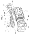
- Fig. 1 illustrates a video camera with a liquid crystal display (LCD) monitor stored in a storage portion.
- LCD liquid crystal display
- Fig. 2 illustrates a video camera with a LCD monitor stored in a storage portion.
- Fig. 3 illustrates a state of a two-axis hinge when the LCD monitor is drawn to an opposite side to a grip portion.
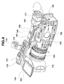
- Fig. 4 illustrates a state in which the LCD monitor is drawn to the opposite side to the grip portion.
- Fig. 5 illustrates a state in which the LCD monitor is drawn to the opposite side to the grip portion.
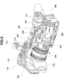
- Fig. 6 illustrates a state in which the LCD monitor is drawn to the opposite side to the grip portion.
- Fig. 7 illustrates a state of a two-axis hinge when the LCD monitor is drawn to a grip portion side.
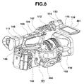
- Fig. 8 illustrates a state in which the LCD monitor is drawn to the grip portion side.
- Fig. 9 illustrates a state in which the LCD monitor is drawn to the grip portion side.
- Fig. 10 illustrates a state in which the LCD monitor is drawn to the grip portion side.
- Fig. 11 illustrates a state viewed from behind the video camera in which the LCD monitor is drawn to the opposite side to the grip portion.
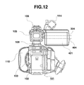
- Fig. 12 illustrates a state viewed from behind the video camera in which the LCD monitor is drawn to the grip portion side.
- Fig. 13 illustrates a state in which the video camera is held by a person.
- Fig. 14 illustrates an exchange operation of the LCD monitor.
- Fig. 15 illustrates an exchange operation of the LCD monitor.
- Fig. 16 illustrates an exchange operation of the LCD monitor.
- Figs. 1 to 16 illustrate a video camera 101 as an imaging apparatus.
- Figs. 1 and 2 illustrate appearances of the video camera 101.
- Figs. 3 to 6 illustrate a state in which a LCD monitor 104 serving as a display monitor is drawn to an opposite side to a grip portion 203.
- Figs. 7 to 10 illustrate a state in which the LCD monitor 104 is drawn to a side of the grip portion 203.
- Fig. 11 illustrates a state in which the LCD monitor 104 is drawn to the opposite side to the grip portion 203 that is viewed from behind the video camera 101.
- Fig. 12 illustrates a state in which the LCD monitor 104 is drawn to the grip portion 203 side that is viewed from behind the video camera 101.
- Fig. 13 illustrates a state in which the video camera 101 is held by a person.
- Figs. 14 to 16 illustrate an exchange operation of the LCD monitor 104.
- the video camera 101 includes a camera main body 102 and a lens unit 103 mounted so as to be projected in front of the camera main body 102. At a leading edge of the lens unit 103, a lens hood 110 for intercepting unnecessary light incident on the lens unit 103 is detachably attached.
- a grip portion 203 to be held by a photographer is integrally provided on the camera main body 102.
- a grip belt is disposed in the grip portion 203. The photographer inserts his/her hand between the grip portion 203 and the grip belt to hold the grip portion 203.
- a handle portion 106 that extends in a forward and backward direction, which is an optical axis direction of the lens unit 103, is integrally provided.
- the handle portion 106 includes a front leg portion 107 vertically provided on a front side of the upper part of the camera main body 102, a rear leg portion 108 vertically provided on a rear side of the upper part of the camera main body 102, and a handle holding portion 109 which connects the front leg portion 107 and the rear leg portion 108.
- an electronic view finder 105 On an upper part of the rear leg portion 108 and a rear end of the handle holding portion 109, an electronic view finder 105 by which the photographer can visually confirms an object is rotatably mounted.
- the electronic view finder 105 is mounted with an eye cup 111.
- the electronic view finder 105 can be rotated roughly 70 degrees upward from the states illustrated in Figs. 1 and 2 .
- a pedestal portion 112 which is continuously formed in the handle holding portion 109 and a projected portion 113 which is continuously formed at the leading edge of the pedestal portion 112 are provided.
- a plurality of operation members for operating the video camera 101 is disposed on the surface of the pedestal portion 112.
- a storage portion for storing the LCD monitor 104 is formed on the back of the pedestal portion 1112. In this state, a display surface 401 of the LCD monitor 104 faces the back of the pedestal portion 112. Thus, the display surface 401 is protected by the pedestal portion 112.
- an external microphone holding portion 114 to hold an external microphone such as a gun microphone is mounted.
- the projected portion 113 is made of a hollow portion which is opened in front, and on the right and left sides. Inside the hollow portion, a microphone (not illustrated) is stored. On the back of the projected portion 113, a two-axis hinge 301 is mounted as a hinge member which rotatably supports the LCD monitor 104 to the handle portion 106. A hinge cover 115 covers the two-axis hinge 301.
- Fig. 3 illustrates a state in which the LCD monitor 104 is drawn from the storage states illustrated in Figs. 1 and 2 to the opposite side to the grip portion 203.
- Fig. 3 illustrates the pedestal portion 112 and the projected portion 113 viewed from the back side thereof. Further, Fig. 3 is in a state in which the hinge cover 115 is removed and the two-axis hinge 301 is exposed.
- the two-axis hinge 301 enables the LCD monitor 104 to rotate around a first rotating shaft 303. Further in a state in Fig. 3 , the two-axis hinge 301 enables the LCD monitor 104 to rotate around a second rotating shaft 304.
- the second rotating shaft 304 is set in a position offset in parallel with a center line in a short side direction of the LCD monitor 104.
- the center line in the short side direction of the LCD monitor 104 and the first rotating shaft 303 are positioned so as to orthogonally intersect. Accordingly, the first rotating shaft 303 and the second rotating shaft 304 are not intersected to have a relationship of a twisted position. An angle to be formed between the first rotating shaft 303 and the second rotating shaft 304 becomes 90 degrees.
- the two-axis hinge 301 is constituted of a fastening portion 305 to be fastened with a screw to the back of the projected portion 113, a first rotation portion 306 to be rotated relative to the fastening portion 305, and a second rotation portion 307 to be rotated relative to the first rotation portion 306.
- a shaft portion 308 is formed in the fastening portion 305.
- a bearing portion to be inserted into the shaft portion 308 is formed in the first rotation portion 306 .
- the center shaft of the shaft portion 308 serves as the first rotating shaft 303.
- a shaft portion 309 is formed in the second rotation portion 307.
- a bearing portion to be inserted into the shaft portion 309 is formed in the first rotation portion 306, a bearing portion to be inserted into the shaft portion 309 is formed in the first rotation portion 306, a bearing portion to be inserted into the shaft portion 309 is formed.
- the center shaft of the shaft portion 309 serves as the second rotating shaft 304.
- first rotation portion 306 is rotated around the first rotating shaft 303 relative to the fastening portion 305 and the second rotation portion 307 is rotated around the second rotating shaft 304 relative to the first rotation portion 306.
- the second rotation portion 307 is fastened with a screw to a monitor case 403 of the LCD monitor 104. Accordingly, one end of the two-axis hinge 301 is secured to the LCD monitor 104 and the other end of the two-axis hinge 301 is secured to the projected portion 113.
- the first rotation portion 306 is configured so as to be rotated up to about 90 degrees in a direction of an arrow Y that is a first direction relative to the fastening portion 305 and also to be rotated up to about 90 degrees in a direction of an arrow Y' that is a second direction which is an opposite direction to the first direction. More specifically, the first rotation portion 306 can be rotated in a range of about 180 degrees relative to the fastening portion 305.
- Fig. 3 illustrates a state in which the LCD monitor 104 is rotated about 90 degrees from the states illustrated in Figs. 1 and 2 in a direction of the arrow Y in Fig. 3 , and is drawn from the pedestal portion 112 to the opposite side to the grip portion 203.
- the second rotation portion 307 is configured so as to be rotated up to about 90 degrees from the state in Fig. 3 in a direction of an arrow X relative to the first rotation portion 306 and also to be rotated up to about 180 degrees in a direction of an arrow X'. More specifically, the second rotation portion 307 can be rotated in a range of about 270 degrees relative to the first rotation portion 306.
- Fig. 4 illustrates a state in which the LCD monitor 104 is drawn from the storage states illustrated in Figs. 1 and 2 to the opposite side to the grip portion 203.
- the first rotation portion 306 is rotated about 90 degrees in the direction of the arrow Y in Fig. 3 relative to the fastening portion 305.
- the video camera 101 is changed into a state in which the display surface 401 of the LCD monitor 104 faces upward and is exposed from the pedestal portion 112. In this state, in low angle shooting, an object can be confirmed by the LCD monitor 104 on the opposite side to the grip portion 203.
- Fig. 4 is in a state in which the hinge cover 115 is attached.
- the LCD monitor 104 is rotated from the state in Fig. 4 around the second rotating shaft 304 so as to turn the display surface 401 to face rearward of the video camera 101.
- the video camera 101 is changed into a state illustrated in Fig. 5 .
- the second rotation portion 307 is rotated about 90 degrees from the state illustrated in Fig. 3 in the direction of the arrow X' in Fig. 3 relative to the first rotation portion 306.
- the display surface 401 of the LCD monitor 104 can further be rotated downward up to 90 degrees from the state illustrated in Fig. 5 around the second rotating shaft 304.
- the display surface 401 of the LCD monitor 104 passes through the state illustrated in Fig. 5 to face downward to the video camera 101. Accordingly, even in high angle shooting, an object can be confirmed by the LCD monitor 104.
- the LCD monitor 104 is rotated around the second rotating shaft 304 so that the display surface 401 faces forward of the video camera 101 from the state in Fig. 4 .
- the video camera 101 is changed into the state illustrated in Fig. 6 .
- the second rotation portion 307 is rotated about 90 degrees from the state illustrated in Fig. 3 in the direction of the arrow X in Fig. 3 relative to the first rotation portion 306.
- Fig. 7 illustrates a state in which the LCD monitor 104 is drawn from the storage states illustrated in Figs. 1 and 2 to the grip portion 203 side. Similarly to Fig. 3 , Fig. 7 also illustrates the pedestal portion 112 and the projected portion 113 viewed from the back side thereof. Fig. 7 is in a state in which the hinge cover 115 is removed and the two-axis hinge 301 is exposed. Fig. 7 is in a state in which the LCD monitor 104 is rotated about 90 degrees from the states illustrated in Figs. 1 and 2 in a direction of an arrow Y' , and drawn from the pedestal portion 112 to the opposite side to the grip portion 203.
- the second rotation portion 307 is configured so as to be rotated up to about 180 degrees from the state in Fig. 7 in a direction of an arrow X' relative to the first rotation portion 306 and also up to about 90 degrees in a direction of an arrow X. More specifically, the second rotation portion 307 can be rotated in a range of about 270 degrees relative to the first rotation portion 306.
- Fig. 8 illustrates a state in which the LCD monitor 104 is drawn from the storage states illustrated in Figs. 1 and 2 to the grip portion 203 side.
- the first rotation portion 306 is rotated about 90 degrees in the direction of the arrow Y' in Fig. 7 relative to the fastening portion 305.
- the video camera 101 is changed into a state in which the display surface 401 of the LCD monitor 104 faces upward and is exposed from the pedestal portion 112. In this state, in low angle shooting, an object can be confirmed by the LCD monitor 104 on the grip portion 203 side.
- the LCD monitor 104 is rotated from the state in Fig. 8 around the second rotating shaft 304 so as to turn the display surface 401 to face rearward of the video camera 101.
- the video camera 101 is changed into a state illustrated in Fig. 9 .
- the second rotation portion 307 is rotated about 90 degrees from the state illustrated in Fig. 7 in the direction of the arrow X in Fig. 7 relative to the first rotation portion 306.
- the second rotating shaft 304 is located in a position offset from the center position of the LCD monitor 104 so as not to block the display surface 401 by the external microphone holding portion 114. Accordingly, the position of the LCD monitor 104 in a height direction in the state in Fig. 9 is made lower than the position of the LCD monitor 104 in a height direction in the state in Fig. 5 .
- Fig. 11 illustrates the video camera 101 viewed from behind when the LCD monitor 104 is in the state in Fig. 5 .
- Fig. 12 illustrates the video camera 101 viewed from behind when the LCD monitor 104 is in the state in Fig. 9 .
- a line 404 indicates the center line of the LCD monitor 104.
- the center line 404 is positioned above the second rotating shaft 304.
- the LCD monitor 104 is positioned so as not to interfere with the operation of an operation ring provided for the lens unit 103.
- the center line 404 is positioned below the second rotating shaft 304.
- the display surface 401 is positioned below the external microphone holding portion 114. Accordingly, in the state in Fig. 5 , the LCD monitor 104 does not interfere with the operation of the operation ring. Further, in the state in Fig. 9 , the external microphone holding portion 114 does not interfere with confirmation of an image displayed on the LCD monitor 104.
- the LCD monitor 104 is rotated around the second rotating shaft 304 from the state in Fig. 8 such that the display surface 401 faces forward of the video camera 101.
- the video camera 101 is changed into the state illustrated in Fig. 10 .
- the second rotation portion 307 is rotated about 90 degrees from the state illustrated in Fig. 7 in the direction of the arrow X' in Fig. 7 relative to the first rotation portion 306.
- the second rotating shaft 304 is offset from the center position of the LCD monitor 104.
- the LCD monitor 104 is positioned so as to overlap with the external microphone holding portion 114.
- the external microphone holding portion 114 is positioned behind the LCD monitor 104, when the display surface 401 faces forward, the microphone holding portion 114 does not block the display surface 401.
- the display surface 401 of the LCD monitor 104 can further be rotated downward up to 90 degrees from the state in Fig. 10 around the second rotating shaft 304.
- the display surface 401 of the LCD monitor 104 passes through the state illustrated in Fig. 10 and faces downward of the video camera 101. Accordingly, even in high angle shooting in a facing state, an object can be confirmed by the LCD monitor 104.
- the first rotation portion 306 is rotated about 90 degrees in the direction of the arrow Y and in the direction of the arrow Y' relative to the fastening portion 305.
- the LCD monitor 104 can be drawn from the storage states illustrated in Figs. 1 and 2 to the side of the grip portion 203 and the opposite side to the grip portion 203.
- the video camera 101 may be changed into the state illustrated in Fig. 5 or Fig. 6 .
- the video camera 101 may be changed into the state illustrated in Fig. 9 or Fig. 10 .
- the direction of the display surface 401 of the LCD monitor 104 can variously be changed corresponding to a shooting situation.
- Fig. 13 illustrates a state in which a photographer holds the video camera 101 which is in the state illustrated in Fig. 5 .
- This type of video camera is larger and heavier than a household video camera.
- the photographer in order to securely hold the camera, as illustrated in Fig. 13 , the photographer holds the video camera with an arm squeezed and an elbow bent.
- the photographer's eye is separated from the display surface 401 of the LCD monitor 104 at a distance D.
- the two-axis hinge 301 is disposed on the back of the projected portion 113 positioned on the leading edge of the handle portion 106.
- the distance D can be made long. Accordingly, even when the video camera 101 is held as illustrated in Fig. 13 , the display surface 401 of the LCD monitor 104 can be placed as far as possible from the eye of the photographer.
- Figs. 14 and 15 illustrate the video camera 101, from which the lens hood 110 and the hinge cover 115 are removed, viewed from the bottom.
- Fig. 16 illustrates the video camera 101, from which the lens hood 110 and the hinge cover 115 are removed, viewed from the side.
- the hinge cover 115 is secured with a screw, so that the hinge cover 115 can be removed from the video camera 101 by removing the screw.
- the fastening portion 305 of the two-axis hinge 301 is disposed to be projected from the leading edge of the lens unit 103.
- the LCD monitor 104 can be removed from the video camera 101 together with the two-axis hinge 301.
- wiring for executing electric connection and a connection component such as a flexible board are inserted. These components can be separated from the video camera 101 by removing a connector.
- a position where the two-axis hinge 301 is fastened on the back of the projected portion 113 is projected more forward than a position at the leading edge of the lens unit 103 which is indicated by a line A-A.
- the screw 1001 with which the fastening portion 305 is fastened can simply be unfastened by a tool such as a driver. Further, a large space is secured below the two-axis hinge 301. Thus, the operation of attachment and detachment of a connector can also be performed simply and securely.
- the two-axis hinge 301 of the LCD monitor 104 is disposed forward in the handle portion 106 disposed at the upper part of the camera main body 102.
- the display surface 401 of the LCD monitor 104 is turned backward, the display surface 401 can be placed away from the rear end of the video camera 101. Accordingly, even if a photographer holds the video camera 101 with the video camera 101 close to his/her face, a distance between the eyes of the photographer and the display surface 401 can be secured. Thus, an object can be easily confirmed.
- the LCD monitor 104 can be rotated not only to the side of the grip portion of the video camera 101 (right side of the imaging apparatus) but also to the opposite side to the grip portion (left side of the imaging apparatus). Accordingly, the photographer can visually confirm the display surface 401 of the LCD monitor 104 with various shooting postures.
- the projected portion 113 of the handle portion 106 to which the two-axis hinge 301 is fixed is located in a position projected farther than the leading edge of the lens unit 103 from which the lens hood 110 is removed.
- An imaging apparatus (101) includes a pedestal portion (112) which is formed further forward than a handle holding portion (109) and configured to store a display monitor (104) with a display surface (401) of the display monitor face thereto, a projected portion (113) formed further forward than the pedestal portion, and a hinge member (301) one part of which is fixed to the display monitor and the other part of which is fixed to the projected portion.
- the display monitor is drawn from the pedestal portion to an opposite side to a grip portion (203) by rotating the display monitor in a first direction around a first rotating shaft of the hinge member.
- the display monitor is drawn from the pedestal portion to a side of the grip portion by rotating the display monitor in a second direction which is an opposite direction to the first direction around a first rotating shaft.
Landscapes
- Engineering & Computer Science (AREA)
- Multimedia (AREA)
- Signal Processing (AREA)
- Studio Devices (AREA)
- Structure And Mechanism Of Cameras (AREA)
- Camera Bodies And Camera Details Or Accessories (AREA)
- Accessories Of Cameras (AREA)
- Endoscopes (AREA)
Abstract
Description
- The present invention relates to an imaging apparatus including a display monitor for displaying an image.
- Recently, an imaging apparatus such as a digital still camera and a video camera, including a display unit configured to display an image during image capture has become widespread.
- Japanese Patent Application Laid-Open No.
2005-210677 - Recently, the display unit has been made large in size. Thus, the display unit is used in order that not only a photographer simply confirms an image which is being captured but also a staff other than the photographer confirms the image.
- However, in the display unit discussed in Japanese Patent Application Laid-Open No.
2005-210677 - According to an aspect of the present invention, there is provided an imaging apparatus as specified in claims 1 to 6.
- According to an exemplary embodiment of the present invention, an image displayed on the display unit of the imaging apparatus can be confirmed from the right side of the imaging apparatus.
- Further features and aspects of the present invention will become apparent from the following detailed description of exemplary embodiments with reference to the attached drawings.
- The accompanying drawings, which are incorporated in and constitute a part of the specification, illustrate exemplary embodiments, features, and aspects of the invention and, together with the description, serve to explain the principles of the invention.
-
Fig. 1 illustrates a video camera with a liquid crystal display (LCD) monitor stored in a storage portion. -
Fig. 2 illustrates a video camera with a LCD monitor stored in a storage portion. -
Fig. 3 illustrates a state of a two-axis hinge when the LCD monitor is drawn to an opposite side to a grip portion. -
Fig. 4 illustrates a state in which the LCD monitor is drawn to the opposite side to the grip portion. -
Fig. 5 illustrates a state in which the LCD monitor is drawn to the opposite side to the grip portion. -
Fig. 6 illustrates a state in which the LCD monitor is drawn to the opposite side to the grip portion. -
Fig. 7 illustrates a state of a two-axis hinge when the LCD monitor is drawn to a grip portion side. -
Fig. 8 illustrates a state in which the LCD monitor is drawn to the grip portion side. -
Fig. 9 illustrates a state in which the LCD monitor is drawn to the grip portion side. -
Fig. 10 illustrates a state in which the LCD monitor is drawn to the grip portion side. -
Fig. 11 illustrates a state viewed from behind the video camera in which the LCD monitor is drawn to the opposite side to the grip portion. -
Fig. 12 illustrates a state viewed from behind the video camera in which the LCD monitor is drawn to the grip portion side. -
Fig. 13 illustrates a state in which the video camera is held by a person. -
Fig. 14 illustrates an exchange operation of the LCD monitor. -
Fig. 15 illustrates an exchange operation of the LCD monitor. -
Fig. 16 illustrates an exchange operation of the LCD monitor. - Various exemplary embodiments, features, and aspects of the invention will be described in detail below with reference to the drawings.
-
Figs. 1 to 16 illustrate avideo camera 101 as an imaging apparatus.Figs. 1 and2 illustrate appearances of thevideo camera 101.Figs. 3 to 6 illustrate a state in which aLCD monitor 104 serving as a display monitor is drawn to an opposite side to agrip portion 203.Figs. 7 to 10 illustrate a state in which theLCD monitor 104 is drawn to a side of thegrip portion 203. -
Fig. 11 illustrates a state in which theLCD monitor 104 is drawn to the opposite side to thegrip portion 203 that is viewed from behind thevideo camera 101.Fig. 12 illustrates a state in which theLCD monitor 104 is drawn to thegrip portion 203 side that is viewed from behind thevideo camera 101.Fig. 13 illustrates a state in which thevideo camera 101 is held by a person.Figs. 14 to 16 illustrate an exchange operation of theLCD monitor 104. - The
video camera 101 includes a cameramain body 102 and alens unit 103 mounted so as to be projected in front of the cameramain body 102. At a leading edge of thelens unit 103, alens hood 110 for intercepting unnecessary light incident on thelens unit 103 is detachably attached. - On a right side of the camera
main body 102, agrip portion 203 to be held by a photographer is integrally provided on the cameramain body 102. In thegrip portion 203, a grip belt is disposed. The photographer inserts his/her hand between thegrip portion 203 and the grip belt to hold thegrip portion 203. - On an upper part of the camera
main body 102, ahandle portion 106 that extends in a forward and backward direction, which is an optical axis direction of thelens unit 103, is integrally provided. Thehandle portion 106 includes afront leg portion 107 vertically provided on a front side of the upper part of the cameramain body 102, arear leg portion 108 vertically provided on a rear side of the upper part of the cameramain body 102, and ahandle holding portion 109 which connects thefront leg portion 107 and therear leg portion 108. On an upper part of therear leg portion 108 and a rear end of thehandle holding portion 109, anelectronic view finder 105 by which the photographer can visually confirms an object is rotatably mounted. Theelectronic view finder 105 is mounted with aneye cup 111. Theelectronic view finder 105 can be rotated roughly 70 degrees upward from the states illustrated inFigs. 1 and2 . - Further, as illustrated in
Figs. 1 and2 , in front of thehandle portion 106, apedestal portion 112 which is continuously formed in thehandle holding portion 109 and a projectedportion 113 which is continuously formed at the leading edge of thepedestal portion 112 are provided. On the surface of thepedestal portion 112, a plurality of operation members for operating thevideo camera 101 is disposed. On the back of thepedestal portion 112, a storage portion for storing theLCD monitor 104 is formed. In this state, adisplay surface 401 of theLCD monitor 104 faces the back of thepedestal portion 112. Thus, thedisplay surface 401 is protected by thepedestal portion 112. - On the right side of the
pedestal portion 112, an externalmicrophone holding portion 114 to hold an external microphone such as a gun microphone is mounted. - The projected
portion 113 is made of a hollow portion which is opened in front, and on the right and left sides. Inside the hollow portion, a microphone (not illustrated) is stored. On the back of the projectedportion 113, a two-axis hinge 301 is mounted as a hinge member which rotatably supports theLCD monitor 104 to thehandle portion 106. Ahinge cover 115 covers the two-axis hinge 301. -
Fig. 3 illustrates a state in which theLCD monitor 104 is drawn from the storage states illustrated inFigs. 1 and2 to the opposite side to thegrip portion 203.Fig. 3 illustrates thepedestal portion 112 and the projectedportion 113 viewed from the back side thereof. Further,Fig. 3 is in a state in which thehinge cover 115 is removed and the two-axis hinge 301 is exposed. - The two-
axis hinge 301 enables theLCD monitor 104 to rotate around a first rotatingshaft 303. Further in a state inFig. 3 , the two-axis hinge 301 enables theLCD monitor 104 to rotate around a second rotatingshaft 304. The second rotatingshaft 304 is set in a position offset in parallel with a center line in a short side direction of theLCD monitor 104. - Further, in the storage state illustrated in
Figs. 1 and2 and in the state illustrated inFig. 3 , the center line in the short side direction of theLCD monitor 104 and the firstrotating shaft 303 are positioned so as to orthogonally intersect. Accordingly, the firstrotating shaft 303 and the secondrotating shaft 304 are not intersected to have a relationship of a twisted position. An angle to be formed between the firstrotating shaft 303 and the secondrotating shaft 304 becomes 90 degrees. - The two-
axis hinge 301 is constituted of afastening portion 305 to be fastened with a screw to the back of the projectedportion 113, afirst rotation portion 306 to be rotated relative to thefastening portion 305, and asecond rotation portion 307 to be rotated relative to thefirst rotation portion 306. - In the
fastening portion 305, ashaft portion 308 is formed. In thefirst rotation portion 306, a bearing portion to be inserted into theshaft portion 308 is formed. The center shaft of theshaft portion 308 serves as the firstrotating shaft 303. In thesecond rotation portion 307, ashaft portion 309 is formed. In thefirst rotation portion 306, a bearing portion to be inserted into theshaft portion 309 is formed. The center shaft of theshaft portion 309 serves as the secondrotating shaft 304. - More specifically, the
first rotation portion 306 is rotated around the firstrotating shaft 303 relative to thefastening portion 305 and thesecond rotation portion 307 is rotated around the secondrotating shaft 304 relative to thefirst rotation portion 306. Thesecond rotation portion 307 is fastened with a screw to amonitor case 403 of theLCD monitor 104. Accordingly, one end of the two-axis hinge 301 is secured to theLCD monitor 104 and the other end of the two-axis hinge 301 is secured to the projectedportion 113. - The
first rotation portion 306 is configured so as to be rotated up to about 90 degrees in a direction of an arrow Y that is a first direction relative to thefastening portion 305 and also to be rotated up to about 90 degrees in a direction of an arrow Y' that is a second direction which is an opposite direction to the first direction. More specifically, thefirst rotation portion 306 can be rotated in a range of about 180 degrees relative to thefastening portion 305.Fig. 3 illustrates a state in which theLCD monitor 104 is rotated about 90 degrees from the states illustrated inFigs. 1 and2 in a direction of the arrow Y inFig. 3 , and is drawn from thepedestal portion 112 to the opposite side to thegrip portion 203. - The
second rotation portion 307 is configured so as to be rotated up to about 90 degrees from the state inFig. 3 in a direction of an arrow X relative to thefirst rotation portion 306 and also to be rotated up to about 180 degrees in a direction of an arrow X'. More specifically, thesecond rotation portion 307 can be rotated in a range of about 270 degrees relative to thefirst rotation portion 306. - Similarly to
Fig. 3 ,Fig. 4 illustrates a state in which theLCD monitor 104 is drawn from the storage states illustrated inFigs. 1 and2 to the opposite side to thegrip portion 203. At this time, inside the two-axis hinge 301, thefirst rotation portion 306 is rotated about 90 degrees in the direction of the arrow Y inFig. 3 relative to thefastening portion 305. Accordingly, as illustrated inFig. 4 , thevideo camera 101 is changed into a state in which thedisplay surface 401 of theLCD monitor 104 faces upward and is exposed from thepedestal portion 112. In this state, in low angle shooting, an object can be confirmed by theLCD monitor 104 on the opposite side to thegrip portion 203.Fig. 4 is in a state in which thehinge cover 115 is attached. - The
LCD monitor 104 is rotated from the state inFig. 4 around the secondrotating shaft 304 so as to turn thedisplay surface 401 to face rearward of thevideo camera 101. Thus, thevideo camera 101 is changed into a state illustrated inFig. 5 . At this time, inside the two-axis hinge 301, thesecond rotation portion 307 is rotated about 90 degrees from the state illustrated inFig. 3 in the direction of the arrow X' inFig. 3 relative to thefirst rotation portion 306. - Further, the
display surface 401 of theLCD monitor 104 can further be rotated downward up to 90 degrees from the state illustrated inFig. 5 around the secondrotating shaft 304. In the state in which theLCD monitor 104 is drawn to the opposite side to thegrip portion 203, by rotating theLCD monitor 104 around the secondrotating shaft 304, thedisplay surface 401 of the LCD monitor 104 passes through the state illustrated inFig. 5 to face downward to thevideo camera 101. Accordingly, even in high angle shooting, an object can be confirmed by theLCD monitor 104. - Further, the
LCD monitor 104 is rotated around the secondrotating shaft 304 so that thedisplay surface 401 faces forward of thevideo camera 101 from the state inFig. 4 . Thus, thevideo camera 101 is changed into the state illustrated inFig. 6 . At this time, inside the two-axis hinge 301, thesecond rotation portion 307 is rotated about 90 degrees from the state illustrated inFig. 3 in the direction of the arrow X inFig. 3 relative to thefirst rotation portion 306. -
Fig. 7 illustrates a state in which theLCD monitor 104 is drawn from the storage states illustrated inFigs. 1 and2 to thegrip portion 203 side. Similarly toFig. 3 ,Fig. 7 also illustrates thepedestal portion 112 and the projectedportion 113 viewed from the back side thereof.Fig. 7 is in a state in which thehinge cover 115 is removed and the two-axis hinge 301 is exposed.Fig. 7 is in a state in which theLCD monitor 104 is rotated about 90 degrees from the states illustrated inFigs. 1 and2 in a direction of an arrow Y' , and drawn from thepedestal portion 112 to the opposite side to thegrip portion 203. - The
second rotation portion 307 is configured so as to be rotated up to about 180 degrees from the state inFig. 7 in a direction of an arrow X' relative to thefirst rotation portion 306 and also up to about 90 degrees in a direction of an arrow X. More specifically, thesecond rotation portion 307 can be rotated in a range of about 270 degrees relative to thefirst rotation portion 306. -
Fig. 8 illustrates a state in which theLCD monitor 104 is drawn from the storage states illustrated inFigs. 1 and2 to thegrip portion 203 side. At this time, inside the two-axis hinge 301, thefirst rotation portion 306 is rotated about 90 degrees in the direction of the arrow Y' inFig. 7 relative to thefastening portion 305. Accordingly, as illustrated inFig. 8 , thevideo camera 101 is changed into a state in which thedisplay surface 401 of theLCD monitor 104 faces upward and is exposed from thepedestal portion 112. In this state, in low angle shooting, an object can be confirmed by theLCD monitor 104 on thegrip portion 203 side. - The
LCD monitor 104 is rotated from the state inFig. 8 around the secondrotating shaft 304 so as to turn thedisplay surface 401 to face rearward of thevideo camera 101. Thus, thevideo camera 101 is changed into a state illustrated inFig. 9 . At this time, inside the two-axis hinge 301, thesecond rotation portion 307 is rotated about 90 degrees from the state illustrated inFig. 7 in the direction of the arrow X inFig. 7 relative to thefirst rotation portion 306. - When the
LCD monitor 104 is changed into the state inFig. 9 , the secondrotating shaft 304 is located in a position offset from the center position of theLCD monitor 104 so as not to block thedisplay surface 401 by the externalmicrophone holding portion 114. Accordingly, the position of theLCD monitor 104 in a height direction in the state inFig. 9 is made lower than the position of theLCD monitor 104 in a height direction in the state inFig. 5 . -
Fig. 11 illustrates thevideo camera 101 viewed from behind when theLCD monitor 104 is in the state inFig. 5 .Fig. 12 illustrates thevideo camera 101 viewed from behind when theLCD monitor 104 is in the state inFig. 9 . InFigs. 11 and12 , aline 404 indicates the center line of theLCD monitor 104. - As illustrated in
Fig. 11 , in the state inFig. 5 , thecenter line 404 is positioned above the secondrotating shaft 304. Thus, theLCD monitor 104 is positioned so as not to interfere with the operation of an operation ring provided for thelens unit 103. On the other hand, as illustrated inFig. 12 , in the state inFig. 9 , thecenter line 404 is positioned below the secondrotating shaft 304. Thus, thedisplay surface 401 is positioned below the externalmicrophone holding portion 114. Accordingly, in the state inFig. 5 , theLCD monitor 104 does not interfere with the operation of the operation ring. Further, in the state inFig. 9 , the externalmicrophone holding portion 114 does not interfere with confirmation of an image displayed on theLCD monitor 104. - Further, the
LCD monitor 104 is rotated around the secondrotating shaft 304 from the state inFig. 8 such that thedisplay surface 401 faces forward of thevideo camera 101. Thus, thevideo camera 101 is changed into the state illustrated inFig. 10 . At this time, inside the two-axis hinge 301, thesecond rotation portion 307 is rotated about 90 degrees from the state illustrated inFig. 7 in the direction of the arrow X' inFig. 7 relative to thefirst rotation portion 306. The secondrotating shaft 304 is offset from the center position of theLCD monitor 104. Thus, in the state inFig. 10 , theLCD monitor 104 is positioned so as to overlap with the externalmicrophone holding portion 114. However, since the externalmicrophone holding portion 114 is positioned behind theLCD monitor 104, when thedisplay surface 401 faces forward, themicrophone holding portion 114 does not block thedisplay surface 401. - The
display surface 401 of theLCD monitor 104 can further be rotated downward up to 90 degrees from the state inFig. 10 around the secondrotating shaft 304. When theLCD monitor 104 is drawn to thegrip portion 203 side, by rotating theLCD monitor 104 around the secondrotating shaft 304, thedisplay surface 401 of the LCD monitor 104 passes through the state illustrated inFig. 10 and faces downward of thevideo camera 101. Accordingly, even in high angle shooting in a facing state, an object can be confirmed by theLCD monitor 104. - As described above, in the
video camera 101 according to the present exemplary embodiment, thefirst rotation portion 306 is rotated about 90 degrees in the direction of the arrow Y and in the direction of the arrow Y' relative to thefastening portion 305. Thus, theLCD monitor 104 can be drawn from the storage states illustrated inFigs. 1 and2 to the side of thegrip portion 203 and the opposite side to thegrip portion 203. - Accordingly, when a captured image is monitored from the opposite side to the
grip portion 203, thevideo camera 101 may be changed into the state illustrated inFig. 5 orFig. 6 . When the captured image is monitored from the side of thegrip portion 203, thevideo camera 101 may be changed into the state illustrated inFig. 9 orFig. 10 . - Further, the
display surface 401 of theLCD monitor 104 can further be rotated downward up to 90 degrees from the state illustrated inFig. 5 around the secondrotating shaft 304. Furthermore, thedisplay surface 401 of theLCD monitor 104 can further be rotated downward up to 90 degrees from the state illustrated inFig. 10 around the secondrotating shaft 304. - Accordingly, the direction of the
display surface 401 of theLCD monitor 104 can variously be changed corresponding to a shooting situation. -
Fig. 13 illustrates a state in which a photographer holds thevideo camera 101 which is in the state illustrated inFig. 5 . This type of video camera is larger and heavier than a household video camera. Thus, in order to securely hold the camera, as illustrated inFig. 13 , the photographer holds the video camera with an arm squeezed and an elbow bent. - In
Fig. 13 , the photographer's eye is separated from thedisplay surface 401 of theLCD monitor 104 at a distance D. In thevideo camera 101 according to the present exemplary embodiment, the two-axis hinge 301 is disposed on the back of the projectedportion 113 positioned on the leading edge of thehandle portion 106. Thus, when thedisplay surface 401 of theLCD monitor 104 is turned backward, the distance D can be made long. Accordingly, even when thevideo camera 101 is held as illustrated inFig. 13 , thedisplay surface 401 of theLCD monitor 104 can be placed as far as possible from the eye of the photographer. - Next, an exchange operation of the
LCD monitor 104 will be described. -
Figs. 14 and15 illustrate thevideo camera 101, from which thelens hood 110 and thehinge cover 115 are removed, viewed from the bottom.Fig. 16 illustrates thevideo camera 101, from which thelens hood 110 and thehinge cover 115 are removed, viewed from the side. Thehinge cover 115 is secured with a screw, so that thehinge cover 115 can be removed from thevideo camera 101 by removing the screw. - As illustrated in
Figs. 14 to 16 , thefastening portion 305 of the two-axis hinge 301 is disposed to be projected from the leading edge of thelens unit 103. By unfastening ascrew 1001 by which thefastening portion 305 is fastened on the back of the projectedportion 113, theLCD monitor 104 can be removed from thevideo camera 101 together with the two-axis hinge 301. Further, into the two-axis hinge 301, wiring for executing electric connection and a connection component (not illustrated) such as a flexible board are inserted. These components can be separated from thevideo camera 101 by removing a connector. - As illustrated in
Fig. 16 , a position where the two-axis hinge 301 is fastened on the back of the projectedportion 113 is projected more forward than a position at the leading edge of thelens unit 103 which is indicated by a line A-A. Thus, thescrew 1001 with which thefastening portion 305 is fastened can simply be unfastened by a tool such as a driver. Further, a large space is secured below the two-axis hinge 301. Thus, the operation of attachment and detachment of a connector can also be performed simply and securely. - As described above, according to the exemplary embodiment of the present invention, the two-
axis hinge 301 of theLCD monitor 104 is disposed forward in thehandle portion 106 disposed at the upper part of the cameramain body 102. Thus, when thedisplay surface 401 of theLCD monitor 104 is turned backward, thedisplay surface 401 can be placed away from the rear end of thevideo camera 101. Accordingly, even if a photographer holds thevideo camera 101 with thevideo camera 101 close to his/her face, a distance between the eyes of the photographer and thedisplay surface 401 can be secured. Thus, an object can be easily confirmed. - Further, it is configured that the
LCD monitor 104 can be rotated not only to the side of the grip portion of the video camera 101 (right side of the imaging apparatus) but also to the opposite side to the grip portion (left side of the imaging apparatus). Accordingly, the photographer can visually confirm thedisplay surface 401 of theLCD monitor 104 with various shooting postures. - Furthermore, the projected
portion 113 of thehandle portion 106 to which the two-axis hinge 301 is fixed is located in a position projected farther than the leading edge of thelens unit 103 from which thelens hood 110 is removed. Thus, when a screw that fastens thefastening portion 305 of the two-axis hinge 301 and the projectedportion 113 is unfastened, a sufficient space can be secured below the two-axis hinge 301 and thelens unit 103 does not obstruct the operation. - While the present invention has been described with reference to exemplary embodiments, it is to be understood that the invention is not limited to the disclosed exemplary embodiments. The scope of the following claims is to be accorded the broadest interpretation so as to encompass all modifications, equivalent structures, and functions.
An imaging apparatus (101) includes a pedestal portion (112) which is formed further forward than a handle holding portion (109) and configured to store a display monitor (104) with a display surface (401) of the display monitor face thereto, a projected portion (113) formed further forward than the pedestal portion, and a hinge member (301) one part of which is fixed to the display monitor and the other part of which is fixed to the projected portion. The display monitor is drawn from the pedestal portion to an opposite side to a grip portion (203) by rotating the display monitor in a first direction around a first rotating shaft of the hinge member. The display monitor is drawn from the pedestal portion to a side of the grip portion by rotating the display monitor in a second direction which is an opposite direction to the first direction around a first rotating shaft.
Claims (6)
- An imaging apparatus (101) including a display monitor (104) for displaying an image, the imaging apparatus comprising:a grip portion (203) formed on a right side of the imaging apparatus;a front leg portion (107) formed on a front side upper part of the imaging apparatus;a rear leg portion (108) formed on a rear side upper part of the imaging apparatus;a handle holding portion (109) configured to connect the front leg portion and the rear leg portion;a pedestal portion (112) which is formed further forward than the handle holding portion and configured to store the display monitor with a display surface (401) of the display monitor face thereto;a projected portion (113) formed further forward than the pedestal portion; anda hinge member (301) one part of which is fixed to the display monitor and the other part of which is fixed to the projected portion,wherein the display monitor is drawn from the pedestal portion to an opposite side to the grip portion by rotating the display monitor in a first direction around a first rotating shaft of the hinge member, andwherein the display monitor is drawn from the pedestal portion to a side of the grip portion by rotating the display monitor in a second direction which is an opposite direction to the first direction around a first rotating shaft.
- The imaging apparatus according to claim 1, further comprising a lens unit (103), wherein the hinge member is fixed to the projected portion further forward than a leading edge of the lens unit.
- The imaging apparatus according to claim 1, wherein the hinge member is a two-axis hinge capable of rotating the display monitor by the second rotating shaft that forms an angle of 90 degrees with the first rotating shaft, and the display surface of the display monitor passes through a state in which the display surface faces rearward of the imaging apparatus and becomes a state facing downward of the imaging apparatus by rotating the display monitor around the second rotating shaft if the display monitor is drawn from the pedestal portion to the opposite side to the grip portion.
- The imaging apparatus according to claim 3, wherein the hinge member is a two-axis hinge capable of rotating the display monitor by the second rotating shaft orthogonal to the first rotating shaft, and the second rotating shaft is set in a position offset from a center line in a short side direction of the display monitor.
- The imaging apparatus according to claim 4, wherein the second rotating shaft is set in a position offset from the center line in the short side direction of the display monitor such that the center line in the short side direction of the display monitor is located in a position higher than the second rotating shaft if the display monitor is drawn from the pedestal portion to the opposite side to the grip portion, and is rotated around the second rotating shaft so as to turn the display surface to face rearward of the imaging apparatus.
- The imaging apparatus according to claim 1, wherein a position of the first rotating shaft is set such that the first rotating shaft orthogonally intersects the center line of the display monitor in the short side direction in a state where the display monitor is stored in the pedestal portion.
Priority Applications (1)
| Application Number | Priority Date | Filing Date | Title |
|---|---|---|---|
| EP15175839.8A EP2961154B1 (en) | 2009-10-29 | 2010-10-06 | Imaging apparatus |
Applications Claiming Priority (1)
| Application Number | Priority Date | Filing Date | Title |
|---|---|---|---|
| JP2009249092A JP5398476B2 (en) | 2009-10-29 | 2009-10-29 | Imaging device |
Related Child Applications (2)
| Application Number | Title | Priority Date | Filing Date |
|---|---|---|---|
| EP15175839.8A Division EP2961154B1 (en) | 2009-10-29 | 2010-10-06 | Imaging apparatus |
| EP15175839.8A Division-Into EP2961154B1 (en) | 2009-10-29 | 2010-10-06 | Imaging apparatus |
Publications (3)
| Publication Number | Publication Date |
|---|---|
| EP2326077A2 true EP2326077A2 (en) | 2011-05-25 |
| EP2326077A3 EP2326077A3 (en) | 2011-12-07 |
| EP2326077B1 EP2326077B1 (en) | 2015-08-12 |
Family
ID=43486397
Family Applications (2)
| Application Number | Title | Priority Date | Filing Date |
|---|---|---|---|
| EP10186691.1A Not-in-force EP2326077B1 (en) | 2009-10-29 | 2010-10-06 | Imaging apparatus |
| EP15175839.8A Active EP2961154B1 (en) | 2009-10-29 | 2010-10-06 | Imaging apparatus |
Family Applications After (1)
| Application Number | Title | Priority Date | Filing Date |
|---|---|---|---|
| EP15175839.8A Active EP2961154B1 (en) | 2009-10-29 | 2010-10-06 | Imaging apparatus |
Country Status (5)
| Country | Link |
|---|---|
| US (1) | US8390716B2 (en) |
| EP (2) | EP2326077B1 (en) |
| JP (1) | JP5398476B2 (en) |
| KR (1) | KR101271039B1 (en) |
| CN (1) | CN102055891B (en) |
Cited By (1)
| Publication number | Priority date | Publication date | Assignee | Title |
|---|---|---|---|---|
| EP2961154A1 (en) | 2009-10-29 | 2015-12-30 | Canon Kabushiki Kaisha | Imaging apparatus |
Families Citing this family (5)
| Publication number | Priority date | Publication date | Assignee | Title |
|---|---|---|---|---|
| JP5943580B2 (en) * | 2011-10-31 | 2016-07-05 | キヤノン株式会社 | Display unit and imaging apparatus including display unit |
| EP2972580B1 (en) * | 2013-03-15 | 2018-05-09 | Launi, Enrique | Holder for a mobile device to capture images |
| US9826134B2 (en) * | 2015-03-27 | 2017-11-21 | Panasonic Intellectual Property Management Co., Ltd. | Imaging apparatus having a microphone and directivity control |
| JP6980576B2 (en) * | 2018-03-19 | 2021-12-15 | キヤノン株式会社 | Imaging device |
| US11274787B2 (en) | 2019-05-30 | 2022-03-15 | Alcon Inc. | Stopping element for limiting rotational range of a rotating part |
Citations (1)
| Publication number | Priority date | Publication date | Assignee | Title |
|---|---|---|---|---|
| JP2005210677A (en) | 2003-10-02 | 2005-08-04 | Sony Corp | Imaging device |
Family Cites Families (11)
| Publication number | Priority date | Publication date | Assignee | Title |
|---|---|---|---|---|
| JP2858344B2 (en) * | 1990-03-15 | 1999-02-17 | 松下電器産業株式会社 | Video camera equipment |
| JPH0622186A (en) * | 1992-07-06 | 1994-01-28 | Matsushita Electric Ind Co Ltd | Video camera compatible with left hander and right hander |
| JP2001358973A (en) * | 2000-06-13 | 2001-12-26 | Sony Corp | Video camera |
| SE524024C2 (en) * | 2002-03-01 | 2004-06-15 | Flir Systems Ab | IR camera |
| JP4151003B2 (en) | 2002-09-13 | 2008-09-17 | 日本ビクター株式会社 | Camera integrated recording and playback device |
| KR100806390B1 (en) * | 2003-08-18 | 2008-02-27 | 삼성전자주식회사 | Video recording device |
| JP2005101714A (en) * | 2003-09-22 | 2005-04-14 | Fuji Photo Film Co Ltd | Photographic equipment |
| JP2008020646A (en) * | 2006-07-12 | 2008-01-31 | Sony Corp | Imaging device |
| JP4432982B2 (en) | 2007-02-16 | 2010-03-17 | ソニー株式会社 | Viewfinder and imaging device |
| JP4293256B2 (en) * | 2007-03-27 | 2009-07-08 | ソニー株式会社 | Imaging device |
| JP5398476B2 (en) | 2009-10-29 | 2014-01-29 | キヤノン株式会社 | Imaging device |
-
2009
- 2009-10-29 JP JP2009249092A patent/JP5398476B2/en not_active Expired - Fee Related
-
2010
- 2010-10-06 EP EP10186691.1A patent/EP2326077B1/en not_active Not-in-force
- 2010-10-06 EP EP15175839.8A patent/EP2961154B1/en active Active
- 2010-10-25 US US12/911,568 patent/US8390716B2/en not_active Expired - Fee Related
- 2010-10-28 CN CN2010105284800A patent/CN102055891B/en not_active Expired - Fee Related
- 2010-10-29 KR KR1020100106450A patent/KR101271039B1/en not_active Expired - Fee Related
Patent Citations (1)
| Publication number | Priority date | Publication date | Assignee | Title |
|---|---|---|---|---|
| JP2005210677A (en) | 2003-10-02 | 2005-08-04 | Sony Corp | Imaging device |
Cited By (1)
| Publication number | Priority date | Publication date | Assignee | Title |
|---|---|---|---|---|
| EP2961154A1 (en) | 2009-10-29 | 2015-12-30 | Canon Kabushiki Kaisha | Imaging apparatus |
Also Published As
| Publication number | Publication date |
|---|---|
| EP2961154A1 (en) | 2015-12-30 |
| JP5398476B2 (en) | 2014-01-29 |
| CN102055891A (en) | 2011-05-11 |
| EP2326077A3 (en) | 2011-12-07 |
| KR101271039B1 (en) | 2013-06-04 |
| CN102055891B (en) | 2013-06-26 |
| JP2011097347A (en) | 2011-05-12 |
| US20110102659A1 (en) | 2011-05-05 |
| EP2961154B1 (en) | 2019-12-11 |
| EP2326077B1 (en) | 2015-08-12 |
| US8390716B2 (en) | 2013-03-05 |
| KR20110047156A (en) | 2011-05-06 |
Similar Documents
| Publication | Publication Date | Title |
|---|---|---|
| US8390716B2 (en) | Imaging apparatus having a display monitor | |
| US5659361A (en) | Tiltable, rotatable and detachable LCD viewfinder | |
| US8373795B2 (en) | Camera body and imaging device to which a lens unit configured to form an optical image of a subject can be mounted | |
| CN109952533A (en) | Adapter for electronic viewfinder, camera and electronic viewfinder | |
| CN206060945U (en) | A kind of 360 degree of panoramic shooting modules and electronic equipment | |
| US20050174480A1 (en) | Digital camera | |
| JP2015186084A (en) | Imaging device | |
| JP5637835B2 (en) | Electronics | |
| JPH11331669A (en) | Video camera | |
| JP5040771B2 (en) | Imaging device | |
| JP4780913B2 (en) | Video camera | |
| JP4509234B2 (en) | Electronic camera | |
| JP5404327B2 (en) | Imaging device | |
| US11910075B2 (en) | Imaging apparatus | |
| JP2003315891A (en) | camera | |
| CN220122972U (en) | Image pickup apparatus | |
| JP4766834B2 (en) | camera | |
| JP2011124902A (en) | Imaging apparatus | |
| JP5409274B2 (en) | Imaging device | |
| JP5127367B2 (en) | Camera equipment with a display | |
| CN103676412A (en) | Grip member and image pickup device | |
| JP2009261015A (en) | Video camera | |
| JPH1169213A (en) | Camera with monitor device | |
| JP2009199000A (en) | Imaging apparatus | |
| JP2017028472A (en) | Imaging device |
Legal Events
| Date | Code | Title | Description |
|---|---|---|---|
| PUAI | Public reference made under article 153(3) epc to a published international application that has entered the european phase |
Free format text: ORIGINAL CODE: 0009012 |
|
| AK | Designated contracting states |
Kind code of ref document: A2 Designated state(s): AL AT BE BG CH CY CZ DE DK EE ES FI FR GB GR HR HU IE IS IT LI LT LU LV MC MK MT NL NO PL PT RO RS SE SI SK SM TR |
|
| AX | Request for extension of the european patent |
Extension state: BA ME |
|
| PUAL | Search report despatched |
Free format text: ORIGINAL CODE: 0009013 |
|
| AK | Designated contracting states |
Kind code of ref document: A3 Designated state(s): AL AT BE BG CH CY CZ DE DK EE ES FI FR GB GR HR HU IE IS IT LI LT LU LV MC MK MT NL NO PL PT RO RS SE SI SK SM TR |
|
| AX | Request for extension of the european patent |
Extension state: BA ME |
|
| RIC1 | Information provided on ipc code assigned before grant |
Ipc: H04N 5/225 20060101AFI20111103BHEP |
|
| 17P | Request for examination filed |
Effective date: 20120608 |
|
| 17Q | First examination report despatched |
Effective date: 20130724 |
|
| GRAP | Despatch of communication of intention to grant a patent |
Free format text: ORIGINAL CODE: EPIDOSNIGR1 |
|
| INTG | Intention to grant announced |
Effective date: 20150304 |
|
| GRAS | Grant fee paid |
Free format text: ORIGINAL CODE: EPIDOSNIGR3 |
|
| GRAA | (expected) grant |
Free format text: ORIGINAL CODE: 0009210 |
|
| AK | Designated contracting states |
Kind code of ref document: B1 Designated state(s): AL AT BE BG CH CY CZ DE DK EE ES FI FR GB GR HR HU IE IS IT LI LT LU LV MC MK MT NL NO PL PT RO RS SE SI SK SM TR |
|
| REG | Reference to a national code |
Ref country code: GB Ref legal event code: FG4D |
|
| REG | Reference to a national code |
Ref country code: CH Ref legal event code: EP |
|
| REG | Reference to a national code |
Ref country code: AT Ref legal event code: REF Ref document number: 743027 Country of ref document: AT Kind code of ref document: T Effective date: 20150815 |
|
| REG | Reference to a national code |
Ref country code: IE Ref legal event code: FG4D |
|
| REG | Reference to a national code |
Ref country code: DE Ref legal event code: R096 Ref document number: 602010026541 Country of ref document: DE |
|
| REG | Reference to a national code |
Ref country code: LT Ref legal event code: MG4D |
|
| REG | Reference to a national code |
Ref country code: AT Ref legal event code: MK05 Ref document number: 743027 Country of ref document: AT Kind code of ref document: T Effective date: 20150812 |
|
| REG | Reference to a national code |
Ref country code: NL Ref legal event code: MP Effective date: 20150812 |
|
| PG25 | Lapsed in a contracting state [announced via postgrant information from national office to epo] |
Ref country code: NO Free format text: LAPSE BECAUSE OF FAILURE TO SUBMIT A TRANSLATION OF THE DESCRIPTION OR TO PAY THE FEE WITHIN THE PRESCRIBED TIME-LIMIT Effective date: 20151112 Ref country code: LT Free format text: LAPSE BECAUSE OF FAILURE TO SUBMIT A TRANSLATION OF THE DESCRIPTION OR TO PAY THE FEE WITHIN THE PRESCRIBED TIME-LIMIT Effective date: 20150812 Ref country code: LV Free format text: LAPSE BECAUSE OF FAILURE TO SUBMIT A TRANSLATION OF THE DESCRIPTION OR TO PAY THE FEE WITHIN THE PRESCRIBED TIME-LIMIT Effective date: 20150812 Ref country code: FI Free format text: LAPSE BECAUSE OF FAILURE TO SUBMIT A TRANSLATION OF THE DESCRIPTION OR TO PAY THE FEE WITHIN THE PRESCRIBED TIME-LIMIT Effective date: 20150812 Ref country code: GR Free format text: LAPSE BECAUSE OF FAILURE TO SUBMIT A TRANSLATION OF THE DESCRIPTION OR TO PAY THE FEE WITHIN THE PRESCRIBED TIME-LIMIT Effective date: 20151113 |
|
| PG25 | Lapsed in a contracting state [announced via postgrant information from national office to epo] |
Ref country code: AT Free format text: LAPSE BECAUSE OF FAILURE TO SUBMIT A TRANSLATION OF THE DESCRIPTION OR TO PAY THE FEE WITHIN THE PRESCRIBED TIME-LIMIT Effective date: 20150812 Ref country code: IS Free format text: LAPSE BECAUSE OF FAILURE TO SUBMIT A TRANSLATION OF THE DESCRIPTION OR TO PAY THE FEE WITHIN THE PRESCRIBED TIME-LIMIT Effective date: 20151212 Ref country code: SE Free format text: LAPSE BECAUSE OF FAILURE TO SUBMIT A TRANSLATION OF THE DESCRIPTION OR TO PAY THE FEE WITHIN THE PRESCRIBED TIME-LIMIT Effective date: 20150812 Ref country code: RS Free format text: LAPSE BECAUSE OF FAILURE TO SUBMIT A TRANSLATION OF THE DESCRIPTION OR TO PAY THE FEE WITHIN THE PRESCRIBED TIME-LIMIT Effective date: 20150812 Ref country code: PL Free format text: LAPSE BECAUSE OF FAILURE TO SUBMIT A TRANSLATION OF THE DESCRIPTION OR TO PAY THE FEE WITHIN THE PRESCRIBED TIME-LIMIT Effective date: 20150812 Ref country code: PT Free format text: LAPSE BECAUSE OF FAILURE TO SUBMIT A TRANSLATION OF THE DESCRIPTION OR TO PAY THE FEE WITHIN THE PRESCRIBED TIME-LIMIT Effective date: 20151214 Ref country code: HR Free format text: LAPSE BECAUSE OF FAILURE TO SUBMIT A TRANSLATION OF THE DESCRIPTION OR TO PAY THE FEE WITHIN THE PRESCRIBED TIME-LIMIT Effective date: 20150812 Ref country code: ES Free format text: LAPSE BECAUSE OF FAILURE TO SUBMIT A TRANSLATION OF THE DESCRIPTION OR TO PAY THE FEE WITHIN THE PRESCRIBED TIME-LIMIT Effective date: 20150812 |
|
| PG25 | Lapsed in a contracting state [announced via postgrant information from national office to epo] |
Ref country code: NL Free format text: LAPSE BECAUSE OF FAILURE TO SUBMIT A TRANSLATION OF THE DESCRIPTION OR TO PAY THE FEE WITHIN THE PRESCRIBED TIME-LIMIT Effective date: 20150812 |
|
| PG25 | Lapsed in a contracting state [announced via postgrant information from national office to epo] |
Ref country code: SK Free format text: LAPSE BECAUSE OF FAILURE TO SUBMIT A TRANSLATION OF THE DESCRIPTION OR TO PAY THE FEE WITHIN THE PRESCRIBED TIME-LIMIT Effective date: 20150812 Ref country code: CZ Free format text: LAPSE BECAUSE OF FAILURE TO SUBMIT A TRANSLATION OF THE DESCRIPTION OR TO PAY THE FEE WITHIN THE PRESCRIBED TIME-LIMIT Effective date: 20150812 Ref country code: EE Free format text: LAPSE BECAUSE OF FAILURE TO SUBMIT A TRANSLATION OF THE DESCRIPTION OR TO PAY THE FEE WITHIN THE PRESCRIBED TIME-LIMIT Effective date: 20150812 Ref country code: IT Free format text: LAPSE BECAUSE OF FAILURE TO SUBMIT A TRANSLATION OF THE DESCRIPTION OR TO PAY THE FEE WITHIN THE PRESCRIBED TIME-LIMIT Effective date: 20150812 Ref country code: DK Free format text: LAPSE BECAUSE OF FAILURE TO SUBMIT A TRANSLATION OF THE DESCRIPTION OR TO PAY THE FEE WITHIN THE PRESCRIBED TIME-LIMIT Effective date: 20150812 |
|
| REG | Reference to a national code |
Ref country code: DE Ref legal event code: R097 Ref document number: 602010026541 Country of ref document: DE |
|
| PG25 | Lapsed in a contracting state [announced via postgrant information from national office to epo] |
Ref country code: RO Free format text: LAPSE BECAUSE OF FAILURE TO SUBMIT A TRANSLATION OF THE DESCRIPTION OR TO PAY THE FEE WITHIN THE PRESCRIBED TIME-LIMIT Effective date: 20150812 Ref country code: LU Free format text: LAPSE BECAUSE OF FAILURE TO SUBMIT A TRANSLATION OF THE DESCRIPTION OR TO PAY THE FEE WITHIN THE PRESCRIBED TIME-LIMIT Effective date: 20151006 |
|
| REG | Reference to a national code |
Ref country code: CH Ref legal event code: PL |
|
| PLBE | No opposition filed within time limit |
Free format text: ORIGINAL CODE: 0009261 |
|
| STAA | Information on the status of an ep patent application or granted ep patent |
Free format text: STATUS: NO OPPOSITION FILED WITHIN TIME LIMIT |
|
| PG25 | Lapsed in a contracting state [announced via postgrant information from national office to epo] |
Ref country code: MC Free format text: LAPSE BECAUSE OF FAILURE TO SUBMIT A TRANSLATION OF THE DESCRIPTION OR TO PAY THE FEE WITHIN THE PRESCRIBED TIME-LIMIT Effective date: 20150812 |
|
| 26N | No opposition filed |
Effective date: 20160513 |
|
| GBPC | Gb: european patent ceased through non-payment of renewal fee |
Effective date: 20151112 |
|
| REG | Reference to a national code |
Ref country code: IE Ref legal event code: MM4A |
|
| PG25 | Lapsed in a contracting state [announced via postgrant information from national office to epo] |
Ref country code: CH Free format text: LAPSE BECAUSE OF NON-PAYMENT OF DUE FEES Effective date: 20151031 Ref country code: LI Free format text: LAPSE BECAUSE OF NON-PAYMENT OF DUE FEES Effective date: 20151031 |
|
| REG | Reference to a national code |
Ref country code: FR Ref legal event code: ST Effective date: 20160630 |
|
| PG25 | Lapsed in a contracting state [announced via postgrant information from national office to epo] |
Ref country code: FR Free format text: LAPSE BECAUSE OF NON-PAYMENT OF DUE FEES Effective date: 20151102 Ref country code: SI Free format text: LAPSE BECAUSE OF FAILURE TO SUBMIT A TRANSLATION OF THE DESCRIPTION OR TO PAY THE FEE WITHIN THE PRESCRIBED TIME-LIMIT Effective date: 20150812 |
|
| PG25 | Lapsed in a contracting state [announced via postgrant information from national office to epo] |
Ref country code: GB Free format text: LAPSE BECAUSE OF NON-PAYMENT OF DUE FEES Effective date: 20151112 Ref country code: IE Free format text: LAPSE BECAUSE OF NON-PAYMENT OF DUE FEES Effective date: 20151006 |
|
| PG25 | Lapsed in a contracting state [announced via postgrant information from national office to epo] |
Ref country code: BE Free format text: LAPSE BECAUSE OF FAILURE TO SUBMIT A TRANSLATION OF THE DESCRIPTION OR TO PAY THE FEE WITHIN THE PRESCRIBED TIME-LIMIT Effective date: 20150812 |
|
| PG25 | Lapsed in a contracting state [announced via postgrant information from national office to epo] |
Ref country code: HU Free format text: LAPSE BECAUSE OF FAILURE TO SUBMIT A TRANSLATION OF THE DESCRIPTION OR TO PAY THE FEE WITHIN THE PRESCRIBED TIME-LIMIT; INVALID AB INITIO Effective date: 20101006 Ref country code: SM Free format text: LAPSE BECAUSE OF FAILURE TO SUBMIT A TRANSLATION OF THE DESCRIPTION OR TO PAY THE FEE WITHIN THE PRESCRIBED TIME-LIMIT Effective date: 20150812 Ref country code: BG Free format text: LAPSE BECAUSE OF FAILURE TO SUBMIT A TRANSLATION OF THE DESCRIPTION OR TO PAY THE FEE WITHIN THE PRESCRIBED TIME-LIMIT Effective date: 20150812 |
|
| PG25 | Lapsed in a contracting state [announced via postgrant information from national office to epo] |
Ref country code: CY Free format text: LAPSE BECAUSE OF FAILURE TO SUBMIT A TRANSLATION OF THE DESCRIPTION OR TO PAY THE FEE WITHIN THE PRESCRIBED TIME-LIMIT Effective date: 20150812 |
|
| PG25 | Lapsed in a contracting state [announced via postgrant information from national office to epo] |
Ref country code: MT Free format text: LAPSE BECAUSE OF FAILURE TO SUBMIT A TRANSLATION OF THE DESCRIPTION OR TO PAY THE FEE WITHIN THE PRESCRIBED TIME-LIMIT Effective date: 20150812 Ref country code: TR Free format text: LAPSE BECAUSE OF FAILURE TO SUBMIT A TRANSLATION OF THE DESCRIPTION OR TO PAY THE FEE WITHIN THE PRESCRIBED TIME-LIMIT Effective date: 20150812 |
|
| PG25 | Lapsed in a contracting state [announced via postgrant information from national office to epo] |
Ref country code: MK Free format text: LAPSE BECAUSE OF FAILURE TO SUBMIT A TRANSLATION OF THE DESCRIPTION OR TO PAY THE FEE WITHIN THE PRESCRIBED TIME-LIMIT Effective date: 20150812 |
|
| PG25 | Lapsed in a contracting state [announced via postgrant information from national office to epo] |
Ref country code: AL Free format text: LAPSE BECAUSE OF FAILURE TO SUBMIT A TRANSLATION OF THE DESCRIPTION OR TO PAY THE FEE WITHIN THE PRESCRIBED TIME-LIMIT Effective date: 20150812 |
|
| REG | Reference to a national code |
Ref country code: DE Ref legal event code: R079 Ref document number: 602010026541 Country of ref document: DE Free format text: PREVIOUS MAIN CLASS: H04N0005225000 Ipc: H04N0023000000 |
|
| PGFP | Annual fee paid to national office [announced via postgrant information from national office to epo] |
Ref country code: DE Payment date: 20230920 Year of fee payment: 14 |
|
| REG | Reference to a national code |
Ref country code: DE Ref legal event code: R119 Ref document number: 602010026541 Country of ref document: DE |
|
| PG25 | Lapsed in a contracting state [announced via postgrant information from national office to epo] |
Ref country code: DE Free format text: LAPSE BECAUSE OF NON-PAYMENT OF DUE FEES Effective date: 20250501 |