EP2326038A1 - Procédé d'émission de blocs de données en mode acquitté vers une station mobile - Google Patents
Procédé d'émission de blocs de données en mode acquitté vers une station mobile Download PDFInfo
- Publication number
- EP2326038A1 EP2326038A1 EP10195884A EP10195884A EP2326038A1 EP 2326038 A1 EP2326038 A1 EP 2326038A1 EP 10195884 A EP10195884 A EP 10195884A EP 10195884 A EP10195884 A EP 10195884A EP 2326038 A1 EP2326038 A1 EP 2326038A1
- Authority
- EP
- European Patent Office
- Prior art keywords
- blocks
- block
- sequence
- transmission
- acknowledgment
- Prior art date
- Legal status (The legal status is an assumption and is not a legal conclusion. Google has not performed a legal analysis and makes no representation as to the accuracy of the status listed.)
- Granted
Links
- 238000000034 method Methods 0.000 title claims abstract description 27
- 230000005540 biological transmission Effects 0.000 claims abstract description 56
- 238000004891 communication Methods 0.000 claims abstract description 5
- 238000005562 fading Methods 0.000 claims description 30
- 230000004044 response Effects 0.000 claims description 4
- 238000012545 processing Methods 0.000 claims description 3
- 101000741965 Homo sapiens Inactive tyrosine-protein kinase PRAG1 Proteins 0.000 claims 1
- 102100038659 Inactive tyrosine-protein kinase PRAG1 Human genes 0.000 claims 1
- 230000003213 activating effect Effects 0.000 claims 1
- 230000007246 mechanism Effects 0.000 description 10
- 238000012360 testing method Methods 0.000 description 8
- 238000010586 diagram Methods 0.000 description 7
- 238000001514 detection method Methods 0.000 description 6
- 230000006978 adaptation Effects 0.000 description 5
- 230000001413 cellular effect Effects 0.000 description 4
- 230000001934 delay Effects 0.000 description 4
- 230000008569 process Effects 0.000 description 4
- 101000876829 Homo sapiens Protein C-ets-1 Proteins 0.000 description 3
- 102100035251 Protein C-ets-1 Human genes 0.000 description 3
- 230000000903 blocking effect Effects 0.000 description 3
- 238000000605 extraction Methods 0.000 description 3
- 238000004080 punching Methods 0.000 description 3
- 230000000630 rising effect Effects 0.000 description 3
- 230000011664 signaling Effects 0.000 description 3
- 238000007796 conventional method Methods 0.000 description 2
- 230000007423 decrease Effects 0.000 description 2
- 238000006073 displacement reaction Methods 0.000 description 2
- 230000004907 flux Effects 0.000 description 2
- 238000003780 insertion Methods 0.000 description 2
- 230000037431 insertion Effects 0.000 description 2
- 230000000717 retained effect Effects 0.000 description 2
- 230000001360 synchronised effect Effects 0.000 description 2
- 206010042772 syncope Diseases 0.000 description 2
- 238000012546 transfer Methods 0.000 description 2
- 108700026140 MAC combination Proteins 0.000 description 1
- 101710116852 Molybdenum cofactor sulfurase 1 Proteins 0.000 description 1
- 101100465000 Mus musculus Prag1 gene Proteins 0.000 description 1
- 238000005314 correlation function Methods 0.000 description 1
- 230000003247 decreasing effect Effects 0.000 description 1
- 230000000694 effects Effects 0.000 description 1
- 229940082150 encore Drugs 0.000 description 1
- 238000005259 measurement Methods 0.000 description 1
- 238000010295 mobile communication Methods 0.000 description 1
- 230000008520 organization Effects 0.000 description 1
- 230000011218 segmentation Effects 0.000 description 1
Images





Classifications
-
- H—ELECTRICITY
- H04—ELECTRIC COMMUNICATION TECHNIQUE
- H04L—TRANSMISSION OF DIGITAL INFORMATION, e.g. TELEGRAPHIC COMMUNICATION
- H04L1/00—Arrangements for detecting or preventing errors in the information received
- H04L1/12—Arrangements for detecting or preventing errors in the information received by using return channel
- H04L1/16—Arrangements for detecting or preventing errors in the information received by using return channel in which the return channel carries supervisory signals, e.g. repetition request signals
- H04L1/18—Automatic repetition systems, e.g. Van Duuren systems
- H04L1/1825—Adaptation of specific ARQ protocol parameters according to transmission conditions
-
- H—ELECTRICITY
- H04—ELECTRIC COMMUNICATION TECHNIQUE
- H04L—TRANSMISSION OF DIGITAL INFORMATION, e.g. TELEGRAPHIC COMMUNICATION
- H04L1/00—Arrangements for detecting or preventing errors in the information received
- H04L1/0001—Systems modifying transmission characteristics according to link quality, e.g. power backoff
- H04L1/0023—Systems modifying transmission characteristics according to link quality, e.g. power backoff characterised by the signalling
- H04L1/0026—Transmission of channel quality indication
-
- H—ELECTRICITY
- H04—ELECTRIC COMMUNICATION TECHNIQUE
- H04L—TRANSMISSION OF DIGITAL INFORMATION, e.g. TELEGRAPHIC COMMUNICATION
- H04L1/00—Arrangements for detecting or preventing errors in the information received
- H04L1/004—Arrangements for detecting or preventing errors in the information received by using forward error control
- H04L1/0072—Error control for data other than payload data, e.g. control data
-
- H—ELECTRICITY
- H04—ELECTRIC COMMUNICATION TECHNIQUE
- H04L—TRANSMISSION OF DIGITAL INFORMATION, e.g. TELEGRAPHIC COMMUNICATION
- H04L1/00—Arrangements for detecting or preventing errors in the information received
- H04L1/12—Arrangements for detecting or preventing errors in the information received by using return channel
- H04L1/16—Arrangements for detecting or preventing errors in the information received by using return channel in which the return channel carries supervisory signals, e.g. repetition request signals
- H04L1/1607—Details of the supervisory signal
- H04L1/1614—Details of the supervisory signal using bitmaps
-
- H—ELECTRICITY
- H04—ELECTRIC COMMUNICATION TECHNIQUE
- H04L—TRANSMISSION OF DIGITAL INFORMATION, e.g. TELEGRAPHIC COMMUNICATION
- H04L1/00—Arrangements for detecting or preventing errors in the information received
- H04L1/12—Arrangements for detecting or preventing errors in the information received by using return channel
- H04L1/16—Arrangements for detecting or preventing errors in the information received by using return channel in which the return channel carries supervisory signals, e.g. repetition request signals
- H04L1/1607—Details of the supervisory signal
- H04L1/1671—Details of the supervisory signal the supervisory signal being transmitted together with control information
-
- H—ELECTRICITY
- H04—ELECTRIC COMMUNICATION TECHNIQUE
- H04L—TRANSMISSION OF DIGITAL INFORMATION, e.g. TELEGRAPHIC COMMUNICATION
- H04L1/00—Arrangements for detecting or preventing errors in the information received
- H04L1/12—Arrangements for detecting or preventing errors in the information received by using return channel
- H04L1/16—Arrangements for detecting or preventing errors in the information received by using return channel in which the return channel carries supervisory signals, e.g. repetition request signals
- H04L1/1607—Details of the supervisory signal
- H04L1/1685—Details of the supervisory signal the supervisory signal being transmitted in response to a specific request, e.g. to a polling signal
-
- H—ELECTRICITY
- H04—ELECTRIC COMMUNICATION TECHNIQUE
- H04L—TRANSMISSION OF DIGITAL INFORMATION, e.g. TELEGRAPHIC COMMUNICATION
- H04L1/00—Arrangements for detecting or preventing errors in the information received
- H04L1/12—Arrangements for detecting or preventing errors in the information received by using return channel
- H04L1/16—Arrangements for detecting or preventing errors in the information received by using return channel in which the return channel carries supervisory signals, e.g. repetition request signals
- H04L1/18—Automatic repetition systems, e.g. Van Duuren systems
- H04L1/1809—Selective-repeat protocols
-
- H—ELECTRICITY
- H04—ELECTRIC COMMUNICATION TECHNIQUE
- H04L—TRANSMISSION OF DIGITAL INFORMATION, e.g. TELEGRAPHIC COMMUNICATION
- H04L1/00—Arrangements for detecting or preventing errors in the information received
- H04L1/12—Arrangements for detecting or preventing errors in the information received by using return channel
- H04L1/16—Arrangements for detecting or preventing errors in the information received by using return channel in which the return channel carries supervisory signals, e.g. repetition request signals
- H04L1/18—Automatic repetition systems, e.g. Van Duuren systems
- H04L1/1867—Arrangements specially adapted for the transmitter end
- H04L1/187—Details of sliding window management
-
- H—ELECTRICITY
- H04—ELECTRIC COMMUNICATION TECHNIQUE
- H04L—TRANSMISSION OF DIGITAL INFORMATION, e.g. TELEGRAPHIC COMMUNICATION
- H04L1/00—Arrangements for detecting or preventing errors in the information received
- H04L1/12—Arrangements for detecting or preventing errors in the information received by using return channel
- H04L1/16—Arrangements for detecting or preventing errors in the information received by using return channel in which the return channel carries supervisory signals, e.g. repetition request signals
- H04L1/18—Automatic repetition systems, e.g. Van Duuren systems
- H04L1/1867—Arrangements specially adapted for the transmitter end
- H04L1/1887—Scheduling and prioritising arrangements
-
- H—ELECTRICITY
- H04—ELECTRIC COMMUNICATION TECHNIQUE
- H04L—TRANSMISSION OF DIGITAL INFORMATION, e.g. TELEGRAPHIC COMMUNICATION
- H04L1/00—Arrangements for detecting or preventing errors in the information received
- H04L1/004—Arrangements for detecting or preventing errors in the information received by using forward error control
- H04L1/0056—Systems characterized by the type of code used
- H04L1/007—Unequal error protection
-
- H—ELECTRICITY
- H04—ELECTRIC COMMUNICATION TECHNIQUE
- H04W—WIRELESS COMMUNICATION NETWORKS
- H04W24/00—Supervisory, monitoring or testing arrangements
-
- H—ELECTRICITY
- H04—ELECTRIC COMMUNICATION TECHNIQUE
- H04W—WIRELESS COMMUNICATION NETWORKS
- H04W28/00—Network traffic management; Network resource management
- H04W28/02—Traffic management, e.g. flow control or congestion control
- H04W28/06—Optimizing the usage of the radio link, e.g. header compression, information sizing, discarding information
Definitions
- the present invention relates to the use of acknowledged mode packet transmission techniques in radio communication systems.
- the invention relates in particular to techniques which make use of an automatic repetition of packets or blocks whose emitter observes, from the acknowledgment information returned by the receiver, that they have not been correctly received (methods of type ARQ, "Automatic Repeat reQuest").
- An acknowledgment message returned by the recipient of the blocks usually relates to a series of issued blocks.
- This series ends in a period of fading of the channel, there is a good chance that one or more subsequent blocks have also been poorly received.
- the transmitter repeats the blocks which it has been able to note the bad reception, but it must wait for the next message of acknowledgment before being able to repeat these subsequent blocks. This waiting leads to delays in the transmission of the blocks. Transmission delay is often a critical problem in this kind of system.
- An object of the present invention is to provide an efficient method of transmitting data in packet mode over radio links. Another goal is to reduce transmission delays that may result from the ARQ mechanisms employed in these systems.
- the invention thus proposes a unit for transmitting data blocks on a communication channel comprising a radio link between two stations including a mobile station, comprising means for obtaining a sequence of data blocks to be transmitted on said channel, means for receiving information for acknowledging the blocks of the sequence from a destination unit and means for controlling the transmission of the blocks of the sequence on the channel on the base transmission control information including the acknowledgment information received from the destination unit and a fade indicator derived from said acknowledgment information and an estimated magnitude related to a moving speed of the mobile station.
- This unit takes into account the speed of the mobile station in the process of controlling the emission of the blocks.
- This control can concern the selection of the blocks to be repeated in an ARQ-type mechanism, or other aspects such as, for example, the block-by-block selection of the level of protection against transmission errors used on the radio interface.
- the emission control means can in particular take appropriate measures by anticipating the bad reception of one or more blocks when the acknowledgment information received reveals the beginning of a channel fading over a shorter duration than a typical duration. fading corresponding to the moving speed of the mobile station.
- the invention is described below in its application to GPRS networks ("General Packet Radio Service”). These networks have been developed to allow the transmission of packet data in GSM cellular networks ("Global System for Mobile Communications"). For the illustration, we will consider the transmission of packets in the downward direction, that is to say from the infrastructure of the network to the mobile stations. However, it will be understood that the invention is applicable in both directions of communication. It is also applicable to various other systems, including UMTS type ("Universal Mobile Telecommunications System").
- the GPRS network illustrated on the figure 1 is built on a GSM infrastructure, and classically divided into a core network, also called network and switching subsystem or NSS ("Network and Switching Subsystem"), and a radio access network also called subsystem base stations or BSS ("Base Station Subsystem").
- NSS network and switching subsystem
- BSS Base Station Subsystem
- the switches of the NSS are called GPRS or GSN support nodes ("GPRS Support Node").
- GPRS Support Node There are the SGSNs ("Serving GSN") 5 which are connected to the BSS via an interface called Gb, and the GGSNs ("Gateway GSN", not shown) which serve as a gateway with external transmission networks.
- packets such as for example the Internet network.
- a general description of the radio interface, called Um, between the mobile stations (MS) 10 and the base stations (BTS) 20 of the BSS is provided in the technical specification ETS1 TS 101 350, "Digital cellular telecommunications system (Phase 2 +); General Packet Radio Service (GPRS); Overall description of the GPRS radio interface; Stage 2 (GSM 03.64, version 8.5.0, Release 1999), published by ETSl (European Telecommunications Standards Institute) in August 2000.
- ETS1 TS 101 350 “Digital cellular telecommunications system (Phase 2 +); General Packet Radio Service (GPRS); Overall description of the GPRS radio interface; Stage 2 (GSM 03.64, version 8.5.0, Release 1999), published by ETSl (European Telecommunications Standards Institute) in August 2000.
- Each base station 20 is supervised by a base station controller (BSC) 21 via an interface called Abis.
- the BSS further comprises an entity 22 called Packet Control Unit (PCU).
- PCU Packet Control Unit
- the location of the PCU inside the BSS is not standardized.
- the PCU 22 is located between the BSC 21, with which it communicates through an interface called Agprs, and the NSS, with which it communicates through the interface Gb.
- the figure 2 illustrates a possible structure of a PCU 22 located between an SGSN 5 and a BSC 21, as in the example of the figure 1 .
- Reference 40 designates the Gb interface controller for the link with the SGSN 5.
- the interface Gb is of asynchronous type. It is based on the Frame Relay (FR) protocol and a protocol called BSSGPRS (BSSGP Protocol) that carries routing and quality of service information between the BSS and the SGSN.
- BSSGPRS BSSGP Protocol
- the Gb 40 interface controller provides the physical link with the SGSN 5, as well as the procedures specific to the FR and BSSGP protocols.
- the links between the PCU 22 and the BTS 20 through the Agprs interface are of the synchronous type.
- the data manipulated by the PCU 22 between the Gb interface controller 40 and the Agprs interface controller 42 passes through a buffer 41 where packet queues are recorded.
- TRAU Transcoder / Rate Adapter Unit
- a module 44 and transmitted via synchronous interface circuits 45 which perform 16 kbit / s MlC sub-channels with the BTS 20.
- Several 16 kbit sub-channels can be multiplexed on the Agprs interface and separated by the BSC 21 for routing to the BTS.
- a module 46 of the Agprs interface controller 42 implements the Layer 2 radio protocols of the lSO model, namely the RLC / MAC (Radio Link Control / Medium Access Control) protocols described in the European standard ETS1 EN 301.
- the RLC sublayer interfaces with the higher layer protocol, called LLC ("Logical Link Control"). It provides segmentation and reassembly of the LLC protocol data units (LLC-PDUs), which are exchanged asynchronously on the Gb interface. It produces RLC data blocks to which the MAC sublayer adds a one-byte MAC header.
- LLC Logical Link Control
- the MAC sublayer also manages the multiplexing of the blocks belonging to the different active TBFs on the available physical channels, by arbitrating between the different mobile users by a scheduling mechanism.
- the PCU On receipt of the PDAN message, the PCU updates for the TBF an acknowledgment status variable V (A) which contains the BSN of the oldest block which has not been positively acknowledged, as well as a table V ( B) at WS entries indicating the respective acknowledgment states of WS consecutive blocks from that designated V (A), these consecutive WS blocks forming a transmission window.
- the possible acknowledgment states are: positive acknowledgment (ACK); negative acknowledgment (NACK); and acknowledgment not yet received (ACK_PENDING).
- the state variables V (A) and V (B) are directly deduced from the fields SSN and RBB received in the last message PDAN.
- the RLC / MAC protocol allows the transmission of blocks only within the transmission window thus managed by the PCU. Outside this window, block transmission is inhibited.
- a variable protection level can be selected block by block within a TBF, by choosing a CS coding scheme ( "Coding Scheme") among four CS-1 to CS-4 schemes specified in the European standard ETSl EN 300 909, Digital cellular telecommunications system (Phase 2+); Channel coding (GSM 05.03, version 8.5.1, Release 1999), published by ETSI in November 2000.
- CS coding scheme "Coding Scheme”
- CS-4 does not use error-correcting coding, i.e., the coding efficiency is 1: only one Block Check Sequence (BCS) is attached to the blocks. of data.
- BCS Block Check Sequence
- Schemes CS-1 to CS-3 use a 1/2 convolutional code after the addition of the BCS sequence. No punching is done in CS-1 (which offers the highest level of protection), while punching is applied in CS-2 and CS-3 schemes to give coding efficiencies. overall values of about 2/3 and about 3/4, respectively.
- the CS-i channel coding (1 ⁇ i ⁇ 4) is applied at the physical layer protocol level, that is, in the BTS for the downlinks.
- Each coded RLC / MAC block consists of 456 bits and is transmitted in corresponding time slots of four TDMA frames on a carrier frequency, the successive TDMA frames ("Time-Division Multiple Access") being each broken down into eight time slots. to provide time multiplexing of channels.
- a pattern of eight SB signal bits is inserted into each coded frame (two bits per time slot) to indicate in particular which coding scheme has been applied by the transmitter.
- the coding scheme applied on the downlink is determined in a manner known per se by the PCU according to measurements of reception quality on the radio link, according to link adaptation mechanisms that seek to achieve an objective in terms of erroneous block rate in order to optimize the raw throughput.
- the selected scheme is inserted in the TRAU frame carrying the block to be applied by the BTS.
- ETS1 also specify an extension of the GPRS system, using EDGE modulation ("Enhanced Data for GSM Evolution"). This extension is called EGPRS (EDGE-GPRS).
- EDGE-GPRS Enhanced Data for GSM Evolution
- the RLC and MAC headers are grouped into a single RLC / MAC header that no longer has the "Payload" field Type "and in which the S / P bit is replaced by a two-bit ES / P subfield to specify different acknowledgment formats for polling (ES / P ⁇ 00).
- MCS-1 to MCS-9 Nine modulation and coding schemes, called MCS-1 to MCS-9, are planned.
- the schema used for a given block, as well as a punching scheme that may be applied, are indicated in a CPS field ("Coding and Puncturing Scheme indicator") of the RLC / MAC EGPRS header.
- the entire RLC / MAC EGPRS header is channel coded separately from the block data.
- the protection level of this header against transmission errors is higher than that of the data to ensure better robustness of the signaling information.
- the RLC / MAC block delivered by the module 54 and the SB bits are part of the information placed in a TRAU frame transmitted to the BTS concerned.
- the module 55 shown on the figure 3 processes the received PDAN messages from the destination MS to update the V (A) and V (B) state variables of the TBF.
- the blocks of the TBF that were issued by the PCU after the "polling" block to which a PDAN message responds remain in the ACK_PENDING state, while the other blocks that have been sent up to this "polling" block are set in the ACK or NACK state according to the value of the corresponding bit of the RBB bitmap (in EGPRS, this RBB bitmap can be transmitted in compressed form, and it must then be decoded correspondingly by the module 55).
- control of the transmission of the blocks on a TBF also depends on an estimation of the speed of displacement v of the mobile station concerned. More generally, any parameter, measured or estimated, related to this speed of displacement can be used.
- the speed v can be estimated in a manner known per se by analyzing the variations in time of the power of the radio signals received by the BTS 20 coming from the MS 10 (or in the opposite direction by the MS 10 from the BTS 20).
- a possible example of an estimation method is described in FR-A-2,782,227 .
- the velocity estimates reach the PCU 22 in rising TRAU frames.
- This duration D can in particular be an average calculable fading duration such as the width of the peak of the correlation function of the Rayleigh fading statistical process according to a given model, for example the Jakes model.
- the values of the duration D as a function of v can be calculated once and for all and stored in a correspondence table of the module 56. These values of D are advantageously expressed in integers of emitted blocks, knowing that there is typically one block every 20 ms by TBF.
- a fading detection module 57 of the RLC / MAC entity examines the PDAN messages (or the state variables V (A) and V (B) derived therefrom by the module 55) to detect certain fading of the channel. radio on the basis of negatively acknowledged blocks.
- the fainting events that are the subject of this detection are those that relate to one or more consecutive blocks issued at the end of the "polling" period that ends with the "polling" block to which the PDAN message responds, and whose duration detected is less than D.
- the output of the detection module 57 after receiving a PDAN message is a number N estimating the number of blocks to ACK_PENDING state that issued just after the "polling" block by presumably experiencing fade conditions detected according to this PDAN message.
- the controller 53 can select block by block the applied coding scheme CS-i.
- the procedure is as follows. Whenever an encoding scheme other than CS-1 is determined by the link adaptation mechanisms, the controller 53 selects a more robust error-aware scheme for each block whose MAC header has the S / P bit
- the CS-1 scheme maximum level of protection
- the detection by the module 57 of a fading on M GPRS blocks just at the end of the "polling" period results from the observation of M-1 consecutive blocks in the NACK state in V (B). followed by a block in the ACK state corresponding to the "polling" block transmitted more robustly.
- the figure 4 shows a procedure applicable by the controller 53 for controlling the transmission of a block of a TBF that has been selected by the transmission planning process, in accordance with the RLC protocol.
- the controller first examines Table V (B) to determine if it designates one or more blocks in the NACK state (test 60). If so, the NACK block having the smallest BSN sequence number is selected in step 61 to repeated, and this block is then changed to ACK_PENDING in Table V (B) in step 62.
- the controller 53 takes account of a fading whose beginning has been detected by the module 57. It determines whether the N blocks issued during the N transmission periods allocated to the TBF after the "polling" block responded to by the PDAN message that gave rise to this N> 0 value have already been issued at least once. additional times after these N emission periods. Each state variable in array V (B) that corresponds to one of these N blocks that has not been re-transmitted has changed from state ACK_PENDING to state NACK. This has the effect of forcing a blind repetition of these blocks, which are presumably poorly received (step 69). This blind repetition takes place just after the repetition of the or blocks that have actually been the subject of a negative acknowledgment.
- the controller 53 can furthermore select, for each of these repetitions of the step 69 (blind or not), a level of protection against transmission errors higher than that resulting from the general mechanisms of link adaptation, in order to increase the probability of good reception of the repeated block.
- Another possibility is to send, as a repetition of this block, incremental redundancy according to a known hybrid ARQ mechanism.
- the typical duration of fading D which is related to the speed v, can be directly estimated by a statistical average of the fade times, in numbers of blocks, observed from the negative acknowledgments reported in the PDAN messages.
- the Figures 5 to 10 illustrate the fact that speed information is taken into account in the block emission control on a TBF.
- the numbers drawn are the BSN of the blocks.
- Each diagram corresponds to a case where the PCU activates the acknowledgment control field (falling arrows) every twelve blocks.
- the dashed blocks are negatively acknowledged (they were emitted during channel fading).
- the rising arrows represent the messages PDAN responding to the "polling" blocks.
- the blocks of the transmission window are indicated which are respectively in states ACK and NACK after taking into account a message PDAN (the unspecified blocks are in the state ACK_PENDING) .
- the figures 5 , 7 and 9 correspond to the implementation of the invention and are to be compared respectively with the figures 6 , 8 and 10 corresponding to the implementation of the same method without taking into account the speed information.
- the example of figures 5 and 6 is a case EGPRS: the message PDAN can be elaborated and returned to the PCU while the data of the block of "polling" to which it answers are paid negatively. It has been assumed that the round-trip time between the issuance of a "polling" block by the PCU and its receipt of the PDAN message that responds to it corresponds to a period of about twelve blocks (a value typical of the case where the PCU is located at same location as the SGSN).
- the symbol "B" on the figure 5 represents the blocks re-emitted blind by the PCU, because they were artificially placed in the NACK state in response to the detection of a fainting start.
- the controller 53 keeps it in the NACK state so that it can be re-transmitted without waiting for the reception and processing of the next message PDAN.
- the controller 53 does not maintain this block 71 in the NACK state after its first transmission, but it chooses for this first transmission a coding scheme that is more robust to errors than that applied to the other blocks of the TBF, in order to anticipate difficult propagation conditions thanks to the speed information.
- the example of figures 9 and 10 is a GPRS case, with a round-trip time of about twelve blocks. It can be seen that in this case too, the taking into Speed information count decreases the transmission delay on the TBF and reduces the probability of window blocking.
Landscapes
- Engineering & Computer Science (AREA)
- Computer Networks & Wireless Communication (AREA)
- Signal Processing (AREA)
- Quality & Reliability (AREA)
- Mobile Radio Communication Systems (AREA)
Abstract
Description
- La présente invention concerne l'utilisation de techniques de transmission de paquets en mode acquitté dans des systèmes de radiocommunication.
- L'invention concerne notamment les techniques qui font appel à une répétition automatique des paquets ou blocs dont l'émetteur constate, d'après les informations d'acquittement retournées par le récepteur, qu'ils n'ont pas été correctement reçus (méthodes de type ARQ, « Automatic Repeat reQuest »).
- L'application de ces techniques aux radiocommunications avec les mobiles présente des particularités du fait que les erreurs affectant les blocs transmis sur le canal radio ne sont pas décorrélées. Ces erreurs se manifestent par des évanouissements de canal dont la durée moyenne est une fonction décroissante de la vitesse de la station mobile (fading de Rayleigh). Pour une station mobile lente, un tel évanouissement de canal dure typiquement de l'ordre d'une à plusieurs centaines de millisecondes.
- Un message d'acquittement retourné par le destinataire des blocs, par exemple en réponse à une requête de l'émetteur (« polling »), porte habituellement sur une série de blocs émis. Lorsque cette série se termine dans une période d'évanouissement du canal, il y a de fortes chances qu'un ou plusieurs blocs subséquents aient aussi été mal reçus. L'émetteur répète les blocs dont il a pu constater la mauvaise réception, mais il doit attendre le prochain message d'acquittement avant de pouvoir répéter ces blocs subséquents. Cette attente conduit à des retards dans la transmission des blocs. Or le retard de transmission est souvent un problème critique dans ce genre de système.
- Un but de la présente invention est de proposer un procédé efficace de transmission de données en mode paquets sur des liens radio. Un autre but est de réduire les retards de transmission qui peuvent résulter des mécanismes d'ARQ employés dans ces systèmes.
- L'invention propose ainsi une unité d'émission de blocs de données sur un canal de communication comportant un lien radio entre deux stations incluant une station mobile, comprenant des moyens d'obtention d'une séquence de blocs de données à émettre sur ledit canal, des moyens de réception d'informations d'acquittement des blocs de la séquence depuis une unité destinataire et des moyens de contrôle de l'émission des blocs de la séquence sur le canal sur la base d'informations de contrôle d'émission incluant les informations d'acquittement reçues de l'unité destinataire et un indicateur d'évanouissement déduit desdites informations d'acquittement et d'une grandeur estimée liée à une vitesse de déplacement de la station mobile.
- Cette unité prend en compte la vitesse de la station mobile dans le processus de contrôle de l'émission des blocs. Ce contrôle peut concerner la sélection des blocs à répéter dans un mécanisme de type ARQ, ou d'autres aspects tels que par exemple la sélection bloc par bloc du niveau de protection contre les erreurs de transmission utilisé sur l'interface radio.
- Les moyens de contrôle d'émission peuvent notamment prendre des mesures appropriées en anticipant la mauvaise réception d'un ou plusieurs blocs lorsque les informations d'acquittement reçues révèlent le début d'un évanouissement de canal sur une durée plus courte qu'une durée typique d'évanouissement correspondant à la vitesse de déplacement de la station mobile.
- D'autres particularités et avantages de la présente invention apparaîtront dans la description ci-après d'exemples de réalisation non limitatifs, en référence aux dessins annexés, dans lesquels :
- la
figure 1 est un schéma d'un réseau de type GPRS auquel l'invention peut s'appliquer ; - la
figure 2 est un schéma synoptique d'une unité de contrôle de paquets d'un tel réseau, adaptée à la mise en oeuvre de l'invention ; - la
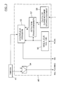
figure 3 est un schéma synoptique d'une unité d'émission selon l'invention, faisant partie d'une contrôle de paquets selon lafigure 2 ; - la
figure 4 est un organigramme d'une procédure de contrôle d'émission de blocs par une unité selon l'invention ; - les
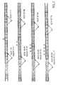
figures 5 ,7 et9 sont des diagrammes illustrant des exemples de transmission de blocs d'une séquence par une unité selon l'invention ; - à titre de comparaison, les
figures 6 ,8 et10 sont des diagrammes correspondant respectivement à ceux desfigures 5 ,7 et9 en l'absence d'application de l'invention. - L'invention est décrite ci-après dans son application à des réseaux GPRS (« General Packet Radio Service »). Ces réseaux ont été développés pour permettre la transmission de données en mode paquets dans des réseaux cellulaires de type GSM (« Global System for Mobile communications »). Pour l'illustration, on considérera la transmission de paquets dans le sens descendant, c'est-à-dire de l'infrastructure du réseau vers les stations mobiles. On comprendra toutefois que l'invention est applicable dans les deux sens de communication. Elle est d'autre part applicable à divers autres systèmes, notamment de type UMTS (« Universal Mobile Telecommunications System »).
- Le réseau GPRS illustré sur la
figure 1 est bâti sur une infrastructure GSM, et classiquement divisé en un coeur de réseau, aussi appelé sous-système de réseau et de commutation ou NSS (« Network and Switching Subsystem »), et un réseau d'accès radio également appelé sous-système de stations de base ou BSS (« Base Station Subsystem »). - Pour le service de paquets, les commutateurs du NSS sont appelés noeuds de support GPRS ou GSN (« GPRS Support Node »). On distingue les SGSN (« Serving GSN ») 5 qui sont reliés au BSS par l'intermédiaire d'une interface appelée Gb, et les GGSN (« Gateway GSN », non représentés) qui servent de passerelle avec des réseaux extérieurs de transmission de paquets, tels que par exemple le réseau Internet.
- Une description générale de l'interface radio, appelée Um, entre les stations mobiles (MS) 10 et les stations de base (BTS) 20 du BSS est fournie dans la spécification technique ETSl TS 101 350, « Digital cellular telecommunications system (Phase 2+) ; General Packet Radio Service (GPRS) ; Overall description of the GPRS radio interface ; Stage 2 (GSM 03.64, version 8.5.0, Release 1999), publiée par l'ETSl (European Telecommunications Standards Institute) en août 2000.
- Chaque station de base 20 est supervisée par un contrôleur de stations de base ou BSC (« Base Station Controller ») 21 par l'intermédiaire d'une interface appelée Abis. Pour gérer la transmission de paquets GPRS, le BSS comprend en outre une entité 22 appelée unité de contrôle de paquets ou PCU (« Packet Control Unit »). La localisation du PCU à l'intérieur du BSS n'est pas normalisée. Dans l'exemple représenté sur la
figure 1 , le PCU 22 est situé entre le BSC 21, avec lequel il communique à travers une interface appelée Agprs, et le NSS, avec lequel il communique à travers l'interface Gb. - La
figure 2 illustre une structure possible d'un PCU 22 situé entre un SGSN 5 et un BSC 21, comme dans l'exemple de lafigure 1 . La référence 40 désigne le contrôleur d'interface Gb pour la liaison avec le SGSN 5. - L'interface Gb est de type asynchrone. Elle repose sur le protocole de relais de trame (FR, « Frame Relay »), ainsi qu'un protocole appelé BSSGP (« BSS GPRS Protocol ») qui transporte des informations de routage et de qualité de service entre le BSS et le SGSN. Le contrôleur d'interface Gb 40 assure la liaison physique avec le SGSN 5, ainsi que les procédures propres aux protocoles FR et BSSGP.
- Les liaisons entre le PCU 22 et les BTS 20 à travers l'interface Agprs sont de type synchrone. En conséquence, les données manipulées par le PCU 22 entre le contrôleur d'interface Gb 40 et le contrôleur d'interface Agprs 42 transitent par une mémoire tampon 41 où sont enregistrées des files d'attente de paquets.
- Entre le PCU 22 et la BTS 20, les informations sont portées par des trames de type TRAU (« Transcoder/Rate Adaptor Unit ») de 320 bits, à raison d'une trame toutes les 20 ms. Ces trames TRAU sont mises en forme et traitées par un module 44 et transmises par l'intermédiaire de circuits d'interface synchrone 45 qui réalisent des sous-voies MlC à 16 kbit/s avec les BTS 20. Plusieurs sous-voies à 16 kbits peuvent être multiplexées sur l'interface Agprs et séparées par le BSC 21 pour l'acheminement vers les BTS. Un module 46 du contrôleur d'interface Agprs 42 met en oeuvre les protocoles radio de la couche 2 du modèle lSO, à savoir les protocoles RLC/MAC (« Radio Link Control / Medium Access Control ») décrits dans la norme européenne ETSl EN 301 349, Digital cellular telecommunications system (Phase 2+) ; General Packet Radio Service (GPRS) ; Mobile Station (MS) - Base Station System (BSS) interface ; Radio Link Control/Medium Access Control (RLC/MAC) protocol (GSM 04.60, version 8.3.1, Release 1999), publiée par l'ETSl en octobre 2000.
- La sous-couche RLC réalise l'interface avec le protocole de couche supérieure, appelé LLC (« Logical Link Control »). Elle assure la segmentation et le réassemblage des unités de données du protocole LLC (LLC-PDU), qui sont échangées de manière asynchrone sur l'interface Gb. Elle produit des blocs de données RLC auxquels la sous-couche MAC rajoute un en-tête MAC d'un octet.
- Dans le sens descendant, du PCU vers les MS, l'en-tête MAC de chaque bloc RLC/MAC inclut :
- un champ USF de trois bits (« Uplink State Flag »), servant à indiquer quelle station mobile est autorisée à utiliser une ressource montante correspondant à la ressource descendante sur laquelle est transmise le bloc RLC/MAC ;
- un champ de contrôle d'acquittement de trois bits, incluant un sous-champ d'un bit S/P (« Supplementary/Polling ») indiquant si le champ de contrôle d'acquittement est actif (S/P = 1) ou inactif (S/P = 0) et un sous-champ de deux bits RRBP (« Relative Reserved Block Period ») spécifiant de manière unique un bloc montant dans lequel la station mobile destinataire doit transmettre un message d'acquittement ;
- un champ « Payload Type » de deux bits spécifiant le type de bloc RLC suivant (données, contrôle, ...).
- On s'intéresse ici à la transmission de blocs de données RLC. Chacun de ces blocs comporte un en-tête RLC suivant l'octet d'en-tête MAC. Cet en-tête RLC comporte notamment les informations suivantes :
- identité de flux temporaire TFl (« Temporary Flow Identity »), composée de cinq bits identifiant le flux de blocs temporaire (TBF, « Temporary Block Flow ») d'où proviennent les données RLC du bloc. Un TBF est une connexion supportant le transfert unidirectionnel de LLC-PDU sur des canaux physiques de données. Un TBF est temporaire, c'est-à-dire qu'il n'est maintenu que pendant le transfert de données ;
- un numéro de séquence du bloc BSN (« Bloc Sequence Number ») de SNS bits, qui contient le numéro de séquence du bloc RLC/MAC dans le TBF, modulo 2SNS, SNS étant un nombre prédéfini.
- La sous-couche MAC gère en outre le multiplexage des blocs relevant des différents TBF actifs sur les canaux physiques disponibles, en arbitrant entre les différents utilisateurs mobiles par un mécanisme de planification (« scheduling »).
- L'entité RLC/MAC de la station mobile destinataire des blocs de données descendants d'un TBF tient à jour pour ce flux une variable d'état de réception V(R) qui indique le BSN suivant le BSN le plus élevé reçu sur ce TBF. Le nombre V(R)-1 (modulo 2SNS) pointe ainsi sur la fin d'une fenêtre de réception dont la longueur est de WS blocs RLC/MAC. A réception d'une commande de « polling », c'est-à-dire d'un bloc dont l'en-tête MAC a le bit S/P = 1, la MS retourne, dans le bloc montant spécifié par le sous-champ RRBP, un message d'acquittement PDAN (« Packet Downlink Ack/Nack ») qui comporte notamment :
- un champ SSN (« Starting Sequence Number ») de SNS bits contenant la variable V(R) courante pour le TBF ; et
- un champ RBB (« Receive Block Bitmap ») représentant une cartographie binaire (bitmap) de WS bits indiquant ceux des blocs de la fenêtre de réception qui ont été correctement reçus. Un acquittement positif du bloc BSN = (SSN - i) mod 2SNS est indiqué par la valeur 1 du bit de rang i (1 ≤ i ≤ k) du bitmap représenté par RRB, et un acquittement négatif par la valeur 0.
- A réception du message PDAN, le PCU met à jour pour le TBF une variable d'état d'acquittement V(A) qui contient le BSN du plus ancien bloc qui n'a pas été acquitté positivement, ainsi qu'un tableau V(B) à WS entrées indiquant les états d'acquittement respectifs de WS blocs consécutifs à partir de celui désigné par V(A), ces WS blocs consécutifs formant une fenêtre d'émission. Les états d'acquittement possibles sont : acquittement positif (ACK) ; acquittement négatif (NACK) ; et acquittement non encore reçu (ACK_PENDING). Les variables d'état V(A) et V(B) sont directement déduites des champs SSN et RBB reçus dans le dernier message PDAN. Le protocole RLC/MAC n'autorise la transmission de blocs qu'à l'intérieur de la fenêtre d'émission ainsi gérée par le PCU. En dehors de cette fenêtre, la transmission des blocs est inhibée.
- Dans le cas du GPRS, la norme spécifie les valeurs SNS = 7, WS = 64. Un niveau de protection variable peut être sélectionné bloc par bloc à l'intérieur d'un TBF, par le choix d'un schéma de codage CS (« Coding Scheme ») parmi quatre schémas CS-1 à CS-4 spécifiés dans la norme européenne ETSl EN 300 909, Digital cellular telecommunications system (Phase 2+) ; Channel coding (GSM 05.03, version 8.5.1, Release 1999), publiée par l'ETSI en novembre 2000.
- Le schéma CS-4 n'utilise pas de codage correcteur d'erreurs, c'est-à-dire que le rendement de codage vaut 1 : seule une séquence de vérification de bloc (BCS « Block Check Sequence ») est adjointe aux blocs de données. Les schémas CS-1 à CS-3 utilisent un code convolutif de rendement 1/2 après l'adjonction de la séquence BCS. Aucun poinçonnage n'est effectué dans le schéma CS-1 (qui offre le plus haut niveau de protection), tandis que des poinçonnages sont appliqués dans les schémas CS-2 et CS-3 afin qu'ils donnent lieu à des rendements de codage globaux d'environ 2/3 et d'environ 3/4, respectivement.
- Le codage de canal CS-i (1 ≤ i ≤4) est appliqué au niveau du protocole de couche physique, c'est-à-dire dans les BTS pour les liaisons descendantes. Chaque bloc RLC/MAC codé se compose de 456 bits et est transmis dans des intervalles de temps correspondants de quatre trames TDMA sur une fréquence porteuse, les trames TDMA successives (« Time-Division Multiple Access ») étant chacune décomposées en huit intervalles de temps pour assurer un multiplexage temporel de canaux.
- Un motif de huit bits de signalisation SB est inséré dans chaque trame codée (deux bits par intervalle de temps) afin d'indiquer notamment quel schéma de codage a été appliqué par l'émetteur.
- Ces bits de signalisation sont extraits du bloc codé reçu par le destinataire, pour lui permettre d'identifier le schéma de codage. Le récepteur procède alors au décodage adéquat du bloc qui donnera lieu à un acquittement positif s'il est réussi et si la BCS décodée est cohérente avec le contenu du bloc.
- Le schéma de codage appliqué sur la liaison descendante est déterminé de façon connue en soi par le PCU en fonction de mesures de qualité de réception sur le lien radio, selon des mécanismes d'adaptation de lien qui cherchent à atteindre un objectif en termes de taux de blocs erronés afin d'optimiser le débit brut. Le schéma sélectionné est inséré dans la trame TRAU portant le bloc pour être appliqué par la BTS.
- Les normes précitées de l'ETSl spécifient aussi une extension du système GPRS, utilisant la modulation EDGE (« Enhanced Data for GSM Evolution »). Cette extension est appelée EGPRS (EDGE-GPRS).
- Dans un système EGPRS, la couche RLC/MAC utilise SNS = 11, et WS réglable entre 64 et 1024. Les en-têtes RLC et MAC sont regroupés en un seul en-tête RLC/MAC qui n'a plus le champ « Payload Type » et dans lequel le bit S/P est remplacé par un sous-champ ES/P de deux bits permettant de spécifier différents formats d'acquittement en cas de polling (ES/P ≠ 00). Neuf schémas de modulation et de codage, appelés MCS-1 à MCS-9, sont prévus. Le schéma utilisé pour un bloc donné, ainsi qu'un schéma de poinçonnage éventuellement appliqué, sont indiqués dans un champ CPS (« Coding and Puncturing Scheme indicator ») de l'en-tête RLC/MAC EGPRS.
- L'ensemble de l'en-tête RLC/MAC EGPRS fait l'objet d'un codage de canal distinct de celui des données du bloc. Le niveau de protection de cet en-tête contre les erreurs de transmission est plus élevé que celui des données pour assurer une meilleure robustesse des informations de signalisation.
- La
figure 3 illustre une organisation possible de l'entité RLC/MAC 46 du PCU pour un TBF descendant. Les données des LLC-PDU, segmentées en blocs RLC/MAC, sont conservées dans la mémoire tampon 41 jusqu'à ce que ces blocs aient été acquittés positivement. Le contrôleur d'émission 53 assure notamment les fonctions suivantes : - sélection d'un TBF pour chaque période d'émission sur le canal, par un mécanisme connu de planification ;
- pour le TBF sélectionné, sélection d'un bloc RLC/MAC à émettre, sur la base notamment des variables d'états V(A) et V(B) et de la présence ou absence d'un nouveau bloc dans la file d'attente relative au TBF dans le tampon d'émission 41 (cette sélection du bloc RLC à émettre sera expliquée plus en détail en référence à la
figure 4 ) ; - sélection du schéma de codage CS-i que la BTS 20 appliquera au bloc, et affectation de la valeur correspondante au motif de huit bits de signalisation SB. Si le mécanisme d'ARQ a conduit à sélectionner un bloc déjà émis auparavant, le schéma de codage retenu peut être le même (cas GPRS) ou un schéma plus robuste (option en EGPRS). Si le bloc sélectionné est un nouveau bloc, le schéma de codage est déterminé par un mécanisme d'adaptation de lien connu en soi ;
- lorsque le bloc sélectionné est un nouveau bloc, extraction du tampon 41 d'un nombre de bits d'information correspondant à la taille définie pour le schéma de codage retenu ; sinon, nouvelle extraction des données du bloc précédemment émis ;
- détermination du contenu de l'en-tête RLC/MAC et commande de l'insertion de cet en-tête par le module 54. Le contrôleur 53 positionne notamment les champs TFl et BSN ainsi que le champ de contrôle d'acquittement S/P-RRBP pour demander les acquittements de la part de la MS (« polling »). A titre d'illustration, il peut faire un « polling » tous les douze blocs émis ;
- Le bloc RLC/MAC délivré par le module 54 et les bits SB font partie des informations placées dans une trame TRAU transmise à la BTS concernée.
- Le module 55 représenté sur la
figure 3 traite les messages PDAN reçus en provenance de la MS destinataire pour mettre à jour les variables d'état V(A) et V(B) du TBF. Les blocs du TBF qui ont été émis par le PCU après le bloc de « polling » auquel répond un message PDAN restent à l'état ACK_PENDING, tandis que les autres blocs qui ont été émis jusqu'à ce bloc de « polling » sont mis à l'état ACK ou NACK selon la valeur du bit correspondant du bitmap RBB (en EGPRS, ce bitmap RBB peut être transmis sous forme comprimée, et il doit alors être décodé de façon correspondante par le module 55). - Conformément à l'invention, le contrôle de l'émission des blocs sur un TBF dépend aussi d'une estimation de la vitesse de déplacement v de la station mobile concernée. Plus généralement, tout paramètre, mesuré ou estimé, lié à cette vitesse de déplacement peut être utilisé.
- A titre d'exemple, la vitesse v peut être estimée de façon connue en soi en analysant les variations dans le temps de la puissance des signaux radio reçus par la BTS 20 en provenance de la MS 10 (ou en sens inverse par la MS 10 en provenance de la BTS 20). Un exemple possible de méthode d'estimation est décrit dans
FR-A-2 782 227 - Celui-ci comprend un module 56 qui détermine une durée typique d'évanouissement D à partir de la vitesse estimée v. Cette durée D peut notamment être une durée moyenne d'évanouissement calculable comme la largeur du pic de la fonction de corrélation du processus statistique de fading de Rayleigh selon une modélisation donnée, par exemple le modèle de Jakes. Les valeurs de la durée D en fonction de v peuvent être calculées une fois pour toutes et mémorisées dans une table de correspondance du module 56. Ces valeurs de D sont avantageusement exprimées en nombres entiers de blocs émis, sachant qu'il y a typiquement un bloc toutes les 20 ms par TBF.
- A titre d'exemple, pour une transmission sur une fréquence porteuse à 900 MHz et une station mobile qui se déplace à 1 km/h, la durée moyenne d'un évanouissement de plus de -20 dB par rapport à la valeur RMS (« root-mean square ») est d'environ 130 ms, et on peut prendre D = 6.
- Un module de détection d'évanouissements 57 de l'entité RLC/MAC examine les messages PDAN (ou les variables d'état V(A) et V(B) qui en sont déduites par le module 55) pour détecter certains évanouissements du canal radio sur la base des blocs acquittés négativement. Les évanouissements faisant l'objet de cette détection sont ceux qui portent sur un ou plusieurs blocs consécutifs émis à la fin de la période de « polling » qui se termine par le bloc de « polling » auquel répond le message PDAN, et dont la durée détectée est inférieure à D. Il y a de fortes chances pour qu'un ou plusieurs blocs suivants, émis juste après ce bloc de « polling », aient également expérimenté les conditions d'évanouissement. Pour augmenter cette probabilité, le module 56 peut adopter une durée D un peu réduite par rapport à la moyenne calculée (par exemple D = 5 dans l'exemple numérique précédent).
- Dans l'exemple représenté, la sortie du module de détection 57 après réception d'un message PDAN est un nombre N estimant le nombre de blocs à l'état ACK_PENDING qui ont émis juste après le bloc de « polling » en expérimentant vraisemblablement des conditions d'évanouissement détectées d'après ce message PDAN.
- En d'autres termes, si le module 57 détecte juste à la fin de la période de « polling » un évanouissement portant sur M blocs avec M < D, alors, il prend N = D - M. Sinon, il prend N = 0.
- En EGPRS, on a vu que l'en-tête RLC/MAC est plus protégé que les données du bloc RLC. En général, le contenu de l'en-tête résiste aux conditions d'évanouissement, de sorte que, même si le bloc qui porte la commande de « polling » (S/P = 1 ou ES/P ≠ 00) est acquitté négativement, cette commande peut être obtenue et traitée par la MS. La détection par le module 57 d'un évanouissement portant sur M blocs EGPRS juste à la fin de la période de « polling » résulte alors de la constatation de M blocs consécutifs à l'état NACK dans V(B).
- En GPRS, il n'est pas possible de protéger davantage le champ de contrôle d'acquittement S/P-RRBP que les données d'un bloc. Toutefois, le contrôleur 53 peut sélectionner bloc par bloc le schéma de codage appliqué CS-i. On procède avantageusement comme suit. Chaque fois qu'un schéma de codage autre que CS-1 est déterminé par les mécanismes d'adaptation de lien, le contrôleur 53 sélectionne un schéma plus robuste aux erreurs pour chaque bloc dont l'en-tête MAC a le bit S/P = 1. En particulier le schéma CS-1 (niveau de protection maximal) peut être retenu de façon systématique pour ces blocs de « polling ». Dans ce cas, la détection par le module 57 d'un évanouissement portant sur M blocs GPRS juste à la fin de la période de « polling » résulte de la constatation de M-1 blocs consécutifs à l'état NACK dans V(B) suivis par un bloc à l'état ACK correspondant au bloc de « polling » transmis de façon plus robuste.
- La
figure 4 montre une procédure applicable par le contrôleur 53 pour commander l'émission d'un bloc d'un TBF qui a été sélectionné par le processus de planification d'émission, conformément au protocole RLC. Le contrôleur examine d'abord le tableau V(B) pour déterminer s'il désigne un ou plusieurs blocs à l'état NACK (test 60). Si tel est le cas, le bloc à l'état NACK ayant le plus petit numéro de séquence BSN est sélectionné à l'étape 61 pour être répété, et ce bloc est ensuite passé à l'état ACK_PENDING dans le tableau V(B) à l'étape 62. - En l'absence de bloc acquitté négativement (aucun bloc à l'état NACK au test 60), le contrôleur 53 exécute les opérations suivantes :
- si V(S) < V(A) + WS modulo 2SNS (test 65), il examine s'il y a dans le tampon d'émission 41 un bloc en attente pour le TBF courant avec BSN = V(S) (test 66). La variable V(S) représente le numéro de séquence du « nouveau » bloc à émettre dont le BSN est minimal (initialisée à 0, comme le BSN, au début du TBF) ;
- si ce bloc BSN = V(S) est en attente d'émission, il est sélectionné à l'étape 67 puis passé à l'état ACK_PENDING dans le tableau V(B) à l'étape 62, après incrémentation d'une unité, modulo 2SNS, de la variable V(S) (étape 68) ;
- si le bloc BSN = V(S) n'est pas encore dans le tampon d'émission 41, le bloc sélectionné à l'étape 69 est le prochain bloc à l'état ACK_PENDING. Ce « prochain bloc » est le plus ancien (BSN minimal) dont la valeur dans le tableau V(B) indique l'état ACK_PENDING, puis le suivant, etc.
- si V(S) = V(A) + WS modulo 2SNS au test 65, il y a blocage de la fenêtre d'émission (« stalling ») : l'éventuel bloc en attente avec BSN = V(S) ne peut pas être émis, et le contrôleur passe à l'étape 69 précitée pour sélectionner le prochain bloc à l'état ACK_PENDING.
- Quand N > 0 à l'issue des traitements effectués par les modules 55 et 57 d'après un message PDAN répondant à bloc de « polling » donné, le contrôleur 53 tient compte d'un évanouissement dont le début a été détecté par le module 57. Il détermine si les N blocs émis au cours des N périodes d'émission allouées au TBF après le bloc de « polling » auquel a répondu le message PDAN qui a donné lieu à cette valeur N > 0 ont déjà été émis au moins une fois supplémentaire après ces N périodes d'émission. Chaque variable d'état du tableau V(B) qui correspond à l'un de ces N blocs qui n'a pas été ré-émis est passée de l'état ACK_PENDING à l'état NACK. Ceci a pour effet de forcer une répétition en aveugle de ces blocs vraisemblablement mal reçus (étape 69). Cette répétition en aveugle a lieu juste après la répétition du ou des blocs ayant effectivement fait l'objet d'un acquittement négatif.
- En EGPRS, le contrôleur 53 peut en outre sélectionner, pour chacune de ces répétitions de l'étape 69 (en aveugle ou non), un niveau de protection contre les erreurs de transmission supérieur à celui résultant des mécanismes généraux d'adaptation de lien, afin d'augmenter la probabilité de bonne réception du bloc répété. Une autre possibilité est d'envoyer, en tant que répétition de ce bloc, de la redondance incrémentale selon un mécanisme connu d'ARQ hybride.
- Dans une variante de réalisation de l'invention, la durée typique d'évanouissement D, qui est liée à la vitesse v, peut être estimée directement par une moyenne statistique des durées d'évanouissement, en nombres de blocs, constatées d'après les acquittements négatifs remontés dans les messages PDAN.
- Les
figures 5 à 10 illustrent la prise en compte de l'information de vitesse dans le contrôle d'émission des blocs sur un TBF. Les numéros dessinés sont les BSN des blocs. Chaque diagramme correspond à un cas où le PCU active le champ de contrôle d'acquittement (flèches descendantes) tous les douze blocs. Dans chaque diagramme, les blocs représentés en pointillés sont acquittés négativement (ils ont été émis pendant un évanouissement de canal). La même séquence d'évanouissements a été prise en compte sur les six figures, et on suppose, pour mieux montrer les avantages procurés, que chacun de ces évanouissements à la durée D = 5 retenue par le module 56. Les flèches montantes représentent les messages PDAN répondant aux blocs de « polling ». A côté de chacune de ces flèches montantes, on a indiqué les blocs de la fenêtre d'émission qui sont respectivement aux états ACK et NACK après la prise en compte d'un message PDAN (les blocs non spécifiés sont à l'état ACK_PENDING). Lesfigures 5 ,7 et9 correspondent à la mise en oeuvre de l'invention et sont à comparer respectivement auxfigures 6 ,8 et10 correspondant à la mise en oeuvre de la même méthode sans prise en compte de l'information de vitesse. - L'exemple des
figures 5 et6 est un cas EGPRS : le message PDAN peut être élaboré et retourné au PCU alors que les données du bloc de « polling » auquel il répond sont acquittées négativement. On a supposé que le temps d'aller-retour entre l'émission d'un bloc de « polling » par le PCU et sa réception du message PDAN qui lui répond correspond à une période d'environ douze blocs (valeur typique du cas où le PCU est localisé au même endroit que le SGSN). Le symbole « B » sur lafigure 5 représente les blocs ré-émis en aveugle par le PCU, parce qu'ils ont été artificiellement placés à l'état NACK en réponse à la détection d'un début d'évanouissement. On voit que ces blocs ré-émis en aveugle diminuent de façon appréciable le retard de transmission sur le TBF par rapport à la méthode classique illustrée par lafigure 6 . Dans l'exemple dessiné, la méthode classique conduit de plus à un blocage de fenêtre (blocs assortis du symbole « S », répétés à l'état ACK_PENDING suivant l'étape 69 jusqu'à acquittement positif du bloc BSN = 11), que la prise en compte de l'information de vitesse permet d'éviter (cas WS = 64). - L'exemple des
figures 7 et8 est aussi un cas EGPRS, avec un temps d'aller-retour d'environ trois blocs (valeur typique du cas où le PCU est localisé au même endroit que la BTS). On constate aussi une diminution des retards de transmission (par exemple, le bloc BSN = 30 est reçu dix blocs plus tôt, soit environ 200 ms, sur lafigure 7 que sur lafigure 8 ). Dans cet exemple, la durée typique d'évanouissement D est plus longue que le temps d'aller-retour. Il se peut donc (dernières lignes desfigures 7 et8 ) qu'un évanouissement, dont le début est détecté à réception d'un message PDAN, se prolonge sur un ou plusieurs blocs au delà de cette réception. Lorsque cela se produit, le contrôleur 53 retarde la répétition des blocs à l'état NACK jusqu'à l'expiration de la durée D à compter du début d'évanouissement détecté. Si un bloc est émis avant cette expiration (le bloc BSN = 71 dans l'exemple de lafigure 7 ), le contrôleur 53 le maintient à l'état NACK afin qu'il puisse être ré-émis sans attendre la réception et le traitement du prochain message PDAN. En variante, le contrôleur 53 ne maintient pas ce bloc 71 à l'état NACK après sa première émission, mais il choisit pour cette première émission un schéma de codage plus robuste aux erreurs que celui appliqué aux autres blocs du TBF, afin d'anticiper des conditions de propagation difficiles grâce à l'information de vitesse. - L'exemple des
figures 9 et10 est un cas GPRS, avec un temps d'aller-retour d'environ douze blocs. On peut voir que dans ce cas aussi, la prise en compte de l'information de vitesse diminue le retard de transmission sur le TBF et réduit la probabilité de blocage de fenêtre.
Claims (9)
- Procédé d'émission de blocs de données sur un canal de communication comportant un lien radio entre deux stations incluant une station mobile, ledit procédé comprenant des étapes consistant à :- obtenir une séquence de blocs de données à émettre sur ledit canal,- recevoir des informations d'acquittement des blocs de la séquence depuis une unité destinataire et- contrôler l'émission des blocs de la séquence sur le canal sur la base d'informations de contrôle d'émission incluant les informations d'acquittement reçues de l'unité destinataire et un indicateur d'évanouissement déduit desdites informations d'acquittement et d'une grandeur estimée (v) liée à une vitesse de déplacement de la station mobile.
- Procédé d'émission de blocs de données selon la revendication 1, dans lequel l'étape consistant à contrôler l'émission des blocs de la séquence sur le canal comprend des étapes consistant à :- déterminer une durée typique d'évanouissement de canal (D) en fonction de ladite grandeur estimée (v) liée à la vitesse de la station mobile, et- détecter des évanouissements de canal couvrant chacun un ou plusieurs blocs émis consécutivement, le début et la fin d'un évanouissement étant détectés sur la base des informations d'acquittement reçues depuis l'unité destinataire, et- dans laquelle contrôler l'émission des blocs est effectué en se basant sur chaque évanouissement détecté d'une durée inférieure à la durée typique déterminée (D), le début détecté dudit évanouissement étant situé après la réception d'informations d'acquittement tandis que la fin dudit évanouissement n'est pas encore détectée.
- Procédé d'émission de blocs de données selon la revendication 1 dans lequel l'étape consistant à contrôler l'émission des blocs de la séquence sur le canal comprend des étapes consistant à :- sélectionner (53) des blocs de la séquence à émettre respectivement sur le canal au cours de périodes d'émission successivement affectées à l'unité destinataire, le bloc sélectionné pour une période d'émission étant fonction des informations d'acquittement reçues de l'unité destinataire et de ladite grandeur estimée (v) liée à la vitesse de la station mobile.
- Procédé d'émission de blocs de données selon la revendication 3, comprenant des étapes consistant à :- activer de façon intermittente un champ de contrôle d'acquittement prévu dans un en-tête de chaque bloc émis sur le canal, pour requérir un acquittement de blocs de la part de l'unité destinataire, et dans lequel- l'étape consistant à contrôler l'émission des blocs de la séquence sur le canal comprend des étapes consistant à :- traiter des informations d'acquittement reçues depuis l'unité destinataire en réponse à la réception d'un bloc ayant le champ de contrôle d'acquittement activé, pour affecter un premier état (ACK) aux blocs de la séquence acquittés par l'unité destinataire, un second état (NACK) aux blocs non acquittés de la séquence qui n'ont pas été émis après ledit bloc ayant le champ de contrôle d'acquittement activé et un troisième état (ACK_PENDING) aux blocs non acquittés de la séquence qui ont été émis après ledit bloc ayant le champ de contrôle d'acquittement activé, et dans laquelle- sélectionner des blocs (53) comprend sélectionner un bloc de la séquence pour chaque période d'émission affectée à l'unité destinataire sur la base des états respectivement affectés aux blocs précédemment émis sur le canal et de ladite grandeur estimée (v) liée à la vitesse de la station mobile.
- Procédé d'émission de blocs de données selon chacune des revendications 2 et 4, dans lequel l'étape consistant à contrôler l'émission des blocs de la séquence sur le canal comprend une étape consistant à :affecter, en réponse à la détection d'un évanouissement sur une durée inférieure à la durée typique déterminée (D), dont le début a été détecté après la réception d'informations d'acquittement répondant à la réception d'un bloc ayant le champ de contrôle d'acquittement activé mais dont la fin n'a pas été détectée, le second état à au moins un bloc non acquitté de la séquence qui a été émis après ledit bloc ayant le champ de contrôle d'acquittement activé et avant que la durée typique déterminée se soit écoulée à compter du début de l'évanouissement détecté.
- Procédé d'émission de blocs de données selon la revendication 5, comprenant une étape consistant à appliquer une protection plus forte contre les erreurs de transmission au champ de contrôle d'acquittement qu'à une partie au moins des données de chaque bloc.
- Procédé d'émission de blocs de données selon la revendication 5, comprenant une étape consistant à appliquer une protection plus forte contre les erreurs de transmission aux blocs ayant le champ de contrôle d'acquittement activé qu'aux blocs n'ayant pas le champ de contrôle d'acquittement activé.
- Procédé d'émission de blocs de données selon la revendication 2, dans lequel l'étape consistant à contrôler l'émission des blocs de la séquence sur le canal comprend une étape consistant à :sélectionner un niveau de protection contre les erreurs pour la transmission de chaque bloc de la séquence à émettre respectivement sur le canal au cours de périodes d'émission successivement affectées à l'unité destinataire, le niveau sélectionné pour une période d'émission étant fonction des informations d'acquittement reçues de l'unité destinataire et de ladite grandeur estimée (v) liée à la vitesse de la station mobile.
- Procédé d'émission de blocs de données selon la revendication 8, dans lequel les niveaux de protection contre les erreurs résultent d'un codage de canal de rendement réglable auquel les blocs sont soumis.
Applications Claiming Priority (2)
| Application Number | Priority Date | Filing Date | Title |
|---|---|---|---|
| FR0103614A FR2822317B1 (fr) | 2001-03-16 | 2001-03-16 | Unite d'emission de blocs de donnees en mode acquitte sur un canal comportant un lien radio avec une station mobile |
| EP02290638.2A EP1241822B1 (fr) | 2001-03-16 | 2002-03-13 | Unite d'émission de blocs de données en mode acquitte vers une station mobile |
Related Parent Applications (3)
| Application Number | Title | Priority Date | Filing Date |
|---|---|---|---|
| EP02290638.2A Division-Into EP1241822B1 (fr) | 2001-03-16 | 2002-03-13 | Unite d'émission de blocs de données en mode acquitte vers une station mobile |
| EP02290638 Previously-Filed-Application | 2002-03-13 | ||
| EP02290638.2 Division | 2002-03-13 |
Publications (2)
| Publication Number | Publication Date |
|---|---|
| EP2326038A1 true EP2326038A1 (fr) | 2011-05-25 |
| EP2326038B1 EP2326038B1 (fr) | 2013-07-10 |
Family
ID=8861223
Family Applications (2)
| Application Number | Title | Priority Date | Filing Date |
|---|---|---|---|
| EP10195884.1A Expired - Lifetime EP2326038B1 (fr) | 2001-03-16 | 2002-03-13 | Procédé d'émission de blocs de données en mode acquitté vers une station mobile |
| EP02290638.2A Expired - Lifetime EP1241822B1 (fr) | 2001-03-16 | 2002-03-13 | Unite d'émission de blocs de données en mode acquitte vers une station mobile |
Family Applications After (1)
| Application Number | Title | Priority Date | Filing Date |
|---|---|---|---|
| EP02290638.2A Expired - Lifetime EP1241822B1 (fr) | 2001-03-16 | 2002-03-13 | Unite d'émission de blocs de données en mode acquitte vers une station mobile |
Country Status (3)
| Country | Link |
|---|---|
| US (1) | US7197050B2 (fr) |
| EP (2) | EP2326038B1 (fr) |
| FR (1) | FR2822317B1 (fr) |
Families Citing this family (41)
| Publication number | Priority date | Publication date | Assignee | Title |
|---|---|---|---|---|
| FR2843670B1 (fr) * | 2002-08-14 | 2005-01-14 | Evolium Sas | Procede pour l'allocation de ressources en mode paquet dans un systeme de radiocommunications mobiles |
| US7542471B2 (en) | 2002-10-30 | 2009-06-02 | Citrix Systems, Inc. | Method of determining path maximum transmission unit |
| US7616638B2 (en) | 2003-07-29 | 2009-11-10 | Orbital Data Corporation | Wavefront detection and disambiguation of acknowledgments |
| US8233392B2 (en) * | 2003-07-29 | 2012-07-31 | Citrix Systems, Inc. | Transaction boundary detection for reduction in timeout penalties |
| US8270423B2 (en) | 2003-07-29 | 2012-09-18 | Citrix Systems, Inc. | Systems and methods of using packet boundaries for reduction in timeout prevention |
| US7630305B2 (en) | 2003-07-29 | 2009-12-08 | Orbital Data Corporation | TCP selective acknowledgements for communicating delivered and missed data packets |
| US7385926B2 (en) * | 2002-11-25 | 2008-06-10 | Intel Corporation | Apparatus to speculatively identify packets for transmission and method therefor |
| FR2850516B1 (fr) * | 2003-01-29 | 2005-06-03 | Evolium Sas | Procede pour obtimiser les performances d'un systeme de radiocommunications mobile |
| DE10325298B4 (de) * | 2003-06-04 | 2007-07-05 | Siemens Ag | Verfahren und Vorrichtung zur Erfassung der Rauigkeit von Gefäßen |
| US6845235B1 (en) * | 2003-07-18 | 2005-01-18 | Motorola, Inc. | Method and apparatus in a wireless communication system for expediting a request for uplink resources |
| KR100568232B1 (ko) * | 2003-07-28 | 2006-04-07 | 삼성전자주식회사 | 모바일 애드 혹 네트워크에서 전송층을 이용한 효율적인데이터 송수신 방법 및 상기 방법을 이용한 네트워크 장치 |
| US8437284B2 (en) | 2003-07-29 | 2013-05-07 | Citrix Systems, Inc. | Systems and methods for additional retransmissions of dropped packets |
| US8238241B2 (en) | 2003-07-29 | 2012-08-07 | Citrix Systems, Inc. | Automatic detection and window virtualization for flow control |
| US8432800B2 (en) | 2003-07-29 | 2013-04-30 | Citrix Systems, Inc. | Systems and methods for stochastic-based quality of service |
| US7698453B2 (en) | 2003-07-29 | 2010-04-13 | Oribital Data Corporation | Early generation of acknowledgements for flow control |
| US7656799B2 (en) | 2003-07-29 | 2010-02-02 | Citrix Systems, Inc. | Flow control system architecture |
| US7978716B2 (en) | 2003-11-24 | 2011-07-12 | Citrix Systems, Inc. | Systems and methods for providing a VPN solution |
| KR101008623B1 (ko) * | 2003-12-02 | 2011-01-17 | 엘지전자 주식회사 | 순방향 수신 확인 채널의 전송 전력 제어 방법 및 수신확인 제어 방법 |
| US7190980B2 (en) * | 2004-01-30 | 2007-03-13 | Hewlett-Packard Development Company, L.P. | Method and system for power control in wireless portable devices using wireless channel characteristics |
| US20050180325A1 (en) * | 2004-02-13 | 2005-08-18 | Nokia Corporation | Method of controlling data transmission, radio system, packet control unit, and remote network element |
| US8495305B2 (en) | 2004-06-30 | 2013-07-23 | Citrix Systems, Inc. | Method and device for performing caching of dynamically generated objects in a data communication network |
| US7757074B2 (en) | 2004-06-30 | 2010-07-13 | Citrix Application Networking, Llc | System and method for establishing a virtual private network |
| US8739274B2 (en) | 2004-06-30 | 2014-05-27 | Citrix Systems, Inc. | Method and device for performing integrated caching in a data communication network |
| US8223647B2 (en) * | 2004-07-21 | 2012-07-17 | Nokia Corporation | System and method for increasing data throughout using a block acknowledgement |
| CN101199187A (zh) | 2004-07-23 | 2008-06-11 | 茨特里克斯系统公司 | 用于网络节点之间通信最优化的系统和方法 |
| KR20070045282A (ko) | 2004-07-23 | 2007-05-02 | 사이트릭스 시스템스, 인크. | 네트워크 노드 간의 통신을 최적화하기 위한 시스템 및방법 |
| US8706877B2 (en) | 2004-12-30 | 2014-04-22 | Citrix Systems, Inc. | Systems and methods for providing client-side dynamic redirection to bypass an intermediary |
| US8549149B2 (en) | 2004-12-30 | 2013-10-01 | Citrix Systems, Inc. | Systems and methods for providing client-side accelerated access to remote applications via TCP multiplexing |
| US8954595B2 (en) | 2004-12-30 | 2015-02-10 | Citrix Systems, Inc. | Systems and methods for providing client-side accelerated access to remote applications via TCP buffering |
| US8700695B2 (en) | 2004-12-30 | 2014-04-15 | Citrix Systems, Inc. | Systems and methods for providing client-side accelerated access to remote applications via TCP pooling |
| US7810089B2 (en) | 2004-12-30 | 2010-10-05 | Citrix Systems, Inc. | Systems and methods for automatic installation and execution of a client-side acceleration program |
| CA2594983A1 (fr) | 2005-01-24 | 2006-08-03 | Citrix Systems, Inc. | Systemes et procedes pour mettre en memoire cache des objets produits dynamiquement dans un reseau |
| US8255456B2 (en) | 2005-12-30 | 2012-08-28 | Citrix Systems, Inc. | System and method for performing flash caching of dynamically generated objects in a data communication network |
| US7921184B2 (en) | 2005-12-30 | 2011-04-05 | Citrix Systems, Inc. | System and method for performing flash crowd caching of dynamically generated objects in a data communication network |
| US8301839B2 (en) | 2005-12-30 | 2012-10-30 | Citrix Systems, Inc. | System and method for performing granular invalidation of cached dynamically generated objects in a data communication network |
| US20070249343A1 (en) * | 2006-04-19 | 2007-10-25 | Andreas Olsson | Method and system of communications |
| US8031680B2 (en) * | 2006-05-18 | 2011-10-04 | Motorola Mobility, Inc. | Communicating non-scheduling information in wireless networks |
| US10372527B2 (en) | 2013-07-15 | 2019-08-06 | Intel Corporation | Method of encoding data |
| US10834065B1 (en) | 2015-03-31 | 2020-11-10 | F5 Networks, Inc. | Methods for SSL protected NTLM re-authentication and devices thereof |
| US10404698B1 (en) | 2016-01-15 | 2019-09-03 | F5 Networks, Inc. | Methods for adaptive organization of web application access points in webtops and devices thereof |
| EP4005129B1 (fr) * | 2019-07-26 | 2024-10-23 | Samsung Electronics Co., Ltd. | Procédé et appareil pour améliorer une procédure harq dans un réseau non terrestre |
Citations (2)
| Publication number | Priority date | Publication date | Assignee | Title |
|---|---|---|---|---|
| US5602831A (en) * | 1995-03-31 | 1997-02-11 | Seiko Communications Systems, Inc. | Optimizing packet size to eliminate effects of reception nulls |
| JP2000069037A (ja) * | 1998-08-25 | 2000-03-03 | Nippon Telegr & Teleph Corp <Ntt> | 無線パケット伝送装置 |
Family Cites Families (3)
| Publication number | Priority date | Publication date | Assignee | Title |
|---|---|---|---|---|
| JPH0618358B2 (ja) * | 1985-04-09 | 1994-03-09 | 沖電気工業株式会社 | 誤り制御符号化方式 |
| US5828677A (en) * | 1996-03-20 | 1998-10-27 | Lucent Technologies Inc. | Adaptive hybrid ARQ coding schemes for slow fading channels in mobile radio systems |
| US6907005B1 (en) * | 2000-07-24 | 2005-06-14 | Telefonaktiebolaget L M Ericsson (Publ) | Flexible ARQ for packet data transmission |
-
2001
- 2001-03-16 FR FR0103614A patent/FR2822317B1/fr not_active Expired - Lifetime
-
2002
- 2002-03-12 US US10/095,729 patent/US7197050B2/en not_active Expired - Lifetime
- 2002-03-13 EP EP10195884.1A patent/EP2326038B1/fr not_active Expired - Lifetime
- 2002-03-13 EP EP02290638.2A patent/EP1241822B1/fr not_active Expired - Lifetime
Patent Citations (2)
| Publication number | Priority date | Publication date | Assignee | Title |
|---|---|---|---|---|
| US5602831A (en) * | 1995-03-31 | 1997-02-11 | Seiko Communications Systems, Inc. | Optimizing packet size to eliminate effects of reception nulls |
| JP2000069037A (ja) * | 1998-08-25 | 2000-03-03 | Nippon Telegr & Teleph Corp <Ntt> | 無線パケット伝送装置 |
Non-Patent Citations (1)
| Title |
|---|
| PATENT ABSTRACTS OF JAPAN vol. 2000, no. 06 22 September 2000 (2000-09-22) * |
Also Published As
| Publication number | Publication date |
|---|---|
| US7197050B2 (en) | 2007-03-27 |
| FR2822317B1 (fr) | 2003-08-08 |
| EP2326038B1 (fr) | 2013-07-10 |
| EP1241822A1 (fr) | 2002-09-18 |
| FR2822317A1 (fr) | 2002-09-20 |
| US20020150064A1 (en) | 2002-10-17 |
| EP1241822B1 (fr) | 2019-05-08 |
Similar Documents
| Publication | Publication Date | Title |
|---|---|---|
| EP2326038B1 (fr) | Procédé d'émission de blocs de données en mode acquitté vers une station mobile | |
| EP1179910B1 (fr) | Commande de la liaison radio avec retransmissions limitées pour services en continu | |
| US7345999B2 (en) | Methods and devices for the retransmission of data packets | |
| EP1123601B1 (fr) | Protocole arq avec reglage du niveau de fiabilite a base de paquets | |
| CN100512087C (zh) | 用于否定帧应答的控制的空闲帧的利用 | |
| EP2567490B1 (fr) | Procédés et agencements pour rétroaction harq précoce dans un système de communication mobile | |
| EP2052484B1 (fr) | Analyse transitoire de perte de paquets en file d'attente dans un réseau de diffusion | |
| FR2819661A1 (fr) | Procede et dispositifs de transmission de donnees avec mecanisme d'acquittement | |
| EP2003810A2 (fr) | Dispositif de gestion de réception par des terminaux de contenus multimédia transmis par des infrastructures mettant en oeuvre des techniques de transmission différentes | |
| Luo et al. | Delay analysis of selective-repeat ARQ with applications to link adaptation in wireless packet data systems | |
| EP1370020B1 (fr) | Procédé et unité de contrôle d'adaptation de liens radio | |
| EP1362449B1 (fr) | Procede de transmission de donnees avec un niveau de protection contre les erreurs selectionne parmi plusieurs niveaux predefinis | |
| EP1274265B1 (fr) | Procédé d'émission de blocs de signal modulé, station émettrice et source de données pour la mise en oeuvre du procédé | |
| EP1179911A1 (fr) | Procédé pour évaluer la qualité d'une liaison radio dans un système de radiocommunications mobiles | |
| EP2441223B1 (fr) | Procede et dispositifs d'emission et reception de symboles multi porteuse | |
| MX2011007713A (es) | Esquema de retransmision de datos. | |
| EP1411689A1 (fr) | Procédé de contrôle de retransmission de données et unité de contrôle pour mettre en oeuvre le procédé | |
| EP1473839B1 (fr) | Procédé et dispositif de réception de blocs de données avec correction et detection d'erreurs | |
| WO2006012772A1 (fr) | Procede de transmission sur reseau local etendu | |
| KR101376460B1 (ko) | 통신 시스템에서 패킷 전송 장치 및 방법 | |
| EP1471758A1 (fr) | Procédé et unité de contrôle des changements de schéma de codage (coding scheme CS) dans un système de radiocommunication | |
| EP1443778A1 (fr) | Procédé pour optimiser les performances d'un système de radiocommunications mobiles | |
| EP2003807A1 (fr) | Dispositif et procédé de décodage de mot de contrôle codé par maximasion de probabilité à posteriori | |
| Li | Link Adaptation in General Packet Radio Services (GPRS) | |
| FR2864383A1 (fr) | Procede de traitement d'informations transmises sur un canal partage et station de base pour la mise en oeuvre du procede |
Legal Events
| Date | Code | Title | Description |
|---|---|---|---|
| PUAI | Public reference made under article 153(3) epc to a published international application that has entered the european phase |
Free format text: ORIGINAL CODE: 0009012 |
|
| AC | Divisional application: reference to earlier application |
Ref document number: 1241822 Country of ref document: EP Kind code of ref document: P |
|
| AK | Designated contracting states |
Kind code of ref document: A1 Designated state(s): AT BE CH CY DE DK ES FI FR GB GR IE IT LI LU MC NL PT SE TR |
|
| 17P | Request for examination filed |
Effective date: 20111125 |
|
| RIC1 | Information provided on ipc code assigned before grant |
Ipc: H04L 1/00 20060101ALI20120223BHEP Ipc: H04L 1/16 20060101ALI20120223BHEP Ipc: H04L 1/18 20060101AFI20120223BHEP |
|
| GRAP | Despatch of communication of intention to grant a patent |
Free format text: ORIGINAL CODE: EPIDOSNIGR1 |
|
| RAP1 | Party data changed (applicant data changed or rights of an application transferred) |
Owner name: RESEARCH IN MOTION LIMITED |
|
| GRAP | Despatch of communication of intention to grant a patent |
Free format text: ORIGINAL CODE: EPIDOSNIGR1 |
|
| GRAS | Grant fee paid |
Free format text: ORIGINAL CODE: EPIDOSNIGR3 |
|
| GRAP | Despatch of communication of intention to grant a patent |
Free format text: ORIGINAL CODE: EPIDOSNIGR1 |
|
| RIC1 | Information provided on ipc code assigned before grant |
Ipc: H04L 1/00 20060101ALI20130417BHEP Ipc: H04W 28/04 20090101ALN20130417BHEP Ipc: H04L 1/18 20060101AFI20130417BHEP Ipc: H04W 28/06 20090101ALN20130417BHEP Ipc: H04L 1/16 20060101ALI20130417BHEP Ipc: H04W 24/00 20090101ALN20130417BHEP |
|
| INTG | Intention to grant announced |
Effective date: 20130429 |
|
| GRAA | (expected) grant |
Free format text: ORIGINAL CODE: 0009210 |
|
| AC | Divisional application: reference to earlier application |
Ref document number: 1241822 Country of ref document: EP Kind code of ref document: P |
|
| AK | Designated contracting states |
Kind code of ref document: B1 Designated state(s): AT BE CH CY DE DK ES FI FR GB GR IE IT LI LU MC NL PT SE TR |
|
| REG | Reference to a national code |
Ref country code: GB Ref legal event code: FG4D Free format text: NOT ENGLISH |
|
| REG | Reference to a national code |
Ref country code: AT Ref legal event code: REF Ref document number: 621474 Country of ref document: AT Kind code of ref document: T Effective date: 20130715 Ref country code: CH Ref legal event code: EP |
|
| REG | Reference to a national code |
Ref country code: IE Ref legal event code: FG4D Free format text: LANGUAGE OF EP DOCUMENT: FRENCH |
|
| REG | Reference to a national code |
Ref country code: CH Ref legal event code: PFA Owner name: BLACKBERRY LIMITED, CA Free format text: FORMER OWNER: RESEARCH IN MOTION LIMITED, CA |
|
| RAP2 | Party data changed (patent owner data changed or rights of a patent transferred) |
Owner name: BLACKBERRY LIMITED |
|
| REG | Reference to a national code |
Ref country code: DE Ref legal event code: R096 Ref document number: 60245237 Country of ref document: DE Effective date: 20130905 |
|
| REG | Reference to a national code |
Ref country code: SE Ref legal event code: TRGR |
|
| REG | Reference to a national code |
Ref country code: NL Ref legal event code: TD Effective date: 20131017 |
|
| REG | Reference to a national code |
Ref country code: NL Ref legal event code: T3 |
|
| REG | Reference to a national code |
Ref country code: CH Ref legal event code: PCOW Free format text: NEW ADDRESS: 2200 UNIVERSITY AVENUE EAST, WATERLOO, ON N2K 0A7 (CA) |
|
| RAP2 | Party data changed (patent owner data changed or rights of a patent transferred) |
Owner name: BLACKBERRY LIMITED |
|
| REG | Reference to a national code |
Ref country code: AT Ref legal event code: MK05 Ref document number: 621474 Country of ref document: AT Kind code of ref document: T Effective date: 20130710 |
|
| PG25 | Lapsed in a contracting state [announced via postgrant information from national office to epo] |
Ref country code: CY Free format text: LAPSE BECAUSE OF FAILURE TO SUBMIT A TRANSLATION OF THE DESCRIPTION OR TO PAY THE FEE WITHIN THE PRESCRIBED TIME-LIMIT Effective date: 20130717 Ref country code: AT Free format text: LAPSE BECAUSE OF FAILURE TO SUBMIT A TRANSLATION OF THE DESCRIPTION OR TO PAY THE FEE WITHIN THE PRESCRIBED TIME-LIMIT Effective date: 20130710 Ref country code: PT Free format text: LAPSE BECAUSE OF FAILURE TO SUBMIT A TRANSLATION OF THE DESCRIPTION OR TO PAY THE FEE WITHIN THE PRESCRIBED TIME-LIMIT Effective date: 20131111 |
|
| PG25 | Lapsed in a contracting state [announced via postgrant information from national office to epo] |
Ref country code: ES Free format text: LAPSE BECAUSE OF FAILURE TO SUBMIT A TRANSLATION OF THE DESCRIPTION OR TO PAY THE FEE WITHIN THE PRESCRIBED TIME-LIMIT Effective date: 20131021 Ref country code: GR Free format text: LAPSE BECAUSE OF FAILURE TO SUBMIT A TRANSLATION OF THE DESCRIPTION OR TO PAY THE FEE WITHIN THE PRESCRIBED TIME-LIMIT Effective date: 20131011 |
|
| PG25 | Lapsed in a contracting state [announced via postgrant information from national office to epo] |
Ref country code: CY Free format text: LAPSE BECAUSE OF FAILURE TO SUBMIT A TRANSLATION OF THE DESCRIPTION OR TO PAY THE FEE WITHIN THE PRESCRIBED TIME-LIMIT Effective date: 20130710 |
|
| PG25 | Lapsed in a contracting state [announced via postgrant information from national office to epo] |
Ref country code: DK Free format text: LAPSE BECAUSE OF FAILURE TO SUBMIT A TRANSLATION OF THE DESCRIPTION OR TO PAY THE FEE WITHIN THE PRESCRIBED TIME-LIMIT Effective date: 20130710 |
|
| PLBE | No opposition filed within time limit |
Free format text: ORIGINAL CODE: 0009261 |
|
| STAA | Information on the status of an ep patent application or granted ep patent |
Free format text: STATUS: NO OPPOSITION FILED WITHIN TIME LIMIT |
|
| 26N | No opposition filed |
Effective date: 20140411 |
|
| REG | Reference to a national code |
Ref country code: DE Ref legal event code: R097 Ref document number: 60245237 Country of ref document: DE Effective date: 20140411 |
|
| REG | Reference to a national code |
Ref country code: DE Ref legal event code: R082 Ref document number: 60245237 Country of ref document: DE Representative=s name: MERH-IP MATIAS ERNY REICHL HOFFMANN, DE |
|
| PG25 | Lapsed in a contracting state [announced via postgrant information from national office to epo] |
Ref country code: LU Free format text: LAPSE BECAUSE OF FAILURE TO SUBMIT A TRANSLATION OF THE DESCRIPTION OR TO PAY THE FEE WITHIN THE PRESCRIBED TIME-LIMIT Effective date: 20140313 |
|
| REG | Reference to a national code |
Ref country code: CH Ref legal event code: PL |
|
| REG | Reference to a national code |
Ref country code: DE Ref legal event code: R081 Ref document number: 60245237 Country of ref document: DE Owner name: BLACKBERRY LIMITED, WATERLOO, CA Free format text: FORMER OWNER: RESEARCH IN MOTION LIMITED, WATERLOO, ONTARIO, CA Effective date: 20140925 Ref country code: DE Ref legal event code: R082 Ref document number: 60245237 Country of ref document: DE Representative=s name: MERH-IP MATIAS ERNY REICHL HOFFMANN, DE Effective date: 20140925 Ref country code: DE Ref legal event code: R082 Ref document number: 60245237 Country of ref document: DE Representative=s name: MERH-IP MATIAS ERNY REICHL HOFFMANN PATENTANWA, DE Effective date: 20140925 |
|
| REG | Reference to a national code |
Ref country code: IE Ref legal event code: MM4A |
|
| PG25 | Lapsed in a contracting state [announced via postgrant information from national office to epo] |
Ref country code: IE Free format text: LAPSE BECAUSE OF NON-PAYMENT OF DUE FEES Effective date: 20140313 Ref country code: LI Free format text: LAPSE BECAUSE OF NON-PAYMENT OF DUE FEES Effective date: 20140331 Ref country code: CH Free format text: LAPSE BECAUSE OF NON-PAYMENT OF DUE FEES Effective date: 20140331 |
|
| REG | Reference to a national code |
Ref country code: FR Ref legal event code: PLFP Year of fee payment: 15 |
|
| PG25 | Lapsed in a contracting state [announced via postgrant information from national office to epo] |
Ref country code: MC Free format text: LAPSE BECAUSE OF FAILURE TO SUBMIT A TRANSLATION OF THE DESCRIPTION OR TO PAY THE FEE WITHIN THE PRESCRIBED TIME-LIMIT Effective date: 20130710 |
|
| PG25 | Lapsed in a contracting state [announced via postgrant information from national office to epo] |
Ref country code: BE Free format text: LAPSE BECAUSE OF FAILURE TO SUBMIT A TRANSLATION OF THE DESCRIPTION OR TO PAY THE FEE WITHIN THE PRESCRIBED TIME-LIMIT Effective date: 20140331 Ref country code: TR Free format text: LAPSE BECAUSE OF FAILURE TO SUBMIT A TRANSLATION OF THE DESCRIPTION OR TO PAY THE FEE WITHIN THE PRESCRIBED TIME-LIMIT Effective date: 20130710 |
|
| REG | Reference to a national code |
Ref country code: FR Ref legal event code: PLFP Year of fee payment: 16 |
|
| REG | Reference to a national code |
Ref country code: FR Ref legal event code: PLFP Year of fee payment: 17 |
|
| PGFP | Annual fee paid to national office [announced via postgrant information from national office to epo] |
Ref country code: IT Payment date: 20210323 Year of fee payment: 20 Ref country code: FI Payment date: 20210329 Year of fee payment: 20 Ref country code: FR Payment date: 20210325 Year of fee payment: 20 |
|
| PGFP | Annual fee paid to national office [announced via postgrant information from national office to epo] |
Ref country code: DE Payment date: 20210329 Year of fee payment: 20 Ref country code: GB Payment date: 20210329 Year of fee payment: 20 |
|
| PGFP | Annual fee paid to national office [announced via postgrant information from national office to epo] |
Ref country code: SE Payment date: 20210331 Year of fee payment: 20 |
|
| PGFP | Annual fee paid to national office [announced via postgrant information from national office to epo] |
Ref country code: NL Payment date: 20210326 Year of fee payment: 20 |
|
| REG | Reference to a national code |
Ref country code: DE Ref legal event code: R071 Ref document number: 60245237 Country of ref document: DE |
|
| REG | Reference to a national code |
Ref country code: NL Ref legal event code: MK Effective date: 20220312 |
|
| REG | Reference to a national code |
Ref country code: GB Ref legal event code: PE20 Expiry date: 20220312 |
|
| REG | Reference to a national code |
Ref country code: FI Ref legal event code: MAE |
|
| PG25 | Lapsed in a contracting state [announced via postgrant information from national office to epo] |
Ref country code: GB Free format text: LAPSE BECAUSE OF EXPIRATION OF PROTECTION Effective date: 20220312 |
|
| REG | Reference to a national code |
Ref country code: SE Ref legal event code: EUG |