EP2325999A2 - Electric load damper for damping torsional oscillation - Google Patents
Electric load damper for damping torsional oscillation Download PDFInfo
- Publication number
- EP2325999A2 EP2325999A2 EP10251931A EP10251931A EP2325999A2 EP 2325999 A2 EP2325999 A2 EP 2325999A2 EP 10251931 A EP10251931 A EP 10251931A EP 10251931 A EP10251931 A EP 10251931A EP 2325999 A2 EP2325999 A2 EP 2325999A2
- Authority
- EP
- European Patent Office
- Prior art keywords
- synchronous generator
- phases
- assembly
- rotational speed
- load
- Prior art date
- Legal status (The legal status is an assumption and is not a legal conclusion. Google has not performed a legal analysis and makes no representation as to the accuracy of the status listed.)
- Granted
Links
Images


Classifications
-
- H—ELECTRICITY
- H02—GENERATION; CONVERSION OR DISTRIBUTION OF ELECTRIC POWER
- H02P—CONTROL OR REGULATION OF ELECTRIC MOTORS, ELECTRIC GENERATORS OR DYNAMO-ELECTRIC CONVERTERS; CONTROLLING TRANSFORMERS, REACTORS OR CHOKE COILS
- H02P9/00—Arrangements for controlling electric generators for the purpose of obtaining a desired output
- H02P9/10—Control effected upon generator excitation circuit to reduce harmful effects of overloads or transients, e.g. sudden application of load, sudden removal of load, sudden change of load
- H02P9/102—Control effected upon generator excitation circuit to reduce harmful effects of overloads or transients, e.g. sudden application of load, sudden removal of load, sudden change of load for limiting effects of transients
-
- H—ELECTRICITY
- H02—GENERATION; CONVERSION OR DISTRIBUTION OF ELECTRIC POWER
- H02P—CONTROL OR REGULATION OF ELECTRIC MOTORS, ELECTRIC GENERATORS OR DYNAMO-ELECTRIC CONVERTERS; CONTROLLING TRANSFORMERS, REACTORS OR CHOKE COILS
- H02P9/00—Arrangements for controlling electric generators for the purpose of obtaining a desired output
- H02P9/14—Arrangements for controlling electric generators for the purpose of obtaining a desired output by variation of field
- H02P9/16—Arrangements for controlling electric generators for the purpose of obtaining a desired output by variation of field due to variation of ohmic resistance in field circuit, using resistances switched in or out of circuit step by step
-
- H—ELECTRICITY
- H02—GENERATION; CONVERSION OR DISTRIBUTION OF ELECTRIC POWER
- H02P—CONTROL OR REGULATION OF ELECTRIC MOTORS, ELECTRIC GENERATORS OR DYNAMO-ELECTRIC CONVERTERS; CONTROLLING TRANSFORMERS, REACTORS OR CHOKE COILS
- H02P9/00—Arrangements for controlling electric generators for the purpose of obtaining a desired output
- H02P9/14—Arrangements for controlling electric generators for the purpose of obtaining a desired output by variation of field
- H02P9/26—Arrangements for controlling electric generators for the purpose of obtaining a desired output by variation of field using discharge tubes or semiconductor devices
- H02P9/30—Arrangements for controlling electric generators for the purpose of obtaining a desired output by variation of field using discharge tubes or semiconductor devices using semiconductor devices
- H02P9/302—Brushless excitation
-
- H—ELECTRICITY
- H02—GENERATION; CONVERSION OR DISTRIBUTION OF ELECTRIC POWER
- H02P—CONTROL OR REGULATION OF ELECTRIC MOTORS, ELECTRIC GENERATORS OR DYNAMO-ELECTRIC CONVERTERS; CONTROLLING TRANSFORMERS, REACTORS OR CHOKE COILS
- H02P2101/00—Special adaptation of control arrangements for generators
- H02P2101/30—Special adaptation of control arrangements for generators for aircraft
Definitions
- This application relates to damping torsional oscillation, and more specifically to an electric load damper for damping torsional oscillation.
- Synchronous generators are used in a variety of applications to convert mechanical energy provided by an engine to alternating current (“AC") electrical energy.
- AC alternating current
- One example application for a synchronous generator is a gas turbine engine for an aircraft, in which the generator generates AC electrical energy to operate on-board electrical systems.
- a gas turbine engine may be used to generate mechanical energy that is provided through a gearbox along a shaft to one or more synchronous generators. Due to a multitude of competing mechanical design considerations, the shaft may be relatively long and mechanically compliant.
- the inertias associated with the engine, the gearbox, the one or more synchronous generators, and other gearbox driven accessories in combination with the mechanical compliance or spring rates of the mechanical drive train, including the generator shaft, may create a distributed mechanical spring-mass system that exhibits torsional oscillation.
- Engine gearboxes may exhibit lightly damped characteristics, resulting in overall negative damping when coupled to a high power generator or generators due to their electromechanical torque characteristics for disturbance frequencies that are within the generator's voltage regulation bandwidth.
- the torsional resonance of the spring-mass system involving the generator or generators can lead to large, undesirable torsional oscillations and mechanical failures in the system.
- mechanical damping may be used to offset the negative damping characteristic of the synchronous generator or generators and thus dampen the torsional oscillations in the spring-mass system, mechanical damping requires additional hardware and mechanical components that can increase the weight and cost of a system.
- An electric load damper assembly includes a synchronous generator operable to provide a plurality of phases of electrical output in response to a mechanical input from a rotating shaft.
- An electric load damper includes a phase leg for each of the plurality of phases. Each phase leg includes a resistive load, a snubber, and at least one solid state switch. The at least one solid state switch is connected in parallel with the snubber. The at least one solid state switch and snubber are collectively connected in series with the resistive load.
- a controller is operable to receive a signal indicative of a rotational speed oscillation of the synchronous generator, and is operable to selectively reduce a torsional oscillation of the shaft by diverting electrical current from the synchronous generator through the resistive load of each of the plurality of phases in response to the signal exceeding a predefined rotational speed oscillation threshold.
- a method of damping torsional oscillation is also disclosed.
- the rotating shaft corresponds to an aircraft gas turbine engine.
- FIG. 1 schematically illustrates a drive schematic for a synchronous generator 10 that utilizes a load damper 12.
- An engine/gear box 14 transmits rotating mechanical power along a shaft 16 to the synchronous generator 10.
- the generator 10 uses the mechanical power to generate an electrical output to one or more aircraft loads 20.
- a generator control unit (“GCU”) 22 monitors the output voltage of the generator 10 and adjusts the voltage to an exciter generator 30 to maintain a desired output voltage.
- GCU generator control unit
- the synchronous generator 10 includes a main generator 26, a rotating rectifier assembly 28, the exciter generator 30, and a permanent magnet generator (“PMG”) 32.
- the main generator 26, exciter 30, and PMG 32 are electrical machines that are either on the shaft 16 or are connected through a gear ratio to the shaft 16.
- PMG 32 In response to the mechanical power provided by the shaft 16, PMG 32 generates a 3-phase alternating current (“AC") output voltage that the PMG 32 provides to the GCU 22.
- Circuitry included within GCU 22 rectifies the three-phase AC voltage to a direct current (“DC”) value, and then regulates the DC value to a desired magnitude that is provided as an excitation voltage to exciter 30.
- GCU 22 regulates the magnitude of the excitation voltage based on monitoring the output three-phase AC voltage generated by main generator 26.
- FIG. 2 illustrates electrical connections of the drive schematic of Figure 1 in greater detail.
- Power leads 64a-c connect three-phase electric power from synchronous generator 10 to the loads 20 and to the electrical load damper 12.
- Voltage sense lines 66 provide voltage signals to GCU 22 for voltage regulation and protection purposes.
- PMG 32 provides three-phase electric power to GCU 22 through PMG leads 34.
- GCU 22 converts the three-phase electrical power provided by PMG leads 34 to DC electric power, modulates the level of DC power in response to GCU 22 voltage regulation and protection functions, and returns this DC power to the field terminals of exciter 30 via exciter field leads 36.
- Exciter 30 supplies three-phase electric output power through exciter leads 68 to rotating rectifier 28, which in turn provides DC excitation power through generator field leads 70 to the field of main generator 26.
- components of the engine 10 may experience unacceptable levels of torsional oscillation that exceed a predefined acceptable threshold of torsional oscillation. If such torsional oscillation is not addressed, the torsional oscillation can reduce the life of certain parts (e.g. engine/gearbox 14) or cause those parts to fail.
- a controller 40 is operable to detect torsional oscillation in the signal 71 from the GCU 22, and is operable to determine if the detected oscillation exceeds a predefined rotational speed oscillation threshold. If the generator 10 experiences oscillation, the frequency of the three phases A-C (see leads 64a-c) would vary, as the generator 10 rotational speed varies. The varying rotational speed of the generator 10 would have a constant portion and an oscillating signal superimposed on the constant portion.
- the signal 71 corresponds to the extracted oscillating signal of the generator 10 rotational speed signal.
- the controller 40 includes a filter 74, a half-wave rectifier 76, a threshold monitor 78, and a gate driver 80.
- the filter 74 is operable to change a gain or phase of the input signal 71 from the GCU 22.
- the half-wave rectifier 76 removes a negative portion of the input signal 71, leaving only the positive portion.
- the threshold monitor 78 could use this filtered frequency signal to detect generator speed oscillations indicative of torsional oscillations.
- the threshold monitor 78 verifies (1) that a torsional oscillation exceeds the predefined acceptable threshold of torsional oscillation such that active damping is needed, and (2) that the load damper 12 is still capable of absorbing additional energy without thermally damaging the resistive load 52 and without causing the resistive load 52 to fail. If both of these conditions are true, the controller 40 commands gate driver 80 to divert electrical current from the generator 26 through a plurality of resistive loads (see Figs. 3a-b) within damper 12 to damp the torsional oscillation.
- the controller 40 can establish a proper phase relationship between the duty cycle of the switches 56, 58 and the sensed rotor speed oscillations of generator 10 such that positive mechanical damping is provided and torsional oscillations are damped out.
- the filter 74 is selected such that the load damper 12 is broadband over a wide frequency range (e.g. 20-40 Hz), and as such the load damper 12 could be applied to a variety of different gas turbine engine gearbox applications.
- FIG. 3a schematically illustrates an example damper 12a that may be used to damp torsional oscillation.
- the load damper 12a includes a plurality of phase legs 50, each corresponding to one of a plurality of phases of AC current (see leads 64a-c).
- the phase leg includes a resistive load 52, a snubber 54, a first solid state switch 56 and a second solid state switch 58.
- the snubber 54 is operable to diminish electromagnetic interference ("EMI").
- the solid state switches 56, 58 are connected in parallel with the snubber 54.
- the snubber 54 and switches 56, 58 are collectively connected in series with the resistive load 52.
- the switches 56, 58 are oriented to prevent a flow of current when in an OFF state.
- the switches 56, 58 are MOSFETs, and a drain of the switch 56 is connected in series to a drain of the second switch 58 to prevent a flow of current when in the OFF state.
- other switches could be used, such as IGBTs with diodes, or other solid state switches.
- the gate driver 80 controls each switch 56, 58 to turn ON or OFF.
- the gate driver 80 turns switches 56, 58 ON, current is diverted from the synchronous generator 10 through the damper 12.
- the gate driver 80 turns switches 56, 58 OFF, no current flows through the resistive loads 52.
- the switches 56, 58 of each phase leg 50a-c are connected to a single gate driver 80 that turns the switches 56, 58 of each phase leg ON or OFF simultaneously.
- multiple gate drivers 80 could be used, and different switch timing could also be used.
- the plurality of load damper phase legs 50 and one or more of the gate drivers 50 are configured to minimize the deleterious effects of harmonics on the electrical power quality of the electric power system. These harmonics can arise from variable duty cycle switching of the resistive loads 52.
- each resistive load 52 is connected to a common node 62, such that the phase legs 50a-c are Y-connected.
- the phase legs 50d-f are connected such that each resistive load 52 at an output of a phase leg 50 is connected to an input of a subsequent phase leg 50, and such that the phase legs 50d-f are delta-connected.
- resistive load 52 of phase leg 50d is connected to an input of phase leg 50e, etc.
- the controller 40 is operable to control a duty cycle of the resistive loads 52.
- the term duty cycle refers to an amount of time that the switches 56, 58 controlling current to each resistive load 52 are ON (e.g. duty cycle of "0" means switches 56, 58 are always OFF, duty cycle of "1” means switches 56, 58 are always ON).
- the controller 40 can dynamically modify the duty cycle of the switches 56, 58 controlling current to the resistive loads 52 such that the torque associated with the generator 10 (e.g., torque of shaft 16) is selectively varied.
- the amount of damping provided by the resistive loads 52 is proportional to the duty cycle of the switches 56, 58.
- the load damper 12 provides active, positive damping that dampens or reduces the torsional oscillations in the generator 10.
- the controller 40 and resistive loads 52 are configured to provide half-cycle damping. That is, the switches 56, 58 controlling current to the resistive loads 52 are only turned ON during a positive half cycle of the signal 71. Thus, during periods of time when the sensed rotational speed oscillations are positive, the switches 56, 58 controlling current to the resistive loads 52 may be turned ON and thus may have a duty cycle that may vary from 0 (no damping) to 1 (full damping). During periods of time when the sensed rotational speed oscillations are negative, the switches 56, 58 controlling current to the resistive loads 52 are OFF and have a duty cycle of zero.
- the duty cycle of the switches 56, 58 would be zero or very nearly zero. That is, the switches 56, 58 would only be turned ON for a small portion of a positive half-cycle, if at all.
- the duty cycle of the switches 56, 58 could be increased in phase with the sensed rotational speed oscillations during periods of time when the sensed speed oscillations are positive or the actual generator speed is transiently above a short-term average generator speed.
- the switches 56, 58 could have a higher duty cycle such that the switches 56, 58 are turned ON for a greater portion of the positive half-cycle.
- a heat sink 82 removes heat from the resistive loads 52 to prevent the resistive loads 52 from experiencing thermal failure, as the electric power dissipated in the resistive loads 52 ends up as heat.
- the heat sink 82 may correspond, for example, to a forced or natural convective air cooling or a circulating liquid cooling loop. Of course, other heat sinks 82 could be used.
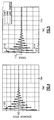
- FIG 4 is a graph showing the effect of the load damper 12 on generator rotational speed.
- a generator rotational speed 100 varies from a desired rotational speed 102.
- the desired rotational speed 102 could be 7,400 revolutions per minute ("RPMs").
- RPMs revolutions per minute
- other desired rotational speeds would be possible.
- the threshold monitor 78 of controller 40 could be configured to only provide load damping if the rotational speed exceeded the predefined rotational speed oscillation threshold.
- what constitutes an acceptable level of torsional oscillation could be application-specific, and thus the speed oscillation threshold could vary between applications.
- FIG. 5 is a graph showing the effect of the load damper 12 on torsional oscillation.
- a shaft speed 110 e.g., torque of shaft 16
- the shaft torque 110 oscillation is not in phase with the rotational speed 100 oscillation of Figure 4 , but leads it by very nearly 90 degrees due to the physics of the second order mechanical torsional oscillations.
- load damping 114 is applied, torsional oscillations decrease until at a time 116 the shaft torque 110 is effectively the same as the load torque 112.
- the load damping 114. is applied only during positive half cycles of the rotational speed 100 oscillation, and is applied properly phased relative to speed oscillations 100 through phase compensation of filter 74, thereby damping the torsional oscillations.
- a ratio of a magnitude of a torque from load damping 114 from the resistive load to a magnitude of shaft torque 110 oscillation of the rotating shaft is approximately 1/10, such that as the shaft torque 110 diminishes the magnitude of applied load damping 114 is also reduced.
- other ratios could be used depending on how fast the torsional oscillations are desired to be damped out, and/or how much power can be safely dissipated by the heat sink 82.
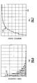
- Figure 6 is a graph showing the power 120 dissipated by the load damper 12. As shown in Figure 6 , as load damping is reduced over time, the amount of power dissipated by the load damper is also reduced. Figure 7 illustrates an amount of energy 124 dissipated by the load damper 12. The amount of dissipated energy 124 corresponds to an area under the power dissipation 120 curve in Figure 6 . As load damping is reduced, the dissipated energy 124 reaches a steady level and eventually stops increasing at approximately a time 126.
- the load damper 12 could be used as a redundant backup for another source of mechanical or electrical load damping.
- the load damper 12 could be configured to act as a backup damper to the electrical load damper described in EP-A-2020744 .
- the load damper 12 and associated controller 40 could be configured to be retrofitted to supplement or replace a mechanical load damper in an existing aircraft.
- resistive loads 52 have been described as corresponding to resistors (see Figs. 3a-b) , it is understood that other loads could be used to provide an active damping function.
- loads could include a resistive anti-ice circuit, a battery charger, and a galley.
- a load could be chosen such that by providing damping, the resistive load would also be providing another useful function (e.g., melting ice, charging a battery, etc.).
- the generator 10 has been described as being three phase
- the damper 12 has been described as having three phase legs 50a-c, it is understood that other quantities of phases could be used.
Landscapes
- Engineering & Computer Science (AREA)
- Power Engineering (AREA)
- Control Of Eletrric Generators (AREA)
Abstract
Description
- This application relates to damping torsional oscillation, and more specifically to an electric load damper for damping torsional oscillation.
- Synchronous generators are used in a variety of applications to convert mechanical energy provided by an engine to alternating current ("AC") electrical energy. One example application for a synchronous generator is a gas turbine engine for an aircraft, in which the generator generates AC electrical energy to operate on-board electrical systems.
- A gas turbine engine may be used to generate mechanical energy that is provided through a gearbox along a shaft to one or more synchronous generators. Due to a multitude of competing mechanical design considerations, the shaft may be relatively long and mechanically compliant. The inertias associated with the engine, the gearbox, the one or more synchronous generators, and other gearbox driven accessories in combination with the mechanical compliance or spring rates of the mechanical drive train, including the generator shaft, may create a distributed mechanical spring-mass system that exhibits torsional oscillation.
- Engine gearboxes may exhibit lightly damped characteristics, resulting in overall negative damping when coupled to a high power generator or generators due to their electromechanical torque characteristics for disturbance frequencies that are within the generator's voltage regulation bandwidth. In certain situations, depending on factors such as generator speed, generator electrical load, and net effective damping in the overall mechanical drive train, the torsional resonance of the spring-mass system involving the generator or generators can lead to large, undesirable torsional oscillations and mechanical failures in the system. Although mechanical damping may be used to offset the negative damping characteristic of the synchronous generator or generators and thus dampen the torsional oscillations in the spring-mass system, mechanical damping requires additional hardware and mechanical components that can increase the weight and cost of a system.
- An electric load damper assembly includes a synchronous generator operable to provide a plurality of phases of electrical output in response to a mechanical input from a rotating shaft. An electric load damper includes a phase leg for each of the plurality of phases. Each phase leg includes a resistive load, a snubber, and at least one solid state switch. The at least one solid state switch is connected in parallel with the snubber. The at least one solid state switch and snubber are collectively connected in series with the resistive load. A controller is operable to receive a signal indicative of a rotational speed oscillation of the synchronous generator, and is operable to selectively reduce a torsional oscillation of the shaft by diverting electrical current from the synchronous generator through the resistive load of each of the plurality of phases in response to the signal exceeding a predefined rotational speed oscillation threshold.
- A method of damping torsional oscillation is also disclosed.
- In another feature, the rotating shaft corresponds to an aircraft gas turbine engine.
- These and other features of the present invention can be best understood from the following specification and drawings, the following of which is a brief description.
-
-
Figure 1 schematically illustrates a gas turbine engine drive schematic for a synchronous generator that utilizes a load damper. -
Figure 2 schematically illustrates a control configuration for the load damper. -
Figure 3a schematically illustrates an example electric load damper. -
Figure 3b schematically illustrates another example second load damper. -
Figure 4 is a graph showing the effect of load damping on generator rotational speed. -
Figure 5 is a graph showing the effect of damping on torsional oscillation. -
Figure 6 is a graph showing the effect of load damping on power dissipation. -
Figure 7 is a graph showing the effect of load damping on energy dissipation. -
Figure 1 schematically illustrates a drive schematic for asynchronous generator 10 that utilizes aload damper 12. An engine/gear box 14 transmits rotating mechanical power along ashaft 16 to thesynchronous generator 10. Thegenerator 10 uses the mechanical power to generate an electrical output to one ormore aircraft loads 20. A generator control unit ("GCU") 22 monitors the output voltage of thegenerator 10 and adjusts the voltage to anexciter generator 30 to maintain a desired output voltage. - The
synchronous generator 10 includes amain generator 26, arotating rectifier assembly 28, theexciter generator 30, and a permanent magnet generator ("PMG") 32. Themain generator 26, exciter 30, andPMG 32 are electrical machines that are either on theshaft 16 or are connected through a gear ratio to theshaft 16. In response to the mechanical power provided by theshaft 16,PMG 32 generates a 3-phase alternating current ("AC") output voltage that thePMG 32 provides to theGCU 22. Circuitry included withinGCU 22 rectifies the three-phase AC voltage to a direct current ("DC") value, and then regulates the DC value to a desired magnitude that is provided as an excitation voltage to exciter 30.GCU 22 regulates the magnitude of the excitation voltage based on monitoring the output three-phase AC voltage generated bymain generator 26. -
Figure 2 illustrates electrical connections of the drive schematic ofFigure 1 in greater detail. Power leads 64a-c connect three-phase electric power fromsynchronous generator 10 to theloads 20 and to theelectrical load damper 12.Voltage sense lines 66 provide voltage signals toGCU 22 for voltage regulation and protection purposes. PMG 32 provides three-phase electric power toGCU 22 through PMG leads 34.GCU 22 converts the three-phase electrical power provided by PMG leads 34 to DC electric power, modulates the level of DC power in response toGCU 22 voltage regulation and protection functions, and returns this DC power to the field terminals of exciter 30 via exciter field leads 36. Exciter 30 supplies three-phase electric output power through exciter leads 68 to rotatingrectifier 28, which in turn provides DC excitation power through generator field leads 70 to the field ofmain generator 26. - At certain rotational speeds, components of the engine 10 (e.g., shaft 16) may experience unacceptable levels of torsional oscillation that exceed a predefined acceptable threshold of torsional oscillation. If such torsional oscillation is not addressed, the torsional oscillation can reduce the life of certain parts (e.g. engine/gearbox 14) or cause those parts to fail.
- A
controller 40 is operable to detect torsional oscillation in the signal 71 from theGCU 22, and is operable to determine if the detected oscillation exceeds a predefined rotational speed oscillation threshold. If thegenerator 10 experiences oscillation, the frequency of the three phases A-C (see leads 64a-c) would vary, as thegenerator 10 rotational speed varies. The varying rotational speed of thegenerator 10 would have a constant portion and an oscillating signal superimposed on the constant portion. The signal 71 corresponds to the extracted oscillating signal of thegenerator 10 rotational speed signal. - The
controller 40 includes afilter 74, a half-wave rectifier 76, athreshold monitor 78, and agate driver 80. Thefilter 74 is operable to change a gain or phase of the input signal 71 from theGCU 22. The half-wave rectifier 76 removes a negative portion of the input signal 71, leaving only the positive portion. By using filter 74 (e.g., a high pass filter) and half-wave rectifier 76 to reject a steady or DC frequency, thethreshold monitor 78 could use this filtered frequency signal to detect generator speed oscillations indicative of torsional oscillations. In one example, thethreshold monitor 78 verifies (1) that a torsional oscillation exceeds the predefined acceptable threshold of torsional oscillation such that active damping is needed, and (2) that theload damper 12 is still capable of absorbing additional energy without thermally damaging theresistive load 52 and without causing theresistive load 52 to fail. If both of these conditions are true, thecontroller 40commands gate driver 80 to divert electrical current from thegenerator 26 through a plurality of resistive loads (seeFigs. 3a-b) withindamper 12 to damp the torsional oscillation. By usingfilter 74 to establish an appropriate gain and phase compensation, thecontroller 40 can establish a proper phase relationship between the duty cycle of theswitches 56, 58 and the sensed rotor speed oscillations ofgenerator 10 such that positive mechanical damping is provided and torsional oscillations are damped out. In one example thefilter 74 is selected such that theload damper 12 is broadband over a wide frequency range (e.g. 20-40 Hz), and as such theload damper 12 could be applied to a variety of different gas turbine engine gearbox applications. -
Figure 3a schematically illustrates anexample damper 12a that may be used to damp torsional oscillation. Theload damper 12a includes a plurality of phase legs 50, each corresponding to one of a plurality of phases of AC current (see leads 64a-c). Referring tophase leg 50a, the phase leg includes aresistive load 52, asnubber 54, a first solid state switch 56 and a secondsolid state switch 58. Thesnubber 54 is operable to diminish electromagnetic interference ("EMI"). Thesolid state switches 56, 58 are connected in parallel with thesnubber 54. Thesnubber 54 and switches 56, 58 are collectively connected in series with theresistive load 52. Theswitches 56, 58 are oriented to prevent a flow of current when in an OFF state. In one example ofFigs. 3a-b , theswitches 56, 58 are MOSFETs, and a drain of the switch 56 is connected in series to a drain of thesecond switch 58 to prevent a flow of current when in the OFF state. However, other switches could be used, such as IGBTs with diodes, or other solid state switches. - The
gate driver 80 controls eachswitch 56, 58 to turn ON or OFF. When thegate driver 80 turns switches 56, 58 ON, current is diverted from thesynchronous generator 10 through thedamper 12. When thegate driver 80 turns switches 56, 58 OFF, no current flows through the resistive loads 52. In one example, theswitches 56, 58 of eachphase leg 50a-c are connected to asingle gate driver 80 that turns theswitches 56, 58 of each phase leg ON or OFF simultaneously. Of course,multiple gate drivers 80 could be used, and different switch timing could also be used. The plurality of load damper phase legs 50 and one or more of the gate drivers 50 are configured to minimize the deleterious effects of harmonics on the electrical power quality of the electric power system. These harmonics can arise from variable duty cycle switching of the resistive loads 52. - In the example of the
damper 12a, eachresistive load 52 is connected to acommon node 62, such that thephase legs 50a-c are Y-connected. In the example of thedamper 12b ofFigure 3b , however, thephase legs 50d-f are connected such that eachresistive load 52 at an output of a phase leg 50 is connected to an input of a subsequent phase leg 50, and such that thephase legs 50d-f are delta-connected. Thus, inFigure 3b ,resistive load 52 ofphase leg 50d is connected to an input ofphase leg 50e, etc. - The
controller 40 is operable to control a duty cycle of the resistive loads 52. The term duty cycle refers to an amount of time that theswitches 56, 58 controlling current to eachresistive load 52 are ON (e.g. duty cycle of "0" means switches 56, 58 are always OFF, duty cycle of "1" means switches 56, 58 are always ON). By diverting electrical current from thesynchronous generator 10 through theresistive loads 52, thecontroller 40 can dynamically modify the duty cycle of theswitches 56, 58 controlling current to theresistive loads 52 such that the torque associated with the generator 10 (e.g., torque of shaft 16) is selectively varied. The amount of damping provided by theresistive loads 52 is proportional to the duty cycle of theswitches 56, 58. By selectively controlling theresistive loads 52 to vary torque in proper phase relationship to the generator speed oscillations, theload damper 12 provides active, positive damping that dampens or reduces the torsional oscillations in thegenerator 10. - The
controller 40 andresistive loads 52 are configured to provide half-cycle damping. That is, theswitches 56, 58 controlling current to theresistive loads 52 are only turned ON during a positive half cycle of the signal 71. Thus, during periods of time when the sensed rotational speed oscillations are positive, theswitches 56, 58 controlling current to theresistive loads 52 may be turned ON and thus may have a duty cycle that may vary from 0 (no damping) to 1 (full damping). During periods of time when the sensed rotational speed oscillations are negative, theswitches 56, 58 controlling current to theresistive loads 52 are OFF and have a duty cycle of zero. For normal operation with a low level of oscillations below the predefined rotational speed oscillation threshold, the duty cycle of theswitches 56, 58 would be zero or very nearly zero. That is, theswitches 56, 58 would only be turned ON for a small portion of a positive half-cycle, if at all. For conditions with a significant level of oscillations present in the signal indicative of speed oscillations (exceeding the predefined rotational speed oscillation threshold), the duty cycle of theswitches 56, 58 could be increased in phase with the sensed rotational speed oscillations during periods of time when the sensed speed oscillations are positive or the actual generator speed is transiently above a short-term average generator speed. Thus, during periods of increased oscillations, theswitches 56, 58 could have a higher duty cycle such that theswitches 56, 58 are turned ON for a greater portion of the positive half-cycle. - A
heat sink 82 removes heat from theresistive loads 52 to prevent theresistive loads 52 from experiencing thermal failure, as the electric power dissipated in theresistive loads 52 ends up as heat. Theheat sink 82 may correspond, for example, to a forced or natural convective air cooling or a circulating liquid cooling loop. Of course,other heat sinks 82 could be used. -
Figure 4 is a graph showing the effect of theload damper 12 on generator rotational speed. As shown inFigure 4 , a generatorrotational speed 100 varies from a desiredrotational speed 102. In one example the desiredrotational speed 102 could be 7,400 revolutions per minute ("RPMs"). Of course, other desired rotational speeds would be possible. As load damping is applied, oscillations inrotational speed 100 reduce until a point intime 104 when the rotational speed is effectively operating in a steady state. The threshold monitor 78 ofcontroller 40 could be configured to only provide load damping if the rotational speed exceeded the predefined rotational speed oscillation threshold. Of course, what constitutes an acceptable level of torsional oscillation could be application-specific, and thus the speed oscillation threshold could vary between applications. -
Figure 5 is a graph showing the effect of theload damper 12 on torsional oscillation. As shown inFigure 5 , a shaft speed 110 (e.g., torque of shaft 16) exhibits torsional oscillation and differs from a desiredload torque 112. Theshaft torque 110 oscillation is not in phase with therotational speed 100 oscillation ofFigure 4 , but leads it by very nearly 90 degrees due to the physics of the second order mechanical torsional oscillations. As load damping 114 is applied, torsional oscillations decrease until at atime 116 theshaft torque 110 is effectively the same as theload torque 112. The load damping 114. is applied only during positive half cycles of therotational speed 100 oscillation, and is applied properly phased relative to speedoscillations 100 through phase compensation offilter 74, thereby damping the torsional oscillations. - Also, in the example of
Fig. 5 , a ratio of a magnitude of a torque from load damping 114 from the resistive load to a magnitude ofshaft torque 110 oscillation of the rotating shaft is approximately 1/10, such that as theshaft torque 110 diminishes the magnitude of applied load damping 114 is also reduced. Of course, other ratios could be used depending on how fast the torsional oscillations are desired to be damped out, and/or how much power can be safely dissipated by theheat sink 82. -
Figure 6 is a graph showing the power 120 dissipated by theload damper 12. As shown inFigure 6 , as load damping is reduced over time, the amount of power dissipated by the load damper is also reduced.Figure 7 illustrates an amount ofenergy 124 dissipated by theload damper 12. The amount of dissipatedenergy 124 corresponds to an area under the power dissipation 120 curve inFigure 6 . As load damping is reduced, the dissipatedenergy 124 reaches a steady level and eventually stops increasing at approximately atime 126. - In some applications (e.g., aircraft operation) it is possible that damping would be critical, and that redundancy would be required to meet reliability requirements. In such an application, the
load damper 12 could be used as a redundant backup for another source of mechanical or electrical load damping. For example, theload damper 12 could be configured to act as a backup damper to the electrical load damper described inEP-A-2020744 . In one example, theload damper 12 and associatedcontroller 40 could be configured to be retrofitted to supplement or replace a mechanical load damper in an existing aircraft. - Although the damping,
resistive loads 52 have been described as corresponding to resistors (seeFigs. 3a-b) , it is understood that other loads could be used to provide an active damping function. Using the example of an aircraft, other example loads could include a resistive anti-ice circuit, a battery charger, and a galley. Thus, a load could be chosen such that by providing damping, the resistive load would also be providing another useful function (e.g., melting ice, charging a battery, etc.). Also, although thegenerator 10 has been described as being three phase, and thedamper 12 has been described as having threephase legs 50a-c, it is understood that other quantities of phases could be used. - Although a preferred embodiment of this invention has been disclosed, a worker of ordinary skill in this art would recognize that certain modifications would come within the scope of this invention. For that reason, the following claims should be studied to determine the true scope and content of this invention.
Claims (15)
- An electric load damper assembly, comprising:a synchronous generator (10) operable to provide a plurality of phases (A-C) of electrical output in response to a mechanical input from a rotating shaft (16);an electric load damper (12) including a phase leg (50a-f) for each of the plurality of phases, each phase leg comprising:a resistive load (52);a snubber (54); andat least one solid state switch (56, 58) connected in parallel with the snubber, the at least one solid state switch and snubber being collectively connected in series with the resistive load; anda controller (40) operable to receive a signal indicative of a rotational speed oscillation of the synchronous generator, and operable to selectively reduce a torsional oscillation of the shaft by diverting electrical current from the synchronous generator through the resistive load of each of the plurality of phases in response to the signal exceeding a predefined rotational speed oscillation threshold.
- The assembly of claim 1, wherein the resistive loads (52) for each of the plurality of phases are connected to a common node (62), and an input of each phase leg (50a-f) of the electric load damper is connected to one of the plurality of phases (A-C), such that the phase legs are Y-connected.
- The assembly of claim 1, wherein each of the plurality of phases (A-C) of current is connected to an input of a first phase leg of the electric load damper and an output of a second phase leg of the electric load damper, such that the phase legs are delta-connected.
- The assembly of claim 1, 2 or 3, wherein the at least one solid state switch (56, 58) includes a first MOSFET (56) and a second MOSFET (58), the first MOSFET and the second MOSFET being oriented to prevent a flow of current when in an OFF state.
- The assembly of claim 4, wherein a drain of the first MOSFET (56) is connected in series to a drain of the second MOSFET (58).
- The assembly of any preceding claim, wherein the controller (40) diverts electrical current from the synchronous generator (10) through each resistive load (52) by turning ON the at least one solid state switch (56, 58) for each of the phase legs (50a-f).
- The assembly of any preceding claim, wherein the controller (40) only turns the at least one solid state switch (56, 58) ON during positive half cycles of the signal; preferably wherein the controller stops turning the at least one solid state switch ON during positive half cycles of the signal when the oscillations no longer exceed the predefined rotational speed oscillation threshold.
- The assembly of any preceding claim, further comprising a heat sink (82) operable to dissipate heat generated by each resistive load (52).
- The assembly of any preceding claim, further comprising a generator control unit (22) operable to provide excitation energy to the synchronous generator (10), and operable to provide the signal indicative of a rotational speed oscillation of the synchronous generator to the controller (40).
- An aircraft torsional oscillation damping system, comprising:a gas turbine engine having at least one rotating shaft (16); andat least one electric load damper assembly as claimed in any preceding claim, the at least one synchronous generator being coupled to said at least one rotating shaft.
- The assembly of claim 10, wherein the electric load damper and the controller (40) are configured to supplement or replace a mechanical load damper in an aircraft.
- A method of damping torsional oscillation, comprising:receiving a signal indicative of a rotational speed oscillation of a synchronous generator (10), the synchronous generator being driven by a rotating shaft (16); anddiverting electrical current from each of a plurality of phases (A-C) of the synchronous generator through a plurality of resistive loads (52), each resistive load corresponding to one of the plurality of phases to reduce a torsional oscillation of the shaft in response to the oscillations exceeding a predefined rotational speed oscillation threshold.
- The method of claim 12, wherein said step of diverting electrical current is selectively repeated until the oscillations are within the predefined rotational speed oscillation threshold.
- The method of claim 12 or 13, wherein said step of diverting electrical current is only performed during positive half cycles of the signal.
- The method of claim 12, 13 or 14, wherein said step of diverting electrical current is only performed in response to a determination that the resistive load has the capacity to absorb additional energy.
Applications Claiming Priority (1)
| Application Number | Priority Date | Filing Date | Title |
|---|---|---|---|
| US12/620,625 US8217630B2 (en) | 2009-11-18 | 2009-11-18 | Electric load damper for damping torsional oscillation |
Publications (3)
| Publication Number | Publication Date |
|---|---|
| EP2325999A2 true EP2325999A2 (en) | 2011-05-25 |
| EP2325999A3 EP2325999A3 (en) | 2012-01-25 |
| EP2325999B1 EP2325999B1 (en) | 2018-09-12 |
Family
ID=43770641
Family Applications (1)
| Application Number | Title | Priority Date | Filing Date |
|---|---|---|---|
| EP10251931.1A Active EP2325999B1 (en) | 2009-11-18 | 2010-11-15 | Electric load damper for damping torsional oscillation |
Country Status (2)
| Country | Link |
|---|---|
| US (1) | US8217630B2 (en) |
| EP (1) | EP2325999B1 (en) |
Cited By (5)
| Publication number | Priority date | Publication date | Assignee | Title |
|---|---|---|---|---|
| CN103560731A (en) * | 2013-10-29 | 2014-02-05 | 北京踏行天际科技发展有限公司 | Control circuit enabling resistance of electric generator to be adjusted according to driving force and adjusting method |
| WO2014209542A1 (en) * | 2013-06-25 | 2014-12-31 | Siemens Energy, Inc. | Using static excitation system to reduce the amplitude of torsional oscillations due to fluctuating industrial loads |
| EP3159573A1 (en) * | 2015-10-23 | 2017-04-26 | General Electric Company | Torsional damping for gas turbine engines |
| US11300059B2 (en) | 2018-11-09 | 2022-04-12 | Rolls-Royce Plc | Shaft resonance control |
| US11346243B2 (en) | 2015-10-23 | 2022-05-31 | General Electric Company | Torsional damping for gas turbine engines |
Families Citing this family (14)
| Publication number | Priority date | Publication date | Assignee | Title |
|---|---|---|---|---|
| DE102012010420A1 (en) * | 2012-05-29 | 2013-12-05 | Robert Bosch Gmbh | Method for damping torsional vibrations in a driveline component |
| CN103051266A (en) * | 2013-01-18 | 2013-04-17 | 上海电机学院 | Method and device for generating electrical failure of wind driven generator rotor |
| US9143070B2 (en) * | 2013-08-02 | 2015-09-22 | Hamilton Sundstrand Corporation | Systems and methods for controlling torsional oscillation in wound field synchronous generator machines |
| US9285386B2 (en) | 2013-12-06 | 2016-03-15 | Rosemount Aerospace Inc. | Inductive rotational speed sensors |
| US9771823B2 (en) * | 2014-06-26 | 2017-09-26 | General Electric Company | Power generation system control following transient grid event |
| US10205414B2 (en) * | 2016-05-24 | 2019-02-12 | General Electric Company | Systems and methods for adjusting operations of a gas turbine following a transient event |
| US10693403B2 (en) * | 2017-03-23 | 2020-06-23 | Ge Aviation Systems Llc | Torsional damping for generators |
| US11097849B2 (en) | 2018-09-10 | 2021-08-24 | General Electric Company | Aircraft having an aft engine |
| EP3683471B1 (en) | 2019-01-15 | 2024-03-06 | ABB Schweiz AG | Damping torsional oscillations in a drive system |
| US11539316B2 (en) | 2019-07-30 | 2022-12-27 | General Electric Company | Active stability control of compression systems utilizing electric machines |
| CN112861328B (en) * | 2021-01-22 | 2022-08-30 | 东北电力大学 | Generator damping evaluation device and method based on random response signals |
| EP4305653A1 (en) | 2021-03-12 | 2024-01-17 | Essex Industries, Inc. | Rocker switch |
| EP4309200A1 (en) | 2021-03-15 | 2024-01-24 | Essex Industries, Inc. | Five-position switch |
| CN113890058B (en) * | 2021-09-27 | 2023-07-21 | 国网天津市电力公司 | A Method for Analyzing Damping Characteristics of Synchronous Motor System |
Citations (1)
| Publication number | Priority date | Publication date | Assignee | Title |
|---|---|---|---|---|
| EP2020744A2 (en) | 2007-07-02 | 2009-02-04 | Hamilton Sundstrand Corporation | Active damping for synchronous generator torsional oscillations |
Family Cites Families (27)
| Publication number | Priority date | Publication date | Assignee | Title |
|---|---|---|---|---|
| NL58578C (en) * | 1938-07-19 | 1900-01-01 | ||
| US3573578A (en) * | 1968-06-19 | 1971-04-06 | Fukuo Shibata | Electric machine arrangements including electric rotating machines |
| US3611831A (en) * | 1969-12-03 | 1971-10-12 | Physics Int Co | Torsional vibration damper |
| US3999115A (en) * | 1974-05-02 | 1976-12-21 | Westinghouse Electric Corporation | Dynamic stabilizer for synchronous machines having torsional oscillations and method |
| US4292531A (en) * | 1977-12-27 | 1981-09-29 | General Electric Company | Electrical propulsion process and system for a traction vehicle with an on-board source of power |
| US4330829A (en) * | 1979-01-24 | 1982-05-18 | United Technologies Corporation | Helicopter flight stability control induced oscillation suppression |
| US4302715A (en) * | 1979-06-15 | 1981-11-24 | Westinghouse Electric Corp. | Dynamic parallel inductive stabilizer for synchronous machines having torsional oscillations |
| US4311253A (en) * | 1979-09-14 | 1982-01-19 | Westinghouse Electric Corp. | Low loss stabilizer |
| US4407161A (en) * | 1982-02-11 | 1983-10-04 | United Technologies Corporation | Fluid jet displacement detector |
| DE4007697A1 (en) * | 1990-03-10 | 1991-09-12 | Fichtel & Sachs Ag | Torsion vibration damper in clutch disc - has viscous fluid inside housing for displacement outwards during torque impingement |
| US5198745A (en) * | 1991-08-08 | 1993-03-30 | Electric Power Research Institute | Dynamic braking resistor system |
| EP0797022B1 (en) * | 1996-03-22 | 2002-02-06 | Patentverwertungsgesellschaft Rohs Voigt mbH | Torsional vibration damper |
| EP0856682B1 (en) * | 1997-01-31 | 2004-04-14 | Rohs-Voigt Patentverwertungsgesellschaft mbH | Torsional vibration damper |
| US5994859A (en) * | 1997-04-30 | 1999-11-30 | Ford Motor Company | Torsional oscillation compensation in the drivetrain of a motor vehicle |
| US5841254A (en) * | 1997-07-09 | 1998-11-24 | General Electric Company | Torque maximization and vibration control for AC locomotives |
| DE19859622A1 (en) * | 1998-12-23 | 2000-07-06 | Braun Gmbh | Drive device for oscillating electrical products for personal use, in particular dry shavers |
| US6163121A (en) * | 1999-01-29 | 2000-12-19 | General Electric Company | Torque maximization and vibration control for AC locomotives |
| US6290620B1 (en) * | 1999-06-25 | 2001-09-18 | Hamilton Sundstrand Corporation | Continuously variable transmission with control arrangement and method for reducing impact of shock load |
| DE10035521B4 (en) * | 2000-07-21 | 2006-04-20 | Zf Sachs Ag | Method and device for reducing load oscillations in the drive train of a motor vehicle |
| CA2592456C (en) * | 2004-12-23 | 2015-01-06 | Alstom Technology Ltd. | Method for the operation of a pressure accumulator plant, and pressure accumulator plant |
| US7479091B2 (en) * | 2005-08-15 | 2009-01-20 | Tai-Her Yang | Engine running at fixed speed incorporated controllable transmission power system |
| DE102005040778A1 (en) * | 2005-08-29 | 2007-03-08 | Robert Bosch Gmbh | Method for limiting setpoint torques in engine control |
| US7423411B2 (en) * | 2006-05-05 | 2008-09-09 | General Electric Company | Resistive torsional mode damping system and method |
| US7948197B2 (en) * | 2007-02-27 | 2011-05-24 | Peabody Energy Corporation | Controlling torsional shaft oscillation |
| US8172720B2 (en) * | 2007-03-05 | 2012-05-08 | Tai-Her Yang | Differential generation power distribution system |
| US8004252B2 (en) * | 2007-06-29 | 2011-08-23 | General Electric Company | Power system stabilizer and method |
| JP2009031642A (en) * | 2007-07-30 | 2009-02-12 | Canon Inc | Oscillator device, optical deflector, and image forming apparatus using the same |
-
2009
- 2009-11-18 US US12/620,625 patent/US8217630B2/en active Active
-
2010
- 2010-11-15 EP EP10251931.1A patent/EP2325999B1/en active Active
Patent Citations (1)
| Publication number | Priority date | Publication date | Assignee | Title |
|---|---|---|---|---|
| EP2020744A2 (en) | 2007-07-02 | 2009-02-04 | Hamilton Sundstrand Corporation | Active damping for synchronous generator torsional oscillations |
Cited By (10)
| Publication number | Priority date | Publication date | Assignee | Title |
|---|---|---|---|---|
| WO2014209542A1 (en) * | 2013-06-25 | 2014-12-31 | Siemens Energy, Inc. | Using static excitation system to reduce the amplitude of torsional oscillations due to fluctuating industrial loads |
| CN105393449A (en) * | 2013-06-25 | 2016-03-09 | 西门子能源公司 | Using static excitation system to reduce the amplitude of torsional oscillations due to fluctuating industrial loads |
| CN103560731A (en) * | 2013-10-29 | 2014-02-05 | 北京踏行天际科技发展有限公司 | Control circuit enabling resistance of electric generator to be adjusted according to driving force and adjusting method |
| CN103560731B (en) * | 2013-10-29 | 2016-08-17 | 北京踏行天际科技发展有限公司 | Control circuit and the control method of electromotor resistance is adjusted according to driving force size |
| EP3159573A1 (en) * | 2015-10-23 | 2017-04-26 | General Electric Company | Torsional damping for gas turbine engines |
| JP2017096258A (en) * | 2015-10-23 | 2017-06-01 | ゼネラル・エレクトリック・カンパニイ | Torsional damping for gas turbine engines |
| US11346243B2 (en) | 2015-10-23 | 2022-05-31 | General Electric Company | Torsional damping for gas turbine engines |
| US11802492B2 (en) | 2015-10-23 | 2023-10-31 | General Electric Company | Torsional damping for gas turbine engines |
| US12372006B2 (en) | 2015-10-23 | 2025-07-29 | General Electric Company | Torsional damping for gas turbine engines |
| US11300059B2 (en) | 2018-11-09 | 2022-04-12 | Rolls-Royce Plc | Shaft resonance control |
Also Published As
| Publication number | Publication date |
|---|---|
| US8217630B2 (en) | 2012-07-10 |
| EP2325999A3 (en) | 2012-01-25 |
| EP2325999B1 (en) | 2018-09-12 |
| US20110115444A1 (en) | 2011-05-19 |
Similar Documents
| Publication | Publication Date | Title |
|---|---|---|
| EP2325999B1 (en) | Electric load damper for damping torsional oscillation | |
| US8981584B2 (en) | Generator torque control methods | |
| ES2914580T3 (en) | Procedure and device for virtual mass inertia control for power plants with double feed asynchronous machine | |
| JP6306804B2 (en) | Gas turbine power generation system and control system used therefor | |
| US7173399B2 (en) | Integrated torsional mode damping system and method | |
| JP4886585B2 (en) | Resistive torsional mode vibration isolation system and method | |
| US8415914B2 (en) | Motor drive load damping | |
| US9444391B2 (en) | Protective module and method against torque peaks between a motor and an electric machine | |
| CN101335457B (en) | Power system stabilizer and method | |
| US10554160B2 (en) | System and method for operating a pumped storage power plant with a double fed induction machine | |
| KR20160081976A (en) | Turbulence Compensation System and Method for Turbine Generators | |
| KR102588198B1 (en) | A wind turbine pitch cabinet temperature control system | |
| EP2045910B1 (en) | Starter/generator system with control to address a voltage rise | |
| US7642664B1 (en) | Transient energy systems and methods for use of the same | |
| EP1764908A1 (en) | Electrical power stabilisation | |
| US8847560B2 (en) | Aircraft power supply circuit including an asynchronous machine | |
| KR20160082594A (en) | Turbulence Protection System and Method for Turbine Generators | |
| Song-Manguelle et al. | Modeling of torsional resonances for multi-megawatt drives design | |
| US12068645B2 (en) | System configured to deliver a polyphase current of constant frequency from a synchronous generator | |
| KR20100134600A (en) | Vibration damping device | |
| EP2075905A1 (en) | Method and system for maintaining magnetisation of a wind turbine generator during power grid faults | |
| KR20170125091A (en) | How to Reduce the Noise of an Electric Motor | |
| Shan et al. | Synchronous Generator System with Enhanced Capabilities for Low Voltage Fault Ride Through |
Legal Events
| Date | Code | Title | Description |
|---|---|---|---|
| PUAI | Public reference made under article 153(3) epc to a published international application that has entered the european phase |
Free format text: ORIGINAL CODE: 0009012 |
|
| AK | Designated contracting states |
Kind code of ref document: A2 Designated state(s): AL AT BE BG CH CY CZ DE DK EE ES FI FR GB GR HR HU IE IS IT LI LT LU LV MC MK MT NL NO PL PT RO RS SE SI SK SM TR |
|
| AX | Request for extension of the european patent |
Extension state: BA ME |
|
| PUAL | Search report despatched |
Free format text: ORIGINAL CODE: 0009013 |
|
| AK | Designated contracting states |
Kind code of ref document: A3 Designated state(s): AL AT BE BG CH CY CZ DE DK EE ES FI FR GB GR HR HU IE IS IT LI LT LU LV MC MK MT NL NO PL PT RO RS SE SI SK SM TR |
|
| AX | Request for extension of the european patent |
Extension state: BA ME |
|
| RIC1 | Information provided on ipc code assigned before grant |
Ipc: H02P 9/16 20060101ALI20111220BHEP Ipc: H02P 9/30 20060101ALI20111220BHEP Ipc: H02P 9/10 20060101AFI20111220BHEP Ipc: H02J 3/24 20060101ALI20111220BHEP |
|
| 17P | Request for examination filed |
Effective date: 20120725 |
|
| 17Q | First examination report despatched |
Effective date: 20160923 |
|
| STAA | Information on the status of an ep patent application or granted ep patent |
Free format text: STATUS: EXAMINATION IS IN PROGRESS |
|
| GRAP | Despatch of communication of intention to grant a patent |
Free format text: ORIGINAL CODE: EPIDOSNIGR1 |
|
| STAA | Information on the status of an ep patent application or granted ep patent |
Free format text: STATUS: GRANT OF PATENT IS INTENDED |
|
| INTG | Intention to grant announced |
Effective date: 20180328 |
|
| GRAS | Grant fee paid |
Free format text: ORIGINAL CODE: EPIDOSNIGR3 |
|
| GRAA | (expected) grant |
Free format text: ORIGINAL CODE: 0009210 |
|
| STAA | Information on the status of an ep patent application or granted ep patent |
Free format text: STATUS: THE PATENT HAS BEEN GRANTED |
|
| AK | Designated contracting states |
Kind code of ref document: B1 Designated state(s): AL AT BE BG CH CY CZ DE DK EE ES FI FR GB GR HR HU IE IS IT LI LT LU LV MC MK MT NL NO PL PT RO RS SE SI SK SM TR |
|
| REG | Reference to a national code |
Ref country code: GB Ref legal event code: FG4D |
|
| REG | Reference to a national code |
Ref country code: CH Ref legal event code: EP |
|
| REG | Reference to a national code |
Ref country code: IE Ref legal event code: FG4D |
|
| REG | Reference to a national code |
Ref country code: DE Ref legal event code: R096 Ref document number: 602010053493 Country of ref document: DE |
|
| REG | Reference to a national code |
Ref country code: AT Ref legal event code: REF Ref document number: 1041779 Country of ref document: AT Kind code of ref document: T Effective date: 20181015 |
|
| REG | Reference to a national code |
Ref country code: FR Ref legal event code: PLFP Year of fee payment: 9 |
|
| REG | Reference to a national code |
Ref country code: NL Ref legal event code: MP Effective date: 20180912 |
|
| REG | Reference to a national code |
Ref country code: LT Ref legal event code: MG4D |
|
| PG25 | Lapsed in a contracting state [announced via postgrant information from national office to epo] |
Ref country code: FI Free format text: LAPSE BECAUSE OF FAILURE TO SUBMIT A TRANSLATION OF THE DESCRIPTION OR TO PAY THE FEE WITHIN THE PRESCRIBED TIME-LIMIT Effective date: 20180912 Ref country code: RS Free format text: LAPSE BECAUSE OF FAILURE TO SUBMIT A TRANSLATION OF THE DESCRIPTION OR TO PAY THE FEE WITHIN THE PRESCRIBED TIME-LIMIT Effective date: 20180912 Ref country code: GR Free format text: LAPSE BECAUSE OF FAILURE TO SUBMIT A TRANSLATION OF THE DESCRIPTION OR TO PAY THE FEE WITHIN THE PRESCRIBED TIME-LIMIT Effective date: 20181213 Ref country code: NO Free format text: LAPSE BECAUSE OF FAILURE TO SUBMIT A TRANSLATION OF THE DESCRIPTION OR TO PAY THE FEE WITHIN THE PRESCRIBED TIME-LIMIT Effective date: 20181212 Ref country code: SE Free format text: LAPSE BECAUSE OF FAILURE TO SUBMIT A TRANSLATION OF THE DESCRIPTION OR TO PAY THE FEE WITHIN THE PRESCRIBED TIME-LIMIT Effective date: 20180912 Ref country code: BG Free format text: LAPSE BECAUSE OF FAILURE TO SUBMIT A TRANSLATION OF THE DESCRIPTION OR TO PAY THE FEE WITHIN THE PRESCRIBED TIME-LIMIT Effective date: 20181212 Ref country code: LT Free format text: LAPSE BECAUSE OF FAILURE TO SUBMIT A TRANSLATION OF THE DESCRIPTION OR TO PAY THE FEE WITHIN THE PRESCRIBED TIME-LIMIT Effective date: 20180912 |
|
| PG25 | Lapsed in a contracting state [announced via postgrant information from national office to epo] |
Ref country code: HR Free format text: LAPSE BECAUSE OF FAILURE TO SUBMIT A TRANSLATION OF THE DESCRIPTION OR TO PAY THE FEE WITHIN THE PRESCRIBED TIME-LIMIT Effective date: 20180912 Ref country code: LV Free format text: LAPSE BECAUSE OF FAILURE TO SUBMIT A TRANSLATION OF THE DESCRIPTION OR TO PAY THE FEE WITHIN THE PRESCRIBED TIME-LIMIT Effective date: 20180912 Ref country code: AL Free format text: LAPSE BECAUSE OF FAILURE TO SUBMIT A TRANSLATION OF THE DESCRIPTION OR TO PAY THE FEE WITHIN THE PRESCRIBED TIME-LIMIT Effective date: 20180912 Ref country code: ES Free format text: LAPSE BECAUSE OF FAILURE TO SUBMIT A TRANSLATION OF THE DESCRIPTION OR TO PAY THE FEE WITHIN THE PRESCRIBED TIME-LIMIT Effective date: 20180912 |
|
| REG | Reference to a national code |
Ref country code: AT Ref legal event code: MK05 Ref document number: 1041779 Country of ref document: AT Kind code of ref document: T Effective date: 20180912 |
|
| PG25 | Lapsed in a contracting state [announced via postgrant information from national office to epo] |
Ref country code: CZ Free format text: LAPSE BECAUSE OF FAILURE TO SUBMIT A TRANSLATION OF THE DESCRIPTION OR TO PAY THE FEE WITHIN THE PRESCRIBED TIME-LIMIT Effective date: 20180912 Ref country code: IS Free format text: LAPSE BECAUSE OF FAILURE TO SUBMIT A TRANSLATION OF THE DESCRIPTION OR TO PAY THE FEE WITHIN THE PRESCRIBED TIME-LIMIT Effective date: 20190112 Ref country code: RO Free format text: LAPSE BECAUSE OF FAILURE TO SUBMIT A TRANSLATION OF THE DESCRIPTION OR TO PAY THE FEE WITHIN THE PRESCRIBED TIME-LIMIT Effective date: 20180912 Ref country code: PL Free format text: LAPSE BECAUSE OF FAILURE TO SUBMIT A TRANSLATION OF THE DESCRIPTION OR TO PAY THE FEE WITHIN THE PRESCRIBED TIME-LIMIT Effective date: 20180912 Ref country code: EE Free format text: LAPSE BECAUSE OF FAILURE TO SUBMIT A TRANSLATION OF THE DESCRIPTION OR TO PAY THE FEE WITHIN THE PRESCRIBED TIME-LIMIT Effective date: 20180912 Ref country code: NL Free format text: LAPSE BECAUSE OF FAILURE TO SUBMIT A TRANSLATION OF THE DESCRIPTION OR TO PAY THE FEE WITHIN THE PRESCRIBED TIME-LIMIT Effective date: 20180912 Ref country code: IT Free format text: LAPSE BECAUSE OF FAILURE TO SUBMIT A TRANSLATION OF THE DESCRIPTION OR TO PAY THE FEE WITHIN THE PRESCRIBED TIME-LIMIT Effective date: 20180912 Ref country code: AT Free format text: LAPSE BECAUSE OF FAILURE TO SUBMIT A TRANSLATION OF THE DESCRIPTION OR TO PAY THE FEE WITHIN THE PRESCRIBED TIME-LIMIT Effective date: 20180912 |
|
| PG25 | Lapsed in a contracting state [announced via postgrant information from national office to epo] |
Ref country code: SM Free format text: LAPSE BECAUSE OF FAILURE TO SUBMIT A TRANSLATION OF THE DESCRIPTION OR TO PAY THE FEE WITHIN THE PRESCRIBED TIME-LIMIT Effective date: 20180912 Ref country code: SK Free format text: LAPSE BECAUSE OF FAILURE TO SUBMIT A TRANSLATION OF THE DESCRIPTION OR TO PAY THE FEE WITHIN THE PRESCRIBED TIME-LIMIT Effective date: 20180912 Ref country code: PT Free format text: LAPSE BECAUSE OF FAILURE TO SUBMIT A TRANSLATION OF THE DESCRIPTION OR TO PAY THE FEE WITHIN THE PRESCRIBED TIME-LIMIT Effective date: 20190112 |
|
| REG | Reference to a national code |
Ref country code: DE Ref legal event code: R119 Ref document number: 602010053493 Country of ref document: DE |
|
| REG | Reference to a national code |
Ref country code: CH Ref legal event code: PL |
|
| PLBE | No opposition filed within time limit |
Free format text: ORIGINAL CODE: 0009261 |
|
| STAA | Information on the status of an ep patent application or granted ep patent |
Free format text: STATUS: NO OPPOSITION FILED WITHIN TIME LIMIT |
|
| PG25 | Lapsed in a contracting state [announced via postgrant information from national office to epo] |
Ref country code: MC Free format text: LAPSE BECAUSE OF FAILURE TO SUBMIT A TRANSLATION OF THE DESCRIPTION OR TO PAY THE FEE WITHIN THE PRESCRIBED TIME-LIMIT Effective date: 20180912 Ref country code: DK Free format text: LAPSE BECAUSE OF FAILURE TO SUBMIT A TRANSLATION OF THE DESCRIPTION OR TO PAY THE FEE WITHIN THE PRESCRIBED TIME-LIMIT Effective date: 20180912 Ref country code: LU Free format text: LAPSE BECAUSE OF NON-PAYMENT OF DUE FEES Effective date: 20181115 |
|
| REG | Reference to a national code |
Ref country code: BE Ref legal event code: MM Effective date: 20181130 |
|
| 26N | No opposition filed |
Effective date: 20190613 |
|
| REG | Reference to a national code |
Ref country code: IE Ref legal event code: MM4A |
|
| PG25 | Lapsed in a contracting state [announced via postgrant information from national office to epo] |
Ref country code: CH Free format text: LAPSE BECAUSE OF NON-PAYMENT OF DUE FEES Effective date: 20181130 Ref country code: SI Free format text: LAPSE BECAUSE OF FAILURE TO SUBMIT A TRANSLATION OF THE DESCRIPTION OR TO PAY THE FEE WITHIN THE PRESCRIBED TIME-LIMIT Effective date: 20180912 Ref country code: LI Free format text: LAPSE BECAUSE OF NON-PAYMENT OF DUE FEES Effective date: 20181130 |
|
| PG25 | Lapsed in a contracting state [announced via postgrant information from national office to epo] |
Ref country code: DE Free format text: LAPSE BECAUSE OF NON-PAYMENT OF DUE FEES Effective date: 20190601 Ref country code: IE Free format text: LAPSE BECAUSE OF NON-PAYMENT OF DUE FEES Effective date: 20181115 |
|
| PG25 | Lapsed in a contracting state [announced via postgrant information from national office to epo] |
Ref country code: BE Free format text: LAPSE BECAUSE OF NON-PAYMENT OF DUE FEES Effective date: 20181130 |
|
| PG25 | Lapsed in a contracting state [announced via postgrant information from national office to epo] |
Ref country code: MT Free format text: LAPSE BECAUSE OF NON-PAYMENT OF DUE FEES Effective date: 20181115 |
|
| PG25 | Lapsed in a contracting state [announced via postgrant information from national office to epo] |
Ref country code: TR Free format text: LAPSE BECAUSE OF FAILURE TO SUBMIT A TRANSLATION OF THE DESCRIPTION OR TO PAY THE FEE WITHIN THE PRESCRIBED TIME-LIMIT Effective date: 20180912 |
|
| PG25 | Lapsed in a contracting state [announced via postgrant information from national office to epo] |
Ref country code: MK Free format text: LAPSE BECAUSE OF NON-PAYMENT OF DUE FEES Effective date: 20180912 Ref country code: CY Free format text: LAPSE BECAUSE OF FAILURE TO SUBMIT A TRANSLATION OF THE DESCRIPTION OR TO PAY THE FEE WITHIN THE PRESCRIBED TIME-LIMIT Effective date: 20180912 Ref country code: HU Free format text: LAPSE BECAUSE OF FAILURE TO SUBMIT A TRANSLATION OF THE DESCRIPTION OR TO PAY THE FEE WITHIN THE PRESCRIBED TIME-LIMIT; INVALID AB INITIO Effective date: 20101115 |
|
| P01 | Opt-out of the competence of the unified patent court (upc) registered |
Effective date: 20230522 |
|
| PGFP | Annual fee paid to national office [announced via postgrant information from national office to epo] |
Ref country code: GB Payment date: 20251023 Year of fee payment: 16 |
|
| PGFP | Annual fee paid to national office [announced via postgrant information from national office to epo] |
Ref country code: FR Payment date: 20251023 Year of fee payment: 16 |