EP2325709A2 - Anomalous data detection method - Google Patents
Anomalous data detection method Download PDFInfo
- Publication number
- EP2325709A2 EP2325709A2 EP10251942A EP10251942A EP2325709A2 EP 2325709 A2 EP2325709 A2 EP 2325709A2 EP 10251942 A EP10251942 A EP 10251942A EP 10251942 A EP10251942 A EP 10251942A EP 2325709 A2 EP2325709 A2 EP 2325709A2
- Authority
- EP
- European Patent Office
- Prior art keywords
- data
- initialization
- initialization data
- assessment method
- establishing
- Prior art date
- Legal status (The legal status is an assumption and is not a legal conclusion. Google has not performed a legal analysis and makes no representation as to the accuracy of the status listed.)
- Granted
Links
Images
Classifications
-
- G—PHYSICS
- G05—CONTROLLING; REGULATING
- G05B—CONTROL OR REGULATING SYSTEMS IN GENERAL; FUNCTIONAL ELEMENTS OF SUCH SYSTEMS; MONITORING OR TESTING ARRANGEMENTS FOR SUCH SYSTEMS OR ELEMENTS
- G05B23/00—Testing or monitoring of control systems or parts thereof
- G05B23/02—Electric testing or monitoring
- G05B23/0205—Electric testing or monitoring by means of a monitoring system capable of detecting and responding to faults
- G05B23/0218—Electric testing or monitoring by means of a monitoring system capable of detecting and responding to faults characterised by the fault detection method dealing with either existing or incipient faults
- G05B23/0221—Preprocessing measurements, e.g. data collection rate adjustment; Standardization of measurements; Time series or signal analysis, e.g. frequency analysis or wavelets; Trustworthiness of measurements; Indexes therefor; Measurements using easily measured parameters to estimate parameters difficult to measure; Virtual sensor creation; De-noising; Sensor fusion; Unconventional preprocessing inherently present in specific fault detection methods like PCA-based methods
Definitions
- This invention relates generally to detecting anomalous data. More particularly, this invention relates to removing anomalous data within initialization data collected from a device, and using the remaining data to establish baseline operating conditions for the device.
- Assessing the health of a device often includes a comparison of data collected from the device to a baseline operating condition of the device. Substantial differences between the collected data and the baseline operating condition of the device may identify performance issues, needed repairs, needed inspections, etc. For example, substantial differences between a temperature measurement collected from a component of the device and the component's baseline temperature measurement may prompt a technician to inspect that component.
- the baseline operating conditions generally represent normal operating conditions of the device.
- the baseline operating conditions are typically established during an initialization process for the device.
- incorrectly established baseline operating conditions can disadvantageously result in unreliable comparisons between the collected data and the baseline operating condition.
- the device is a gas turbine engine.
- Rotor speeds, temperatures, pressures, fuel flows, etc. are all measured during the engine's initialization process, which corresponds to the engine's first thirty days of use, for example.
- the data collected during this time is assembled into a set of initialization data, and used to establish the engine's baseline operating conditions. Anomalies in the data, such as bimodal, trend, or outliers, can influence the established baseline measurement.
- An example data assessment method for a diagnostic system includes receiving a set of initialization data, analyzing the set of initialization data to identify a data outlier in the set of initialization data, and determining whether the set of initialization data is bimodal. The method further includes establishing a set of cleaned data based on the analysis and establishing a baseline operating condition for the device using the set of cleaned data.
- a further example data assessment method for an engine diagnostic system includes receiving initialization data collected from an engine, detecting outlying data points within the initialization data, and determining if there are multiple modes within the data.
- the data assessment method further includes cleaning the data to establish a group of cleaned data and establishing a baseline operating condition of the engine using the group of cleaned data.
- An example diagnostic system includes a control module configured to receive initialization data from a device.
- the control module is configured to determine outliers within the received initialization data and modalities within the received initialization data.
- the control module is further configured to establish a reference point for the device.
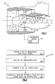
- FIG. 1 schematically illustrates a device, which in this example is a gas turbine engine 10.
- the gas turbine engine 10 includes (in serial flow communication) an inlet section 12, a fan section 14, a low-pressure compressor 18, a high-pressure compressor 22, a combustor 26, a high-pressure turbine 30, and a low-pressure turbine 34 and a exhaust nozzle section 36.
- the gas turbine engine 10 is circumferentially disposed about an engine centerline X.
- air A is pulled into the gas turbine engine 10 by the fan section 14, pressurized by the compressors 18 and 22, mixed with fuel, and burned in the combustor 26.
- the turbines 30 and 34 extract energy from the hot combustion gases flowing from the combustor 26.
- the residual energy is then expanded through the nozzle section to produce thrust.
- the high-pressure turbine 30 utilizes the extracted energy from the hot combustion gases to power the high-pressure compressor 22 through a high speed shaft 38
- the low-pressure turbine 34 utilizes the extracted energy from the hot combustion gases to power the low-pressure compressor 18 and the fan section 14 through a low speed shaft 42.
- the examples described in this disclosure are not limited to the two-spool engine architecture described and may be used in other architectures, such as a single-spool axial design, a three-spool axial design and a three spool axial and centrifugal design, and still other architectures.
- gas turbine engine 10 described and may be used in other types of devices from which data is collected and used to initialize or calibrate, such as internal combustion engines, auxiliary power units, steam turbine engines, pumps, generators, actuators, etc.
- Sensors 46 are configured to collect initialization data from the gas turbine engine 10. Rotor speeds, temperatures, pressures, fuel flow, thrust, etc., are example types of initialization data collected by the sensors 46.
- the initialization data is used to establish the baseline operating conditions for the gas turbine engine 10. Once the baseline operating conditions for the gas turbine engine 10 are established, data collected by the sensors can be compared to the baseline operating conditions.
- the initialization data comprises data collected by the sensors 46 during the first thirty days that the gas turbine engine 10 is in operation. Data collected after the first thirty days the gas turbine engine 10 is in operation is used for comparisons to the baseline operating conditions.
- data collected by the sensors 46 is communicated to a diagnostic system 50 that is mounted separate from the engine 10.
- the diagnostic system 50 is mounted to the engine 10.
- the example diagnostic system 50 includes a control module 54.
- the control module 54 is a computing device and can include a processor, a memory portion, and one or more input and/or output (I/O) device interface(s) that are communicatively coupled via a local interface.
- the local interface can include, for example but not limited to, one or more buses and/or other wired or wireless connections.
- the local interface may have additional elements, which are omitted for simplicity, such as controllers, buffers (caches), drivers, repeaters, and receivers to enable communications. Further, the local interface may include address, control, and/or data connections to enable appropriate communications among the aforementioned components.
- the processor or controller may be a hardware device for executing software, particularly software stored in the memory portion.
- the processor can be a custom made or commercially available processor, a central processing unit (CPU), an auxiliary processor among several processors associated with the computing device, a semiconductor based microprocessor (in the form of a microchip or chip set) or generally any device for executing software instructions.
- the memory portion can include any one or combination of volatile memory elements (e.g., random access memory (RAM, such as DRAM, SRAM, SDRAM, VRAM, etc.)) and/or nonvolatile memory elements (e.g., ROM, hard drive, tape, CD-ROM, etc.).
- volatile memory elements e.g., random access memory (RAM, such as DRAM, SRAM, SDRAM, VRAM, etc.)
- nonvolatile memory elements e.g., ROM, hard drive, tape, CD-ROM, etc.
- the memory may incorporate electronic, magnetic, optical, and/or other types of storage media. Note that the memory can also have a distributed architecture, where various components are situated remotely from one another, but can be accessed by the processor.
- the software in the memory portion may include one or more additional separate programs, each of which includes an ordered listing of executable instructions for implementing logical functions.
- a system component embodied as software may also be construed as a source program, executable program (object code), script, or any other entity comprising a set of instructions to be performed.
- the program is translated via a compiler, assembler, interpreter, or the like, which may or may not be included within the memory.
- the Input/Output devices that may be coupled to system I/O Interface(s) may include input devices, for example but not limited to, a keyboard, mouse, scanner, microphone, camera, proximity device, etc. Further, the Input/Output devices may also include output devices, for example but not limited to, a printer, display, etc. Finally, the Input/Output devices may further include devices that communicate both as inputs and outputs, for instance but not limited to, a modulator/demodulator (modem; for accessing another device, system, or network), a radio frequency (RF) or other transceiver, a telephonic interface, a bridge, a router, etc.
- modem for accessing another device, system, or network
- RF radio frequency
- the processor can be configured to execute software stored within the memory portion, to communicate data to and from the memory portion, and to generally control operations of the computing device pursuant to the software.
- Software in memory in whole or in part, is read by the processor, perhaps buffered within the processor, and then executed.
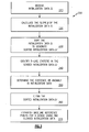
- an example data assessment method 100 used within the diagnostic system 50 includes a step 110 of receiving a set of initialization data from a device, which, in this example, is the gas turbine engine 10.
- the set of initialization data received in the step 110 represents data collected by the sensors 46 during the first thirty days of operating the gas turbine engine 10.
- the method 100 analyses the initialization data from the step 110.
- the analysis includes detecting anomalous data within the set of initialization data. Examples of the detected anomalous data, or the detected anomalies within the set of initialization data, include outlying data points, bimodality in the set of initialization data, and trends in the set of initialization data.
- the method 100 next establishes a set of cleaned data at step 130. If no anomalies are detected at step 120, the set of cleaned data established at step 130 is the same as the set of initialization data received at step 110. If anomalies are detected at step 120, the anomalies are removed to establish the set of cleaned data at the step 130. Examples of establishing the cleaned data at the step 130 include removing outlying data points from the set of initialization data. Another example of establishing the cleaned data at the step 120 includes removing data points associated with a mode within the initialization data to eliminate bimodality.
- the method 100 establishes a reference point for the device using the cleaned data.
- the reference point includes a baseline flow capacity for the gas turbine engine 10, for example.
- Another example reference point includes a baseline flow efficiency for the engine 10.
- establishing the set of cleaned data at step 130 ensures that outlying data points and other anomalies within the set of initialization data do not significantly influence the establishment of the reference point at the step 140.
- another example method 200 receives initialization data ⁇ at a step 210.
- the initialization data set ⁇ ( ⁇ Z1, Z2, ..., ZN ⁇ ) contains N data points, and each data point is a measurement variable.
- Example measurement variables used in the diagnosis system 50 of the gas turbine engine 10 represent the percent deviation from the expected value of speed, fuel flow, exhaust gas temperature, etc.
- the method 200 next calculates the slope ⁇ of the initialization data ⁇ at a step 220.
- the example method 200 utilizes the slope ⁇ to determine if the initialization data ⁇ has a trend.
- the method 200 next sorts the initialization data ⁇ at a step 230 to provide a set of sorted initialization data ⁇ '.
- the example method 200 utilizes the sorted initialization data ⁇ ' to determine if the initialization data ⁇ is bimodal.
- the method 200 next measures data separation between groups of the sorted initialization data ⁇ ' at a step 240 to determine if there is bimodality within the initialization data ⁇ '.
- the step 240 divides the sorted initialization data ⁇ ' into two groups or clusters ( ⁇ 1' and ⁇ 2') that contain N1 and N2 data points respectively.
- the step 240 determines a T-like statistic t for the groups ⁇ 1' and ⁇ 2'.
- the T-like statistic t is a measurement of the distance between an average value of the first group ⁇ 1' having N1 data points and an average value of the second group ⁇ 1' having N2 data points.
- N1 + N2 equals the total number of data points in the set of sorted initialization data ⁇ '.
- the step 240 varies the number of data points in the groups N1 and N2, which changes the T-like statistic t.
- the step 240 notes the groups ⁇ 1' and ⁇ 2' having the maximum T-like statistic t.
- the method 200 uses the slope ⁇ of the initialization data ⁇ and the groups ⁇ 1' and ⁇ 2' having the maximum T-like statistic t at a step 250 to determine if bimodality, a trend,
- the sorted initialization data ⁇ ' from the step 250 is cleaned of the anomaly at a step 260.
- the actual thresholds for decisions are derived from experimental data, for example.
- the method removes outliers from the initialization data ⁇ automatically unless the number of outliers exceeds a predetermined threshold (20% of the given data set size, for example).
- the step 250 generates an alert signal if bimodality, a trend, or an outlying data point is detected within the initialization data ⁇ .
- An example automatic action is removing a minor mode if a bimodality is detected and the minor mode population is so small (less than 20% of total population for example).
- a larger slope ⁇ indicates a trend in the initialization data ⁇ , which can indicate that a gradual fault is developing in the engine 10.
- a larger T-statistic t indicates significant separation between portions of the initialization data ⁇ , which can indicate sudden change or substantial intermittent fault in the engine 10.
- the example method 200 further cleans the initialization data ⁇ in some examples.
- the method 200 may apply the Grubb test to identify outlying data points that were not removed in the step 260.
- ⁇ " ⁇ Z1, Z2, ..., ZN ⁇ is the data set that has been cleaned in the step 260.
- the Grubb test calculates the mean Z for the data points in ⁇ " and then calculates std S for the data points in ⁇ ".
- Gcritical is calculated as a function of N and confidence level ⁇ (95% for example): If G > Gcritical then is considered an outlier and is removed from ⁇ ". The Grubb test is repeated until no further outliers are identified.
- the method 200 establishes a baseline operating condition for the engine 10 using the set of cleaned set of data from step 260.
- features of the disclosed examples include establishing a more robust baseline for a device as the baseline is based on a cleaner data set and more accurately represents normal engine operating conditions.
- the more robust baseline facilitates detecting faults using a fault detector.
- Another feature of the disclosed examples include generating an alert if a bimodal or trend is detected which allows a prompt detection for the fault if the fault resides in the initialization data set.
Landscapes
- Physics & Mathematics (AREA)
- General Physics & Mathematics (AREA)
- Engineering & Computer Science (AREA)
- Automation & Control Theory (AREA)
- Testing And Monitoring For Control Systems (AREA)
- Testing, Inspecting, Measuring Of Stereoscopic Televisions And Televisions (AREA)
- Monitoring And Testing Of Transmission In General (AREA)
Abstract
Description
- This invention relates generally to detecting anomalous data. More particularly, this invention relates to removing anomalous data within initialization data collected from a device, and using the remaining data to establish baseline operating conditions for the device.
- Assessing the health of a device often includes a comparison of data collected from the device to a baseline operating condition of the device. Substantial differences between the collected data and the baseline operating condition of the device may identify performance issues, needed repairs, needed inspections, etc. For example, substantial differences between a temperature measurement collected from a component of the device and the component's baseline temperature measurement may prompt a technician to inspect that component.
- The baseline operating conditions generally represent normal operating conditions of the device. The baseline operating conditions are typically established during an initialization process for the device. As can be appreciated, incorrectly established baseline operating conditions can disadvantageously result in unreliable comparisons between the collected data and the baseline operating condition.
- In one example, the device is a gas turbine engine. Rotor speeds, temperatures, pressures, fuel flows, etc. are all measured during the engine's initialization process, which corresponds to the engine's first thirty days of use, for example. The data collected during this time is assembled into a set of initialization data, and used to establish the engine's baseline operating conditions. Anomalies in the data, such as bimodal, trend, or outliers, can influence the established baseline measurement.
- An example data assessment method for a diagnostic system includes receiving a set of initialization data, analyzing the set of initialization data to identify a data outlier in the set of initialization data, and determining whether the set of initialization data is bimodal. The method further includes establishing a set of cleaned data based on the analysis and establishing a baseline operating condition for the device using the set of cleaned data.
- A further example data assessment method for an engine diagnostic system includes receiving initialization data collected from an engine, detecting outlying data points within the initialization data, and determining if there are multiple modes within the data. The data assessment method further includes cleaning the data to establish a group of cleaned data and establishing a baseline operating condition of the engine using the group of cleaned data.
- An example diagnostic system includes a control module configured to receive initialization data from a device. The control module is configured to determine outliers within the received initialization data and modalities within the received initialization data. The control module is further configured to establish a reference point for the device.
- These and other features of the example disclosure can be best understood from the following specification and drawings, the following of which is a brief description:
-
-
Figure 1 shows a partial schematic view of a gas turbine engine monitored by an example computing module. -
Figure 2 shows the flow of an example data assessment method for theFigure 1 computer module. -
Figure 3 shows a more detailed flow of an example method for theFigure 1 computer module. -
Figure 1 schematically illustrates a device, which in this example is agas turbine engine 10. Thegas turbine engine 10 includes (in serial flow communication) an inlet section 12, afan section 14, a low-pressure compressor 18, a high-pressure compressor 22, acombustor 26, a high-pressure turbine 30, and a low-pressure turbine 34 and a exhaust nozzle section 36. Thegas turbine engine 10 is circumferentially disposed about an engine centerline X. During operation, air A is pulled into thegas turbine engine 10 by thefan section 14, pressurized by thecompressors combustor 26. Theturbines combustor 26. The residual energy is then expanded through the nozzle section to produce thrust. - In a two-spool design, the high-
pressure turbine 30 utilizes the extracted energy from the hot combustion gases to power the high-pressure compressor 22 through ahigh speed shaft 38, and the low-pressure turbine 34 utilizes the extracted energy from the hot combustion gases to power the low-pressure compressor 18 and thefan section 14 through alow speed shaft 42. - The examples described in this disclosure are not limited to the two-spool engine architecture described and may be used in other architectures, such as a single-spool axial design, a three-spool axial design and a three spool axial and centrifugal design, and still other architectures.
- The examples described herein are also not limited to the
gas turbine engine 10 described and may be used in other types of devices from which data is collected and used to initialize or calibrate, such as internal combustion engines, auxiliary power units, steam turbine engines, pumps, generators, actuators, etc. -
Sensors 46 are configured to collect initialization data from thegas turbine engine 10. Rotor speeds, temperatures, pressures, fuel flow, thrust, etc., are example types of initialization data collected by thesensors 46. The initialization data is used to establish the baseline operating conditions for thegas turbine engine 10. Once the baseline operating conditions for thegas turbine engine 10 are established, data collected by the sensors can be compared to the baseline operating conditions. - In one example, the initialization data comprises data collected by the
sensors 46 during the first thirty days that thegas turbine engine 10 is in operation. Data collected after the first thirty days thegas turbine engine 10 is in operation is used for comparisons to the baseline operating conditions. - In this example, data collected by the
sensors 46 is communicated to adiagnostic system 50 that is mounted separate from theengine 10. In another example, thediagnostic system 50 is mounted to theengine 10. - The example
diagnostic system 50 includes acontrol module 54. There are various types of thecontrol module 54 that can be used to implement the functionality described in this disclosure. In terms of hardware architecture, theexample control module 54 is a computing device and can include a processor, a memory portion, and one or more input and/or output (I/O) device interface(s) that are communicatively coupled via a local interface. The local interface can include, for example but not limited to, one or more buses and/or other wired or wireless connections. The local interface may have additional elements, which are omitted for simplicity, such as controllers, buffers (caches), drivers, repeaters, and receivers to enable communications. Further, the local interface may include address, control, and/or data connections to enable appropriate communications among the aforementioned components. - The processor or controller may be a hardware device for executing software, particularly software stored in the memory portion. The processor can be a custom made or commercially available processor, a central processing unit (CPU), an auxiliary processor among several processors associated with the computing device, a semiconductor based microprocessor (in the form of a microchip or chip set) or generally any device for executing software instructions.
- The memory portion can include any one or combination of volatile memory elements (e.g., random access memory (RAM, such as DRAM, SRAM, SDRAM, VRAM, etc.)) and/or nonvolatile memory elements (e.g., ROM, hard drive, tape, CD-ROM, etc.). Moreover, the memory may incorporate electronic, magnetic, optical, and/or other types of storage media. Note that the memory can also have a distributed architecture, where various components are situated remotely from one another, but can be accessed by the processor.
- The software in the memory portion may include one or more additional separate programs, each of which includes an ordered listing of executable instructions for implementing logical functions. A system component embodied as software may also be construed as a source program, executable program (object code), script, or any other entity comprising a set of instructions to be performed. When constructed as a source program, the program is translated via a compiler, assembler, interpreter, or the like, which may or may not be included within the memory.
- The Input/Output devices that may be coupled to system I/O Interface(s) may include input devices, for example but not limited to, a keyboard, mouse, scanner, microphone, camera, proximity device, etc. Further, the Input/Output devices may also include output devices, for example but not limited to, a printer, display, etc. Finally, the Input/Output devices may further include devices that communicate both as inputs and outputs, for instance but not limited to, a modulator/demodulator (modem; for accessing another device, system, or network), a radio frequency (RF) or other transceiver, a telephonic interface, a bridge, a router, etc.
- When the
control module 54 is in operation, the processor can be configured to execute software stored within the memory portion, to communicate data to and from the memory portion, and to generally control operations of the computing device pursuant to the software. Software in memory, in whole or in part, is read by the processor, perhaps buffered within the processor, and then executed. - Referring to
Figure 2 with continuing reference toFigure 1 , an exampledata assessment method 100 used within thediagnostic system 50 includes astep 110 of receiving a set of initialization data from a device, which, in this example, is thegas turbine engine 10. In this example, the set of initialization data received in thestep 110 represents data collected by thesensors 46 during the first thirty days of operating thegas turbine engine 10. - At a
step 120, themethod 100 analyses the initialization data from thestep 110. The analysis includes detecting anomalous data within the set of initialization data. Examples of the detected anomalous data, or the detected anomalies within the set of initialization data, include outlying data points, bimodality in the set of initialization data, and trends in the set of initialization data. - The
method 100 next establishes a set of cleaned data atstep 130. If no anomalies are detected atstep 120, the set of cleaned data established atstep 130 is the same as the set of initialization data received atstep 110. If anomalies are detected atstep 120, the anomalies are removed to establish the set of cleaned data at thestep 130. Examples of establishing the cleaned data at thestep 130 include removing outlying data points from the set of initialization data. Another example of establishing the cleaned data at thestep 120 includes removing data points associated with a mode within the initialization data to eliminate bimodality. - At a step 140, the
method 100 establishes a reference point for the device using the cleaned data. The reference point includes a baseline flow capacity for thegas turbine engine 10, for example. Another example reference point includes a baseline flow efficiency for theengine 10. - As can be appreciated, establishing the set of cleaned data at
step 130 ensures that outlying data points and other anomalies within the set of initialization data do not significantly influence the establishment of the reference point at the step 140. - Referring to
Figure 3 with continuing reference toFigure 1 and 2 , anotherexample method 200 receives initialization data Ω at astep 210. In one example, the initialization data set Ω ({Z1, Z2, ..., ZN}) contains N data points, and each data point is a measurement variable. Example measurement variables used in thediagnosis system 50 of thegas turbine engine 10 represent the percent deviation from the expected value of speed, fuel flow, exhaust gas temperature, etc. - The
method 200 next calculates the slope β of the initialization data Ω at astep 220. Theexample method 200 utilizes the slope β to determine if the initialization data Ω has a trend. - In this example, the slope β of the initialization data Ω is calculated as follows:


Themethod 200 next sorts the initialization data Ω at astep 230 to provide a set of sorted initialization data Ω'. Theexample method 200 utilizes the sorted initialization data Ω' to determine if the initialization data Ω is bimodal. - In this example, the sorted initialization data Ω' is determined as follows: Ω' = {Z(1), Z(2), ..., Z(N)}, where Z(1) ≤ Z(2) ≤, ...,≤ Z(N).
Themethod 200 next measures data separation between groups of the sorted initialization data Ω' at astep 240 to determine if there is bimodality within the initialization data Ω'. In this example, thestep 240 divides the sorted initialization data Ω' into two groups or clusters (Ω1' and Ω2') that contain N1 and N2 data points respectively. Thestep 240 then determines a T-like statistic t for the groups Ω1' and Ω2'. The T-like statistic t is a measurement of the distance between an average value of the first group Ω1' having N1 data points and an average value of the second group Ω1' having N2 data points. N1 + N2 equals the total number of data points in the set of sorted initialization data Ω'. Thestep 240 varies the number of data points in the groups N1 and N2, which changes the T-like statistic t. Thestep 240 notes the groups Ω1' and Ω2' having the maximum T-like statistic t. - In this example, the T-like statistic t is determined as follows:


Themethod 200 then uses the slope β of the initialization data Ω and the groups Ω1' and Ω2' having the maximum T-like statistic t at astep 250 to determine if bimodality, a trend, an outlying data point, or another anomaly exists in the initialization data Ω. - The sorted initialization data Ω' from the
step 250 is cleaned of the anomaly at astep 260. The actual thresholds for decisions are derived from experimental data, for example. - In one example, the method removes outliers from the initialization data Ω automatically unless the number of outliers exceeds a predetermined threshold (20% of the given data set size, for example). In one example, the
step 250 generates an alert signal if bimodality, a trend, or an outlying data point is detected within the initialization data Ω. An example automatic action is removing a minor mode if a bimodality is detected and the minor mode population is so small (less than 20% of total population for example). - In one example, a larger slope β indicates a trend in the initialization data Ω, which can indicate that a gradual fault is developing in the
engine 10. - In one example, a larger T-statistic t indicates significant separation between portions of the initialization data Ω, which can indicate sudden change or substantial intermittent fault in the
engine 10. - The
example method 200 further cleans the initialization data Ω in some examples. Themethod 200, for example, may apply the Grubb test to identify outlying data points that were not removed in thestep 260. In this example, Ω" = {Z1, Z2, ..., ZN} is the data set that has been cleaned in thestep 260. The Grubb test calculates the mean Z for the data points in Ω" and then calculates std S for the data points in Ω". The maximum Grubb distance G among all data points in Ω" is then calculated as indicated below: represents the value of Z that maximized the Grubb distance in the above equation.
- Next, from the Grubb Outlier Critical Value Table, Gcritical is calculated as a function of N and confidence level α (95% for example): If G > Gcritical thenis considered an outlier and is removed from Ω". The Grubb test is repeated until no further outliers are identified.

- The
method 200, at astep 270, establishes a baseline operating condition for theengine 10 using the set of cleaned set of data fromstep 260. - Although described as analyzing data to establish a baseline for operation of the device, those skilled in the art and having the benefit of this disclosure would understand that the methods described herein are also applicable to detecting other data anomalies, such as detecting a bimodal-like event or trend during routine engine monitoring.
- Features of the disclosed examples include establishing a more robust baseline for a device as the baseline is based on a cleaner data set and more accurately represents normal engine operating conditions. The more robust baseline facilitates detecting faults using a fault detector. Another feature of the disclosed examples include generating an alert if a bimodal or trend is detected which allows a prompt detection for the fault if the fault resides in the initialization data set.
- Although a preferred embodiment has been disclosed, a worker of ordinary skill in this art would recognize that certain modifications would come within the scope of this invention. For that reason, the following claims should be studied to determine the true scope and content of this invention.
Claims (15)
- A data assessment method for a diagnostic system, said method comprising:(a) receiving a set of initialization data (110);(b) identifying a data outlier in the set of initialization data;(c) determining whether the set of initialization data has multiple modes;(d) establishing a set of cleaned data (130) based on said step (b) and said step (c); and(e) establishing at least one baseline operating condition (140) for a device using the set of cleaned data established in said step (d).
- The data assessment method of claim 1, wherein the device is a gas turbine engine (10).
- The data assessment method of claim 1 or 2, including analyzing the set of initialization data to determine a data trend, and using the trend when establishing the set of cleaned data.
- The data assessment method of claim 1, 2 or 3, wherein establishing the set of cleaned data comprises removing the data outlier identified in said step (b).
- The data assessment method of any preceding claim, wherein establishing the set of cleaned data comprises removing data from the set of initialization data to remove the modality identified in said step (c).
- The data assessment method of claim 1 for an engine diagnostic system, wherein:said device is an engine assembly;said receiving a set of initialization data is from said engine assembly, for example a gas turbine engine; andsaid establishing a set of cleaned data is by cleaning the set of initialization data based on said step (b) and said step (c).
- The data assessment method of claim 6, including determining if the set of initialization data has a trend, and establishing the at least one baseline operating condition using the trend.
- The data assessment method of claim 6 or 7, wherein the cleaning comprises removing the data outlier identified in said step (b) and removing data from the set of initialization data associated with one or more of the multiple modes detected in said step (c).
- The data assessment method of claim 6, 7 or 8, wherein the cleaning comprises removing data from the set of data to establish a single mode.
- The data assessment method of any of claims 6 to 9, including generating an alert if outlying initialization data is detected in said step (b), if multiple modes are determined in said step (c), or if a trend in the set of initialization data is detected.
- The data assessment method of any preceding claim, wherein said step (b) comprises using the Grubb test to identify the data outlier in the set of initialization data.
- The data assessment method of any preceding claim, wherein said step (c) comprises determining if the set of initialization data is bimodal.
- A device diagnostic system comprising:a control module that receives a group of initialization data collected from a device, for example a turbine engine, and establishes a reference point for the device using at least a portion of the group of initialization data, wherein the control module is configured to remove initialization data from the group of initialization data to eliminate bimodality in the group of initialization data, wherein the control module if further configured to remove outlying initialization data from the group of initialization data.
- The device diagnostic system of claim 13, wherein the control module is further configured to determine if the initialization data has a trend.
- The device diagnostic system of claim 13 or 14, wherein the control module received initialization data from sensors operative to collect data from the device.
Applications Claiming Priority (1)
| Application Number | Priority Date | Filing Date | Title |
|---|---|---|---|
| US12/620,554 US8712729B2 (en) | 2009-11-17 | 2009-11-17 | Anomalous data detection method |
Publications (3)
| Publication Number | Publication Date |
|---|---|
| EP2325709A2 true EP2325709A2 (en) | 2011-05-25 |
| EP2325709A3 EP2325709A3 (en) | 2014-04-02 |
| EP2325709B1 EP2325709B1 (en) | 2020-01-15 |
Family
ID=43543744
Family Applications (1)
| Application Number | Title | Priority Date | Filing Date |
|---|---|---|---|
| EP10251942.8A Active EP2325709B1 (en) | 2009-11-17 | 2010-11-17 | Anomalous data detection method |
Country Status (2)
| Country | Link |
|---|---|
| US (1) | US8712729B2 (en) |
| EP (1) | EP2325709B1 (en) |
Families Citing this family (11)
| Publication number | Priority date | Publication date | Assignee | Title |
|---|---|---|---|---|
| US10023305B2 (en) * | 2012-05-10 | 2018-07-17 | Sikorsky Aircraft Corporation | System and method of determining rotor loads and motion |
| US20140088766A1 (en) * | 2012-09-21 | 2014-03-27 | United Technologies Corporation | Health management having system level diagnostic feedback and information fusion |
| US10443509B2 (en) * | 2014-10-31 | 2019-10-15 | General Electric Company | System and method for turbomachinery vane prognostics and diagnostics |
| US10025939B2 (en) * | 2016-09-28 | 2018-07-17 | Microsoft Technology Licensing, Llc | Internal dataset-based outlier detection for confidential data in a computer system |
| US10255457B2 (en) * | 2016-09-28 | 2019-04-09 | Microsoft Technology Licensing, Llc | Outlier detection based on distribution fitness |
| US10043019B2 (en) * | 2016-09-28 | 2018-08-07 | Microsoft Technology Licensing, Llc | External dataset-based outlier detection for confidential data in a computer system |
| US10519964B2 (en) | 2016-12-06 | 2019-12-31 | General Electric Company | System and method for turbomachinery rotor and blade prognostics and diagnostics |
| US10125779B2 (en) | 2016-12-06 | 2018-11-13 | General Electric Company | System and method for turbomachinery vane diagnostics |
| US11036883B2 (en) | 2017-01-23 | 2021-06-15 | Raytheon Technologies Corporation | Data filtering for data request workflow system |
| US11514056B2 (en) | 2017-01-23 | 2022-11-29 | Raytheon Technologies Corporation | Data request workflow system |
| US10262154B1 (en) | 2017-06-09 | 2019-04-16 | Microsoft Technology Licensing, Llc | Computerized matrix factorization and completion to infer median/mean confidential values |
Family Cites Families (13)
| Publication number | Priority date | Publication date | Assignee | Title |
|---|---|---|---|---|
| US6336082B1 (en) | 1999-03-05 | 2002-01-01 | General Electric Company | Method for automatic screening of abnormalities |
| US7395170B2 (en) | 2001-05-24 | 2008-07-01 | Test Advantage, Inc. | Methods and apparatus for data analysis |
| US7356430B2 (en) | 2001-05-24 | 2008-04-08 | Test Advantage, Inc. | Methods and apparatus for data analysis |
| US8417477B2 (en) | 2001-05-24 | 2013-04-09 | Test Acuity Solutions, Inc. | Methods and apparatus for local outlier detection |
| US6687596B2 (en) | 2001-08-31 | 2004-02-03 | General Electric Company | Diagnostic method and system for turbine engines |
| US7136518B2 (en) * | 2003-04-18 | 2006-11-14 | Medispectra, Inc. | Methods and apparatus for displaying diagnostic data |
| US6909960B2 (en) | 2002-10-31 | 2005-06-21 | United Technologies Corporation | Method for performing gas turbine performance diagnostics |
| US7136809B2 (en) | 2002-10-31 | 2006-11-14 | United Technologies Corporation | Method for performing an empirical test for the presence of bi-modal data |
| CA2417074C (en) | 2003-01-24 | 2009-07-21 | Pratt & Whitney Canada Corp. | Method and system for trend detection and analysis |
| US7904279B2 (en) | 2004-04-02 | 2011-03-08 | Test Advantage, Inc. | Methods and apparatus for data analysis |
| US7769507B2 (en) | 2004-08-26 | 2010-08-03 | United Technologies Corporation | System for gas turbine health monitoring data fusion |
| WO2007028158A2 (en) * | 2005-09-02 | 2007-03-08 | Lightridge Resources Llc | Energy and chemical species utility management system |
| US7286923B2 (en) | 2005-09-30 | 2007-10-23 | General Electric Company | System and method for estimating turbine engine deterioration rate with noisy data |
-
2009
- 2009-11-17 US US12/620,554 patent/US8712729B2/en active Active
-
2010
- 2010-11-17 EP EP10251942.8A patent/EP2325709B1/en active Active
Non-Patent Citations (1)
| Title |
|---|
| None |
Also Published As
| Publication number | Publication date |
|---|---|
| US20110119032A1 (en) | 2011-05-19 |
| EP2325709A3 (en) | 2014-04-02 |
| US8712729B2 (en) | 2014-04-29 |
| EP2325709B1 (en) | 2020-01-15 |
Similar Documents
| Publication | Publication Date | Title |
|---|---|---|
| US8712729B2 (en) | Anomalous data detection method | |
| EP2458178B1 (en) | Turbine performance diagnositic system and methods | |
| JP4346291B2 (en) | Method and system for turbine engine diagnosis | |
| US6868325B2 (en) | Transient fault detection system and method using Hidden Markov Models | |
| US11187621B2 (en) | Fault diagnosis during testing of turbine unit | |
| US20050171736A1 (en) | Health monitoring and diagnostic/prognostic system for an ORC plant | |
| EP1936461A1 (en) | Gas turbine engine performance data validation | |
| US20100262401A1 (en) | Method for analysis of the operation of a gas turbine | |
| EP1926001A2 (en) | Reducing gas turbine performance tracking estimation non-repeatability | |
| US20100114502A1 (en) | System and method for article monitoring | |
| US10767507B2 (en) | Foreign object debris trending concept and design | |
| EP2388672A1 (en) | Identifying of turbomachine faults | |
| JP2010144727A (en) | System and method for monitoring rotor blade health | |
| US10032322B2 (en) | Validation tool for an aircraft engine monitoring system | |
| EP1734354A2 (en) | Engine status detection with external microphone | |
| Tsalavoutas et al. | Combining advanced data analysis methods for the constitution of an integrated gas turbine condition monitoring and diagnostic system | |
| CN104428727A (en) | Method for detecting deterioration in a turbomachine by monitoring the performance of said turbomachine | |
| US7702447B2 (en) | Method and system for identifying gas turbine engine faults | |
| CN109711000A (en) | A kind of Aero-Engine Start method for diagnosing faults based on firing test data | |
| EP1927915A2 (en) | State initialization for gas turbine engine performance diagnogtics | |
| KR20200137295A (en) | Apparatus for detecting combustor instability and method thereof | |
| JP4523826B2 (en) | Gas turbine monitoring device and gas turbine monitoring system | |
| RU103575U1 (en) | SYSTEM OF PARAMETRIC DIAGNOSTICS OF THE COMPRESSOR OF A GAS TURBINE ENGINE | |
| JP2001090554A (en) | Gas turbine abnormality diagnosis method | |
| Romessis et al. | The use of probabilistic reasoning to improve least squares based gas path diagnostics |
Legal Events
| Date | Code | Title | Description |
|---|---|---|---|
| PUAI | Public reference made under article 153(3) epc to a published international application that has entered the european phase |
Free format text: ORIGINAL CODE: 0009012 |
|
| AK | Designated contracting states |
Kind code of ref document: A2 Designated state(s): AL AT BE BG CH CY CZ DE DK EE ES FI FR GB GR HR HU IE IS IT LI LT LU LV MC MK MT NL NO PL PT RO RS SE SI SK SM TR |
|
| AX | Request for extension of the european patent |
Extension state: BA ME |
|
| PUAL | Search report despatched |
Free format text: ORIGINAL CODE: 0009013 |
|
| AK | Designated contracting states |
Kind code of ref document: A3 Designated state(s): AL AT BE BG CH CY CZ DE DK EE ES FI FR GB GR HR HU IE IS IT LI LT LU LV MC MK MT NL NO PL PT RO RS SE SI SK SM TR |
|
| AX | Request for extension of the european patent |
Extension state: BA ME |
|
| RIC1 | Information provided on ipc code assigned before grant |
Ipc: G05B 19/048 20060101AFI20140221BHEP Ipc: G05B 23/02 20060101ALI20140221BHEP |
|
| 17P | Request for examination filed |
Effective date: 20141002 |
|
| RBV | Designated contracting states (corrected) |
Designated state(s): AL AT BE BG CH CY CZ DE DK EE ES FI FR GB GR HR HU IE IS IT LI LT LU LV MC MK MT NL NO PL PT RO RS SE SI SK SM TR |
|
| RAP1 | Party data changed (applicant data changed or rights of an application transferred) |
Owner name: UNITED TECHNOLOGIES CORPORATION |
|
| STAA | Information on the status of an ep patent application or granted ep patent |
Free format text: STATUS: EXAMINATION IS IN PROGRESS |
|
| 17Q | First examination report despatched |
Effective date: 20171220 |
|
| GRAP | Despatch of communication of intention to grant a patent |
Free format text: ORIGINAL CODE: EPIDOSNIGR1 |
|
| STAA | Information on the status of an ep patent application or granted ep patent |
Free format text: STATUS: GRANT OF PATENT IS INTENDED |
|
| INTG | Intention to grant announced |
Effective date: 20190807 |
|
| GRAS | Grant fee paid |
Free format text: ORIGINAL CODE: EPIDOSNIGR3 |
|
| GRAA | (expected) grant |
Free format text: ORIGINAL CODE: 0009210 |
|
| STAA | Information on the status of an ep patent application or granted ep patent |
Free format text: STATUS: THE PATENT HAS BEEN GRANTED |
|
| AK | Designated contracting states |
Kind code of ref document: B1 Designated state(s): AL AT BE BG CH CY CZ DE DK EE ES FI FR GB GR HR HU IE IS IT LI LT LU LV MC MK MT NL NO PL PT RO RS SE SI SK SM TR |
|
| REG | Reference to a national code |
Ref country code: CH Ref legal event code: EP Ref country code: GB Ref legal event code: FG4D |
|
| REG | Reference to a national code |
Ref country code: IE Ref legal event code: FG4D |
|
| REG | Reference to a national code |
Ref country code: DE Ref legal event code: R096 Ref document number: 602010062785 Country of ref document: DE |
|
| REG | Reference to a national code |
Ref country code: AT Ref legal event code: REF Ref document number: 1225700 Country of ref document: AT Kind code of ref document: T Effective date: 20200215 |
|
| REG | Reference to a national code |
Ref country code: NL Ref legal event code: MP Effective date: 20200115 |
|
| REG | Reference to a national code |
Ref country code: LT Ref legal event code: MG4D |
|
| PG25 | Lapsed in a contracting state [announced via postgrant information from national office to epo] |
Ref country code: NO Free format text: LAPSE BECAUSE OF FAILURE TO SUBMIT A TRANSLATION OF THE DESCRIPTION OR TO PAY THE FEE WITHIN THE PRESCRIBED TIME-LIMIT Effective date: 20200415 Ref country code: PT Free format text: LAPSE BECAUSE OF FAILURE TO SUBMIT A TRANSLATION OF THE DESCRIPTION OR TO PAY THE FEE WITHIN THE PRESCRIBED TIME-LIMIT Effective date: 20200607 Ref country code: FI Free format text: LAPSE BECAUSE OF FAILURE TO SUBMIT A TRANSLATION OF THE DESCRIPTION OR TO PAY THE FEE WITHIN THE PRESCRIBED TIME-LIMIT Effective date: 20200115 Ref country code: RS Free format text: LAPSE BECAUSE OF FAILURE TO SUBMIT A TRANSLATION OF THE DESCRIPTION OR TO PAY THE FEE WITHIN THE PRESCRIBED TIME-LIMIT Effective date: 20200115 Ref country code: NL Free format text: LAPSE BECAUSE OF FAILURE TO SUBMIT A TRANSLATION OF THE DESCRIPTION OR TO PAY THE FEE WITHIN THE PRESCRIBED TIME-LIMIT Effective date: 20200115 |
|
| PG25 | Lapsed in a contracting state [announced via postgrant information from national office to epo] |
Ref country code: LV Free format text: LAPSE BECAUSE OF FAILURE TO SUBMIT A TRANSLATION OF THE DESCRIPTION OR TO PAY THE FEE WITHIN THE PRESCRIBED TIME-LIMIT Effective date: 20200115 Ref country code: SE Free format text: LAPSE BECAUSE OF FAILURE TO SUBMIT A TRANSLATION OF THE DESCRIPTION OR TO PAY THE FEE WITHIN THE PRESCRIBED TIME-LIMIT Effective date: 20200115 Ref country code: IS Free format text: LAPSE BECAUSE OF FAILURE TO SUBMIT A TRANSLATION OF THE DESCRIPTION OR TO PAY THE FEE WITHIN THE PRESCRIBED TIME-LIMIT Effective date: 20200515 Ref country code: GR Free format text: LAPSE BECAUSE OF FAILURE TO SUBMIT A TRANSLATION OF THE DESCRIPTION OR TO PAY THE FEE WITHIN THE PRESCRIBED TIME-LIMIT Effective date: 20200416 Ref country code: HR Free format text: LAPSE BECAUSE OF FAILURE TO SUBMIT A TRANSLATION OF THE DESCRIPTION OR TO PAY THE FEE WITHIN THE PRESCRIBED TIME-LIMIT Effective date: 20200115 Ref country code: BG Free format text: LAPSE BECAUSE OF FAILURE TO SUBMIT A TRANSLATION OF THE DESCRIPTION OR TO PAY THE FEE WITHIN THE PRESCRIBED TIME-LIMIT Effective date: 20200415 |
|
| REG | Reference to a national code |
Ref country code: DE Ref legal event code: R097 Ref document number: 602010062785 Country of ref document: DE |
|
| PG25 | Lapsed in a contracting state [announced via postgrant information from national office to epo] |
Ref country code: DK Free format text: LAPSE BECAUSE OF FAILURE TO SUBMIT A TRANSLATION OF THE DESCRIPTION OR TO PAY THE FEE WITHIN THE PRESCRIBED TIME-LIMIT Effective date: 20200115 Ref country code: EE Free format text: LAPSE BECAUSE OF FAILURE TO SUBMIT A TRANSLATION OF THE DESCRIPTION OR TO PAY THE FEE WITHIN THE PRESCRIBED TIME-LIMIT Effective date: 20200115 Ref country code: ES Free format text: LAPSE BECAUSE OF FAILURE TO SUBMIT A TRANSLATION OF THE DESCRIPTION OR TO PAY THE FEE WITHIN THE PRESCRIBED TIME-LIMIT Effective date: 20200115 Ref country code: LT Free format text: LAPSE BECAUSE OF FAILURE TO SUBMIT A TRANSLATION OF THE DESCRIPTION OR TO PAY THE FEE WITHIN THE PRESCRIBED TIME-LIMIT Effective date: 20200115 Ref country code: CZ Free format text: LAPSE BECAUSE OF FAILURE TO SUBMIT A TRANSLATION OF THE DESCRIPTION OR TO PAY THE FEE WITHIN THE PRESCRIBED TIME-LIMIT Effective date: 20200115 Ref country code: RO Free format text: LAPSE BECAUSE OF FAILURE TO SUBMIT A TRANSLATION OF THE DESCRIPTION OR TO PAY THE FEE WITHIN THE PRESCRIBED TIME-LIMIT Effective date: 20200115 Ref country code: SK Free format text: LAPSE BECAUSE OF FAILURE TO SUBMIT A TRANSLATION OF THE DESCRIPTION OR TO PAY THE FEE WITHIN THE PRESCRIBED TIME-LIMIT Effective date: 20200115 Ref country code: SM Free format text: LAPSE BECAUSE OF FAILURE TO SUBMIT A TRANSLATION OF THE DESCRIPTION OR TO PAY THE FEE WITHIN THE PRESCRIBED TIME-LIMIT Effective date: 20200115 |
|
| REG | Reference to a national code |
Ref country code: AT Ref legal event code: MK05 Ref document number: 1225700 Country of ref document: AT Kind code of ref document: T Effective date: 20200115 |
|
| PLBE | No opposition filed within time limit |
Free format text: ORIGINAL CODE: 0009261 |
|
| STAA | Information on the status of an ep patent application or granted ep patent |
Free format text: STATUS: NO OPPOSITION FILED WITHIN TIME LIMIT |
|
| 26N | No opposition filed |
Effective date: 20201016 |
|
| PG25 | Lapsed in a contracting state [announced via postgrant information from national office to epo] |
Ref country code: AT Free format text: LAPSE BECAUSE OF FAILURE TO SUBMIT A TRANSLATION OF THE DESCRIPTION OR TO PAY THE FEE WITHIN THE PRESCRIBED TIME-LIMIT Effective date: 20200115 Ref country code: IT Free format text: LAPSE BECAUSE OF FAILURE TO SUBMIT A TRANSLATION OF THE DESCRIPTION OR TO PAY THE FEE WITHIN THE PRESCRIBED TIME-LIMIT Effective date: 20200115 |
|
| PG25 | Lapsed in a contracting state [announced via postgrant information from national office to epo] |
Ref country code: SI Free format text: LAPSE BECAUSE OF FAILURE TO SUBMIT A TRANSLATION OF THE DESCRIPTION OR TO PAY THE FEE WITHIN THE PRESCRIBED TIME-LIMIT Effective date: 20200115 Ref country code: PL Free format text: LAPSE BECAUSE OF FAILURE TO SUBMIT A TRANSLATION OF THE DESCRIPTION OR TO PAY THE FEE WITHIN THE PRESCRIBED TIME-LIMIT Effective date: 20200115 |
|
| PG25 | Lapsed in a contracting state [announced via postgrant information from national office to epo] |
Ref country code: MC Free format text: LAPSE BECAUSE OF FAILURE TO SUBMIT A TRANSLATION OF THE DESCRIPTION OR TO PAY THE FEE WITHIN THE PRESCRIBED TIME-LIMIT Effective date: 20200115 |
|
| REG | Reference to a national code |
Ref country code: CH Ref legal event code: PL |
|
| PG25 | Lapsed in a contracting state [announced via postgrant information from national office to epo] |
Ref country code: LU Free format text: LAPSE BECAUSE OF NON-PAYMENT OF DUE FEES Effective date: 20201117 |
|
| REG | Reference to a national code |
Ref country code: BE Ref legal event code: MM Effective date: 20201130 |
|
| PG25 | Lapsed in a contracting state [announced via postgrant information from national office to epo] |
Ref country code: LI Free format text: LAPSE BECAUSE OF NON-PAYMENT OF DUE FEES Effective date: 20201130 Ref country code: CH Free format text: LAPSE BECAUSE OF NON-PAYMENT OF DUE FEES Effective date: 20201130 |
|
| PG25 | Lapsed in a contracting state [announced via postgrant information from national office to epo] |
Ref country code: IE Free format text: LAPSE BECAUSE OF NON-PAYMENT OF DUE FEES Effective date: 20201117 |
|
| PG25 | Lapsed in a contracting state [announced via postgrant information from national office to epo] |
Ref country code: TR Free format text: LAPSE BECAUSE OF FAILURE TO SUBMIT A TRANSLATION OF THE DESCRIPTION OR TO PAY THE FEE WITHIN THE PRESCRIBED TIME-LIMIT Effective date: 20200115 Ref country code: MT Free format text: LAPSE BECAUSE OF FAILURE TO SUBMIT A TRANSLATION OF THE DESCRIPTION OR TO PAY THE FEE WITHIN THE PRESCRIBED TIME-LIMIT Effective date: 20200115 Ref country code: CY Free format text: LAPSE BECAUSE OF FAILURE TO SUBMIT A TRANSLATION OF THE DESCRIPTION OR TO PAY THE FEE WITHIN THE PRESCRIBED TIME-LIMIT Effective date: 20200115 |
|
| PG25 | Lapsed in a contracting state [announced via postgrant information from national office to epo] |
Ref country code: MK Free format text: LAPSE BECAUSE OF FAILURE TO SUBMIT A TRANSLATION OF THE DESCRIPTION OR TO PAY THE FEE WITHIN THE PRESCRIBED TIME-LIMIT Effective date: 20200115 Ref country code: AL Free format text: LAPSE BECAUSE OF FAILURE TO SUBMIT A TRANSLATION OF THE DESCRIPTION OR TO PAY THE FEE WITHIN THE PRESCRIBED TIME-LIMIT Effective date: 20200115 |
|
| PG25 | Lapsed in a contracting state [announced via postgrant information from national office to epo] |
Ref country code: BE Free format text: LAPSE BECAUSE OF NON-PAYMENT OF DUE FEES Effective date: 20201130 |
|
| REG | Reference to a national code |
Ref country code: DE Ref legal event code: R081 Ref document number: 602010062785 Country of ref document: DE Owner name: RAYTHEON TECHNOLOGIES CORPORATION (N.D.GES.D.S, US Free format text: FORMER OWNER: UNITED TECHNOLOGIES CORPORATION, FARMINGTON, CONN., US Ref country code: DE Ref legal event code: R081 Ref document number: 602010062785 Country of ref document: DE Owner name: RTX CORPORATION (N.D.GES.D. STAATES DELAWARE),, US Free format text: FORMER OWNER: UNITED TECHNOLOGIES CORPORATION, FARMINGTON, CONN., US |
|
| P01 | Opt-out of the competence of the unified patent court (upc) registered |
Effective date: 20230519 |
|
| REG | Reference to a national code |
Ref country code: DE Ref legal event code: R081 Ref document number: 602010062785 Country of ref document: DE Owner name: RTX CORPORATION (N.D.GES.D. STAATES DELAWARE),, US Free format text: FORMER OWNER: RAYTHEON TECHNOLOGIES CORPORATION (N.D.GES.D.STAATES DELAWARE), ARLINGTON, VA, US |
|
| PGFP | Annual fee paid to national office [announced via postgrant information from national office to epo] |
Ref country code: DE Payment date: 20251022 Year of fee payment: 16 |
|
| PGFP | Annual fee paid to national office [announced via postgrant information from national office to epo] |
Ref country code: GB Payment date: 20251023 Year of fee payment: 16 |
|
| PGFP | Annual fee paid to national office [announced via postgrant information from national office to epo] |
Ref country code: FR Payment date: 20251022 Year of fee payment: 16 |