EP2325677A2 - Dispositifs optiques à changement d'apparence dynamique (DACOD) imprimés dans un champ magnétique formé incluant des structures Fresnel imprimables - Google Patents
Dispositifs optiques à changement d'apparence dynamique (DACOD) imprimés dans un champ magnétique formé incluant des structures Fresnel imprimables Download PDFInfo
- Publication number
- EP2325677A2 EP2325677A2 EP10011761A EP10011761A EP2325677A2 EP 2325677 A2 EP2325677 A2 EP 2325677A2 EP 10011761 A EP10011761 A EP 10011761A EP 10011761 A EP10011761 A EP 10011761A EP 2325677 A2 EP2325677 A2 EP 2325677A2
- Authority
- EP
- European Patent Office
- Prior art keywords
- flakes
- image
- magnetic
- particles
- substrate
- Prior art date
- Legal status (The legal status is an assumption and is not a legal conclusion. Google has not performed a legal analysis and makes no representation as to the accuracy of the status listed.)
- Granted
Links
Images


Classifications
-
- H—ELECTRICITY
- H02—GENERATION; CONVERSION OR DISTRIBUTION OF ELECTRIC POWER
- H02J—CIRCUIT ARRANGEMENTS OR SYSTEMS FOR SUPPLYING OR DISTRIBUTING ELECTRIC POWER; SYSTEMS FOR STORING ELECTRIC ENERGY
- H02J9/00—Circuit arrangements for emergency or stand-by power supply, e.g. for emergency lighting
- H02J9/04—Circuit arrangements for emergency or stand-by power supply, e.g. for emergency lighting in which the distribution system is disconnected from the normal source and connected to a standby source
- H02J9/06—Circuit arrangements for emergency or stand-by power supply, e.g. for emergency lighting in which the distribution system is disconnected from the normal source and connected to a standby source with automatic change-over, e.g. UPS systems
- H02J9/061—Circuit arrangements for emergency or stand-by power supply, e.g. for emergency lighting in which the distribution system is disconnected from the normal source and connected to a standby source with automatic change-over, e.g. UPS systems for DC powered loads
-
- G—PHYSICS
- G02—OPTICS
- G02B—OPTICAL ELEMENTS, SYSTEMS OR APPARATUS
- G02B5/00—Optical elements other than lenses
- G02B5/12—Reflex reflectors
-
- B—PERFORMING OPERATIONS; TRANSPORTING
- B41—PRINTING; LINING MACHINES; TYPEWRITERS; STAMPS
- B41M—PRINTING, DUPLICATING, MARKING, OR COPYING PROCESSES; COLOUR PRINTING
- B41M3/00—Printing processes to produce particular kinds of printed work, e.g. patterns
- B41M3/14—Security printing
- B41M3/148—Transitory images, i.e. images only visible from certain viewing angles
-
- B—PERFORMING OPERATIONS; TRANSPORTING
- B42—BOOKBINDING; ALBUMS; FILES; SPECIAL PRINTED MATTER
- B42D—BOOKS; BOOK COVERS; LOOSE LEAVES; PRINTED MATTER CHARACTERISED BY IDENTIFICATION OR SECURITY FEATURES; PRINTED MATTER OF SPECIAL FORMAT OR STYLE NOT OTHERWISE PROVIDED FOR; DEVICES FOR USE THEREWITH AND NOT OTHERWISE PROVIDED FOR; MOVABLE-STRIP WRITING OR READING APPARATUS
- B42D25/00—Information-bearing cards or sheet-like structures characterised by identification or security features; Manufacture thereof
- B42D25/30—Identification or security features, e.g. for preventing forgery
- B42D25/36—Identification or security features, e.g. for preventing forgery comprising special materials
- B42D25/369—Magnetised or magnetisable materials
-
- B—PERFORMING OPERATIONS; TRANSPORTING
- B42—BOOKBINDING; ALBUMS; FILES; SPECIAL PRINTED MATTER
- B42D—BOOKS; BOOK COVERS; LOOSE LEAVES; PRINTED MATTER CHARACTERISED BY IDENTIFICATION OR SECURITY FEATURES; PRINTED MATTER OF SPECIAL FORMAT OR STYLE NOT OTHERWISE PROVIDED FOR; DEVICES FOR USE THEREWITH AND NOT OTHERWISE PROVIDED FOR; MOVABLE-STRIP WRITING OR READING APPARATUS
- B42D25/00—Information-bearing cards or sheet-like structures characterised by identification or security features; Manufacture thereof
- B42D25/20—Information-bearing cards or sheet-like structures characterised by identification or security features; Manufacture thereof characterised by a particular use or purpose
- B42D25/29—Securities; Bank notes
-
- B—PERFORMING OPERATIONS; TRANSPORTING
- B44—DECORATIVE ARTS
- B44F—SPECIAL DESIGNS OR PICTURES
- B44F1/00—Designs or pictures characterised by special or unusual light effects
- B44F1/02—Designs or pictures characterised by special or unusual light effects produced by reflected light, e.g. matt surfaces, lustrous surfaces
-
- B—PERFORMING OPERATIONS; TRANSPORTING
- B44—DECORATIVE ARTS
- B44F—SPECIAL DESIGNS OR PICTURES
- B44F1/00—Designs or pictures characterised by special or unusual light effects
- B44F1/08—Designs or pictures characterised by special or unusual light effects characterised by colour effects
-
- G—PHYSICS
- G02—OPTICS
- G02B—OPTICAL ELEMENTS, SYSTEMS OR APPARATUS
- G02B26/00—Optical devices or arrangements for the control of light using movable or deformable optical elements
- G02B26/02—Optical devices or arrangements for the control of light using movable or deformable optical elements for controlling the intensity of light
- G02B26/026—Optical devices or arrangements for the control of light using movable or deformable optical elements for controlling the intensity of light based on the rotation of particles under the influence of an external field, e.g. gyricons, twisting ball displays
-
- G—PHYSICS
- G02—OPTICS
- G02B—OPTICAL ELEMENTS, SYSTEMS OR APPARATUS
- G02B27/00—Optical systems or apparatus not provided for by any of the groups G02B1/00 - G02B26/00, G02B30/00
- G02B27/0025—Optical systems or apparatus not provided for by any of the groups G02B1/00 - G02B26/00, G02B30/00 for optical correction, e.g. distorsion, aberration
-
- G—PHYSICS
- G02—OPTICS
- G02B—OPTICAL ELEMENTS, SYSTEMS OR APPARATUS
- G02B5/00—Optical elements other than lenses
- G02B5/08—Mirrors
- G02B5/09—Multifaceted or polygonal mirrors, e.g. polygonal scanning mirrors; Fresnel mirrors
-
- G—PHYSICS
- G09—EDUCATION; CRYPTOGRAPHY; DISPLAY; ADVERTISING; SEALS
- G09F—DISPLAYING; ADVERTISING; SIGNS; LABELS OR NAME-PLATES; SEALS
- G09F3/00—Labels, tag tickets, or similar identification or indication means; Seals; Postage or like stamps
- G09F3/02—Forms or constructions
- G09F3/03—Forms or constructions of security seals
- G09F3/0376—Forms or constructions of security seals using a special technique to detect tampering, e.g. by ultrasonic or optical means
-
- B—PERFORMING OPERATIONS; TRANSPORTING
- B05—SPRAYING OR ATOMISING IN GENERAL; APPLYING FLUENT MATERIALS TO SURFACES, IN GENERAL
- B05D—PROCESSES FOR APPLYING FLUENT MATERIALS TO SURFACES, IN GENERAL
- B05D3/00—Pretreatment of surfaces to which liquids or other fluent materials are to be applied; After-treatment of applied coatings, e.g. intermediate treating of an applied coating preparatory to subsequent applications of liquids or other fluent materials
- B05D3/20—Pretreatment of surfaces to which liquids or other fluent materials are to be applied; After-treatment of applied coatings, e.g. intermediate treating of an applied coating preparatory to subsequent applications of liquids or other fluent materials by magnetic fields
- B05D3/207—Pretreatment of surfaces to which liquids or other fluent materials are to be applied; After-treatment of applied coatings, e.g. intermediate treating of an applied coating preparatory to subsequent applications of liquids or other fluent materials by magnetic fields post-treatment by magnetic fields
-
- B42D2033/16—
-
- B42D2035/20—
-
- Y—GENERAL TAGGING OF NEW TECHNOLOGICAL DEVELOPMENTS; GENERAL TAGGING OF CROSS-SECTIONAL TECHNOLOGIES SPANNING OVER SEVERAL SECTIONS OF THE IPC; TECHNICAL SUBJECTS COVERED BY FORMER USPC CROSS-REFERENCE ART COLLECTIONS [XRACs] AND DIGESTS
- Y10—TECHNICAL SUBJECTS COVERED BY FORMER USPC
- Y10T—TECHNICAL SUBJECTS COVERED BY FORMER US CLASSIFICATION
- Y10T428/00—Stock material or miscellaneous articles
- Y10T428/24—Structurally defined web or sheet [e.g., overall dimension, etc.]
- Y10T428/24802—Discontinuous or differential coating, impregnation or bond [e.g., artwork, printing, retouched photograph, etc.]
-
- Y—GENERAL TAGGING OF NEW TECHNOLOGICAL DEVELOPMENTS; GENERAL TAGGING OF CROSS-SECTIONAL TECHNOLOGIES SPANNING OVER SEVERAL SECTIONS OF THE IPC; TECHNICAL SUBJECTS COVERED BY FORMER USPC CROSS-REFERENCE ART COLLECTIONS [XRACs] AND DIGESTS
- Y10—TECHNICAL SUBJECTS COVERED BY FORMER USPC
- Y10T—TECHNICAL SUBJECTS COVERED BY FORMER US CLASSIFICATION
- Y10T428/00—Stock material or miscellaneous articles
- Y10T428/25—Web or sheet containing structurally defined element or component and including a second component containing structurally defined particles
Definitions
- This invention relates generally to optically variable pigments, films, devices, and images, and more particularly to aligning or orienting magnetic flakes, such as during a painting or printing process, to obtain an illusive optical effect.
- Optically variable devices are used in a wide variety of applications, both decorative and utilitarian, for example such devices are used as security devices on commercial products. Optically variable devices can be made in numerous ways to achieve a variety of effects. Examples of optically variable devices include the holograms imprinted On credit cards and authentic software documentation, colour-shifting images printed on banknotes, and enhancing the surface appearance of items such as motorcycle helmets and wheel covers.
- Optically variable devices can be made as film or foil that is pressed, stamped, glued, or otherwise attached to an object, and can also be made using optically variable pigments.
- One type of optically variable pigment is commonly called a colour-shifting pigment because the apparent colour of images appropriately printed with such pigments changes as the angle of view and/or illumination is tilted.
- a common example is the "20" printed with colour-shifting pigment in the lower right-hand corner of a U.S. twenty-dollar bill, which serves as an anti-counterfeiting device.
- Some anti-counterfeiting devices are covert, while others are intended to be noticed.
- the colour shift of an image printed with colour-shifting pigment might not be noticed under uniform fluorescent ceiling lights, but more noticeable in direct sunlight or under single-point illumination. This can make it easier for a counterfeiter to pass counterfeit notes without the optically variable feature because the recipient might not be aware of the optically variable feature, or because the counterfeit note might look substantially similar to the authentic note under certain conditions.
- Optically variable devices can also be made with magnetic pigments that are aligned with a magnetic field after applying the pigment (typically in a carrier such as an ink vehicle or a paint vehicle) to a surface.
- a carrier such as an ink vehicle or a paint vehicle
- painting with magnetic pigments has been used mostly for decorative purposes.
- use of magnetic pigments has been described to produce painted cover wheels having a decorative feature that appears as a three-dimensional shape.
- a pattern was formed on the painted product by applying a magnetic field to the product while the paint medium still was in a liquid state.
- the paint medium had dispersed magnetic non-spherical particles that aligned along the magnetic field lines.
- the field had two regions. The first region contained lines of a magnetic force that were oriented parallel to the surface and arranged in a shape of a desired pattern.
- the second region contained lines that were non-parallel to the surface of the painted product and arranged around the pattern.
- permanent magnets or electromagnets with the shape corresponding to the shape of desired pattern were located underneath the painted product to orient in the magnetic field non-spherical magnetic particles dispersed in the paint while the paint was still wet.
- the pattern was visible on the surface of the painted product as the light rays incident on the paint layer were influenced differently by the oriented magnetic particles.
- this object is achieved by a security device as defined in claim 1 or 8, an optically illusive image as defined in claim 21, a label as defined in claim 8, and an optical element as defined in claim 22 or claim 24.
- the present invention provides articles, methods and apparatus related to images having an illusive optical effect.
- a security device comprising an image having a first plurality of magnetically alignable flakes resting upon a substrate in a first pattern so as to define a ring or curve.
- a security device comprising an image having a first plurality of magnetically alignable flakes resting upon a substrate in a first pattern so as to define a ring or curve.
- at least n flakes, n > 1000 are provided, and wherein planes extending from surfaces of the flakes intersect with one another.
- the first plurality of magnetically alignable flakes define a plurality of concentric rings of flakes, and the rings of flakes populate a circular-like region; the flakes defining the rings form an increasing or decreasing angle with respect to the substrate from the outermost ring to the inner most ring.
- the device may include a second plurality of magnetically alignable flakes resting upon the substrate in a corresponding pattern to the first pattern wherein the flakes are tilted at a same second angle with respect to the substrate, wherein the second angle is different than the first angle and wherein planes extending from along surfaces of the second plurality of flakes intersect with each other.
- the plurality of magnetically alignable flakes may be distributed substantially throughout an entire closed region and oriented in a predetermined pattern therein, wherein at least more than 50% of the flakes are oriented such that lines normal to their reflecting surfaces converge along a line or to a point.
- the image comprises at least 10,000 flakes or more.
- an optically illusive image comprising a substrate having a region of flakes coating a surface thereof, wherein the flakes are distributed throughout substantially the entire region and oriented in a predetermined pattern therein, wherein the flakes are oriented such that lines normal to their reflecting surfaces converge along a line or to a point.
- a label or security device comprising an optically illusive image having flakes covering and distributed throughout an entire region and oriented in a predetermined pattern, the flakes having reflecting surfaces, wherein the orientation of the flakes forming the predetermined pattern is such that lines normal to the reflecting surfaces of the flakes converge along a line or at a point, wherein the predetermined pattern has an axis of revolution.
- a printed array comprising a plurality of concentric rings of magnetically aligned platelets disposed upon a substrate in the form of a Fresnel structure, preferably a Fresnel reflector.
- a Fresnel structure preferably a Fresnel reflector.
- the image forms a part of a receiving or reflecting antenna and wherein the flakes are selectively absorbing or reflecting, respectively.
- an optical image as described in any of the embodiments described heretofore has a grating thereon and / or the flakes have a surface area between 100 ⁇ m 2 to 1 mm 2 and wherein the flakes are within a range of thickness between 100 nm and 100 ⁇ m.
- the flakes may be uniform in shape, and are preferably hexagonal in shape allowing for a greater packing density.
- an image is provided that forms a light detector, the image being dynamic such that it displays a number of rings corresponding to a number of separate light sources that illuminate the image.
- the present invention in its various embodiments provides novel and inventive magnetic structures useful for security and packaging and labeling applications.
- particles of an optically variable pigment dispersed in a liquid paint or ink vehicle generally orient themselves parallel to the surface when printed or painted on to a surface.
- Orientation parallel to the surface provides high reflectance of incident light from the coated surface.
- Magnetic flakes can be tilted with respect to the substrate while in the liquid medium by applying a magnetic field.
- the flakes generally align in such way that the longest diagonal of a reflective flake and the groove's orientation of the diffractive flake follows a magnetic field line.
- the magnetic field lines can penetrate the substrate at different angles, tilting magnetic flakes to these angles.
- a tilted flake reflects incident light differently than a flake parallel to the surface of the printed substrate.
- the reflectance and hue can both be different.
- Tilted flakes typically look darker and have a different colour than flakes parallel to the surface at a normal viewing angle.
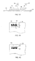
- FIG. 1A is a simplified cross section of a printed image 20 that will be referred to as a "switching" optical effect, or “flip-flop", for purposes of discussion, according to an embodiment of the present invention.
- the flip-flop includes a first printed portion 22 and a second printed portion 24, separated by a transition 25.
- Pigment flakes 26 surrounded by carrier 28, such as an ink vehicle or a paint vehicle have been aligned parallel to a first plane in the first portion, and pigment flakes 26' in the second portion have been aligned parallel to a second plane.
- the flakes are shown as short lines in the cross-sectional view.
- the flakes are magnetic flakes, i.e. pigment flakes that can be aligned using a magnetic field. They might or might not retain remnant magnetization.
- flakes viewed normal to the plane of the flake appear bright, while flakes viewed along the edge of the plane appear dark.
- light from an illumination source 30 is reflected off the flakes in the first region to the viewer 32.
- the flakes in the first region 22 will be viewed on-end, while light will be reflected off the flakes in the second region 24.
- the first region will appear light and the second region will appear dark, while in the second viewing position the fields will flip-flop, the first region becoming dark and the second region becoming light. This provides a very striking visual effect.
- the pigment flakes are colour-shifting, one portion may appear to be a first colour and the other portion another colour.
- the carrier is typically transparent, either clear or tinted, and the flakes are typically fairly reflective.
- the carrier could be tinted green and the flakes could include a metallic layer, such as a thin film of aluminum, gold, nickel, platinum, or metal alloy, or be a metal flake, such as a nickel or alloy flake.
- the light reflected off a metal layer through the green-tinted carrier might appear bright green, while another portion with flakes viewed on end might appear dark green or other colour. If the flakes are merely metallic flakes in a clear carrier, then one portion of the image might appear bright metallic, while another appears dark.
- the metallic flakes might be coated with a tinted layer, or the flakes might include an optical interference structure, such as an absorber-spacer-reflector Fabry-Perot type structure.
- a diffractive structure may be formed on the reflective surface for providing an enhancement and an additional security feature.
- the diffractive structure may have a simple linear grating formed in the reflective surface, or may have a more complex predetermined pattern that can only be discerned when magnified but having an overall effect when viewing. By providing diffractive reflective layer, a colour change or brightness change is seen by a viewer by simply turning the sheet, banknote, or structure having the diffractive flakes.
- FIG. 1B is a simplified plan view of the printed image 20 on the substrate 29, which could be a document, such as a bank note or stock certificate, at a first selected viewing angle.
- the printed image can act as a security and/or authentication feature because the illusive image will not photocopy and cannot be produced using conventional printing techniques.
- the first portion 22 appears bright and the second portion 24 appears dark.
- the section line 40 indicates the cross section shown in FIG. 1A .
- the transition 25 between the first and second portions is relatively sharp.
- the document could be a bank note, stock certificate, or other high-value printed material, for example.
- FIG. 1C is a simplified plan view of the printed image 20 on the substrate 29 at a second selected viewing angle, obtained by tilting the image relative to the point of view.
- the first portion 22 now appears dark, while the second portion 24 appears light.
- the tilt angle at which the image flip-flops depend on the angle between the alignment planes of the flakes in the different portions of the image. In one sample, the image flipped from light to dark when tilted through about 15 degrees.
- FIG. 2A is a simplified cross section of a printed image 42 of a kinematic optical device that will be defined as a micro-arrayed cylindrical Fresnel reflector or as referred to as a "rolling bar" for purposes of discussion, according to another embodiment of the present invention.
- the image includes pigment flakes 26 surrounded by a transparent carrier 28 printed on a substrate 29.
- the pigment flakes are aligned in a curving fashion.
- the region(s) of the rolling bar that reflect light off the faces of the pigment flakes to the viewer appear lighter than areas that do not directly reflect the light to the viewer.
- This image provides a Fresnel focal line that looks very much like a light band(s) or bar(s) that appear to move ("roll") across the image when the image is tilted with respect to the viewing angle (assuming a fixed illumination source(s).
- FIG. 2B is a simplified plan view of the rolling bar image 42 at a first selected viewing angle.
- a bright bar 44 appears in a first position in the image between two contrasting fields 46, 48.
- FIG. 2C is a simplified plan view of the rolling bar image at a second selected viewing angle.
- the bright bar 44' appears to have "moved” to a second position in the image, and the sizes of the contrasting fields 46', 48' have changed.
- the alignment of the pigment flakes creates the illusion of a bar "rolling" down the image as the image is tilted (at a fixed viewing angle and fixed illumination). Tilting the image in the other direction makes the bar appear to roll in the opposite direction (up).
- the bar may also appear to have depth, even though it is printed in a plane.
- the virtual depth can appear to be much greater than the physical thickness of the printed image. It happens because the bar is a imaginary focal line of the cylindrical convex Fresnel reflector located at the focal length underneath the plane of the reflector.
- the tilting of the flakes in a selected pattern reflects light to provide the illusion of depth or "3D", as it is commonly referred to.
- a three-dimensional effect can be obtained by placing a shaped magnet behind the paper or other substrate with magnetic pigment flakes printed on the substrate in a fluid carrier.
- the flakes align along magnetic field lines and create the 3D image after setting (e.g. drying or curing) the carrier.
- the image often appears to move as it is tilted; hence kinematic 3D images may be formed.
- Flip-flops and rolling bars can be printed with magnetic pigment flakes, i.e. pigment flakes that can be aligned using a magnetic field.
- a printed flip-flop type image provides an optically variable device with two distinct fields that can be obtained with a single print step and using a single ink formulation.
- a rolling bar type image provides an optically variable device that has a contrasting band that appears to move as the image is tilted, similar to the semi-precious stone known as Tiger's Eye. These printed images are quite noticeable and the illusive aspects would not photocopy.
- Such images may be applied to bank notes, stock certificates, software documentation, security seals, and similar objects as authentication and/or anti-counterfeiting devices. They are particularly desirable for high-volume printed documents, such as bank notes, packaging, and labels, because they can be printed in a high-speed printing operation, as is described below.
- a "double rolling bar” is an image wherein one portion 44' has magnetic flakes oriented in cylindrical convex fashion while another portion 44" of the image has magnetic flakes oriented in a cylindrical concave orientation.
- the "rolling bar” magnet is placed underneath the paper substrate.
- the magnet is placed above the paper substrate.
- a "Double tilt” image is formed when magnetic flakes in two regions of the image have differing and opposing orientation, for example, +30 degrees and -30 degrees. At one tilted position of the printed image one part of the image is dark and another part is light.
- the areas switch their light and dark regions so that the first image becomes light and the second image becomes dark.
- this switch of the light and dark may occur from the top to the bottom and back, as well as from the left to the right and back, in dependence upon the on orientation of the flakes.
- the bright bar 44' appears to have "moved” to a second position in the image, and the sizes of the contrasting fields 46', 48' have changed; furthermore the bright bar 44" appears to have "moved” to a different position in the image, and the sizes of the contrasting fields 46", 48" have changed.
- Dynamic optical devices are images, some of which may be printed with a high-speed printing press, and which use ink containing magnetic platelet-like pigments in a magnetic field having a predetermined shape.
- the images are able to change their appearance in response to a physical action applied by an observer to the substrate.
- the observer needs to tilt, rotate or bend the substrate to see appearance or disappearance or motion of parts of the image or entire image.
- This behavior of the Dynamic Appearance-Changing Optical Devices (DACOD) depends purely on reflection or dispersion of the incident light from differently oriented magnetic platelets in the layer of dry ink.
- the presence or absence of colour is a complementary feature of the DACODs.
- Magnetic colour-shifting pigments provide a plurality of variations in the colour change of dynamic optical devices in addition to their appearance change.
- This invention describes a special class of dynamic optical devices in part of an image printed through a silk screen, offset, flexo, intaglio, gravure or other known printing methods on a paper or other flat substrate material in magnetic fields of different configurations in such a way that during translation of the printed wet image on the substrate in the field, the platelets of the pigment in the layer of the ink align along magnetic lines of the field causing the images to change their appearance in observations at different angles after drying of the ink.
- the printed image that has an appearance-changing element does not need any special equipment to be viewed and therefore it can be viewed by the naked eye. Tilt of the printed dynamic optical device at different angles with respect to the light source causes attention-grabbing change of appearance or motion in the part of the image that was printed with magnetic ink.
- the ink for the dynamic optical devices consists of an ink vehicle and any light reflecting or light dispersing platelet-based magnetic pigment.
- the pigment can be a colour-shifting pigment, a non colour-shifting pigment, and/or or have a microstructure such as a diffraction grating facilitating orientation of the magnetically aligned flake.
- the ink vehicle may be clear or coloured, UV curable or solvent based.
- Printed appearance-changing optical devices may be used as a security feature on or within bank notes and valuable documents.
- Appearance-changing images printed in magnetic fields, have been described heretofore in the applicants' earlier published United States patent application US 2004/0051297 A1 . Described therein are printed images with a rolling bar effect and a flip-flop effect changing colour or intensity of the reflected light in different parts of the image as the light source or viewing angle changes. Change in the image appearance in these effects doesn't happen instantly as for holograms or lenticular substrates but rather gradually.
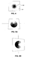
- FIG. 4 is an image that has a dynamic effect in the form of a "star-burst" pattern; and, wherein an image of a cone is shown in FIG. 5A , and an image of a funnel is shown in FIG. 20A .
- the print with the "star burst" image was made using a funnel-shaped magnetic field.
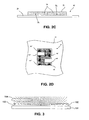
- the cross-section of the platelets' orientation in the layer of printed dry ink is illustrated in FIG. 3 .
- the ink 192 with dispersed magnetic particles 193 is printed on the top of a substrate 191 by one of the printing methods described heretofore.
- Magnetic lines 194 are oriented perpendicularly to the substrate in the center of the image. The magnetic field lines decline with an increase in radial distance from the center; therefore, the field is strongest in the centre and weakens with distance away from the centre, radially outward.
- the center of the printed optical device printed in the funnel-shaped field, shown in FIG. 4 is dark at a normal angle of observation.
- the lightness of the printed image increases gradually from the center out to the edges.
- the dark area appears to move toward the bottom.
- Vertically tilting the image to the right appears to move the shaded part of the image in the direction opposite to the tilt.
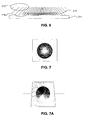
- the cone-shaped magnetic field lines shown in FIG. 6 , align the magnetic platelets in an opposite order to that of the funnel-shaped field. As a result of such orientation, the movement in the image is in the direction opposite to the direction of the images produced in the funnel-shaped image.
- the print made in the cone-shaped field, produces an image with a bright center at a normal angle of observation as shown in FIG. 7 .
- the print is tilted with its upper edge away from the observer the bright region shifts to the bottom as shown in FIG. 7A in contrast to the image in Figure 5A .
- Vertical tilt to the right is illustrated in FIG. 7B which causes a shift of the bright area to the left.
- the cross-section of the particles position aligned in the torus-shaped field is shown in FIG. 8 .
- the ink 806 with dispersed magnetic particles 804 is printed on the substrate 807.
- the described above methods for aligning magnetically alignable flakes or particles can be applied to the images where either entire area is printed wherein the magnetic feature or just a certain part of the image is filled with magnetic feature. This depends upon the desired image.
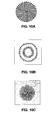
- FIGs. 8 and 9 a novel, inventive and very surprising effect is created by using stacked magnets 801 and 802 to form a toroidal parabolic reflector were two ring-shaped magnets of different radii are stacked on the top of each other.
- the resulting magnetic field illustrated in part by lines 803 is very different than using a single magnet.
- Magnetic lines near corners of the top magnet are bent down under influence of lower magnet.
- magnetic particles 804 nearby the corners of the upper magnet appear to be in the area of the field where the field intensity is large enough to provide precise concave particles alignment along the lines of applied magnetic field.
- the flakes 805 are shown to be concave oriented intermediate the outside edge and the centre.
- the flakes are dispersed in an ink 806 on a substrate 807.
- the magnets are ring-shaped, as shown in this figure, resulting printed image looks like a bright ring under a single light source. Under skylight it is a wide blue ring. Under illumination of several light sources the print looks like a set of rings equal in quantity to the number of surrounding light sources as shown in the photograph in FIG. 9 .
- This embodiment functions as a light detector, wherein the image shows the viewer a number of rings corresponding to the number of physically separate light sources that are reflected from the image. That is, for example if three light sources illuminate the image, three separate rings are visible, if n light sources are illuminate the image, n rings are visible, n being a positive integer.
- the thickness, dimensions, and strength of the magnets can vary depending upon the particular desired image. For example the stacked magnets may be of same thickness and strength, having different diameters, or alternatively one or more parameters may be varied.
- FIGs. 10A 10B , 11, 12, and 13A Examples of such images are shown in FIGs. 10A 10B , 11, 12, and 13A .
- the spiral linear image of FIG. 10A printed in the presence of a torus-shaped field, has an appearance shown in FIG. 10B .
- FIG. 10C The same spiral-like image in FIG. 10A , when printed with the funnel-shaped field, has an appearance ( FIG.10C ) that is very different from the image shown in FIG. 10B .
- the illusive image shown in FIG. 11 has a different appearance shown in FIG. 12 after printing in an applied torus-shaped field.
- the torus-shaped magnetic filed creates the illusion of a ripple in the image.
- FIG. 13B Another linear illusive image is shown in FIG. 13B wherein printing is performed in the cone-shaped field enhancing the optical illusive features in FIG. 13B .
- FIGs. 3 through 13B share radial symmetry.
- flakes are aligned in rings wherein flakes along a given ring form a same angle with the substrate upon which their edge rests and adjacent rings have flakes forming different angles with the substrate.
- flakes in a given ring have planar surfaces which intersect the plane of an adjacent flake. This is clearly seen in FIG. 14 .
- FIG. 14 (not to scale, wherein large flakes are used for illustrative purposes) a computer drawing is shown of the flake arrangement in the image of the cone, shown for example, in FIG. 7A .
- each ring of flakes R1, R2 to Rn has flakes along that ring which make a unique same angle with the planar substrate.
- the flakes in the outer ring R1 are all tilted a same angle with respect to the substrate, and the flakes within ring R2 make a slightly steeper same angle with the substrate, thus, the angle increases as one moves from ring R1, to R2, to Rn.
- the flakes that follow any given ring i.e. R1
- all lie on a circle of a particular diameter and because the flakes have planar faces; by definition, the planes defining their faces intersect with their closest neighboring flakes on lying on the same circle.
- flakes 280a and 280b have flat planar faces, wherein the planes intersect.
- FIG. 15 an illustration of the same cone of Figure 14 is shown wherein a cross-section through the middle of the structure is shown in an otherwise perspective view to illustrate the flake alignment.
- the orientation of the flakes, or tilt with respect to the substrate is shown to follow the field lines, created by a magnet (not shown) beneath the substrate.
- the flakes are shown to be substantially square, but in practice, the shapes of the flakes are likely to vary greatly unless flakes of a square or hexagon or other specific shape are used.
- FIG. 16 the axial-symmetric cone-shaped alignment of magnetic particles dispersed in thin layer of the ink is shown.
- the cross section of a magnetic field 160 is illustrated with field lines 162, but in reality, these lines form sheets of lines along which the flakes become oriented.
- Magnetically orientable flakes 163 are shown disposed in concentric rings within an ink medium 164, wherein flakes disposed in each of the rings following the field lines forms a different angle with the substrate 165 wherein the angle increases toward the centre.
- the gap 166 in the drawing is for illustrative purposes only so that the angle of the flakes with respect to the substrate can be more readily be seen.
- FIG. 17 the cone-shaped alignment of magnetic particles 173, dispersed in thin layer of ink vehicle 172, supported on a sheet 171 is shown.
- Lines 174 normal to the particles surfaces are drawn for illustrative purposes only, to show the relationship of angles normal (hereafter referred to as "normals") to the surface of the flakes, wherein the lines normal to the surfaces converge at points defining an imaginary oval area 175 where the normals converge.
- FIG. 19 a drawing is shown illustrating the cone-shaped alignment of magnetic particles 196 in the cone-shaped magnetic field resulting from disposing a cone-shaped magnet 193 above the top of the substrate.
- the particles or flakes 196 in an ink 192 are oriented with the magnetic field lines 195.
- Reference numeral 194 illustrates a cross section of the magnetic field from the conical magnet 193.
- the flakes are oriented in concentric circles wherein flakes following each circle or ring form a same angle with the substrate and wherein flakes in different rings form different angles with the substrate.
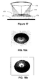
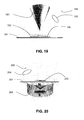
- FIG. 20 An alternative embodiment is shown in FIG. 20 wherein a cone-shaped alignment of magnetic particles in a cone-shaped magnetic field is provided by disposing a funnel-shaped magnet 202 underneath the substrate 201. Magnetic particles 205 in an ink vehicle (not shown) are printed upon the paper substrate 201. The cross section of the magnetic field is illustrated by reference numeral 203 and magnetic particles 205 follow the magnetic field lines 204. Since the field lines 204 propagate through the entire region of the substrate, ink applied to a circular regions carrying the flakes therewithin become aligned. Thus, the circle of flakes 205 disposed in the magnetic field, once aligned in the field, have the visual effect of viewing a cone shaped object. This is captured by the photographs in FIGs. 21A and 21B which show the cone-shaped print tilted toward the observer 1 and away from the observer 2.
- FIG. 20B illustrates the funnel-shaped alignment of magnetic platelets 209, dispersed in a vehicle comprising a thin layer of ink 207, with surfaces normal 208 to the particles shown.
- FIG. 20C shows an alternative embodiment wherein a funnel shaped alignment of magnetic platelets 236 is provided by a spherical or ball shaped magnet 233, disposed under a paper substrate 231.
- the platelets 236 following the field lines 235 are disposed in an ink vehicle 230. When the ink is cured the flakes become fixed in the position shown.
- FIG. 22 is a cut away partial view illustrating the alignment of diffractive magnetic particles 220 in an axial-symmetric cone-shaped magnetic field.
- a preferred orientation of the grooves of the particles is in the direction of the center of the cone.
- diffractive platelets behave as any other magnetic particles; they become oriented along the lines of the applied magnetic field.
- flat magnetic platelets dispersed in a wet ink vehicle align themselves by a longest diagonal in the direction of magnetic lines wherein diffractive platelets 220 align themselves with their grooves defining the diffractive structure or grating along the direction of the magnetic field lines.
- Axial-symmetric alignment of diffractive particles creates a silver-like region surrounded by a rainbow coloured border or generates different coloured rings in the print.
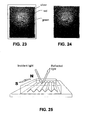
- FIGs. 23 and 24 are photographs of the axial-symmetric print containing magnetic diffractive particles and tilted toward the observer.
- the flat magnetic platelets dispersed in a wet ink vehicle on the surface of a substrate, orient themselves along magnetic lines of an applied magnetic field by their largest diagonals.
- diffractive magnetic platelets orient themselves in the same conditions along magnetic lines by direction of their grooves as shown in the FIG. 25 .
- Each particle reflects and disperses the incident light in only one particular narrow direction.
- Fresnel structures such as Fresnel reflectors.
- the conical structures and funnel-like structures described heretofore form convex and concave Fresnel reflectors.
- Fresnel absorbing structures can be made.
- reflective flakes Fresnel reflectors can be printed upon a substrate.
- Such Fresnel structures have applications as beam steering devices, for various wavelengths of electromagnetic radiation, in optical and other domains; for example as printable focusing reflectors for antennas.
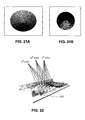
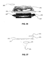
- FIG 26 an illustration is shown wherein an axial-symmetric hemisphere-shaped alignment of magnetic particles 263 dispersed in thin layer of the ink 264 forms a printed convex Fresnel mirror.
- the cross-section 261 of the magnetic field and lines of the field 262 emanating from the magnet 266 are shown to propagate through the substrate 265.
- the required magnetic field is achieved by rotating the magnet 266 in the direction of the arrow 267.
- the Fresnel-like reflective structure formed by the magnetically aligned reflective flakes 273 is clearly illustrated in FIG. 27 , wherein imaginary lines 274 shown in the Figure, normal to the surfaces of the flakes supported by the substrate 271 in an ink vehicle 272 are shown to intersect a central line normal to the most central flake.
- Reference numeral 275 indicates imaginary rays projecting through the flakes or mirrors 273.
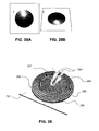
- FIGs. 28A and 28B Photographs of hemispherical convex mirrors are shown in FIGs. 28A and 28B wherein in FIG. 28A the photo is tilted with its upper edge toward the observer, and in FIG. 28B the photo is tilted with its upper edge away from the observer.
- the image formation in a printed convex Fresnel mirror is essentially the same as in conventional convex mirrors without compensation for their spherical aberration.
- FIG. 29 an isometric view is shown of the axial-symmetric convex alignment of diffractive magnetic particles 292 dispersed in the layer of the ink.
- Flat particles can replace the diffractive particles.
- the particles 292 are applied to a substrate, for example a paper substrate 291.
- the regions 293 are devoid of particles for the purposes of illustration.
- Region 294 depicts the radial direction of the grooves of the particles.
- Reference numeral 295 denotes the area with rotation of the particles around their normals and with their tilt to the substrate, wherein 296 illustrates an area with circular orientation of the grooves and the maximum tilt of the particles plane to the substrate.
- the platelets 292 When the diffractive platelets 292 are placed in the magnetic field, the platelets 292 become oriented with their grooves along lines of applied magnetic field.
- the particles in the region around the center axis of the print 297 are parallel with their planes to the surface of the substrate. Many particles but not all in this region are directed with their grooves toward the center axis of the print.
- the size of this radial alignment region is relatively small and depends upon dimensions of the magnetic field applied to the print. It may be approximately 2/3 of the width of the magnet (in case if the flat permanent magnet was used there).
- the direction of the grooves and layout of the particles 292 undergo through significant changes with a change of a distance from the center axis.
- the second area of the print adjacent to the area of radial alignment of the grooves and surrounding it, contains the particles that rotate around their normals, i.e. lines normal to the surface of the particles as shown in FIG. 30 , and tilt their planes with respect to the substrate. The particles in the second area rotate around their normals until the grooves become aligned along a circle forming an area of the circular orientation. With the increase in the distance from the center, all particles in this area are circularly oriented. Their tilt to the substrate is at the highest angle.
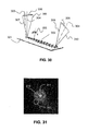
- FIG. 30 the position and alignment of diffractive particles 302 in a single radial line of particles dispersed in the layer of the ink deposited on a substrate 301, is shown.
- a line normal to the particle surface 303 in the first area is almost perpendicular to the substrate.
- the direction between the orders of diffraction 306 is at 90° to the direction of the particles' line.
- the particles incrementally rotate around their normals simultaneously tilting on the substrate with their normals directed toward outside of the print.
- the direction between diffractive orders rotates as well with the rotation of the particles. When rotation of the particles around their normals achieves 90°, the grooves become oriented along a circle.
- the particles are tilted on the substrate with their normals directed toward outside of the print. Diffractive orders are also tilted and radially oriented.
- the direction of the k th order of diffraction of particles nearby the center of the print is shown by reference numeral 307; the direction of the k th order of diffraction particles in the area of the circular alignment is shown by reference numeral 308; the direction of the m th order of diffraction of particles nearby the center of the print is shown by reference numeral 309; and, the direction of the m th order of diffraction of particles nearby the center of the print is shown by reference numeral 310.
- FIG. 31 is a photograph of the printed convex Fresnel mirror made with diluted ink on a black background.
- a central silver-like area 311 is shown with grooves of the particles shown with a radial orientation. Adjacent thereto is a rainbow like region 312 with a rotation of the grooves yielding strong vibrant colours; the outer region 313 shows rainbow like weak colours.
- a rainbow-like ring surrounds the silver area with a radial orientation of the grooves. The particles in this rainbow-coloured area rotate around their normals lying relatively flat on the substrate.
- the grooves of the particles change their direction with the rotation and the diffraction of the light begins to generate a rainbow of colours.
- a tilt of the particles relative to the surface of the substrate in the outer region 313 causes change of direction of the light reflected from the mirror surface.
- the observer is not able to see reflected light rays in this area because the rays are directed to the bottom of the page. Only a few diffractive orders can be seen generating poor rainbow colours.
- the print was fabricated by coating a substrate with a black background with a flood layer of the ink containing 5% of flat magnetic particles having averaged size of 20 micrometers and the diffractive grating frequency of 1500 lines/mm.
- the thickness of the printed layer was close to 9 micrometers.
- the substrate with the wet ink was placed on the top of a spinning (3" x 1.25" x ⁇ 0.375">) permanent magnet.
- the ink was cured in UV light after alignment of the particles was completed.
- Reference numeral 321 denotes the cross section of the field having lines 322 which emanate from the magnet 326 which is rotated in the direction of the arrow 327.
- FIG. 33 is a drawing which illustrates a concave-shaped alignment of magnetic diffractive particles 333 having a grating in the form of grooves therein dispersed in thin layer of ink vehicle 332, with lines normal to the particles surfaces 334.
- An area of spherical aberration 335 is shown just below where the flakes converge at a focal point 336.
- FIG. 34A, 34B, and 34C are photographs of the prints with hemisphere-shaped alignment. More particularly FIG. 34A is a photograph tilted with its upper edge toward the observer; photograph 34B is tilted with its upper edge away from the observer; and, FIG. 34C shows a shadow of the photographer reflected from the printed mirror.
- the image formation in the printed concave Fresnel mirror is essentially the same as in conventional concave mirrors without compensation for their spherical aberration.
- the mirrors can be compensated to reduce their aberration by correct selection of the shape of applied magnetic field and its intensity, distance between the magnet and the wet ink, ink viscosity and magnetic properties of dispersed particles.
- FIG. 35 is a plan view of the axial-symmetric concave-shaped alignment of diffractive magnetic particles dispersed in the layer of the ink, similar in many respects to FIG. 29 .
- the substrate 351 is coated with diffractive particles 352 in an ink solution (not shown).
- An area 353 of the print is devoid of particles for the purposes of illustration only.
- a region 354 shows the radial direction of the grooves of the particles.
- 355 is a region with rotation of the particles around their normals (i.e. lines normal to the particle faces) and with their tilt to the substrate; and 356 depicts a region with circular orientation of the grooves and the maximum tilt of the particles plane to the substrate.
- a preferred orientation of the grooves of the particles is in the direction of the center of the cone.
- diffractive platelets 352 Upon being exposed to the magnetic field, diffractive platelets 352 become oriented with their grooves along lines of applied magnetic field.
- the particles in the region around the center axis of the print are parallel to the surface of the substrate. Many particles but not all in this region are directed with their grooves toward the center axis of the print. The size of this region is small, however depends on dimensions of the magnetic field applied to the print.
- Direction of the grooves and layout of the particles undergo through significant changes with the change of distance from the center axis.
- the second area of the print adjacent to the area of radial alignment of the grooves and surrounding it, contains the particles that rotate around their normals as shown in FIG.36 and tilt their planes with respect to the substrate.
- the particles in the second area rotate around their normals until the grooves become align along the circle. With the growth of the distance from the center, all particles in this area are circularly oriented. Their tilt to the substrate is at highest angle.
- FIG. 36 illustrates position and alignment of diffractive particles 362 in a single radial line of the particles dispersed in the layer of the ink.
- the line normal 364 to the particle surface in the first area is almost perpendicular to the substrate 361.
- Direction between the orders of diffraction is at 90° to the direction of the particles' line.
- the particles incrementally rotate around their normals simultaneously tilting on the substrate with their normals directed toward outside of the print.
- Direction between diffractive orders 365 rotates as well with the rotation of the particles. When rotation of the particles around their normal achieves 90° the grooves become oriented along a circle. The particles are tilted on the substrate with their normals directed toward outside of the print.
- the direction f the k th order of diffraction of particles nearby the center of the print is denoted by reference numeral 366; the direction of the k th order of diffraction particles in the area of the circular alignment; the direction of the m th order of diffraction of particles nearby the center of the print is denoted by 368; and the direction of the m th order of diffraction of particles nearby the center of the print is denoted by 369.
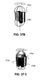
- FIG. 37F is a printed image of a hemisphere wherein the entire image is coated with alignable pigment flakes. After alignment of flakes as will be explained, the hemisphere is formed.
- the printed image of the hemisphere shown in FIG. 37F appears as the image shown in FIG. 37G as the substrate is tilted or the light source varied. As the image is tilted from the normal to the left about a vertical axis through the centre, the bright hemisphere which appears much like a ball, rolls with a change of tilt angle.
- the hemisphere in FIG. 37F is capable or appearing to move in any x-y direction, depending upon the angle of tilt.
- tilting the image about the x or y axis results in the appearance of movement.
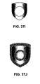
- the shield in FIG. 37J uses a combination of a rolling bar and hemisphere effects to provide very interesting combination of effects wherein the shield and hemisphere appear to project out of the page.
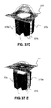
- This is produced in a two stage process, wherein the substrate is first coated with a magnetic coating and a hemisphere is formed and cured as in FIG. 37H .
- a second coating is applied through a mask or stencil to form the coating of FIG. 37I ensuring that no additional coating material covers the hemisphere.
- This second coating is placed in a magnetic field so as to produce a rolling bar.
- the method of forming the dynamic or kinematic hemispherical image described above is more complex than the method of forming the rolling bar.
- the magnet 370a shown in FIG. 37A illustrates a field line above and below the magnet, forming two loops. This diagram purposely only shows these two lines, however, there is essentially a front of lines that would be generated parallel to these lines, spanning the entire magnet.
- the magnet 370a, 370b in FIG. 37B is shown during its rotation around vertical axis at different periods of time. Part of the magnet in FIG. 37B is cut away to illustrate some of the field lines.
- FIG. 37C it is clear that the field extending above magnets in 370a, 370b, 370c is dome shaped, as is the magnetic field extending below.
- a print of a hemispherical kinematic image is formed as in 37E by disposing the coated substrate 377 with fluid ink in the dome shaped magnetic field, just above the magnets as shown in FIG. 37D or with greater separation from the magnets and supported toward the middle of the field while the magnets are spinning.
- the velocity at which the magnets or image are relatively rotated is approximately 120 rpm.
- the image is then removed from the region of the field and is cured.
- the rotation velocity of the magnets can be slower or faster than 120 rpm, depending on the particles magnetic properties and viscosity of the ink vehicle. If the velocity is too slow however, the quality of the image will degrade.
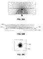
- FIG. 38A is an illustration of an alternative embodiment similar but inverted to the image shown in FIG. 37F .
- a simulated magnetic field from a hemispherical magnet is shown in FIG. 38A . This is the shape of the field that created the image shown in FIG. 38C .
- the North pole of the magnet is on the top and the particles are aligned concentrically in a funnel-like fashion.
- the field 194 in FIG. 38B is shown and flakes 193 in a carrier 192 disposed upon substrate 191 are aligned in a funnel like orientation following the field lines.
- this field generated a bright kinematic spot 192 in the middle of the image 191; and the funnel-like alignment of flakes generated a dark kinematic spot in the middle of the image.
- the fields shown and described are formed from permanent magnets, electric fields or electro-magnetic fields can be used in many embodiments.
- the field and the particles must be compatible so that the particles are capable of being oriented by the particular field.
- the particles may be diffractive, and/ or may be color shifting.
- platelet-like magnetic micro-flakes with a rectangular low-modulated low-frequency grating for fabrication of the magnetic ink for printing of images with optical effects may be utilized.
- flat particles of reflective magnetic pigment being dispersed in non-cured paint or ink vehicle, align themselves along lines of applied magnetic field with their longest diagonals; and diffractive particles, being dispersed in a non-cured paint or ink vehicle align themselves along their grooves in the direction of magnetic lines of applied field because demagnetization of a single particle is smaller along the grooves rather across them.
- This phenomenon relates to the cross-sectional thickness of a magnetic particle in different directions: it is smaller along the grooves and larger across them. Specular reflectance of the incident light by diffractive pigments is not high because of specifics of their surface morphology. When printed, the pigment shows diffractive colors under a single or multiple light sources and under the sunlight. However, there is very little color on the print under a dimmed light or under skylight.
- Another aspect of this invention is a pigment that combines two particular features of reflective and diffractive pigments: high reflectivity without noticeable diffractive colors and ability to align with grooves along the lines of an applied magnetic field.
- the pigment has a microstructure with a low-modulated square diffractive grating at a small frequency.
- the frequency can be in the range of 2 lines/mm to 500 lines/mm more preferably in the range of 50 lines/mm to 150 lines/mm.
- Modulation of the grating varies in the range of 20 nm to 1000nm (more preferably in the range of 30 nm to 200 nm).
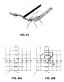
- This microstructured pigment in accordance with this invention can be fabricated from a microstructured magnetic material covered with organic or inorganic protective coating or from micro structured polymer substrate coated with a magnetic material. More preferably microstructured pigment can be fabricated from microstructured magnetic material enclosed between two layers of a reflective material. An exemplary embodiment of the structure is shown in Fig. 41 .
- Multi-layered structure MgF2/Al/Ni/Al/MgF2 was vacuum-deposited on the top of a polyester rectangular grating similar to shown in Fig. 39 .
- the widths of the hills and the valleys of the grating were 7 microns.
- the height of the hills was 80nm.
- the material was stripped off the embossed substrate and converted to microflakes with the average size of 24 microns.
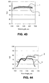
- Results in FIGs. 42a and 42b show that the sample of low-modulated low-frequency rectangular grating generates barely visible diffractive colors when measurements direction is across the grooves and no diffractive colors (not shown in the plot) at all when viewed along the grooves.
- the direction across the grooves is the most favorable for formation of diffractive effects.
- Standard 1500 lines/mm sinusoidal diffractive grating shows ( Fig. 42a and b , 2 ) has a very large color trajectory when viewed in this direction.
- the foils sample with the low-frequency grating has a silver-like appearance. There is no color peaks on the curves of reflectance neither along the grooves nor across them. On the contrary, the sample of high-frequency foil shows presence of reflectance peaks generated by diffraction of incident light.
- the grating frequency is low enough, for example less than 200 lines / mm and preferably less than 100 lines / mm, no diffractive effects are seen by the human eye, however this grating advantageously allows alignment along the grating lines.
- the grating depth is less than 100 nm.
- flakes used in the images described in the embodiments heretofore are shaped in hexagonal shapes, which allows for a greater packing density of the flakes within the image and also which advantageously provides flakes which are uniform.
- a description of manufacturing shaped flakes is found in United States published application 20060035080 .
Applications Claiming Priority (4)
| Application Number | Priority Date | Filing Date | Title |
|---|---|---|---|
| US66885205P | 2005-04-06 | 2005-04-06 | |
| US11/313,165 US7604855B2 (en) | 2002-07-15 | 2005-12-20 | Kinematic images formed by orienting alignable flakes |
| US77708606P | 2006-02-27 | 2006-02-27 | |
| EP06007199.0A EP1710756B1 (fr) | 2005-04-06 | 2006-04-05 | Dispositifs optiques modifiant l'apparence de façon dynamique imprimés dans un champ magnétique formé comprenant des structures de Fresnel imprimables |
Related Parent Applications (3)
| Application Number | Title | Priority Date | Filing Date |
|---|---|---|---|
| EP06007199.0A Division EP1710756B1 (fr) | 2005-04-06 | 2006-04-05 | Dispositifs optiques modifiant l'apparence de façon dynamique imprimés dans un champ magnétique formé comprenant des structures de Fresnel imprimables |
| EP06007199.0A Division-Into EP1710756B1 (fr) | 2005-04-06 | 2006-04-05 | Dispositifs optiques modifiant l'apparence de façon dynamique imprimés dans un champ magnétique formé comprenant des structures de Fresnel imprimables |
| EP06007199.0 Division | 2006-04-05 |
Publications (4)
| Publication Number | Publication Date |
|---|---|
| EP2325677A2 true EP2325677A2 (fr) | 2011-05-25 |
| EP2325677A3 EP2325677A3 (fr) | 2013-04-03 |
| EP2325677B1 EP2325677B1 (fr) | 2018-06-06 |
| EP2325677B8 EP2325677B8 (fr) | 2018-07-18 |
Family
ID=36754093
Family Applications (3)
| Application Number | Title | Priority Date | Filing Date |
|---|---|---|---|
| EP10011762.1A Active EP2306222B8 (fr) | 2005-04-06 | 2006-04-05 | Dispositifs optiques à changement d'apparence dynamique (DACOD) imprimés dans un champ magnétique formé incluant des structures Fresnel imprimables |
| EP06007199.0A Active EP1710756B1 (fr) | 2005-04-06 | 2006-04-05 | Dispositifs optiques modifiant l'apparence de façon dynamique imprimés dans un champ magnétique formé comprenant des structures de Fresnel imprimables |
| EP10011761.3A Active EP2325677B8 (fr) | 2005-04-06 | 2006-04-05 | Dispositifs optiques à changement d'apparence dynamique (DACOD) imprimés dans un champ magnétique formé incluant des structures Fresnel imprimables |
Family Applications Before (2)
| Application Number | Title | Priority Date | Filing Date |
|---|---|---|---|
| EP10011762.1A Active EP2306222B8 (fr) | 2005-04-06 | 2006-04-05 | Dispositifs optiques à changement d'apparence dynamique (DACOD) imprimés dans un champ magnétique formé incluant des structures Fresnel imprimables |
| EP06007199.0A Active EP1710756B1 (fr) | 2005-04-06 | 2006-04-05 | Dispositifs optiques modifiant l'apparence de façon dynamique imprimés dans un champ magnétique formé comprenant des structures de Fresnel imprimables |
Country Status (10)
| Country | Link |
|---|---|
| US (3) | US8343615B2 (fr) |
| EP (3) | EP2306222B8 (fr) |
| JP (2) | JP5518279B2 (fr) |
| KR (1) | KR101300030B1 (fr) |
| CN (3) | CN103085587B (fr) |
| BR (1) | BRPI0601371B1 (fr) |
| CA (1) | CA2541568C (fr) |
| HK (2) | HK1185043A1 (fr) |
| RU (1) | RU2429083C2 (fr) |
| TW (1) | TWI402106B (fr) |
Cited By (27)
| Publication number | Priority date | Publication date | Assignee | Title |
|---|---|---|---|---|
| WO2015086257A1 (fr) | 2013-12-13 | 2015-06-18 | Sicpa Holding Sa | Procédé de production de couches à effets |
| EP2965920A1 (fr) | 2014-07-09 | 2016-01-13 | Sicpa Holding Sa | Fils et bandes de sécurité magnétique optiquement variables |
| WO2016016028A1 (fr) | 2014-07-30 | 2016-02-04 | Sicpa Holding Sa | Procédés commandés par courroie permettant de produire des couches à effet optique |
| WO2016193252A1 (fr) | 2015-06-02 | 2016-12-08 | Sicpa Holding Sa | Procédés de fabrication de couches à effet optique |
| WO2017064052A1 (fr) | 2015-10-15 | 2017-04-20 | Sicpa Holding Sa | Assemblages magnétiques et procédés de production de couches à effet optique comprenant des particules de pigment magnétiques ou magnétisables non sphériques orientées |
| EP3178569A1 (fr) | 2016-06-29 | 2017-06-14 | Sicpa Holding Sa | Procédés et dispositifs pour produire des couches à effet optique au moyen d'un photomasque |
| WO2017148789A1 (fr) | 2016-02-29 | 2017-09-08 | Sicpa Holding Sa | Appareils et processus de production de couches à effet optique comprenant des particules de pigment magnétiques ou magnétisables non sphériques orientées |
| WO2018054819A1 (fr) | 2016-09-22 | 2018-03-29 | Sicpa Holding Sa | Appareils et procédés de production de couches à effet optique comprenant des particules de pigment magnétiques ou magnétisables non sphériques orientées |
| US10052903B2 (en) | 2014-07-29 | 2018-08-21 | Sicpa Holding Sa | Processes for in-field hardening of optical effect layers produced by magnetic-field generating devices generating concave field lines |
| US10166808B2 (en) | 2013-12-11 | 2019-01-01 | Sicpa Holding Sa | Optically variable security threads and stripes |
| WO2019038370A1 (fr) | 2017-08-25 | 2019-02-28 | Sicpa Holding Sa | Ensembles et procédés de production de couches à effet optique comprenant des particules de pigment magnétiques ou magnétisables aplaties non sphériques orientées |
| WO2019038371A1 (fr) | 2017-08-25 | 2019-02-28 | Sicpa Holding Sa | Ensembles et procédés de production de couches à effet optique comprenant des particules de pigment magnétiques ou magnétisables orientées non sphériques aplaties |
| WO2019038369A1 (fr) | 2017-08-25 | 2019-02-28 | Sicpa Holding Sa | Ensembles et procédés de production de couches à effet optique comprenant des particules de pigment magnétiques ou magnétisables orientées non sphériques aplaties |
| US10279618B2 (en) | 2013-08-05 | 2019-05-07 | Sicpa Holding Sa | Magnetic or magnetisable pigment particles and optical effect layers |
| WO2019141453A1 (fr) | 2018-01-17 | 2019-07-25 | Sicpa Holding Sa | Procédés de fabrication de couches à effet optique |
| WO2019215148A1 (fr) | 2018-05-08 | 2019-11-14 | Sicpa Holding Sa | Ensembles et appareils magnétiques et procédés de production de couches à effet optique comprenant des particules de pigment magnétiques ou magnétisables non sphériques orientées |
| WO2020025482A1 (fr) | 2018-07-30 | 2020-02-06 | Sicpa Holding Sa | Ensembles et procédés de production de couches à effet optique comprenant des particules de pigment orientées magnétiques ou magnétisables, non sphériques et aplaties |
| WO2020025218A1 (fr) | 2018-07-30 | 2020-02-06 | Sicpa Holding Sa | Procédés de production de couches à effets optiques |
| WO2020052862A1 (fr) | 2018-09-10 | 2020-03-19 | Sicpa Holding Sa | Procédés de production de couches à effet optique comprenant des particules de pigment magnétiques ou magnétisables non sphériques orientées |
| WO2020173693A1 (fr) | 2019-02-28 | 2020-09-03 | Sicpa Holding Sa | Procédé d'authentification d'une marque induite magnétiquement avec un dispositif portable |
| WO2020173696A1 (fr) | 2019-02-28 | 2020-09-03 | Sicpa Holding Sa | Justificatif d'identité d'accès vérifiable |
| US10906066B2 (en) | 2015-11-10 | 2021-02-02 | Sicpa Holding Sa | Appartuses and processes for producing optical effect layers comprising oriented non-spherical magnetic or magnetizable pigment particles |
| WO2021239607A1 (fr) | 2020-05-26 | 2021-12-02 | Sicpa Holding Sa | Ensembles magnétiques et méthodes de production de couches à effet optique comprenant des particules de pigment magnétiques ou magnétisables lamelliformes orientées |
| WO2021259527A1 (fr) | 2020-06-23 | 2021-12-30 | Sicpa Holding Sa | Procédés de production de couches à effet optique comprenant des particules pigmentaires magnétiques ou magnétisables |
| WO2022207692A1 (fr) | 2021-03-31 | 2022-10-06 | Sicpa Holding Sa | Procédés de production de couches à effet optique comprenant des particules pigmentaires magnétiques ou magnétisables et présentant un ou plusieurs indices |
| WO2023161464A1 (fr) | 2022-02-28 | 2023-08-31 | Sicpa Holding Sa | Procédés de production de couches à effet optique comprenant des particules pigmentaires magnétiques ou magnétisables et présentant un ou plusieurs indices |
| WO2024028408A1 (fr) | 2022-08-05 | 2024-02-08 | Sicpa Holding Sa | Procédés de production de couches à effet optique comprenant des particules de pigment magnétiques ou magnétisables et présentant un ou plusieurs indices |
Families Citing this family (108)
| Publication number | Priority date | Publication date | Assignee | Title |
|---|---|---|---|---|
| US7047883B2 (en) | 2002-07-15 | 2006-05-23 | Jds Uniphase Corporation | Method and apparatus for orienting magnetic flakes |
| US7934451B2 (en) | 2002-07-15 | 2011-05-03 | Jds Uniphase Corporation | Apparatus for orienting magnetic flakes |
| US11230127B2 (en) | 2002-07-15 | 2022-01-25 | Viavi Solutions Inc. | Method and apparatus for orienting magnetic flakes |
| US9458324B2 (en) | 2002-09-13 | 2016-10-04 | Viava Solutions Inc. | Flakes with undulate borders and method of forming thereof |
| US7674501B2 (en) | 2002-09-13 | 2010-03-09 | Jds Uniphase Corporation | Two-step method of coating an article for security printing by application of electric or magnetic field |
| US20070224398A1 (en) * | 2006-03-21 | 2007-09-27 | Jds Uniphase Corporation | Brand Protection Label With A Tamper Evident Abrasion-Removable Magnetic Ink |
| US8025952B2 (en) | 2002-09-13 | 2011-09-27 | Jds Uniphase Corporation | Printed magnetic ink overt security image |
| TWI402106B (zh) | 2005-04-06 | 2013-07-21 | Jds Uniphase Corp | 印記於含有可印記菲涅耳結構之成型磁場中之動態外觀變化光學裝置(dacod) |
| DK1745940T3 (en) * | 2005-07-20 | 2014-03-03 | Jds Uniphase Corp | Two-step FOR COATING OF AN OBJECT OF SAFETY PRESSURE |
| JP5259946B2 (ja) * | 2005-11-18 | 2013-08-07 | ジェイディーエス ユニフェイズ コーポレーション | 光学効果の印刷のための磁性板 |
| CA2570965A1 (fr) | 2005-12-15 | 2007-06-15 | Jds Uniphase Corporation | Dispositif de securite a caracteristiques metameriques utilisant des flocons de pigments diffractifs |
| AU2007200128B8 (en) | 2006-01-17 | 2013-02-07 | Viavi Solutions Inc. | Apparatus for orienting magnetic flakes |
| US10343436B2 (en) | 2006-02-27 | 2019-07-09 | Viavi Solutions Inc. | Security device formed by printing with special effect inks |
| AU2007238799B2 (en) * | 2006-04-11 | 2011-11-24 | Viavi Solutions Inc. | Security image coated with a single coating having visualy distinct regions |
| TWI437059B (zh) | 2006-07-12 | 2014-05-11 | Jds Uniphase Corp | 壓印一經硬化及場配向之特效薄片之塗層及藉此形成之圖像 |
| EP1990208A1 (fr) * | 2007-05-10 | 2008-11-12 | Kba-Giori S.A. | Dispositif et procédé pour transférer magnétiquement un indice vers une composition de revêtement appliquée à un substrat |
| US7719752B2 (en) | 2007-05-11 | 2010-05-18 | Qualcomm Mems Technologies, Inc. | MEMS structures, methods of fabricating MEMS components on separate substrates and assembly of same |
| AU2008219354B2 (en) | 2007-09-19 | 2014-02-13 | Viavi Solutions Inc. | Anisotropic magnetic flakes |
| AU2008252069A1 (en) * | 2007-12-05 | 2009-06-25 | Jds Uniphase Corporation | Reinforced glitter |
| US9371923B2 (en) | 2008-04-04 | 2016-06-21 | Correlated Magnetics Research, Llc | Magnetic valve assembly |
| US8576036B2 (en) | 2010-12-10 | 2013-11-05 | Correlated Magnetics Research, Llc | System and method for affecting flux of multi-pole magnetic structures |
| US9202616B2 (en) | 2009-06-02 | 2015-12-01 | Correlated Magnetics Research, Llc | Intelligent magnetic system |
| US9105380B2 (en) | 2008-04-04 | 2015-08-11 | Correlated Magnetics Research, Llc. | Magnetic attachment system |
| US7800471B2 (en) | 2008-04-04 | 2010-09-21 | Cedar Ridge Research, Llc | Field emission system and method |
| US8368495B2 (en) | 2008-04-04 | 2013-02-05 | Correlated Magnetics Research LLC | System and method for defining magnetic structures |
| US8023191B2 (en) * | 2008-05-07 | 2011-09-20 | Qualcomm Mems Technologies, Inc. | Printable static interferometric images |
| US8937521B2 (en) | 2012-12-10 | 2015-01-20 | Correlated Magnetics Research, Llc. | System for concentrating magnetic flux of a multi-pole magnetic structure |
| US8917154B2 (en) | 2012-12-10 | 2014-12-23 | Correlated Magnetics Research, Llc. | System for concentrating magnetic flux |
| TWI443612B (zh) * | 2009-04-07 | 2014-07-01 | Sicpa Holding Sa | 受壓變色保密元件 |
| US9404776B2 (en) | 2009-06-02 | 2016-08-02 | Correlated Magnetics Research, Llc. | System and method for tailoring polarity transitions of magnetic structures |
| US8704626B2 (en) | 2010-05-10 | 2014-04-22 | Correlated Magnetics Research, Llc | System and method for moving an object |
| US9711268B2 (en) | 2009-09-22 | 2017-07-18 | Correlated Magnetics Research, Llc | System and method for tailoring magnetic forces |
| GB201001603D0 (en) * | 2010-02-01 | 2010-03-17 | Rue De Int Ltd | Security elements, and methods and apparatus for their manufacture |
| TWI540896B (zh) * | 2010-11-15 | 2016-07-01 | 國立研究開發法人科學技術振興機構 | 印刷有視錯覺影像的媒體及記錄有電腦可讀取的影像資料之記錄媒體 |
| US8945688B2 (en) * | 2011-01-03 | 2015-02-03 | General Electric Company | Process of forming a material having nano-particles and a material having nano-particles |
| DK2484455T3 (en) * | 2011-02-07 | 2015-03-09 | Sicpa Holding Sa | A device for displaying a dynamic visual movement effect and process for producing same |
| US8702437B2 (en) | 2011-03-24 | 2014-04-22 | Correlated Magnetics Research, Llc | Electrical adapter system |
| DE102011015837A1 (de) * | 2011-04-01 | 2012-10-04 | Giesecke & Devrient Gmbh | Optisch variabeles Sicherheitselement mit optisch variabeler Farbschicht |
| WO2012142306A2 (fr) | 2011-04-12 | 2012-10-18 | Sarai Mohammad | Configurations magnétiques |
| DE102011102999A1 (de) | 2011-05-24 | 2012-11-29 | Leonhard Kurz Stiftung & Co. Kg | Folie und deren Herstellungsverfahren |
| US8963380B2 (en) | 2011-07-11 | 2015-02-24 | Correlated Magnetics Research LLC. | System and method for power generation system |
| FR2979734B1 (fr) | 2011-09-02 | 2014-05-23 | Arjowiggins Security | Structure de securite comportant une structure optique reflechissante, et procede associe. |
| US8848973B2 (en) | 2011-09-22 | 2014-09-30 | Correlated Magnetics Research LLC | System and method for authenticating an optical pattern |
| CN107377333B (zh) * | 2012-01-12 | 2020-10-16 | 唯亚威通讯技术有限公司 | 带有由排列的颜料片形成的弯曲图案的物品 |
| BR112014026974B1 (pt) * | 2012-05-07 | 2020-12-08 | Sicpa Holding Sa | camada de efeito óptico, dispositivo e método para produzir a mesma, documento de segurança e uso de uma camada de sefeito óptico |
| MX353329B (es) * | 2012-06-01 | 2018-01-08 | Toppan Printing Co Ltd | Pantalla de reflexion unisometrica, portador de informacion que utiliza la pantalla de reflexion unisometrica. |
| WO2014004728A2 (fr) * | 2012-06-26 | 2014-01-03 | Roberts Mark D | Système et procédé pour authentifier un motif optique |
| US9245677B2 (en) | 2012-08-06 | 2016-01-26 | Correlated Magnetics Research, Llc. | System for concentrating and controlling magnetic flux of a multi-pole magnetic structure |
| DE102012024175A1 (de) * | 2012-12-10 | 2014-06-12 | Giesecke & Devrient Gmbh | Vorrichtung zur Untersuchung eines Wertdokuments und Verfahren zur Untersuchung eines Wertdokuments |
| AU2013372261B2 (en) | 2013-01-09 | 2017-08-24 | Sicpa Holding Sa | Optical effect layers showing a viewing angle dependent optical effect, processes and devices for their production, items carrying an optical effect layer, and uses thereof |
| AR094362A1 (es) * | 2013-01-09 | 2015-07-29 | Sicpa Holding Sa | Capas de efectos ópticos que muestran un efecto óptico que depende del ángulo de visión; procesos y dispositivos para la producción de esas capas, artículos que llevan una capa de efectos ópticos y usos de esas capas |
| EP2956514B1 (fr) * | 2013-02-14 | 2018-05-23 | Sicpa Holding Sa | Procédé d'impression d'imprimé en taille douce à caractéristiques multiples |
| CN104129153B (zh) | 2013-03-27 | 2018-06-05 | Viavi 科技有限公司 | 具有虚幻光学效应的光学装置及其制造方法 |
| KR20160002943A (ko) * | 2013-05-02 | 2016-01-08 | 시크파 홀딩 에스에이 | 보안 스레드 또는 스트라이프의 제조 방법 |
| ES2726190T3 (es) | 2013-06-14 | 2019-10-02 | Sicpa Holding Sa | Conjuntos de imán permanente para generar líneas de campo cóncavas y método para crear revestimiento de efecto óptico con los mismos (barra rodante inversa) |
| KR20150041321A (ko) * | 2013-10-08 | 2015-04-16 | 엘지이노텍 주식회사 | 자성시트 및 이를 포함하는 무선충전용 자성부재 |
| CN105980162B (zh) | 2014-02-13 | 2017-09-22 | 锡克拜控股有限公司 | 安全线和条 |
| CN109291608A (zh) | 2014-05-12 | 2019-02-01 | 唯亚威通讯技术有限公司 | 包含磁性薄片的光学可变装置 |
| US9714027B2 (en) | 2014-08-18 | 2017-07-25 | Ford Global Technologies, Llc | Methods and systems for starting an engine |
| US10183663B2 (en) | 2014-08-18 | 2019-01-22 | Ford Global Technologies, Llc | Methods and systems for starting an engine |
| FR3028801B1 (fr) | 2014-11-24 | 2021-11-19 | Arjowiggins Security | Element de securite |
| KR102177264B1 (ko) * | 2014-12-26 | 2020-11-11 | 한국전자기술연구원 | 사용자 위치 중심의 보안 필름 |
| DE102015005911A1 (de) * | 2015-05-07 | 2016-11-10 | Giesecke & Devrient Gmbh | Optisch variables Sicherheitselement |
| DE102015005969A1 (de) * | 2015-05-08 | 2016-11-10 | Giesecke & Devrient Gmbh | Optisch variables Sicherheitselement |
| EP3093156B1 (fr) * | 2015-05-12 | 2017-08-30 | U-NICA Technology AG | Support de données ayant une caractéristique magnétique d'authenticité personnalisable et procédé d'écriture de supports de données |
| US20180144664A1 (en) | 2015-07-01 | 2018-05-24 | Sicpa Holding Sa | Postage stamps |
| US10357582B1 (en) | 2015-07-30 | 2019-07-23 | Vital Vio, Inc. | Disinfecting lighting device |
| CA2993825C (fr) | 2015-07-30 | 2020-08-25 | Vital Vio, Inc. | Desinfection par diode unique |
| US10918747B2 (en) | 2015-07-30 | 2021-02-16 | Vital Vio, Inc. | Disinfecting lighting device |
| CN105599428A (zh) * | 2016-03-05 | 2016-05-25 | 郑树川 | 彩虹膜成膜的生产工艺和生产设备 |
| EP3420388A4 (fr) | 2016-04-04 | 2019-11-27 | Akonia Holographics, LLC | Égalisation de pupille |
| RS62091B1 (sr) | 2016-07-29 | 2021-08-31 | Sicpa Holding Sa | Procesi za proizvodnju slojeva sa efektom |
| PL3500374T3 (pl) | 2016-08-16 | 2021-09-27 | Sicpa Holding Sa | Sposoby wytwarzania warstw z efektem |
| MX2019002084A (es) * | 2016-08-31 | 2019-07-18 | Viavi Solutions Inc | Orientacion de hojuelas magneticamente orientables. |
| EP3507629A4 (fr) * | 2016-08-31 | 2020-05-13 | Viavi Solutions Inc. | Article à segments réfléchissants inclinés |
| US10357991B2 (en) | 2016-12-19 | 2019-07-23 | Viavi Solutions Inc. | Security ink based security feature |
| DE102017106433A1 (de) * | 2017-03-24 | 2018-09-27 | Ovd Kinegram Ag | Sicherheitselement und Verfahren zur Herstellung eines Sicherheitselements |
| CN111247465B (zh) | 2017-10-04 | 2022-05-13 | 阿科尼亚全息有限责任公司 | 梳状移位式斜交镜 |
| US11155113B2 (en) * | 2017-11-03 | 2021-10-26 | Agency For Science, Technology And Research | Holographic security element and method of forming thereof |
| US10835627B2 (en) | 2017-12-01 | 2020-11-17 | Vital Vio, Inc. | Devices using flexible light emitting layer for creating disinfecting illuminated surface, and related method |
| US10309614B1 (en) | 2017-12-05 | 2019-06-04 | Vital Vivo, Inc. | Light directing element |
| US10413626B1 (en) | 2018-03-29 | 2019-09-17 | Vital Vio, Inc. | Multiple light emitter for inactivating microorganisms |
| US10618340B2 (en) | 2018-05-16 | 2020-04-14 | Viavi Solutions Inc. | Security feature based on a single axis alignment of mirrors in a structured surface that forms a micro mirror array |
| DE102018004433A1 (de) * | 2018-06-05 | 2019-12-05 | Giesecke+Devrient Currency Technology Gmbh | Verfahren zum Herstellen eines Wertdokuments, Wertdokument und Druckvorrichtung |
| CN108682285A (zh) * | 2018-06-22 | 2018-10-19 | 孙涵 | 具有光柱变色效果的标签及其制备方法 |
| US10642214B2 (en) * | 2018-08-13 | 2020-05-05 | Viavi Solutions Inc. | Optical security device based on a surface of revolution |
| CN109118950B (zh) * | 2018-10-10 | 2021-03-02 | 苏州征之魂专利技术服务有限公司 | 一种信息防伪光断器 |
| DE102018008146A1 (de) * | 2018-10-15 | 2020-04-16 | Giesecke+Devrient Currency Technology Gmbh | Sicherheitselement mit Mikroreflektoren zur perspektivischen Darstellung eines Motivs |
| KR20210114475A (ko) | 2019-01-15 | 2021-09-23 | 시크파 홀딩 에스에이 | 광학 효과층을 생성하기 위한 공정 |
| CA3128938A1 (fr) | 2019-02-08 | 2020-08-13 | Sicpa Holding Sa | Ensembles magnetiques et procedes de production de couches a effet optique comprenant des particules de pigment magnetiques ou magnetisables orientees non spheriques aplaties |
| WO2020193009A1 (fr) | 2019-03-28 | 2020-10-01 | Sicpa Holding Sa | Ensembles magnétiques et procédés de production de couches à effet optique comprenant des particules de pigments magnétiques ou magnétisables non sphériques orientées |
| US11639897B2 (en) | 2019-03-29 | 2023-05-02 | Vyv, Inc. | Contamination load sensing device |
| CN110143076B (zh) * | 2019-05-28 | 2021-08-31 | 成都印钞有限公司 | 一种磁性光变油墨的定磁方法 |
| CN110834475A (zh) * | 2019-06-12 | 2020-02-25 | 上海麟多祈化工科技有限公司 | 一种磁控防伪数码喷头装置及使用方法 |
| US11541135B2 (en) | 2019-06-28 | 2023-01-03 | Vyv, Inc. | Multiple band visible light disinfection |
| DE102019005551A1 (de) * | 2019-08-07 | 2021-02-11 | Giesecke+Devrient Currency Technology Gmbh | Herstellverfahren für ein Sicherheitspapier und damit erhältliches Sicherheitspapier |
| US11369704B2 (en) | 2019-08-15 | 2022-06-28 | Vyv, Inc. | Devices configured to disinfect interiors |
| CN111776471B (zh) * | 2019-08-16 | 2022-07-12 | 西安印钞有限公司 | 一种景变防伪结构和防伪塑封及制备方法 |
| US11878084B2 (en) | 2019-09-20 | 2024-01-23 | Vyv, Inc. | Disinfecting light emitting subcomponent |
| KR20220088906A (ko) | 2019-10-28 | 2022-06-28 | 시크파 홀딩 에스에이 | 배향된 비-구형 자성 또는 자화성 안료 입자를 포함하는 광학 효과층을 제조하기 위한 자성 어셈블리 및 공정 |
| EP4051439B1 (fr) | 2019-10-28 | 2023-08-02 | Sicpa Holding Sa | Ensembles magnétiques et leurs procédés de production de couches à effet optique comprenant des particules pigmentaires magnétiques ou magnétisables orientées non sphériques |
| RU2748106C1 (ru) * | 2020-02-28 | 2021-05-19 | Александр Николаевич Шалыгин | Защитный элемент на основе скрытых магнитных микроструктурных образований и способ защиты изделий от подделки |
| DE102021002335A1 (de) | 2021-05-03 | 2022-12-01 | Giesecke+Devrient Currency Technology Gmbh | Optisch variables sicherheitselement und wertdokument mit dem optisch variablen sicherheitselement |
| WO2022265997A1 (fr) | 2021-06-14 | 2022-12-22 | Viavi Solutions Inc. | Élément de sécurité optique |
| CN114771090B (zh) * | 2022-03-18 | 2023-09-01 | 山东泰宝信息科技集团有限公司 | 磁性光变防伪标识印刷装置 |
| CN114701250B (zh) * | 2022-03-18 | 2023-05-26 | 山东泰宝信息科技集团有限公司 | 磁性3d光变定磁设备 |
| CN114633574A (zh) * | 2022-03-24 | 2022-06-17 | 彭亮 | 一种动态视觉立体效果的安全线或条 |
| CN115447270A (zh) * | 2022-10-24 | 2022-12-09 | 浙江雅琪诺装饰材料有限公司 | 一种用于双层墙纸的印刷装置及使用方法 |
Citations (5)
| Publication number | Priority date | Publication date | Assignee | Title |
|---|---|---|---|---|
| US20030190473A1 (en) | 2002-04-05 | 2003-10-09 | Flex Products, Inc. | Chromatic diffractive pigments and foils |
| US6692830B2 (en) | 2001-07-31 | 2004-02-17 | Flex Products, Inc. | Diffractive pigment flakes and compositions |
| US20040051297A1 (en) | 2002-07-15 | 2004-03-18 | Flex Products, Inc., A Jds Uniphase Company | Method and apparatus for orienting magnetic flakes |
| US20050106367A1 (en) | 2002-07-15 | 2005-05-19 | Jds Uniphase Corporation | Method and apparatus for orienting magnetic flakes |
| US20060035080A1 (en) | 2002-09-13 | 2006-02-16 | Jds Uniphase Corporation | Provision of frames or borders around opaque flakes for covert security applications |
Family Cites Families (186)
| Publication number | Priority date | Publication date | Assignee | Title |
|---|---|---|---|---|
| US2570856A (en) | 1947-03-25 | 1951-10-09 | Du Pont | Process for obtaining pigmented films |
| US2578590A (en) | 1948-02-25 | 1951-12-11 | Perrault Bros | Safety valve |
| DE1696245U (de) | 1955-02-14 | 1955-04-07 | Willy Bucke | Briefklammer. |
| US3011383A (en) | 1957-04-30 | 1961-12-05 | Carpenter L E Co | Decorative optical material |
| NL131828C (fr) * | 1961-05-04 | |||
| US3338730A (en) * | 1964-02-18 | 1967-08-29 | Little Inc A | Method of treating reflective surfaces to make them multihued and resulting product |
| DE1253730B (de) | 1964-06-05 | 1967-11-09 | Agfa Ag | Verfahren zum ganzen oder auszugsweisen Abdruck einer Druckform und Rotationsvervielfaelfaeltiger zur Durchfuehrung des Verfahrens |
| FR1440147A (fr) | 1965-04-15 | 1966-05-27 | Tefal Sa | Procédé de décoration, dans la masse, d'un matériau plastique translucide |
| GB1127043A (en) | 1967-01-26 | 1968-09-11 | Portals Ltd | Security papers |
| US3627580A (en) | 1969-02-24 | 1971-12-14 | Eastman Kodak Co | Manufacture of magnetically sensitized webs |
| US3633720A (en) * | 1969-09-25 | 1972-01-11 | Honeywell Inc | Alphanumeric printing device employing magnetically positionable particles |
| US3845499A (en) | 1969-09-25 | 1974-10-29 | Honeywell Inc | Apparatus for orienting magnetic particles having a fixed and varying magnetic field component |
| US3610721A (en) | 1969-10-29 | 1971-10-05 | Du Pont | Magnetic holograms |
| US3853676A (en) | 1970-07-30 | 1974-12-10 | Du Pont | Reference points on films containing curved configurations of magnetically oriented pigment |
| US3676273A (en) * | 1970-07-30 | 1972-07-11 | Du Pont | Films containing superimposed curved configurations of magnetically orientated pigment |
| IT938725B (it) * | 1970-11-07 | 1973-02-10 | Magnetfab Bonn Gmbh | Procedimento e dispositivo per otte nere disegni in strati superficiali per mezzo di campi magnetici |
| US3790407A (en) * | 1970-12-28 | 1974-02-05 | Ibm | Recording media and method of making |
| US3873975A (en) * | 1973-05-02 | 1975-03-25 | Minnesota Mining & Mfg | System and method for authenticating and interrogating a magnetic record medium |
| AU488652B2 (en) | 1973-09-26 | 1976-04-01 | Commonwealth Scientific And Industrial Research Organisation | Improvements in or relating to security tokens |
| DE2520581C3 (de) | 1975-05-09 | 1980-09-04 | Kienzle Apparate Gmbh, 7730 Villingen-Schwenningen | Anordnung zum loschbaren Aufzeichnen von Meßgrößen |
| US4011009A (en) * | 1975-05-27 | 1977-03-08 | Xerox Corporation | Reflection diffraction grating having a controllable blaze angle |
| CA1090631A (fr) | 1975-12-22 | 1980-12-02 | Roland Moraw | Methode d'identification par procede holographique ainsi que l'appareil utilise |
| US4155627A (en) * | 1976-02-02 | 1979-05-22 | Rca Corporation | Color diffractive subtractive filter master recording comprising a plurality of superposed two-level relief patterns on the surface of a substrate |
| US4099838A (en) * | 1976-06-07 | 1978-07-11 | Minnesota Mining And Manufacturing Company | Reflective sheet material |
| US4066280A (en) * | 1976-06-08 | 1978-01-03 | American Bank Note Company | Documents of value printed to prevent counterfeiting |
| DE2752895A1 (de) | 1976-12-06 | 1978-06-08 | Emi Ltd | Verfahren zur herstellung einer materialschicht, deren oberflaeche ein abtastbares muster aufweist, sowie sicherheitsdokumentensystem |
| FR2408890A1 (fr) * | 1977-11-10 | 1979-06-08 | Transac Dev Transact Automat | Procede et dispositif d'orientation et de fixation dans une direction determinee de particules magnetiques contenues dans une encre polymerisable |
| US4168983A (en) | 1978-04-13 | 1979-09-25 | Vittands Walter A | Phosphate coating composition |
| US4271782A (en) * | 1978-06-05 | 1981-06-09 | International Business Machines Corporation | Apparatus for disorienting magnetic particles |
| US4310584A (en) * | 1979-12-26 | 1982-01-12 | The Mearl Corporation | Multilayer light-reflecting film |
| US5059245A (en) | 1979-12-28 | 1991-10-22 | Flex Products, Inc. | Ink incorporating optically variable thin film flakes |
| US5569535A (en) | 1979-12-28 | 1996-10-29 | Flex Products, Inc. | High chroma multilayer interference platelets |
| US4434010A (en) * | 1979-12-28 | 1984-02-28 | Optical Coating Laboratory, Inc. | Article and method for forming thin film flakes and coatings |
| US5084351A (en) * | 1979-12-28 | 1992-01-28 | Flex Products, Inc. | Optically variable multilayer thin film interference stack on flexible insoluble web |
| US5171363A (en) * | 1979-12-28 | 1992-12-15 | Flex Products, Inc. | Optically variable printing ink |
| US5766738A (en) | 1979-12-28 | 1998-06-16 | Flex Products, Inc. | Paired optically variable article with paired optically variable structures and ink, paint and foil incorporating the same and method |
| US5135812A (en) | 1979-12-28 | 1992-08-04 | Flex Products, Inc. | Optically variable thin film flake and collection of the same |
| US4398798A (en) | 1980-12-18 | 1983-08-16 | Sperry Corporation | Image rotating diffraction grating |
| AU550965B2 (en) | 1983-10-14 | 1986-04-10 | Dow Chemical Company, The | Coextruded multi-layered articles |
| CA1232068A (fr) * | 1984-06-08 | 1988-01-26 | National Research Council Of Canada | Dispositif d'authentification interferometrique a reconnaissance de formes |
| US4543551A (en) | 1984-07-02 | 1985-09-24 | Polaroid Corporation | Apparatus for orienting magnetic particles in recording media |
| US4705300A (en) | 1984-07-13 | 1987-11-10 | Optical Coating Laboratory, Inc. | Thin film optically variable article and method having gold to green color shift for currency authentication |
| US4705356A (en) | 1984-07-13 | 1987-11-10 | Optical Coating Laboratory, Inc. | Thin film optical variable article having substantial color shift with angle and method |
| DE3446861A1 (de) | 1984-12-21 | 1986-07-10 | GAO Gesellschaft für Automation und Organisation mbH, 8000 München | Sicherheitsdokument mit darin eingelagertem sicherheitsfaden und verfahren zur herstellung und echtheitspruefung des sicherheitsdokuments |
| DE3500079A1 (de) * | 1985-01-03 | 1986-07-10 | Henkel KGaA, 4000 Düsseldorf | Mittel und verfahren zur erzeugung farbloser verdichtungsschichten auf anodisierten aluminiumoberflaechen |
| US4788116A (en) | 1986-03-31 | 1988-11-29 | Xerox Corporation | Full color images using multiple diffraction gratings and masking techniques |
| DE3617430A1 (de) | 1986-05-23 | 1987-11-26 | Merck Patent Gmbh | Perlglanzpigmente |
| US4721217A (en) * | 1986-08-07 | 1988-01-26 | Optical Coating Laboratory, Inc. | Tamper evident optically variable device and article utilizing the same |
| US4930866A (en) * | 1986-11-21 | 1990-06-05 | Flex Products, Inc. | Thin film optical variable article and method having gold to green color shift for currency authentication |
| US4779898A (en) | 1986-11-21 | 1988-10-25 | Optical Coating Laboratory, Inc. | Thin film optically variable article and method having gold to green color shift for currency authentication |
| JPH0694543B2 (ja) | 1987-01-09 | 1994-11-24 | 三菱自動車工業株式会社 | 塗 料 |
| JPS63172279A (ja) | 1987-01-12 | 1988-07-15 | Nippon Zeon Co Ltd | 静電荷像現像用トナ−の製造方法 |
| WO1988007214A1 (fr) | 1987-03-10 | 1988-09-22 | Precis (549) Limited | Materiaux reflechissant la lumiere |
| US4745617A (en) | 1987-03-27 | 1988-05-17 | Hughes Aircraft Company | Ideal distributed Bragg reflectors and resonators |
| JPS63172279U (fr) | 1987-04-27 | 1988-11-09 | ||
| JPS63172779U (fr) | 1987-05-01 | 1988-11-09 | ||
| US4923533A (en) * | 1987-07-31 | 1990-05-08 | Tdk Corporation | Magnetic shield-forming magnetically soft powder, composition thereof, and process of making |
| JP2514828B2 (ja) * | 1988-01-18 | 1996-07-10 | 富士写真フイルム株式会社 | 磁気記録媒体の製造方法 |
| US5145212A (en) * | 1988-02-12 | 1992-09-08 | American Banknote Holographics, Inc. | Non-continuous holograms, methods of making them and articles incorporating them |
| US5128779A (en) * | 1988-02-12 | 1992-07-07 | American Banknote Holographics, Inc. | Non-continuous holograms, methods of making them and articles incorporating them |
| US5002312A (en) * | 1988-05-03 | 1991-03-26 | Flex Products, Inc. | Pre-imaged high resolution hot stamp transfer foil, article and method |
| US4838648A (en) | 1988-05-03 | 1989-06-13 | Optical Coating Laboratory, Inc. | Thin film structure having magnetic and color shifting properties |
| US5186787A (en) * | 1988-05-03 | 1993-02-16 | Phillips Roger W | Pre-imaged high resolution hot stamp transfer foil, article and method |
| JPH0298811A (ja) * | 1988-10-05 | 1990-04-11 | Fuji Photo Film Co Ltd | 磁気記録媒体 |
| US5192611A (en) * | 1989-03-03 | 1993-03-09 | Kansai Paint Co., Ltd. | Patterned film forming laminated sheet |
| US5079058A (en) * | 1989-03-03 | 1992-01-07 | Kansai Paint Co., Ltd. | Patterned film forming laminated sheet |
| US5278590A (en) * | 1989-04-26 | 1994-01-11 | Flex Products, Inc. | Transparent optically variable device |
| DE69015900T2 (de) | 1989-06-27 | 1995-06-22 | Nippon Paint Co Ltd | Verfahren zur Herstellung einer gemusterten Beschichtung. |
| DE3932505C2 (de) | 1989-09-28 | 2001-03-15 | Gao Ges Automation Org | Datenträger mit einem optisch variablen Element |
| DE3938055A1 (de) * | 1989-11-16 | 1991-05-23 | Merck Patent Gmbh | Mit plaettchenfoermigen pigmenten beschichtete materialien |
| EP0429782B1 (fr) * | 1989-12-01 | 1994-05-18 | Landis & Gyr Technology Innovation AG | Dispositif pour modifier la protection contre la falsification d'un document de valeur |
| US5142383A (en) | 1990-01-25 | 1992-08-25 | American Banknote Holographics, Inc. | Holograms with discontinuous metallization including alpha-numeric shapes |
| EP0453131A3 (en) | 1990-04-12 | 1992-04-29 | James River Corporation | Security paper and method of manufacturing same |
| US5214530A (en) * | 1990-08-16 | 1993-05-25 | Flex Products, Inc. | Optically variable interference device with peak suppression and method |
| US5177344A (en) * | 1990-10-05 | 1993-01-05 | Rand Mcnally & Company | Method and appparatus for enhancing a randomly varying security characteristic |
| US5254390B1 (en) | 1990-11-15 | 1999-05-18 | Minnesota Mining & Mfg | Plano-convex base sheet for retroreflective articles |
| GB9025390D0 (en) | 1990-11-22 | 1991-01-09 | De La Rue Thomas & Co Ltd | Security device |
| DE69218582T2 (de) | 1992-02-21 | 1997-07-10 | Hashimoto Forming Kogyo Co | Lackierung mit magnetisch hergestelltem Muster und lackiertes Produkt mit magnetisch hergestelltem Muster |
| JP2774015B2 (ja) * | 1992-04-10 | 1998-07-09 | 橋本フォーミング工業株式会社 | 車両用ホィールカバー及びその製造方法 |
| JPH05337424A (ja) * | 1992-06-11 | 1993-12-21 | Hashimoto Forming Ind Co Ltd | 輪郭線を有する模様が形成された成形品の製造方法とその製造装置 |
| DE4212290C2 (de) | 1992-02-29 | 1996-08-01 | Kurz Leonhard Fa | Wertdokument |
| DE69303651T2 (de) | 1992-03-13 | 1997-01-02 | Fuji Photo Film Co Ltd | Magnetischer Aufzeichnungsträger und Verfahren zu seiner Herstellung |
| US5672410A (en) | 1992-05-11 | 1997-09-30 | Avery Dennison Corporation | Embossed metallic leafing pigments |
| US5549774A (en) | 1992-05-11 | 1996-08-27 | Avery Dennison Corporation | Method of enhancing the visibility of diffraction pattern surface embossment |
| DE4217511A1 (de) | 1992-05-27 | 1993-12-02 | Basf Ag | Glanzpigmente auf der Basis von mehrfach beschichteten plättchenförmigen metallischen Substraten |
| USRE35512F1 (en) * | 1992-07-20 | 1998-08-04 | Presstek Inc | Lithographic printing members for use with laser-discharge imaging |
| US5339737B1 (en) | 1992-07-20 | 1997-06-10 | Presstek Inc | Lithographic printing plates for use with laser-discharge imaging apparatus |
| US5856048A (en) * | 1992-07-27 | 1999-01-05 | Dai Nippon Printing Co., Ltd. | Information-recorded media and methods for reading the information |
| US5991078A (en) | 1992-08-19 | 1999-11-23 | Dai Nippon Printing Co., Ltd. | Display medium employing diffraction grating and method of producing diffraction grating assembly |
| JP2655551B2 (ja) | 1992-09-09 | 1997-09-24 | 工業技術院長 | 微細表面形状創成法 |
| JPH06292857A (ja) * | 1993-02-09 | 1994-10-21 | Nippon Paint Co Ltd | 模様塗膜形成方法 |
| WO1994023395A1 (fr) | 1993-04-06 | 1994-10-13 | Commonwealth Scientific And Industrial Research Organisation | Element de donnees optiques |
| US5549953A (en) | 1993-04-29 | 1996-08-27 | National Research Council Of Canada | Optical recording media having optically-variable security properties |
| GB9309673D0 (en) | 1993-05-11 | 1993-06-23 | De La Rue Holographics Ltd | Security device |
| AU676603B2 (en) * | 1993-07-16 | 1997-03-13 | Luckoff Display Corporation | Diffractive display utilizing reflective or transmissive light yielding single pixel full color capability |
| US6033782A (en) * | 1993-08-13 | 2000-03-07 | General Atomics | Low volume lightweight magnetodielectric materials |
| DE69422246T2 (de) * | 1993-08-31 | 2000-05-11 | Control Module Inc | Gesichertes optisches Identifikationsverfahren und die hierzu erforderlichen Mittel |
| DE4335308C2 (de) * | 1993-10-16 | 1995-12-14 | Daimler Benz Ag | Kennzeichnung von Fahrzeugen zur Erschwerung von Diebstahl und oder unbefugter Veräußerung |
| US5437931A (en) | 1993-10-20 | 1995-08-01 | Industrial Technology Research Institute | Optically variable multilayer film and optically variable pigment obtained therefrom |
| US5415950A (en) | 1993-11-08 | 1995-05-16 | E. I. Du Pont De Nemours And Company | Holographic flake pigment |
| TW265421B (fr) * | 1993-11-23 | 1995-12-11 | Commw Scient Ind Res Org | |
| US5464710A (en) | 1993-12-10 | 1995-11-07 | Deposition Technologies, Inc. | Enhancement of optically variable images |
| DE4343387A1 (de) | 1993-12-18 | 1995-06-29 | Kurz Leonhard Fa | Visuell identifizierbares, optisches Sicherheitselement für Wertdokumente |
| BR9408412A (pt) | 1993-12-23 | 1997-08-05 | Basf Corp | Composição de revestimento contendo pigmento dicróico oticamente variável e pigmento de mica de interferência |
| US5700550A (en) | 1993-12-27 | 1997-12-23 | Toppan Printing Co., Ltd. | Transparent hologram seal |
| US5424119A (en) * | 1994-02-04 | 1995-06-13 | Flex Products, Inc. | Polymeric sheet having oriented multilayer interference thin film flakes therein, product using the same and method |
| US5591527A (en) * | 1994-11-02 | 1997-01-07 | Minnesota Mining And Manufacturing Company | Optical security articles and methods for making same |
| DE4439455A1 (de) | 1994-11-04 | 1996-05-09 | Basf Ag | Verfahren zur Herstellung von dreidimensionale optische Effekte aufweisenden Beschichtungen |
| JPH08243483A (ja) * | 1995-03-09 | 1996-09-24 | Nisshin Steel Co Ltd | 模様付き塗装金属板の製造方法 |
| DE59503265D1 (de) | 1995-05-05 | 1998-09-24 | Landis & Gyr Tech Innovat | Verfahren zum Aufbringen eines Sicherheitselementes auf ein Substrat |
| US5641719A (en) | 1995-05-09 | 1997-06-24 | Flex Products, Inc. | Mixed oxide high index optical coating material and method |
| EP0756945A1 (fr) | 1995-07-31 | 1997-02-05 | National Bank Of Belgium | Protection contre le tirage coloré des documents de sécurité |
| JPH0990887A (ja) * | 1995-09-26 | 1997-04-04 | Toppan Printing Co Ltd | 磁気記録体及び磁気記録体の記録消去方法並びに磁気記録体の記録消去装置 |
| US5907436A (en) * | 1995-09-29 | 1999-05-25 | The Regents Of The University Of California | Multilayer dielectric diffraction gratings |
| DE19538295A1 (de) * | 1995-10-14 | 1997-04-17 | Basf Ag | Goniochromatische Glanzpigmente mit siliciumhaltiger Beschichtung |
| EP1182055B1 (fr) | 1995-11-28 | 2007-03-21 | OVD Kinegram AG | Porteur d'informations optiques |
| GB9524862D0 (en) * | 1995-12-06 | 1996-02-07 | The Technology Partnership Plc | Colour diffractive structure |
| CN1126970C (zh) * | 1996-01-17 | 2003-11-05 | 布鲁斯·A·罗森塔尔 | 豆荚状光学系统 |
| US5815292A (en) | 1996-02-21 | 1998-09-29 | Advanced Deposition Technologies, Inc. | Low cost diffraction images for high security application |
| DE19611383A1 (de) | 1996-03-22 | 1997-09-25 | Giesecke & Devrient Gmbh | Datenträger mit optisch variablem Element |
| US5742411A (en) * | 1996-04-23 | 1998-04-21 | Advanced Deposition Technologies, Inc. | Security hologram with covert messaging |
| DE19618564A1 (de) * | 1996-05-09 | 1997-11-13 | Merck Patent Gmbh | Plättchenförmiges Titandioxidpigment |
| GB9619781D0 (en) | 1996-09-23 | 1996-11-06 | Secr Defence | Multi layer interference coatings |
| DE19639165C2 (de) | 1996-09-24 | 2003-10-16 | Wacker Chemie Gmbh | Verfahren zur Erzielung neuer Farbeffekte mittels Pigmenten mit vom Betrachtungswinkel abhängiger Farbigkeit |
| US6060143A (en) * | 1996-11-14 | 2000-05-09 | Ovd Kinegram Ag | Optical information carrier |
| AUPO728397A0 (en) * | 1997-06-11 | 1997-07-03 | Securency Pty Ltd | Security document including a magnetic watermark and method of production thereof |
| JP3329234B2 (ja) | 1997-06-20 | 2002-09-30 | 凸版印刷株式会社 | 偽造防止用フィルム及び偽造防止用転写箔 |
| US6112388A (en) | 1997-07-07 | 2000-09-05 | Toyota Jidosha Kabushiki Kaisha | Embossed metallic flakelets and method for producing the same |
| DE19731968A1 (de) | 1997-07-24 | 1999-01-28 | Giesecke & Devrient Gmbh | Sicherheitsdokument |
| US6103361A (en) | 1997-09-08 | 2000-08-15 | E. I. Du Pont De Nemours And Company | Patterned release finish |
| DE19744953A1 (de) | 1997-10-10 | 1999-04-15 | Giesecke & Devrient Gmbh | Sicherheitselement und Verfahren zu seiner Herstellung |
| US6168100B1 (en) * | 1997-10-23 | 2001-01-02 | Toyota Jidosha Kabushiki Kaisha | Method for producing embossed metallic flakelets |
| CN1154856C (zh) * | 1997-11-05 | 2004-06-23 | 皇家菲利浦电子有限公司 | 透明片、制造透明片的方法中使用的模具和模具组 |
| JPH11203665A (ja) * | 1998-01-08 | 1999-07-30 | Dainippon Ink & Chem Inc | 磁気記録媒体およびその製造方法 |
| US6013370A (en) * | 1998-01-09 | 2000-01-11 | Flex Products, Inc. | Bright metal flake |
| US6045230A (en) * | 1998-02-05 | 2000-04-04 | 3M Innovative Properties Company | Modulating retroreflective article |
| EP0953937A1 (fr) | 1998-04-30 | 1999-11-03 | Securency Pty. Ltd. | Elément de sécurité pour empêcher la contrefaçon de papiers valeurs |
| US6031457A (en) * | 1998-06-09 | 2000-02-29 | Flex Products, Inc. | Conductive security article and method of manufacture |
| DK0978373T3 (da) | 1998-08-06 | 2011-11-28 | Sicpa Holding Sa | Uorganisk film til fremstilling af pigmenter |
| US6576155B1 (en) | 1998-11-10 | 2003-06-10 | Biocrystal, Ltd. | Fluorescent ink compositions comprising functionalized fluorescent nanocrystals |
| US6643001B1 (en) | 1998-11-20 | 2003-11-04 | Revco, Inc. | Patterned platelets |
| US6157489A (en) | 1998-11-24 | 2000-12-05 | Flex Products, Inc. | Color shifting thin film pigments |
| US6150022A (en) | 1998-12-07 | 2000-11-21 | Flex Products, Inc. | Bright metal flake based pigments |
| US6692031B2 (en) * | 1998-12-31 | 2004-02-17 | Mcgrew Stephen P. | Quantum dot security device and method |
| MXPA00003207A (es) * | 1999-04-02 | 2002-03-08 | Green Bay Packaging Inc | Etiqueta adhesiva con particulas refringentes dispersas. |
| US7667895B2 (en) * | 1999-07-08 | 2010-02-23 | Jds Uniphase Corporation | Patterned structures with optically variable effects |
| US7604855B2 (en) | 2002-07-15 | 2009-10-20 | Jds Uniphase Corporation | Kinematic images formed by orienting alignable flakes |
| US6987590B2 (en) * | 2003-09-18 | 2006-01-17 | Jds Uniphase Corporation | Patterned reflective optical structures |
| US6761959B1 (en) * | 1999-07-08 | 2004-07-13 | Flex Products, Inc. | Diffractive surfaces with color shifting backgrounds |
| GB9917442D0 (en) * | 1999-07-23 | 1999-09-29 | Rue De Int Ltd | Security device |
| US6241858B1 (en) * | 1999-09-03 | 2001-06-05 | Flex Products, Inc. | Methods and apparatus for producing enhanced interference pigments |
| EP1232488A4 (fr) * | 1999-10-07 | 2004-07-07 | Technical Graphics Security Products Llc | Dispositif de securite a regions magnetiques camouflees par un film et procede de fabrication correspondant |
| US6545809B1 (en) * | 1999-10-20 | 2003-04-08 | Flex Products, Inc. | Color shifting carbon-containing interference pigments |
| AU2001211949B2 (en) | 2000-01-21 | 2005-08-18 | Viavi Solutions Inc. | Optically variable security devices |
| US6649256B1 (en) | 2000-01-24 | 2003-11-18 | General Electric Company | Article including particles oriented generally along an article surface and method for making |
| FR2808478B1 (fr) * | 2000-05-03 | 2002-07-19 | Hologram Ind | Moyen de securisation d'un substrat |
| GB0015873D0 (en) * | 2000-06-28 | 2000-08-23 | Rue De Int Ltd | Optically variable security device |
| GB0015871D0 (en) * | 2000-06-28 | 2000-08-23 | Rue De Int Ltd | A security device |
| GB0016918D0 (en) | 2000-07-10 | 2000-08-30 | Rue De Int Ltd | Method of providing an image on a substrate, and an ink for use therein |
| DE60101870T2 (de) | 2000-07-11 | 2004-11-04 | Oji Paper Co., Ltd. | Fälschungssicheres Aufzeichnungspapier und Papierträger |
| US6586098B1 (en) * | 2000-07-27 | 2003-07-01 | Flex Products, Inc. | Composite reflective flake based pigments comprising reflector layers on bothside of a support layer |
| US6686027B1 (en) * | 2000-09-25 | 2004-02-03 | Agra Vadeko Inc. | Security substrate for documents of value |
| US6565770B1 (en) | 2000-11-17 | 2003-05-20 | Flex Products, Inc. | Color-shifting pigments and foils with luminescent coatings |
| US6572784B1 (en) | 2000-11-17 | 2003-06-03 | Flex Products, Inc. | Luminescent pigments and foils with color-shifting properties |
| EP1239307A1 (fr) | 2001-03-09 | 2002-09-11 | Sicpa Holding S.A. | Système magnétique d'interférence de couches minces |
| DE10114445A1 (de) * | 2001-03-23 | 2002-09-26 | Eckart Standard Bronzepulver | Weicheisenpigmente |
| US20020160194A1 (en) * | 2001-04-27 | 2002-10-31 | Flex Products, Inc. | Multi-layered magnetic pigments and foils |
| US6808806B2 (en) * | 2001-05-07 | 2004-10-26 | Flex Products, Inc. | Methods for producing imaged coated articles by using magnetic pigments |
| JP4466987B2 (ja) * | 2001-05-09 | 2010-05-26 | 日本化薬株式会社 | アントラピリドン化合物、水性マゼンタインク組成物及びインクジェット記録方法 |
| US7625632B2 (en) | 2002-07-15 | 2009-12-01 | Jds Uniphase Corporation | Alignable diffractive pigment flakes and method and apparatus for alignment and images formed therefrom |
| US6749936B2 (en) * | 2001-12-20 | 2004-06-15 | Flex Products, Inc. | Achromatic multilayer diffractive pigments and foils |
| US6902807B1 (en) | 2002-09-13 | 2005-06-07 | Flex Products, Inc. | Alignable diffractive pigment flakes |
| US6815065B2 (en) | 2002-05-31 | 2004-11-09 | Flex Products, Inc. | All-dielectric optical diffractive pigments |
| US7258900B2 (en) | 2002-07-15 | 2007-08-21 | Jds Uniphase Corporation | Magnetic planarization of pigment flakes |
| US7241489B2 (en) | 2002-09-13 | 2007-07-10 | Jds Uniphase Corporation | Opaque flake for covert security applications |
| US7258915B2 (en) | 2003-08-14 | 2007-08-21 | Jds Uniphase Corporation | Flake for covert security applications |
| RU2333105C2 (ru) * | 2003-06-30 | 2008-09-10 | Кба-Жиори С.А. | Печатная машина |
| EP1493590A1 (fr) | 2003-07-03 | 2005-01-05 | Sicpa Holding S.A. | Procédé et moyens de production d'un dessin induit par magnétisme dans une composition de revêtement contenant des particules magnétiques |
| CN1597334B (zh) | 2003-07-14 | 2011-03-30 | Jds尤尼费斯公司 | 防伪线和在薄板上制造光学可变装置的方法 |
| EP1516957A1 (fr) | 2003-09-17 | 2005-03-23 | Hueck Folien Ges.m.b.H | Element de securité avec indications colorées |
| US7029525B1 (en) * | 2003-10-21 | 2006-04-18 | The Standard Register Company | Optically variable water-based inks |
| EP1529653A1 (fr) | 2003-11-07 | 2005-05-11 | Sicpa Holding S.A. | Document de sécurité, méthode de production d'un document de sécurité et l'utilisation d'un document de sécurité |
| US7229520B2 (en) | 2004-02-26 | 2007-06-12 | Film Technologies International, Inc. | Method for manufacturing spandrel glass film with metal flakes |
| TWI402106B (zh) | 2005-04-06 | 2013-07-21 | Jds Uniphase Corp | 印記於含有可印記菲涅耳結構之成型磁場中之動態外觀變化光學裝置(dacod) |
| EP1719636A1 (fr) | 2005-05-04 | 2006-11-08 | Sicpa Holding S.A. | Élement de sécurité qui change du noir à une autre couleur selon l'angle d'observation |
| CA2564764C (fr) * | 2005-10-25 | 2014-05-13 | Jds Uniphase Corporation | Structures optiques a motif avec fonction de securite amelioree |
-
2006
- 2006-03-31 TW TW095111568A patent/TWI402106B/zh active
- 2006-03-31 CA CA2541568A patent/CA2541568C/fr active Active
- 2006-04-04 US US11/278,600 patent/US8343615B2/en active Active
- 2006-04-04 BR BRPI0601371-6A patent/BRPI0601371B1/pt active IP Right Grant
- 2006-04-04 KR KR1020060030643A patent/KR101300030B1/ko active IP Right Grant
- 2006-04-05 EP EP10011762.1A patent/EP2306222B8/fr active Active
- 2006-04-05 JP JP2006104747A patent/JP5518279B2/ja active Active
- 2006-04-05 RU RU2006111096/28A patent/RU2429083C2/ru active
- 2006-04-05 EP EP06007199.0A patent/EP1710756B1/fr active Active
- 2006-04-05 EP EP10011761.3A patent/EP2325677B8/fr active Active
- 2006-04-06 CN CN201210196872.0A patent/CN103085587B/zh active Active
- 2006-04-06 CN CN2006100671730A patent/CN1853961B/zh active Active
- 2006-04-06 CN CN201510650552.1A patent/CN105334558B/zh active Active
-
2011
- 2011-07-04 JP JP2011148596A patent/JP5291150B2/ja active Active
-
2012
- 2012-11-29 US US13/689,110 patent/US9257059B2/en not_active Expired - Lifetime
-
2013
- 2013-11-06 HK HK13112494.1A patent/HK1185043A1/zh unknown
-
2015
- 2015-12-31 US US14/986,293 patent/US10173455B2/en not_active Expired - Lifetime
-
2016
- 2016-08-17 HK HK16109843.2A patent/HK1221775A1/zh unknown
Patent Citations (5)
| Publication number | Priority date | Publication date | Assignee | Title |
|---|---|---|---|---|
| US6692830B2 (en) | 2001-07-31 | 2004-02-17 | Flex Products, Inc. | Diffractive pigment flakes and compositions |
| US20030190473A1 (en) | 2002-04-05 | 2003-10-09 | Flex Products, Inc. | Chromatic diffractive pigments and foils |
| US20040051297A1 (en) | 2002-07-15 | 2004-03-18 | Flex Products, Inc., A Jds Uniphase Company | Method and apparatus for orienting magnetic flakes |
| US20050106367A1 (en) | 2002-07-15 | 2005-05-19 | Jds Uniphase Corporation | Method and apparatus for orienting magnetic flakes |
| US20060035080A1 (en) | 2002-09-13 | 2006-02-16 | Jds Uniphase Corporation | Provision of frames or borders around opaque flakes for covert security applications |
Cited By (44)
| Publication number | Priority date | Publication date | Assignee | Title |
|---|---|---|---|---|
| US10279618B2 (en) | 2013-08-05 | 2019-05-07 | Sicpa Holding Sa | Magnetic or magnetisable pigment particles and optical effect layers |
| US10166808B2 (en) | 2013-12-11 | 2019-01-01 | Sicpa Holding Sa | Optically variable security threads and stripes |
| WO2015086257A1 (fr) | 2013-12-13 | 2015-06-18 | Sicpa Holding Sa | Procédé de production de couches à effets |
| US10933442B2 (en) | 2013-12-13 | 2021-03-02 | Sicpa Holding Sa | Processes for producing effects layers |
| EP2965920A1 (fr) | 2014-07-09 | 2016-01-13 | Sicpa Holding Sa | Fils et bandes de sécurité magnétique optiquement variables |
| US10166810B2 (en) | 2014-07-09 | 2019-01-01 | Sicpa Holding Sa | Optically variable magnetic security threads and stripes |
| US10052903B2 (en) | 2014-07-29 | 2018-08-21 | Sicpa Holding Sa | Processes for in-field hardening of optical effect layers produced by magnetic-field generating devices generating concave field lines |
| WO2016016028A1 (fr) | 2014-07-30 | 2016-02-04 | Sicpa Holding Sa | Procédés commandés par courroie permettant de produire des couches à effet optique |
| US10500889B2 (en) | 2014-07-30 | 2019-12-10 | Sicpa Holding Sa | Belt-driven processes for producing optical effect layers |
| WO2016193252A1 (fr) | 2015-06-02 | 2016-12-08 | Sicpa Holding Sa | Procédés de fabrication de couches à effet optique |
| US10328739B2 (en) | 2015-06-02 | 2019-06-25 | Sicpa Holding Sa | Processes for producing optical effects layers |
| WO2017064052A1 (fr) | 2015-10-15 | 2017-04-20 | Sicpa Holding Sa | Assemblages magnétiques et procédés de production de couches à effet optique comprenant des particules de pigment magnétiques ou magnétisables non sphériques orientées |
| US10850305B2 (en) | 2015-10-15 | 2020-12-01 | Sicpa Holding Sa | Magnetic assemblies and processes for producing optical effect layers comprising oriented non-spherical magnetic or magnetizable pigment particles |
| US10906066B2 (en) | 2015-11-10 | 2021-02-02 | Sicpa Holding Sa | Appartuses and processes for producing optical effect layers comprising oriented non-spherical magnetic or magnetizable pigment particles |
| US10981401B2 (en) | 2016-02-29 | 2021-04-20 | Sicpa Holding Sa | Apparatuses and processes for producing optical effect layers comprising oriented non-spherical magnetic or magnetizable pigment particles |
| WO2017148789A1 (fr) | 2016-02-29 | 2017-09-08 | Sicpa Holding Sa | Appareils et processus de production de couches à effet optique comprenant des particules de pigment magnétiques ou magnétisables non sphériques orientées |
| EP3178569A1 (fr) | 2016-06-29 | 2017-06-14 | Sicpa Holding Sa | Procédés et dispositifs pour produire des couches à effet optique au moyen d'un photomasque |
| WO2018054819A1 (fr) | 2016-09-22 | 2018-03-29 | Sicpa Holding Sa | Appareils et procédés de production de couches à effet optique comprenant des particules de pigment magnétiques ou magnétisables non sphériques orientées |
| US10737526B2 (en) | 2016-09-22 | 2020-08-11 | Sicpa Holding Sa | Apparatuses and processes for producing optical effect layers comprising oriented non-spherical magnetic or magnetizable pigment particles |
| US11420230B2 (en) | 2017-08-25 | 2022-08-23 | Sicpa Holding Sa | Assemblies and processes for producing optical effect layers comprising oriented non-spherical oblate magnetic or magnetizable pigment particles |
| WO2019038369A1 (fr) | 2017-08-25 | 2019-02-28 | Sicpa Holding Sa | Ensembles et procédés de production de couches à effet optique comprenant des particules de pigment magnétiques ou magnétisables orientées non sphériques aplaties |
| US11660902B2 (en) | 2017-08-25 | 2023-05-30 | Sicpa Holding Sa | Assemblies and processes for producing optical effect layers comprising oriented non-spherical oblate magnetic or magnetizable pigment particles |
| WO2019038370A1 (fr) | 2017-08-25 | 2019-02-28 | Sicpa Holding Sa | Ensembles et procédés de production de couches à effet optique comprenant des particules de pigment magnétiques ou magnétisables aplaties non sphériques orientées |
| US11065906B2 (en) | 2017-08-25 | 2021-07-20 | Sicpa Holding Sa | Assemblies and processes for producing optical effect layers comprising oriented non-spherical oblate magnetic or magnetizable pigment particles |
| WO2019038371A1 (fr) | 2017-08-25 | 2019-02-28 | Sicpa Holding Sa | Ensembles et procédés de production de couches à effet optique comprenant des particules de pigment magnétiques ou magnétisables orientées non sphériques aplaties |
| US11691449B2 (en) | 2018-01-17 | 2023-07-04 | Sicpa Holding Sa | Processes for producing optical effects layers |
| WO2019141453A1 (fr) | 2018-01-17 | 2019-07-25 | Sicpa Holding Sa | Procédés de fabrication de couches à effet optique |
| US11772404B2 (en) | 2018-01-17 | 2023-10-03 | Sicpa Holding Sa | Processes for producing optical effects layers |
| WO2019141452A1 (fr) | 2018-01-17 | 2019-07-25 | Sicpa Holding Sa | Procédés de fabrication de couches à effet optique |
| US11577272B2 (en) | 2018-05-08 | 2023-02-14 | Sicpa Holding Sa | Magnetic assemblies, apparatuses and processes for producing optical effect layers comprising oriented non-spherical magnetic or magnetizable pigment particles |
| WO2019215148A1 (fr) | 2018-05-08 | 2019-11-14 | Sicpa Holding Sa | Ensembles et appareils magnétiques et procédés de production de couches à effet optique comprenant des particules de pigment magnétiques ou magnétisables non sphériques orientées |
| WO2020025482A1 (fr) | 2018-07-30 | 2020-02-06 | Sicpa Holding Sa | Ensembles et procédés de production de couches à effet optique comprenant des particules de pigment orientées magnétiques ou magnétisables, non sphériques et aplaties |
| US11577273B2 (en) | 2018-07-30 | 2023-02-14 | Sicpa Holding Sa | Processes for producing optical effects layers |
| WO2020025218A1 (fr) | 2018-07-30 | 2020-02-06 | Sicpa Holding Sa | Procédés de production de couches à effets optiques |
| EP4230311A1 (fr) | 2018-07-30 | 2023-08-23 | Sicpa Holding SA | Procédés de production de couches à effets optiques |
| WO2020052862A1 (fr) | 2018-09-10 | 2020-03-19 | Sicpa Holding Sa | Procédés de production de couches à effet optique comprenant des particules de pigment magnétiques ou magnétisables non sphériques orientées |
| WO2020173693A1 (fr) | 2019-02-28 | 2020-09-03 | Sicpa Holding Sa | Procédé d'authentification d'une marque induite magnétiquement avec un dispositif portable |
| WO2020173696A1 (fr) | 2019-02-28 | 2020-09-03 | Sicpa Holding Sa | Justificatif d'identité d'accès vérifiable |
| US11823003B2 (en) | 2019-02-28 | 2023-11-21 | Sicpa Holding Sa | Method for authenticating a magnetically induced mark with a portable device |
| WO2021239607A1 (fr) | 2020-05-26 | 2021-12-02 | Sicpa Holding Sa | Ensembles magnétiques et méthodes de production de couches à effet optique comprenant des particules de pigment magnétiques ou magnétisables lamelliformes orientées |
| WO2021259527A1 (fr) | 2020-06-23 | 2021-12-30 | Sicpa Holding Sa | Procédés de production de couches à effet optique comprenant des particules pigmentaires magnétiques ou magnétisables |
| WO2022207692A1 (fr) | 2021-03-31 | 2022-10-06 | Sicpa Holding Sa | Procédés de production de couches à effet optique comprenant des particules pigmentaires magnétiques ou magnétisables et présentant un ou plusieurs indices |
| WO2023161464A1 (fr) | 2022-02-28 | 2023-08-31 | Sicpa Holding Sa | Procédés de production de couches à effet optique comprenant des particules pigmentaires magnétiques ou magnétisables et présentant un ou plusieurs indices |
| WO2024028408A1 (fr) | 2022-08-05 | 2024-02-08 | Sicpa Holding Sa | Procédés de production de couches à effet optique comprenant des particules de pigment magnétiques ou magnétisables et présentant un ou plusieurs indices |
Also Published As
Similar Documents
| Publication | Publication Date | Title |
|---|---|---|
| US10173455B2 (en) | Dynamic appearance-changing optical devices (DACOD) printed in a shaped magnetic field including printable fresnel structures | |
| USRE45762E1 (en) | Printed magnetic ink overt security image | |
| CA2588380C (fr) | Images cinematiques formees par orientation de paillettes pouvant etre alignees | |
| RU2395400C2 (ru) | Защитный элемент и способ его изготовления | |
| KR102242089B1 (ko) | 각져 있는 반사성 세그먼트를 갖는 물품 | |
| KR20070089055A (ko) | 특수효과 잉크로 인쇄함에 의하여 형성되는 보안문양 |
Legal Events
| Date | Code | Title | Description |
|---|---|---|---|
| PUAI | Public reference made under article 153(3) epc to a published international application that has entered the european phase |
Free format text: ORIGINAL CODE: 0009012 |
|
| AC | Divisional application: reference to earlier application |
Ref document number: 1710756 Country of ref document: EP Kind code of ref document: P |
|
| AK | Designated contracting states |
Kind code of ref document: A2 Designated state(s): AT BE BG CH CY CZ DE DK EE ES FI FR GB GR HU IE IS IT LI LT LU LV MC NL PL PT RO SE SI SK TR |
|
| RIN1 | Information on inventor provided before grant (corrected) |
Inventor name: PHILLIPS, ROGER W. Inventor name: MARKANTES, CHARLES T. Inventor name: RAKSHA, VLADIMIR P. Inventor name: COOMBS, PAUL G. Inventor name: ARGOITIA, ALBERTO |
|
| REG | Reference to a national code |
Ref country code: HK Ref legal event code: DE Ref document number: 1156699 Country of ref document: HK |
|
| PUAL | Search report despatched |
Free format text: ORIGINAL CODE: 0009013 |
|
| AK | Designated contracting states |
Kind code of ref document: A3 Designated state(s): AT BE BG CH CY CZ DE DK EE ES FI FR GB GR HU IE IS IT LI LT LU LV MC NL PL PT RO SE SI SK TR |
|
| RIC1 | Information provided on ipc code assigned before grant |
Ipc: B42D 15/00 20060101ALI20130228BHEP Ipc: C09D 5/36 20060101ALI20130228BHEP Ipc: B41M 3/14 20060101AFI20130228BHEP Ipc: G02B 5/28 20060101ALI20130228BHEP |
|
| 17P | Request for examination filed |
Effective date: 20131001 |
|
| RBV | Designated contracting states (corrected) |
Designated state(s): AT BE BG CH CY CZ DE DK EE ES FI FR GB GR HU IE IS IT LI LT LU LV MC NL PL PT RO SE SI SK TR |
|
| RAP1 | Party data changed (applicant data changed or rights of an application transferred) |
Owner name: VIAVI SOLUTIONS INC. |
|
| REG | Reference to a national code |
Ref country code: DE Ref legal event code: R079 Ref document number: 602006055586 Country of ref document: DE Free format text: PREVIOUS MAIN CLASS: G02B0005280000 Ipc: B42D0015000000 |
|
| GRAP | Despatch of communication of intention to grant a patent |
Free format text: ORIGINAL CODE: EPIDOSNIGR1 |
|
| STAA | Information on the status of an ep patent application or granted ep patent |
Free format text: STATUS: GRANT OF PATENT IS INTENDED |
|
| RIC1 | Information provided on ipc code assigned before grant |
Ipc: G02B 5/09 20060101ALI20170710BHEP Ipc: B42D 15/00 20060101AFI20170710BHEP Ipc: G02B 26/02 20060101ALI20170710BHEP Ipc: B42D 25/29 20140101ALI20170710BHEP Ipc: C09D 5/36 20060101ALI20170710BHEP Ipc: G02B 27/00 20060101ALI20170710BHEP Ipc: B05D 3/00 20060101ALI20170710BHEP Ipc: G09F 3/03 20060101ALI20170710BHEP Ipc: G02B 5/28 20060101ALI20170710BHEP Ipc: B41M 3/14 20060101ALI20170710BHEP Ipc: B42D 25/369 20140101ALI20170710BHEP |
|
| INTG | Intention to grant announced |
Effective date: 20170816 |
|
| GRAJ | Information related to disapproval of communication of intention to grant by the applicant or resumption of examination proceedings by the epo deleted |
Free format text: ORIGINAL CODE: EPIDOSDIGR1 |
|
| STAA | Information on the status of an ep patent application or granted ep patent |
Free format text: STATUS: REQUEST FOR EXAMINATION WAS MADE |
|
| INTC | Intention to grant announced (deleted) | ||
| GRAP | Despatch of communication of intention to grant a patent |
Free format text: ORIGINAL CODE: EPIDOSNIGR1 |
|
| STAA | Information on the status of an ep patent application or granted ep patent |
Free format text: STATUS: GRANT OF PATENT IS INTENDED |
|
| INTG | Intention to grant announced |
Effective date: 20180118 |
|
| GRAS | Grant fee paid |
Free format text: ORIGINAL CODE: EPIDOSNIGR3 |
|
| GRAA | (expected) grant |
Free format text: ORIGINAL CODE: 0009210 |
|
| STAA | Information on the status of an ep patent application or granted ep patent |
Free format text: STATUS: THE PATENT HAS BEEN GRANTED |
|
| AC | Divisional application: reference to earlier application |
Ref document number: 1710756 Country of ref document: EP Kind code of ref document: P |
|
| AK | Designated contracting states |
Kind code of ref document: B1 Designated state(s): AT BE BG CH CY CZ DE DK EE ES FI FR GB GR HU IE IS IT LI LT LU LV MC NL PL PT RO SE SI SK TR |
|
| REG | Reference to a national code |
Ref country code: GB Ref legal event code: FG4D |
|
| REG | Reference to a national code |
Ref country code: CH Ref legal event code: EP Ref country code: CH Ref legal event code: PCOW Free format text: NEW ADDRESS: 6001 AMERICA CENTER DRIVE, SAN JOSE, CA 95002 (US) Ref country code: AT Ref legal event code: REF Ref document number: 1005633 Country of ref document: AT Kind code of ref document: T Effective date: 20180615 |
|
| REG | Reference to a national code |
Ref country code: IE Ref legal event code: FG4D |
|
| REG | Reference to a national code |
Ref country code: DE Ref legal event code: R096 Ref document number: 602006055586 Country of ref document: DE |
|
| RAP2 | Party data changed (patent owner data changed or rights of a patent transferred) |
Owner name: VIAVI SOLUTIONS INC. |
|
| REG | Reference to a national code |
Ref country code: CH Ref legal event code: NV Representative=s name: MURGITROYD AND COMPANY, CH |
|
| REG | Reference to a national code |
Ref country code: NL Ref legal event code: MP Effective date: 20180606 |
|
| REG | Reference to a national code |
Ref country code: LT Ref legal event code: MG4D |
|
| PG25 | Lapsed in a contracting state [announced via postgrant information from national office to epo] |
Ref country code: ES Free format text: LAPSE BECAUSE OF FAILURE TO SUBMIT A TRANSLATION OF THE DESCRIPTION OR TO PAY THE FEE WITHIN THE PRESCRIBED TIME-LIMIT Effective date: 20180606 Ref country code: SE Free format text: LAPSE BECAUSE OF FAILURE TO SUBMIT A TRANSLATION OF THE DESCRIPTION OR TO PAY THE FEE WITHIN THE PRESCRIBED TIME-LIMIT Effective date: 20180606 Ref country code: CY Free format text: LAPSE BECAUSE OF FAILURE TO SUBMIT A TRANSLATION OF THE DESCRIPTION OR TO PAY THE FEE WITHIN THE PRESCRIBED TIME-LIMIT Effective date: 20180606 Ref country code: BG Free format text: LAPSE BECAUSE OF FAILURE TO SUBMIT A TRANSLATION OF THE DESCRIPTION OR TO PAY THE FEE WITHIN THE PRESCRIBED TIME-LIMIT Effective date: 20180906 Ref country code: FI Free format text: LAPSE BECAUSE OF FAILURE TO SUBMIT A TRANSLATION OF THE DESCRIPTION OR TO PAY THE FEE WITHIN THE PRESCRIBED TIME-LIMIT Effective date: 20180606 Ref country code: LT Free format text: LAPSE BECAUSE OF FAILURE TO SUBMIT A TRANSLATION OF THE DESCRIPTION OR TO PAY THE FEE WITHIN THE PRESCRIBED TIME-LIMIT Effective date: 20180606 |
|
| PG25 | Lapsed in a contracting state [announced via postgrant information from national office to epo] |
Ref country code: LV Free format text: LAPSE BECAUSE OF FAILURE TO SUBMIT A TRANSLATION OF THE DESCRIPTION OR TO PAY THE FEE WITHIN THE PRESCRIBED TIME-LIMIT Effective date: 20180606 Ref country code: GR Free format text: LAPSE BECAUSE OF FAILURE TO SUBMIT A TRANSLATION OF THE DESCRIPTION OR TO PAY THE FEE WITHIN THE PRESCRIBED TIME-LIMIT Effective date: 20180907 |
|
| REG | Reference to a national code |
Ref country code: CH Ref legal event code: PK Free format text: BERICHTIGUNGEN |
|
| REG | Reference to a national code |
Ref country code: AT Ref legal event code: MK05 Ref document number: 1005633 Country of ref document: AT Kind code of ref document: T Effective date: 20180606 |
|
| PG25 | Lapsed in a contracting state [announced via postgrant information from national office to epo] |
Ref country code: NL Free format text: LAPSE BECAUSE OF FAILURE TO SUBMIT A TRANSLATION OF THE DESCRIPTION OR TO PAY THE FEE WITHIN THE PRESCRIBED TIME-LIMIT Effective date: 20180606 |
|
| RIC2 | Information provided on ipc code assigned after grant |
Ipc: G09F 3/03 20060101ALI20170710BHEP Ipc: B42D 25/29 20140101ALI20170710BHEP Ipc: C09D 5/36 20060101ALI20170710BHEP Ipc: G02B 27/00 20060101ALI20170710BHEP Ipc: G02B 26/02 20060101ALI20170710BHEP Ipc: B41M 3/14 20060101ALI20170710BHEP Ipc: G02B 5/09 20060101ALI20170710BHEP Ipc: B42D 15/00 20060101AFI20170710BHEP Ipc: B42D 25/369 20140101ALI20170710BHEP Ipc: G02B 5/28 20060101ALI20170710BHEP Ipc: B05D 3/00 20060101ALI20170710BHEP |
|
| PG25 | Lapsed in a contracting state [announced via postgrant information from national office to epo] |
Ref country code: AT Free format text: LAPSE BECAUSE OF FAILURE TO SUBMIT A TRANSLATION OF THE DESCRIPTION OR TO PAY THE FEE WITHIN THE PRESCRIBED TIME-LIMIT Effective date: 20180606 Ref country code: EE Free format text: LAPSE BECAUSE OF FAILURE TO SUBMIT A TRANSLATION OF THE DESCRIPTION OR TO PAY THE FEE WITHIN THE PRESCRIBED TIME-LIMIT Effective date: 20180606 Ref country code: PL Free format text: LAPSE BECAUSE OF FAILURE TO SUBMIT A TRANSLATION OF THE DESCRIPTION OR TO PAY THE FEE WITHIN THE PRESCRIBED TIME-LIMIT Effective date: 20180606 Ref country code: IS Free format text: LAPSE BECAUSE OF FAILURE TO SUBMIT A TRANSLATION OF THE DESCRIPTION OR TO PAY THE FEE WITHIN THE PRESCRIBED TIME-LIMIT Effective date: 20181006 Ref country code: SK Free format text: LAPSE BECAUSE OF FAILURE TO SUBMIT A TRANSLATION OF THE DESCRIPTION OR TO PAY THE FEE WITHIN THE PRESCRIBED TIME-LIMIT Effective date: 20180606 Ref country code: RO Free format text: LAPSE BECAUSE OF FAILURE TO SUBMIT A TRANSLATION OF THE DESCRIPTION OR TO PAY THE FEE WITHIN THE PRESCRIBED TIME-LIMIT Effective date: 20180606 Ref country code: CZ Free format text: LAPSE BECAUSE OF FAILURE TO SUBMIT A TRANSLATION OF THE DESCRIPTION OR TO PAY THE FEE WITHIN THE PRESCRIBED TIME-LIMIT Effective date: 20180606 |
|
| REG | Reference to a national code |
Ref country code: CH Ref legal event code: PK Free format text: BERICHTIGUNGEN |
|
| RIC2 | Information provided on ipc code assigned after grant |
Ipc: G02B 27/00 20060101ALI20170710BHEP Ipc: B42D 25/29 20140101ALI20170710BHEP Ipc: G09F 3/03 20060101ALI20170710BHEP Ipc: B42D 15/00 20060101AFI20170710BHEP Ipc: B05D 3/00 20060101ALI20170710BHEP Ipc: G02B 5/28 20060101ALI20170710BHEP Ipc: B42D 25/369 20140101ALI20170710BHEP Ipc: B41M 3/14 20060101ALI20170710BHEP Ipc: C09D 5/36 20060101ALI20170710BHEP Ipc: G02B 5/09 20060101ALI20170710BHEP Ipc: G02B 26/02 20060101ALI20170710BHEP |
|
| PG25 | Lapsed in a contracting state [announced via postgrant information from national office to epo] |
Ref country code: IT Free format text: LAPSE BECAUSE OF FAILURE TO SUBMIT A TRANSLATION OF THE DESCRIPTION OR TO PAY THE FEE WITHIN THE PRESCRIBED TIME-LIMIT Effective date: 20180606 |
|
| REG | Reference to a national code |
Ref country code: DE Ref legal event code: R097 Ref document number: 602006055586 Country of ref document: DE |
|
| PLBE | No opposition filed within time limit |
Free format text: ORIGINAL CODE: 0009261 |
|
| STAA | Information on the status of an ep patent application or granted ep patent |
Free format text: STATUS: NO OPPOSITION FILED WITHIN TIME LIMIT |
|
| 26N | No opposition filed |
Effective date: 20190307 |
|
| PG25 | Lapsed in a contracting state [announced via postgrant information from national office to epo] |
Ref country code: DK Free format text: LAPSE BECAUSE OF FAILURE TO SUBMIT A TRANSLATION OF THE DESCRIPTION OR TO PAY THE FEE WITHIN THE PRESCRIBED TIME-LIMIT Effective date: 20180606 Ref country code: SI Free format text: LAPSE BECAUSE OF FAILURE TO SUBMIT A TRANSLATION OF THE DESCRIPTION OR TO PAY THE FEE WITHIN THE PRESCRIBED TIME-LIMIT Effective date: 20180606 |
|
| REG | Reference to a national code |
Ref country code: BE Ref legal event code: MM Effective date: 20190430 |
|
| PG25 | Lapsed in a contracting state [announced via postgrant information from national office to epo] |
Ref country code: LU Free format text: LAPSE BECAUSE OF NON-PAYMENT OF DUE FEES Effective date: 20190405 Ref country code: MC Free format text: LAPSE BECAUSE OF FAILURE TO SUBMIT A TRANSLATION OF THE DESCRIPTION OR TO PAY THE FEE WITHIN THE PRESCRIBED TIME-LIMIT Effective date: 20180606 |
|
| PG25 | Lapsed in a contracting state [announced via postgrant information from national office to epo] |
Ref country code: BE Free format text: LAPSE BECAUSE OF NON-PAYMENT OF DUE FEES Effective date: 20190430 |
|
| PG25 | Lapsed in a contracting state [announced via postgrant information from national office to epo] |
Ref country code: TR Free format text: LAPSE BECAUSE OF FAILURE TO SUBMIT A TRANSLATION OF THE DESCRIPTION OR TO PAY THE FEE WITHIN THE PRESCRIBED TIME-LIMIT Effective date: 20180606 |
|
| PG25 | Lapsed in a contracting state [announced via postgrant information from national office to epo] |
Ref country code: IE Free format text: LAPSE BECAUSE OF NON-PAYMENT OF DUE FEES Effective date: 20190405 |
|
| PG25 | Lapsed in a contracting state [announced via postgrant information from national office to epo] |
Ref country code: PT Free format text: LAPSE BECAUSE OF FAILURE TO SUBMIT A TRANSLATION OF THE DESCRIPTION OR TO PAY THE FEE WITHIN THE PRESCRIBED TIME-LIMIT Effective date: 20181008 |
|
| PG25 | Lapsed in a contracting state [announced via postgrant information from national office to epo] |
Ref country code: HU Free format text: LAPSE BECAUSE OF FAILURE TO SUBMIT A TRANSLATION OF THE DESCRIPTION OR TO PAY THE FEE WITHIN THE PRESCRIBED TIME-LIMIT; INVALID AB INITIO Effective date: 20060405 |
|
| P01 | Opt-out of the competence of the unified patent court (upc) registered |
Effective date: 20230530 |
|
| PGFP | Annual fee paid to national office [announced via postgrant information from national office to epo] |
Ref country code: FR Payment date: 20230421 Year of fee payment: 18 Ref country code: DE Payment date: 20230428 Year of fee payment: 18 Ref country code: CH Payment date: 20230502 Year of fee payment: 18 |
|
| PGFP | Annual fee paid to national office [announced via postgrant information from national office to epo] |
Ref country code: GB Payment date: 20230427 Year of fee payment: 18 |