EP2325663B1 - Three-phase electricity meter with phase monitoring indicator - Google Patents
Three-phase electricity meter with phase monitoring indicator Download PDFInfo
- Publication number
- EP2325663B1 EP2325663B1 EP20090176690 EP09176690A EP2325663B1 EP 2325663 B1 EP2325663 B1 EP 2325663B1 EP 20090176690 EP20090176690 EP 20090176690 EP 09176690 A EP09176690 A EP 09176690A EP 2325663 B1 EP2325663 B1 EP 2325663B1
- Authority
- EP
- European Patent Office
- Prior art keywords
- segments
- phase
- subset
- segment
- electricity meter
- Prior art date
- Legal status (The legal status is an assumption and is not a legal conclusion. Google has not performed a legal analysis and makes no representation as to the accuracy of the status listed.)
- Active
Links
- 238000012544 monitoring process Methods 0.000 title claims description 38
- 230000005611 electricity Effects 0.000 title claims description 29
- 230000007935 neutral effect Effects 0.000 claims description 30
- 230000004913 activation Effects 0.000 claims description 8
- 230000009849 deactivation Effects 0.000 claims description 8
- 230000003287 optical effect Effects 0.000 claims description 5
- 230000003213 activating effect Effects 0.000 claims description 4
- 230000001174 ascending effect Effects 0.000 claims description 3
- 230000000007 visual effect Effects 0.000 claims description 2
- 230000002159 abnormal effect Effects 0.000 description 7
- 238000005259 measurement Methods 0.000 description 3
- 239000004020 conductor Substances 0.000 description 2
- 238000001514 detection method Methods 0.000 description 2
- 238000003745 diagnosis Methods 0.000 description 2
- 238000013500 data storage Methods 0.000 description 1
- 230000003111 delayed effect Effects 0.000 description 1
- 239000004973 liquid crystal related substance Substances 0.000 description 1
Images


Classifications
-
- G—PHYSICS
- G01—MEASURING; TESTING
- G01R—MEASURING ELECTRIC VARIABLES; MEASURING MAGNETIC VARIABLES
- G01R29/00—Arrangements for measuring or indicating electric quantities not covered by groups G01R19/00 - G01R27/00
- G01R29/18—Indicating phase sequence; Indicating synchronism
-
- G—PHYSICS
- G01—MEASURING; TESTING
- G01R—MEASURING ELECTRIC VARIABLES; MEASURING MAGNETIC VARIABLES
- G01R22/00—Arrangements for measuring time integral of electric power or current, e.g. electricity meters
- G01R22/06—Arrangements for measuring time integral of electric power or current, e.g. electricity meters by electronic methods
- G01R22/10—Arrangements for measuring time integral of electric power or current, e.g. electricity meters by electronic methods using digital techniques
Definitions
- the present invention relates to three-phase electricity meters, and more especially to the display of information for monitoring the operating conditions of such meters.
- three circuit conductors In a three-phase system, typically in electric power distribution grids, three circuit conductors carry three alternating currents of the same frequency which reach their instantaneous peak values at different times. Taking one conductor as the reference, the other two currents are delayed in time by one-third and two-thirds of one cycle of the electrical current. In addition, three-phase systems may or may not have a neutral wire.
- Electricity meters shall be designed for matching the electrical system configuration. Hence, some meters have been developed for three-phase, four-wire electricity supply (star or wye configuration), other meters have been developed for three-phase, three-wire electricity supply (delta configuration). Some other meters have even been developed for matching with both star and delta configurations.
- phase information are typically the following ones:
- phase information is monitored and displayed in JP 2002 168 883 , DE 299 05 610 U1 and JP 2006 258 722 .
- the instantaneous power level is generally indicated by the speed of rotation of a disk.
- the instantaneous power is indicated by the rate at which an LED flashes on and off.
- phase indicator for each input, each phase indicator being controlled to either light on, flash or light off depending on whether the energy flow through the phase is forward, reverse or null, and separate arrow indicators to show phase rotation, flashing to indicate an abnormal phase rotation, e.g. inputs in phase.
- segmented displays such as the types of liquid crystal display commonly used have a limited number of segments, to maximise the contrast ratio and ensure that the display is always readable.
- the object of the invention is a three-phase electricity meter as defined in claim 1, with at least three inputs adapted to connect to a three-phase electricity supply, said meter comprising a segment display that provides visual indications of information by selectively activating/deactivating a plurality of segments on said display and activation/deactivation means for selectively activating/deactivating said plurality of segments, characterized in that said plurality of segments are locally arranged in a same area of the display so as to form a single icon for monitoring the phase operating conditions of the meter, said single icon comprising at least :
- the first subset of segments comprises three segments, each including a linear portion, the linear portions of the segments being oriented at 120 degrees relative to each other so as to form a star centred on the central point of said area.
- the first subset of segments may also comprise three segments, each including a linear portion, the linear portions of the segments being mutually arranged so as to form a delta centred on the central point of said area.
- the single icon further comprises advantageously an additional segment for indicating the presence or absence of current flow in said neutral wire, preferably arranged on the central point of said area.
- the second subset may comprise three segments, each including two ring portions, said three segments being mutually arranged so that all the ring portions are distributed on a same circle centred on the central point of said area.
- two ring portions of a same segment within the second subset are preferably separated by a linear portion of one segment of the first subset.
- the three segments of the second subset are preferably successively activated/deactivated when instantaneous power level delivered through said meter corresponds to a lowest possible power level, while pairs of successive segments among the three segments are successively activated/deactivated when instantaneous power level delivered through said meter corresponds to a highest possible power level.
- the second subset may comprise six segments, each including one ring portion, said six segments being mutually arranged so that all the ring portions are distributed on a same circle centred on the central point of said area.
- the six segments are preferably successively activated/deactivated when instantaneous power level delivered through said meter corresponds to a lowest possible power level, while groups of two to five of successive segments among said six segments are successively activated/deactivated when instantaneous power level delivered through said meter increases.
- single icon may further comprise a phase number indicating segment forming a third pattern substantially concentrically arranged with respect to the central point of said area, for simultaneously displaying figures 1 , 2 and 3 in the vicinity of corresponding segments of the first pattern.
- second subset comprises three phase number indicating segments, for independently displaying figures 1 , 2 and 3 in the vicinity of corresponding segments of the first pattern, and the activation/deactivation means are adapted to control continuously the successive display of the figures in ascending or descending order depending on the sign of the phase rotation, and with a rotation speed depending on the instantaneous power level delivered through said meter.
- all the segments of the second subset are simultaneously activated in case the three inputs of the meter are all in phase.
- two segments of the second subset may be simultaneously activated in case the corresponding inputs of the meter are in phase, while the remaining segment is flashing displayed.
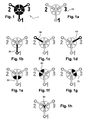
- Figure 1 shows all the segments composing the icon 1 as if all these segments were simultaneously activated, which, as will be seen later, is in fact never the case.
- Icon 1 occupies advantageously a minimum area of 7 mm square.
- Icon 1 comprises a first subset comprising three segments 20, 30, 40, each representative of an energy flow within one of the three inputs.
- the three segments of the first subset are arranged according to a first pattern which is substantially concentrically arranged with respect to the central point of said area.
- each of the three segments 20, 30, 40 includes a linear portion, and the linear portions of the segments are oriented at 120 degrees relative to each other so as to form a star centred on the central point of the area.
- Icon 1 also comprises a second subset of three segments 50, 60, 70, representative of the phase rotation.
- the segments of the second subset are arranged according to a second pattern, which is also substantially concentrically arranged with respect to the central point of the area.
- each segment 50, 60, 70 includes two ring portions, and are mutually arranged so that all the ring portions are distributed on a same circle centred on the central point of said area.
- linear portion of segment 20 separates the two ring portions of segment 50
- linear portion of segment 30 separates the two ring portions of segment 60
- linear portion of segment 40 separates the two ring portion of segment 70.
- Single icon 1 further comprises an additional segment 80, shown on figure 1h , for indicating the presence or absence of current flow in a neutral wire connected to the corresponding neutral input of the meter.
- the additional segment 80 is advantageously located at the central point of the area.
- Single icon 1 comprises at last a phase number indicating segment 10 forming a third pattern which is also advantageously concentrically arranged with respect to the central point of said area.
- This segment 10 is used for simultaneously displaying figures 1 , 2 and 3 in the vicinity of corresponding segments 20, 30, 40 of the first pattern.
- first, second and third patterns in one hand, and additional segment 80 and phase number indicating segment 10 on the other hand, are all concentrically arranged with respect to the central point of the area, which enables to obtain a global area of optimized size, typically of 7 mm square.
- Three segments 50, 60, 70 of the second subset are representative of the phase rotation. Due to the arrangement of these segments around the central point, successive displays of these segments act as a rotating indicator. More precisely, each of these segments 50, 60, 70 or some groups of segments are continuously successively activated/deactivated either in clockwise or in counter-clockwise rotation depending on the sign of the phase rotation. In addition, the rotation speed to which these segments or groups of segments are successively activated/deactivated depends on the instantaneous power level delivered through said meter.
- the three segments 50, 60, 70 of said second subset are successively activated/deactivated when instantaneous power level delivered through said meter corresponds to the lowest possible power level.
- Segments 50, 60, 70 are also used for indicating abnormal situations such as three meter inputs in phase, or two over three meter inputs in phase. To this end, all the segments 50, 60, 70 of the second subset are simultaneously activated in case the three inputs of the meter are in phase. Additionally, two segments of said second subset are simultaneously activated in case the corresponding inputs of the meter are in phase, while the remaining segment is flashing displayed.
- Array 1 Display meaning Segments lit / unlit / flashing Segments always lit Segment 10 Phase 1 Flow Monitoring Forward energy flow Segment 20 lit Reverse energy flow Segment 20 flashing No measurable energy flow Segment 20 unlit Phase 2 Flow Monitoring Forward energy flow Segment 30 lit Reverse energy flow Segment 30 flashing No measurable energy flow Segment 30 unlit Phase 3 Flow Monitoring Forward energy flow Segment 40 lit Reverse energy flow Segment 40 flashing No measurable energy flow Segment 40 unlit Phase rotation Normal phase rotation The following segments lit successively in sequence: - 50, 60, 70 continuously repeated to indicate rotation with lowest instantaneous power; or - 50+60, 60+70, 70+50 continuously repeated to indicate rotation with higher instantaneous power, - and the speed of rotation increased as instantaneous power increases Reverse phase rotation As above, but the segment illuminated in reverse sequence Abnormal situations All inputs in phase Segments 50, 60, 70 permanently lit Two inputs in phase, third input out of
- the three-phase meter is adapted not only for a three-phase, four-configuration (star or wye configuration), but also for a three-phase, three-wire configuration (delta configuration).
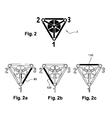
- Icon 2 shown on figure 2 comprises all the segments already disclosed for icon 1 with respect to figures 1 and 1a to 1h .
- First subset of segments used for representing energy flow however includes three additional segments 90, 100 and 110.
- each segment 90, 100, 110 include a linear portion, and the linear portions of the segments are advantageously mutually arranged so as to form a delta centred on the central point of said area.
- Star made of segments 20, 30, 40 lies within the delta made of segments 90, 100, 110.
- icon 2 is animated according to the rules summarized in above array 1.
- Array 2 Display meaning Segments lit / unlit / flashing Segments always lit Segment 10 Phase 1 Forward energy flow Segment 90 lit Flow Reverse energy flow Segment 90 flashing Monitoring No measurable energy flow Segment 90 unlit Phase 2 Forward energy flow Segment 100 lit Flow Reverse energy flow Segment 100 flashing Monitoring No measurable energy flow Segment 100 unlit Phase 3 Forward energy flow Segment 110 lit Flow Reverse energy flow Segment 110 flashing Monitoring No measurable energy flow Segment 110 unlit Phase rotation Normal phase rotation Normal phase rotation
- the second subset representative of the phase rotation comprises here not three, but six segments 50a, 50b, 60a, 60b, 70a, 70b, each including (see figures 3e to 3j ) one ring portion, said six segments being mutually arranged so that all the ring portions are distributed on a same circle centred on the central point of said area.
- two linear portions of corresponding two segments of said first subset surround two ring portions of corresponding two segments within said second subset.
- This third embodiment require more segments than the first embodiment (eleven segments against 8 segments in the first embodiment), but enables, within the same area of 7 mm square, to provide a smoother indication of rotation.
- the six segments 50a, 50b, 60a, 60b, 70a, 70b are advantageously successively activated/deactivated when instantaneous power level delivered through said meter corresponds to a lowest possible power level, while groups of two to five of successive segments among the six segments are successively activated/deactivated when instantaneous power level delivered through said meter increases.
- Array 3 Display meaning Segments lit / unlit / flashing Segments always lit Segment 10 Phase 1 forward energy flow Segment 20 lit Flow reverse energy flow Segment 20 flashing Monitoring no measurable energy flow Segment 20 unlit Phase 2 forward energy flow Segment 30 lit Flow reverse energy flow Segment 30 flashing Monitoring no measurable energy flow Segment 30 unlit Phase 3 forward energy flow Segment 40 lit Flow reverse energy flow Segment 40 flashing Monitoring no measurable energy flow Segment 40 unlit Phase rotation Normal phase rotation
- segments 20, 30 and 40 of the first subset shown on figures 4e to 4g correspond to segments already disclosed with respect to figures 1b to 1d
- neutral segment 80 shown on figure 4h correspond to segment disclosed with respect to figure 1h .
- the second subset representative of the phase rotation comprises three phase number indicating segments 10a, 10b, 10c (see figures 4a to 4c ), for independently displaying figures 1 , 2 and 3 in the vicinity of corresponding segments 20, 30, 40 of the first pattern.
- the figures are successively displayed in ascending or descending order depending on the sign of the phase rotation, and with a rotation speed depending on the instantaneous power level delivered through said meter.
- Array 4 Display meaning Segments lit / unlit flashing Segments always lit None Phase 1 forward energy flow Segment 20 lit Flow reverse energy flow Segment 20 flashing Monitoring no measurable energy flow Segment 20 unlit Phase 2 forward energy flow Segment 30 lit Flow reverse energy flow Segment 30 flashing Monitoring no measurable energy flow Segment 30 unlit Phase 3 forward energy flow Segment 40 lit Flow reverse energy flow Segment 40 flashing Monitoring no measurable energy flow Segment 40 unlit Phase rotation Normal phase rotation
- All inputs in phase All inputs in phase Segments 10a, 10b, 10c permanently lit Two inputs in phase, third input out of phase Two of the following segments permanently lit: 10a, 10b, 10c. The other, corresponding to the input out
- the three-phase meter is adapted not only for a three-phase, four-configuration (star or wye configuration), but also for a three-phase, three-wire configuration (delta configuration).
- Icon 4 shown on figure 5 comprises all the segments already disclosed for icon 3 with respect to figures 4 and 4a to 4h .
- First subset of segments used for representing energy flow however includes three additional segments 90, 100 and 110, shown separately on figures 5a to 5c .
- Each segment 90, 100, 110 include a linear portion, and the linear portions of the segments are advantageously mutually arranged so as to form a delta centred on the central point of said area.
- Star made of segments 20, 30, 40 ( figures 4e-4g ) lies within the delta made of segments 90, 100, 110.
- the three-phase meter is adapted not only for a three-phase, four-configuration (star or wye configuration), but also for a three-phase, three-wire configuration (delta configuration).
- Icon 5 shown on figure 6 comprises all the segments already disclosed for icon 4. Segment 110 does not comprise one but two linear portions (see figure 6c ), which enables figure 3 to be superimposed between these two linear portions, thus further optimizing the area size. Typically, an area of 5 mm square can be obtained.
- Array 5 summarizes the animation of icons 4 or 5 when the meter is used in the delta configuration: Array 5 Display meaning Segments lit / unlit flashing Segments always lit None Phase 1 forward energy flow Segment 90 lit Flow reverse energy flow Segment 90 flashing Monitoring no measurable energy flow Segment 90 unlit Phase 2 forward energy flow Segment 100 lit Flow reverse energy flow Segment 100 flashing Monitoring no measurable energy flow Segment 100 unlit Phase 3 forward energy flow Segment 110 lit Flow reverse energy flow Segment 110 flashing Monitoring no measurable energy flow Segment 110 unlit Phase rotation Normal phase rotation The following segments lit successively in sequence: - 10a, 10b, 10c continuously repeated to indicate rotation - and the speed of rotation increased as instantaneous power increases Reverse phase rotation As above, but the segment illuminated in reverse sequence Abnormal situations All inputs in phase Segments 10a, 10b, 10c permanently lit Two inputs in phase, third input out of phase Two of the following segments permanently lit: 10a, 10b, 10c. The other, corresponding to the input out of phase flashing Neutral
- Figure 7a illustrates a schematic of circuitry involved in a three-phase meter for animating the icon of figure 1
- figure 7b illustrates a schematic of circuitry for animating an icon adapted for a delta-connected three-phase meter:
- the invention clearly and effectively displays required phase and power information in a very small area of a meter display, including fault conditions.
- the invention is simple to implement on any segmented display.
- the invention allows for display sizes to be reduced, giving significant cost savings in an electricity meter design.
Landscapes
- Physics & Mathematics (AREA)
- General Physics & Mathematics (AREA)
- Measuring Phase Differences (AREA)
Description
- The present invention relates to three-phase electricity meters, and more especially to the display of information for monitoring the operating conditions of such meters.
- In a three-phase system, typically in electric power distribution grids, three circuit conductors carry three alternating currents of the same frequency which reach their instantaneous peak values at different times. Taking one conductor as the reference, the other two currents are delayed in time by one-third and two-thirds of one cycle of the electrical current. In addition, three-phase systems may or may not have a neutral wire.
- Electricity meters shall be designed for matching the electrical system configuration. Hence, some meters have been developed for three-phase, four-wire electricity supply (star or wye configuration), other meters have been developed for three-phase, three-wire electricity supply (delta configuration). Some other meters have even been developed for matching with both star and delta configurations.
- Whatever the configuration used for the three-phase meter, it is important to carefully monitor the operating conditions of the meter, and more precisely to acquire all relevant phase information to enable accurate diagnosis of wiring faults and supply conditions. Those relevant phase information are typically the following ones:
- For each input or phase, information about the energy flow (forward energy flow, reverse energy flow or no measurable energy flow);
- The phase rotation order of the inputs or phases;
- Indication that all the inputs or at least two inputs among the three phases are in phase with each other;
- Absence or presence of a neutral wire;
- The instantaneous power level being delivered through the meter.
- Some phase information is monitored and displayed in
JP 2002 168 883 DE 299 05 610 U1 andJP 2006 258 722 - On known electromechanical meters, the instantaneous power level is generally indicated by the speed of rotation of a disk.
- On known electronic meters, the instantaneous power is indicated by the rate at which an LED flashes on and off.
- Some known meters use a display with separate phase indicators for each input, each phase indicator being controlled to either light on, flash or light off depending on whether the energy flow through the phase is forward, reverse or null, and separate arrow indicators to show phase rotation, flashing to indicate an abnormal phase rotation, e.g. inputs in phase.
- Today, existing three-phase meters do not enable to monitor all the above-information, even for those meters provided with a display.
- This is mostly due to the fact that there is limited space on a meter display, due to physical and economical constraints. Also, segmented displays such as the types of liquid crystal display commonly used have a limited number of segments, to maximise the contrast ratio and ensure that the display is always readable.
- There is thus a need for a three-phase electricity meter that graphically displays the maximum of information relating to the phase conditions to allow an operator to see at first glance whether the operating conditions are correct or not, whilst minimising the amount of display area used and without introducing an excessive number of segments.
- To this end, the object of the invention is a three-phase electricity meter as defined in
claim 1, with at least three inputs adapted to connect to a three-phase electricity supply, said meter comprising a segment display that provides visual indications of information by selectively activating/deactivating a plurality of segments on said display and activation/deactivation means for selectively activating/deactivating said plurality of segments, characterized in that said plurality of segments are locally arranged in a same area of the display so as to form a single icon for monitoring the phase operating conditions of the meter, said single icon comprising at least : - A first subset of segments each representative of an energy flow within one of the three inputs, said segments of said first subset being arranged according to a first pattern;
- A second subset of segments representative of the phase rotation, said segments of said second subset being arranged according to a second pattern; wherein said first and second patterns are substantially concentrically arranged with respect to a central point of said area, and in that said activation/deactivation means are adapted to control:
- The switching of each segment of said first subset between three distinct optical states depending whether the energy flow of the corresponding input is a forward energy flow, a reverse energy flow or is not measurable;
- The successive activation/deactivation of each segment or group of segments of the second subset in clockwise or counter-clockwise rotation depending on the sign of the phase rotation, and with a rotation speed depending on the instantaneous power level delivered through said meter.
- In one embodiment, the first subset of segments comprises three segments, each including a linear portion, the linear portions of the segments being oriented at 120 degrees relative to each other so as to form a star centred on the central point of said area.
- Alternatively or in combination, the first subset of segments may also comprise three segments, each including a linear portion, the linear portions of the segments being mutually arranged so as to form a delta centred on the central point of said area.
- For three-phase meter further comprising a neutral input adapted to receive a neutral wire of the three-phase electricity supply, the single icon further comprises advantageously an additional segment for indicating the presence or absence of current flow in said neutral wire, preferably arranged on the central point of said area.
- According to another feature, the second subset may comprise three segments, each including two ring portions, said three segments being mutually arranged so that all the ring portions are distributed on a same circle centred on the central point of said area. In this case, two ring portions of a same segment within the second subset are preferably separated by a linear portion of one segment of the first subset.
- The three segments of the second subset are preferably successively activated/deactivated when instantaneous power level delivered through said meter corresponds to a lowest possible power level, while pairs of successive segments among the three segments are successively activated/deactivated when instantaneous power level delivered through said meter corresponds to a highest possible power level.
- Alternatively, the second subset may comprise six segments, each including one ring portion, said six segments being mutually arranged so that all the ring portions are distributed on a same circle centred on the central point of said area. In this case, the six segments are preferably successively activated/deactivated when instantaneous power level delivered through said meter corresponds to a lowest possible power level, while groups of two to five of successive segments among said six segments are successively activated/deactivated when instantaneous power level delivered through said meter increases.
- In another embodiment, single icon may further comprise a phase number indicating segment forming a third pattern substantially concentrically arranged with respect to the central point of said area, for simultaneously displaying
figures 1 ,2 and3 in the vicinity of corresponding segments of the first pattern. - In another embodiment, second subset comprises three phase number indicating segments, for independently displaying
figures 1 ,2 and3 in the vicinity of corresponding segments of the first pattern, and the activation/deactivation means are adapted to control continuously the successive display of the figures in ascending or descending order depending on the sign of the phase rotation, and with a rotation speed depending on the instantaneous power level delivered through said meter. - According to another feature, all the segments of the second subset are simultaneously activated in case the three inputs of the meter are all in phase. In addition, two segments of the second subset may be simultaneously activated in case the corresponding inputs of the meter are in phase, while the remaining segment is flashing displayed.
- Additional features of the invention will become apparent by reading the following detailed description of several possible embodiments, made in a connection with the following accompanying drawings:
-
Figure 1 shows a first example of an arrangement of segments forming a single icon for monitoring the phase operating conditions of the meter; -
Figures 1a to 1h show separately each segment involved in the constitution of the single icon offigure 1 ; -
Figure 2 shows a second example of an arrangement of segments forming a single icon for monitoring the phase operating conditions of the meter; -
Figures 2a to 2c show separately some of the segments involved in the constitution of the single icon offigure 2 ; -
Figure 3 shows a third example of an arrangement of segments forming a single icon for monitoring the phase operating conditions of the meter; -
Figures 3a to 3k show separately each segment involved in the constitution of the single icon offigure 3 ; -
Figure 4 shows a fourth example of an arrangement of segments forming a single icon for monitoring the phase operating conditions of the meter; -
Figures 4a to 4h show separately each segment involved in the constitution of the single icon offigure 4 ; -
Figure 5 shows a fifth example of an arrangement of segments forming a single icon for monitoring the phase operating conditions of the meter; -
Figures 5a to 5c show separately some of the segments involved in the constitution of the single icon offigure 5 ; -
Figure 6 shows a sixth example of an arrangement of segments forming a single icon for monitoring the phase operating conditions of the meter; -
Figures 6a to 6c show separately some of the segments involved in the constitution of the single icon offigure 6 ; -
Figures 7a and7b illustrate a schematic of circuitry involved in a three-phase meter for animating an icon, respectively for a star-connected meter and for a delta-connected meter. - With respect first to
figures 1 and 1a to 1h , a first embodiment of an animated iconic display enabling a complete and convivial monitoring of the phase operating conditions of a three-phase meter will now be described. We assume in the following discussion that the three-phase meter has three inputs adapted to connect the phases of a three-phase energy supply in a star configuration, and a neutral input adapted to connect the neutral wire of the energy supply. -
Figure 1 shows all the segments composing theicon 1 as if all these segments were simultaneously activated, which, as will be seen later, is in fact never the case.Icon 1 occupies advantageously a minimum area of 7 mm square. -
Icon 1 comprises a first subset comprising threesegments - As better shown in
figures 1b to 1d , each of the threesegments -
Icon 1 also comprises a second subset of threesegments - As better shown in
figures 1e to 1g , eachsegment - In this embodiment, two ring portions of a same segment within said second subset are separated by a linear portion of one segment of said first subset. Hence, linear portion of
segment 20 separates the two ring portions ofsegment 50, linear portion ofsegment 30 separates the two ring portions ofsegment 60, and linear portion ofsegment 40 separates the two ring portion ofsegment 70. -
Single icon 1 further comprises anadditional segment 80, shown onfigure 1h , for indicating the presence or absence of current flow in a neutral wire connected to the corresponding neutral input of the meter. Theadditional segment 80 is advantageously located at the central point of the area. -
Single icon 1 comprises at last a phasenumber indicating segment 10 forming a third pattern which is also advantageously concentrically arranged with respect to the central point of said area. Thissegment 10 is used for simultaneously displayingfigures 1 ,2 and3 in the vicinity of correspondingsegments - From the description above, it appears that first, second and third patterns in one hand, and
additional segment 80 and phasenumber indicating segment 10 on the other hand, are all concentrically arranged with respect to the central point of the area, which enables to obtain a global area of optimized size, typically of 7 mm square. - This arrangement, combined with the way the different segments are activated/deactivated for monitoring the phase operating conditions, enables an accurate diagnosis of wiring faults and supply conditions with a optimized number of segments (total of 8 segments), as will now be explained:
- As seen above,
segments - Three
segments segments - For instance, the three
segments - When instantaneous power level delivered through said meter corresponds to a highest possible power level, pairs of successive segments among the three
segments -
Segments segments - The way the different segments of
icon 1 may be controlled is summarized in the following Array 1:Array 1Display meaning Segments lit / unlit / flashing Segments always lit Segment 10Phase 1
Flow
MonitoringForward energy flow Segment 20 lit Reverse energy flow Segment 20 flashing No measurable energy flow Segment 20 unlit Phase 2
Flow
MonitoringForward energy flow Segment 30 lit Reverse energy flow Segment 30 flashing No measurable energy flow Segment 30 unlit Phase 3
Flow
MonitoringForward energy flow Segment 40 lit Reverse energy flow Segment 40 flashing No measurable energy flow Segment 40 unlit Phase rotation Normal phase rotation The following segments lit successively in sequence:
- 50, 60, 70 continuously repeated to indicate rotation with lowest instantaneous power; or
- 50+60, 60+70, 70+50 continuously repeated to indicate rotation with higher instantaneous power,
- and the speed of rotation increased as instantaneous power increasesReverse phase rotation As above, but the segment illuminated
in reverse sequenceAbnormal situations All inputs in phase Segments 50, 60, 70 permanently lit Two inputs in phase, third input out of phase Two of the following segments
permanently lit: 50, 60, 70. The other,
corresponding to the input out of phase
flashingNeutral monitoring Neutral present Segment 80 lit Neutral not present Segment 80 unlit - Turning now to
figures 2 and 2a to 2c , a second embodiment of an animated iconic display enabling a complete and convivial monitoring of the phase operating conditions of a three-phase meter will now be described. Here, the three-phase meter is adapted not only for a three-phase, four-configuration (star or wye configuration), but also for a three-phase, three-wire configuration (delta configuration). -
Icon 2 shown onfigure 2 comprises all the segments already disclosed foricon 1 with respect tofigures 1 and 1a to 1h . - First subset of segments used for representing energy flow however includes three
additional segments - As shown on
figures 2a to 2c , eachsegment - Star made of
segments figures 1b-1d ) lies within the delta made ofsegments - When the three-phase meter is used in the star configuration,
icon 2 is animated according to the rules summarized inabove array 1. - If however, the meter is used in the delta configuration,
icon 2 is animated as summarized in following Array 2:Array 2Display meaning Segments lit / unlit / flashing Segments always lit Segment 10Phase 1Forward energy flow Segment 90 lit Flow Reverse energy flow Segment 90 flashing Monitoring No measurable energy flow Segment 90 unlit Phase 2 Forward energy flow Segment 100 lit Flow Reverse energy flow Segment 100 flashing Monitoring No measurable energy flow Segment 100 unlit Phase 3 Forward energy flow Segment 110 lit Flow Reverse energy flow Segment 110 flashing Monitoring No measurable energy flow Segment 110 unlit Phase rotation Normal phase rotation Normal phase rotation The following segments lit successively in sequence:
- 50, 60, 70 continuously repeated to indicate rotation with lowest instantaneous power; or
- 50+60, 60+70, 70+50 continuously repeated to indicate rotation with higher instantaneous power,
- and the speed of rotation increased as instantaneous power increasesReverse phase rotation As above, but the segment illuminated in reverse sequence Abnormal situations All inputs in phase Segments 50, 60, 70 permanently lit Two inputs in phase, third input out of phase Two of the following segments
permanently lit: 50, 60, 70. The other,
corresponding to the input out of phase
flashing - Here again, an operator can monitor at first glance the configuration of use of the meter, thanks to the use of shapes (delta and star) which correspond to the standard symbols of the wye or delta configuration, and the phase conditions.
- Turning now to
figures 3a to 3k , a third embodiment of an animated iconic display enabling a complete and convivial monitoring of the phase operating conditions of a three-phase meter adapted for star configuration will now be described: - Here, the icon has the same constitution than
icon 1 of the first embodiment, except concerning the composition of the second subset representative of the phase rotation. Hence,segments figures 3b to 3d correspond to segments already disclosed with respect tofigures 1b to 1d ,neutral segment 80 shown onfigure 3k correspond to segment disclosed with respect tofigure 1h , and phasenumber indicating segment 10 shown onfigure 3a corresponds to segment disclosed with respect tofigure 1a . - In a different manner however, the second subset representative of the phase rotation comprises here not three, but six
segments figures 3e to 3j ) one ring portion, said six segments being mutually arranged so that all the ring portions are distributed on a same circle centred on the central point of said area. - Here again, two linear portions of corresponding two segments of said first subset surround two ring portions of corresponding two segments within said second subset.
- This third embodiment require more segments than the first embodiment (eleven segments against 8 segments in the first embodiment), but enables, within the same area of 7 mm square, to provide a smoother indication of rotation.
- Indeed, in this embodiment, the six
segments - The way the different segments of icon according to this third embodiment may be controlled is summarized in the following Array 3:
Array 3Display meaning Segments lit / unlit / flashing Segments always lit Segment 10Phase 1forward energy flow Segment 20 lit Flow reverse energy flow Segment 20 flashing Monitoring no measurable energy flow Segment 20 unlit Phase 2 forward energy flow Segment 30 lit Flow reverse energy flow Segment 30 flashing Monitoring no measurable energy flow Segment 30 unlit Phase 3 forward energy flow Segment 40 lit Flow reverse energy flow Segment 40 flashing Monitoring no measurable energy flow Segment 40 unlit Phase rotation Normal phase rotation The following segments lit in sequence:
- 50a, 50b, 60a, 60b, 70a, 70b to indicate rotation with lowest instantaneous power; or
- to indicate the next level adding another segment in the group each time as power increased up to an
intermediate level where segments are rotated in groups of five
(50a+50b+60a+60b+70a,
50b+ 60a+60b+70a+70b,
60a+60b+70a+70b+50a,
60b+ 70a+70b+50a+50b,
70a+70b+50a+50b+60a,
70b+ 50a+50b+60a+60b), then the
speed of rotation increased as
instantaneous power increasesReverse phase rotation As above, but the segment illuminated
in reverse sequenceAbnormal situations All inputs in phase in phase Segments 50a, 50b, 60a, 60b, 70a,
70b, 80a, 80b permanently litTwo inputs in phase, third input out of phase input out of phase Two of the following segments pairs
permanently lit: (50a, 50b), (60a,
60b), (70a, 70b). The other,
corresponding to the input out of phase
flashingNeutral Neutral present Segment 80 lit monitoring Neutral not present Segment 80 unlit - Three other embodiments which enable to further optimize the total area of the icon will now be described.
- Turning now to
figures 4, and 4a to 4k , a fourth embodiment of an animated iconic display enabling a complete and convivial monitoring of the phase operating conditions of a three-phase meter adapted for star configuration will now be described: - Here,
icon 3 shown infigure 4 has the same constitution thanicon 1 of the first embodiment, as far as the first subset of segments used for monitoring flow energy, and the neutral indicator are concerned. - Hence,
segments figures 4e to 4g correspond to segments already disclosed with respect tofigures 1b to 1d ,neutral segment 80 shown onfigure 4h correspond to segment disclosed with respect tofigure 1h . - In a different manner however, the second subset representative of the phase rotation comprises three phase
number indicating segments figures 4a to 4c ), for independently displayingfigures 1 ,2 and3 in the vicinity of correspondingsegments - In this embodiment, the figures are successively displayed in ascending or descending order depending on the sign of the phase rotation, and with a rotation speed depending on the instantaneous power level delivered through said meter.
- The way the different segments of icon according to this fourth embodiment may be controlled is summarized in the following Array 4:
Array 4Display meaning Segments lit / unlit flashing Segments always lit None Phase 1 forward energy flow Segment 20 lit Flow reverse energy flow Segment 20 flashing Monitoring no measurable energy flow Segment 20 unlit Phase 2 forward energy flow Segment 30 lit Flow reverse energy flow Segment 30 flashing Monitoring no measurable energy flow Segment 30 unlit Phase 3 forward energy flow Segment 40 lit Flow reverse energy flow Segment 40 flashing Monitoring no measurable energy flow Segment 40 unlit Phase rotation Normal phase rotation The following segments lit successively in sequence:
- 10a, 10b, 10c continuously repeated to indicate rotation
- and the speed of rotation increased as instantaneous power increasesReverse phase rotation As above, but the segment illuminated
in reverse sequenceAbnormal situations All inputs in phase All inputs in phase Segments 10a, 10b, 10c permanently lit Two inputs in phase, third
input out of phaseTwo of the following segments
permanently lit: 10a, 10b, 10c. The
other, corresponding to the input out
of phase flashingNeutral Neutral present Segment 80 lit monitoring Neutral not present Segment 80 unlit - Turning now to
figures 5 and 5a to 5c , a fifth embodiment of an animated iconic display enabling a complete and convivial monitoring of the phase operating conditions of a three-phase meter will now be described. Here, the three-phase meter is adapted not only for a three-phase, four-configuration (star or wye configuration), but also for a three-phase, three-wire configuration (delta configuration). -
Icon 4 shown onfigure 5 comprises all the segments already disclosed foricon 3 with respect tofigures 4 and 4a to 4h . - First subset of segments used for representing energy flow however includes three
additional segments figures 5a to 5c . Eachsegment segments figures 4e-4g ) lies within the delta made ofsegments - Turning now to
figures 6 and 6a to 6c , a sixth embodiment of an animated iconic display enabling a complete and convivial monitoring of the phase operating conditions of a three-phase meter will now be described. - Here again, the three-phase meter is adapted not only for a three-phase, four-configuration (star or wye configuration), but also for a three-phase, three-wire configuration (delta configuration).
-
Icon 5 shown onfigure 6 comprises all the segments already disclosed foricon 4.Segment 110 does not comprise one but two linear portions (seefigure 6c ), which enablesfigure 3 to be superimposed between these two linear portions, thus further optimizing the area size. Typically, an area of 5 mm square can be obtained. - Following
Array 5 summarizes the animation oficons Array 5Display meaning Segments lit / unlit flashing Segments always lit None Phase 1 forward energy flow Segment 90 lit Flow reverse energy flow Segment 90 flashing Monitoring no measurable energy flow Segment 90 unlit Phase 2 forward energy flow Segment 100 lit Flow reverse energy flow Segment 100 flashing Monitoring no measurable energy flow Segment 100 unlit Phase 3 forward energy flow Segment 110 lit Flow reverse energy flow Segment 110 flashing Monitoring no measurable energy flow Segment 110 unlit Phase rotation Normal phase rotation The following segments lit successively in sequence:
- 10a, 10b, 10c continuously repeated to indicate rotation
- and the speed of rotation increased as instantaneous power increasesReverse phase rotation As above, but the segment illuminated
in reverse sequenceAbnormal situations All inputs in phase Segments 10a, 10b, 10c permanently lit Two inputs in phase, third input out of phase Two of the following segments
permanently lit: 10a, 10b, 10c. The
other, corresponding to the input out
of phase flashingNeutral Neutral present Segment 80 lit monitoring Neutral not present Segment 80 unlit -
Figure 7a illustrates a schematic of circuitry involved in a three-phase meter for animating the icon offigure 1 , whilefigure 7b illustrates a schematic of circuitry for animating an icon adapted for a delta-connected three-phase meter: - In both
figures 7a and7b , the three-phase meter comprises current andvoltage sensors metrology microprocessor 230 of the meter. In the case offigure 7a , for which the meter has also a neutral input, the circuitry comprises connection means 240 for enabling the detection of the presence or absence of current flow in the neutral. Current and voltage measurements are used bymicroprocessor 230 for calculating the energy which is delivered to the consumer equipment, and storing the result in data storage means 250.Microcontroller 230 also controls aLCD display 260 for displaying icon used for monitoring the phase operating conditions of the meter. As shown in dotted lines, voltage and current measurements are used for controlling the first subset of segments (star or delta arrangement), while a power manager andphase rotation module 231 of themicroprocessor 230 controls the second subset of segment according to the rules summarized in Array 1 (forfigure 7a ) or Array 2 (forfigure 7b ). In the case offigure 7a ,microprocessor 230 also includes aneutral detection module 232 receiving the output of connectingmeans 240, and controlling central segment of the icon accordingly. - The invention clearly and effectively displays required phase and power information in a very small area of a meter display, including fault conditions.
- The invention is simple to implement on any segmented display.
- The invention allows for display sizes to be reduced, giving significant cost savings in an electricity meter design.
Claims (18)
- A three-phase electricity meter with at least three inputs adapted to connect to a three-phase electricity supply, said meter comprising a segment display (260) that provides visual indications of information by selectively activating/deactivating a plurality of segments on said display and activation/deactivation means (200-230) for selectively activating/deactivating said plurality of segments, wherein said plurality of segments are locally arranged in a same area of the display so as to form a single icon (1;2;3;4;5) for monitoring the phase operating conditions of the meter, said single icon (1;2;3;4;5) comprising at least :- A first subset of segments (20, 30, 40, 90, 100, 110) each representative of an energy flow within one of the three inputs, said segments of said first subset being arranged according to a first pattern;- A second subset of segments (50, 60, 70; 50a, 50b, 60a, 60b, 70a, 70b; 10a, 10b, 10c) representative of the phase rotation, said segments of said second subset being arranged according to a second pattern;wherein said first and second patterns are substantially concentrically arranged with respect to a central point of said area, and in that said activation/deactivation means (200-230) control :- The switching of each segment (20, 30, 40, 90, 100, 110) of said first subset between three distinct optical states depending whether the energy flow of the corresponding input is a forward energy flow, a reverse energy flow or is not measurable;- The successive activation/deactivation of each segment (50, 60, 70; 10a, 10b, 10c) or group of segments (50a, 50b, 60a, 60b, 70a, 70b) of the second subset in clockwise or counter-clockwise rotation depending on the sign of the phase rotation, and with a rotation speed depending on the instantaneous power level delivered through said meter.
- A three-Phase electricity meter according to claim 1, characterized in that said first subset of segments comprises three segments (20, 30, 40), each including a linear portion, the linear portions of the segments being oriented at 120 degrees relative to each other so as to form a star centred on the central point of said area.
- A three-phase electricity meter according to anyone of the preceding claim, characterized in that said first subset of segments comprises three segments (90, 100, 110), each including a linear portion, the linear portions of the segments being mutually arranged so as to form a delta centred on the central point of said area.
- A three-phase electricity meter according to anyone of the preceding claims, further comprising a neutral input adapted to receive a neutral wire of said three-phase electricity supply, characterized in that said single icon further comprises an additional segment (80) for indicating the presence or absence of current flow in said neutral wire.
- A three-phase electricity meter according to claim 4, characterized in that said additional segment (80) is arranged on the central point of said area.
- A three-phase electricity meter according to anyone of the preceding claims, characterized in that said distinct optical states for the switching of segments of said first subset correspond to the display on, the display off and the flashing display.
- A three-phase electricity meter according to anyone of the preceding claims, characterized in that said second subset comprises three segments (50, 60, 70), each including two ring portions, said three segments being mutually arranged so that all the ring portions are distributed on a same circle centred on the central point of said area.
- A three-phase electricity meter according to a combination of claims 2 and 7, characterized in that two ring portions of a same segment within said second subset are separated by a linear portion of one segment of said first subset.
- A three-phase electricity meter according to anyone of claims 7 or 8, characterized in that the three segments (50, 60, 70) of said second subset are successively activated/deactivated when instantaneous power level delivered through said meter corresponds to a lowest possible power level, while pairs (50-60, 60-70, 70-50) of successive segments among the three segments (50, 60, 70) are successively activated/deactivated when instantaneous power level delivered through said meter corresponds to a highest possible power level.
- A three-phase electricity meter according to anyone of claims 1 to 7, characterized in that said second subset comprises six segments (50a, 50b, 60a, 60b, 70a, 70b), each including one ring portion, said six segments being mutually arranged so that all the ring portions are distributed on a same circle centred on the central point of said area.
- A three-phase electricity meter according to a combination of claims 2 and 10, characterized in that two linear portions of corresponding two segments of said first subset surround two ring portions of corresponding two segments within said second subset.
- A three-phase electricity meter according to anyone of claims 10 or 11, characterized in that the six segments (50a, 50b, 60a, 60b, 70a, 70b) are successively activated/deactivated when instantaneous power level delivered through said meter corresponds to a lowest possible power level, while groups of two to five of successive segments among said six segments (50, 60, 70) are successively activated/deactivated when instantaneous power level delivered through said meter increases.
- A three-phase electricity meter according to anyone of claims 1 to 12, characterized in that said single icon (1; 2; 3) further comprises a phase number indicating segment (10) forming a third pattern substantially concentrically arranged with respect to the central point of said area, for simultaneously displaying figures 1, 2 and 3 in the vicinity of corresponding segments of the first pattern.
- A three-phase meter according to claim 13, characterized in that said first, second and third patterns are arranged within an area of 7 mm square.
- A three-phase, electricity meter according to anyone of claims 1 to 6, characterized in that said second subset comprises three phase number indicating segments (10a, 10b, 10c), for independently displaying figures 1, 2 and 3 in the vicinity of corresponding segments of the first pattern, and in that said activation/deactivation means (200-230) are adapted to control continuously the successive display of the figures in ascending or descending order depending on the sign of the phase rotation, and with a rotation speed depending on the instantaneous power level delivered through said meter.
- A three-phase electricity meter according to claim 15, characterized in that said first and second patterns are arranged within an area of 5 mm square.
- A three-phase electricity meter according to anyone of the preceding claims, characterized in that all the segments (50, 60, 70; 50a, 50b, 60a, 60b, 70a, 70b; 10a, 10b, 10c) of said second subset are simultaneously activated in case the three inputs of the meter are all in phase.
- A three-phase electricity meter according to anyone of the preceding claims, characterized in that two segments (50, 60, 70; 50a, 50b, 60a, 60b, 70a, 70b; 10a, 10b, 10c) of said second subset are simultaneously activated in case the corresponding inputs of the meter are in phase, while the remaining segment is flashing displayed.
Priority Applications (1)
| Application Number | Priority Date | Filing Date | Title |
|---|---|---|---|
| EP20090176690 EP2325663B1 (en) | 2009-11-20 | 2009-11-20 | Three-phase electricity meter with phase monitoring indicator |
Applications Claiming Priority (1)
| Application Number | Priority Date | Filing Date | Title |
|---|---|---|---|
| EP20090176690 EP2325663B1 (en) | 2009-11-20 | 2009-11-20 | Three-phase electricity meter with phase monitoring indicator |
Publications (2)
| Publication Number | Publication Date |
|---|---|
| EP2325663A1 EP2325663A1 (en) | 2011-05-25 |
| EP2325663B1 true EP2325663B1 (en) | 2013-01-02 |
Family
ID=42077304
Family Applications (1)
| Application Number | Title | Priority Date | Filing Date |
|---|---|---|---|
| EP20090176690 Active EP2325663B1 (en) | 2009-11-20 | 2009-11-20 | Three-phase electricity meter with phase monitoring indicator |
Country Status (1)
| Country | Link |
|---|---|
| EP (1) | EP2325663B1 (en) |
Families Citing this family (4)
| Publication number | Priority date | Publication date | Assignee | Title |
|---|---|---|---|---|
| CN106018984B (en) * | 2016-05-14 | 2019-01-11 | 广东朗腾电气有限公司 | A kind of three-phase transformer group test method |
| CN107329105B (en) * | 2017-06-26 | 2019-12-10 | 云南电网有限责任公司西双版纳供电局 | Three-phase four-wire multifunctional electric energy meter wiring judgment method |
| CN107884734B (en) * | 2017-10-24 | 2023-04-28 | 广东电网有限责任公司茂名供电局 | Phase sequence table testing arrangement |
| CN109839547B (en) * | 2017-11-24 | 2024-01-30 | 深圳市蓝海华腾技术股份有限公司 | Three-phase power phase sequence detection circuit |
Family Cites Families (11)
| Publication number | Priority date | Publication date | Assignee | Title |
|---|---|---|---|---|
| GB1483191A (en) * | 1974-08-23 | 1977-08-17 | Sangamo Weston | Electricity meters |
| EP0446962A3 (en) * | 1986-04-11 | 1992-06-03 | Schlumberger Industries, Inc. | Solid state electricity meter display |
| US5039936A (en) * | 1989-12-13 | 1991-08-13 | Houston Industries Incorporated | Voltage rotation indicator mounting apparatus |
| JP3675559B2 (en) * | 1996-01-31 | 2005-07-27 | 東北電力株式会社 | Vector display method of measurement data |
| DE19713282C1 (en) * | 1997-03-29 | 1998-08-20 | Ralf Knobloch | Single pole phase test unit determining rotation and phase of three-phase AC mains |
| DE29905610U1 (en) * | 1999-03-30 | 1999-07-15 | Gossen-Metrawatt GmbH, 90471 Nürnberg | Electronic measuring and / or display device for measuring the direction of rotation of an electrical three-phase voltage system |
| JP4702726B2 (en) * | 2000-11-30 | 2011-06-15 | 日置電機株式会社 | Display method of vector lines in power meter |
| US7265532B2 (en) * | 2004-06-02 | 2007-09-04 | General Electric Company | Electronic electricity meter and method of assembly |
| JP2006258722A (en) * | 2005-03-18 | 2006-09-28 | Chudenko Corp | Voltage / phase rotation checker and detector clip |
| CN2809656Y (en) * | 2005-07-21 | 2006-08-23 | 林建军 | Detection device for phase sequence of three-phase AC power supply |
| CN201138359Y (en) * | 2007-12-27 | 2008-10-22 | 栾浩东 | Non-contact type phase sequence detector circuit |
-
2009
- 2009-11-20 EP EP20090176690 patent/EP2325663B1/en active Active
Also Published As
| Publication number | Publication date |
|---|---|
| EP2325663A1 (en) | 2011-05-25 |
Similar Documents
| Publication | Publication Date | Title |
|---|---|---|
| US6703823B1 (en) | Method and apparatus for electronic meter testing | |
| EP3367111B1 (en) | Energy metering system | |
| EP2325663A1 (en) | Three-phase electricity meters with phase monitoring indicator | |
| US20090262138A1 (en) | Enhanced power distribution unit with self-orienting display | |
| AU2010100428A4 (en) | Method and Apparatus for Power Supply Fault Detection | |
| US4247852A (en) | Monitoring system for indicators utilizing individually energizable segments | |
| US20170242059A1 (en) | Indicators for a power meter | |
| US4086568A (en) | Modular I/O equipment for controlling field devices directly or as an interface | |
| KR101041398B1 (en) | Switchgear current monitoring device | |
| CN108132368A (en) | A kind of purely resistive load system | |
| KR20170066107A (en) | Sub metering distributed board based on hall sensor and dsp calculating architecture | |
| JP6732603B2 (en) | Bus monitor | |
| CA2716587C (en) | Faulted circuit indicator with fault characteristic detection and display | |
| JP4444574B2 (en) | Method, computer program and device for validity check of current transformer in switchgear, and switchgear having the device | |
| US20010013771A1 (en) | Phase failure monitoring | |
| JPH0298675A (en) | Phase checker | |
| JP5827047B2 (en) | Power consumption status display device | |
| US5623201A (en) | 3-phase power meter having a display board | |
| CN105910832A (en) | Gear function detection device of gear shifter | |
| JPH07270459A (en) | Multi-circuit type power management meter for high voltage receiving and transforming equipment | |
| KR101614255B1 (en) | Monitoring device of current flow with multiple feeder and switch board equipped with the same | |
| JP2011122907A (en) | Electronic indicating instrument | |
| JP3156901U (en) | scale | |
| US8305223B2 (en) | Multi-object protection, control, and monitoring in the same intelligent electronic device | |
| EP0091667A1 (en) | Indicator panel for a central rephasing unit, particularly for industrial plants |
Legal Events
| Date | Code | Title | Description |
|---|---|---|---|
| PUAI | Public reference made under article 153(3) epc to a published international application that has entered the european phase |
Free format text: ORIGINAL CODE: 0009012 |
|
| AK | Designated contracting states |
Kind code of ref document: A1 Designated state(s): AT BE BG CH CY CZ DE DK EE ES FI FR GB GR HR HU IE IS IT LI LT LU LV MC MK MT NL NO PL PT RO SE SI SK SM TR |
|
| AX | Request for extension of the european patent |
Extension state: AL BA RS |
|
| 17P | Request for examination filed |
Effective date: 20111125 |
|
| GRAP | Despatch of communication of intention to grant a patent |
Free format text: ORIGINAL CODE: EPIDOSNIGR1 |
|
| GRAS | Grant fee paid |
Free format text: ORIGINAL CODE: EPIDOSNIGR3 |
|
| GRAA | (expected) grant |
Free format text: ORIGINAL CODE: 0009210 |
|
| AK | Designated contracting states |
Kind code of ref document: B1 Designated state(s): AT BE BG CH CY CZ DE DK EE ES FI FR GB GR HR HU IE IS IT LI LT LU LV MC MK MT NL NO PL PT RO SE SI SK SM TR |
|
| REG | Reference to a national code |
Ref country code: GB Ref legal event code: FG4D |
|
| REG | Reference to a national code |
Ref country code: AT Ref legal event code: REF Ref document number: 591887 Country of ref document: AT Kind code of ref document: T Effective date: 20130115 Ref country code: CH Ref legal event code: EP |
|
| REG | Reference to a national code |
Ref country code: IE Ref legal event code: FG4D |
|
| REG | Reference to a national code |
Ref country code: DE Ref legal event code: R096 Ref document number: 602009012406 Country of ref document: DE Effective date: 20130228 |
|
| REG | Reference to a national code |
Ref country code: AT Ref legal event code: MK05 Ref document number: 591887 Country of ref document: AT Kind code of ref document: T Effective date: 20130102 |
|
| REG | Reference to a national code |
Ref country code: NL Ref legal event code: VDEP Effective date: 20130102 |
|
| PG25 | Lapsed in a contracting state [announced via postgrant information from national office to epo] |
Ref country code: SI Free format text: LAPSE BECAUSE OF FAILURE TO SUBMIT A TRANSLATION OF THE DESCRIPTION OR TO PAY THE FEE WITHIN THE PRESCRIBED TIME-LIMIT Effective date: 20130102 |
|
| REG | Reference to a national code |
Ref country code: LT Ref legal event code: MG4D |
|
| PG25 | Lapsed in a contracting state [announced via postgrant information from national office to epo] |
Ref country code: BE Free format text: LAPSE BECAUSE OF FAILURE TO SUBMIT A TRANSLATION OF THE DESCRIPTION OR TO PAY THE FEE WITHIN THE PRESCRIBED TIME-LIMIT Effective date: 20130102 Ref country code: SE Free format text: LAPSE BECAUSE OF FAILURE TO SUBMIT A TRANSLATION OF THE DESCRIPTION OR TO PAY THE FEE WITHIN THE PRESCRIBED TIME-LIMIT Effective date: 20130102 Ref country code: NO Free format text: LAPSE BECAUSE OF FAILURE TO SUBMIT A TRANSLATION OF THE DESCRIPTION OR TO PAY THE FEE WITHIN THE PRESCRIBED TIME-LIMIT Effective date: 20130402 Ref country code: IS Free format text: LAPSE BECAUSE OF FAILURE TO SUBMIT A TRANSLATION OF THE DESCRIPTION OR TO PAY THE FEE WITHIN THE PRESCRIBED TIME-LIMIT Effective date: 20130502 Ref country code: CZ Free format text: LAPSE BECAUSE OF FAILURE TO SUBMIT A TRANSLATION OF THE DESCRIPTION OR TO PAY THE FEE WITHIN THE PRESCRIBED TIME-LIMIT Effective date: 20130102 Ref country code: LT Free format text: LAPSE BECAUSE OF FAILURE TO SUBMIT A TRANSLATION OF THE DESCRIPTION OR TO PAY THE FEE WITHIN THE PRESCRIBED TIME-LIMIT Effective date: 20130102 Ref country code: AT Free format text: LAPSE BECAUSE OF FAILURE TO SUBMIT A TRANSLATION OF THE DESCRIPTION OR TO PAY THE FEE WITHIN THE PRESCRIBED TIME-LIMIT Effective date: 20130102 Ref country code: BG Free format text: LAPSE BECAUSE OF FAILURE TO SUBMIT A TRANSLATION OF THE DESCRIPTION OR TO PAY THE FEE WITHIN THE PRESCRIBED TIME-LIMIT Effective date: 20130402 Ref country code: ES Free format text: LAPSE BECAUSE OF FAILURE TO SUBMIT A TRANSLATION OF THE DESCRIPTION OR TO PAY THE FEE WITHIN THE PRESCRIBED TIME-LIMIT Effective date: 20130413 |
|
| PG25 | Lapsed in a contracting state [announced via postgrant information from national office to epo] |
Ref country code: PL Free format text: LAPSE BECAUSE OF FAILURE TO SUBMIT A TRANSLATION OF THE DESCRIPTION OR TO PAY THE FEE WITHIN THE PRESCRIBED TIME-LIMIT Effective date: 20130102 Ref country code: NL Free format text: LAPSE BECAUSE OF FAILURE TO SUBMIT A TRANSLATION OF THE DESCRIPTION OR TO PAY THE FEE WITHIN THE PRESCRIBED TIME-LIMIT Effective date: 20130102 Ref country code: LV Free format text: LAPSE BECAUSE OF FAILURE TO SUBMIT A TRANSLATION OF THE DESCRIPTION OR TO PAY THE FEE WITHIN THE PRESCRIBED TIME-LIMIT Effective date: 20130102 Ref country code: GR Free format text: LAPSE BECAUSE OF FAILURE TO SUBMIT A TRANSLATION OF THE DESCRIPTION OR TO PAY THE FEE WITHIN THE PRESCRIBED TIME-LIMIT Effective date: 20130403 Ref country code: PT Free format text: LAPSE BECAUSE OF FAILURE TO SUBMIT A TRANSLATION OF THE DESCRIPTION OR TO PAY THE FEE WITHIN THE PRESCRIBED TIME-LIMIT Effective date: 20130502 Ref country code: FI Free format text: LAPSE BECAUSE OF FAILURE TO SUBMIT A TRANSLATION OF THE DESCRIPTION OR TO PAY THE FEE WITHIN THE PRESCRIBED TIME-LIMIT Effective date: 20130102 |
|
| PG25 | Lapsed in a contracting state [announced via postgrant information from national office to epo] |
Ref country code: HR Free format text: LAPSE BECAUSE OF FAILURE TO SUBMIT A TRANSLATION OF THE DESCRIPTION OR TO PAY THE FEE WITHIN THE PRESCRIBED TIME-LIMIT Effective date: 20130102 |
|
| PG25 | Lapsed in a contracting state [announced via postgrant information from national office to epo] |
Ref country code: DK Free format text: LAPSE BECAUSE OF FAILURE TO SUBMIT A TRANSLATION OF THE DESCRIPTION OR TO PAY THE FEE WITHIN THE PRESCRIBED TIME-LIMIT Effective date: 20130102 Ref country code: EE Free format text: LAPSE BECAUSE OF FAILURE TO SUBMIT A TRANSLATION OF THE DESCRIPTION OR TO PAY THE FEE WITHIN THE PRESCRIBED TIME-LIMIT Effective date: 20130102 Ref country code: RO Free format text: LAPSE BECAUSE OF FAILURE TO SUBMIT A TRANSLATION OF THE DESCRIPTION OR TO PAY THE FEE WITHIN THE PRESCRIBED TIME-LIMIT Effective date: 20130102 Ref country code: SK Free format text: LAPSE BECAUSE OF FAILURE TO SUBMIT A TRANSLATION OF THE DESCRIPTION OR TO PAY THE FEE WITHIN THE PRESCRIBED TIME-LIMIT Effective date: 20130102 |
|
| PLBE | No opposition filed within time limit |
Free format text: ORIGINAL CODE: 0009261 |
|
| STAA | Information on the status of an ep patent application or granted ep patent |
Free format text: STATUS: NO OPPOSITION FILED WITHIN TIME LIMIT |
|
| PG25 | Lapsed in a contracting state [announced via postgrant information from national office to epo] |
Ref country code: CY Free format text: LAPSE BECAUSE OF FAILURE TO SUBMIT A TRANSLATION OF THE DESCRIPTION OR TO PAY THE FEE WITHIN THE PRESCRIBED TIME-LIMIT Effective date: 20130102 |
|
| 26N | No opposition filed |
Effective date: 20131003 |
|
| REG | Reference to a national code |
Ref country code: DE Ref legal event code: R097 Ref document number: 602009012406 Country of ref document: DE Effective date: 20131003 |
|
| REG | Reference to a national code |
Ref country code: CH Ref legal event code: PL |
|
| PG25 | Lapsed in a contracting state [announced via postgrant information from national office to epo] |
Ref country code: CH Free format text: LAPSE BECAUSE OF NON-PAYMENT OF DUE FEES Effective date: 20131130 Ref country code: MC Free format text: LAPSE BECAUSE OF FAILURE TO SUBMIT A TRANSLATION OF THE DESCRIPTION OR TO PAY THE FEE WITHIN THE PRESCRIBED TIME-LIMIT Effective date: 20130102 Ref country code: LI Free format text: LAPSE BECAUSE OF NON-PAYMENT OF DUE FEES Effective date: 20131130 |
|
| REG | Reference to a national code |
Ref country code: IE Ref legal event code: MM4A |
|
| PG25 | Lapsed in a contracting state [announced via postgrant information from national office to epo] |
Ref country code: IE Free format text: LAPSE BECAUSE OF NON-PAYMENT OF DUE FEES Effective date: 20131120 |
|
| PG25 | Lapsed in a contracting state [announced via postgrant information from national office to epo] |
Ref country code: SM Free format text: LAPSE BECAUSE OF FAILURE TO SUBMIT A TRANSLATION OF THE DESCRIPTION OR TO PAY THE FEE WITHIN THE PRESCRIBED TIME-LIMIT Effective date: 20130102 |
|
| PG25 | Lapsed in a contracting state [announced via postgrant information from national office to epo] |
Ref country code: TR Free format text: LAPSE BECAUSE OF FAILURE TO SUBMIT A TRANSLATION OF THE DESCRIPTION OR TO PAY THE FEE WITHIN THE PRESCRIBED TIME-LIMIT Effective date: 20130102 |
|
| PG25 | Lapsed in a contracting state [announced via postgrant information from national office to epo] |
Ref country code: HU Free format text: LAPSE BECAUSE OF FAILURE TO SUBMIT A TRANSLATION OF THE DESCRIPTION OR TO PAY THE FEE WITHIN THE PRESCRIBED TIME-LIMIT; INVALID AB INITIO Effective date: 20091120 Ref country code: LU Free format text: LAPSE BECAUSE OF NON-PAYMENT OF DUE FEES Effective date: 20131120 Ref country code: MK Free format text: LAPSE BECAUSE OF FAILURE TO SUBMIT A TRANSLATION OF THE DESCRIPTION OR TO PAY THE FEE WITHIN THE PRESCRIBED TIME-LIMIT Effective date: 20130102 |
|
| PG25 | Lapsed in a contracting state [announced via postgrant information from national office to epo] |
Ref country code: MT Free format text: LAPSE BECAUSE OF FAILURE TO SUBMIT A TRANSLATION OF THE DESCRIPTION OR TO PAY THE FEE WITHIN THE PRESCRIBED TIME-LIMIT Effective date: 20130102 |
|
| REG | Reference to a national code |
Ref country code: FR Ref legal event code: PLFP Year of fee payment: 7 |
|
| REG | Reference to a national code |
Ref country code: FR Ref legal event code: PLFP Year of fee payment: 8 |
|
| REG | Reference to a national code |
Ref country code: FR Ref legal event code: PLFP Year of fee payment: 9 |
|
| REG | Reference to a national code |
Ref country code: FR Ref legal event code: PLFP Year of fee payment: 10 |
|
| P01 | Opt-out of the competence of the unified patent court (upc) registered |
Effective date: 20230519 |
|
| PGFP | Annual fee paid to national office [announced via postgrant information from national office to epo] |
Ref country code: GB Payment date: 20240926 Year of fee payment: 16 |
|
| PGFP | Annual fee paid to national office [announced via postgrant information from national office to epo] |
Ref country code: FR Payment date: 20240909 Year of fee payment: 16 |
|
| PGFP | Annual fee paid to national office [announced via postgrant information from national office to epo] |
Ref country code: DE Payment date: 20240925 Year of fee payment: 16 |
|
| PGFP | Annual fee paid to national office [announced via postgrant information from national office to epo] |
Ref country code: IT Payment date: 20241010 Year of fee payment: 16 |