EP2325081B1 - Ballast water treatment device - Google Patents
Ballast water treatment device Download PDFInfo
- Publication number
- EP2325081B1 EP2325081B1 EP10189273.5A EP10189273A EP2325081B1 EP 2325081 B1 EP2325081 B1 EP 2325081B1 EP 10189273 A EP10189273 A EP 10189273A EP 2325081 B1 EP2325081 B1 EP 2325081B1
- Authority
- EP
- European Patent Office
- Prior art keywords
- ballast water
- unit
- ultraviolet
- treatment device
- vortex
- Prior art date
- Legal status (The legal status is an assumption and is not a legal conclusion. Google has not performed a legal analysis and makes no representation as to the accuracy of the status listed.)
- Active
Links
Images




Classifications
-
- B—PERFORMING OPERATIONS; TRANSPORTING
- B63—SHIPS OR OTHER WATERBORNE VESSELS; RELATED EQUIPMENT
- B63J—AUXILIARIES ON VESSELS
- B63J4/00—Arrangements of installations for treating ballast water, waste water, sewage, sludge, or refuse, or for preventing environmental pollution not otherwise provided for
- B63J4/002—Arrangements of installations for treating ballast water, waste water, sewage, sludge, or refuse, or for preventing environmental pollution not otherwise provided for for treating ballast water
-
- C—CHEMISTRY; METALLURGY
- C02—TREATMENT OF WATER, WASTE WATER, SEWAGE, OR SLUDGE
- C02F—TREATMENT OF WATER, WASTE WATER, SEWAGE, OR SLUDGE
- C02F1/00—Treatment of water, waste water, or sewage
- C02F1/30—Treatment of water, waste water, or sewage by irradiation
- C02F1/32—Treatment of water, waste water, or sewage by irradiation with ultraviolet light
-
- B—PERFORMING OPERATIONS; TRANSPORTING
- B01—PHYSICAL OR CHEMICAL PROCESSES OR APPARATUS IN GENERAL
- B01D—SEPARATION
- B01D29/00—Filters with filtering elements stationary during filtration, e.g. pressure or suction filters, not covered by groups B01D24/00 - B01D27/00; Filtering elements therefor
- B01D29/11—Filters with filtering elements stationary during filtration, e.g. pressure or suction filters, not covered by groups B01D24/00 - B01D27/00; Filtering elements therefor with bag, cage, hose, tube, sleeve or like filtering elements
- B01D29/117—Filters with filtering elements stationary during filtration, e.g. pressure or suction filters, not covered by groups B01D24/00 - B01D27/00; Filtering elements therefor with bag, cage, hose, tube, sleeve or like filtering elements arranged for outward flow filtration
-
- B—PERFORMING OPERATIONS; TRANSPORTING
- B01—PHYSICAL OR CHEMICAL PROCESSES OR APPARATUS IN GENERAL
- B01D—SEPARATION
- B01D29/00—Filters with filtering elements stationary during filtration, e.g. pressure or suction filters, not covered by groups B01D24/00 - B01D27/00; Filtering elements therefor
- B01D29/62—Regenerating the filter material in the filter
- B01D29/66—Regenerating the filter material in the filter by flushing, e.g. counter-current air-bumps
- B01D29/68—Regenerating the filter material in the filter by flushing, e.g. counter-current air-bumps with backwash arms, shoes or nozzles
- B01D29/682—Regenerating the filter material in the filter by flushing, e.g. counter-current air-bumps with backwash arms, shoes or nozzles with a rotary movement with respect to the filtering element
-
- B—PERFORMING OPERATIONS; TRANSPORTING
- B01—PHYSICAL OR CHEMICAL PROCESSES OR APPARATUS IN GENERAL
- B01D—SEPARATION
- B01D29/00—Filters with filtering elements stationary during filtration, e.g. pressure or suction filters, not covered by groups B01D24/00 - B01D27/00; Filtering elements therefor
- B01D29/62—Regenerating the filter material in the filter
- B01D29/66—Regenerating the filter material in the filter by flushing, e.g. counter-current air-bumps
- B01D29/68—Regenerating the filter material in the filter by flushing, e.g. counter-current air-bumps with backwash arms, shoes or nozzles
- B01D29/684—Regenerating the filter material in the filter by flushing, e.g. counter-current air-bumps with backwash arms, shoes or nozzles with a translatory movement with respect to the filtering element
-
- B—PERFORMING OPERATIONS; TRANSPORTING
- B01—PHYSICAL OR CHEMICAL PROCESSES OR APPARATUS IN GENERAL
- B01D—SEPARATION
- B01D29/00—Filters with filtering elements stationary during filtration, e.g. pressure or suction filters, not covered by groups B01D24/00 - B01D27/00; Filtering elements therefor
- B01D29/88—Filters with filtering elements stationary during filtration, e.g. pressure or suction filters, not covered by groups B01D24/00 - B01D27/00; Filtering elements therefor having feed or discharge devices
- B01D29/92—Filters with filtering elements stationary during filtration, e.g. pressure or suction filters, not covered by groups B01D24/00 - B01D27/00; Filtering elements therefor having feed or discharge devices for discharging filtrate
- B01D29/925—Filters with filtering elements stationary during filtration, e.g. pressure or suction filters, not covered by groups B01D24/00 - B01D27/00; Filtering elements therefor having feed or discharge devices for discharging filtrate containing liquid displacement elements or cores
-
- C—CHEMISTRY; METALLURGY
- C02—TREATMENT OF WATER, WASTE WATER, SEWAGE, OR SLUDGE
- C02F—TREATMENT OF WATER, WASTE WATER, SEWAGE, OR SLUDGE
- C02F1/00—Treatment of water, waste water, or sewage
- C02F1/30—Treatment of water, waste water, or sewage by irradiation
- C02F1/32—Treatment of water, waste water, or sewage by irradiation with ultraviolet light
- C02F1/325—Irradiation devices or lamp constructions
-
- C—CHEMISTRY; METALLURGY
- C02—TREATMENT OF WATER, WASTE WATER, SEWAGE, OR SLUDGE
- C02F—TREATMENT OF WATER, WASTE WATER, SEWAGE, OR SLUDGE
- C02F1/00—Treatment of water, waste water, or sewage
- C02F1/44—Treatment of water, waste water, or sewage by dialysis, osmosis or reverse osmosis
-
- B—PERFORMING OPERATIONS; TRANSPORTING
- B01—PHYSICAL OR CHEMICAL PROCESSES OR APPARATUS IN GENERAL
- B01D—SEPARATION
- B01D2201/00—Details relating to filtering apparatus
- B01D2201/08—Regeneration of the filter
- B01D2201/081—Regeneration of the filter using nozzles or suction devices
- B01D2201/082—Suction devices placed on the cake side of the filtering element
-
- C—CHEMISTRY; METALLURGY
- C02—TREATMENT OF WATER, WASTE WATER, SEWAGE, OR SLUDGE
- C02F—TREATMENT OF WATER, WASTE WATER, SEWAGE, OR SLUDGE
- C02F1/00—Treatment of water, waste water, or sewage
- C02F1/001—Processes for the treatment of water whereby the filtration technique is of importance
-
- C—CHEMISTRY; METALLURGY
- C02—TREATMENT OF WATER, WASTE WATER, SEWAGE, OR SLUDGE
- C02F—TREATMENT OF WATER, WASTE WATER, SEWAGE, OR SLUDGE
- C02F1/00—Treatment of water, waste water, or sewage
- C02F1/34—Treatment of water, waste water, or sewage with mechanical oscillations
-
- C—CHEMISTRY; METALLURGY
- C02—TREATMENT OF WATER, WASTE WATER, SEWAGE, OR SLUDGE
- C02F—TREATMENT OF WATER, WASTE WATER, SEWAGE, OR SLUDGE
- C02F2103/00—Nature of the water, waste water, sewage or sludge to be treated
- C02F2103/008—Originating from marine vessels, ships and boats, e.g. bilge water or ballast water
-
- C—CHEMISTRY; METALLURGY
- C02—TREATMENT OF WATER, WASTE WATER, SEWAGE, OR SLUDGE
- C02F—TREATMENT OF WATER, WASTE WATER, SEWAGE, OR SLUDGE
- C02F2103/00—Nature of the water, waste water, sewage or sludge to be treated
- C02F2103/08—Seawater, e.g. for desalination
-
- C—CHEMISTRY; METALLURGY
- C02—TREATMENT OF WATER, WASTE WATER, SEWAGE, OR SLUDGE
- C02F—TREATMENT OF WATER, WASTE WATER, SEWAGE, OR SLUDGE
- C02F2201/00—Apparatus for treatment of water, waste water or sewage
- C02F2201/002—Construction details of the apparatus
-
- C—CHEMISTRY; METALLURGY
- C02—TREATMENT OF WATER, WASTE WATER, SEWAGE, OR SLUDGE
- C02F—TREATMENT OF WATER, WASTE WATER, SEWAGE, OR SLUDGE
- C02F2201/00—Apparatus for treatment of water, waste water or sewage
- C02F2201/002—Construction details of the apparatus
- C02F2201/004—Seals, connections
-
- C—CHEMISTRY; METALLURGY
- C02—TREATMENT OF WATER, WASTE WATER, SEWAGE, OR SLUDGE
- C02F—TREATMENT OF WATER, WASTE WATER, SEWAGE, OR SLUDGE
- C02F2201/00—Apparatus for treatment of water, waste water or sewage
- C02F2201/32—Details relating to UV-irradiation devices
- C02F2201/322—Lamp arrangement
- C02F2201/3225—Lamps immersed in an open channel, containing the liquid to be treated
-
- C—CHEMISTRY; METALLURGY
- C02—TREATMENT OF WATER, WASTE WATER, SEWAGE, OR SLUDGE
- C02F—TREATMENT OF WATER, WASTE WATER, SEWAGE, OR SLUDGE
- C02F2201/00—Apparatus for treatment of water, waste water or sewage
- C02F2201/32—Details relating to UV-irradiation devices
- C02F2201/322—Lamp arrangement
- C02F2201/3227—Units with two or more lamps
-
- C—CHEMISTRY; METALLURGY
- C02—TREATMENT OF WATER, WASTE WATER, SEWAGE, OR SLUDGE
- C02F—TREATMENT OF WATER, WASTE WATER, SEWAGE, OR SLUDGE
- C02F2201/00—Apparatus for treatment of water, waste water or sewage
- C02F2201/32—Details relating to UV-irradiation devices
- C02F2201/324—Lamp cleaning installations, e.g. brushes
-
- C—CHEMISTRY; METALLURGY
- C02—TREATMENT OF WATER, WASTE WATER, SEWAGE, OR SLUDGE
- C02F—TREATMENT OF WATER, WASTE WATER, SEWAGE, OR SLUDGE
- C02F2201/00—Apparatus for treatment of water, waste water or sewage
- C02F2201/32—Details relating to UV-irradiation devices
- C02F2201/326—Lamp control systems
-
- C—CHEMISTRY; METALLURGY
- C02—TREATMENT OF WATER, WASTE WATER, SEWAGE, OR SLUDGE
- C02F—TREATMENT OF WATER, WASTE WATER, SEWAGE, OR SLUDGE
- C02F2201/00—Apparatus for treatment of water, waste water or sewage
- C02F2201/32—Details relating to UV-irradiation devices
- C02F2201/328—Having flow diverters (baffles)
-
- C—CHEMISTRY; METALLURGY
- C02—TREATMENT OF WATER, WASTE WATER, SEWAGE, OR SLUDGE
- C02F—TREATMENT OF WATER, WASTE WATER, SEWAGE, OR SLUDGE
- C02F2209/00—Controlling or monitoring parameters in water treatment
- C02F2209/001—Upstream control, i.e. monitoring for predictive control
-
- C—CHEMISTRY; METALLURGY
- C02—TREATMENT OF WATER, WASTE WATER, SEWAGE, OR SLUDGE
- C02F—TREATMENT OF WATER, WASTE WATER, SEWAGE, OR SLUDGE
- C02F2209/00—Controlling or monitoring parameters in water treatment
- C02F2209/02—Temperature
-
- C—CHEMISTRY; METALLURGY
- C02—TREATMENT OF WATER, WASTE WATER, SEWAGE, OR SLUDGE
- C02F—TREATMENT OF WATER, WASTE WATER, SEWAGE, OR SLUDGE
- C02F2209/00—Controlling or monitoring parameters in water treatment
- C02F2209/03—Pressure
-
- C—CHEMISTRY; METALLURGY
- C02—TREATMENT OF WATER, WASTE WATER, SEWAGE, OR SLUDGE
- C02F—TREATMENT OF WATER, WASTE WATER, SEWAGE, OR SLUDGE
- C02F2303/00—Specific treatment goals
- C02F2303/16—Regeneration of sorbents, filters
-
- C—CHEMISTRY; METALLURGY
- C02—TREATMENT OF WATER, WASTE WATER, SEWAGE, OR SLUDGE
- C02F—TREATMENT OF WATER, WASTE WATER, SEWAGE, OR SLUDGE
- C02F2303/00—Specific treatment goals
- C02F2303/24—Separation of coarse particles, e.g. by using sieves or screens
Definitions
- the present invention relates generally to a ballast water treatment device and, more particularly, to a ballast water treatment device which includes a filtering unit filtering ballast water introduced into a ship using a filter, a vortex generating unit generating an artificial vortex in the ballast water filtered by the filtering unit, and an ultraviolet treatment unit having an ultraviolet lamp which sterilizes the ballast water discharged from the vortex generating unit using ultraviolet rays, thus preventing secondary contamination resulting from by-products, preventing a ballast tank from becoming contaminated, affording effective maintenance, and making it convenient to control, and in which an artificial vortex is formed in the ballast water when it is mixed, thus allowing a large quantity of ultraviolet rays to be radiated onto the ballast water passing through the ultraviolet treatment unit, therefore improving a sterilization effect.
- ballast water is put into a tank of the ship.
- ballast water is put into a tank of the ship.
- the increasing volume of internal trade has led to an increase in the ratio of marine transportation using a ship that can transport a large amount of goods, and the size of the ship also has been increasing rapidly.
- the volume of ballast water used in the ship is also increasing considerably.
- ballast water treatment system mainly uses filtering, heat treatment, chemical treatment, electrolysis, ozone treatment or ultraviolet ray radiation, etc.
- Document KR100797186B shows a sterilization of ballast water of ship, involves circulating ballast water, purifying with ultraviolet ray, disturbing bubble in stray, scattering and sterilizing malignancies micro-organism and purifying water.
- the heat treatment is problematic in that it is difficult to treat microorganisms or inorganic sources of contamination which are resistant to heat.
- the chemical treatment is problematic in that secondary contamination may occur after ballast water has been treated.
- the electrolysis or ozone treatment is problematic in that an explosion may be caused by a short circuit and it is inefficient to manage.
- the filtering is problematic in that sediment must be removed from a filter and the operation of treating ballast water must be halted when the sediment is being removed.
- the ultraviolet ray radiation is problematic in that its efficiency is low because of foreign substances adhering to the surface of a sleeve which surrounds an ultraviolet lamp.
- each of the above methods is individually used, it is difficult to completely treat ballast water. Meanwhile, if all of the above methods are used together, treatment is expensive, so that it is inefficient.
- An apparatus for sterilization and purification of ballast water of a ship is known from reference KR 100797186 B1 .
- Said apparatus sterilizes the purified ballast water using ultraviolet rays irradiated from a sterilization unit while supplying the purified ballast water through a pipe after separating and filtering organic and inorganic floating foreign materials from ballast water by circulating ballast water of a ship to a centrifuge.
- Said apparatus comprises a micro-bubble supply unit connected to the pipe to supply micro-bubbles into ballast water, the micro-bubbles being formed by oxygen of a micro-unit.
- an object of the present invention is to provide a ballast water treatment device, which uses a method of physically filtering ballast water using a filter and a method of sterilizing the ballast water using ultraviolet rays in combination, thus preventing secondary contamination resulting from by-products, preventing a ballast tank from becoming contaminated, affording effective maintenance, and making it convenient to control.
- Another object of the present invention is to provide a ballast water treatment device, which includes a vortex generating unit between a filtering unit and an ultraviolet treatment unit to generate an artificial vortex in ballast water fed from the filtering unit and thus allow the ballast water to be uniformly mixed, thus enabling a large quantity of ultraviolet rays to be radiated onto the ballast water which is passing through the ultraviolet treatment unit, therefore improving a sterilization effect.
- a further object of the present invention is to provide a ballast water treatment device, which includes a vortex generating unit that uniformly mixes the ballast water and thus improves a sterilization effect, thus enabling a distance between the center of a filter and the center of an ultraviolet lamp to be set to 1.5m or less, therefore realizing the miniaturization of the ballast water treatment device and minimizing the area in which the device is installed.
- Yet another object of the present invention is to provide a ballast water treatment device, in which an ultraviolet treatment unit includes a protective screen to generate a vortex in the ballast water entering the ultraviolet treatment unit, thus enabling a large quantity of ultraviolet rays to be radiated onto the ballast water so as to improve a sterilization effect, and thus removing foreign substances such as a shell from the ballast water so as to protect a sleeve which surrounds an ultraviolet lamp.
- a still further object of the present invention is to provide a ballast water treatment device, which further includes a bypass duct between a filtering unit and a vortex generating unit so that ballast water passes through only either of the filtering unit or the ultraviolet treatment unit to be treated, as necessary.
- An additional object of the present invention is to provide a ballast water treatment device, which allows a filtering unit or an ultraviolet treatment unit to be automatically washed, thus always maintaining uniform performance, and affording efficient maintenance.
- Another object of the present invention is to provide a ballast water treatment device, which allows a filtering unit or an ultraviolet treatment unit to be automatically washed without stopping treating ballast water, thus increasing treatment efficiency, therefore being efficient in terms of treatment time and cost.
- Another object of the present invention is to provide a ballast water treatment device, which is constructed to allow an automatic washing unit of a filtering unit to simultaneously perform vertical movement and rotary movement, thus increasing the washing ability of a filter.
- the present invention provides the embodiments having the following construction.
- a ballast water treatment device includes a filtering unit filtering ballast water introduced into a ship using a filter, a vortex generating unit generating an artificial vortex in the ballast water filtered by the filtering unit, and an ultraviolet treatment unit having an ultraviolet lamp which sterilizes the ballast water discharged from the vortex generating unit using ultraviolet rays.
- the ballast water is uniformly mixed by the vortex generated by the vortex generating unit, so that a sterilization effect is enhanced, and a distance between the filtering unit and the ultraviolet treatment unit is reduced, so that compactness of the ballast water treatment device is realized.
- the ballast water treatment device further includes a protective screen which generates a vortex in ballast water and removes foreign substances from the ballast water, thus protecting the ultraviolet treatment unit.
- the protective screen is provided on a front end of the ultraviolet treatment unit.
- the protective screen may include a mesh net formed by crossing lateral and longitudinal ribs with each other, and the lateral and longitudinal ribs may be placed obliquely at a predetermined angle to collide with the ballast water which flows in a body of the ultraviolet treatment unit, thus changing a direction in which the ballast water moves, therefore generating a vortex.
- the filtering unit may include a body having an inlet and an outlet to permit inflow and outflow of ballast water, a filter filtering the ballast water which flows in the body, and an automatic washing unit washing away foreign substances from the filter.
- the automatic washing unit may include a driving unit driving the automatic washing unit, a suction unit connected to the driving unit to be moved by the driving unit and sucking the foreign substances from the filter, and an exhaust unit discharging the foreign substances which have been sucked by the suction unit.
- the driving unit may include a driving motor providing power to actuate the automatic washing unit, and a driving shaft connected to the driving motor.
- the suction unit may include a suction rod sucking foreign substances from the filter, and a core connected to the suction rod to move the sucked foreign substances and connected to the driving unit.
- the exhaust unit may include a flushing chamber storing foreign substances which are discharged through an exhaust hole formed in a first end of the core, an exhaust pipe serving as a passage which discharges the foreign substances from the flushing chamber, and an exhaust valve provided at a predetermined position of the exhaust pipe. Thereby, the foreign substances adhering to the filter may be automatically sucked and discharged using a difference in pressure when the exhaust valve is open and closed.
- the driving shaft may have thread
- the suction rod may be radially connected to the core, so that the suction unit may be moved up and down while being rotated by an operation of the driving unit, thus allowing the foreign substances to be more efficiently sucked from the filter.
- the vortex generating unit may include a body having an inlet and an outlet to permit inflow and outflow of ballast water and a locking step protruding from an inner circumference of the body, and a vortex generator supported by the locking step and generating a vortex in the ballast water which flows in the body.
- the vortex generator may include a frame defining an outer support and coupled to the locking step, and a plurality of blades formed by cutting a surface which is on the same plane as the frame to a predetermined radius and bending the cut surface in a predetermined direction.
- the vortex generating unit may include a body having an inlet and an outlet to permit inflow and outflow of ballast water, and a plurality of blades provided on an inner circumference of the body in such a way as to be inclined at a predetermined angle, so that the ballast water flowing in the body may collide with the blades, thus generating a vortex.
- the ultraviolet treatment unit may include a body having an inlet and an outlet to permit inflow and outflow of ballast water, an ultraviolet lamp unit having an ultraviolet lamp which radiates ultraviolet rays onto the ballast water flowing in the body, and a washing unit removing foreign substances from the ultraviolet lamp unit.
- the washing unit may include a wiper wiping an outer circumference of the ultraviolet lamp unit, a driving shaft connected to the wiper, and a driving motor connected to the driving shaft to actuate the driving shaft.
- the ultraviolet treatment unit may further include an ultraviolet intensity meter measuring intensity of ultraviolet rays emitted from the ultraviolet lamp, and a temperature sensor measuring internal temperature of the body.
- the ballast water treatment device may further include a bypass duct provided between the filtering unit and the vortex generating unit so that ballast water may pass through only either of the filtering unit or the ultraviolet treatment unit to be treated, as necessary.
- the ballast water treatment device may further include a display unit displaying an operation of the ballast water treatment device.
- ballast water treatment device according to the present invention will be described in detail with reference to the accompanying drawings.
- the same reference numerals are used throughout the different drawings to designate the same components. Further, when it is determined that the detailed description of the known function and construction may obscure the gist of the present invention, the detailed description will be omitted.
- FIG. 1 is a block diagram showing a ballast water treatment device according to an embodiment of the present invention
- FIG. 2 is a view showing the coupling relation between a filtering unit, a vortex generating unit and an ultraviolet treatment unit of the ballast water treatment device according to an embodiment of the present invention
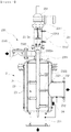
- FIG. 3 is a sectional view showing a filtering unit of the ballast water treatment device according to an embodiment of the present invention
- FIG. 4 is an exploded perspective view showing a vortex generating unit according to an embodiment of the present invention
- FIG. 5 is a partially cutaway perspective view showing a vortex generating unit according to another embodiment of the present invention
- FIG. 6 is a side view showing a vortex generating unit according to a further embodiment of the present invention
- FIG. 7 is a partially cutaway exploded perspective view showing an ultraviolet treatment unit of the ballast water treatment device according to an embodiment of the present invention
- FIG. 8 is a side view showing a protective screen according to an embodiment of the present invention
- FIGS. 9A to 9D are sectional views taken along lines A-A', B-B', C-C', and D-D' of FIG. 8
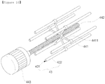
- FIG. 10 is a perspective view showing a washing unit of the ultraviolet treatment unit.
- a ballast water treatment device includes a filtering unit 2, a vortex generating unit 3, an ultraviolet treatment unit 4, and a control unit 5.
- the filtering unit 2 filters ballast water, which is taken from an intake pump 1 of a ship, using a filter.
- the vortex generating unit 3 generates an artificial vortex in the ballast water filter by the filtering unit 2.
- the ultraviolet treatment unit 4 sterilizes the ballast water discharged from the vortex generating unit 3, using ultraviolet rays.
- the control unit 5 controls the overall operation of the filtering unit 2 and the ultraviolet treatment unit 4.
- the filtering unit 2 functions to filter the ballast water taken from the intake pump 1 of the ship, using the filter.
- the filtering unit 2 includes a body 21, a filter 22, an automatic washing unit 23, and a pressure sensor 24.
- the body 21 has an inlet 211 and an outlet 212 to permit the inflow and outflow of the ballast water.
- the filter 22 filters the ballast water which flows in the body 21.
- the automatic washing unit 23 functions to wash away foreign substances adhering to the filter 22.
- the pressure sensor 24 measures pressure at the inlet 211 and the outlet 212.
- the body 21 defines the body of the filtering unit 2, and may preferably have the shape of a cylinder that has a space therein.
- the body 21 includes the inlet 211 into which the ballast water put into the ship is introduced, and the outlet 212 through which filtered ballast water is discharged.
- a filtering operation is performed using the filter 22 which is provided to surround the interior of the body 21.
- the inlet 211 be located at a lower position of the body 21 and the outlet 212 be located above the inlet 211 so that ballast water flowing to the lower portion of the body 21 is filtered while filling the interior of the body 21.
- the filter 22 functions to filter the ballast water introduced into the body 21 through the inlet 211, and may preferably have a cylindrical shape along the inner circumference of the body 21 to surround the interior of the body 21.
- the ballast water in order to discharge the ballast water, which flows through the inlet 211 into the body 21, through the outlet 212, the ballast water must necessarily pass through the filter 22. While the ballast water is filtered by the filter 22, organisms and particles having size over 50 ⁇ m are removed. In the case of continuously performing the filtering operation, foreign substances accumulate in the inner surface of the filter 22, so that the filtering function is deteriorated and thus the operation of removing foreign substances is performed by the automatic washing unit 23 that will be described below.
- the automatic washing unit 23 serves to automatically remove foreign substances from the filter 22 under the control of the control unit 5 using a difference in pressure between the inside and the outside of the filter 22.
- the automatic washing unit 23 includes a driving unit 231, a suction unit 232, and an exhaust unit 233.
- the driving unit 231 drives the automatic washing unit 23 in response to a signal of the control unit 5.
- the suction unit 232 is connected to the driving unit 231 to be moved by the driving unit 231, and sucks foreign substances adhering to the filter 22.
- the exhaust unit 233 functions to discharge foreign substances from the suction unit 232.
- the driving unit 231 serves to provide the power that operates the automatic washing unit 23, and includes a driving motor 2311, a driving shaft 2312, and limit switches 2313.
- the driving motor 2311 provides the power that operates the automatic washing unit 23, and may comprise a general motor.
- the driving motor 2311 is automatically operated under the control of the control unit 5.
- the driving shaft 2312 connects a core that will be described below with the driving motor 2311, and vertically moves and rotates the core by the operation of the driving motor 2311.
- the outer circumference of one end of the driving shaft 2312 connected to the driving motor 2311 may have the shape of thread. This allows the driving shaft 2312 to move up and down and rotate as the driving motor 2311 is operated, thus more efficiently sucking foreign substances from the filter 22.
- a contact means 2312a is provided on a predetermined portion of the driving shaft 2312.
- the contact means 2312a comes into contact with the limit switches 2313 that will be described below and limit the vertical moving distance of the driving shaft 2312, and may comprise a disc-shaped rubber member or metal member.
- a pair of limit switches 2313 is located at an upper position in the body 21.
- the contact means 2312a comes into contact with each limit switch 2313, the direction in which the driving shaft 2312 moves is changed.
- the driving shaft 2312 vertically moves for a distance between the limit switches 2313.
- the suction unit 232 is connected to the driving unit 231 and is moved to suck foreign substances from the filter 22.
- the suction unit 232 includes suction rods 2321 which suck foreign substances from the filter 22foreign substances, and a core 2322 which is connected to the suction rods 2321 to move the sucked foreign substances.
- Each suction rod 2321 functions to suck foreign substances from the inner surface of the filter 22, and has the shape of a rod or bar which has a through hole therein.
- One end of the suction rod 2321 is in close contact with the inner surface of the filter 22 to suck foreign substances from the inner surface of the filter 22.
- the diameter of the through hole of one end of the suction rod 2321 is small.
- the other end is connected to the core 2322 to move the sucked foreign substances to the core 2322.
- a plurality of suction rods 2321 may be radially attached to the outer circumference of the core 2322 in such a way as to be located at different heights.
- the core 2322 is connected to the suction rods 2321 to move the sucked foreign substances.
- the core 2322 may have the shape of a rod or bar which is hollow therein, and the suction rods 2321 are radially attached to the outer circumference of the core 2322. Thereby, the foreign substances sucked through the suction rods 2321 may move through the internal space of the core 2322.
- Exhaust holes 2322a are formed in one end of the core 2322 so that foreign substances flowing through the internal space are discharged to the flushing chamber 2331 of the exhaust unit 233.
- one end of the core 2322 is connected to the driving shaft 2312, so that the core 2322 may perform rotary movement as well as vertical movement when the driving shaft 2312 moves.
- the principle of moving foreign substances in the core 2322 uses the flow of ballast water caused by a difference in pressure between high pressure in the filter 22 and low pressure in each suction rod 2321 or the core 2322, which will be described below in detail.
- the exhaust unit 233 functions to discharge foreign substances from the suction unit 232.
- the exhaust unit 233 includes a flushing chamber 2331, an exhaust pipe 2332, and an exhaust valve 2333.
- the flushing chamber 2331 stores foreign substances which are discharged through the exhaust holes 2322a formed in one end of the core 2322.
- the exhaust pipe 2332 is the passage through which the foreign substances of the flushing chamber 2331 are discharged.
- the exhaust valve 2333 is formed at a position of the exhaust pipe 2332.
- the flushing chamber 2331 is the part in which foreign substances discharged through the exhaust holes 2322a of the core 2322 accumulate.
- the size and shape of the flushing chamber 2331 are set in consideration of the distance the core 2322 moves up and down so that the flushing chamber 2331 may store foreign substances discharged from the exhaust holes 2322a of the core 2322 in any circumstance.
- the exhaust pipe 2332 is the passage through which the foreign substances of the flushing chamber 2331 are discharged, and may have the shape of a pipe which is connected to a side of the flushing chamber 2331.
- the exhaust valve 2333 is connected to a side of the exhaust pipe 2332 and provides the suction force that sucks foreign substances from the filter 22 and discharges them.
- the exhaust valve 2333 is controlled by the control unit 4. That is, when the exhaust valve 2333 is open, the interiors of the exhaust pipe 2332, the flushing chamber 2331, the core 2322 and the suction rods 2321 have atmospheric pressure, that is, are at a pressure lower than the high pressure in the filter 22. The ballast water inside the filter 22 is sucked into the suction rods 2321 which are at low pressure. At this time, foreign substances adhering to the filter 22 are also sucked. Meanwhile, when the exhaust valve 2333 is closed, the suction of ballast water and foreign substances is stopped. The whole operating principle will be described below.
- the pressure sensor 24 is used to measure pressure inside and outside the filter 22, and may comprise general pressure measuring sensors. If a difference in pressure between the inside and outside of the filter 22 measured by the pressure sensor 24 exceeds a predetermined range, the operation of the automatic washing unit 23 for removing foreign substances from the filter 22 is started under the control of the control unit 4.
- ballast water flowing through the inlet 211 into the body 21 is filtered by the filter 22 and then is discharged through the outlet 212.
- the filter 22 is filtered by the filter 22 and then is discharged through the outlet 212.
- the internal pressure of the filter 22 measured by the pressure sensor 24 increases. If the increment exceeds a predetermined range, the automatic washing unit 23 is operated under the control of the control unit 4. If the control unit 4 operates the driving motor 2311, the driving shaft 2312, the core 2322 and the suction rods 2321 perform vertical movement and rotary movement.
- ballast water and foreign substances in the filter 22 are sucked through the suction rods 2321, and then are discharged through the core 2322, the flushing chamber 2331 and the exhaust pipe 2332. Further, if the internal pressure of the filter 22 is decreased below a predetermined range, the automatic washing unit 23 stops operating.
- One of the important features of the ballast water treatment device according to the present invention is that the filter 22 of the filtering unit 2 can continue the filtering operation even while the automatic washing unit 23 is operating.
- the vortex generating unit 3 functions to generate vortex in ballast water which is filtered by the filtering unit 2.
- the vortex generating unit 3 includes a body 31 in and out of which ballast water flows, and a vortex generator 32 which is coupled to the interior of the body 31 to generate a vortex in the ballast water flowing in the body 31.
- the body 31 defines the body of the vortex generating unit 3, and may preferably have the shape of a cylinder that has a space therein.
- the body 31 includes an inlet 311 into which ballast water flows, an outlet 312 through which ballast water having a vortex is discharged, and a locking step 313 which is provided between the inlet 311 and the outlet 312 in such a way as to protrude from the inner circumference of the body 31 and is coupled to the vortex generator 32 that will be described below.
- the locking step 313 protrudes from the inner circumference of the body 31, is coupled to the vortex generator 32 which will be described below, and has fastening holes 3131 so that screws can fasten it to the vortex generator 32.
- the vortex generator 32 is coupled to a surface of the locking step 313 which is located at the ballast-water inlet side of the body 31, using screws or by welding, and generates a vortex in ballast water flowing in the body 31.
- the vortex generator 32 includes a plurality of blades 321 which are formed by cutting a portion from the central portion of a circular metallic thin plate to a predetermined radius and bending the portion in the form of a propeller, a through hole 322 which is formed in the metallic thin plate as a result of the formation of the blades 321, and a frame 323 which is provided around the blades 321.
- the blades 321 are formed in the central portion of the frame 323, and are formed by cutting a surface of a predetermined radius corresponding to the through hole 322 in such a way as to be connected to the frame 323 and bending the surface in the form of a propeller in such a way as to have the same inclination.
- Each blade 321 includes a neck 3211 which is connected to the frame 323 and bent at a predetermined angle, and a blade face 3212 which extends from the neck 3211 to the center of the through hole 322, protrudes in such a way as to be inclined at a predetermined angle in the direction in which ballast water flows, and has the shape of a curved surface.
- the angle of the blade face 3212 is inclined at an angle of 20° to 40° in the direction in which ballast water flows.
- a plurality of slits 3213 is formed in the blade face 3212 to prevent the neck 3211 from being easily damaged when excessive pressure is exerted on the blade 321 by the ballast water flowing in and out.
- the ballast water flowing in the body 31 collides with the blade 321 and rotates in a direction in which the blade 321 is inclined, thus generating a vortex. The generation of the vortex in the ballast water which flows into the vortex generating unit 3 will be described below in detail.
- the through hole 322 is a hole formed in the metallic thin plate when the blades 321 are formed, and makes the ballast water flowing into the body 31 pass through the vortex generator 32.
- the frame 323 is provided around the blades 321 in a circular shape, and is coupled to the locking step 313. Fastening holes 3231 are formed in the frame 323 so that the frame 323 can be fastened to the locking step 313 by screws.
- the principle used to generate a vortex in the ballast water flowing into the vortex generating unit 32 using the vortex generating unit 3 constructed as described above is as follows. That is, the ballast water passing through the filtering unit 2 flows through the inlet 311 into the body 31 of the vortex generating unit 3. The ballast water introduced into the body 31 passes through the vortex generator 32 while flowing to the outlet 312. The ballast water passing through the through hole 322 of the vortex generator 32 collides with the blades 321, so that the direction in which the ballast water flows is changed in the direction in which the blades 321 are inclined. Since the blades 321 are formed in the shape of a propeller, the ballast water colliding with the blades 321 is rotated and a vortex is generated.
- the ballast water in which the vortex is formed is discharged out through the outlet 312 and enters the ultraviolet treatment unit 4. Since a vortex is formed in the ballast water, the ballast water moves while swirling. Thus, the ballast water mixes well, so that a large quantity of ultraviolet rays is uniformly radiated onto the ballast water entering the ultraviolet treatment unit 4 and thus the ballast water treatment device has a high sterilization effect. Further, if a large pressure is exerted on the blades 321 colliding with the ballast water, so that the blades 321 are damaged, the vortex generator 32 can be easily replaced by a new one because the vortex generator 32 is detachably attached to the body 31 in a screw-type fastening method. Therefore, the maintenance of the vortex generator 32 can be easily performed.
- ballast water is uniformly mixed by vortex, so that the length of a pipe from the filtering unit 2 to the ultraviolet treatment unit 4 can be reduced, and thus the compactness of the device is achieved.
- a ballast water treatment device will be described with reference to FIG. 5 .
- a vortex generating unit 3' includes a body 31' in and out of which ballast water flows, and blades 32' which are formed in the body 31' to generate a vortex in the ballast water flowing in the body 31'.
- the body 31' is equal to the body 31 of the vortex generating unit 3 shown in FIG. 4 except that the blades 32' are coupled to the body 31' without using the locking step 313.
- a plurality of blades 32' collides with the ballast water flowing in the body 31' to generate a vortex, and is integrally formed on the inner surface of the body 31' in such a way as to be inclined at a predetermined angle.
- Each blade 32' is made of a metallic plate having a predetermined length and has the shape of a curved surface which is formed such that its width is reduced from both sides to the center.
- a plurality of slits 321' is formed in each blade 32' so as to prevent the blade 32' from separating from the body 31' when the blade 32' collides with the ballast water and thus excessive pressure is exerted on the blade 32'.
- the vortex generating unit 3" includes a body 31" in and out of which ballast water flows, and a plurality of curved blades 32" which are formed on the inner circumference of the body 31".
- one or more blades may be formed on the inner circumference of a body in a spiral shape.
- the ultraviolet treatment unit 4 functions to sterilize ballast water, discharged from the vortex generating unit 3, using ultraviolet rays.
- the ultraviolet treatment unit 4 includes a body 41, a protective screen 42, an ultraviolet lamp unit 43, a washing unit 44, an ultraviolet intensity meter 45, and a temperature sensor 46. Ballast water flows in and out of the body 41.
- the protective screen 42 is provided in the body 41 to generate a vortex in the ballast water flowing into the body 41 and remove foreign substances such as shells from the ballast water, thus protecting a sleeve 432 which surrounds an ultraviolet lamp.
- the ultraviolet lamp unit 43 includes an ultraviolet lamp 431 which radiates ultraviolet rays onto the ballast water passing through the protective screen 42.
- the washing unit 44 removes foreign substances from the ultraviolet lamp unit 43.
- the ultraviolet intensity meter 45 measures the intensity of the ultraviolet rays emitted from the ultraviolet lamp 431.
- the temperature sensor 46 functions to measure the internal temperature of the body 41. As necessary, a plurality of ultraviolet treatment units 4 may be continuously installed in series.
- the body 41 defines the body of the ultraviolet treatment unit 4, and may preferably have the shape of a cylinder which has a space therein.
- the body 41 includes an inlet 411 into which ballast water flows, an outlet 412 through which sterilized ballast water is discharged, and a locking step 413 which is provided around the inlet 411 in such a way as to protrude from the inner circumference of the body 41 and is coupled to the protective screen 42 that will be described below.
- the inlet 411 and the outlet 412 may be formed in a side surface of the cylindrical body 41 in order to increase the effect of sterilizing ballast water passing through the ultraviolet lamp unit 43.
- the locking step 413 protrudes from the inner circumference of the body 41 around the inlet 411 and is coupled to the protective screen 42 that will be described below.
- the locking step 413 has fastening holes 4131 so that it can be fastened to the protective screen 42 using screws.
- the protective screen 42 is coupled to a surface of the locking step 413 located at a ballast-water inlet side of the body 41, using screws or by welding, and generates a vortex in the ballast water introduced into the body 41 and removes foreign substances including shells from the ballast water, thus protecting the sleeve 432 that surrounds the ultraviolet lamp 431.
- the protective screen 42 includes a frame 421 which forms an outer support and a mesh net 422 which is formed inside the frame 421.
- the frame 421 forms the outer support in a circular shape, and is coupled to the locking step 413.
- Fastening holes 4211 are formed in the frame 321 so that the locking step 413 is coupled to the frame 421 using screws.
- the mesh net 422 is formed in the frame 421 and includes lateral ribs 4221 and longitudinal ribs 4222 which cross each other, with through holes 4223 being formed between the ribs that cross each other.
- Each of the ribs 4221 and 4222 forming the mesh net 422 is made of a rectangular plate which is long, and the lateral ribs 4221 or the longitudinal ribs 4222 are installed to have directivity, for example, to be inclined so that the ribs 4221 or 4222 collide with the ballast water flowing into the inlet 411 and change the direction in which the ballast water moves, thus generating a vortex.
- portion a when the mesh net 422 is divided into four portions, in portion a, the longitudinal ribs 4222 are installed vertically but the lateral ribs 4221 are obliquely installed at a predetermined angle in the direction of 12 o'clock. In portion b, the lateral ribs 4221 are installed vertically but the longitudinal ribs 4222 are inclined at a predetermined angle in the direction of 9 o'clock. In portion c, the longitudinal ribs 4222 are installed vertically but the lateral ribs 4221 are inclined at a predetermined angle in the direction of 6 o'clock.
- the lateral ribs 4221 are installed vertically but the longitudinal ribs 4222 are inclined at a predetermined angle in the direction of 3 o'clock. It is preferable that the lateral or longitudinal ribs 4221 or 4222 of the mesh net 422 be inclined at an angle of 20 to 40 degrees.
- the principle according to which a vortex is generated in the ballast water passing through the protective screen 42 is as follows.
- the ballast water passing through portion a collides with the lateral ribs 4221 which are obliquely installed in the 12 o'clock direction, so that the direction in which the ballast water moves changes into the 12 o'clock direction.
- the ballast water passing through portion b collides with the longitudinal ribs 4222 which are obliquely installed in the 9 o'clock direction, so that the direction in which the ballast water moves changes into the 9 o'clock direction.
- the ballast water passing through portion c collides with the longitudinal ribs 4222 which are obliquely installed in the 6 o'clock direction, so that the direction in which the ballast water moves changes into the 6 o'clock direction.
- the ballast water passing through portion d collides with the lateral ribs 4222 which are obliquely installed in the 3 o'clock direction, so that the direction in which the ballast water moves changes into the 3 o'clock direction. Consequently, the ballast water passing through the protective screen 42 rotates counterclockwise, so that a vortex is generated. As such, a vortex is generated in the ballast water, so that the ballast water moves while swirling and thus the ballast water mixes well.
- the sleeve 432 may collide with foreign substances, such as shells, flowing into the body 4 along with the ballast water and thus be damaged. While foreign substances such as shells introduced into the body 4 along with the ballast water are passing through the protective screen 42, the foreign substances are filtered by the protective screen 42 and thus the sleeve 432 is protected.
- the ultraviolet lamp unit 43 emits ultraviolet rays and radiates them into the ballast water flowing into the body 41.
- the ultraviolet lamp unit 43 includes the ultraviolet lamp 431 and the sleeve 432.
- the ultraviolet lamp 431 having the shape of a rod or bar is positioned in the body 41.
- a plurality of ultraviolet lamps 431 may be placed at regular intervals in the cylindrical body 41 in such a way as to be parallel to the body 41 in an axial direction thereof.
- the ballast water flowing through the inlet 411 and the outlet 412 may pass by perpendicular to the ultraviolet lamps 431.
- the sleeve 432 surrounding the ultraviolet lamp 431 protects the ultraviolet lamp 431. If foreign substances adhere to a surface of the sleeve 432, the intensity of the emitted ultraviolet rays is reduced. Thus, the surface of the sleeve 432 is washed by the washing unit 44.
- the sleeve 432 may use a pipe which is made of quartz.
- the washing unit 44 functions to remove foreign substances from the surface of the sleeve 432.
- the washing unit 44 includes a wiper 441 which is attached to the outer circumference of the sleeve 432, a driving shaft 442 which is connected to the wiper 441, and a driving motor 443 which is connected to the driving shaft 442 to actuate the driving shaft 442.
- the wiper 441 functions to remove foreign substances from the outer circumference of the sleeve 432, and may preferably have an annular shape which surrounds the entire outer circumference of the sleeve 432.
- the wiper 441 may be made of synthetic resin or synthetic rubber having heat resistance. If there is a plurality of sleeves 432, a plurality of wipers 441 is required. In this case, the wipers 441 may be connected to each other via arms 4411, and the arms 4411 may be connected to the driving shaft 442.
- the driving shaft 442 is connected to the wiper 441 and moves the wiper 441 so that it can remove foreign substances from the outer circumference of the sleeve 432.
- the driving shaft 442 may be provided in the central portion of the body 41 in such a way as to be parallel to the body 41 in the axial direction thereof, and the outer circumference of the driving shaft 442 may have thread.
- the driving shaft 442 is connected at an end thereof to the driving motor 443.
- the driving motor 443 is connected to one end of the driving shaft 442 to provide power that operates the driving shaft 442 and the wiper 441.
- the driving motor 443 may comprise a general motor.
- the ultraviolet intensity meter 45 functions to measure the intensity of the ultraviolet rays emitted from the ultraviolet lamp 431, and may be provided on the outer circumference of the body 41 in such a way as to pass through the body 41. Since the ultraviolet intensity meter 45 is connected to the control unit 5, the control unit 5 operates the washing unit 44 when the intensity of the measured ultraviolet rays is less than a predetermined range. The operating principle will be described below in detail.
- the temperature sensor 46 functions to measure the internal temperature of the body 41 of the ultraviolet treatment unit 4, and may be provided on the outer circumference of the body 41 or provided in the body 41. Since the temperature sensor 46 is connected to the control unit 5, the control unit 5 stops operating the ultraviolet treatment unit 4 if the internal temperature of the body 41 exceeds a predetermined range.
- the operating principle of the ultraviolet treatment unit 4 including the above components will be described below.
- the ballast water is sterilized by the ultraviolet rays which are radiated from the ultraviolet lamp 431, prior to being discharged through the outlet 412. At this time, if foreign substances adhere to the surface of the sleeve 432 surrounding the ultraviolet lamp 431, the intensity of the ultraviolet rays emitted from the ultraviolet lamp 431 is reduced.
- the washing unit 44 is operated under the control of the control unit 5.
- the control unit 5 functions to control the overall operation of the filtering unit 2 and the ultraviolet treatment unit 4. As described above, the control unit 5 is connected to the automatic washing unit 23, the pressure sensor 24, the washing unit 44, the ultraviolet intensity meter 45, and the temperature sensor 46, and transmits signals from and to the above components, thus controlling the overall operation. The control unit 5 may further function to store data and transmit a warning message.
- a display unit 6 may be further provided, which is connected to the control unit 5 to display the operation of the ballast water treatment device.
- the display unit 6 allows a person concerned to easily visually check the condition of the automatic washing unit 23, the pressure sensor 24, the washing unit 44, the ultraviolet intensity meter 45, and the temperature sensor 46 which are operated under the control of the control unit 5, and the condition of the ballast water which is treated by the filtering unit 2 and the ultraviolet treatment unit 4.
- the ballast water treatment device physically filters ballast water using the filter, generates a vortex in the filtered ballast water, and thereafter sterilizes the ballast water using ultraviolet rays, thus preventing secondary contamination attributable to by-products, and preventing the contamination of a ballast tank.
- the automatic washing of the filtering unit or the ultraviolet treatment unit is possible, so that performance is kept constant and maintenance can be effectively performed.
- the filtering unit or the ultraviolet treatment unit may be automatically washed without stopping treating the ballast water, so that the efficiency of treatment is increased, and thus it is effective in terms of treatment time and cost.
- the automatic washing unit of the filtering unit is constructed to simultaneously perform vertical movement and rotary movement, thereby improving the washing ability of the filter.
- the vortex generating unit is included to uniformly mix the ballast water, thus improving a sterilization effect.
- a distance from the center of the filter to the center of the ultraviolet lamp 431 is within 1.5m. Therefore, the miniaturization of the ballast water treatment device is achieved, so that an area in which the device is installed can be minimized.
- the ballast water treatment device may further include a bypass duct 7 between the filtering unit 2 and the vortex generating unit 3 so that the ballast water flows through only either of the filtering unit 2 or the ultraviolet treatment unit 4 to be treated, as necessary.
- the bypass duct 7 allows ballast water to flow between the filtering unit 2 and the vortex generating unit 3. Ballast water is treated while passing sequentially through the filtering unit 2 and the ultraviolet treatment unit 4. However, if the bypass duct 7 is installed, the ballast water may pass through only either of the filtering unit 2 or the ultraviolet treatment unit 4 to be treated, as necessary. Particularly in the case of discharging the ballast water stored in the ballast tank 8 to the sea, it is unnecessary for the ballast water to pass through the filtering unit 2. Thus, the ballast water can be discharged after passing through only the ultraviolet treatment unit 4, so that it is effective in terms of treatment time and cost.
- ballast water introduced into the ballast water treatment device when it is being stored in the ballast tank 8 will be described with reference to FIG. 2 . If it is unnecessary to sterilize and filter the introduced ballast water, a first valve 11, a third valve 13, and a fourth valve 14 are closed and a fifth valve 15 is open, so that the ballast water may be directly stored in the ballast tank 8. If it is necessary to filter and sterilize the introduced ballast water, the third and fifth valves 13 and 15 are closed, and the first, second, and fourth valves 11, 12, and 14 are open, so that the introduced ballast water may be stored in the ballast tank 8 after passing through the filtering unit 2 and the ultraviolet treatment unit 4.
- the first, second, and fifth valves 11, 12, and 15 are closed, and the fourth and fifth valves 13 and 14 are open, so that the introduced ballast water may be stored in the ballast tank 8 after having passed through the ultraviolet treatment unit 4.
- ballast water treatment device right after ballast water containing 5 or more species of microorganisms and bacteria that belong to 3 different phyla has been treated by the ballast water treatment device according to the present invention, and when 5 days have passed after the treated ballast water was stored in the ballast tank, the ballast water is collected and the quantity of remaining microorganisms (is measured.
- ballast water containing 5 or more species of microorganisms and bacteria that belong to 3 different phyla is stored in the ballast tank without undergoing any additional treatment, and when 5 days have passed after the ballast water was stored in the ballast tank, the water is collected and the quantity of remaining microorganisms is measured.
- the control group yields the following results. That is, as for 1 microorganisms having size over 50 ⁇ m, they are reduced from an initial value, 250,000 Ind/m3, to 223,000 Ind/m3, and after 5 days have passed, they are reduced to 126,000 Ind/m3. As a result, the residual rate of the microorganisms exceeds 50%. As for 2 microorganisms of 10 to 50 ⁇ m, they are reduced from an initial value, 5,000 Ind/m3, to 4,300 Ind/m3, and after 5 days have passed, they are reduced to 3,600 Ind/m3. As a result, the residual rate of the microorganisms exceeds 70%. Further, as for 3 bacteria, they are reduced from an initial value, 2,700 cfu/100ml to 1,800 cfu/100ml, and after 5 days have passed, they are present in the remaining quantity of 235 cfu/100ml.
- the study group yields the following results. That is, as for 1 microorganisms having size over 50 ⁇ m, the microorganisms having the initial value of 250,000 Ind/m3 are reduced to 600 Ind/m3 after treatment, and are reduced to 0 Ind/m3 after 5 days have passed. As such, the residual rate of the microorganisms is 0%, which perfectly satisfies the IMO requirements requiring 10 Ind/m3 or less. As for 2 microorganisms of 10 to 50 ⁇ m, the microorganisms having the initial value of 5,000 Ind/m3 are reduced to 200 Ind/m3 after treatment, and are reduced to 0 Ind/m3 after 5 days have passed.
- the residual rate of the microorganisms is 0%, which perfectly satisfies the IMO requirements requiring 10 Ind/m3 or less.
- the bacteria having the initial value of 2,700 cfu/100ml are reduced to 23 cfu/100ml after treatment, and are present in the remaining quantity of 7 cfu/100ml after 5 days have passed. Consequently, it can be seen that the remaining quantity of the bacteria perfectly satisfies the IMO requirements requiring 250 cfu/100ml or less.
- Organism Type unit Initial Control Day 0 Control Day 5 Treated Day 0 Treated Day 5 IMO Req Organisms > 5 0 ⁇ m Ind/m3 250,000 223,000 126,000 600 0 >10 Organisms 10-50 ⁇ m Ind/m3 5,000 4,300 3,600 200 0 >10 E-coli bacteria Cfu/100ml 2,700 1,800 235 23 0 >250
- the present invention provides a ballast water treatment device, which uses a method of physically filtering ballast water using a filter and a method of sterilizing the ballast water using ultraviolet rays in combination, thus preventing secondary contamination resulting from by-products, preventing a ballast tank from becoming contaminated, affording effective maintenance, and making it convenient to control.
- the present invention provides a ballast water treatment device, which includes a vortex generating unit between a filtering unit and an ultraviolet treatment unit to generate an artificial vortex in ballast water fed from the filtering unit and thus allow the ballast water to be uniformly mixed, thus enabling a large quantity of ultraviolet rays to be radiated onto the ballast water which is passing through the ultraviolet treatment unit, therefore improving a sterilization effect.
- the present invention provides a ballast water treatment device, which includes a vortex generating unit that uniformly mixes the ballast water and thus improves a sterilization effect, thus enabling a distance between the center of a filter and the center of an ultraviolet lamp to be set to 1.5m or less, therefore realizing the miniaturization of the ballast water treatment device and minimizing the area in which the device is installed.
- the present invention provides a ballast water treatment device, in which an ultraviolet treatment unit includes a protective screen to generate a vortex in the ballast water entering the ultraviolet treatment unit, thus enabling a large quantity of ultraviolet rays to be radiated onto the ballast water so as to improve a sterilization effect, and thus removing foreign substances such as a shell from the ballast water so as to protect a sleeve which surrounds an ultraviolet lamp.
- the present invention provides a ballast water treatment device, which further includes a bypass duct between a filtering unit and a vortex generating unit so that ballast water passes through only either of the filtering unit or the ultraviolet treatment unit to be treated, as necessary.
- the present invention provides a ballast water treatment device, which allows a filtering unit or an ultraviolet treatment unit to be automatically washed, thus always maintaining uniform performance, and affording efficient maintenance.
- the present invention provides a ballast water treatment device, which allows a filtering unit or an ultraviolet treatment unit to be automatically washed without stopping treating ballast water, thus increasing treatment efficiency, therefore being efficient in terms of treatment time and cost.
- the present invention provides a ballast water treatment device, which is constructed to allow an automatic washing unit of a filtering unit to simultaneously perform vertical movement and rotary movement, thus increasing the washing ability of a filter.
Landscapes
- Chemical & Material Sciences (AREA)
- Chemical Kinetics & Catalysis (AREA)
- Engineering & Computer Science (AREA)
- Environmental & Geological Engineering (AREA)
- Toxicology (AREA)
- Health & Medical Sciences (AREA)
- Organic Chemistry (AREA)
- Water Supply & Treatment (AREA)
- Hydrology & Water Resources (AREA)
- Life Sciences & Earth Sciences (AREA)
- General Health & Medical Sciences (AREA)
- Public Health (AREA)
- Combustion & Propulsion (AREA)
- Mechanical Engineering (AREA)
- Ocean & Marine Engineering (AREA)
- Physical Water Treatments (AREA)
Description
- The present invention relates generally to a ballast water treatment device and, more particularly, to a ballast water treatment device which includes a filtering unit filtering ballast water introduced into a ship using a filter, a vortex generating unit generating an artificial vortex in the ballast water filtered by the filtering unit, and an ultraviolet treatment unit having an ultraviolet lamp which sterilizes the ballast water discharged from the vortex generating unit using ultraviolet rays, thus preventing secondary contamination resulting from by-products, preventing a ballast tank from becoming contaminated, affording effective maintenance, and making it convenient to control, and in which an artificial vortex is formed in the ballast water when it is mixed, thus allowing a large quantity of ultraviolet rays to be radiated onto the ballast water passing through the ultraviolet treatment unit, therefore improving a sterilization effect.
- After goods are unloaded from a ship, the ship does not rest sufficiently deep in the water, so that it is apt to lose its balance. Further, a propeller or the like is not sufficiently immersed in the water, so that the propeller does not operate efficiently. Thus, in order for the ship to maintain its balance while sailing without goods, seawater is put into a tank of the ship. Such seawater is called ballast water. The increasing volume of internal trade has led to an increase in the ratio of marine transportation using a ship that can transport a large amount of goods, and the size of the ship also has been increasing rapidly. Thus, the volume of ballast water used in the ship is also increasing considerably. As the volume of the ballast water used in the ship increases, the damage done to the endemic marine ecosystem resulting from it being attacked by exotic marine organism species is also increasing. In order to solve the international environmental contamination problem, the Internal Maritime Organization (IMO) completed the 'International treaty concerning control and management of ballast water and sediment of ships' in 2004, which is effective from 2009.
- As a conventional method of treating ballast water, a land treatment method was used but is ineffective. Thus, a method of installing a ballast water treatment system in a ship has been widely used. The ballast water treatment system mainly uses filtering, heat treatment, chemical treatment, electrolysis, ozone treatment or ultraviolet ray radiation, etc. Document
KR100797186B - However, the heat treatment is problematic in that it is difficult to treat microorganisms or inorganic sources of contamination which are resistant to heat. The chemical treatment is problematic in that secondary contamination may occur after ballast water has been treated. Further, the electrolysis or ozone treatment is problematic in that an explosion may be caused by a short circuit and it is inefficient to manage. Especially, the filtering is problematic in that sediment must be removed from a filter and the operation of treating ballast water must be halted when the sediment is being removed. Further, the ultraviolet ray radiation is problematic in that its efficiency is low because of foreign substances adhering to the surface of a sleeve which surrounds an ultraviolet lamp. Furthermore, when each of the above methods is individually used, it is difficult to completely treat ballast water. Meanwhile, if all of the above methods are used together, treatment is expensive, so that it is inefficient.
- An apparatus for sterilization and purification of ballast water of a ship is known from reference
KR 100797186 B1 - Accordingly, the present invention has been made keeping in mind the above problems occurring in the prior art, and an object of the present invention is to provide a ballast water treatment device, which uses a method of physically filtering ballast water using a filter and a method of sterilizing the ballast water using ultraviolet rays in combination, thus preventing secondary contamination resulting from by-products, preventing a ballast tank from becoming contaminated, affording effective maintenance, and making it convenient to control.
- Another object of the present invention is to provide a ballast water treatment device, which includes a vortex generating unit between a filtering unit and an ultraviolet treatment unit to generate an artificial vortex in ballast water fed from the filtering unit and thus allow the ballast water to be uniformly mixed, thus enabling a large quantity of ultraviolet rays to be radiated onto the ballast water which is passing through the ultraviolet treatment unit, therefore improving a sterilization effect.
- A further object of the present invention is to provide a ballast water treatment device, which includes a vortex generating unit that uniformly mixes the ballast water and thus improves a sterilization effect, thus enabling a distance between the center of a filter and the center of an ultraviolet lamp to be set to 1.5m or less, therefore realizing the miniaturization of the ballast water treatment device and minimizing the area in which the device is installed.
- Yet another object of the present invention is to provide a ballast water treatment device, in which an ultraviolet treatment unit includes a protective screen to generate a vortex in the ballast water entering the ultraviolet treatment unit, thus enabling a large quantity of ultraviolet rays to be radiated onto the ballast water so as to improve a sterilization effect, and thus removing foreign substances such as a shell from the ballast water so as to protect a sleeve which surrounds an ultraviolet lamp.
- A still further object of the present invention is to provide a ballast water treatment device, which further includes a bypass duct between a filtering unit and a vortex generating unit so that ballast water passes through only either of the filtering unit or the ultraviolet treatment unit to be treated, as necessary.
- An additional object of the present invention is to provide a ballast water treatment device, which allows a filtering unit or an ultraviolet treatment unit to be automatically washed, thus always maintaining uniform performance, and affording efficient maintenance.
- Another object of the present invention is to provide a ballast water treatment device, which allows a filtering unit or an ultraviolet treatment unit to be automatically washed without stopping treating ballast water, thus increasing treatment efficiency, therefore being efficient in terms of treatment time and cost.
- Another object of the present invention is to provide a ballast water treatment device, which is constructed to allow an automatic washing unit of a filtering unit to simultaneously perform vertical movement and rotary movement, thus increasing the washing ability of a filter.
- In order to accomplish the above objects, the present invention provides the embodiments having the following construction.
- According to an embodiment of the present invention, a ballast water treatment device includes a filtering unit filtering ballast water introduced into a ship using a filter, a vortex generating unit generating an artificial vortex in the ballast water filtered by the filtering unit, and an ultraviolet treatment unit having an ultraviolet lamp which sterilizes the ballast water discharged from the vortex generating unit using ultraviolet rays. Thereby, the ballast water is uniformly mixed by the vortex generated by the vortex generating unit, so that a sterilization effect is enhanced, and a distance between the filtering unit and the ultraviolet treatment unit is reduced, so that compactness of the ballast water treatment device is realized.
- According to the present invention, the ballast water treatment device further includes a protective screen which generates a vortex in ballast water and removes foreign substances from the ballast water, thus protecting the ultraviolet treatment unit. The protective screen is provided on a front end of the ultraviolet treatment unit.
- According to a further embodiment of the present invention, the protective screen may include a mesh net formed by crossing lateral and longitudinal ribs with each other, and the lateral and longitudinal ribs may be placed obliquely at a predetermined angle to collide with the ballast water which flows in a body of the ultraviolet treatment unit, thus changing a direction in which the ballast water moves, therefore generating a vortex.
- According to another embodiment of the present invention, the filtering unit may include a body having an inlet and an outlet to permit inflow and outflow of ballast water, a filter filtering the ballast water which flows in the body, and an automatic washing unit washing away foreign substances from the filter.
- According to another embodiment of the present invention, the automatic washing unit may include a driving unit driving the automatic washing unit, a suction unit connected to the driving unit to be moved by the driving unit and sucking the foreign substances from the filter, and an exhaust unit discharging the foreign substances which have been sucked by the suction unit.
- According to another embodiment of the present invention, the driving unit may include a driving motor providing power to actuate the automatic washing unit, and a driving shaft connected to the driving motor. The suction unit may include a suction rod sucking foreign substances from the filter, and a core connected to the suction rod to move the sucked foreign substances and connected to the driving unit. The exhaust unit may include a flushing chamber storing foreign substances which are discharged through an exhaust hole formed in a first end of the core, an exhaust pipe serving as a passage which discharges the foreign substances from the flushing chamber, and an exhaust valve provided at a predetermined position of the exhaust pipe. Thereby, the foreign substances adhering to the filter may be automatically sucked and discharged using a difference in pressure when the exhaust valve is open and closed.
- According to another embodiment of the present invention, the driving shaft may have thread, and the suction rod may be radially connected to the core, so that the suction unit may be moved up and down while being rotated by an operation of the driving unit, thus allowing the foreign substances to be more efficiently sucked from the filter.
- According to another embodiment of the present invention, the vortex generating unit may include a body having an inlet and an outlet to permit inflow and outflow of ballast water and a locking step protruding from an inner circumference of the body, and a vortex generator supported by the locking step and generating a vortex in the ballast water which flows in the body. The vortex generator may include a frame defining an outer support and coupled to the locking step, and a plurality of blades formed by cutting a surface which is on the same plane as the frame to a predetermined radius and bending the cut surface in a predetermined direction.
- According to another embodiment of the present invention, the vortex generating unit may include a body having an inlet and an outlet to permit inflow and outflow of ballast water, and a plurality of blades provided on an inner circumference of the body in such a way as to be inclined at a predetermined angle, so that the ballast water flowing in the body may collide with the blades, thus generating a vortex.
- According to another embodiment of the present invention, the ultraviolet treatment unit may include a body having an inlet and an outlet to permit inflow and outflow of ballast water, an ultraviolet lamp unit having an ultraviolet lamp which radiates ultraviolet rays onto the ballast water flowing in the body, and a washing unit removing foreign substances from the ultraviolet lamp unit.
- According to another embodiment of the present invention, the washing unit may include a wiper wiping an outer circumference of the ultraviolet lamp unit, a driving shaft connected to the wiper, and a driving motor connected to the driving shaft to actuate the driving shaft.
- According to another embodiment of the present invention, the ultraviolet treatment unit may further include an ultraviolet intensity meter measuring intensity of ultraviolet rays emitted from the ultraviolet lamp, and a temperature sensor measuring internal temperature of the body.
- According to another embodiment of the present invention, the ballast water treatment device may further include a bypass duct provided between the filtering unit and the vortex generating unit so that ballast water may pass through only either of the filtering unit or the ultraviolet treatment unit to be treated, as necessary.
- According to another embodiment of the present invention, the ballast water treatment device may further include a display unit displaying an operation of the ballast water treatment device.
- The above and other objects, features and advantages of the present invention will be more clearly understood from the following detailed description taken in conjunction with the accompanying drawings, in which:
-
FIG. 1 is a block diagram showing a ballast water treatment device according to an embodiment of the present invention; -
FIG. 2 is a view showing the coupling relation between a filtering unit, a vortex generating unit and an ultraviolet treatment unit of the ballast water treatment device according to an embodiment of the present invention; -
FIG. 3 is a sectional view showing a filtering unit of the ballast water treatment device according to an embodiment of the present invention; -
FIG. 4 is an exploded perspective view showing a vortex generating unit according to an embodiment of the present invention; -
FIG. 5 is a partially cutaway perspective view showing a vortex generating unit according to another embodiment of the present invention; -
FIG. 6 is a side view showing a vortex generating unit according to a further embodiment of the present invention; -
FIG. 7 is a partially cutaway exploded perspective view showing an ultraviolet treatment unit of the ballast water treatment device according to an embodiment of the present invention; -
FIG. 8 is a side view showing a protective screen according to an embodiment of the present invention; -
FIGS. 9A to 9D are sectional views taken along lines A-A', B-B', C-C', and D-D' ofFIG. 8 ; and -
FIG. 10 is a perspective view showing a washing unit of the ultraviolet treatment unit. - Hereinafter, a ballast water treatment device according to the present invention will be described in detail with reference to the accompanying drawings. The same reference numerals are used throughout the different drawings to designate the same components. Further, when it is determined that the detailed description of the known function and construction may obscure the gist of the present invention, the detailed description will be omitted.
-
FIG. 1 is a block diagram showing a ballast water treatment device according to an embodiment of the present invention,FIG. 2 is a view showing the coupling relation between a filtering unit, a vortex generating unit and an ultraviolet treatment unit of the ballast water treatment device according to an embodiment of the present invention,FIG. 3 is a sectional view showing a filtering unit of the ballast water treatment device according to an embodiment of the present invention,FIG. 4 is an exploded perspective view showing a vortex generating unit according to an embodiment of the present invention,FIG. 5 is a partially cutaway perspective view showing a vortex generating unit according to another embodiment of the present invention,FIG. 6 is a side view showing a vortex generating unit according to a further embodiment of the present invention,FIG. 7 is a partially cutaway exploded perspective view showing an ultraviolet treatment unit of the ballast water treatment device according to an embodiment of the present invention,FIG. 8 is a side view showing a protective screen according to an embodiment of the present invention,FIGS. 9A to 9D are sectional views taken along lines A-A', B-B', C-C', and D-D' ofFIG. 8 , andFIG. 10 is a perspective view showing a washing unit of the ultraviolet treatment unit. - Referring to
FIGS. 1 and2 , a ballast water treatment device according to an embodiment of the present invention includes afiltering unit 2, avortex generating unit 3, an ultraviolet treatment unit 4, and acontrol unit 5. Thefiltering unit 2 filters ballast water, which is taken from anintake pump 1 of a ship, using a filter. Thevortex generating unit 3 generates an artificial vortex in the ballast water filter by thefiltering unit 2. The ultraviolet treatment unit 4 sterilizes the ballast water discharged from thevortex generating unit 3, using ultraviolet rays. Thecontrol unit 5 controls the overall operation of thefiltering unit 2 and the ultraviolet treatment unit 4. - The
filtering unit 2 functions to filter the ballast water taken from theintake pump 1 of the ship, using the filter. Referring toFIG. 3 , thefiltering unit 2 includes abody 21, afilter 22, anautomatic washing unit 23, and apressure sensor 24. Thebody 21 has aninlet 211 and anoutlet 212 to permit the inflow and outflow of the ballast water. Thefilter 22 filters the ballast water which flows in thebody 21. Theautomatic washing unit 23 functions to wash away foreign substances adhering to thefilter 22. Thepressure sensor 24 measures pressure at theinlet 211 and theoutlet 212. - The
body 21 defines the body of thefiltering unit 2, and may preferably have the shape of a cylinder that has a space therein. Thebody 21 includes theinlet 211 into which the ballast water put into the ship is introduced, and theoutlet 212 through which filtered ballast water is discharged. According to the present invention, as will be described below, a filtering operation is performed using thefilter 22 which is provided to surround the interior of thebody 21. Thus, it is preferable that theinlet 211 be located at a lower position of thebody 21 and theoutlet 212 be located above theinlet 211 so that ballast water flowing to the lower portion of thebody 21 is filtered while filling the interior of thebody 21. - The
filter 22 functions to filter the ballast water introduced into thebody 21 through theinlet 211, and may preferably have a cylindrical shape along the inner circumference of thebody 21 to surround the interior of thebody 21. Thus, in order to discharge the ballast water, which flows through theinlet 211 into thebody 21, through theoutlet 212, the ballast water must necessarily pass through thefilter 22. While the ballast water is filtered by thefilter 22, organisms and particles having size over 50µm are removed. In the case of continuously performing the filtering operation, foreign substances accumulate in the inner surface of thefilter 22, so that the filtering function is deteriorated and thus the operation of removing foreign substances is performed by theautomatic washing unit 23 that will be described below. - The
automatic washing unit 23 serves to automatically remove foreign substances from thefilter 22 under the control of thecontrol unit 5 using a difference in pressure between the inside and the outside of thefilter 22. Theautomatic washing unit 23 includes adriving unit 231, asuction unit 232, and anexhaust unit 233. The drivingunit 231 drives theautomatic washing unit 23 in response to a signal of thecontrol unit 5. Thesuction unit 232 is connected to thedriving unit 231 to be moved by the drivingunit 231, and sucks foreign substances adhering to thefilter 22. Theexhaust unit 233 functions to discharge foreign substances from thesuction unit 232. - The driving
unit 231 serves to provide the power that operates theautomatic washing unit 23, and includes a drivingmotor 2311, a drivingshaft 2312, andlimit switches 2313. - The driving
motor 2311 provides the power that operates theautomatic washing unit 23, and may comprise a general motor. The drivingmotor 2311 is automatically operated under the control of thecontrol unit 5. - The driving
shaft 2312 connects a core that will be described below with the drivingmotor 2311, and vertically moves and rotates the core by the operation of the drivingmotor 2311. Particularly, the outer circumference of one end of the drivingshaft 2312 connected to the drivingmotor 2311 may have the shape of thread. This allows the drivingshaft 2312 to move up and down and rotate as the drivingmotor 2311 is operated, thus more efficiently sucking foreign substances from thefilter 22. Further, a contact means 2312a is provided on a predetermined portion of the drivingshaft 2312. The contact means 2312a comes into contact with thelimit switches 2313 that will be described below and limit the vertical moving distance of the drivingshaft 2312, and may comprise a disc-shaped rubber member or metal member. When the contact means 2312a is in contact with eachlimit switch 2313, the moving direction of the drivingshaft 2312 changes under the control of thecontrol unit 5, so that the drivingshaft 2312 moves up and down between the limit switches 2313. - A pair of
limit switches 2313 is located at an upper position in thebody 21. When the contact means 2312a comes into contact with eachlimit switch 2313, the direction in which thedriving shaft 2312 moves is changed. Thus, the drivingshaft 2312 vertically moves for a distance between the limit switches 2313. - The
suction unit 232 is connected to thedriving unit 231 and is moved to suck foreign substances from thefilter 22. Thesuction unit 232 includessuction rods 2321 which suck foreign substances from the filter 22foreign substances, and acore 2322 which is connected to thesuction rods 2321 to move the sucked foreign substances. - Each
suction rod 2321 functions to suck foreign substances from the inner surface of thefilter 22, and has the shape of a rod or bar which has a through hole therein. One end of thesuction rod 2321 is in close contact with the inner surface of thefilter 22 to suck foreign substances from the inner surface of thefilter 22. Preferably, in order to increase the force of suction, the diameter of the through hole of one end of thesuction rod 2321 is small. Further, the other end is connected to thecore 2322 to move the sucked foreign substances to thecore 2322. Further, a plurality ofsuction rods 2321 may be radially attached to the outer circumference of thecore 2322 in such a way as to be located at different heights. This enables foreign substances attached circumferentially and axially to thefilter 22 to be more easily removed when thecore 2322 rotates and moves up and down, thus allowing the entire filter to be washed. The principle wherein thesuction rods 2321 suck foreign substances from thefilter 22 uses the flow of ballast water caused by a difference in pressure between high pressure in thefilter 22 and low pressure in eachsuction rod 2321 or thecore 2322, which will be described below in detail. - The
core 2322 is connected to thesuction rods 2321 to move the sucked foreign substances. Thecore 2322 may have the shape of a rod or bar which is hollow therein, and thesuction rods 2321 are radially attached to the outer circumference of thecore 2322. Thereby, the foreign substances sucked through thesuction rods 2321 may move through the internal space of thecore 2322.Exhaust holes 2322a are formed in one end of thecore 2322 so that foreign substances flowing through the internal space are discharged to theflushing chamber 2331 of theexhaust unit 233. Further, one end of thecore 2322 is connected to the drivingshaft 2312, so that thecore 2322 may perform rotary movement as well as vertical movement when the drivingshaft 2312 moves. The principle of moving foreign substances in thecore 2322 uses the flow of ballast water caused by a difference in pressure between high pressure in thefilter 22 and low pressure in eachsuction rod 2321 or thecore 2322, which will be described below in detail. - The
exhaust unit 233 functions to discharge foreign substances from thesuction unit 232. Theexhaust unit 233 includes aflushing chamber 2331, anexhaust pipe 2332, and anexhaust valve 2333. Theflushing chamber 2331 stores foreign substances which are discharged through theexhaust holes 2322a formed in one end of thecore 2322. Theexhaust pipe 2332 is the passage through which the foreign substances of theflushing chamber 2331 are discharged. Theexhaust valve 2333 is formed at a position of theexhaust pipe 2332. - The
flushing chamber 2331 is the part in which foreign substances discharged through theexhaust holes 2322a of thecore 2322 accumulate. Preferably, the size and shape of theflushing chamber 2331 are set in consideration of the distance thecore 2322 moves up and down so that theflushing chamber 2331 may store foreign substances discharged from theexhaust holes 2322a of thecore 2322 in any circumstance. - The
exhaust pipe 2332 is the passage through which the foreign substances of theflushing chamber 2331 are discharged, and may have the shape of a pipe which is connected to a side of theflushing chamber 2331. - The
exhaust valve 2333 is connected to a side of theexhaust pipe 2332 and provides the suction force that sucks foreign substances from thefilter 22 and discharges them. Theexhaust valve 2333 is controlled by the control unit 4. That is, when theexhaust valve 2333 is open, the interiors of theexhaust pipe 2332, theflushing chamber 2331, thecore 2322 and thesuction rods 2321 have atmospheric pressure, that is, are at a pressure lower than the high pressure in thefilter 22. The ballast water inside thefilter 22 is sucked into thesuction rods 2321 which are at low pressure. At this time, foreign substances adhering to thefilter 22 are also sucked. Meanwhile, when theexhaust valve 2333 is closed, the suction of ballast water and foreign substances is stopped. The whole operating principle will be described below. - The
pressure sensor 24 is used to measure pressure inside and outside thefilter 22, and may comprise general pressure measuring sensors. If a difference in pressure between the inside and outside of thefilter 22 measured by thepressure sensor 24 exceeds a predetermined range, the operation of theautomatic washing unit 23 for removing foreign substances from thefilter 22 is started under the control of the control unit 4. - The operating principle of the
filtering unit 2 including the above components will be described below in detail. First, ballast water flowing through theinlet 211 into thebody 21 is filtered by thefilter 22 and then is discharged through theoutlet 212. At this time, if foreign substances filtered by thefilter 22 adhere to the inner surface of thefilter 22, the internal pressure of thefilter 22 measured by thepressure sensor 24 increases. If the increment exceeds a predetermined range, theautomatic washing unit 23 is operated under the control of the control unit 4. If the control unit 4 operates the drivingmotor 2311, the drivingshaft 2312, thecore 2322 and thesuction rods 2321 perform vertical movement and rotary movement. Further, if the control unit 4 opens theexhaust valve 2333, the internal pressure of eachsuction rod 2321 is lower than the internal pressure of thefilter 22, so that ballast water and foreign substances in thefilter 22 are sucked through thesuction rods 2321, and then are discharged through thecore 2322, theflushing chamber 2331 and theexhaust pipe 2332. Further, if the internal pressure of thefilter 22 is decreased below a predetermined range, theautomatic washing unit 23 stops operating. One of the important features of the ballast water treatment device according to the present invention is that thefilter 22 of thefiltering unit 2 can continue the filtering operation even while theautomatic washing unit 23 is operating. - The
vortex generating unit 3 functions to generate vortex in ballast water which is filtered by thefiltering unit 2. Referring toFIG. 4 , thevortex generating unit 3 includes abody 31 in and out of which ballast water flows, and avortex generator 32 which is coupled to the interior of thebody 31 to generate a vortex in the ballast water flowing in thebody 31. - The
body 31 defines the body of thevortex generating unit 3, and may preferably have the shape of a cylinder that has a space therein. Thebody 31 includes aninlet 311 into which ballast water flows, anoutlet 312 through which ballast water having a vortex is discharged, and a lockingstep 313 which is provided between theinlet 311 and theoutlet 312 in such a way as to protrude from the inner circumference of thebody 31 and is coupled to thevortex generator 32 that will be described below. - The locking
step 313 protrudes from the inner circumference of thebody 31, is coupled to thevortex generator 32 which will be described below, and hasfastening holes 3131 so that screws can fasten it to thevortex generator 32. - The
vortex generator 32 is coupled to a surface of the lockingstep 313 which is located at the ballast-water inlet side of thebody 31, using screws or by welding, and generates a vortex in ballast water flowing in thebody 31. Thevortex generator 32 includes a plurality ofblades 321 which are formed by cutting a portion from the central portion of a circular metallic thin plate to a predetermined radius and bending the portion in the form of a propeller, a throughhole 322 which is formed in the metallic thin plate as a result of the formation of theblades 321, and aframe 323 which is provided around theblades 321. - The
blades 321 are formed in the central portion of theframe 323, and are formed by cutting a surface of a predetermined radius corresponding to the throughhole 322 in such a way as to be connected to theframe 323 and bending the surface in the form of a propeller in such a way as to have the same inclination. Eachblade 321 includes aneck 3211 which is connected to theframe 323 and bent at a predetermined angle, and ablade face 3212 which extends from theneck 3211 to the center of the throughhole 322, protrudes in such a way as to be inclined at a predetermined angle in the direction in which ballast water flows, and has the shape of a curved surface. The angle of theblade face 3212 is inclined at an angle of 20° to 40° in the direction in which ballast water flows. A plurality ofslits 3213 is formed in theblade face 3212 to prevent theneck 3211 from being easily damaged when excessive pressure is exerted on theblade 321 by the ballast water flowing in and out. The ballast water flowing in thebody 31 collides with theblade 321 and rotates in a direction in which theblade 321 is inclined, thus generating a vortex. The generation of the vortex in the ballast water which flows into thevortex generating unit 3 will be described below in detail. - The through
hole 322 is a hole formed in the metallic thin plate when theblades 321 are formed, and makes the ballast water flowing into thebody 31 pass through thevortex generator 32. - The
frame 323 is provided around theblades 321 in a circular shape, and is coupled to the lockingstep 313. Fasteningholes 3231 are formed in theframe 323 so that theframe 323 can be fastened to the lockingstep 313 by screws. - The principle used to generate a vortex in the ballast water flowing into the
vortex generating unit 32 using thevortex generating unit 3 constructed as described above is as follows. That is, the ballast water passing through thefiltering unit 2 flows through theinlet 311 into thebody 31 of thevortex generating unit 3. The ballast water introduced into thebody 31 passes through thevortex generator 32 while flowing to theoutlet 312. The ballast water passing through the throughhole 322 of thevortex generator 32 collides with theblades 321, so that the direction in which the ballast water flows is changed in the direction in which theblades 321 are inclined. Since theblades 321 are formed in the shape of a propeller, the ballast water colliding with theblades 321 is rotated and a vortex is generated. The ballast water in which the vortex is formed is discharged out through theoutlet 312 and enters the ultraviolet treatment unit 4. Since a vortex is formed in the ballast water, the ballast water moves while swirling. Thus, the ballast water mixes well, so that a large quantity of ultraviolet rays is uniformly radiated onto the ballast water entering the ultraviolet treatment unit 4 and thus the ballast water treatment device has a high sterilization effect. Further, if a large pressure is exerted on theblades 321 colliding with the ballast water, so that theblades 321 are damaged, thevortex generator 32 can be easily replaced by a new one because thevortex generator 32 is detachably attached to thebody 31 in a screw-type fastening method. Therefore, the maintenance of thevortex generator 32 can be easily performed. - Further, the ballast water is uniformly mixed by vortex, so that the length of a pipe from the
filtering unit 2 to the ultraviolet treatment unit 4 can be reduced, and thus the compactness of the device is achieved. - A ballast water treatment device according to another embodiment of the present invention will be described with reference to
FIG. 5 . A vortex generating unit 3' includes a body 31' in and out of which ballast water flows, and blades 32' which are formed in the body 31' to generate a vortex in the ballast water flowing in the body 31'. - The body 31' is equal to the
body 31 of thevortex generating unit 3 shown inFIG. 4 except that the blades 32' are coupled to the body 31' without using the lockingstep 313. - A plurality of blades 32' collides with the ballast water flowing in the body 31' to generate a vortex, and is integrally formed on the inner surface of the body 31' in such a way as to be inclined at a predetermined angle. Each blade 32' is made of a metallic plate having a predetermined length and has the shape of a curved surface which is formed such that its width is reduced from both sides to the center. A plurality of slits 321' is formed in each blade 32' so as to prevent the blade 32' from separating from the body 31' when the blade 32' collides with the ballast water and thus excessive pressure is exerted on the blade 32'.
- Further, a
vortex generating unit 3" according to a further embodiment of the present invention will be described with reference toFIG. 6 . Thevortex generating unit 3" includes abody 31" in and out of which ballast water flows, and a plurality ofcurved blades 32" which are formed on the inner circumference of thebody 31". - Although not shown in the drawing, according to another embodiment of the present invention, one or more blades may be formed on the inner circumference of a body in a spiral shape.
- Since the principle of generating a vortex in the ballast water flowing into the vortex generating unit 3' using the vortex generating unit 3' according to the present invention is the same as the principle which has been described with reference to
FIG. 4 , the detailed description of the principle will be omitted herein. - The ultraviolet treatment unit 4 functions to sterilize ballast water, discharged from the
vortex generating unit 3, using ultraviolet rays. Referring toFIGS. 7 to 10 , the ultraviolet treatment unit 4 includes abody 41, aprotective screen 42, anultraviolet lamp unit 43, awashing unit 44, anultraviolet intensity meter 45, and atemperature sensor 46. Ballast water flows in and out of thebody 41. Theprotective screen 42 is provided in thebody 41 to generate a vortex in the ballast water flowing into thebody 41 and remove foreign substances such as shells from the ballast water, thus protecting asleeve 432 which surrounds an ultraviolet lamp. Theultraviolet lamp unit 43 includes anultraviolet lamp 431 which radiates ultraviolet rays onto the ballast water passing through theprotective screen 42. Thewashing unit 44 removes foreign substances from theultraviolet lamp unit 43. Theultraviolet intensity meter 45 measures the intensity of the ultraviolet rays emitted from theultraviolet lamp 431. Thetemperature sensor 46 functions to measure the internal temperature of thebody 41. As necessary, a plurality of ultraviolet treatment units 4 may be continuously installed in series. - The
body 41 defines the body of the ultraviolet treatment unit 4, and may preferably have the shape of a cylinder which has a space therein. Thebody 41 includes aninlet 411 into which ballast water flows, anoutlet 412 through which sterilized ballast water is discharged, and a lockingstep 413 which is provided around theinlet 411 in such a way as to protrude from the inner circumference of thebody 41 and is coupled to theprotective screen 42 that will be described below. Preferably, theinlet 411 and theoutlet 412 may be formed in a side surface of thecylindrical body 41 in order to increase the effect of sterilizing ballast water passing through theultraviolet lamp unit 43. - The locking
step 413 protrudes from the inner circumference of thebody 41 around theinlet 411 and is coupled to theprotective screen 42 that will be described below. The lockingstep 413 hasfastening holes 4131 so that it can be fastened to theprotective screen 42 using screws. - The
protective screen 42 is coupled to a surface of the lockingstep 413 located at a ballast-water inlet side of thebody 41, using screws or by welding, and generates a vortex in the ballast water introduced into thebody 41 and removes foreign substances including shells from the ballast water, thus protecting thesleeve 432 that surrounds theultraviolet lamp 431. Theprotective screen 42 includes aframe 421 which forms an outer support and a mesh net 422 which is formed inside theframe 421. - The
frame 421 forms the outer support in a circular shape, and is coupled to the lockingstep 413. Fastening holes 4211 are formed in theframe 321 so that the lockingstep 413 is coupled to theframe 421 using screws. - The
mesh net 422 is formed in theframe 421 and includeslateral ribs 4221 andlongitudinal ribs 4222 which cross each other, with throughholes 4223 being formed between the ribs that cross each other. Each of theribs mesh net 422 is made of a rectangular plate which is long, and thelateral ribs 4221 or thelongitudinal ribs 4222 are installed to have directivity, for example, to be inclined so that theribs inlet 411 and change the direction in which the ballast water moves, thus generating a vortex. For example, referring toFIGS. 8 and9 , when themesh net 422 is divided into four portions, in portion a, thelongitudinal ribs 4222 are installed vertically but thelateral ribs 4221 are obliquely installed at a predetermined angle in the direction of 12 o'clock. In portion b, thelateral ribs 4221 are installed vertically but thelongitudinal ribs 4222 are inclined at a predetermined angle in the direction of 9 o'clock. In portion c, thelongitudinal ribs 4222 are installed vertically but thelateral ribs 4221 are inclined at a predetermined angle in the direction of 6 o'clock. In portion d, thelateral ribs 4221 are installed vertically but thelongitudinal ribs 4222 are inclined at a predetermined angle in the direction of 3 o'clock. It is preferable that the lateral orlongitudinal ribs - The principle according to which a vortex is generated in the ballast water passing through the
protective screen 42 is as follows. The ballast water passing through portion a collides with thelateral ribs 4221 which are obliquely installed in the 12 o'clock direction, so that the direction in which the ballast water moves changes into the 12 o'clock direction. The ballast water passing through portion b collides with thelongitudinal ribs 4222 which are obliquely installed in the 9 o'clock direction, so that the direction in which the ballast water moves changes into the 9 o'clock direction. The ballast water passing through portion c collides with thelongitudinal ribs 4222 which are obliquely installed in the 6 o'clock direction, so that the direction in which the ballast water moves changes into the 6 o'clock direction. The ballast water passing through portion d collides with thelateral ribs 4222 which are obliquely installed in the 3 o'clock direction, so that the direction in which the ballast water moves changes into the 3 o'clock direction. Consequently, the ballast water passing through theprotective screen 42 rotates counterclockwise, so that a vortex is generated. As such, a vortex is generated in the ballast water, so that the ballast water moves while swirling and thus the ballast water mixes well. Therefore, a large quantity of ultraviolet rays is radiated onto the ballast water flowing to theultraviolet lamp unit 43, so that the ballast water treatment device has a high sterilization effect. Thesleeve 432 may collide with foreign substances, such as shells, flowing into the body 4 along with the ballast water and thus be damaged. While foreign substances such as shells introduced into the body 4 along with the ballast water are passing through theprotective screen 42, the foreign substances are filtered by theprotective screen 42 and thus thesleeve 432 is protected. - The
ultraviolet lamp unit 43 emits ultraviolet rays and radiates them into the ballast water flowing into thebody 41. Theultraviolet lamp unit 43 includes theultraviolet lamp 431 and thesleeve 432. - The
ultraviolet lamp 431 having the shape of a rod or bar is positioned in thebody 41. Preferably, a plurality ofultraviolet lamps 431 may be placed at regular intervals in thecylindrical body 41 in such a way as to be parallel to thebody 41 in an axial direction thereof. Thereby, the ballast water flowing through theinlet 411 and theoutlet 412 may pass by perpendicular to theultraviolet lamps 431. - The
sleeve 432 surrounding theultraviolet lamp 431 protects theultraviolet lamp 431. If foreign substances adhere to a surface of thesleeve 432, the intensity of the emitted ultraviolet rays is reduced. Thus, the surface of thesleeve 432 is washed by thewashing unit 44. Thesleeve 432 may use a pipe which is made of quartz. - The
washing unit 44 functions to remove foreign substances from the surface of thesleeve 432. Thewashing unit 44 includes awiper 441 which is attached to the outer circumference of thesleeve 432, a drivingshaft 442 which is connected to thewiper 441, and a drivingmotor 443 which is connected to the drivingshaft 442 to actuate the drivingshaft 442. - The
wiper 441 functions to remove foreign substances from the outer circumference of thesleeve 432, and may preferably have an annular shape which surrounds the entire outer circumference of thesleeve 432. Thewiper 441 may be made of synthetic resin or synthetic rubber having heat resistance. If there is a plurality ofsleeves 432, a plurality ofwipers 441 is required. In this case, thewipers 441 may be connected to each other via arms 4411, and the arms 4411 may be connected to the drivingshaft 442. - The driving
shaft 442 is connected to thewiper 441 and moves thewiper 441 so that it can remove foreign substances from the outer circumference of thesleeve 432. Preferably, the drivingshaft 442 may be provided in the central portion of thebody 41 in such a way as to be parallel to thebody 41 in the axial direction thereof, and the outer circumference of the drivingshaft 442 may have thread. The drivingshaft 442 is connected at an end thereof to the drivingmotor 443. - The driving
motor 443 is connected to one end of the drivingshaft 442 to provide power that operates the drivingshaft 442 and thewiper 441. The drivingmotor 443 may comprise a general motor. - The
ultraviolet intensity meter 45 functions to measure the intensity of the ultraviolet rays emitted from theultraviolet lamp 431, and may be provided on the outer circumference of thebody 41 in such a way as to pass through thebody 41. Since theultraviolet intensity meter 45 is connected to thecontrol unit 5, thecontrol unit 5 operates thewashing unit 44 when the intensity of the measured ultraviolet rays is less than a predetermined range. The operating principle will be described below in detail. - The
temperature sensor 46 functions to measure the internal temperature of thebody 41 of the ultraviolet treatment unit 4, and may be provided on the outer circumference of thebody 41 or provided in thebody 41. Since thetemperature sensor 46 is connected to thecontrol unit 5, thecontrol unit 5 stops operating the ultraviolet treatment unit 4 if the internal temperature of thebody 41 exceeds a predetermined range. - The operating principle of the ultraviolet treatment unit 4 including the above components will be described below. First, when the ballast water which flows through the
inlet 411 into thebody 41 passes through theprotective screen 42, a vortex is formed in the ballast water. The ballast water is sterilized by the ultraviolet rays which are radiated from theultraviolet lamp 431, prior to being discharged through theoutlet 412. At this time, if foreign substances adhere to the surface of thesleeve 432 surrounding theultraviolet lamp 431, the intensity of the ultraviolet rays emitted from theultraviolet lamp 431 is reduced. When the intensity of the ultraviolet rays measured by theultraviolet intensity meter 45 is reduced under a predetermined range, thewashing unit 44 is operated under the control of thecontrol unit 5. While thewiper 441 is moved along the drivingshaft 442 by the operation of the drivingmotor 443, foreign substances are removed from the surface of thesleeve 432. Further, when the internal temperature of thebody 41 measured by thetemperature sensor 46 exceeds a predetermined range, thecontrol unit 5 stops the operation of the ultraviolet treatment unit 4. - The
control unit 5 functions to control the overall operation of thefiltering unit 2 and the ultraviolet treatment unit 4. As described above, thecontrol unit 5 is connected to theautomatic washing unit 23, thepressure sensor 24, thewashing unit 44, theultraviolet intensity meter 45, and thetemperature sensor 46, and transmits signals from and to the above components, thus controlling the overall operation. Thecontrol unit 5 may further function to store data and transmit a warning message. - According to another embodiment of the present invention, a
display unit 6 may be further provided, which is connected to thecontrol unit 5 to display the operation of the ballast water treatment device. Thedisplay unit 6 allows a person concerned to easily visually check the condition of theautomatic washing unit 23, thepressure sensor 24, thewashing unit 44, theultraviolet intensity meter 45, and thetemperature sensor 46 which are operated under the control of thecontrol unit 5, and the condition of the ballast water which is treated by thefiltering unit 2 and the ultraviolet treatment unit 4. - As such, the ballast water treatment device according to an embodiment of the present invention physically filters ballast water using the filter, generates a vortex in the filtered ballast water, and thereafter sterilizes the ballast water using ultraviolet rays, thus preventing secondary contamination attributable to by-products, and preventing the contamination of a ballast tank. Further, the automatic washing of the filtering unit or the ultraviolet treatment unit is possible, so that performance is kept constant and maintenance can be effectively performed. The filtering unit or the ultraviolet treatment unit may be automatically washed without stopping treating the ballast water, so that the efficiency of treatment is increased, and thus it is effective in terms of treatment time and cost. The automatic washing unit of the filtering unit is constructed to simultaneously perform vertical movement and rotary movement, thereby improving the washing ability of the filter. Further, the vortex generating unit is included to uniformly mix the ballast water, thus improving a sterilization effect. Thus, it is possible to manufacture the device so that a distance from the center of the filter to the center of the
ultraviolet lamp 431 is within 1.5m. Therefore, the miniaturization of the ballast water treatment device is achieved, so that an area in which the device is installed can be minimized. - As shown in
FIG. 2 , the ballast water treatment device according to another embodiment of the present invention may further include abypass duct 7 between thefiltering unit 2 and thevortex generating unit 3 so that the ballast water flows through only either of thefiltering unit 2 or the ultraviolet treatment unit 4 to be treated, as necessary. - The
bypass duct 7 allows ballast water to flow between thefiltering unit 2 and thevortex generating unit 3. Ballast water is treated while passing sequentially through thefiltering unit 2 and the ultraviolet treatment unit 4. However, if thebypass duct 7 is installed, the ballast water may pass through only either of thefiltering unit 2 or the ultraviolet treatment unit 4 to be treated, as necessary. Particularly in the case of discharging the ballast water stored in the ballast tank 8 to the sea, it is unnecessary for the ballast water to pass through thefiltering unit 2. Thus, the ballast water can be discharged after passing through only the ultraviolet treatment unit 4, so that it is effective in terms of treatment time and cost. - A path taken by ballast water introduced into the ballast water treatment device when it is being stored in the ballast tank 8 will be described with reference to
FIG. 2 . If it is unnecessary to sterilize and filter the introduced ballast water, afirst valve 11, athird valve 13, and afourth valve 14 are closed and afifth valve 15 is open, so that the ballast water may be directly stored in the ballast tank 8. If it is necessary to filter and sterilize the introduced ballast water, the third andfifth valves fourth valves filtering unit 2 and the ultraviolet treatment unit 4. Further, in the case of merely sterilizing the ballast water, the first, second, andfifth valves fifth valves - Hereinafter, the treatment effect obtained when ballast water is treated by the ballast water treatment device according to the embodiment of the present invention shown in
FIG. 4 will be described based on comparative experiment data. -
- 1. Object: Verification of microorganism treating ability of ballast water treatment device according to the present invention
- 2. Subject: 5 or more species of microorganisms and bacteria that belong to 3 different phyla
- 3. Method: As shown in the following
picture 1, an experiment is conducted by experimental equipment using a barge, and the method is shown in the following experimental setup diagram. - That is, in a study group, right after ballast water containing 5 or more species of microorganisms and bacteria that belong to 3 different phyla has been treated by the ballast water treatment device according to the present invention, and when 5 days have passed after the treated ballast water was stored in the ballast tank, the ballast water is collected and the quantity of remaining microorganisms (is measured.
- Meanwhile, in a control group, right before ballast water containing 5 or more species of microorganisms and bacteria that belong to 3 different phyla is stored in the ballast tank without undergoing any additional treatment, and when 5 days have passed after the ballast water was stored in the ballast tank, the water is collected and the quantity of remaining microorganisms is measured.
-

-

- The control group yields the following results. That is, as for ① microorganisms having size over 50µm, they are reduced from an initial value, 250,000 Ind/m3, to 223,000 Ind/m3, and after 5 days have passed, they are reduced to 126,000 Ind/m3. As a result, the residual rate of the microorganisms exceeds 50%. As for ② microorganisms of 10 to 50µm, they are reduced from an initial value, 5,000 Ind/m3, to 4,300 Ind/m3, and after 5 days have passed, they are reduced to 3,600 Ind/m3. As a result, the residual rate of the microorganisms exceeds 70%. Further, as for ③ bacteria, they are reduced from an initial value, 2,700 cfu/100ml to 1,800 cfu/100ml, and after 5 days have passed, they are present in the remaining quantity of 235 cfu/100ml.
- In contrast, the study group yields the following results. That is, as for ① microorganisms having size over 50µm, the microorganisms having the initial value of 250,000 Ind/m3 are reduced to 600 Ind/m3 after treatment, and are reduced to 0 Ind/m3 after 5 days have passed. As such, the residual rate of the microorganisms is 0%, which perfectly satisfies the IMO requirements requiring 10 Ind/m3 or less. As for ② microorganisms of 10 to 50µm, the microorganisms having the initial value of 5,000 Ind/m3 are reduced to 200 Ind/m3 after treatment, and are reduced to 0 Ind/m3 after 5 days have passed. As such, the residual rate of the microorganisms is 0%, which perfectly satisfies the IMO requirements requiring 10 Ind/m3 or less. Further, as for ③ bacteria, the bacteria having the initial value of 2,700 cfu/100ml are reduced to 23 cfu/100ml after treatment, and are present in the remaining quantity of 7 cfu/100ml after 5 days have passed. Consequently, it can be seen that the remaining quantity of the bacteria perfectly satisfies the IMO requirements requiring 250 cfu/100ml or less.
[Table 1] Organism Type unit Initial Control Day 0 Control Day 5Treated Day 0 Treated Day 5IMO Req Organisms > 5 0µm Ind/m3 250,000 223,000 126,000 600 0 >10 Organisms 10-50µm Ind/m3 5,000 4,300 3,600 200 0 >10 E-coli bacteria Cfu/100ml 2,700 1,800 235 23 0 >250 - As described above, the present invention provides a ballast water treatment device, which uses a method of physically filtering ballast water using a filter and a method of sterilizing the ballast water using ultraviolet rays in combination, thus preventing secondary contamination resulting from by-products, preventing a ballast tank from becoming contaminated, affording effective maintenance, and making it convenient to control.
- Further, the present invention provides a ballast water treatment device, which includes a vortex generating unit between a filtering unit and an ultraviolet treatment unit to generate an artificial vortex in ballast water fed from the filtering unit and thus allow the ballast water to be uniformly mixed, thus enabling a large quantity of ultraviolet rays to be radiated onto the ballast water which is passing through the ultraviolet treatment unit, therefore improving a sterilization effect.
- Further, the present invention provides a ballast water treatment device, which includes a vortex generating unit that uniformly mixes the ballast water and thus improves a sterilization effect, thus enabling a distance between the center of a filter and the center of an ultraviolet lamp to be set to 1.5m or less, therefore realizing the miniaturization of the ballast water treatment device and minimizing the area in which the device is installed.
- Further, the present invention provides a ballast water treatment device, in which an ultraviolet treatment unit includes a protective screen to generate a vortex in the ballast water entering the ultraviolet treatment unit, thus enabling a large quantity of ultraviolet rays to be radiated onto the ballast water so as to improve a sterilization effect, and thus removing foreign substances such as a shell from the ballast water so as to protect a sleeve which surrounds an ultraviolet lamp.
- Further, the present invention provides a ballast water treatment device, which further includes a bypass duct between a filtering unit and a vortex generating unit so that ballast water passes through only either of the filtering unit or the ultraviolet treatment unit to be treated, as necessary.
- Further, the present invention provides a ballast water treatment device, which allows a filtering unit or an ultraviolet treatment unit to be automatically washed, thus always maintaining uniform performance, and affording efficient maintenance.
- Further, the present invention provides a ballast water treatment device, which allows a filtering unit or an ultraviolet treatment unit to be automatically washed without stopping treating ballast water, thus increasing treatment efficiency, therefore being efficient in terms of treatment time and cost.
- Further, the present invention provides a ballast water treatment device, which is constructed to allow an automatic washing unit of a filtering unit to simultaneously perform vertical movement and rotary movement, thus increasing the washing ability of a filter.
- Although the preferred embodiments of the present invention have been disclosed for illustrative purposes, those skilled in the art will appreciate that various modifications, additions and substitutions are possible, without departing from the scope and spirit of the invention as disclosed in the accompanying claims.
Claims (13)
- A ballast water treatment device, comprising:a filtering unit (2) filtering ballast water introduced into a ship using a filter (22);a vortex generating unit (3) generating an artificial vortex in the ballast water filtered by the filtering unit (2); andan ultraviolet treatment unit (4) having an ultraviolet lamp (431), which sterilizes the ballast water discharged from the vortex generating unit (3) using ultraviolet rays, and a protective screen (42) generating a vortex in ballast water, and removing foreign substances from the ballast water, thus protecting the ultraviolet treatment unit (4),wherein the protective screen (42) is provided on a front end of the ultraviolet treatment unit (4),whereby the ballast water is uniformly mixed by the vortex generated by the vortex generating unit (3), so that a sterilization effect is enhanced, and a distance between the filtering unit (2) and the ultraviolet treatment unit (4) is reduced, so that compactness of the ballast water treatment device is realized.
- The ballast water treatment device as set forth in claim 1, wherein the protective screen (42) comprises a mesh net (422) formed by crossing lateral (4221) and longitudinal ribs (4222) with each other, and the lateral (4221) and longitudinal ribs (4222) are placed obliquely at a predetermined angle to collide with the ballast water which flows in a body (41) of the ultraviolet treatment unit (4), thus changing a direction in which the ballast water moves, therefore generating a vortex.
- The ballast water treatment device as set forth in claim 1, wherein the filtering unit (2) comprises:a body (21) having an inlet (211) and an outlet (212) to permit inflow and outflow of ballast water;a filter (22) filtering the ballast water which flows in the body (21); andan automatic washing unit (23) washing away foreign substances from the filter (22).
- The ballast water treatment device as set forth in claim 3, wherein the automatic washing unit (23) comprises:a driving unit (231) driving the automatic washing unit (23);a suction unit (232) connected to the driving unit (23) to be moved by the driving unit (231) and sucking the foreign substances from the filter (22); andan exhaust unit (233) discharging the foreign substances which have been sucked by the suction unit (232).
- The ballast water treatment device as set forth in claim 4, wherein
the driving unit (231) comprises:a driving motor (2311) providing power to actuate the automatic washing unit (23); anda driving shaft (2312) connected to the driving motor (2311),the suction unit (232) comprises:a suction rod (2321) sucking foreign substances from the filter (22); anda core (2322) connected to the suction rod (2321) to move the sucked foreign substances, and connected to the driving unit (231), andthe exhaust unit (233) comprises:a flushing chamber (2331) storing foreign substances which are discharged through an exhaust hole (2322a) formed in a first end of the core (2322);an exhaust pipe (2332) serving as a passage which discharges the foreign substances from the flushing chamber (2331); andan exhaust valve (2333) provided at a predetermined position of the exhaust pipe (2332),whereby the foreign substances adhering to the filter (22) are automatically sucked and discharged using a difference in pressure when the exhaust valve (2333) is open and closed. - The ballast water treatment device as set forth in claim 5, wherein the driving shaft (2312) has thread, and the suction rod (2321) is radially connected to the core (2322), so that the suction unit (232) is moved up and down while being rotated by an operation of the driving unit (231), thus allowing the foreign substances to be more efficiently sucked from the filter (22).
- The ballast water treatment device as set forth in claim 1, wherein the vortex generating unit (3) comprises:a body (31) having an inlet (311) and an outlet (312) to permit inflow and outflow of ballast water, and a locking step (313) protruding from an inner circumference of the body (31); anda vortex generator (32) supported by the locking step (313) and generating a vortex in the ballast water which flows in the body (31), the vortex generator (32) comprising:a frame (323) defining an outer support, and coupled to the locking step (313); anda plurality of blades (321) formed by cutting a surface which is on the same plane as the frame (323) to a predetermined radius and bending the cut surface in a predetermined direction.
- The ballast water treatment device as set forth in claim 1, wherein the vortex generating unit (3) comprises:a body (31) having an inlet (311) and an outlet (312) to permit inflow and outflow of ballast water; anda plurality of blades (321) provided on an inner circumference of the body (31) in such a way as to be inclined at a predetermined angle,whereby the ballast water flowing in the body (31) collides with the blades (321), thus generating a vortex.
- The ballast water treatment device as set forth in claim 1, wherein the ultraviolet treatment unit (4) comprises;
a body (41) having an inlet (411) and an outlet (412) to permit inflow and outflow of ballast water;
an ultraviolet lamp unit (43) having an ultraviolet lamp (431) which radiates ultraviolet rays onto the ballast water flowing in the body (41); and
a washing unit (44) removing foreign substances from the ultraviolet lamp unit (43). - The ballast water treatment device as set forth in claim 9, wherein the washing unit (44) comprises:a wiper (441) wiping an outer circumference of the ultraviolet lamp unit (43);a driving shaft (442) connected to the wiper (441); anda driving motor (443) connected to the driving shaft (442) to actuate the driving shaft (442).
- The ballast water treatment device as set forth in claim 9, wherein the ultraviolet treatment unit (4) further comprises:an ultraviolet intensity meter (45) measuring intensity of ultraviolet rays emitted from the ultraviolet lamp (431); anda temperature sensor (46) measuring internal temperature of the body (41).
- The ballast water treatment device as set forth in claim 11, further comprising:
a bypass duct (7) provided between the filtering unit (2) and the vortex generating unit (3) so that ballast water passes through only either of the filtering unit (2) or the ultraviolet treatment unit (4) to be treated, as necessary. - The ballast water treatment device as set forth in claim 12, further comprising:
a display unit (6) displaying an operation of the ballast water treatment device.
Applications Claiming Priority (1)
| Application Number | Priority Date | Filing Date | Title |
|---|---|---|---|
| KR1020090103387A KR101130730B1 (en) | 2009-10-29 | 2009-10-29 | Ballast Water Treatment Device |
Publications (3)
| Publication Number | Publication Date |
|---|---|
| EP2325081A2 EP2325081A2 (en) | 2011-05-25 |
| EP2325081A3 EP2325081A3 (en) | 2017-06-21 |
| EP2325081B1 true EP2325081B1 (en) | 2020-04-22 |
Family
ID=43606426
Family Applications (1)
| Application Number | Title | Priority Date | Filing Date |
|---|---|---|---|
| EP10189273.5A Active EP2325081B1 (en) | 2009-10-29 | 2010-10-28 | Ballast water treatment device |
Country Status (3)
| Country | Link |
|---|---|
| US (1) | US8501004B2 (en) |
| EP (1) | EP2325081B1 (en) |
| KR (1) | KR101130730B1 (en) |
Families Citing this family (27)
| Publication number | Priority date | Publication date | Assignee | Title |
|---|---|---|---|---|
| US20130319925A1 (en) * | 2012-06-01 | 2013-12-05 | Eaton Corporation | Fluid filtration system |
| KR101346207B1 (en) | 2012-07-04 | 2014-01-02 | 주식회사 부강테크 | Water treatment apparatus for separating 3-kind matters using vortex flow |
| BR102012027168A2 (en) * | 2012-10-23 | 2014-07-22 | Marcelo Giannetto Moreira | PROCESS AND RADIATOR DEVICE FOR STERILIZATION OF MUST BY RADIATION FOR MANUFACTURING AND ETHANOL |
| US8524075B1 (en) * | 2012-10-25 | 2013-09-03 | Eaton Corporation | Backwashing fluid filter assembly |
| WO2014073105A1 (en) * | 2012-11-12 | 2014-05-15 | 三浦工業株式会社 | Ballast water treatment device |
| US10370263B2 (en) | 2012-11-12 | 2019-08-06 | Miura Co., Ltd. | Ballast water treatment device |
| JP6312812B2 (en) * | 2013-05-21 | 2018-04-18 | フィリップス ライティング ホールディング ビー ヴィ | Optical fluid processing equipment |
| JP6003806B2 (en) * | 2013-05-24 | 2016-10-05 | 住友電気工業株式会社 | Ballast water management system |
| WO2015038079A1 (en) * | 2013-09-12 | 2015-03-19 | Antel Aritma Tesi̇sleri̇ İnşaat Sanayi̇ Ve Ti̇caret Anoni̇m Şi̇rketi̇ | Nozzle-brush automatic cleaning filter with motor reducer |
| EP3110521B1 (en) | 2014-02-28 | 2017-12-20 | ANTEL Aritma Tesisleri Insaat Sanay Ve Ticaret Anonimim Sirketi | Filtration assembly for gradually screening of fine and coarse particles in a single operational unit |
| CN104436888A (en) * | 2014-11-27 | 2015-03-25 | 四川天启智源科技有限公司 | Filtering system for ventilating system |
| KR102381403B1 (en) * | 2014-12-31 | 2022-04-01 | 서울바이오시스 주식회사 | tube type fluid purification apparatus |
| CN104724837B (en) * | 2015-03-05 | 2016-04-20 | 韩先锋 | Ballast water for ship bacterium colony biochemical reactor |
| EP3120913B1 (en) * | 2015-07-21 | 2019-08-14 | EKO Muhendislik Sanayi ve Ticaret Limited Sirketi | Self cleaning filter mechanism |
| DE102015114473B4 (en) * | 2015-08-31 | 2022-02-10 | Gea Mechanical Equipment Gmbh | Process for filtration of sea water on board a ship |
| SE540413C2 (en) * | 2016-05-25 | 2018-09-11 | Wallenius Water Innovation Ab | A UV light liquid treatment system |
| IT201700033555A1 (en) * | 2017-03-27 | 2018-09-27 | S M S S R L | WASTE WATER TREATMENT PLANT |
| IL258698A (en) * | 2018-04-15 | 2018-05-31 | Amiad Water Systems Ltd | Control mechanism for self-cleaning filtration systems |
| DK201800178A1 (en) | 2018-04-23 | 2019-10-30 | Ultraaqua A/S | Method and device for improving the efficiency of treating fluids applied to a UV reactor. |
| EP3924248B1 (en) | 2019-02-11 | 2026-01-28 | Electrosea LLC | Self-treating electrolytic biocide generating system with retro-fitting features for use on-board a watercraft |
| CN109879503A (en) * | 2019-03-12 | 2019-06-14 | 安徽三成信息科技有限公司 | A kind of energy conservation and environmental protection the dirty water decontamination handles device |
| US11365134B2 (en) | 2019-07-31 | 2022-06-21 | Access Business Group International Llc | Water treatment system |
| WO2021086277A1 (en) * | 2019-10-31 | 2021-05-06 | Fts Fi̇ltrasyon Aritim Si̇stemleri̇ San. Ti̇c. A.Ş. | Two-stage automatic filtration systems |
| NO345889B1 (en) | 2020-02-19 | 2021-09-27 | Tenko As | Filter systems and methods |
| US11319038B1 (en) * | 2020-12-31 | 2022-05-03 | Clean Wake, Llc | Systems and methods for decontaminating watercraft |
| CN113856321B (en) * | 2021-10-26 | 2022-08-23 | 海南大学 | Centrifugal sedimentation and self-cleaning filter tube combined low-cleanliness ballast water treatment unit |
| CN115784368A (en) * | 2023-02-10 | 2023-03-14 | 威海中远海运重工科技有限公司 | Ship ballast water treatment system and ballast water treatment method |
Family Cites Families (7)
| Publication number | Priority date | Publication date | Assignee | Title |
|---|---|---|---|---|
| NO20020093D0 (en) * | 2002-01-09 | 2002-01-09 | Optimarin As | Method of separating different particles and organisms with low self-weight from liquids in a hydrocyclone with a filter |
| KR100646328B1 (en) * | 2005-04-28 | 2006-11-23 | 김근태 | Sterilizer Water Purifier Faucet Structure |
| PL1996518T3 (en) * | 2006-03-20 | 2012-04-30 | Council Scient Ind Res | An apparatus for filtration and disinfection of sea water/ship's ballast water and a method thereof |
| US8025795B2 (en) | 2007-02-09 | 2011-09-27 | Maritime Solutions, Inc. | Ballast water treatment system |
| KR100797186B1 (en) * | 2007-02-23 | 2008-01-23 | 주식회사 네가트론 | Ballast water sterilization purification method and device |
| KR100765999B1 (en) * | 2007-02-28 | 2007-10-12 | 주식회사 엔케이 | Complex Ballast Water Treatment System |
| KR100905698B1 (en) * | 2007-10-16 | 2009-07-03 | 주식회사 파나시아 | Improved self-cleaning filter |
-
2009
- 2009-10-29 KR KR1020090103387A patent/KR101130730B1/en active Active
-
2010
- 2010-10-28 EP EP10189273.5A patent/EP2325081B1/en active Active
- 2010-10-28 US US12/914,568 patent/US8501004B2/en not_active Expired - Fee Related
Non-Patent Citations (1)
| Title |
|---|
| None * |
Also Published As
| Publication number | Publication date |
|---|---|
| EP2325081A2 (en) | 2011-05-25 |
| US8501004B2 (en) | 2013-08-06 |
| KR20110046747A (en) | 2011-05-06 |
| KR101130730B1 (en) | 2012-04-12 |
| US20110100885A1 (en) | 2011-05-05 |
| EP2325081A3 (en) | 2017-06-21 |
Similar Documents
| Publication | Publication Date | Title |
|---|---|---|
| US8501004B2 (en) | Ballast water treatment device | |
| EP2366443A2 (en) | Ballast water treatment system | |
| EP2394962B1 (en) | A ballast water treatment system having a back-pressure formation part and control method thereof | |
| US20040099608A1 (en) | Ballast water treatment system | |
| KR101445250B1 (en) | Appratus for sterilization of ballast water | |
| KR20110046478A (en) | Method and system for controlling biological contamination of ship's parts | |
| KR101495726B1 (en) | Appratus for sterilization of ballast water | |
| KR20110022032A (en) | Ballast water treatment system | |
| KR101584051B1 (en) | Apparatus and method for treating ballast water considering tubidity of ballast water | |
| WO2005061388A1 (en) | Ballast water treatment system | |
| US20180334400A1 (en) | Uv apparatus | |
| JP2006116536A (en) | Compact ultraviolet water sterilization and purification apparatus | |
| KR102256064B1 (en) | Ultraviolet purifying device using ozone gas | |
| JP2003265936A (en) | Water treatment equipment | |
| KR20140118071A (en) | Turbulent flow generator for pre-treatment of ballast water for improvement of disinfecting function | |
| US20160176727A1 (en) | Apparatus for uv disinfection of a liquid | |
| KR101130731B1 (en) | Integrated Water Treatment Device Using filter and UV lamp | |
| CN114057259A (en) | Water treatment facilities based on ozone generator | |
| CN221420778U (en) | Ultrasonic device for ship ballast water treatment | |
| JP6036369B2 (en) | Ballast water treatment equipment | |
| KR101165275B1 (en) | Ballast water circulation disposal method and system | |
| KR101237978B1 (en) | Uv irradiative reactor for ballast water treatment | |
| KR101150275B1 (en) | Ballast water diposal method and apparatus | |
| JP2024062301A (en) | Liquid Purification Equipment | |
| KR20140118072A (en) | Ballast water process system for a ship using turbulent flow generator |
Legal Events
| Date | Code | Title | Description |
|---|---|---|---|
| PUAI | Public reference made under article 153(3) epc to a published international application that has entered the european phase |
Free format text: ORIGINAL CODE: 0009012 |
|
| 17P | Request for examination filed |
Effective date: 20101028 |
|
| AK | Designated contracting states |
Kind code of ref document: A2 Designated state(s): AL AT BE BG CH CY CZ DE DK EE ES FI FR GB GR HR HU IE IS IT LI LT LU LV MC MK MT NL NO PL PT RO RS SE SI SK SM TR |
|
| AX | Request for extension of the european patent |
Extension state: BA ME |
|
| PUAL | Search report despatched |
Free format text: ORIGINAL CODE: 0009013 |
|
| AK | Designated contracting states |
Kind code of ref document: A3 Designated state(s): AL AT BE BG CH CY CZ DE DK EE ES FI FR GB GR HR HU IE IS IT LI LT LU LV MC MK MT NL NO PL PT RO RS SE SI SK SM TR |
|
| AX | Request for extension of the european patent |
Extension state: BA ME |
|
| RIC1 | Information provided on ipc code assigned before grant |
Ipc: B63J 4/00 20060101AFI20170517BHEP |
|
| RBV | Designated contracting states (corrected) |
Designated state(s): AL AT BE BG CH CY CZ DE DK EE ES FI FR GB GR HR HU IE IS IT LI LT LU LV MC MK MT NL NO PL PT RO RS SE SI SK SM TR |
|
| GRAP | Despatch of communication of intention to grant a patent |
Free format text: ORIGINAL CODE: EPIDOSNIGR1 |
|
| STAA | Information on the status of an ep patent application or granted ep patent |
Free format text: STATUS: GRANT OF PATENT IS INTENDED |
|
| INTG | Intention to grant announced |
Effective date: 20191127 |
|
| GRAS | Grant fee paid |
Free format text: ORIGINAL CODE: EPIDOSNIGR3 |
|
| GRAA | (expected) grant |
Free format text: ORIGINAL CODE: 0009210 |
|
| STAA | Information on the status of an ep patent application or granted ep patent |
Free format text: STATUS: THE PATENT HAS BEEN GRANTED |
|
| AK | Designated contracting states |
Kind code of ref document: B1 Designated state(s): AL AT BE BG CH CY CZ DE DK EE ES FI FR GB GR HR HU IE IS IT LI LT LU LV MC MK MT NL NO PL PT RO RS SE SI SK SM TR |
|
| REG | Reference to a national code |
Ref country code: GB Ref legal event code: FG4D |
|
| REG | Reference to a national code |
Ref country code: CH Ref legal event code: EP |
|
| REG | Reference to a national code |
Ref country code: IE Ref legal event code: FG4D |
|
| REG | Reference to a national code |
Ref country code: DE Ref legal event code: R096 Ref document number: 602010063988 Country of ref document: DE |
|
| REG | Reference to a national code |
Ref country code: AT Ref legal event code: REF Ref document number: 1259734 Country of ref document: AT Kind code of ref document: T Effective date: 20200515 |
|
| REG | Reference to a national code |
Ref country code: LT Ref legal event code: MG4D |
|
| REG | Reference to a national code |
Ref country code: NL Ref legal event code: MP Effective date: 20200422 |
|
| PG25 | Lapsed in a contracting state [announced via postgrant information from national office to epo] |
Ref country code: PT Free format text: LAPSE BECAUSE OF FAILURE TO SUBMIT A TRANSLATION OF THE DESCRIPTION OR TO PAY THE FEE WITHIN THE PRESCRIBED TIME-LIMIT Effective date: 20200824 Ref country code: FI Free format text: LAPSE BECAUSE OF FAILURE TO SUBMIT A TRANSLATION OF THE DESCRIPTION OR TO PAY THE FEE WITHIN THE PRESCRIBED TIME-LIMIT Effective date: 20200422 Ref country code: LT Free format text: LAPSE BECAUSE OF FAILURE TO SUBMIT A TRANSLATION OF THE DESCRIPTION OR TO PAY THE FEE WITHIN THE PRESCRIBED TIME-LIMIT Effective date: 20200422 Ref country code: NL Free format text: LAPSE BECAUSE OF FAILURE TO SUBMIT A TRANSLATION OF THE DESCRIPTION OR TO PAY THE FEE WITHIN THE PRESCRIBED TIME-LIMIT Effective date: 20200422 Ref country code: SE Free format text: LAPSE BECAUSE OF FAILURE TO SUBMIT A TRANSLATION OF THE DESCRIPTION OR TO PAY THE FEE WITHIN THE PRESCRIBED TIME-LIMIT Effective date: 20200422 Ref country code: IS Free format text: LAPSE BECAUSE OF FAILURE TO SUBMIT A TRANSLATION OF THE DESCRIPTION OR TO PAY THE FEE WITHIN THE PRESCRIBED TIME-LIMIT Effective date: 20200822 Ref country code: NO Free format text: LAPSE BECAUSE OF FAILURE TO SUBMIT A TRANSLATION OF THE DESCRIPTION OR TO PAY THE FEE WITHIN THE PRESCRIBED TIME-LIMIT Effective date: 20200722 Ref country code: GR Free format text: LAPSE BECAUSE OF FAILURE TO SUBMIT A TRANSLATION OF THE DESCRIPTION OR TO PAY THE FEE WITHIN THE PRESCRIBED TIME-LIMIT Effective date: 20200723 |
|
| REG | Reference to a national code |
Ref country code: AT Ref legal event code: MK05 Ref document number: 1259734 Country of ref document: AT Kind code of ref document: T Effective date: 20200422 |
|
| PG25 | Lapsed in a contracting state [announced via postgrant information from national office to epo] |
Ref country code: HR Free format text: LAPSE BECAUSE OF FAILURE TO SUBMIT A TRANSLATION OF THE DESCRIPTION OR TO PAY THE FEE WITHIN THE PRESCRIBED TIME-LIMIT Effective date: 20200422 Ref country code: RS Free format text: LAPSE BECAUSE OF FAILURE TO SUBMIT A TRANSLATION OF THE DESCRIPTION OR TO PAY THE FEE WITHIN THE PRESCRIBED TIME-LIMIT Effective date: 20200422 Ref country code: BG Free format text: LAPSE BECAUSE OF FAILURE TO SUBMIT A TRANSLATION OF THE DESCRIPTION OR TO PAY THE FEE WITHIN THE PRESCRIBED TIME-LIMIT Effective date: 20200722 Ref country code: LV Free format text: LAPSE BECAUSE OF FAILURE TO SUBMIT A TRANSLATION OF THE DESCRIPTION OR TO PAY THE FEE WITHIN THE PRESCRIBED TIME-LIMIT Effective date: 20200422 |
|
| PG25 | Lapsed in a contracting state [announced via postgrant information from national office to epo] |
Ref country code: AL Free format text: LAPSE BECAUSE OF FAILURE TO SUBMIT A TRANSLATION OF THE DESCRIPTION OR TO PAY THE FEE WITHIN THE PRESCRIBED TIME-LIMIT Effective date: 20200422 |
|
| REG | Reference to a national code |
Ref country code: DE Ref legal event code: R097 Ref document number: 602010063988 Country of ref document: DE |
|
| PG25 | Lapsed in a contracting state [announced via postgrant information from national office to epo] |
Ref country code: ES Free format text: LAPSE BECAUSE OF FAILURE TO SUBMIT A TRANSLATION OF THE DESCRIPTION OR TO PAY THE FEE WITHIN THE PRESCRIBED TIME-LIMIT Effective date: 20200422 Ref country code: RO Free format text: LAPSE BECAUSE OF FAILURE TO SUBMIT A TRANSLATION OF THE DESCRIPTION OR TO PAY THE FEE WITHIN THE PRESCRIBED TIME-LIMIT Effective date: 20200422 Ref country code: IT Free format text: LAPSE BECAUSE OF FAILURE TO SUBMIT A TRANSLATION OF THE DESCRIPTION OR TO PAY THE FEE WITHIN THE PRESCRIBED TIME-LIMIT Effective date: 20200422 Ref country code: AT Free format text: LAPSE BECAUSE OF FAILURE TO SUBMIT A TRANSLATION OF THE DESCRIPTION OR TO PAY THE FEE WITHIN THE PRESCRIBED TIME-LIMIT Effective date: 20200422 Ref country code: CZ Free format text: LAPSE BECAUSE OF FAILURE TO SUBMIT A TRANSLATION OF THE DESCRIPTION OR TO PAY THE FEE WITHIN THE PRESCRIBED TIME-LIMIT Effective date: 20200422 Ref country code: SM Free format text: LAPSE BECAUSE OF FAILURE TO SUBMIT A TRANSLATION OF THE DESCRIPTION OR TO PAY THE FEE WITHIN THE PRESCRIBED TIME-LIMIT Effective date: 20200422 Ref country code: EE Free format text: LAPSE BECAUSE OF FAILURE TO SUBMIT A TRANSLATION OF THE DESCRIPTION OR TO PAY THE FEE WITHIN THE PRESCRIBED TIME-LIMIT Effective date: 20200422 Ref country code: DK Free format text: LAPSE BECAUSE OF FAILURE TO SUBMIT A TRANSLATION OF THE DESCRIPTION OR TO PAY THE FEE WITHIN THE PRESCRIBED TIME-LIMIT Effective date: 20200422 |
|
| PG25 | Lapsed in a contracting state [announced via postgrant information from national office to epo] |
Ref country code: SK Free format text: LAPSE BECAUSE OF FAILURE TO SUBMIT A TRANSLATION OF THE DESCRIPTION OR TO PAY THE FEE WITHIN THE PRESCRIBED TIME-LIMIT Effective date: 20200422 Ref country code: PL Free format text: LAPSE BECAUSE OF FAILURE TO SUBMIT A TRANSLATION OF THE DESCRIPTION OR TO PAY THE FEE WITHIN THE PRESCRIBED TIME-LIMIT Effective date: 20200422 |
|
| PLBE | No opposition filed within time limit |
Free format text: ORIGINAL CODE: 0009261 |
|
| STAA | Information on the status of an ep patent application or granted ep patent |
Free format text: STATUS: NO OPPOSITION FILED WITHIN TIME LIMIT |
|
| 26N | No opposition filed |
Effective date: 20210125 |
|
| PG25 | Lapsed in a contracting state [announced via postgrant information from national office to epo] |
Ref country code: SI Free format text: LAPSE BECAUSE OF FAILURE TO SUBMIT A TRANSLATION OF THE DESCRIPTION OR TO PAY THE FEE WITHIN THE PRESCRIBED TIME-LIMIT Effective date: 20200422 |
|
| REG | Reference to a national code |
Ref country code: CH Ref legal event code: PL |
|
| PG25 | Lapsed in a contracting state [announced via postgrant information from national office to epo] |
Ref country code: LU Free format text: LAPSE BECAUSE OF NON-PAYMENT OF DUE FEES Effective date: 20201028 Ref country code: MC Free format text: LAPSE BECAUSE OF FAILURE TO SUBMIT A TRANSLATION OF THE DESCRIPTION OR TO PAY THE FEE WITHIN THE PRESCRIBED TIME-LIMIT Effective date: 20200422 |
|
| REG | Reference to a national code |
Ref country code: BE Ref legal event code: MM Effective date: 20201031 |
|
| PG25 | Lapsed in a contracting state [announced via postgrant information from national office to epo] |
Ref country code: CH Free format text: LAPSE BECAUSE OF NON-PAYMENT OF DUE FEES Effective date: 20201031 Ref country code: BE Free format text: LAPSE BECAUSE OF NON-PAYMENT OF DUE FEES Effective date: 20201031 Ref country code: LI Free format text: LAPSE BECAUSE OF NON-PAYMENT OF DUE FEES Effective date: 20201031 |
|
| PG25 | Lapsed in a contracting state [announced via postgrant information from national office to epo] |
Ref country code: IE Free format text: LAPSE BECAUSE OF NON-PAYMENT OF DUE FEES Effective date: 20201028 |
|
| PG25 | Lapsed in a contracting state [announced via postgrant information from national office to epo] |
Ref country code: TR Free format text: LAPSE BECAUSE OF FAILURE TO SUBMIT A TRANSLATION OF THE DESCRIPTION OR TO PAY THE FEE WITHIN THE PRESCRIBED TIME-LIMIT Effective date: 20200422 Ref country code: MT Free format text: LAPSE BECAUSE OF FAILURE TO SUBMIT A TRANSLATION OF THE DESCRIPTION OR TO PAY THE FEE WITHIN THE PRESCRIBED TIME-LIMIT Effective date: 20200422 Ref country code: CY Free format text: LAPSE BECAUSE OF FAILURE TO SUBMIT A TRANSLATION OF THE DESCRIPTION OR TO PAY THE FEE WITHIN THE PRESCRIBED TIME-LIMIT Effective date: 20200422 |
|
| PG25 | Lapsed in a contracting state [announced via postgrant information from national office to epo] |
Ref country code: MK Free format text: LAPSE BECAUSE OF FAILURE TO SUBMIT A TRANSLATION OF THE DESCRIPTION OR TO PAY THE FEE WITHIN THE PRESCRIBED TIME-LIMIT Effective date: 20200422 |
|
| P01 | Opt-out of the competence of the unified patent court (upc) registered |
Effective date: 20230522 |
|
| PGFP | Annual fee paid to national office [announced via postgrant information from national office to epo] |
Ref country code: FR Payment date: 20241025 Year of fee payment: 15 |
|
| PGFP | Annual fee paid to national office [announced via postgrant information from national office to epo] |
Ref country code: GB Payment date: 20251024 Year of fee payment: 16 |
|
| PGFP | Annual fee paid to national office [announced via postgrant information from national office to epo] |
Ref country code: DE Payment date: 20251218 Year of fee payment: 16 |