EP2325012A1 - Ink supply circuit - Google Patents
Ink supply circuit Download PDFInfo
- Publication number
- EP2325012A1 EP2325012A1 EP09837507A EP09837507A EP2325012A1 EP 2325012 A1 EP2325012 A1 EP 2325012A1 EP 09837507 A EP09837507 A EP 09837507A EP 09837507 A EP09837507 A EP 09837507A EP 2325012 A1 EP2325012 A1 EP 2325012A1
- Authority
- EP
- European Patent Office
- Prior art keywords
- ink
- light
- reservoir chamber
- fluid level
- tank
- Prior art date
- Legal status (The legal status is an assumption and is not a legal conclusion. Google has not performed a legal analysis and makes no representation as to the accuracy of the status listed.)
- Withdrawn
Links
Images



Classifications
-
- B—PERFORMING OPERATIONS; TRANSPORTING
- B41—PRINTING; LINING MACHINES; TYPEWRITERS; STAMPS
- B41J—TYPEWRITERS; SELECTIVE PRINTING MECHANISMS, i.e. MECHANISMS PRINTING OTHERWISE THAN FROM A FORME; CORRECTION OF TYPOGRAPHICAL ERRORS
- B41J2/00—Typewriters or selective printing mechanisms characterised by the printing or marking process for which they are designed
- B41J2/005—Typewriters or selective printing mechanisms characterised by the printing or marking process for which they are designed characterised by bringing liquid or particles selectively into contact with a printing material
- B41J2/01—Ink jet
- B41J2/17—Ink jet characterised by ink handling
- B41J2/175—Ink supply systems ; Circuit parts therefor
-
- B—PERFORMING OPERATIONS; TRANSPORTING
- B41—PRINTING; LINING MACHINES; TYPEWRITERS; STAMPS
- B41J—TYPEWRITERS; SELECTIVE PRINTING MECHANISMS, i.e. MECHANISMS PRINTING OTHERWISE THAN FROM A FORME; CORRECTION OF TYPOGRAPHICAL ERRORS
- B41J2/00—Typewriters or selective printing mechanisms characterised by the printing or marking process for which they are designed
- B41J2/005—Typewriters or selective printing mechanisms characterised by the printing or marking process for which they are designed characterised by bringing liquid or particles selectively into contact with a printing material
- B41J2/01—Ink jet
- B41J2/17—Ink jet characterised by ink handling
- B41J2/175—Ink supply systems ; Circuit parts therefor
- B41J2/17503—Ink cartridges
- B41J2/17513—Inner structure
-
- B—PERFORMING OPERATIONS; TRANSPORTING
- B41—PRINTING; LINING MACHINES; TYPEWRITERS; STAMPS
- B41J—TYPEWRITERS; SELECTIVE PRINTING MECHANISMS, i.e. MECHANISMS PRINTING OTHERWISE THAN FROM A FORME; CORRECTION OF TYPOGRAPHICAL ERRORS
- B41J2/00—Typewriters or selective printing mechanisms characterised by the printing or marking process for which they are designed
- B41J2/005—Typewriters or selective printing mechanisms characterised by the printing or marking process for which they are designed characterised by bringing liquid or particles selectively into contact with a printing material
- B41J2/01—Ink jet
- B41J2/17—Ink jet characterised by ink handling
- B41J2/175—Ink supply systems ; Circuit parts therefor
- B41J2/17503—Ink cartridges
- B41J2/1752—Mounting within the printer
-
- B—PERFORMING OPERATIONS; TRANSPORTING
- B41—PRINTING; LINING MACHINES; TYPEWRITERS; STAMPS
- B41J—TYPEWRITERS; SELECTIVE PRINTING MECHANISMS, i.e. MECHANISMS PRINTING OTHERWISE THAN FROM A FORME; CORRECTION OF TYPOGRAPHICAL ERRORS
- B41J2/00—Typewriters or selective printing mechanisms characterised by the printing or marking process for which they are designed
- B41J2/005—Typewriters or selective printing mechanisms characterised by the printing or marking process for which they are designed characterised by bringing liquid or particles selectively into contact with a printing material
- B41J2/01—Ink jet
- B41J2/17—Ink jet characterised by ink handling
- B41J2/175—Ink supply systems ; Circuit parts therefor
- B41J2/17503—Ink cartridges
- B41J2/17553—Outer structure
-
- B—PERFORMING OPERATIONS; TRANSPORTING
- B41—PRINTING; LINING MACHINES; TYPEWRITERS; STAMPS
- B41J—TYPEWRITERS; SELECTIVE PRINTING MECHANISMS, i.e. MECHANISMS PRINTING OTHERWISE THAN FROM A FORME; CORRECTION OF TYPOGRAPHICAL ERRORS
- B41J2/00—Typewriters or selective printing mechanisms characterised by the printing or marking process for which they are designed
- B41J2/005—Typewriters or selective printing mechanisms characterised by the printing or marking process for which they are designed characterised by bringing liquid or particles selectively into contact with a printing material
- B41J2/01—Ink jet
- B41J2/17—Ink jet characterised by ink handling
- B41J2/175—Ink supply systems ; Circuit parts therefor
- B41J2/17566—Ink level or ink residue control
Definitions
- the present invention relates to an ink supply device that is used in a printer device that performs printing by discharging an ink from a printer head.
- printer devices In printer devices (inkjet printers), printing is typically performed by adhering an ink to a printing medium, which is mounted on a platen, in a predetermined pattern by discharging the ink from discharge nozzles provided on a lower surface of a printer head while causing the printer head to move relative to the printing medium.
- this printer device if an internal pressure of the printer head becomes higher than atmospheric pressure, the ink is extruded from the discharge nozzles and dribbles onto the printing medium causing a so called dripping problem.
- a sub-tank that includes an ink chamber of a small capacity between a main tank, such as an ink cartridge, and the printer head and setting an internal pressure of the printer head to a marginally negative pressure by reducing a pressure within the ink chamber in the sub-tank is known in the art.
- a main tank such as an ink cartridge
- an ink 12 stored in a main tank 14 is supplied to and temporarily stored in a sub-tank 13 due to a hydraulic head difference and the ink is supplied to a discharge head 11 from the sub-tank 13 when an ink is discharge from the discharge head 11.
- An internal pressure of the sub-tank 13 is maintained to a marginally negative pressure using a negative pressure generating unit 19.
- a supply pump is arranged in an ink supply path that connects a main tank and a sub-tank and the ink is supplied from the main tank to the sub-tank depending on an amount of ink in the sub-tank by causing the supply pump to drive.
- the main tank 14 can be arranged at any position
- a detecting unit is required to detect the amount of ink (a height of the ink fluid level) in the sub-tank to control the driving of the supply pump.
- a method is disclosed in which the height of the fluid level of fluid collected in any container, and not limited to the sub-tank, is detected using a magnetic force of a magnet 6 attached to a float 4.
- the present invention is made in view of the above problems and it is an object of the present invention to provide an ink supply device that includes a sub-tank in which a height of an ink fluid level can be precisely detected while maintaining an internal pressure of the sub-tank at a marginally negative pressure.
- an ink supply device for example, an ink supply circuit 60 according to the embodiment
- a printer head that performs a desired printing by discharging a liquid ink and supplies the liquid ink to the printer head.
- the ink supply device includes a sub-tank that is connected to a printer head, and that has an ink reservoir chamber formed internally and that stores therein the liquid ink, and a fluid level detecting unit for detecting a height of a fluid level of the ink stored in the ink reservoir chamber attached in the ink reservoir chamber so as to extend vertically, an ink supply path that is formed by connecting a main tank that stores therein the liquid ink (for example, an ink cartridge 16 according to the embodiment) and the ink reservoir chamber, and that supplies the liquid ink from the main tank to the ink reservoir chamber, an internal pressure regulating path (for example, a decompression path 59 according to the embodiment) that is formed by connecting a pressure regulating unit (for example, a suction pump 51 according to the embodiment) that can suck or discharge air and the ink reservoir chamber, and that regulates an internal pressure of the ink reservoir chamber, and a storage amount determining unit (for example, a controller 13b according to the embodiment) that determines whether a predetermined
- the fluid level detecting unit includes a casing member (for example, a casing 41 according to the embodiment) in which is formed a section subjected to light projection (for example, a prism 48 according to the embodiment) that is adjacent to an outer surface with the liquid ink positioned according to an amount of the liquid ink stored in the ink reservoir chamber and which the light can enter, a light emitting unit (for example, light emitting elements 43a and 44a according to the embodiment) that is arranged inside the casing member, and emits the light from inside of the section subjected to light projection toward the section subjected to light projection, and a light receiving unit (for example, light receiving elements 43b and 44b according to the embodiment) arranged at an entering position of the light emitted from the light emitting unit and reflected by the outer surface.
- a casing member for example, a casing 41 according to the embodiment
- a section subjected to light projection for example, a prism 48 according to the embodiment
- a light emitting unit for example, light emit
- the fluid level detecting unit be configured such that when the fluid level of the ink stored in the ink reservoir chamber is positioned lower than a height of the section subjected to light projection at which the light from the light emitting unit has entered, the light is entirely reflected by the outer surface based on a refractive index difference between the section subjected to light projection and air and a light with a higher intensity than a predetermined intensity is received by the light receiving unit, and when the liquid ink is positioned at a level corresponding to the height of the section subjected to light projection at which the light has entered, the light is transmitted to the liquid ink side based on the refractive index difference between the section subjected to light projection and the liquid ink and a light having a lower intensity than the predetermined intensity is received.
- a pressure feed unit for example, a fluid feed pump 17 according to the embodiment
- a pressure feed unit that pressure-feeds the liquid ink from a main tank to the ink reservoir chamber be arranged in the ink supply path, and the storage amount determining unit supply, upon determining an amount of the liquid ink stored in the ink reservoir chamber less than the predetermined amount, the liquid ink from the main tank to the ink reservoir chamber by causing the pressure feed unit to drive.
- ribs for example, wave preventing ribs 33F and 33B according to the embodiment
- protrude inside the ink reservoir chamber be formed on either side of the fluid level detecting unit in the sub-tank.
- a filter member for example, a filter 38 according to the embodiment
- a filter member be arranged in a portion on the ink reservoir chamber side that connects with the ink supply path in the sub-tank.
- An ink supply device includes a sub-tank with a fluid level detecting unit attached thereto, an ink supply path, and an internal pressure regulating path.
- the fluid level detecting unit when a light emitted from a light emitting unit is reflected by a section subjected to light projection, it is received by a light receiving unit.
- a liquid ink has reached a height of the light emitting unit and the light receiving unit, and whether the light emitted from the light emitting unit is received by the light receiving unit can be detected using an optical method.
- the fluid level detecting unit does not have movable parts, a situation such as sticking of a float to the walls is not likely to occur when compared with a configuration in which the float is made to float on an ink fluid surface and a height of the fluid level is detected with a magnetic force of a magnet.
- the height of the ink fluid level can be precisely detected while maintaining the ink reservoir chamber to a marginally negative pressure with an internal pressure regulating path.
- the fluid level detecting unit be configured such that when the liquid ink is not positioned in an outer surface of the section subjected to light projection, the light emitted from the light emitting unit is entirely reflected by the outer surface of the section subjected to light projection and the light is received by the light receiving unit.
- the liquid ink when the liquid ink is positioned in the outer surface of the section subjected to light projection, the light is transmitted towards the direction of the liquid ink without being reflected by the outer surface of the section subjected to light projection and it is seldom received by the light receiving unit.
- the fluid level detecting unit does not have movable parts, the fluid level can be repeatedly detected with high precision.
- a pressure feed unit that pressure-feeds the liquid ink be arranged in the ink supply path and a storage amount determining unit cause, upon determining that a predetermined amount of the liquid ink is not stored, the pressure feed unit to drive for supplying the liquid ink to the ink reservoir chamber.
- ribs be formed in the sub-tank on either side of the fluid level detecting unit attached to the sub-tank.
- the sub-tank performs traversal movement along with the printer head and swings during printing.
- waving of the liquid ink can be restricted with these ribs.
- a height of the fluid level can be precisely detected with the fluid level detecting unit regardless of a traversal movement of the sub-tank.
- a filter be arranged in a portion on the ink storage chamber side that connects with the ink supply path.
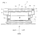
- Fig. 1 is a front view of the printer device 10
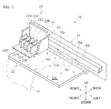
- Fig. 2 is a perspective view showing a portion near a head unit 20 that is described later.
- the printer device 10 includes a supporting frame 11 that consists of a left supporting leg 11a and a right supporting leg 11b, a central body 12 that is supported by the supporting frame 11, a left body 13 arranged on the left side of the central body 12, a right body 14 arranged on the right side of the central body 12, and an upper body 15 that is arranged above and parallel to the central body 12 with a gap therebetween, and extends across connecting the left body 13 and the right body 14.
- a platen 12a that extends across horizontally is provided in the central body 12 and is exposed to an upper surface thereof.
- a plurality of clamping units 15a is fixed to a lower portion of the upper body 15 and arranged in a horizontal direction.
- a pinch roller 15c is rotatably fixed to a front end portion of each of the clamping units 15a.
- a feed roller 12b that extends across horizontally and has a cylindrical shape is in contact with the platen 12a, and arranged beneath the pinch rollers 15c.
- the clamping units 15a can be set in a clamping position at which the pinch rollers 15c are in pressure contact with the feed roller 12b, and in an unclamping position at which the pinch rollers 15c are separated from the feed roller 12b.
- a printing sheet M that is a printing target after being sandwiched between the pinch rollers 15c and the feed roller 12b with the clamping units 15a set in the clamping position, can be moved forward or backward by a predetermined distance by causing the feed roller 12b to rotate.
- an operating unit 13a that includes operating switches, display panels, etc., is provided on a front surface of the left body 13.
- a controller 13b is provided inside the left body 13.
- the controller 13b outputs operation signals to structural components such as a fluid feed pump 17 and a suction pump 51 (see Fig. 3 ) of the printer device 10 that are described later and performs operation control.
- the controller 13b receives detection signals from an upper fluid level detecting sensor 43 and a lower fluid level detecting sensor 44 that are described later (see Figs. 5A to 5C ).
- An ink cartridge 16 that stores therein a predetermined amount of ink is attached to a back surface of the right body 14 so as to be attachable and detachable from behind.
- a configuration is illustrated in which four ink cartridges 16, each of which storing therein an aqueous ink of magenta (M), yellow (Y), cyan (C), and black (K) color, are mounted.
- a guide rail 15b that extends across horizontally is arranged inside the upper body 15 and the head unit 20 is fixed such that it can reciprocate horizontally along the guide rail 15b.
- the head unit 20 primarily includes a carriage 21, a printer head 22, and a sub-tank 23.
- a back surface of the carriage 21 is fitted to the guide rail 15b; therefore, the carriage 21 can reciprocate horizontally along the guide rail 15b.
- the carriage 21 serves as a base for mounting the printer head 22 and the sub-tank 23.
- the printer head 22 includes, for example, printer heads 22M, 22Y, 22C, and 22K of magenta, yellow, cyan, and black color, respectively.
- a plurality of discharge nozzles are provided, respectively, on bottom surfaces of the printer heads 22M, 22Y, 22C, and 22K for discharging the ink in a downward direction.
- the sub-tank 23 includes sub-tanks 23M, 23Y, 23C, and 23K that correspond to the four colors mentioned above. Each of the sub-tanks 23M, 23Y, 23C, and 23K stores therein a predetermined amount of ink. Detailed structure is described later.
- Each of the sub-tanks 23M, 23Y, 23C, and 23K is arranged above the corresponding printer heads 22M, 22Y, 22C, and 22K and is connected to the corresponding printer heads 22M, 22Y, 22C, and 22K such that the ink stored therein can be supplied to the corresponding printer heads 22M, 22Y, 22C, and 22K.
- a configuration of the sub-tank 23 is explained in detail below with reference to Figs. 3 to 6B .
- Fig. 3 is a schematic diagram of an ink supply circuit 60 that is described later.
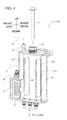
- Fig. 4 is a perspective view of the sub-tank 23.
- Figs. 5A to 5C are schematic diagrams of a fluid level detecting unit 40 that is described later, and
- Figs. 6A and 6B are illustrative diagrams of an operation of the fluid level detecting unit 40.
- Figs. 3 and 4 illustrate the ink supply circuit 60 of magenta color that includes the printer head 22M and the sub-tank 23M corresponding to the printer head 22M.
- the ink supply circuit 60 of magenta color is explained below as an example.
- the configuration of ink supply circuit 60 holds true for the other colors.
- the ink supply circuit 60 mainly includes an ink supply path 19, a decompression path 59, and the sub-tank 23M.
- the ink is supplied from the sub-tank 23M to the printer head 22M due to the hydraulic head difference.
- the fluid feed pump 17 is a pump that sucks the ink from the ink cartridge 16 and pressure-feeds it into the sub-tank 23M, and can, for example, be a tube pump or a diaphragm pump.
- the ink in the ink cartridge 16 can be supplied from the ink supply port 34 to inside of the sub-tank 23M.
- An end of the decompression path 59 is connected to a suction port 35 of the sub-tank 23M.
- a suction pump 51 and a flow regulating valve 52 are arranged in the decompression path 59.
- An air suction port (not shown) of the suction pump 51 is connected to the decompression path 59; therefore, the flow regulating valve 52 can regulate an amount of air that passes through the decompression path 59.
- an internal pressure of the sub-tank 23M can be set to a predetermined negative pressure that is suitable for formation of a meniscus in the discharge nozzles by sucking the air from inside of the sub-tank 23 according to an amount of air regulated with the flow regulating valve 52.
- the sub-tank 23M mainly includes a tank body 30 with an ink reservoir chamber 31 formed therein, a filter 38 fixed to the ink reservoir chamber 31, and the fluid level detecting unit 40 inserted in the ink reservoir chamber 31.
- a transparent film (not shown) is adhered so as to cover an entire left side face of the sub-tank 23M.
- the tank body 30 is formed in a substantially rectangular parallelepiped shape using a resin material. The tank body 30 is left open towards left and a depressed portion is treated as the ink reservoir chamber 31. The predetermined amount of ink is stored in the ink reservoir chamber 31 during printing.
- a supporting rib 32 is arranged vertically towards left from a right bottom 30a and wave preventing ribs 33F and 33B that extend vertically are formed.
- the film is adhered not only to a left end face of the tank body 30 but also to a left end face of the supporting rib 32 and the wave preventing ribs 33F and 33B. Due to this, excessive bending of the film can be prevented from occurring when the internal pressure of the sub-tank 23M changes.
- the filter 38 that is formed in a substantially rectangular parallelepiped shape is inserted into the protruding portion of the tank body 30.
- the filter 38 is supported by the supporting rib 32 such that it does not move towards left and right sides. With this configuration, the ink supplied from the ink supply port 34 is led inside the filter 38. The ink is filtered while flowing from the left side face of the filter 38 and proceeds towards the ink reservoir chamber 31.
- the suction port 35 is provided on the front side of an upper surface of the tank body 30 and an installation opening 36 is provided at the center of the upper surface of the tank body 30.
- the fluid level detecting unit 40 is inserted into the installation opening 36.
- three ink discharge ports 37 that communicate with the ink reservoir chamber 31 are provided to the bottom of the tank body 30 and the ink is supplied to the printer head 22M from the ink discharge ports 37.
- the fluid level detecting unit 40 mainly includes a casing 41 made from, for example, a transparent or a semi-transparent fluorine resin in a substantially cylindrical shape, a substrate 42 that is arranged inside the casing 41, and the upper fluid level detecting sensor 43 and the lower fluid level detecting sensor 44, respectively, attached to predetermined upper and lower positions relative to the substrate 42.
- a prism 48 that includes a first reflective surface 41a and a second reflective surface 41b on an outer surface, and that has a substantially isosceles triangle shape in a cross-sectional view is formed at the bottom end from near the center of the casing 41. As shown in Figs.
- the lower fluid level detecting sensor 44 includes a light emitting element 44a and a light receiving element 44b that are mounted on the substrate 42 in a line.
- the upper fluid level detecting sensor 43 also has a similar configuration, and includes a light emitting element 43a and a light receiving element 43b. Because a light emitted from the light emitting element 43a (44a) is reflected by the first reflective surface 41a and the second reflective surface 41b and is received by the light receiving element 43b(44b), the structure of the upper fluid level detecting sensor 43 and the lower fluid level detecting sensor 44 can be made compact.
- the configuration of the printer device 10 is explained hitherto. An operation of each component when performing printing on the printing sheet M using the printer device 10 is explained below.
- the printing sheet M that is wound in a roll is dispatched during printing and fed onto the platen 12a as shown in Fig. 2 .
- the ink is discharged in a downward direction from the discharge nozzles provided on the bottom surface of the printer head 22 while the carriage 21 is reciprocating horizontally along the guide rail 15b relative to the printing sheet M placed on the platen 12a and printing is performed by adhering the ink in a predetermined pattern.
- the ink is adhered to the printing sheet M while causing the carriage 21 to reciprocate again horizontally.
- the printing sheet M on which the printing is performed is wound in a roll on a front side of the printer device 10 by repeatedly performing the above operation.
- the ink is discharged from the printer head 22 and the ink equivalent to the discharged ink amount is automatically supplied from the sub-tank 23 to the printer head 22 due to the hydraulic head difference.
- the ink is supplied from the ink cartridge 16 to the sub-tank 23. Detection of the amount of ink in the sub-tank 23 and control of ink supply to the sub-tank 23 are explained below.
- the controller 13b detects that the ink fluid level is positioned between the upper fluid level detecting sensor 43 and the lower fluid level detecting sensor 44 and determines that the predetermined amount of ink is present in the ink reservoir chamber 31. Therefore, the fluid feed pump 17 is not driven and it is kept in a halted state.
- the ink fluid level rises to a position of the upper fluid level detecting sensor 43.
- the light is detected neither by the upper fluid level detecting sensor 43 nor by the lower fluid level detecting sensor 44, and as shown in Fig. 6B , nor by the light receiving elements 43b and 44b. Therefore, the controller 13b detects that the ink is stored up to a position of the upper fluid level detecting sensor 43 and determines that the ink fluid level has reached a maximum amount, and stops driving the fluid feed pump 17.
- the predetermined amount of ink can always be secured in the ink reservoir chamber 31 by controlling the driving of the fluid feed pump 17 based on the detection results of the ink fluid level in the ink reservoir chamber 31. Therefore, the printer head 22 can perform a stable ink discharge.
- a float is made to float on an ink fluid surface
- the ink fluid level is detected using an optical fluid level detecting unit 40. Because the optical fluid level detecting unit 40 does not have movable parts, the risk of damage can be minimized and the height of the fluid level can be detected in a highly precise and reliable manner.
- the wave preventing ribs 33F and 33B are formed in the tank body 30 so as to anteroposteriorly enclose the fluid level detecting unit 40 inserted vertically.
- the carriage 21 reciprocates horizontally during printing and the sub-tank 23 swings horizontally; however, due to the wave preventing ribs 33F and 33B, significant waving of the ink present inside the ink reservoir chamber 31 and changes in the fluid level can be prevented from occurring. Therefore, the height of the fluid level of the ink can be detected more precisely with the fluid level detecting unit 40.
- the casing 41 of the fluid level detecting unit 40 is made of fluorine resin having a high water repellency, the ink does not adhere to the casing 41 (first reflective surface 41a and second reflective surface 41b) and incorrect detection of the height of the ink fluid level using the fluid level detecting unit 40 can be reduced.
- the ink supply circuit 60 that supplies the ink from the ink cartridge 16 mounted on the back surface of the right body 14 to the sub-tank 23 is illustrated in the embodiment described above; however, the embodiment is not limited this configuration.
- an ink tank that stores therein an ink or an ink pack can be used in place of the ink cartridge 16.
- the ink cartridge 16 can be mounted below or above the right body 14.
- printing can be performed by mounting an ultraviolet radiation device on the carriage 21 and using an ultraviolet curing ink.
- the decompression path 59 is arranged in the ink supply circuit 60 and the air is set to a predetermined negative pressure by sucking it from inside the sub-tank 23.
- a pressurizing path that can be set to a predetermined positive pressure by supplying the air inside the sub-tank 23 can also be arranged.
- Such a configuration is effective for cleaning the ink reservoir chamber 31 of the sub-tank 23 by discharging the entire ink stored therein.
- the configuration of the upper fluid level detecting sensor 43, the lower fluid level detecting sensor 44, and the prism 48 is cited as an example in the embodiment described above; however, the present embodiment is not limited to this configuration.
- a prism that consists of only one reflective surface can be used and a light receiving element can be arranged at a position at which it can receive the light that is emitted from the light emitting element and is reflected by the reflective surface of the prism.
- the printer device 10 of a uniaxial printing medium moving type and a uniaxial printer head moving type is explained as an example of the printer device to which the present invention is applied.
- application of the present invention is not limited to this configuration.
- the present invention can be applied to, for example, a printer device of a biaxial printer head moving type or a printer device of a biaxial printing medium moving type.
Landscapes
- Ink Jet (AREA)
Abstract
Description
- The present invention relates to an ink supply device that is used in a printer device that performs printing by discharging an ink from a printer head.
- In printer devices (inkjet printers), printing is typically performed by adhering an ink to a printing medium, which is mounted on a platen, in a predetermined pattern by discharging the ink from discharge nozzles provided on a lower surface of a printer head while causing the printer head to move relative to the printing medium. In this printer device, if an internal pressure of the printer head becomes higher than atmospheric pressure, the ink is extruded from the discharge nozzles and dribbles onto the printing medium causing a so called dripping problem.
- As a method for solving this problem, providing a sub-tank that includes an ink chamber of a small capacity between a main tank, such as an ink cartridge, and the printer head and setting an internal pressure of the printer head to a marginally negative pressure by reducing a pressure within the ink chamber in the sub-tank is known in the art. For example, in
Fig. 1 of Patent Document 1, anink 12 stored in amain tank 14 is supplied to and temporarily stored in asub-tank 13 due to a hydraulic head difference and the ink is supplied to adischarge head 11 from thesub-tank 13 when an ink is discharge from thedischarge head 11. An internal pressure of thesub-tank 13 is maintained to a marginally negative pressure using a negativepressure generating unit 19. - In a method different from the method of supplying the ink to the sub-tank that uses the hydraulic head difference disclosed in Patent Document 1 described above, a supply pump is arranged in an ink supply path that connects a main tank and a sub-tank and the ink is supplied from the main tank to the sub-tank depending on an amount of ink in the sub-tank by causing the supply pump to drive. Though it is an advantage of this configuration that the
main tank 14 can be arranged at any position, there is also a disadvantage in that a detecting unit is required to detect the amount of ink (a height of the ink fluid level) in the sub-tank to control the driving of the supply pump. In view of this fact, for example, in Patent Document 2, a method is disclosed in which the height of the fluid level of fluid collected in any container, and not limited to the sub-tank, is detected using a magnetic force of a magnet 6 attached to a float 4. - [Patent Document 1] Japanese Unexamined Patent Application Laid-open No.
2006-62330 - [Patent Document 2] Japanese Unexamined Patent Application Laid-open No.
2001-141547 - Various types of inks with different physical properties, such as viscosity, are used for printing. Thus, when the height of the ink fluid level in the sub-tank is detected using a fluid level detection method disclosed in Patent Document 2, the height of the fluid level can be precisely detected by the float 4 to move vertically according to changes in the fluid level when a viscosity of the ink is low. However, the float 4 or the magnet 6 easily gets stuck to inner walls of the sub-tank when the viscosity of the ink is high. Thus, detection of the height of the fluid level is likely to become difficult.
- The present invention is made in view of the above problems and it is an object of the present invention to provide an ink supply device that includes a sub-tank in which a height of an ink fluid level can be precisely detected while maintaining an internal pressure of the sub-tank at a marginally negative pressure.
- To achieve the object, an ink supply device (for example, an
ink supply circuit 60 according to the embodiment) according to an aspect of the present invention is provided that is connected to a printer head that performs a desired printing by discharging a liquid ink and supplies the liquid ink to the printer head. The ink supply device includes a sub-tank that is connected to a printer head, and that has an ink reservoir chamber formed internally and that stores therein the liquid ink, and a fluid level detecting unit for detecting a height of a fluid level of the ink stored in the ink reservoir chamber attached in the ink reservoir chamber so as to extend vertically, an ink supply path that is formed by connecting a main tank that stores therein the liquid ink (for example, anink cartridge 16 according to the embodiment) and the ink reservoir chamber, and that supplies the liquid ink from the main tank to the ink reservoir chamber, an internal pressure regulating path (for example, adecompression path 59 according to the embodiment) that is formed by connecting a pressure regulating unit (for example, asuction pump 51 according to the embodiment) that can suck or discharge air and the ink reservoir chamber, and that regulates an internal pressure of the ink reservoir chamber, and a storage amount determining unit (for example, acontroller 13b according to the embodiment) that determines whether a predetermined amount of the liquid ink is stored in the ink reservoir chamber based on detection results of the fluid level detecting unit. The fluid level detecting unit includes a casing member (for example, acasing 41 according to the embodiment) in which is formed a section subjected to light projection (for example, aprism 48 according to the embodiment) that is adjacent to an outer surface with the liquid ink positioned according to an amount of the liquid ink stored in the ink reservoir chamber and which the light can enter, a light emitting unit (for example,light emitting elements light receiving elements - In the ink supply device, it is preferable that the fluid level detecting unit be configured such that when the fluid level of the ink stored in the ink reservoir chamber is positioned lower than a height of the section subjected to light projection at which the light from the light emitting unit has entered, the light is entirely reflected by the outer surface based on a refractive index difference between the section subjected to light projection and air and a light with a higher intensity than a predetermined intensity is received by the light receiving unit, and when the liquid ink is positioned at a level corresponding to the height of the section subjected to light projection at which the light has entered, the light is transmitted to the liquid ink side based on the refractive index difference between the section subjected to light projection and the liquid ink and a light having a lower intensity than the predetermined intensity is received.
- It is preferable that a pressure feed unit (for example, a
fluid feed pump 17 according to the embodiment) that pressure-feeds the liquid ink from a main tank to the ink reservoir chamber be arranged in the ink supply path, and the storage amount determining unit supply, upon determining an amount of the liquid ink stored in the ink reservoir chamber less than the predetermined amount, the liquid ink from the main tank to the ink reservoir chamber by causing the pressure feed unit to drive. - It is preferable that in the ink supply device, ribs (for example,
wave preventing ribs 33F and 33B according to the embodiment) that protrude inside the ink reservoir chamber be formed on either side of the fluid level detecting unit in the sub-tank. - It is preferable that a filter member (for example, a
filter 38 according to the embodiment) be arranged in a portion on the ink reservoir chamber side that connects with the ink supply path in the sub-tank. - An ink supply device according to an aspect of the present invention includes a sub-tank with a fluid level detecting unit attached thereto, an ink supply path, and an internal pressure regulating path. In the fluid level detecting unit, when a light emitted from a light emitting unit is reflected by a section subjected to light projection, it is received by a light receiving unit. Thus, whether a liquid ink has reached a height of the light emitting unit and the light receiving unit, and whether the light emitted from the light emitting unit is received by the light receiving unit can be detected using an optical method. Thus, because the fluid level detecting unit does not have movable parts, a situation such as sticking of a float to the walls is not likely to occur when compared with a configuration in which the float is made to float on an ink fluid surface and a height of the fluid level is detected with a magnetic force of a magnet. As a result, the height of the ink fluid level can be precisely detected while maintaining the ink reservoir chamber to a marginally negative pressure with an internal pressure regulating path.
- It is preferable that the fluid level detecting unit be configured such that when the liquid ink is not positioned in an outer surface of the section subjected to light projection, the light emitted from the light emitting unit is entirely reflected by the outer surface of the section subjected to light projection and the light is received by the light receiving unit. On the other hand, when the liquid ink is positioned in the outer surface of the section subjected to light projection, the light is transmitted towards the direction of the liquid ink without being reflected by the outer surface of the section subjected to light projection and it is seldom received by the light receiving unit. In this case, because the height of the ink fluid level can be detected by reflecting or transmitting the light emitted from the light emitting unit based on a refractive index difference, and the fluid level detecting unit does not have movable parts, the fluid level can be repeatedly detected with high precision.
- It is preferable that a pressure feed unit that pressure-feeds the liquid ink be arranged in the ink supply path and a storage amount determining unit cause, upon determining that a predetermined amount of the liquid ink is not stored, the pressure feed unit to drive for supplying the liquid ink to the ink reservoir chamber. With this configuration, the predetermined amount of the liquid ink is always stored in the ink reservoir chamber by controlling the driving of the pressure feed unit with the storage amount determining unit and the stored liquid ink can be supplied to a printer head without interruption. Due to this, the liquid ink can be stably discharged from the printer head.
- It is preferable that ribs be formed in the sub-tank on either side of the fluid level detecting unit attached to the sub-tank. With this configuration, the sub-tank performs traversal movement along with the printer head and swings during printing. Thus, even if the liquid ink inside the ink storage chamber waves, waving of the liquid ink (changes in the fluid level) can be restricted with these ribs. Thus, a height of the fluid level can be precisely detected with the fluid level detecting unit regardless of a traversal movement of the sub-tank.
- Furthermore, it is preferable that a filter be arranged in a portion on the ink storage chamber side that connects with the ink supply path. With this configuration, even if the liquid ink mixed with foreign particles such as dirt is supplied from the main tank, these particles are removed using a component that fits in an opening towards the ink reservoir chamber. Thus, the liquid ink inside the ink reservoir chamber and supplied to the printer head is free of any contaminants. As a result, the liquid ink can be discharged from the printer head without causing a discharge failure.
-
- [
Fig. 1] Fig. 1 is a front view of a printer device to which the present invention is applied. - [
Fig. 2] Fig. 2 is a perspective view that shows a portion near a head unit of the printer device shown inFig. 1 . - [
Fig. 3] Fig. 3 is a schematic diagram of an ink supply circuit of the printer device shown inFig. 1 . - [
Fig. 4] Fig. 4 is a perspective view of a sub-tank. - [
Figs. 5A to 5C] Figs. 5A to 5C are, respectively, a front view, a side view, and a bottom view of a fluid level detecting unit. - [
Figs. 6A and 6B] Figs. 6A and 6B are illustrative diagrams of operations of the fluid level detecting unit showing a state inFig. 6A in which the ink is not filled in a surrounding of the fluid level detecting unit and a state inFig. 6B in which the ink is filled in the surrounding of the fluid level detecting unit. -
- 13b
- Controller (Storage amount determining unit)
- 16
- Ink cartridge (Main tank)
- 17
- Fluid feed pump (Pressure feed unit)
- 19
- Ink supply path
- 22
- Printer head
- 23
- Sub-tank
- 31
- Ink reservoir chamber
- 33F and 33B
- Wave preventing rib (Rib)
- 38
- Filter (Filter member)
- 40
- Fluid level detecting unit
- 41
- Casing (Casing member)
- 43a, 44a
- Light emitting element (Light emitting unit)
- 43b, 44b
- Light receiving element (Light receiving unit)
- 48
- Prism (Section subjected to light projection)
- 51
- Suction pump (Pressure regulating unit)
- 59
- Decompression path (Inner pressure regulating path)
- 60
- Ink supply circuit (Ink supply device)
- Exemplary embodiments of the present invention are explained below with reference to the accompanying drawings. For the sake of simplicity, an explanation will be given with the help of arrow directions that are shown in the drawings and are defined as front-back, left-right, and up-down. An overall configuration of a
printer device 10 that is an example of an inkjet printer to which the present invention is applied, is explained with reference toFigs. 1 and2 .Fig. 1 is a front view of theprinter device 10 andFig. 2 is a perspective view showing a portion near ahead unit 20 that is described later. - As shown in
Fig. 1 , theprinter device 10 includes a supportingframe 11 that consists of a left supportingleg 11a and a right supporting leg 11b, acentral body 12 that is supported by the supportingframe 11, aleft body 13 arranged on the left side of thecentral body 12, aright body 14 arranged on the right side of thecentral body 12, and anupper body 15 that is arranged above and parallel to thecentral body 12 with a gap therebetween, and extends across connecting theleft body 13 and theright body 14. Aplaten 12a that extends across horizontally is provided in thecentral body 12 and is exposed to an upper surface thereof. - As shown in
Fig. 2 , a plurality of clampingunits 15a is fixed to a lower portion of theupper body 15 and arranged in a horizontal direction. Apinch roller 15c is rotatably fixed to a front end portion of each of the clampingunits 15a. A feed roller 12b that extends across horizontally and has a cylindrical shape is in contact with theplaten 12a, and arranged beneath thepinch rollers 15c. The clampingunits 15a can be set in a clamping position at which thepinch rollers 15c are in pressure contact with the feed roller 12b, and in an unclamping position at which thepinch rollers 15c are separated from the feed roller 12b. By this configuration, a printing sheet M that is a printing target, after being sandwiched between thepinch rollers 15c and the feed roller 12b with the clampingunits 15a set in the clamping position, can be moved forward or backward by a predetermined distance by causing the feed roller 12b to rotate. - As shown in
Fig. 1 , anoperating unit 13a that includes operating switches, display panels, etc., is provided on a front surface of theleft body 13. Moreover, acontroller 13b is provided inside theleft body 13. Thecontroller 13b outputs operation signals to structural components such as afluid feed pump 17 and a suction pump 51 (seeFig. 3 ) of theprinter device 10 that are described later and performs operation control. Moreover, thecontroller 13b receives detection signals from an upper fluidlevel detecting sensor 43 and a lower fluid level detecting sensor 44 that are described later (seeFigs. 5A to 5C ). Anink cartridge 16 that stores therein a predetermined amount of ink is attached to a back surface of theright body 14 so as to be attachable and detachable from behind. InFig. 1 , a configuration is illustrated in which fourink cartridges 16, each of which storing therein an aqueous ink of magenta (M), yellow (Y), cyan (C), and black (K) color, are mounted. - As shown in
Fig. 2 , aguide rail 15b that extends across horizontally is arranged inside theupper body 15 and thehead unit 20 is fixed such that it can reciprocate horizontally along theguide rail 15b. Thehead unit 20 primarily includes acarriage 21, aprinter head 22, and a sub-tank 23. A back surface of thecarriage 21 is fitted to theguide rail 15b; therefore, thecarriage 21 can reciprocate horizontally along theguide rail 15b. Furthermore, thecarriage 21 serves as a base for mounting theprinter head 22 and the sub-tank 23. - The
printer head 22 includes, for example, printer heads 22M, 22Y, 22C, and 22K of magenta, yellow, cyan, and black color, respectively. A plurality of discharge nozzles (not shown) are provided, respectively, on bottom surfaces of the printer heads 22M, 22Y, 22C, and 22K for discharging the ink in a downward direction. The sub-tank 23 includessub-tanks - A configuration of the sub-tank 23 is explained in detail below with reference to
Figs. 3 to 6B . -
Fig. 3 is a schematic diagram of anink supply circuit 60 that is described later.Fig. 4 is a perspective view of the sub-tank 23.Figs. 5A to 5C are schematic diagrams of a fluidlevel detecting unit 40 that is described later, andFigs. 6A and 6B are illustrative diagrams of an operation of the fluidlevel detecting unit 40.Figs. 3 and4 illustrate theink supply circuit 60 of magenta color that includes theprinter head 22M and the sub-tank 23M corresponding to theprinter head 22M. Theink supply circuit 60 of magenta color is explained below as an example. The configuration ofink supply circuit 60 holds true for the other colors. - As shown in
Fig. 3 , theink supply circuit 60 mainly includes anink supply path 19, adecompression path 59, and the sub-tank 23M. The ink is supplied from the sub-tank 23M to theprinter head 22M due to the hydraulic head difference. - An end of the
ink supply path 19 is connected to anink supply port 34 of the sub-tank 23M and theink cartridge 16 and thefluid feed pump 17 are arranged in theink supply path 19. Thefluid feed pump 17 is a pump that sucks the ink from theink cartridge 16 and pressure-feeds it into the sub-tank 23M, and can, for example, be a tube pump or a diaphragm pump. Thus, by driving thefluid feed pump 17, the ink in theink cartridge 16 can be supplied from theink supply port 34 to inside of the sub-tank 23M. - An end of the
decompression path 59 is connected to asuction port 35 of the sub-tank 23M. Asuction pump 51 and aflow regulating valve 52 are arranged in thedecompression path 59. An air suction port (not shown) of thesuction pump 51 is connected to thedecompression path 59; therefore, theflow regulating valve 52 can regulate an amount of air that passes through thedecompression path 59. Thus, by driving thesuction pump 51 during printing, an internal pressure of the sub-tank 23M can be set to a predetermined negative pressure that is suitable for formation of a meniscus in the discharge nozzles by sucking the air from inside of the sub-tank 23 according to an amount of air regulated with theflow regulating valve 52. - As shown in
Fig. 4 , the sub-tank 23M mainly includes atank body 30 with anink reservoir chamber 31 formed therein, afilter 38 fixed to theink reservoir chamber 31, and the fluidlevel detecting unit 40 inserted in theink reservoir chamber 31. A transparent film (not shown) is adhered so as to cover an entire left side face of the sub-tank 23M. Thetank body 30 is formed in a substantially rectangular parallelepiped shape using a resin material. Thetank body 30 is left open towards left and a depressed portion is treated as theink reservoir chamber 31. The predetermined amount of ink is stored in theink reservoir chamber 31 during printing. - In the
tank body 30, a supportingrib 32 is arranged vertically towards left from a right bottom 30a and wave preventingribs 33F and 33B that extend vertically are formed. The film is adhered not only to a left end face of thetank body 30 but also to a left end face of the supportingrib 32 and thewave preventing ribs 33F and 33B. Due to this, excessive bending of the film can be prevented from occurring when the internal pressure of the sub-tank 23M changes. - A lower portion of the
tank body 30 protrudes towards the front side and theink supply port 34 is fitted on an upper surface of this protruding portion. Thefilter 38 that is formed in a substantially rectangular parallelepiped shape is inserted into the protruding portion of thetank body 30. Thefilter 38 is supported by the supportingrib 32 such that it does not move towards left and right sides. With this configuration, the ink supplied from theink supply port 34 is led inside thefilter 38. The ink is filtered while flowing from the left side face of thefilter 38 and proceeds towards theink reservoir chamber 31. Due to this, fine dirt, etc., is removed from the ink, and a dirt-free ink can be stored in theink reservoir chamber 31, and supplied to theprinter head 22M enabling a stable ink discharge without any discharge failure, etc., at the discharge nozzles. - Furthermore, the
suction port 35 is provided on the front side of an upper surface of thetank body 30 and an installation opening 36 is provided at the center of the upper surface of thetank body 30. The fluidlevel detecting unit 40 is inserted into the installation opening 36. Furthermore, threeink discharge ports 37 that communicate with theink reservoir chamber 31 are provided to the bottom of thetank body 30 and the ink is supplied to theprinter head 22M from theink discharge ports 37. - As shown in
Figs. 5A to 5C , the fluidlevel detecting unit 40 mainly includes acasing 41 made from, for example, a transparent or a semi-transparent fluorine resin in a substantially cylindrical shape, asubstrate 42 that is arranged inside thecasing 41, and the upper fluidlevel detecting sensor 43 and the lower fluid level detecting sensor 44, respectively, attached to predetermined upper and lower positions relative to thesubstrate 42. Aprism 48 that includes a firstreflective surface 41a and a secondreflective surface 41b on an outer surface, and that has a substantially isosceles triangle shape in a cross-sectional view is formed at the bottom end from near the center of thecasing 41. As shown inFigs. 6A and 6B , the lower fluid level detecting sensor 44 includes alight emitting element 44a and alight receiving element 44b that are mounted on thesubstrate 42 in a line. The upper fluidlevel detecting sensor 43 also has a similar configuration, and includes alight emitting element 43a and alight receiving element 43b. Because a light emitted from thelight emitting element 43a (44a) is reflected by the firstreflective surface 41a and the secondreflective surface 41b and is received by thelight receiving element 43b(44b), the structure of the upper fluidlevel detecting sensor 43 and the lower fluid level detecting sensor 44 can be made compact. - The configuration of the
printer device 10 is explained hitherto. An operation of each component when performing printing on the printing sheet M using theprinter device 10 is explained below. - The printing sheet M that is wound in a roll is dispatched during printing and fed onto the
platen 12a as shown inFig. 2 . The ink is discharged in a downward direction from the discharge nozzles provided on the bottom surface of theprinter head 22 while thecarriage 21 is reciprocating horizontally along theguide rail 15b relative to the printing sheet M placed on theplaten 12a and printing is performed by adhering the ink in a predetermined pattern. After the printing sheet M is moved forward by a predetermined distance by causing the feed roller 12b to rotate, the ink is adhered to the printing sheet M while causing thecarriage 21 to reciprocate again horizontally. The printing sheet M on which the printing is performed is wound in a roll on a front side of theprinter device 10 by repeatedly performing the above operation. - When the printing is performed in this manner, the ink is discharged from the
printer head 22 and the ink equivalent to the discharged ink amount is automatically supplied from the sub-tank 23 to theprinter head 22 due to the hydraulic head difference. Thus, when it is detected that an amount of ink in the sub-tank 23 has gradually reduced and reached a predetermined minimum amount, the ink is supplied from theink cartridge 16 to the sub-tank 23. Detection of the amount of ink in the sub-tank 23 and control of ink supply to the sub-tank 23 are explained below. - A state in which the fluid level of the ink stored in the
ink reservoir chamber 31 is positioned between, for example, the upper fluidlevel detecting sensor 43 and the lower fluid level detecting sensor 44 is explained first. In this case, because the ink has not reached a level corresponding to a height of the upper fluidlevel detecting sensor 43, as shown inFig. 6A , the light emitted from thelight emitting element 43a of the upper fluidlevel detecting sensor 43 is entirely reflected by the firstreflective surface 41a and the secondreflective surface 41b based on a refractive index difference between theprism 48 and the air and this light is received by thelight receiving element 43b. On the other hand, as shown inFig. 6B , because the surrounding of the lower fluid level detecting sensor 44 is filled with the ink and the refractive index difference between theprism 48 and the ink has reduced, a major portion of the light emitted from thelight emitting element 44a of the lower fluid level detecting sensor 44 progresses in a direction where the ink exists (outward direction of the casing 41) without being entirely reflected by thefirst prism surface 41a towards thesecond prism surface 41b, and is not received by thelight receiving element 44b. When light reception results of thelight receiving elements controller 13b, thecontroller 13b detects that the ink fluid level is positioned between the upper fluidlevel detecting sensor 43 and the lower fluid level detecting sensor 44 and determines that the predetermined amount of ink is present in theink reservoir chamber 31. Therefore, thefluid feed pump 17 is not driven and it is kept in a halted state. - A case is now explained in which the fluid level of the ink being supplied to the
printer head 22 has gradually dropped to a position of the lower fluid level detecting sensor 44. In this case, along with the upper fluidlevel detecting sensor 43 and the lower fluid level detecting sensor 44, the light is also detected by thelight receiving elements Fig. 6A . From these detection results, thecontroller 13b detects that the ink fluid level has dropped to the position of the lower fluid level detecting sensor 44 and determines that the ink fluid level has reached the minimum amount. Therefore, thecontroller 13b causes thefluid feed pump 17 to be driven and the ink is supplied from theink cartridge 16 to theink reservoir chamber 31. - In a short while, due to the
fluid feed pump 17 being driven as described above, the ink fluid level rises to a position of the upper fluidlevel detecting sensor 43. When this happens, the light is detected neither by the upper fluidlevel detecting sensor 43 nor by the lower fluid level detecting sensor 44, and as shown inFig. 6B , nor by thelight receiving elements controller 13b detects that the ink is stored up to a position of the upper fluidlevel detecting sensor 43 and determines that the ink fluid level has reached a maximum amount, and stops driving thefluid feed pump 17. - As described above, the predetermined amount of ink can always be secured in the
ink reservoir chamber 31 by controlling the driving of thefluid feed pump 17 based on the detection results of the ink fluid level in theink reservoir chamber 31. Therefore, theprinter head 22 can perform a stable ink discharge. In a configuration in which a float is made to float on an ink fluid surface, for example, when the float gets stuck at the bottom position and cannot move vertically with changes in the fluid level, not only is the fluid level detected incorrectly but an amount of ink exceeding the maximum amount may be supplied to the sub-tank 23, thus leading to a risk of damage. On the other hand, in theprinter device 10 according to the present invention, the ink fluid level is detected using an optical fluidlevel detecting unit 40. Because the optical fluidlevel detecting unit 40 does not have movable parts, the risk of damage can be minimized and the height of the fluid level can be detected in a highly precise and reliable manner. - In the
printer device 10 according to the present invention, thewave preventing ribs 33F and 33B are formed in thetank body 30 so as to anteroposteriorly enclose the fluidlevel detecting unit 40 inserted vertically. Thecarriage 21 reciprocates horizontally during printing and the sub-tank 23 swings horizontally; however, due to thewave preventing ribs 33F and 33B, significant waving of the ink present inside theink reservoir chamber 31 and changes in the fluid level can be prevented from occurring. Therefore, the height of the fluid level of the ink can be detected more precisely with the fluidlevel detecting unit 40. Furthermore, in theprinter device 10 according to the present invention, because thecasing 41 of the fluidlevel detecting unit 40 is made of fluorine resin having a high water repellency, the ink does not adhere to the casing 41 (firstreflective surface 41a and secondreflective surface 41b) and incorrect detection of the height of the ink fluid level using the fluidlevel detecting unit 40 can be reduced. - The
ink supply circuit 60 that supplies the ink from theink cartridge 16 mounted on the back surface of theright body 14 to the sub-tank 23 is illustrated in the embodiment described above; however, the embodiment is not limited this configuration. For example, an ink tank that stores therein an ink or an ink pack can be used in place of theink cartridge 16. Furthermore, theink cartridge 16 can be mounted below or above theright body 14. - In the embodiment described above, a case in which an aqueous ink is used is explained as an example; however, various other types of inks can be used. For example, printing can be performed by mounting an ultraviolet radiation device on the
carriage 21 and using an ultraviolet curing ink. - In the embodiment described above, the
decompression path 59 is arranged in theink supply circuit 60 and the air is set to a predetermined negative pressure by sucking it from inside the sub-tank 23. However, in addition to this, a pressurizing path that can be set to a predetermined positive pressure by supplying the air inside the sub-tank 23 can also be arranged. Such a configuration is effective for cleaning theink reservoir chamber 31 of the sub-tank 23 by discharging the entire ink stored therein. - The configuration of the upper fluid
level detecting sensor 43, the lower fluid level detecting sensor 44, and theprism 48 is cited as an example in the embodiment described above; however, the present embodiment is not limited to this configuration. For example, a prism that consists of only one reflective surface can be used and a light receiving element can be arranged at a position at which it can receive the light that is emitted from the light emitting element and is reflected by the reflective surface of the prism. - In the embodiment described above, the
printer device 10 of a uniaxial printing medium moving type and a uniaxial printer head moving type is explained as an example of the printer device to which the present invention is applied. However, application of the present invention is not limited to this configuration. The present invention can be applied to, for example, a printer device of a biaxial printer head moving type or a printer device of a biaxial printing medium moving type.
Claims (5)
- An ink supply device that is connected to a printer head that performs a desired printing by discharging a liquid ink, and that supplies the liquid ink to the printer head, the ink supply device comprising:a sub tank that is connected to the printer head and that has an ink reservoir chamber formed internally and that can store the liquid ink, and a fluid level detecting unit that detects a height of the liquid ink stored in the ink reservoir chamber and is attached inside the ink reservoir chamber so as to extend vertically;an ink supply path that is formed by connecting a main tank that stores the liquid ink and the ink reservoir chamber, and that supplies the liquid ink from the main tank to the ink reservoir chamber;an internal pressure regulating path that is formed by connecting a pressure regulating unit that can suck or discharge air and the ink reservoir chamber, and that regulates an internal pressure of the ink reservoir chamber; anda storage amount determining unit that determines whether a predetermined amount of the liquid ink is stored in the ink reservoir chamber based on detection results of the fluid level detecting unit, whereinthe fluid level detecting unit includesa casing in which is formed a section subjected to light projection that is adjacent to an outer surface with the liquid ink positioned according to an amount of the liquid ink stored in the ink reservoir chamber and in which a light can enter,a light emitting unit that is arranged inside the casing and that emits the light from inside of the section subjected to light projection toward the section subjected to light projection, anda light receiving unit that is arranged at an entering position of the light emitted from the light emitting unit and reflected by the outer surface.
- The ink supply device according to Claim 1, wherein
the fluid level detecting unit is configured such that when the fluid level of the ink stored in the ink reservoir chamber is positioned lower than a height of the section subjected to light projection at which the light from the light emitting unit has entered, the light is entirely reflected by the outer surface based on a refractive index difference between the section subjected to light projection and the air and a light with a higher intensity than a predetermined intensity is received by the light receiving unit, and
when the liquid ink is positioned at a level corresponding to a height of the section subjected to light projection at which the light has entered, the light is transmitted to the liquid ink side based on the refractive index difference between the section subjected to light projection and the liquid ink and a light having a lower intensity than the predetermined intensity is received. - The ink supply device according to Claim 1 or 2, wherein
a pressure feed unit that pressure-feeds the liquid ink from the main tank to the ink reservoir chamber is arranged in the ink supply path, and
the storage amount determining unit causes, upon determining an amount of the liquid ink stored in the ink reservoir chamber less than the predetermined amount, the pressure feed unit to drive to supply the liquid ink from the main tank to the ink reservoir chamber. - The ink supply device according to any one of Claims 1 to 3, wherein ribs that protrude inside the ink reservoir chamber are formed on either side of the fluid level detecting unit in the sub-tank.
- The ink supply device according to any one of Claims 1 to 4, wherein the sub-tank includes a filter member arranged in a portion on the ink reservoir chamber side that connects with the ink supply path.
Applications Claiming Priority (1)
| Application Number | Priority Date | Filing Date | Title |
|---|---|---|---|
| PCT/JP2009/050254 WO2010079620A1 (en) | 2009-01-09 | 2009-01-09 | Ink supply circuit |
Publications (2)
| Publication Number | Publication Date |
|---|---|
| EP2325012A1 true EP2325012A1 (en) | 2011-05-25 |
| EP2325012A4 EP2325012A4 (en) | 2012-06-06 |
Family
ID=42316398
Family Applications (1)
| Application Number | Title | Priority Date | Filing Date |
|---|---|---|---|
| EP09837507A Withdrawn EP2325012A4 (en) | 2009-01-09 | 2009-01-09 | Ink supply circuit |
Country Status (6)
| Country | Link |
|---|---|
| US (1) | US20110221803A1 (en) |
| EP (1) | EP2325012A4 (en) |
| JP (1) | JPWO2010079620A1 (en) |
| KR (1) | KR101380274B1 (en) |
| CN (1) | CN102171047B (en) |
| WO (1) | WO2010079620A1 (en) |
Cited By (2)
| Publication number | Priority date | Publication date | Assignee | Title |
|---|---|---|---|---|
| EP3437881A1 (en) * | 2017-07-31 | 2019-02-06 | Brother Kogyo Kabushiki Kaisha | Image forming apparatus and image forming system |
| US10569564B2 (en) | 2016-12-28 | 2020-02-25 | Brother Kogyo Kabushiki Kaisha | Image forming apparatus including cartridge having first storage chamber and cartridge attachment portion having second storage chamber |
Families Citing this family (10)
| Publication number | Priority date | Publication date | Assignee | Title |
|---|---|---|---|---|
| JP5282746B2 (en) * | 2010-02-26 | 2013-09-04 | ブラザー工業株式会社 | Ink container |
| JP5645616B2 (en) * | 2010-11-17 | 2014-12-24 | キヤノン株式会社 | Recording device |
| JP2013107231A (en) * | 2011-11-18 | 2013-06-06 | Seiko Epson Corp | Liquid ejecting apparatus |
| CN103419496B (en) * | 2012-05-14 | 2015-12-23 | 珠海纳思达企业管理有限公司 | A kind of printer ink supply system and detection method thereof |
| KR101255723B1 (en) * | 2012-06-19 | 2013-04-17 | 장준용 | Ink supply apparatus |
| KR102614074B1 (en) * | 2016-12-05 | 2023-12-14 | 주식회사 탑 엔지니어링 | Inkjet type liquid dispensing module |
| CN109318590B (en) * | 2017-07-31 | 2021-06-04 | 兄弟工业株式会社 | Image recording apparatus |
| CN110271293A (en) * | 2018-03-16 | 2019-09-24 | 京瓷办公信息系统株式会社 | Ink supply unit, inkjet recording device and ink feed method |
| JPWO2024247087A1 (en) * | 2023-05-30 | 2024-12-05 | ||
| JP2025047183A (en) * | 2023-09-21 | 2025-04-03 | コニカミノルタ株式会社 | Ink level height measurement device and image formation device |
Family Cites Families (23)
| Publication number | Priority date | Publication date | Assignee | Title |
|---|---|---|---|---|
| US4857894A (en) * | 1988-06-27 | 1989-08-15 | The United States Of America As Represented By The Secretary Of The Navy | Liquid level measurement system for analog and digital readout |
| US5369429A (en) * | 1993-10-20 | 1994-11-29 | Lasermaster Corporation | Continuous ink refill system for disposable ink jet cartridges having a predetermined ink capacity |
| US6257712B1 (en) * | 1997-11-14 | 2001-07-10 | Brother Kogyo Kabushiki Kaisha | Ink feeder |
| GB9910313D0 (en) * | 1999-05-05 | 1999-06-30 | Cambridge Consultants | Fluid-pressure controlled ink pressure regulator |
| ATE461043T1 (en) * | 1999-11-05 | 2010-04-15 | Seiko Epson Corp | INK JET TYPE RECORDING APPARATUS AND METHOD FOR SUPPLYING INK TO THE SUB-TANK USING THE SAME APPARATUS AND METHOD FOR CONTROLLING THE AMOUNT OF INK SUPPLIED TO THE SUB-TANK USING THE SAME APPARATUS |
| JP2001141547A (en) | 1999-11-16 | 2001-05-25 | Toshiba Tec Corp | Liquid level detector |
| CN1799846B (en) * | 2000-01-21 | 2010-06-09 | 精工爱普生株式会社 | Ink cartridge for recording device and inkjet recording device |
| JP2001277535A (en) * | 2000-04-04 | 2001-10-09 | Seiko Epson Corp | Ink jet recording device |
| JP3809059B2 (en) * | 2000-10-13 | 2006-08-16 | 理想科学工業株式会社 | Ink supply device for multi-head printer |
| US6658933B2 (en) * | 2001-06-22 | 2003-12-09 | Clesse Industries | Fill-level indicator for a liquefied-petroleum-gas tank |
| JP2003300332A (en) * | 2002-04-10 | 2003-10-21 | Matsushita Electric Ind Co Ltd | Inkjet recording device |
| US7040729B2 (en) * | 2002-06-06 | 2006-05-09 | Oce Display Graphics Systems, Inc. | Systems, methods, and devices for controlling ink delivery to print heads |
| US6705711B1 (en) * | 2002-06-06 | 2004-03-16 | Oće Display Graphics Systems, Inc. | Methods, systems, and devices for controlling ink delivery to one or more print heads |
| EP1382946A1 (en) * | 2002-07-15 | 2004-01-21 | Product Innovation Limited | Level sensors |
| JP2004322412A (en) * | 2003-04-23 | 2004-11-18 | Konica Minolta Medical & Graphic Inc | Ink-jet printer |
| JP2005231351A (en) * | 2004-01-19 | 2005-09-02 | Fuji Photo Film Co Ltd | Inkjet recording apparatus |
| KR100788066B1 (en) * | 2004-06-03 | 2007-12-21 | 캐논 가부시끼가이샤 | An ink remaining amount detection module for ink jet recording, an ink tank including the ink remaining amount detection module, and an ink jet recording apparatus |
| JP4534245B2 (en) * | 2004-08-04 | 2010-09-01 | リコープリンティングシステムズ株式会社 | Inkjet printing device |
| JP2006062330A (en) | 2004-08-30 | 2006-03-09 | Sharp Corp | Discharge head device, fluid discharge device, and fluid discharge method |
| JP4623717B2 (en) * | 2004-12-10 | 2011-02-02 | キヤノンファインテック株式会社 | Ink supply apparatus and pressure generation method |
| JP2007237552A (en) * | 2006-03-08 | 2007-09-20 | Fuji Xerox Co Ltd | Liquid droplet discharge unit, and droplet discharge apparatus |
| JP4841463B2 (en) * | 2007-03-02 | 2011-12-21 | 富士フイルム株式会社 | Liquid ejection apparatus and recording apparatus |
| US7922312B2 (en) * | 2007-04-24 | 2011-04-12 | Hewlett-Packard Development Company, L.P. | Compact ink delivery in an ink pen |
-
2009
- 2009-01-09 JP JP2010545676A patent/JPWO2010079620A1/en active Pending
- 2009-01-09 EP EP09837507A patent/EP2325012A4/en not_active Withdrawn
- 2009-01-09 KR KR1020117006783A patent/KR101380274B1/en not_active Expired - Fee Related
- 2009-01-09 CN CN200980138983.2A patent/CN102171047B/en not_active Expired - Fee Related
- 2009-01-09 WO PCT/JP2009/050254 patent/WO2010079620A1/en not_active Ceased
-
2011
- 2011-03-30 US US13/075,191 patent/US20110221803A1/en not_active Abandoned
Cited By (2)
| Publication number | Priority date | Publication date | Assignee | Title |
|---|---|---|---|---|
| US10569564B2 (en) | 2016-12-28 | 2020-02-25 | Brother Kogyo Kabushiki Kaisha | Image forming apparatus including cartridge having first storage chamber and cartridge attachment portion having second storage chamber |
| EP3437881A1 (en) * | 2017-07-31 | 2019-02-06 | Brother Kogyo Kabushiki Kaisha | Image forming apparatus and image forming system |
Also Published As
| Publication number | Publication date |
|---|---|
| KR20110045084A (en) | 2011-05-03 |
| CN102171047A (en) | 2011-08-31 |
| WO2010079620A1 (en) | 2010-07-15 |
| JPWO2010079620A1 (en) | 2012-06-21 |
| KR101380274B1 (en) | 2014-04-02 |
| CN102171047B (en) | 2014-11-12 |
| EP2325012A4 (en) | 2012-06-06 |
| US20110221803A1 (en) | 2011-09-15 |
Similar Documents
| Publication | Publication Date | Title |
|---|---|---|
| US20110221803A1 (en) | Ink supply apparatus | |
| US8104855B2 (en) | Inkjet printer system and ink supply apparatus | |
| US8506060B2 (en) | Ink supply device for inkjet printer and inkjet printer | |
| JP5394773B2 (en) | Image forming apparatus | |
| US8142003B2 (en) | Inkjet printer system and ink supply apparatus | |
| US8047640B2 (en) | Inkjet printer system and ink supply apparatus | |
| JP2008290451A (en) | Recording apparatus and ink remaining amount detection method | |
| US8991971B2 (en) | Liquid ejecting apparatus | |
| US7658481B2 (en) | Droplet discharge apparatus | |
| JP2011207131A (en) | Liquid droplet injection apparatus | |
| JP4882243B2 (en) | Liquid supply device and liquid ejection device | |
| JP7138725B2 (en) | Inkjet printer and ink supply device | |
| US8186802B2 (en) | Liquid ejection devices | |
| JP2022126764A (en) | image recorder | |
| JP2018103568A (en) | Image recording device | |
| CN109318590B (en) | Image recording apparatus | |
| JP2020093438A (en) | Ink supply system and inkjet printer | |
| JP3305132B2 (en) | Method and apparatus for detecting remaining amount of ink in ink jet recording apparatus | |
| US10618304B2 (en) | Liquid discharge device and liquid discharge apparatus | |
| KR20090110773A (en) | Ink supply printer and inkjet printer equipped with the ink supply | |
| CN109318597B (en) | Image recording apparatus | |
| JP4923932B2 (en) | Detection device | |
| JP2007216628A (en) | Liquid ejector | |
| JP2023017622A (en) | Liquid discharging device and liquid storage container | |
| JP2016083834A (en) | Liquid injection device |
Legal Events
| Date | Code | Title | Description |
|---|---|---|---|
| PUAI | Public reference made under article 153(3) epc to a published international application that has entered the european phase |
Free format text: ORIGINAL CODE: 0009012 |
|
| 17P | Request for examination filed |
Effective date: 20110303 |
|
| AK | Designated contracting states |
Kind code of ref document: A1 Designated state(s): AT BE BG CH CY CZ DE DK EE ES FI FR GB GR HR HU IE IS IT LI LT LU LV MC MK MT NL NO PL PT RO SE SI SK TR |
|
| AX | Request for extension of the european patent |
Extension state: AL BA RS |
|
| DAX | Request for extension of the european patent (deleted) | ||
| A4 | Supplementary search report drawn up and despatched |
Effective date: 20120507 |
|
| RIC1 | Information provided on ipc code assigned before grant |
Ipc: B41J 2/175 20060101AFI20120427BHEP |
|
| STAA | Information on the status of an ep patent application or granted ep patent |
Free format text: STATUS: THE APPLICATION HAS BEEN WITHDRAWN |
|
| 18W | Application withdrawn |
Effective date: 20120814 |