EP2324996A1 - Segmented tire mold - Google Patents
Segmented tire mold Download PDFInfo
- Publication number
- EP2324996A1 EP2324996A1 EP10191001A EP10191001A EP2324996A1 EP 2324996 A1 EP2324996 A1 EP 2324996A1 EP 10191001 A EP10191001 A EP 10191001A EP 10191001 A EP10191001 A EP 10191001A EP 2324996 A1 EP2324996 A1 EP 2324996A1
- Authority
- EP
- European Patent Office
- Prior art keywords
- mold
- ring
- tire
- lifting
- segments
- Prior art date
- Legal status (The legal status is an assumption and is not a legal conclusion. Google has not performed a legal analysis and makes no representation as to the accuracy of the status listed.)
- Granted
Links
Images




Classifications
-
- B—PERFORMING OPERATIONS; TRANSPORTING
- B29—WORKING OF PLASTICS; WORKING OF SUBSTANCES IN A PLASTIC STATE IN GENERAL
- B29D—PRODUCING PARTICULAR ARTICLES FROM PLASTICS OR FROM SUBSTANCES IN A PLASTIC STATE
- B29D30/00—Producing pneumatic or solid tyres or parts thereof
- B29D30/06—Pneumatic tyres or parts thereof (e.g. produced by casting, moulding, compression moulding, injection moulding, centrifugal casting)
- B29D30/0601—Vulcanising tyres; Vulcanising presses for tyres
- B29D30/0606—Vulcanising moulds not integral with vulcanising presses
- B29D30/0629—Vulcanising moulds not integral with vulcanising presses with radially movable sectors
-
- B—PERFORMING OPERATIONS; TRANSPORTING
- B29—WORKING OF PLASTICS; WORKING OF SUBSTANCES IN A PLASTIC STATE IN GENERAL
- B29D—PRODUCING PARTICULAR ARTICLES FROM PLASTICS OR FROM SUBSTANCES IN A PLASTIC STATE
- B29D30/00—Producing pneumatic or solid tyres or parts thereof
- B29D30/06—Pneumatic tyres or parts thereof (e.g. produced by casting, moulding, compression moulding, injection moulding, centrifugal casting)
- B29D30/0601—Vulcanising tyres; Vulcanising presses for tyres
- B29D30/0605—Vulcanising presses characterised by moulds integral with the presses having radially movable sectors
Definitions
- the manufacturing of pneumatic tires for motor vehicles of nearly all sizes entails the steps of creating the carcass and attaching thereto the tread and sidewalls, which are made of uncured rubber.
- the combination of carcass, tread and sidewalls, prior to curing of the rubber, is called a 'green tire.
- the final step in the manufacture of a tire is the insertion of the green tire into a tire mold, wherein the tire is heated to a sufficiently high temperature to vulcanize the tire. The tire is then removed from the mold and the manufacturing process is complete.
- the invention is about a tire mold in accordance with claim 1.
- Axial refers to the direction that is parallel to the primary axis of a tire or a tire mold.
- Major Axis refers to the major cylindrical axis of a circular cylinder.
- Ring refers to the direction that is normal to the primary axis of a tire or to a tire mold.
- Figure 1 illustrates a cross-sectional side view of a tire mold 10 of the present invention shown in the closed position
- Figure 2 illustrates the mold in the open position
- the mold as shown has an upper portion 11 which includes a sidewall annular ring 18 having a central opening 14.
- the sidewall annular ring 18 may be further divided into two or more sidewall components 18a, 18b as shown, for ease of manufacturing.
- the sidewall components 18a, 18b each include an inner surface 17a, 17b for molding the sidewall of a tire.
- the upper mold portion 11 further includes an optional annular shoulder ring 20.
- the optional shoulder ring 20 is located between the sidewall components 18a, 18b and an annular actuating ring 24.
- the shoulder ring has an inner molding surface 21 for molding the shoulder/tread area of the tire.
- the annular actuating ring 24 comprises an inner frustroconical surface 25 aligned for engagement with an outer frustroconical surface 31 of the tread segments, and functions to align the tread segments during closing of the mold.
- two or more alignment cylinders 26 mounted on the exterior surface of the annular actuating ring.
- the alignment pins 27 together with the alignment cylinders ensure proper alignment of the upper portion of the mold with the lower portion of the mold.
- a lower portion 12 of the mold 10 includes a lower sidewall ring 34 having a central opening 33.
- the lower sidewall ring may be further subdivided into two or more components 34a, 34b.
- An optional shoulder ring 36 is positioned radially outward of the sidewall ring.
- the optional shoulder ring has a tread forming surface 35 for forming the shoulder section of the tire and an axially inward surface in engagement with an annular lifting ring 38.
- the annular lifting ring 38 is positioned between a bottom mold ring 52 and the lower sidewall ring components 34a, 34b.
- the annular lifting ring 38 is fixedly connected to the sidewall ring 34 and the optional shoulder ring 36.
- the annular lifting ring has a tabular end 2 that is received within a slot 3 of the bottom mold ring 52, wherein the tabular end of the annular lifting ring is in slidable engagement with the slot 3 of the bottom mold ring 52.
- the annular lifting ring further comprises an axially outer surface 39 for engagement with the tread segments.
- the axially outer surface 39 may further include an optional wear plate.
- the lower portion of the mold further comprises a plurality of tread segments 32, which are arranged circumferentially about the green tire to be molded.
- Each tread segment 32 has a tread molding surface having for example, lands and grooves for molding the tread of a green tire.
- the tread segments join together to form an annular ring to encircle and mold a tread of a green tire.
- each tread segment is formed of a one piece unit and is not split into two or more pieces.
- each tread segment has a tread molding surface which extends substantially unbroken across the outer tread surface of the green tire, from one shoulder to the opposite shoulder.
- each tread segment further has an upper frustroconical surface 31 opposite the tread molding surface that is aligned for engagement with the conical surface 25 of the annular actuating ring 24.
- Each tread segment 32 further comprises a lower frustroconical surface 28 that is aligned for engagement with a frustroconical surface 53 of the bottom mold ring 52.
- the tread segment lower conical surface 28 further includes a groove 44 for receiving a guide member 45 therein.
- the guide member 45 is positioned on the inner frustroconical surface 53 of the bottom mold ring 52 and is slidable within the tread segment groove 44.
- one or more guide pins 43 are positioned on the inner frustroconical surface 53 of the bottom mold ring 52.
- Each guide pin 43 is received in a groove 72 located on the lower frustroconical surface 53 of the bottom mold ring 52 as shown in Figure 8 .
- the guide pins 43 act as a stop to prevent the segments from moving too far axially outward.
- the guide pins 43 may also have a tight tolerance with respect to tread segment groove 72 to ensure precise movement or translation of the segments during opening and closing of the molds.
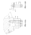
- Each tread segment further has an axially inner surface 47 that is slidable along the outer surface 39 of the bottom lifting ring 38. As shown in Figures 11A and 11B *, the tread segment axially inner surface 47 may further comprise optional guide fins 80 that are slidably received in slots 82 of the lower lifting ring 38.
- Each segment is actuatable in both a radial and an axial direction.
- each segment is actuated axially and radially by a lifting plate 50.
- the lower mold components including the lower sidewall ring 34a, 34b and the annular lifting ring 38 are positioned upon the lifting plate 50.
- the annular lifting ring 38 slides in an axial direction within the outer mold ring 52 and lifts the segments.
- the segment radially inner surface 47 slides radially outward along the surface 39 of the lifting ring.
- the lifting plate 50 lifts the tread segments, the segment lower frustroconical surface 28 slides into engagement with the cammed or frustroconical surface 53 of the bottom mold ring 52.
- the guide members of the mold bottom half slide within the groove 44 of the segment outer surface to ensure the segments slide axially and radially outwards.
- the optional guide fins 80 may be utilized to guide the segments as they are slid axially, and may further assist the movement of the tread segments during closing of the mold.
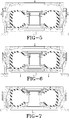
- Figures 3-7 illustrate the loading of a green tire into the mold.
- the lifting plate 50 is raised to its maximum vertical elevation relative to the lower actuating ring 52 as shown in Figure 3 .
- those parts of the lower mold portion 12 that are lifted by the lower actuating ring 52 namely the sidewall ring 34, the shoulder ring 36, the annular lifting ring 38 and the segments 32.
- the segments are positioned in an open position wherein they are disposed at their maximal radial displacement from one another. This position provides clearance for the insertion of a green tire.
- the lifting plate lowers the lower mold portion 12 to a point where the segments 32 almost make contact with the green tire as shown in Figures 4 - 6 .
- the upper mold portion 11 is lowered until the camming surface of the upper mold ring contacts the upper segment outer wall 31 ( Figure 6 ).
- the upper and lower mold portions are lowered by the lifting plate, as the upper mold ring guides the segment into position ( Figure 7 ).
- the mold opening can now be described in more detail.
- the upper part 11 of the mold 10 is hoisted or otherwise lifted vertically off of the tire (not shown) and the lower portion 12 of the mold.
- the tread segments 32 slide along the mold lower half to a lower and diametrically larger position within the conical section upper actuating ring 44, causing said segments to move radially apart from one another with respect to the main axis CL of the upper portion 32 of the tire mold 30.
- actuation of the lifting place 50 and the parts lifted by the lifting plate causes the tire to rise upward and the movable segments to move apart from one another and from the tire, thereby providing clearance for easy removal of the tire.
Landscapes
- Engineering & Computer Science (AREA)
- Mechanical Engineering (AREA)
- Moulds For Moulding Plastics Or The Like (AREA)
- Heating, Cooling, Or Curing Plastics Or The Like In General (AREA)
Abstract
Description
- The manufacturing of pneumatic tires for motor vehicles of nearly all sizes entails the steps of creating the carcass and attaching thereto the tread and sidewalls, which are made of uncured rubber. The combination of carcass, tread and sidewalls, prior to curing of the rubber, is called a 'green tire.' The final step in the manufacture of a tire is the insertion of the green tire into a tire mold, wherein the tire is heated to a sufficiently high temperature to vulcanize the tire. The tire is then removed from the mold and the manufacturing process is complete.
- Whereas the manufacturing of tires for automobiles, even large automobiles such as sport utility vehicles, is a straightforward process involving relatively lightweight green tires, the manufacture of large tires for industrial or large off-road type vehicles of the sort used in earth moving and construction work entails the handling of very large green tires weighing hundreds of pounds. The loading of such massive tires, in the green-tire stage of production, into the standard two-part tire molds having an upper portion and a lower portion can result in damage to the green tires during the loading process, because the diametrical and circumferential dimensions of the mold are so close to each green tire being loaded into the mold as to result in interference. Thus it is desired to have an improved tire mold which allows for ease of loading and unloading of the green tire into and out of the tire mold.
- The invention is about a tire mold in accordance with claim 1.
- Dependent claims refer to preferred embodiments of the invention.
- The structure, operation, and advantages of the present preferred embodiment of the invention will become further apparent upon consideration of the following description taken in conjunction with the accompanying FIGURES, wherein:
-
FIGURE 1 is a cross-sectional side view of a tire mold of the present invention shown in the closed position; -
FIGURE 2 is a cross-sectional side view of the tire mold ofFigure 1 shown in the open position; -
FIGURES 3 - 6 are cross-sectional side views of the tire mold ofFigure 1 , showing the sequence of a tire being loaded into the tire mold; and -
FIGURE 7 is a cross-sectional side view of the tire mold ofFigure 1 shown in the closed position. -
FIGURE 8 is a rear view of a mold segment; -
FIGURE 9 is a side view of a lower actuating ring; -
FIGURE 10A is an end view of an annular lifting ring; and -
FIGURE 10B is a side view of the annular lifting ring. -
FIGURE 11A is a side view of a bottom portion of a tread segment shown with an optional guide fin. -
FIGURE 11B is a front view of a bottom portion of a segment and an optional guide fin. - "Axial" refers to the direction that is parallel to the primary axis of a tire or a tire mold.
- "Major Axis" refers to the major cylindrical axis of a circular cylinder.
- "Radial" refers to the direction that is normal to the primary axis of a tire or to a tire mold.
-
Figure 1 illustrates a cross-sectional side view of atire mold 10 of the present invention shown in the closed position, whileFigure 2 illustrates the mold in the open position. The mold as shown has anupper portion 11 which includes a sidewallannular ring 18 having acentral opening 14. The sidewallannular ring 18 may be further divided into two ormore sidewall components sidewall components inner surface upper mold portion 11 further includes an optionalannular shoulder ring 20. Theoptional shoulder ring 20 is located between thesidewall components annular actuating ring 24. The shoulder ring has aninner molding surface 21 for molding the shoulder/tread area of the tire. Theannular actuating ring 24 comprises an innerfrustroconical surface 25 aligned for engagement with an outerfrustroconical surface 31 of the tread segments, and functions to align the tread segments during closing of the mold. - Mounted on the exterior surface of the annular actuating ring are two or
more alignment cylinders 26 positioned for receiving analignment pin 27 mounted on the outer circumference of the lower mold portion. Thealignment pins 27 together with the alignment cylinders ensure proper alignment of the upper portion of the mold with the lower portion of the mold. - Referring again to
Figure 1 , alower portion 12 of themold 10 includes a lower sidewall ring 34 having acentral opening 33. The lower sidewall ring may be further subdivided into two ormore components optional shoulder ring 36 is positioned radially outward of the sidewall ring. The optional shoulder ring has atread forming surface 35 for forming the shoulder section of the tire and an axially inward surface in engagement with anannular lifting ring 38. - The
annular lifting ring 38 is positioned between abottom mold ring 52 and the lowersidewall ring components annular lifting ring 38 is fixedly connected to the sidewall ring 34 and theoptional shoulder ring 36. As shown inFigures 10A and 10B , the annular lifting ring has atabular end 2 that is received within aslot 3 of thebottom mold ring 52, wherein the tabular end of the annular lifting ring is in slidable engagement with theslot 3 of thebottom mold ring 52. The annular lifting ring further comprises an axiallyouter surface 39 for engagement with the tread segments. The axiallyouter surface 39 may further include an optional wear plate. - The lower portion of the mold further comprises a plurality of
tread segments 32, which are arranged circumferentially about the green tire to be molded. Eachtread segment 32 has a tread molding surface having for example, lands and grooves for molding the tread of a green tire. The tread segments join together to form an annular ring to encircle and mold a tread of a green tire. Preferably, each tread segment is formed of a one piece unit and is not split into two or more pieces. Thus each tread segment has a tread molding surface which extends substantially unbroken across the outer tread surface of the green tire, from one shoulder to the opposite shoulder. As shown inFigure 8 , each tread segment further has an upperfrustroconical surface 31 opposite the tread molding surface that is aligned for engagement with theconical surface 25 of theannular actuating ring 24. Eachtread segment 32 further comprises a lowerfrustroconical surface 28 that is aligned for engagement with afrustroconical surface 53 of thebottom mold ring 52. The tread segment lowerconical surface 28 further includes agroove 44 for receiving aguide member 45 therein. As shown inFigure 9 , theguide member 45 is positioned on the innerfrustroconical surface 53 of thebottom mold ring 52 and is slidable within thetread segment groove 44. At other circumferential locations, one or more guide pins 43 are positioned on the innerfrustroconical surface 53 of thebottom mold ring 52. Each guide pin 43 is received in agroove 72 located on the lowerfrustroconical surface 53 of thebottom mold ring 52 as shown inFigure 8 . The guide pins 43 act as a stop to prevent the segments from moving too far axially outward. The guide pins 43 may also have a tight tolerance with respect totread segment groove 72 to ensure precise movement or translation of the segments during opening and closing of the molds. Each tread segment further has an axiallyinner surface 47 that is slidable along theouter surface 39 of thebottom lifting ring 38. As shown inFigures 11A and 11B *, the tread segment axiallyinner surface 47 may further compriseoptional guide fins 80 that are slidably received inslots 82 of thelower lifting ring 38. - Each segment is actuatable in both a radial and an axial direction. During the opening of the mold, each segment is actuated axially and radially by a
lifting plate 50. The lower mold components including thelower sidewall ring annular lifting ring 38 are positioned upon thelifting plate 50. As the lifting plate lifts thelifting ring 38 and the sidewall components 34, theannular lifting ring 38 slides in an axial direction within theouter mold ring 52 and lifts the segments. As the segments are lifted, the segment radiallyinner surface 47 slides radially outward along thesurface 39 of the lifting ring. As the liftingplate 50 lifts the tread segments, the segmentlower frustroconical surface 28 slides into engagement with the cammed orfrustroconical surface 53 of thebottom mold ring 52. - As the segments are lifted, the guide members of the mold bottom half slide within the
groove 44 of the segment outer surface to ensure the segments slide axially and radially outwards. Theoptional guide fins 80 may be utilized to guide the segments as they are slid axially, and may further assist the movement of the tread segments during closing of the mold. -
Figures 3-7 illustrate the loading of a green tire into the mold. As shown inFigure 2 , theupper portion 11 of the mold is removed. The liftingplate 50 is raised to its maximum vertical elevation relative to thelower actuating ring 52 as shown inFigure 3 . Also at maximum vertical elevation are those parts of thelower mold portion 12 that are lifted by thelower actuating ring 52, namely the sidewall ring 34, theshoulder ring 36, theannular lifting ring 38 and thesegments 32. At the maximum vertical elevation of the lifting plate, the segments are positioned in an open position wherein they are disposed at their maximal radial displacement from one another. This position provides clearance for the insertion of a green tire. - Once the green tire had been loaded into the
lower mold portion 12 as shown inFigure 4 , the lifting plate lowers thelower mold portion 12 to a point where thesegments 32 almost make contact with the green tire as shown inFigures 4 - 6 . Next theupper mold portion 11 is lowered until the camming surface of the upper mold ring contacts the upper segment outer wall 31 (Figure 6 ). Then the upper and lower mold portions are lowered by the lifting plate, as the upper mold ring guides the segment into position (Figure 7 ). When the mold 30 is fully closed and the top segments 42 and the bottom segments 43 are in their radially inward most locations (with respect to centerline CL), the upper dowels engage and lock with the lower dowels. - The mold opening can now be described in more detail. The
upper part 11 of themold 10 is hoisted or otherwise lifted vertically off of the tire (not shown) and thelower portion 12 of the mold. Upon lifting of the upper portion as shown inFigure 2 , thetread segments 32 slide along the mold lower half to a lower and diametrically larger position within the conical sectionupper actuating ring 44, causing said segments to move radially apart from one another with respect to the main axis CL of theupper portion 32 of the tire mold 30. - Upon removal of the upper portion of the tire mold 30, actuation of the lifting
place 50 and the parts lifted by the lifting plate causes the tire to rise upward and the movable segments to move apart from one another and from the tire, thereby providing clearance for easy removal of the tire. - Although the invention has been shown and described with respect to a certain preferred embodiment or embodiments, certain equivalent alterations and modifications will occur to others skilled in the art upon the reading and understanding of this specification and the annexed drawings. In particular regard to the various functions performed by the above described components (assemblies, devices, circuits, etc.), the terms (including a reference to a "means") used to describe such components are intended to correspond, unless otherwise indicated, to any component which performs the specified function of the described component (i.e., that is functionally equivalent), even though not structurally equivalent to the disclosed structure which performs the function in the herein illustrated exemplary embodiments of the invention. In addition, while a particular feature of the invention may have been disclosed with respect to only one of several embodiments, such feature may be combined with one or more features of the other embodiments as may be desired and advantageous for any given or particular application.
Claims (11)
- A tire mold comprising an upper mold portion (11) and a lower mold portion (12), wherein the upper mold portion (11) and the lower mold portion (12) are movable relative to one another for insertion of a tire into the mold (10), wherein the upper mold portion (11) includes an upper sidewall ring (18a, 18b) and an actuating ring (24) having an inner frustroconical surface (25), wherein the lower mold portion (12) includes a plurality of segments (32) each having an upper frustroconical surface (31) and a lower frustroconical surface (28), wherein the lower frustroconical surfaces (28) of the plurality of segments (32) are slidable against an inner frustoconical surface (53) of a bottom mold ring (52), a lifting plate (50), a lower sidewall ring (34, 34b), and a lifting ring (38) positioned between the bottom mold ring (52) and the lower sidewall ring (34a, 34b), wherein the lifting ring (38), the segments (32) and the lower sidewall ring (34a, 34b) are positioned on the lifting plate (50) for axial movement, and wherein the lifting ring (38) has a first end (2) slidable within a slot (3) of the bottom mold ring (52), and the lifting ring (38) has an axially outer surface (39) for engagement with the axially inner surface (47) of a segment (32).
- The mold of claim 1 wherein the bottom mold ring (52) has a plurality of guide members (45) positioned circumferentially on the inner frustroconical surface (53) of the bottom mold ring (52), and wherein each guide member (45) is positioned for reception in a respective groove (44) located on the lower frustroconical surface (28) of a respective segment (32).
- The mold of claim 1 or 2 wherein the bottom mold ring (52) comprises a plurality of guide pins (43) positioned circumferentially on the inner frustroconical surface (53) of the bottom mold ring (52), and wherein each guide pins (43) is positioned for reception in a respective groove (72) located on the lower frustroconical surface (28) of a respective segment (32).
- The mold of at least one of the previous claims wherein the lower sidewall ring (34a, 34b) and the lifting ring (38) are mounted on the lifting plate (50).
- The mold of at least one of the previous claims wherein the mold (10) is free of springs.
- The mold of at least one of the previous claims wherein the first end (2) is a tabular end (2) that is receivable within and, when received, in slidable engagement with the slot (3) of the bottom mold ring (52).
- The mold of at least one of the previous claims wherein the axially outer surface (39) of the lifting ring (38) comprises a wear plate.
- The mold of at least one of the previous claims wherein at least one or all of the segments (32) each comprise an axially inner surface (47) which comprises guide fine (80) which is slidably receivable in a respective slot (82) of the lower lifting ring (38).
- The mold of at least one of the previous claims wherein the mold (10) is an earth mover tire mold, a farm tire mold or a truck tire mold.
- The mold of at least one of the previous claims wherein the mold (10) is a tire mold for molding a tire which is to be mounted on an at least 508 mm (20 inch) rim.
- The mold of at least one of the previous claims wherein the mold (10) is a tire mold for molding a tire which is to be mounted on an at least 762 mm (30 inch) rim.
Applications Claiming Priority (1)
| Application Number | Priority Date | Filing Date | Title |
|---|---|---|---|
| US12/620,838 US7963756B2 (en) | 2009-11-18 | 2009-11-18 | Segmented tire mold |
Publications (2)
| Publication Number | Publication Date |
|---|---|
| EP2324996A1 true EP2324996A1 (en) | 2011-05-25 |
| EP2324996B1 EP2324996B1 (en) | 2012-09-26 |
Family
ID=43530933
Family Applications (1)
| Application Number | Title | Priority Date | Filing Date |
|---|---|---|---|
| EP10191001A Active EP2324996B1 (en) | 2009-11-18 | 2010-11-12 | Segmented tire mold |
Country Status (4)
| Country | Link |
|---|---|
| US (1) | US7963756B2 (en) |
| EP (1) | EP2324996B1 (en) |
| CN (1) | CN102069536B (en) |
| BR (1) | BRPI1004232A2 (en) |
Cited By (1)
| Publication number | Priority date | Publication date | Assignee | Title |
|---|---|---|---|---|
| WO2022073570A1 (en) * | 2020-10-05 | 2022-04-14 | Continental Reifen Deutschland Gmbh | Heating press and method for vulcanizing a vehicle tire in said heating press under vacuum |
Families Citing this family (12)
| Publication number | Priority date | Publication date | Assignee | Title |
|---|---|---|---|---|
| EP2881230B1 (en) * | 2013-11-27 | 2017-10-18 | The Goodyear Tire & Rubber Company | Ventless segmented tire mold |
| ITRM20130678A1 (en) * | 2013-12-09 | 2015-06-10 | Trelleborg Wheel Sys Italia Spa | MOLD WITH TWO HALF 'PROVIDED WITH SECTORS, FOR THE PRODUCTION OF TIRES BY VULCANIZATION. |
| US11318693B2 (en) | 2016-08-12 | 2022-05-03 | Toyo Tire Corporation | Tire vulcanization mold, tire vulcanization device, and tire production method |
| JP6605737B2 (en) * | 2016-08-12 | 2019-11-13 | Toyo Tire株式会社 | Tire vulcanizing apparatus and tire manufacturing method |
| WO2018029727A1 (en) * | 2016-08-12 | 2018-02-15 | 東洋ゴム工業株式会社 | Tire vulcanization mold, tire vulcanization device, and tire production method |
| CN107984780B (en) * | 2017-12-29 | 2020-04-17 | 山东豪迈机械科技股份有限公司 | Vacuumizing tire mold positioning mechanism and vacuumizing segmented mold |
| CN108297467B (en) * | 2018-01-02 | 2020-05-12 | 山东豪迈机械科技股份有限公司 | A tire flexible mold guide device, tire mold and tire |
| US10870248B2 (en) * | 2018-03-23 | 2020-12-22 | Bridgestone Americas Tire Operations, Llc | Non-symmetrical tread ring parting line mold |
| US11027506B1 (en) | 2020-06-12 | 2021-06-08 | The Goodyear Tire & Rubber Company | Actuating ring for tire mold assembly |
| DE102020212550A1 (en) * | 2020-10-05 | 2022-04-07 | Continental Reifen Deutschland Gmbh | Curing press and method for vulcanizing a vehicle tire in this curing press under vacuum |
| DE102020212548A1 (en) * | 2020-10-05 | 2022-04-07 | Continental Reifen Deutschland Gmbh | Curing press and method for vulcanizing a vehicle tire in this curing press under vacuum |
| DE102020212551A1 (en) * | 2020-10-05 | 2022-04-07 | Continental Reifen Deutschland Gmbh | Curing press and method for vulcanizing a vehicle tire in this curing press under vacuum |
Citations (6)
| Publication number | Priority date | Publication date | Assignee | Title |
|---|---|---|---|---|
| FR1440604A (en) * | 1963-02-06 | 1966-06-03 | Tire retreading machine | |
| US3505447A (en) * | 1966-06-01 | 1970-04-07 | Pneu Englebert Margnyles Compi | Segmental tire mold and method of molding an asymmetric tire |
| EP1038657A1 (en) * | 1999-03-26 | 2000-09-27 | PIRELLI PNEUMATICI S.p.A. | Method and apparatus for moulding and curing tyres for vehicle wheels |
| EP1649996A1 (en) * | 2003-07-25 | 2006-04-26 | Fuji Shoji Co., Ltd. | Tire vulcanizing method and vulcanizer for performing the method |
| FR2878780A1 (en) * | 2004-12-03 | 2006-06-09 | Goodyear Tire & Rubber | SEGMENT MOLD FOR PNEUMATIC BANDAGE FOR PNEUMATIC BANDAGES OF OFF-ROAD VEHICLES |
| EP1997600A1 (en) * | 2006-03-22 | 2008-12-03 | The Yokohama Rubber Co., Ltd. | Bisected mold for tire molding and process for manufacturing tire with use of the mold |
Family Cites Families (18)
| Publication number | Priority date | Publication date | Assignee | Title |
|---|---|---|---|---|
| NL279728A (en) * | 1961-07-07 | |||
| US3741696A (en) * | 1971-06-01 | 1973-06-26 | Goodyear Tire & Rubber | Segmented tire mold |
| US3730658A (en) * | 1971-06-25 | 1973-05-01 | Goodyear Tire & Rubber | Segmented tire mold |
| US3922122A (en) * | 1971-12-17 | 1975-11-25 | Pirelli | Apparatus for molding an embossed pattern on the peripheral band of a toroidal article, in particular on tire treads |
| DE2502185C3 (en) | 1975-01-21 | 1982-02-04 | Continental Gummi-Werke Ag, 3000 Hannover | Vulcanizing mold for pneumatic vehicle tires |
| US4022554A (en) | 1975-04-16 | 1977-05-10 | Macmillan Mold Company | Retread molds |
| KR940004796B1 (en) | 1989-02-15 | 1994-06-01 | 스미또모 고무 고오교오 가부시끼가이샤 | Mold for molding vulcanizatian |
| IT1248654B (en) * | 1990-05-29 | 1995-01-26 | Pirelli | VULCANIZATION PRESS WITH TWO MOLDS OPERATED SEPARATELY BETWEEN THEM PARTICULARLY FOR VEHICLE TIRES |
| FR2712229A1 (en) | 1993-11-12 | 1995-05-19 | Sedepro | Tire mold, and tire molding method. |
| US5676980A (en) | 1995-09-29 | 1997-10-14 | Continental General Tire, Inc. | Center split segmented mold for curing pneumatic tires |
| JP4191294B2 (en) | 1998-10-22 | 2008-12-03 | 株式会社ブリヂストン | Tire vulcanization mold and vulcanization molding method |
| JP2000135715A (en) | 1998-11-02 | 2000-05-16 | Bridgestone Corp | Tire vulcanization molding die and vulcanization molding method |
| ATE277750T1 (en) | 1999-12-13 | 2004-10-15 | Pirelli | OPTIMIZED DEVICE FOR VULCANIZING AIR TIRES AND DEVICE FOR IMPLEMENTING THE SAME |
| US6318985B1 (en) | 2000-09-15 | 2001-11-20 | Michelin Recherche Et Technique S.A. | Two-piece segmented mold |
| US6632393B2 (en) | 2001-09-06 | 2003-10-14 | Louis T. Fike | Method and apparatus for curing radial tires |
| JP4236413B2 (en) | 2002-02-15 | 2009-03-11 | 株式会社ブリヂストン | Tire vulcanizer |
| CN2889684Y (en) * | 2006-04-07 | 2007-04-18 | 宁新华 | Tire die |
| CN100396462C (en) * | 2006-10-18 | 2008-06-25 | 宁新华 | Tyre mould |
-
2009
- 2009-11-18 US US12/620,838 patent/US7963756B2/en active Active
-
2010
- 2010-11-09 BR BRPI1004232-6A patent/BRPI1004232A2/en not_active IP Right Cessation
- 2010-11-12 EP EP10191001A patent/EP2324996B1/en active Active
- 2010-11-18 CN CN2010105559254A patent/CN102069536B/en active Active
Patent Citations (6)
| Publication number | Priority date | Publication date | Assignee | Title |
|---|---|---|---|---|
| FR1440604A (en) * | 1963-02-06 | 1966-06-03 | Tire retreading machine | |
| US3505447A (en) * | 1966-06-01 | 1970-04-07 | Pneu Englebert Margnyles Compi | Segmental tire mold and method of molding an asymmetric tire |
| EP1038657A1 (en) * | 1999-03-26 | 2000-09-27 | PIRELLI PNEUMATICI S.p.A. | Method and apparatus for moulding and curing tyres for vehicle wheels |
| EP1649996A1 (en) * | 2003-07-25 | 2006-04-26 | Fuji Shoji Co., Ltd. | Tire vulcanizing method and vulcanizer for performing the method |
| FR2878780A1 (en) * | 2004-12-03 | 2006-06-09 | Goodyear Tire & Rubber | SEGMENT MOLD FOR PNEUMATIC BANDAGE FOR PNEUMATIC BANDAGES OF OFF-ROAD VEHICLES |
| EP1997600A1 (en) * | 2006-03-22 | 2008-12-03 | The Yokohama Rubber Co., Ltd. | Bisected mold for tire molding and process for manufacturing tire with use of the mold |
Cited By (3)
| Publication number | Priority date | Publication date | Assignee | Title |
|---|---|---|---|---|
| WO2022073570A1 (en) * | 2020-10-05 | 2022-04-14 | Continental Reifen Deutschland Gmbh | Heating press and method for vulcanizing a vehicle tire in said heating press under vacuum |
| CN116348277A (en) * | 2020-10-05 | 2023-06-27 | 大陆轮胎德国有限公司 | Hot press and method for vacuum vulcanizing vehicle tires in the hot press |
| US12246502B2 (en) | 2020-10-05 | 2025-03-11 | Continental Reifen Deutschland Gmbh | Heating press and method for vulcanizing a vehicle tire in said heating press under vacuum |
Also Published As
| Publication number | Publication date |
|---|---|
| US7963756B2 (en) | 2011-06-21 |
| BRPI1004232A2 (en) | 2013-02-19 |
| CN102069536A (en) | 2011-05-25 |
| EP2324996B1 (en) | 2012-09-26 |
| US20110117229A1 (en) | 2011-05-19 |
| CN102069536B (en) | 2013-11-20 |
Similar Documents
| Publication | Publication Date | Title |
|---|---|---|
| EP2324996B1 (en) | Segmented tire mold | |
| US10583584B2 (en) | Tire vulcanization mold, tire vulcanization device, and tire production method | |
| US7208061B2 (en) | Raw tire forming apparatus and raw tire forming method | |
| EP3670166B1 (en) | Tire clamping device, tire mold and method of molding a tire | |
| US20120027880A1 (en) | Method and apparatus for manufacturing tyres for vehicle wheels | |
| EP1935624A1 (en) | Three piece tire mold | |
| KR101539519B1 (en) | Tire vulcanization machine and tire vulcanization facility | |
| US8597008B1 (en) | Method and apparatus for controlling the sidewall vs. tread curing temperature in a tire mold | |
| US6808377B1 (en) | Segmented tire mold | |
| JP3810585B2 (en) | Tire vulcanizer | |
| CN117480042A (en) | Mold for forming tires and tire production method | |
| US6733259B2 (en) | Tire vulcanizing mold | |
| US8292606B2 (en) | Mold for tire with floating mold back ring | |
| US7661943B2 (en) | Mold for vulcanizing an unvulcanized tire blank | |
| JP2016016642A (en) | Method for manufacturing pneumatic tire | |
| US20060125147A1 (en) | Segmented tire mold for off-road-vehicle tires | |
| CN105324236B (en) | Tire-mold with improved durability | |
| EP0455126B1 (en) | Center mechanism for a tire vulcanizing machine | |
| CN206216982U (en) | Tire vulcanization mold | |
| JP2010099839A (en) | Tire vulcanizing apparatus and method for manufacturing vulcanized tire | |
| US20260061713A1 (en) | Curing mold and method for curing a green tire | |
| EP1222063B1 (en) | Segmented tire mold | |
| EP1106322A1 (en) | Vulcanizing mold for pneumatic tires | |
| WO2019039169A1 (en) | Heavy-duty tire vulcanization die, heavy-duty tire manufacturing method, and heavy-duty tire | |
| EP1105272A1 (en) | Spring spacer for bladder assembly in a tire curing press |
Legal Events
| Date | Code | Title | Description |
|---|---|---|---|
| PUAI | Public reference made under article 153(3) epc to a published international application that has entered the european phase |
Free format text: ORIGINAL CODE: 0009012 |
|
| AK | Designated contracting states |
Kind code of ref document: A1 Designated state(s): AL AT BE BG CH CY CZ DE DK EE ES FI FR GB GR HR HU IE IS IT LI LT LU LV MC MK MT NL NO PL PT RO RS SE SI SK SM TR |
|
| AX | Request for extension of the european patent |
Extension state: BA ME |
|
| 17P | Request for examination filed |
Effective date: 20111125 |
|
| RIC1 | Information provided on ipc code assigned before grant |
Ipc: B29C 33/02 20060101ALI20120308BHEP Ipc: B29D 30/06 20060101AFI20120308BHEP |
|
| GRAP | Despatch of communication of intention to grant a patent |
Free format text: ORIGINAL CODE: EPIDOSNIGR1 |
|
| GRAS | Grant fee paid |
Free format text: ORIGINAL CODE: EPIDOSNIGR3 |
|
| GRAA | (expected) grant |
Free format text: ORIGINAL CODE: 0009210 |
|
| AK | Designated contracting states |
Kind code of ref document: B1 Designated state(s): AL AT BE BG CH CY CZ DE DK EE ES FI FR GB GR HR HU IE IS IT LI LT LU LV MC MK MT NL NO PL PT RO RS SE SI SK SM TR |
|
| REG | Reference to a national code |
Ref country code: GB Ref legal event code: FG4D |
|
| REG | Reference to a national code |
Ref country code: CH Ref legal event code: EP |
|
| REG | Reference to a national code |
Ref country code: AT Ref legal event code: REF Ref document number: 576830 Country of ref document: AT Kind code of ref document: T Effective date: 20121015 |
|
| REG | Reference to a national code |
Ref country code: IE Ref legal event code: FG4D |
|
| REG | Reference to a national code |
Ref country code: DE Ref legal event code: R096 Ref document number: 602010002971 Country of ref document: DE Effective date: 20121122 |
|
| PG25 | Lapsed in a contracting state [announced via postgrant information from national office to epo] |
Ref country code: FI Free format text: LAPSE BECAUSE OF FAILURE TO SUBMIT A TRANSLATION OF THE DESCRIPTION OR TO PAY THE FEE WITHIN THE PRESCRIBED TIME-LIMIT Effective date: 20120926 Ref country code: NO Free format text: LAPSE BECAUSE OF FAILURE TO SUBMIT A TRANSLATION OF THE DESCRIPTION OR TO PAY THE FEE WITHIN THE PRESCRIBED TIME-LIMIT Effective date: 20121226 Ref country code: LT Free format text: LAPSE BECAUSE OF FAILURE TO SUBMIT A TRANSLATION OF THE DESCRIPTION OR TO PAY THE FEE WITHIN THE PRESCRIBED TIME-LIMIT Effective date: 20120926 Ref country code: HR Free format text: LAPSE BECAUSE OF FAILURE TO SUBMIT A TRANSLATION OF THE DESCRIPTION OR TO PAY THE FEE WITHIN THE PRESCRIBED TIME-LIMIT Effective date: 20120926 |
|
| REG | Reference to a national code |
Ref country code: AT Ref legal event code: MK05 Ref document number: 576830 Country of ref document: AT Kind code of ref document: T Effective date: 20120926 |
|
| REG | Reference to a national code |
Ref country code: LT Ref legal event code: MG4D Effective date: 20120926 |
|
| REG | Reference to a national code |
Ref country code: NL Ref legal event code: VDEP Effective date: 20120926 |
|
| PG25 | Lapsed in a contracting state [announced via postgrant information from national office to epo] |
Ref country code: SI Free format text: LAPSE BECAUSE OF FAILURE TO SUBMIT A TRANSLATION OF THE DESCRIPTION OR TO PAY THE FEE WITHIN THE PRESCRIBED TIME-LIMIT Effective date: 20120926 Ref country code: LV Free format text: LAPSE BECAUSE OF FAILURE TO SUBMIT A TRANSLATION OF THE DESCRIPTION OR TO PAY THE FEE WITHIN THE PRESCRIBED TIME-LIMIT Effective date: 20120926 Ref country code: GR Free format text: LAPSE BECAUSE OF FAILURE TO SUBMIT A TRANSLATION OF THE DESCRIPTION OR TO PAY THE FEE WITHIN THE PRESCRIBED TIME-LIMIT Effective date: 20121227 Ref country code: SE Free format text: LAPSE BECAUSE OF FAILURE TO SUBMIT A TRANSLATION OF THE DESCRIPTION OR TO PAY THE FEE WITHIN THE PRESCRIBED TIME-LIMIT Effective date: 20120926 |
|
| PG25 | Lapsed in a contracting state [announced via postgrant information from national office to epo] |
Ref country code: ES Free format text: LAPSE BECAUSE OF FAILURE TO SUBMIT A TRANSLATION OF THE DESCRIPTION OR TO PAY THE FEE WITHIN THE PRESCRIBED TIME-LIMIT Effective date: 20130106 Ref country code: CZ Free format text: LAPSE BECAUSE OF FAILURE TO SUBMIT A TRANSLATION OF THE DESCRIPTION OR TO PAY THE FEE WITHIN THE PRESCRIBED TIME-LIMIT Effective date: 20120926 Ref country code: NL Free format text: LAPSE BECAUSE OF FAILURE TO SUBMIT A TRANSLATION OF THE DESCRIPTION OR TO PAY THE FEE WITHIN THE PRESCRIBED TIME-LIMIT Effective date: 20120926 Ref country code: RO Free format text: LAPSE BECAUSE OF FAILURE TO SUBMIT A TRANSLATION OF THE DESCRIPTION OR TO PAY THE FEE WITHIN THE PRESCRIBED TIME-LIMIT Effective date: 20120926 Ref country code: BE Free format text: LAPSE BECAUSE OF FAILURE TO SUBMIT A TRANSLATION OF THE DESCRIPTION OR TO PAY THE FEE WITHIN THE PRESCRIBED TIME-LIMIT Effective date: 20120926 Ref country code: IS Free format text: LAPSE BECAUSE OF FAILURE TO SUBMIT A TRANSLATION OF THE DESCRIPTION OR TO PAY THE FEE WITHIN THE PRESCRIBED TIME-LIMIT Effective date: 20130126 Ref country code: EE Free format text: LAPSE BECAUSE OF FAILURE TO SUBMIT A TRANSLATION OF THE DESCRIPTION OR TO PAY THE FEE WITHIN THE PRESCRIBED TIME-LIMIT Effective date: 20120926 |
|
| PG25 | Lapsed in a contracting state [announced via postgrant information from national office to epo] |
Ref country code: PT Free format text: LAPSE BECAUSE OF FAILURE TO SUBMIT A TRANSLATION OF THE DESCRIPTION OR TO PAY THE FEE WITHIN THE PRESCRIBED TIME-LIMIT Effective date: 20130128 Ref country code: PL Free format text: LAPSE BECAUSE OF FAILURE TO SUBMIT A TRANSLATION OF THE DESCRIPTION OR TO PAY THE FEE WITHIN THE PRESCRIBED TIME-LIMIT Effective date: 20120926 Ref country code: SK Free format text: LAPSE BECAUSE OF FAILURE TO SUBMIT A TRANSLATION OF THE DESCRIPTION OR TO PAY THE FEE WITHIN THE PRESCRIBED TIME-LIMIT Effective date: 20120926 |
|
| PG25 | Lapsed in a contracting state [announced via postgrant information from national office to epo] |
Ref country code: AT Free format text: LAPSE BECAUSE OF FAILURE TO SUBMIT A TRANSLATION OF THE DESCRIPTION OR TO PAY THE FEE WITHIN THE PRESCRIBED TIME-LIMIT Effective date: 20120926 |
|
| PG25 | Lapsed in a contracting state [announced via postgrant information from national office to epo] |
Ref country code: BG Free format text: LAPSE BECAUSE OF FAILURE TO SUBMIT A TRANSLATION OF THE DESCRIPTION OR TO PAY THE FEE WITHIN THE PRESCRIBED TIME-LIMIT Effective date: 20121226 Ref country code: RS Free format text: LAPSE BECAUSE OF FAILURE TO SUBMIT A TRANSLATION OF THE DESCRIPTION OR TO PAY THE FEE WITHIN THE PRESCRIBED TIME-LIMIT Effective date: 20120926 Ref country code: DK Free format text: LAPSE BECAUSE OF FAILURE TO SUBMIT A TRANSLATION OF THE DESCRIPTION OR TO PAY THE FEE WITHIN THE PRESCRIBED TIME-LIMIT Effective date: 20120926 |
|
| PLBE | No opposition filed within time limit |
Free format text: ORIGINAL CODE: 0009261 |
|
| STAA | Information on the status of an ep patent application or granted ep patent |
Free format text: STATUS: NO OPPOSITION FILED WITHIN TIME LIMIT |
|
| REG | Reference to a national code |
Ref country code: IE Ref legal event code: MM4A |
|
| 26N | No opposition filed |
Effective date: 20130627 |
|
| REG | Reference to a national code |
Ref country code: DE Ref legal event code: R097 Ref document number: 602010002971 Country of ref document: DE Effective date: 20130627 |
|
| PG25 | Lapsed in a contracting state [announced via postgrant information from national office to epo] |
Ref country code: IE Free format text: LAPSE BECAUSE OF NON-PAYMENT OF DUE FEES Effective date: 20121112 |
|
| PG25 | Lapsed in a contracting state [announced via postgrant information from national office to epo] |
Ref country code: AL Free format text: LAPSE BECAUSE OF FAILURE TO SUBMIT A TRANSLATION OF THE DESCRIPTION OR TO PAY THE FEE WITHIN THE PRESCRIBED TIME-LIMIT Effective date: 20120926 Ref country code: CY Free format text: LAPSE BECAUSE OF FAILURE TO SUBMIT A TRANSLATION OF THE DESCRIPTION OR TO PAY THE FEE WITHIN THE PRESCRIBED TIME-LIMIT Effective date: 20120926 Ref country code: MT Free format text: LAPSE BECAUSE OF FAILURE TO SUBMIT A TRANSLATION OF THE DESCRIPTION OR TO PAY THE FEE WITHIN THE PRESCRIBED TIME-LIMIT Effective date: 20120926 |
|
| PG25 | Lapsed in a contracting state [announced via postgrant information from national office to epo] |
Ref country code: TR Free format text: LAPSE BECAUSE OF FAILURE TO SUBMIT A TRANSLATION OF THE DESCRIPTION OR TO PAY THE FEE WITHIN THE PRESCRIBED TIME-LIMIT Effective date: 20120926 Ref country code: MC Free format text: LAPSE BECAUSE OF NON-PAYMENT OF DUE FEES Effective date: 20121130 |
|
| PG25 | Lapsed in a contracting state [announced via postgrant information from national office to epo] |
Ref country code: SM Free format text: LAPSE BECAUSE OF FAILURE TO SUBMIT A TRANSLATION OF THE DESCRIPTION OR TO PAY THE FEE WITHIN THE PRESCRIBED TIME-LIMIT Effective date: 20120926 Ref country code: LU Free format text: LAPSE BECAUSE OF NON-PAYMENT OF DUE FEES Effective date: 20121112 |
|
| PG25 | Lapsed in a contracting state [announced via postgrant information from national office to epo] |
Ref country code: HU Free format text: LAPSE BECAUSE OF FAILURE TO SUBMIT A TRANSLATION OF THE DESCRIPTION OR TO PAY THE FEE WITHIN THE PRESCRIBED TIME-LIMIT Effective date: 20101112 |
|
| REG | Reference to a national code |
Ref country code: CH Ref legal event code: PL |
|
| GBPC | Gb: european patent ceased through non-payment of renewal fee |
Effective date: 20141112 |
|
| PG25 | Lapsed in a contracting state [announced via postgrant information from national office to epo] |
Ref country code: MK Free format text: LAPSE BECAUSE OF FAILURE TO SUBMIT A TRANSLATION OF THE DESCRIPTION OR TO PAY THE FEE WITHIN THE PRESCRIBED TIME-LIMIT Effective date: 20120926 Ref country code: LI Free format text: LAPSE BECAUSE OF NON-PAYMENT OF DUE FEES Effective date: 20141130 Ref country code: CH Free format text: LAPSE BECAUSE OF NON-PAYMENT OF DUE FEES Effective date: 20141130 |
|
| REG | Reference to a national code |
Ref country code: FR Ref legal event code: PLFP Year of fee payment: 6 |
|
| PG25 | Lapsed in a contracting state [announced via postgrant information from national office to epo] |
Ref country code: GB Free format text: LAPSE BECAUSE OF NON-PAYMENT OF DUE FEES Effective date: 20141112 |
|
| REG | Reference to a national code |
Ref country code: FR Ref legal event code: PLFP Year of fee payment: 7 |
|
| REG | Reference to a national code |
Ref country code: FR Ref legal event code: PLFP Year of fee payment: 8 |
|
| REG | Reference to a national code |
Ref country code: FR Ref legal event code: PLFP Year of fee payment: 9 |
|
| PGFP | Annual fee paid to national office [announced via postgrant information from national office to epo] |
Ref country code: IT Payment date: 20211012 Year of fee payment: 12 |
|
| PG25 | Lapsed in a contracting state [announced via postgrant information from national office to epo] |
Ref country code: IT Free format text: LAPSE BECAUSE OF NON-PAYMENT OF DUE FEES Effective date: 20221112 |
|
| REG | Reference to a national code |
Ref country code: DE Ref legal event code: R081 Ref document number: 602010002971 Country of ref document: DE Owner name: THE YOKOHAMA RUBBER CO., LTD., HIRATSUKA-SHI, JP Free format text: FORMER OWNER: THE GOODYEAR TIRE & RUBBER COMPANY, AKRON, OHIO, US |
|
| PGFP | Annual fee paid to national office [announced via postgrant information from national office to epo] |
Ref country code: DE Payment date: 20250930 Year of fee payment: 16 |
|
| PGFP | Annual fee paid to national office [announced via postgrant information from national office to epo] |
Ref country code: FR Payment date: 20251008 Year of fee payment: 16 |