EP2324951A1 - Double near-net forging of article - Google Patents
Double near-net forging of article Download PDFInfo
- Publication number
- EP2324951A1 EP2324951A1 EP10011137A EP10011137A EP2324951A1 EP 2324951 A1 EP2324951 A1 EP 2324951A1 EP 10011137 A EP10011137 A EP 10011137A EP 10011137 A EP10011137 A EP 10011137A EP 2324951 A1 EP2324951 A1 EP 2324951A1
- Authority
- EP
- European Patent Office
- Prior art keywords
- pressure side
- suction side
- width
- dividing portion
- forged part
- Prior art date
- Legal status (The legal status is an assumption and is not a legal conclusion. Google has not performed a legal analysis and makes no representation as to the accuracy of the status listed.)
- Withdrawn
Links
- 238000005242 forging Methods 0.000 title description 22
- 239000000463 material Substances 0.000 claims abstract description 26
- 238000000926 separation method Methods 0.000 claims abstract description 12
- 230000006378 damage Effects 0.000 claims abstract description 9
- 238000009792 diffusion process Methods 0.000 claims description 11
- RTAQQCXQSZGOHL-UHFFFAOYSA-N Titanium Chemical compound [Ti] RTAQQCXQSZGOHL-UHFFFAOYSA-N 0.000 claims description 9
- 238000005520 cutting process Methods 0.000 claims description 9
- 239000010936 titanium Substances 0.000 claims description 9
- 229910052719 titanium Inorganic materials 0.000 claims description 9
- 238000004519 manufacturing process Methods 0.000 claims description 3
- 238000000034 method Methods 0.000 description 17
- 238000003754 machining Methods 0.000 description 5
- 230000008569 process Effects 0.000 description 4
- 229910045601 alloy Inorganic materials 0.000 description 2
- 239000000956 alloy Substances 0.000 description 2
- 238000012986 modification Methods 0.000 description 2
- 230000004048 modification Effects 0.000 description 2
- 229910000831 Steel Inorganic materials 0.000 description 1
- 229910052782 aluminium Inorganic materials 0.000 description 1
- XAGFODPZIPBFFR-UHFFFAOYSA-N aluminium Chemical compound [Al] XAGFODPZIPBFFR-UHFFFAOYSA-N 0.000 description 1
- 230000015572 biosynthetic process Effects 0.000 description 1
- 238000010276 construction Methods 0.000 description 1
- 238000001816 cooling Methods 0.000 description 1
- 238000005553 drilling Methods 0.000 description 1
- 238000005516 engineering process Methods 0.000 description 1
- 230000001747 exhibiting effect Effects 0.000 description 1
- 238000005304 joining Methods 0.000 description 1
- 230000007246 mechanism Effects 0.000 description 1
- 229910052751 metal Inorganic materials 0.000 description 1
- 239000002184 metal Substances 0.000 description 1
- 239000007769 metal material Substances 0.000 description 1
- 150000002739 metals Chemical class 0.000 description 1
- 235000012771 pancakes Nutrition 0.000 description 1
- 230000009467 reduction Effects 0.000 description 1
- 239000010959 steel Substances 0.000 description 1
- XLYOFNOQVPJJNP-UHFFFAOYSA-N water Substances O XLYOFNOQVPJJNP-UHFFFAOYSA-N 0.000 description 1
- 238000003466 welding Methods 0.000 description 1
Images
Classifications
-
- B—PERFORMING OPERATIONS; TRANSPORTING
- B23—MACHINE TOOLS; METAL-WORKING NOT OTHERWISE PROVIDED FOR
- B23P—METAL-WORKING NOT OTHERWISE PROVIDED FOR; COMBINED OPERATIONS; UNIVERSAL MACHINE TOOLS
- B23P15/00—Making specific metal objects by operations not covered by a single other subclass or a group in this subclass
- B23P15/04—Making specific metal objects by operations not covered by a single other subclass or a group in this subclass turbine or like blades from several pieces
-
- Y—GENERAL TAGGING OF NEW TECHNOLOGICAL DEVELOPMENTS; GENERAL TAGGING OF CROSS-SECTIONAL TECHNOLOGIES SPANNING OVER SEVERAL SECTIONS OF THE IPC; TECHNICAL SUBJECTS COVERED BY FORMER USPC CROSS-REFERENCE ART COLLECTIONS [XRACs] AND DIGESTS
- Y10—TECHNICAL SUBJECTS COVERED BY FORMER USPC
- Y10T—TECHNICAL SUBJECTS COVERED BY FORMER US CLASSIFICATION
- Y10T29/00—Metal working
- Y10T29/49—Method of mechanical manufacture
- Y10T29/49316—Impeller making
- Y10T29/49336—Blade making
-
- Y—GENERAL TAGGING OF NEW TECHNOLOGICAL DEVELOPMENTS; GENERAL TAGGING OF CROSS-SECTIONAL TECHNOLOGIES SPANNING OVER SEVERAL SECTIONS OF THE IPC; TECHNICAL SUBJECTS COVERED BY FORMER USPC CROSS-REFERENCE ART COLLECTIONS [XRACs] AND DIGESTS
- Y10—TECHNICAL SUBJECTS COVERED BY FORMER USPC
- Y10T—TECHNICAL SUBJECTS COVERED BY FORMER US CLASSIFICATION
- Y10T29/00—Metal working
- Y10T29/49—Method of mechanical manufacture
- Y10T29/49316—Impeller making
- Y10T29/49336—Blade making
- Y10T29/49339—Hollow blade
Definitions
- the present invention relates to a method for forging articles requiring a single forging such as hollow fan blades for gas turbine engines.
- hollow fan blades typically fabricated from titanium, for use in gas turbine engines. It is preferable that such fan blades be hollow. By fabricating hollow fan blades, the mass of the fan blades may be substantially reduced resulting in notable efficiencies.
- the hollow fan blade halves are forged separately, one half corresponding to the pressure side with the other corresponding to the suction side. Once forged, each half is substantially machined to create the airfoil contour, the airfoil root block, datum features such as holes, hollow cavities, and diffusion bond surfaces. As noted this is done for both the pressure side and the suction side from each oversize "pancake" forging. The suction side and the pressure side are then subsequently diffusion bonded together to make a single hollow fan blade.
- a method of forming a blade comprises the steps of forging a part comprising a suction side, a pressure side, and a dividing portion of material greater than a portion of material to be sacrificed between the suction side and the pressure side, splitting the part through the dividing portion of material to form a suction side inner surface and a pressure side inner surface, and joining the suction side inner surface and the pressure side inner surface to form the blade.
- a forged part comprises a suction side, a pressure side, and a dividing portion of material between the suction side and the pressure side the dividing portion of a width greater than or equal to a separation destruction width.
- a method for forming a part comprises the steps of providing a mold, forging a part in the mold the part having a suction side, a pressure side, and a dividing portion of material between the suction side and the pressure side the dividing portion of a width greater than or equal to a separation destruction width.
- This is accomplished by forging a single part comprised of a pressure side and a suction side separated by a dividing portion of material.
- the dividing portion of material is only slightly larger than that which is needed to permit the suction side and the pressure side to be separated by a cutting operation. Once cut and separated, the suction side and the pressure side may be machined, particularly to include hollow cavities, then attached to one another through a process of diffusion bonding to produce a hollow part.
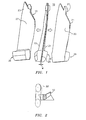
- Part 10 preferably utilized to create a fan blade, is comprised of a suction side 21 and a pressure side 23 separated by a dividing portion of material 25.
- the forging process is performed in a mold 62 ( FIG. 6 ) such that the outer surfaces of suction side 21 and pressure side 23 are of a shape requiring little or no post forging processing to achieve a finished exterior surface.
- the amount of material removed during post forging processing ranges on average from 0.030 inches to 0.125 inches (0.762 to 3.175 mm).
- the root block 29 and diffusion bond face feature 27 are forged in a substantially finished form suitable for machining so as to enable the bonding of the part 10 to a hub.
- the temperatures and pressures under which the forgings are performed vary depending on the desired mechanical properties of the finished part and are known in the art. Specifically, the temperatures and pressures for the forgings are selected to produce a finished part which exhibits desired tensile and compressive strengths as well as sufficient low and high cycle fatigue resistance.
- Root block 29 is formed of an amount of manufacturing material intended to be sacrificed during post-diffusion bonding machining. Specifically, root block 29 is not forged into a finished form, but, rather, is intended to be machined.
- root block 29 is constructed to allow for the part 10 to be gripped and friction welded to a hub or other receiving fixture. After friction welding part 10 to the hub, the remaining portion of root block 29 is machined off so as to leave a clean airfoil extending smoothly along the expanses formed by each of suction side 21 and pressure side 23.
- dividing portion of material 25 is of a width w. Width w is chosen depending upon the method by which pressure side 23 is to be separated from suction side 21. Preferably, pressure side 23 is separated from suction side 21 by cutting through and along dividing portion of material 25 with a band saw 32 as illustrated in FIG. 2 .
- Alternative methods include, but are not limited to, utilizing a water jet, or employing wire EDM. Each of the above-noted cutting methodologies results in a cut which destroys an approximately uniform width of material in the direction of the cut.
- the width, w, of the dividing portion of material 25 should be equal to, or preferably greater than, the separation destruction width of the cutting technology utilized.
- separation destruction width refers to the width of material which is sacrificed when employing a chosen methodology for cutting.
- the width, w, of dividing portion of material is approximately 10-20% wider than the separation destruction width.
- the dividing portion of the material 25 forms a generally planar expanse.
- all of the above identified methods of cutting dividing portion of the material 25 may be utilized to achieve a generally planar cut.
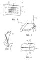
- FIG.4 there is illustrated a part 10 of the present invention wherein the dividing portion of the material 25 does not form a generally planar expanse. Rather, dividing portion 25 generally follows the twisting contours of both suction side 21 and pressure side 23. In such an instance, it is possible to program the operation of a wire EDM to alter its orientation as the cut along dividing portion 25 progresses so as to effectively remove dividing portion 25.
- part 10 is fabricated from titanium.
- part 10 may be formed of any metallic material exhibiting desired tensile and compressive strength as well as sufficient low and high cycle fatigue resistance.
- metallic material include, but are not limited to, titanium based alloys, forgeable alloys, aluminum, and steels.
- both suction side 21 and pressure side 23 post forging and post separation utilizing a cutting technique as described above.
- both suction side 21 and pressure side 23 possess an inner surface 33.
- Inner surface 33 is subsequently machined to contain at least one cavity 31 as illustrated with reference to FIG. 3 .
- each cavity formed into the inner surface 33 of suction side 21 has an associated, reciprocating cavity machined into the inner surface 33 of the opposing pressure side 23.
- reciprocating cavity it is meant that when suction side 21 and pressure side 23 are aligned and joined through the process of diffusion bonding, a cavity 31 located on the inner surface of suction side 21 is aligned with a cavity 31 fabricated into the inner surface 33 of pressure side 23 such that one continuous cavity is formed inside the bonded part 10.
- the fabrication of such cavities adds strength and resistance to deformation to the post-bonded part 10.
- the present invention is not so limited. Rather, the present invention encompasses any and all cavities, including cooling microcircuits, which may be fabricated into the inner surfaces of suction side 21 and pressure side 23.
- At least two alignment holes 51 are drilled or otherwise machined through both suction side 21 and pressure side 23 post forging and separation.
- the alignment holes 51 are used to precisely align the inner surfaces 33 of the suction side 21 and pressure side 23 for diffusion bonding. It is therefore important that the alignment holes are drilled in precisely the desired location.
- both the suction side 21 and the pressure side 23 in a six point trap 65 formed of at least six traps 61 and configured for use with either the suction side 21 or the pressure side 23.
- Each of the traps 61 restricts the part from movement in one of the six degrees of motion (three translational and three rotational).
- the part 10 is forged such that the exterior surfaces of both the suction side 21 and the pressure side 23 are in near finished condition (i.e. "near net"), they may each be placed in their respective six point traps 65 in a manner which precisely controls the orientation and placement of the sides 21, 23.
- a drilling mechanism 63 may then be positioned to precisely drill holes in the side 21, 23. As noted, these holes are then used to align the suction side 21 with the pressure side 23 for diffusion bonding to each other.
Landscapes
- Engineering & Computer Science (AREA)
- Mechanical Engineering (AREA)
- Forging (AREA)
- Structures Of Non-Positive Displacement Pumps (AREA)
Abstract
Description
- The present invention relates to a method for forging articles requiring a single forging such as hollow fan blades for gas turbine engines.
- It is current practice to fabricate hollow fan blades, typically fabricated from titanium, for use in gas turbine engines. It is preferable that such fan blades be hollow. By fabricating hollow fan blades, the mass of the fan blades may be substantially reduced resulting in notable efficiencies. Typically the hollow fan blade halves are forged separately, one half corresponding to the pressure side with the other corresponding to the suction side. Once forged, each half is substantially machined to create the airfoil contour, the airfoil root block, datum features such as holes, hollow cavities, and diffusion bond surfaces. As noted this is done for both the pressure side and the suction side from each oversize "pancake" forging. The suction side and the pressure side are then subsequently diffusion bonded together to make a single hollow fan blade.
- The use of diffusion bonding in turbine blade formation is well known. An example may be found in
U.S. patent 5,711,068 , the disclosure of which is incorporated by reference herein as if set forth at length. The '068 patent discloses a specific situation in which two blade halves are cut from a single piece and are diffusion bonded with uncut surfaces facing each other. - Such a process requires extensive machining time to achieve both the airfoil contour and the root block. In addition, a significant amount of scrap titanium is generated. What is therefore needed is a method for forging hollow fan blades, particularly titanium fan blades, which requires less machining and results in a reduction in the amount of scrap titanium generated.
- Accordingly, it is an object of the present invention to provide a method for forging articles requiring a single forging.
- In accordance with the present invention, a method of forming a blade comprises the steps of forging a part comprising a suction side, a pressure side, and a dividing portion of material greater than a portion of material to be sacrificed between the suction side and the pressure side, splitting the part through the dividing portion of material to form a suction side inner surface and a pressure side inner surface, and joining the suction side inner surface and the pressure side inner surface to form the blade.
- In further accordance with the present invention, a forged part comprises a suction side, a pressure side, and a dividing portion of material between the suction side and the pressure side the dividing portion of a width greater than or equal to a separation destruction width.
- In further accordance with the present invention, a method for forming a part comprises the steps of providing a mold, forging a part in the mold the part having a suction side, a pressure side, and a dividing portion of material between the suction side and the pressure side the dividing portion of a width greater than or equal to a separation destruction width.
-
-
FIG. 1 An illustration of the part of the present invention post forging and both pre and post separation. -
FIG. 2 An illustration of the part of the present invention and the cutting apparatus. -
FIG. 3 An illustration of the cavities fabricated in the inner surfaces of the present invention. -
FIG. 4 An illustration of the part of the present invention showing a non-planar dividing portion. -
FIG. 5 An illustration of the six point trap of the present invention. -
FIG. 6 An illustration of the mold of the present invention: - It is therefore a teaching of the present invention to provide a method for forging articles such as hollow fan blades, particularly titanium fan blades, requiring a minimum of post forging machining therefore significantly reducing the amount of scrap titanium generated. This is accomplished by forging a single part comprised of a pressure side and a suction side separated by a dividing portion of material. The dividing portion of material is only slightly larger than that which is needed to permit the suction side and the pressure side to be separated by a cutting operation. Once cut and separated, the suction side and the pressure side may be machined, particularly to include hollow cavities, then attached to one another through a process of diffusion bonding to produce a hollow part.
- With reference to
FIG. 1 , there is illustrated the construction of thepart 10.Part 10, preferably utilized to create a fan blade, is comprised of asuction side 21 and apressure side 23 separated by a dividing portion ofmaterial 25. - The forging process is performed in a mold 62 (
FIG. 6 ) such that the outer surfaces ofsuction side 21 andpressure side 23 are of a shape requiring little or no post forging processing to achieve a finished exterior surface. Typically, the amount of material removed during post forging processing ranges on average from 0.030 inches to 0.125 inches (0.762 to 3.175 mm). In particular, theroot block 29 and diffusionbond face feature 27 are forged in a substantially finished form suitable for machining so as to enable the bonding of thepart 10 to a hub. The temperatures and pressures under which the forgings are performed vary depending on the desired mechanical properties of the finished part and are known in the art. Specifically, the temperatures and pressures for the forgings are selected to produce a finished part which exhibits desired tensile and compressive strengths as well as sufficient low and high cycle fatigue resistance. -
Root block 29 is formed of an amount of manufacturing material intended to be sacrificed during post-diffusion bonding machining. Specifically,root block 29 is not forged into a finished form, but, rather, is intended to be machined. - In a preferred embodiment,
root block 29 is constructed to allow for thepart 10 to be gripped and friction welded to a hub or other receiving fixture. After friction weldingpart 10 to the hub, the remaining portion ofroot block 29 is machined off so as to leave a clean airfoil extending smoothly along the expanses formed by each ofsuction side 21 andpressure side 23. - As noted, located between
pressure side 23 andsuction side 21 is a dividing portion ofmaterial 25. As illustrated, dividing portion ofmaterial 25 is of a width w. Width w is chosen depending upon the method by whichpressure side 23 is to be separated fromsuction side 21. Preferably,pressure side 23 is separated fromsuction side 21 by cutting through and along dividing portion ofmaterial 25 with a band saw 32 as illustrated inFIG. 2 . Alternative methods include, but are not limited to, utilizing a water jet, or employing wire EDM. Each of the above-noted cutting methodologies results in a cut which destroys an approximately uniform width of material in the direction of the cut. As a result, the width, w, of the dividing portion ofmaterial 25 should be equal to, or preferably greater than, the separation destruction width of the cutting technology utilized. As used herein "separation destruction width" refers to the width of material which is sacrificed when employing a chosen methodology for cutting. In a preferred embodiment, the width, w, of dividing portion of material is approximately 10-20% wider than the separation destruction width. - In a preferred embodiment, the dividing portion of the
material 25 forms a generally planar expanse. In such an instance, all of the above identified methods of cutting dividing portion of thematerial 25 may be utilized to achieve a generally planar cut. With reference toFIG.4 , there is illustrated apart 10 of the present invention wherein the dividing portion of thematerial 25 does not form a generally planar expanse. Rather, dividingportion 25 generally follows the twisting contours of bothsuction side 21 andpressure side 23. In such an instance, it is possible to program the operation of a wire EDM to alter its orientation as the cut along dividingportion 25 progresses so as to effectively remove dividingportion 25. - Preferably,
part 10 is fabricated from titanium. - However,
part 10 may be formed of any metallic material exhibiting desired tensile and compressive strength as well as sufficient low and high cycle fatigue resistance. Such metals include, but are not limited to, titanium based alloys, forgeable alloys, aluminum, and steels. - With continued reference to
FIG. 1 , there is illustrated bothsuction side 21 andpressure side 23 post forging and post separation utilizing a cutting technique as described above. Once cut and separated, bothsuction side 21 andpressure side 23 possess aninner surface 33.Inner surface 33 is subsequently machined to contain at least onecavity 31 as illustrated with reference toFIG. 3 . Preferably, each cavity formed into theinner surface 33 ofsuction side 21 has an associated, reciprocating cavity machined into theinner surface 33 of the opposingpressure side 23. By reciprocating cavity, it is meant that whensuction side 21 andpressure side 23 are aligned and joined through the process of diffusion bonding, acavity 31 located on the inner surface ofsuction side 21 is aligned with acavity 31 fabricated into theinner surface 33 ofpressure side 23 such that one continuous cavity is formed inside the bondedpart 10. The fabrication of such cavities adds strength and resistance to deformation to thepost-bonded part 10. - While described with reference to reciprocating
cavities 31, the present invention is not so limited. Rather, the present invention encompasses any and all cavities, including cooling microcircuits, which may be fabricated into the inner surfaces ofsuction side 21 andpressure side 23. - With continued reference to
FIG. 3 , at least twoalignment holes 51 are drilled or otherwise machined through bothsuction side 21 andpressure side 23 post forging and separation. The alignment holes 51 are used to precisely align theinner surfaces 33 of thesuction side 21 andpressure side 23 for diffusion bonding. It is therefore important that the alignment holes are drilled in precisely the desired location. - It is therefore common practice to place the both the
suction side 21 and thepressure side 23 in a sixpoint trap 65 formed of at least sixtraps 61 and configured for use with either thesuction side 21 or thepressure side 23. Each of thetraps 61 restricts the part from movement in one of the six degrees of motion (three translational and three rotational). Because thepart 10 is forged such that the exterior surfaces of both thesuction side 21 and thepressure side 23 are in near finished condition (i.e. "near net"), they may each be placed in their respective sixpoint traps 65 in a manner which precisely controls the orientation and placement of thesides drilling mechanism 63 may then be positioned to precisely drill holes in theside suction side 21 with thepressure side 23 for diffusion bonding to each other. - It is apparent that there has been provided in accordance with the present invention a method for forging hollow blades requiring a single forging which fully satisfies the objects, means, and advantages set forth previously herein. While the present invention has been described in the context of specific embodiments thereof, other alternatives, modifications, and variations will become apparent to those skilled in the art having read the foregoing description. Accordingly, it is intended to embrace those alternatives, modifications, and variations as fall within the broad scope of the appended claims.
Claims (8)
- A forged part (10), comprising:a suction side (21);a pressure side (23); anda dividing portion (25) of material between said suction side (21) and said pressure side (23), wherein said dividing portion comprises a width greater than or equal to a separation destruction width,wherein said pressure side (23) and said suction side (21) are forged approximate to a finished exterior surface.
- The forged part of claim 1, wherein said separation destruction width is equal to a width of material sacrificed by a means for cutting.
- The forged part of claim 1 or 2, wherein said forged part (10) is comprised predominantly of titanium.
- The forged part of claim 1, 2 or 3, wherein said width of said dividing portion (25) of material is between approximately 10% and 20% greater than said separation destruction width.
- The forged part of any preceding claim, additionally comprising a root block (29) and at least one diffusion bond face feature (27).
- The forged part of any preceding claim, wherein said suction side (21) comprises the suction side of a fan blade.
- The forged part of any preceding claim, wherein said pressure side (23) comprises the pressure side of a fan blade.
- The forged part of any preceding claim, comprising:an airfoil section having a near-net shape; anda root section (29) having sacrificial material that is removed in a subsequent manufacturing step.
Applications Claiming Priority (2)
| Application Number | Priority Date | Filing Date | Title |
|---|---|---|---|
| US10/835,035 US7083388B2 (en) | 2004-04-29 | 2004-04-29 | Double near-net forging of article |
| EP05252704A EP1600251B1 (en) | 2004-04-29 | 2005-04-29 | Double near-net forging of article |
Related Parent Applications (1)
| Application Number | Title | Priority Date | Filing Date |
|---|---|---|---|
| EP05252704.1 Division | 2005-04-29 |
Publications (1)
| Publication Number | Publication Date |
|---|---|
| EP2324951A1 true EP2324951A1 (en) | 2011-05-25 |
Family
ID=34941121
Family Applications (2)
| Application Number | Title | Priority Date | Filing Date |
|---|---|---|---|
| EP05252704A Expired - Lifetime EP1600251B1 (en) | 2004-04-29 | 2005-04-29 | Double near-net forging of article |
| EP10011137A Withdrawn EP2324951A1 (en) | 2004-04-29 | 2005-04-29 | Double near-net forging of article |
Family Applications Before (1)
| Application Number | Title | Priority Date | Filing Date |
|---|---|---|---|
| EP05252704A Expired - Lifetime EP1600251B1 (en) | 2004-04-29 | 2005-04-29 | Double near-net forging of article |
Country Status (5)
| Country | Link |
|---|---|
| US (1) | US7083388B2 (en) |
| EP (2) | EP1600251B1 (en) |
| JP (1) | JP2005313321A (en) |
| AT (1) | ATE504389T1 (en) |
| DE (1) | DE602005027286D1 (en) |
Families Citing this family (10)
| Publication number | Priority date | Publication date | Assignee | Title |
|---|---|---|---|---|
| CN102037247B (en) * | 2008-03-28 | 2015-06-24 | 株式会社Ihi | Blade of a gas turbine engine for an airplane, and a method for manufacturing the same |
| JP5802972B2 (en) * | 2011-07-11 | 2015-11-04 | 大同特殊鋼株式会社 | Turbine blade manufacturing method |
| US9617860B2 (en) * | 2012-12-20 | 2017-04-11 | United Technologies Corporation | Fan blades for gas turbine engines with reduced stress concentration at leading edge |
| CA2897965C (en) | 2013-03-11 | 2020-02-25 | Rolls-Royce Corporation | Compliant intermediate component of a gas turbine engine |
| WO2015058043A1 (en) | 2013-10-18 | 2015-04-23 | United Technologies Corporation | Multiple piece engine component |
| US10309257B2 (en) | 2015-03-02 | 2019-06-04 | Rolls-Royce North American Technologies Inc. | Turbine assembly with load pads |
| DE102016224386A1 (en) * | 2016-12-07 | 2018-06-07 | MTU Aero Engines AG | METHOD FOR PRODUCING A SHOVEL FOR A FLOW MACHINE |
| CN108372391A (en) * | 2018-03-05 | 2018-08-07 | 广汉天空动力机械有限责任公司 | A kind of manufacturing method of turbine rotor hollow blade |
| US11009036B2 (en) * | 2018-08-30 | 2021-05-18 | Raytheon Technologies Corporation | Fan blade having closed metal sheath |
| CN112081775A (en) * | 2020-09-15 | 2020-12-15 | 中国航发沈阳发动机研究所 | Hollow blade and assembling method thereof |
Citations (5)
| Publication number | Priority date | Publication date | Assignee | Title |
|---|---|---|---|---|
| US4364160A (en) * | 1980-11-03 | 1982-12-21 | General Electric Company | Method of fabricating a hollow article |
| US5711068A (en) | 1995-10-28 | 1998-01-27 | Rolls-Royce Plc | Method of manufacturing a blade |
| EP1338353A1 (en) * | 2002-02-20 | 2003-08-27 | Rolls-Royce Plc | A method of manufacturing an article by diffusion bonding and superplastic forming |
| US20040040361A1 (en) * | 2002-09-02 | 2004-03-04 | Heinz-Rudolf Jung | Method of producing bladed components, blanks for bladed components, and use of the blanks |
| US6705011B1 (en) * | 2003-02-10 | 2004-03-16 | United Technologies Corporation | Turbine element manufacture |
Family Cites Families (4)
| Publication number | Priority date | Publication date | Assignee | Title |
|---|---|---|---|---|
| US3628226A (en) * | 1970-03-16 | 1971-12-21 | Aerojet General Co | Method of making hollow compressor blades |
| US3936920A (en) * | 1972-08-14 | 1976-02-10 | Tre Corporation | Aerodynamic shell structure with fittings and method for fabricating same |
| US5152059A (en) * | 1980-09-19 | 1992-10-06 | Rolls-Royce Plc | Manufacture of cooled aerofoil blades |
| US4815939A (en) * | 1986-11-03 | 1989-03-28 | Airfoil Textron Inc. | Twisted hollow airfoil with non-twisted internal support ribs |
-
2004
- 2004-04-29 US US10/835,035 patent/US7083388B2/en not_active Expired - Lifetime
-
2005
- 2005-04-28 JP JP2005131213A patent/JP2005313321A/en active Pending
- 2005-04-29 EP EP05252704A patent/EP1600251B1/en not_active Expired - Lifetime
- 2005-04-29 AT AT05252704T patent/ATE504389T1/en not_active IP Right Cessation
- 2005-04-29 EP EP10011137A patent/EP2324951A1/en not_active Withdrawn
- 2005-04-29 DE DE602005027286T patent/DE602005027286D1/en not_active Expired - Lifetime
Patent Citations (5)
| Publication number | Priority date | Publication date | Assignee | Title |
|---|---|---|---|---|
| US4364160A (en) * | 1980-11-03 | 1982-12-21 | General Electric Company | Method of fabricating a hollow article |
| US5711068A (en) | 1995-10-28 | 1998-01-27 | Rolls-Royce Plc | Method of manufacturing a blade |
| EP1338353A1 (en) * | 2002-02-20 | 2003-08-27 | Rolls-Royce Plc | A method of manufacturing an article by diffusion bonding and superplastic forming |
| US20040040361A1 (en) * | 2002-09-02 | 2004-03-04 | Heinz-Rudolf Jung | Method of producing bladed components, blanks for bladed components, and use of the blanks |
| US6705011B1 (en) * | 2003-02-10 | 2004-03-16 | United Technologies Corporation | Turbine element manufacture |
Also Published As
| Publication number | Publication date |
|---|---|
| EP1600251A1 (en) | 2005-11-30 |
| JP2005313321A (en) | 2005-11-10 |
| DE602005027286D1 (en) | 2011-05-19 |
| ATE504389T1 (en) | 2011-04-15 |
| US20050244273A1 (en) | 2005-11-03 |
| EP1600251B1 (en) | 2011-04-06 |
| US7083388B2 (en) | 2006-08-01 |
Similar Documents
| Publication | Publication Date | Title |
|---|---|---|
| CN102834220B (en) | Method for producing metal insert to protect leading edge made of composite material | |
| US9328614B2 (en) | Method of making a metal reinforcing piece | |
| JP6026439B2 (en) | The process of manufacturing metal parts such as turbine engine blade reinforcement | |
| US5711068A (en) | Method of manufacturing a blade | |
| US9963971B2 (en) | Method for creating a metal reinforcement with insert for protecting a leading edge made of composite | |
| US7761990B2 (en) | Method of repairing a stationary airfoil array directing three-dimensional flow | |
| EP2281645A1 (en) | A method of manufacturing a reinforcing edge for a turbo machine aerofoil | |
| US9120189B2 (en) | Method of making a piece of metal reinforcement | |
| US8512002B2 (en) | Method of manufacturing an aerofoil | |
| US7441331B2 (en) | Turbine engine component manufacture methods | |
| US9321100B2 (en) | Method for producing a metal reinforcement for a turbomachine blade | |
| US7083388B2 (en) | Double near-net forging of article | |
| JPH05192729A (en) | Manufacture of hollow blade for turbomachine | |
| RU2765296C2 (en) | Method for producing parts of metal alloys of complex shape | |
| US8496440B2 (en) | Method of manufacturing an aerofoil | |
| US6705011B1 (en) | Turbine element manufacture | |
| JPH01313602A (en) | Manufacture of turbine blade having air hole |
Legal Events
| Date | Code | Title | Description |
|---|---|---|---|
| PUAI | Public reference made under article 153(3) epc to a published international application that has entered the european phase |
Free format text: ORIGINAL CODE: 0009012 |
|
| AC | Divisional application: reference to earlier application |
Ref document number: 1600251 Country of ref document: EP Kind code of ref document: P |
|
| AK | Designated contracting states |
Kind code of ref document: A1 Designated state(s): AT BE BG CH CY CZ DE DK EE ES FI FR GB GR HU IE IS IT LI LT LU MC NL PL PT RO SE SI SK TR |
|
| 17P | Request for examination filed |
Effective date: 20111124 |
|
| 17Q | First examination report despatched |
Effective date: 20120213 |
|
| 17Q | First examination report despatched |
Effective date: 20120828 |
|
| RAP1 | Party data changed (applicant data changed or rights of an application transferred) |
Owner name: UNITED TECHNOLOGIES CORPORATION |
|
| STAA | Information on the status of an ep patent application or granted ep patent |
Free format text: STATUS: THE APPLICATION HAS BEEN WITHDRAWN |
|
| 18W | Application withdrawn |
Effective date: 20180511 |