EP2324946B1 - Method of joining graphite fibers to a substrate via brazing ; corresponding metallic-graphite structure - Google Patents
Method of joining graphite fibers to a substrate via brazing ; corresponding metallic-graphite structure Download PDFInfo
- Publication number
- EP2324946B1 EP2324946B1 EP10251978.2A EP10251978A EP2324946B1 EP 2324946 B1 EP2324946 B1 EP 2324946B1 EP 10251978 A EP10251978 A EP 10251978A EP 2324946 B1 EP2324946 B1 EP 2324946B1
- Authority
- EP
- European Patent Office
- Prior art keywords
- graphite
- metallic sheet
- layers
- metallic
- fibers
- Prior art date
- Legal status (The legal status is an assumption and is not a legal conclusion. Google has not performed a legal analysis and makes no representation as to the accuracy of the status listed.)
- Active
Links
Images


Classifications
-
- B—PERFORMING OPERATIONS; TRANSPORTING
- B23—MACHINE TOOLS; METAL-WORKING NOT OTHERWISE PROVIDED FOR
- B23K—SOLDERING OR UNSOLDERING; WELDING; CLADDING OR PLATING BY SOLDERING OR WELDING; CUTTING BY APPLYING HEAT LOCALLY, e.g. FLAME CUTTING; WORKING BY LASER BEAM
- B23K1/00—Soldering, e.g. brazing, or unsoldering
- B23K1/0008—Soldering, e.g. brazing, or unsoldering specially adapted for particular articles or work
- B23K1/0012—Brazing of heat exchangers
-
- B—PERFORMING OPERATIONS; TRANSPORTING
- B23—MACHINE TOOLS; METAL-WORKING NOT OTHERWISE PROVIDED FOR
- B23K—SOLDERING OR UNSOLDERING; WELDING; CLADDING OR PLATING BY SOLDERING OR WELDING; CUTTING BY APPLYING HEAT LOCALLY, e.g. FLAME CUTTING; WORKING BY LASER BEAM
- B23K1/00—Soldering, e.g. brazing, or unsoldering
- B23K1/19—Soldering, e.g. brazing, or unsoldering taking account of the properties of the materials to be soldered
-
- B—PERFORMING OPERATIONS; TRANSPORTING
- B23—MACHINE TOOLS; METAL-WORKING NOT OTHERWISE PROVIDED FOR
- B23K—SOLDERING OR UNSOLDERING; WELDING; CLADDING OR PLATING BY SOLDERING OR WELDING; CUTTING BY APPLYING HEAT LOCALLY, e.g. FLAME CUTTING; WORKING BY LASER BEAM
- B23K2101/00—Articles made by soldering, welding or cutting
- B23K2101/04—Tubular or hollow articles
- B23K2101/14—Heat exchangers
-
- B—PERFORMING OPERATIONS; TRANSPORTING
- B23—MACHINE TOOLS; METAL-WORKING NOT OTHERWISE PROVIDED FOR
- B23K—SOLDERING OR UNSOLDERING; WELDING; CLADDING OR PLATING BY SOLDERING OR WELDING; CUTTING BY APPLYING HEAT LOCALLY, e.g. FLAME CUTTING; WORKING BY LASER BEAM
- B23K2103/00—Materials to be soldered, welded or cut
- B23K2103/08—Non-ferrous metals or alloys
- B23K2103/10—Aluminium or alloys thereof
-
- B—PERFORMING OPERATIONS; TRANSPORTING
- B23—MACHINE TOOLS; METAL-WORKING NOT OTHERWISE PROVIDED FOR
- B23K—SOLDERING OR UNSOLDERING; WELDING; CLADDING OR PLATING BY SOLDERING OR WELDING; CUTTING BY APPLYING HEAT LOCALLY, e.g. FLAME CUTTING; WORKING BY LASER BEAM
- B23K2103/00—Materials to be soldered, welded or cut
- B23K2103/08—Non-ferrous metals or alloys
- B23K2103/14—Titanium or alloys thereof
-
- B—PERFORMING OPERATIONS; TRANSPORTING
- B23—MACHINE TOOLS; METAL-WORKING NOT OTHERWISE PROVIDED FOR
- B23K—SOLDERING OR UNSOLDERING; WELDING; CLADDING OR PLATING BY SOLDERING OR WELDING; CUTTING BY APPLYING HEAT LOCALLY, e.g. FLAME CUTTING; WORKING BY LASER BEAM
- B23K2103/00—Materials to be soldered, welded or cut
- B23K2103/16—Composite materials
-
- B—PERFORMING OPERATIONS; TRANSPORTING
- B23—MACHINE TOOLS; METAL-WORKING NOT OTHERWISE PROVIDED FOR
- B23K—SOLDERING OR UNSOLDERING; WELDING; CLADDING OR PLATING BY SOLDERING OR WELDING; CUTTING BY APPLYING HEAT LOCALLY, e.g. FLAME CUTTING; WORKING BY LASER BEAM
- B23K2103/00—Materials to be soldered, welded or cut
- B23K2103/16—Composite materials
- B23K2103/166—Multilayered materials
- B23K2103/172—Multilayered materials wherein at least one of the layers is non-metallic
-
- B—PERFORMING OPERATIONS; TRANSPORTING
- B23—MACHINE TOOLS; METAL-WORKING NOT OTHERWISE PROVIDED FOR
- B23K—SOLDERING OR UNSOLDERING; WELDING; CLADDING OR PLATING BY SOLDERING OR WELDING; CUTTING BY APPLYING HEAT LOCALLY, e.g. FLAME CUTTING; WORKING BY LASER BEAM
- B23K2103/00—Materials to be soldered, welded or cut
- B23K2103/18—Dissimilar materials
-
- B—PERFORMING OPERATIONS; TRANSPORTING
- B23—MACHINE TOOLS; METAL-WORKING NOT OTHERWISE PROVIDED FOR
- B23K—SOLDERING OR UNSOLDERING; WELDING; CLADDING OR PLATING BY SOLDERING OR WELDING; CUTTING BY APPLYING HEAT LOCALLY, e.g. FLAME CUTTING; WORKING BY LASER BEAM
- B23K2103/00—Materials to be soldered, welded or cut
- B23K2103/18—Dissimilar materials
- B23K2103/26—Alloys of Nickel and Cobalt and Chromium
-
- B—PERFORMING OPERATIONS; TRANSPORTING
- B23—MACHINE TOOLS; METAL-WORKING NOT OTHERWISE PROVIDED FOR
- B23K—SOLDERING OR UNSOLDERING; WELDING; CLADDING OR PLATING BY SOLDERING OR WELDING; CUTTING BY APPLYING HEAT LOCALLY, e.g. FLAME CUTTING; WORKING BY LASER BEAM
- B23K2103/00—Materials to be soldered, welded or cut
- B23K2103/50—Inorganic materials other than metals or composite materials
-
- Y—GENERAL TAGGING OF NEW TECHNOLOGICAL DEVELOPMENTS; GENERAL TAGGING OF CROSS-SECTIONAL TECHNOLOGIES SPANNING OVER SEVERAL SECTIONS OF THE IPC; TECHNICAL SUBJECTS COVERED BY FORMER USPC CROSS-REFERENCE ART COLLECTIONS [XRACs] AND DIGESTS
- Y10—TECHNICAL SUBJECTS COVERED BY FORMER USPC
- Y10T—TECHNICAL SUBJECTS COVERED BY FORMER US CLASSIFICATION
- Y10T428/00—Stock material or miscellaneous articles
- Y10T428/12—All metal or with adjacent metals
- Y10T428/12493—Composite; i.e., plural, adjacent, spatially distinct metal components [e.g., layers, joint, etc.]
- Y10T428/12535—Composite; i.e., plural, adjacent, spatially distinct metal components [e.g., layers, joint, etc.] with additional, spatially distinct nonmetal component
- Y10T428/12625—Free carbon containing component
-
- Y—GENERAL TAGGING OF NEW TECHNOLOGICAL DEVELOPMENTS; GENERAL TAGGING OF CROSS-SECTIONAL TECHNOLOGIES SPANNING OVER SEVERAL SECTIONS OF THE IPC; TECHNICAL SUBJECTS COVERED BY FORMER USPC CROSS-REFERENCE ART COLLECTIONS [XRACs] AND DIGESTS
- Y10—TECHNICAL SUBJECTS COVERED BY FORMER USPC
- Y10T—TECHNICAL SUBJECTS COVERED BY FORMER US CLASSIFICATION
- Y10T428/00—Stock material or miscellaneous articles
- Y10T428/30—Self-sustaining carbon mass or layer with impregnant or other layer
Definitions
- the subject matter disclosed herein generally relates to graphite fibers joined to a substrate material. More particularly, the subject matter disclosed herein relates to graphite fiber and substrate structures for heat exchanger systems.
- US2004/222090 A1 representing the most relevant state of the art, describes a method of assembling a metallic-graphite structure comprising the steps of arranging one or more layers of graphite fiber material, locating at least one metallic sheet adjacent to the one or more layers of graphite fiber material, and securing the at least one metallic sheet to the one or more layers of graphite fiber material via brazing.
- US 6047876 discloses a process for use in the construction or repair of heat exchangers comprising soldering a copper sheet onto a support made of carbon fiber-reinforced graphite.
- Fibercore graphite is another material utilized, for example, in heat exchange applications.
- the material comprises an array of graphite fibers with a filler of a wax material therebetween.
- Large pieces of the fibercore are typically bonded to a desired surface, for example, an aluminum component, via an adhesive.
- Thermal mismatch issues are common between bulk graphite and graphite foam when joined to a metallic substrate.
- Fibercore graphite is not a monolithic structure and as such accommodates the thermal mismatch by translating with the substrate during thermal processing. Further, the thickness of the fibercore, which is relative to a length of the graphite fibers in the fibercore, is limited due to capability of graphite fiber production.
- the relatively thin fibercore material is fragile and is subject to breakage and damage when handling and/or shaping by machining or the like into desired shapes.
- the art would well receive a more robust structure of fibercore, which is not as sensitive to handling and/or other processing and which improves the thermal mismatch issues that exist in current structures.
- the present invention provides a method of assembling a metallic-graphite structure as defined in claim 1.
- the present invention provides a metallic-graphite structure as defined in claim 9.
- FIG. 1 is a cross-sectional view of an embodiment of a graphite fiber heat dissipative structure
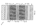
- FIG. 2 is a cross-sectional view of another embodiment of a graphite fiber heat dissipative structure
- FIG. 3 is a cross-sectional view of yet another embodiment of a graphite fiber heat dissipative structure.
- FIG. 1 Shown in FIG. 1 is a cross-sectional view of an embodiment of a multi-layer fibercore graphite structure 10.
- the embodiment of FIG. 1 includes two fibercore graphite layers 12, but it is to be appreciated that other quantities of fibercore graphite layers 12, for example, one, three, five or more fibercore graphite layers 12 may be utilized in the structure 10.
- Each fibercore graphite layer 12 includes a plurality of graphite fibers 14, with the volume between the graphite fibers 14 occupied by a volume of wax 16.
- the graphite fibers 14 are approximately 1.0 cm [0.40 inches] long, which results in a fibercore graphite layer 12 thickness of 1.0 cm [0.40 inches].
- a length of the graphic fibers 14 of the fibercore graphite layer 12 extends substantially from one layer of filler 18 to another layer of filler 18.
- a metallic sheet 22 which may be a nickel or other suitable material, is brazed to the filler 22.
- a metallic sheet 22 may be disposed between graphite layers 12 in the assembly.
- brazing of all layers 12 together may be accomplished in a single step. While the embodiments illustrated utilize a nickel metallic sheet 22 and a BNi-2 filler 18, in some embodiments, the metallic sheet 22 may be other nickel-based brazing alloys or of an alloy of titanium and titanium-containing fillers 18 may be utilized therewith.
- the sandwich structure is brazed to a substrate 24 formed from, for example, an aluminum material.
- the substrate 24 may be formed from other materials, such as stainless steel or nickel alloy where increased fluid combatibility is required, for example in a corrosive fluids environment.
- Brazing of the metallic sheet 22 to the substrate 24 is accomplished via an aluminum braze alloy 26 disposed between the metallic sheet 22 and the substrate 24.
- an endsheet 28 is located between the metallic sheet 22 and the substrate 24.
- the endsheet 28 is formed of, for example, aluminum multiclad, and is brazed to the metallic sheet 22 and the substrate 24 using aluminum braze alloy 26.
- two or more fibercore graphite layers 12 may be arranged side-to-side and joined via brazing.
- the metallic sheet 22 is omitted and only filler 18 is located between sides 30 of adjacent fibercore graphite layers 12.
- the filler 18 is located between the metallic sheet 22 and each fibercore graphite layer 12, wetting the graphite fibers 14.
- the filler 18 extends only partially along the length of the graphite fibers 14. Leaving a portion of the joint uncovered by filler 18 allows for more efficient filling of the gaps between graphite fibers 14 with wax 16 in later processing after the fibercore graphite layers 12 are joined.
- Location of filler 18 may be alternated throughout an assembly to promote flow of the wax 16 through the fibercore graphite layer 12 when filled. As shown in FIG. 3 , multiple layers may be constructed once the graphite layers 12 are joined side-to-side.
- the stack may include a metallic sheet 22 at the top and/or bottom of the assembly, and optionally a metallic sheet 22 may be disposed between fibercore graphite layers 12. In effect, a large brazed assembly of fibercore graphite layers 12, extending both in thickness and in length/width may be constructed.
- the joining of ends of graphite fibers 14 to a metallic sheet 22 into the sandwich structure results in an effectively longer graphite fiber 14 length.
- the taller fibercore height may be packaged into a more cubic structure (vs. a flat plate) which requires less external support during vibrational loading.
- the metallic sheet 22 / fibercore graphite layer 12 structure is less susceptible to handling damage and can be shaped by a variety of processes, for example, electrical discharge machining (EDM), to produce desired shapes to close tolerances.
- EDM electrical discharge machining
Landscapes
- Engineering & Computer Science (AREA)
- Mechanical Engineering (AREA)
- Chemical & Material Sciences (AREA)
- Materials Engineering (AREA)
- Laminated Bodies (AREA)
Description
- The subject matter disclosed herein generally relates to graphite fibers joined to a substrate material. More particularly, the subject matter disclosed herein relates to graphite fiber and substrate structures for heat exchanger systems.
-
US2004/222090 A1 , representing the most relevant state of the art, describes a method of assembling a metallic-graphite structure comprising the steps of arranging one or more layers of graphite fiber material, locating at least one metallic sheet adjacent to the one or more layers of graphite fiber material, and securing the at least one metallic sheet to the one or more layers of graphite fiber material via brazing. -
US 6047876 discloses a process for use in the construction or repair of heat exchangers comprising soldering a copper sheet onto a support made of carbon fiber-reinforced graphite. - Fibercore graphite is another material utilized, for example, in heat exchange applications. The material comprises an array of graphite fibers with a filler of a wax material therebetween. Large pieces of the fibercore are typically bonded to a desired surface, for example, an aluminum component, via an adhesive. Thermal mismatch issues are common between bulk graphite and graphite foam when joined to a metallic substrate. Fibercore graphite is not a monolithic structure and as such accommodates the thermal mismatch by translating with the substrate during thermal processing. Further, the thickness of the fibercore, which is relative to a length of the graphite fibers in the fibercore, is limited due to capability of graphite fiber production. The relatively thin fibercore material is fragile and is subject to breakage and damage when handling and/or shaping by machining or the like into desired shapes. The art would well receive a more robust structure of fibercore, which is not as sensitive to handling and/or other processing and which improves the thermal mismatch issues that exist in current structures.
- Viewed from a first aspect, the present invention provides a method of assembling a metallic-graphite structure as defined in claim 1.
- Viewed from a second aspect, the present invention provides a metallic-graphite structure as defined in claim 9.
- These and other advantages and features will become more apparent from the following description taken in conjunction with the drawings.
- The subject matter, which is regarded as the invention, is particularly pointed out and distinctly claimed in the claims at the conclusion of the specification. The foregoing and other features, and advantages of the invention are apparent from the following detailed description taken in conjunction with the accompanying drawings in which:
-
FIG. 1 is a cross-sectional view of an embodiment of a graphite fiber heat dissipative structure; -
FIG. 2 is a cross-sectional view of another embodiment of a graphite fiber heat dissipative structure; and -
FIG. 3 is a cross-sectional view of yet another embodiment of a graphite fiber heat dissipative structure. - The detailed description explains embodiments of the invention, together with advantages and features, by way of example with reference to the drawings.
- Shown in
FIG. 1 is a cross-sectional view of an embodiment of a multi-layerfibercore graphite structure 10. The embodiment ofFIG. 1 includes twofibercore graphite layers 12, but it is to be appreciated that other quantities offibercore graphite layers 12, for example, one, three, five or morefibercore graphite layers 12 may be utilized in thestructure 10. Eachfibercore graphite layer 12 includes a plurality ofgraphite fibers 14, with the volume between thegraphite fibers 14 occupied by a volume ofwax 16. In one embodiment, thegraphite fibers 14 are approximately 1.0 cm [0.40 inches] long, which results in afibercore graphite layer 12 thickness of 1.0 cm [0.40 inches]. It is to be appreciated, though, that other lengths ofgraphite fibers 14, resulting in other thicknesses offibercore graphite layers 12, may be utilized. In embodiments wherelonger graphite fibers 14 are utilized, the fibers may be arranged with a greater density to resist buckling of thegraphite fibers 14. - A layer of
braze filler 18, for example a BNi-2 filler, is utilized between thefibercore graphite layers 12 to join the layers offibercore graphite 12. In this embodiment, a length of thegraphic fibers 14 of thefibercore graphite layer 12 extends substantially from one layer offiller 18 to another layer offiller 18. In some embodiments, at each upper andlower end 20 of the assembly, ametallic sheet 22, which may be a nickel or other suitable material, is brazed to thefiller 22. Additionally, in some embodiments, ametallic sheet 22 may be disposed betweengraphite layers 12 in the assembly. In embodiments where more than onefibercore graphite layer 12 is utilized, brazing of alllayers 12 together may be accomplished in a single step. While the embodiments illustrated utilize a nickelmetallic sheet 22 and a BNi-2filler 18, in some embodiments, themetallic sheet 22 may be other nickel-based brazing alloys or of an alloy of titanium and titanium-containingfillers 18 may be utilized therewith. - The sandwich structure is brazed to a
substrate 24 formed from, for example, an aluminum material. Alternatively, thesubstrate 24 may be formed from other materials, such as stainless steel or nickel alloy where increased fluid combatibility is required, for example in a corrosive fluids environment. Brazing of themetallic sheet 22 to thesubstrate 24 is accomplished via analuminum braze alloy 26 disposed between themetallic sheet 22 and thesubstrate 24. In some embodiments, as shown inFIG. 2 , anendsheet 28 is located between themetallic sheet 22 and thesubstrate 24. Theendsheet 28 is formed of, for example, aluminum multiclad, and is brazed to themetallic sheet 22 and thesubstrate 24 usingaluminum braze alloy 26. - In some embodiments, as shown in
FIG. 3 , two or morefibercore graphite layers 12 may be arranged side-to-side and joined via brazing. In these embodiments, themetallic sheet 22 is omitted and onlyfiller 18 is located between sides 30 of adjacentfibercore graphite layers 12. To accomplish the brazing operation, thefiller 18 is located between themetallic sheet 22 and eachfibercore graphite layer 12, wetting thegraphite fibers 14. When joiningfibercore graphite layers 12 side-to-side, thefiller 18 extends only partially along the length of thegraphite fibers 14. Leaving a portion of the joint uncovered byfiller 18 allows for more efficient filling of the gaps betweengraphite fibers 14 withwax 16 in later processing after thefibercore graphite layers 12 are joined. Location offiller 18 may be alternated throughout an assembly to promote flow of thewax 16 through thefibercore graphite layer 12 when filled. As shown inFIG. 3 , multiple layers may be constructed once thegraphite layers 12 are joined side-to-side. The stack may include ametallic sheet 22 at the top and/or bottom of the assembly, and optionally ametallic sheet 22 may be disposed betweenfibercore graphite layers 12. In effect, a large brazed assembly offibercore graphite layers 12, extending both in thickness and in length/width may be constructed. - The joining of ends of
graphite fibers 14 to ametallic sheet 22 into the sandwich structure results in an effectivelylonger graphite fiber 14 length. The taller fibercore height may be packaged into a more cubic structure (vs. a flat plate) which requires less external support during vibrational loading. Further, themetallic sheet 22 /fibercore graphite layer 12 structure is less susceptible to handling damage and can be shaped by a variety of processes, for example, electrical discharge machining (EDM), to produce desired shapes to close tolerances. - While the invention has been described in detail in connection with only a limited number of embodiments, it should be readily understood that the invention is not limited to such disclosed embodiments. Rather, the invention can be modified to incorporate any number of variations, alterations, substitutions or equivalent arrangements not heretofore described, but which are commensurate with the scope of the invention as defined by the claims. Additionally, while various embodiments of the invention have been described, it is to be understood that aspects of the invention may include only some of the described embodiments. Accordingly, the invention is not to be seen as limited by the foregoing description, but is only limited by the scope of the appended claims.
Claims (15)
- A method of assembling a metallic-graphite structure (10) characterised by:arranging one or more layers of graphite fiber material (12), wherein each of the one or more layers of graphite material (12) comprises a plurality of graphite fibers (14) interposed with a volume of wax material (16);locating at least one metallic sheet (18) adjacent to the one or more layers of graphite fiber material (12); andsecuring the at least one metallic sheet (18) to the one or more layers of graphite fiber material (12) via brazing.
- The method of Claim 1 comprising securing the at least one metallic sheet (18) to a heat exchanger (24) via brazing.
- The method of Claim 2 wherein the heat exchanger (24) is formed from aluminum or an aluminum-containing alloy.
- The method of Claim 1, 2 or 3 wherein a length of the plurality of graphite fibers (14) in the graphite fiber material (12) extends from a first metallic sheet (18) of the at least one metallic sheet (18) to a second metallic sheet (18) of the at least one metallic sheet (18).
- The method of Claim 4 comprising stacking two or more layers of graphite fiber material (12) to increase an effective length of the plurality of graphite fibers (14).
- The method of Claim 5, wherein at least one metallic sheet (18) is disposed between adjacent layers of the two or more layers of graphite fiber material (12).
- The method of any preceding Claim wherein the at least one metallic sheet (18) is formed from a nickel material.
- The method of any of Claims 1 to 6 wherein the at least one metallic sheet (18) is formed from a material containing titanium.
- A metallic-graphite structure (10) characterised by:one or more layers of graphite fiber material (12), wherein each of the one or more layers of graphite fiber material (12) comprises a plurality of graphite fibers (14) interposed with a volume of wax material (16); andat least one metallic sheet (18) adjacent to the one or more layers of graphite fiber material (12) and secured thereto by brazing.
- The metallic-graphite structure (10) of Claim 9 comprising a heat exchanger (24) secured to the at least one metallic sheet (18) via brazing; preferably wherein the heat exchanger (24) is formed from aluminum or an aluminum-containing alloy.
- The metallic-graphite structure (10) of Claim 9 or 10 wherein a length of the plurality of graphite fibers (14) extends from a first metallic sheet (18) of the at least one metallic sheet (18) to a second metallic sheet (18) of the at least one metallic sheet (18).
- The metallic-graphite structure (10) of Claim 11 comprising two or more layers of graphite fiber material (12) stacked to increase an effective length of the plurality of graphite fibers (14).
- The metallic-graphite structure (10) of Claim 12, wherein at least one metallic sheet (18) is disposed between adjacent layers of the two or more layers of graphite fiber material (12).
- The metallic-graphite structure (10) of any of Claims 9 to 13 wherein the at least one metallic sheet (18) is formed from a nickel material.
- The metallic-graphite structure (10) of any of Claims 9 to 13 wherein the at least one metallic sheet (18) is formed from a material containing titanium.
Applications Claiming Priority (1)
| Application Number | Priority Date | Filing Date | Title |
|---|---|---|---|
| US12/623,705 US20110123823A1 (en) | 2009-11-23 | 2009-11-23 | Method of joining graphite fibers to a substrate |
Publications (2)
| Publication Number | Publication Date |
|---|---|
| EP2324946A1 EP2324946A1 (en) | 2011-05-25 |
| EP2324946B1 true EP2324946B1 (en) | 2014-01-15 |
Family
ID=43598320
Family Applications (1)
| Application Number | Title | Priority Date | Filing Date |
|---|---|---|---|
| EP10251978.2A Active EP2324946B1 (en) | 2009-11-23 | 2010-11-22 | Method of joining graphite fibers to a substrate via brazing ; corresponding metallic-graphite structure |
Country Status (2)
| Country | Link |
|---|---|
| US (1) | US20110123823A1 (en) |
| EP (1) | EP2324946B1 (en) |
Families Citing this family (3)
| Publication number | Priority date | Publication date | Assignee | Title |
|---|---|---|---|---|
| EP2679327A3 (en) * | 2012-06-27 | 2016-12-07 | Hamilton Sundstrand Space Systems International, Inc. | Method of brazing graphite fibers to a substrate |
| US20160209128A1 (en) * | 2015-01-15 | 2016-07-21 | Hamilton Sundstrand Space Systems International, Inc. | Composite passive heat sink system and method |
| CN116026021A (en) * | 2022-10-31 | 2023-04-28 | 广东美的暖通设备有限公司 | Pipeline integrated module, air conditioner outdoor unit and preparation method of pipeline integrated module |
Family Cites Families (16)
| Publication number | Priority date | Publication date | Assignee | Title |
|---|---|---|---|---|
| JPH0651871B2 (en) * | 1986-06-16 | 1994-07-06 | ル・カルボンヌ・ロレーヌ | Thermal contact with high transfer coefficient, and method and apparatus for cooling structures subject to high heat flux |
| AT389832B (en) * | 1988-08-01 | 1990-02-12 | Plansee Metallwerk | SOLDER CONNECTION |
| US5058537A (en) * | 1989-04-21 | 1991-10-22 | Paul Marius A | Optimized high pressure internal combustion engines |
| US6047876A (en) * | 1997-09-12 | 2000-04-11 | Materials Resources International | Process of using an active solder alloy |
| FR2787737B1 (en) * | 1998-12-23 | 2001-01-19 | Commissariat Energie Atomique | SOLDERING COMPOSITION, METHOD FOR ASSEMBLING PARTS OF ALUMINA-BASED MATERIALS BY REFRACTORY BRAZING WITH SAID SOLDERING COMPOSITION, ASSEMBLY AND REFRACTORY JOINT THUS OBTAINED |
| US20040009353A1 (en) * | 1999-06-14 | 2004-01-15 | Knowles Timothy R. | PCM/aligned fiber composite thermal interface |
| US6596139B2 (en) * | 2000-05-31 | 2003-07-22 | Honeywell International Inc. | Discontinuous high-modulus fiber metal matrix composite for physical vapor deposition target backing plates and other thermal management applications |
| DE10146368A1 (en) * | 2000-09-22 | 2002-06-06 | Denso Corp | Heat exchanger |
| DE10251658B4 (en) * | 2002-11-01 | 2005-08-25 | Atotech Deutschland Gmbh | Method for connecting microstructured component layers suitable for the production of microstructure components and microstructured component |
| US6877651B2 (en) * | 2002-12-02 | 2005-04-12 | Thomas A. Sandin | Method of joining ceramic or graphite to metal with an alloy having high nickel or cobalt content, alloys for joining the same, and products formed therewith |
| US20040222090A1 (en) * | 2003-05-07 | 2004-11-11 | Tim Scott | Carbon fiber and copper support for physical vapor deposition target assemblies |
| US7537151B2 (en) * | 2004-01-21 | 2009-05-26 | Delphi Technologies, Inc. | Method of making high performance heat sinks |
| US7726385B2 (en) * | 2004-02-23 | 2010-06-01 | International Business Machines Corporation | Heat dissipation interface for semiconductor chip structures |
| US7179558B2 (en) * | 2004-07-15 | 2007-02-20 | Delphi Technologies, Inc. | Braze alloy containing particulate material |
| US7331381B2 (en) * | 2006-02-16 | 2008-02-19 | Allcomp, Inc. | Hybrid heat exchangers |
| JP2009004666A (en) * | 2007-06-25 | 2009-01-08 | Hitachi Ltd | Power semiconductor module and manufacturing method thereof |
-
2009
- 2009-11-23 US US12/623,705 patent/US20110123823A1/en not_active Abandoned
-
2010
- 2010-11-22 EP EP10251978.2A patent/EP2324946B1/en active Active
Also Published As
| Publication number | Publication date |
|---|---|
| EP2324946A1 (en) | 2011-05-25 |
| US20110123823A1 (en) | 2011-05-26 |
Similar Documents
| Publication | Publication Date | Title |
|---|---|---|
| JP5282112B2 (en) | Cold plate assembly and method of manufacturing cold plate assembly | |
| US8177932B2 (en) | Method for manufacturing a micro tube heat exchanger | |
| US8646677B2 (en) | Method of joining graphite fibers to a substrate | |
| JP7110390B2 (en) | Diffusion bonded heat exchanger | |
| EP2131640A1 (en) | Thermal management device and method for making the same | |
| JP2010151352A (en) | Method of manufacturing heat transport device, and heat transport device | |
| US20190285363A1 (en) | Integral heat exchanger core reinforcement | |
| CN107167000A (en) | The method of heat-exchangers of the plate type and manufacture heat-exchangers of the plate type | |
| EP2324946A1 (en) | Method of joining graphite fibers to a substrate via brazing | |
| CN105324626B (en) | Heat exchanger with dual function dispensing head connection assembly | |
| EP2550676B1 (en) | Ic package stiffener with beam | |
| KR100992961B1 (en) | Heat exchanger in plate type | |
| US8347503B2 (en) | Methods of manufacturing brazed aluminum heat exchangers | |
| WO2015150321A2 (en) | Heat exchanger and method of making a heat exchanger | |
| EP2679327A2 (en) | Method of brazing graphite fibers to a substrate | |
| JP2014202390A (en) | Heat exchanger manufacturing method and heat exchanger | |
| JP2001241870A (en) | Small-diameter tunnel plate heat pipe | |
| EP3540355B1 (en) | Integral heat exchanger mounts | |
| EP3598054B1 (en) | Fin-plate heat exchanger | |
| JP5764116B2 (en) | Heat exchanger | |
| WO2024112413A1 (en) | Furnace braze cycle enhancement | |
| Beringer et al. | Method of Joining Graphite Fibers to a Substrate | |
| JP7591894B2 (en) | Stacked Heat Exchanger | |
| WO2015081274A1 (en) | Flattened envelope heat exchanger | |
| JP2009287918A (en) | Laminated structure reinforcing method by two-layer brazing |
Legal Events
| Date | Code | Title | Description |
|---|---|---|---|
| PUAI | Public reference made under article 153(3) epc to a published international application that has entered the european phase |
Free format text: ORIGINAL CODE: 0009012 |
|
| AK | Designated contracting states |
Kind code of ref document: A1 Designated state(s): AL AT BE BG CH CY CZ DE DK EE ES FI FR GB GR HR HU IE IS IT LI LT LU LV MC MK MT NL NO PL PT RO RS SE SI SK SM TR |
|
| AX | Request for extension of the european patent |
Extension state: BA ME |
|
| RAP1 | Party data changed (applicant data changed or rights of an application transferred) |
Owner name: HAMILTON SUNDSTRAND SPACE SYSTEMS INTERNATIONAL, I |
|
| 17P | Request for examination filed |
Effective date: 20111110 |
|
| GRAP | Despatch of communication of intention to grant a patent |
Free format text: ORIGINAL CODE: EPIDOSNIGR1 |
|
| RIC1 | Information provided on ipc code assigned before grant |
Ipc: B23K 1/19 20060101ALI20130715BHEP Ipc: B23K 1/00 20060101AFI20130715BHEP |
|
| INTG | Intention to grant announced |
Effective date: 20130802 |
|
| GRAS | Grant fee paid |
Free format text: ORIGINAL CODE: EPIDOSNIGR3 |
|
| GRAA | (expected) grant |
Free format text: ORIGINAL CODE: 0009210 |
|
| AK | Designated contracting states |
Kind code of ref document: B1 Designated state(s): AL AT BE BG CH CY CZ DE DK EE ES FI FR GB GR HR HU IE IS IT LI LT LU LV MC MK MT NL NO PL PT RO RS SE SI SK SM TR |
|
| REG | Reference to a national code |
Ref country code: GB Ref legal event code: FG4D Ref country code: CH Ref legal event code: EP |
|
| REG | Reference to a national code |
Ref country code: NL Ref legal event code: T3 |
|
| REG | Reference to a national code |
Ref country code: AT Ref legal event code: REF Ref document number: 649567 Country of ref document: AT Kind code of ref document: T Effective date: 20140215 |
|
| REG | Reference to a national code |
Ref country code: IE Ref legal event code: FG4D |
|
| REG | Reference to a national code |
Ref country code: DE Ref legal event code: R096 Ref document number: 602010013116 Country of ref document: DE Effective date: 20140227 |
|
| REG | Reference to a national code |
Ref country code: AT Ref legal event code: MK05 Ref document number: 649567 Country of ref document: AT Kind code of ref document: T Effective date: 20140115 |
|
| REG | Reference to a national code |
Ref country code: LT Ref legal event code: MG4D |
|
| PG25 | Lapsed in a contracting state [announced via postgrant information from national office to epo] |
Ref country code: LT Free format text: LAPSE BECAUSE OF FAILURE TO SUBMIT A TRANSLATION OF THE DESCRIPTION OR TO PAY THE FEE WITHIN THE PRESCRIBED TIME-LIMIT Effective date: 20140115 Ref country code: IS Free format text: LAPSE BECAUSE OF FAILURE TO SUBMIT A TRANSLATION OF THE DESCRIPTION OR TO PAY THE FEE WITHIN THE PRESCRIBED TIME-LIMIT Effective date: 20140515 Ref country code: NO Free format text: LAPSE BECAUSE OF FAILURE TO SUBMIT A TRANSLATION OF THE DESCRIPTION OR TO PAY THE FEE WITHIN THE PRESCRIBED TIME-LIMIT Effective date: 20140415 |
|
| PG25 | Lapsed in a contracting state [announced via postgrant information from national office to epo] |
Ref country code: AT Free format text: LAPSE BECAUSE OF FAILURE TO SUBMIT A TRANSLATION OF THE DESCRIPTION OR TO PAY THE FEE WITHIN THE PRESCRIBED TIME-LIMIT Effective date: 20140115 Ref country code: CY Free format text: LAPSE BECAUSE OF FAILURE TO SUBMIT A TRANSLATION OF THE DESCRIPTION OR TO PAY THE FEE WITHIN THE PRESCRIBED TIME-LIMIT Effective date: 20140115 Ref country code: PT Free format text: LAPSE BECAUSE OF FAILURE TO SUBMIT A TRANSLATION OF THE DESCRIPTION OR TO PAY THE FEE WITHIN THE PRESCRIBED TIME-LIMIT Effective date: 20140515 Ref country code: SE Free format text: LAPSE BECAUSE OF FAILURE TO SUBMIT A TRANSLATION OF THE DESCRIPTION OR TO PAY THE FEE WITHIN THE PRESCRIBED TIME-LIMIT Effective date: 20140115 Ref country code: ES Free format text: LAPSE BECAUSE OF FAILURE TO SUBMIT A TRANSLATION OF THE DESCRIPTION OR TO PAY THE FEE WITHIN THE PRESCRIBED TIME-LIMIT Effective date: 20140115 Ref country code: FI Free format text: LAPSE BECAUSE OF FAILURE TO SUBMIT A TRANSLATION OF THE DESCRIPTION OR TO PAY THE FEE WITHIN THE PRESCRIBED TIME-LIMIT Effective date: 20140115 |
|
| PG25 | Lapsed in a contracting state [announced via postgrant information from national office to epo] |
Ref country code: HR Free format text: LAPSE BECAUSE OF FAILURE TO SUBMIT A TRANSLATION OF THE DESCRIPTION OR TO PAY THE FEE WITHIN THE PRESCRIBED TIME-LIMIT Effective date: 20140115 Ref country code: RS Free format text: LAPSE BECAUSE OF FAILURE TO SUBMIT A TRANSLATION OF THE DESCRIPTION OR TO PAY THE FEE WITHIN THE PRESCRIBED TIME-LIMIT Effective date: 20140115 Ref country code: LV Free format text: LAPSE BECAUSE OF FAILURE TO SUBMIT A TRANSLATION OF THE DESCRIPTION OR TO PAY THE FEE WITHIN THE PRESCRIBED TIME-LIMIT Effective date: 20140115 Ref country code: BE Free format text: LAPSE BECAUSE OF FAILURE TO SUBMIT A TRANSLATION OF THE DESCRIPTION OR TO PAY THE FEE WITHIN THE PRESCRIBED TIME-LIMIT Effective date: 20140115 |
|
| REG | Reference to a national code |
Ref country code: DE Ref legal event code: R097 Ref document number: 602010013116 Country of ref document: DE |
|
| PG25 | Lapsed in a contracting state [announced via postgrant information from national office to epo] |
Ref country code: EE Free format text: LAPSE BECAUSE OF FAILURE TO SUBMIT A TRANSLATION OF THE DESCRIPTION OR TO PAY THE FEE WITHIN THE PRESCRIBED TIME-LIMIT Effective date: 20140115 Ref country code: CZ Free format text: LAPSE BECAUSE OF FAILURE TO SUBMIT A TRANSLATION OF THE DESCRIPTION OR TO PAY THE FEE WITHIN THE PRESCRIBED TIME-LIMIT Effective date: 20140115 Ref country code: DK Free format text: LAPSE BECAUSE OF FAILURE TO SUBMIT A TRANSLATION OF THE DESCRIPTION OR TO PAY THE FEE WITHIN THE PRESCRIBED TIME-LIMIT Effective date: 20140115 Ref country code: RO Free format text: LAPSE BECAUSE OF FAILURE TO SUBMIT A TRANSLATION OF THE DESCRIPTION OR TO PAY THE FEE WITHIN THE PRESCRIBED TIME-LIMIT Effective date: 20140115 |
|
| PLBE | No opposition filed within time limit |
Free format text: ORIGINAL CODE: 0009261 |
|
| STAA | Information on the status of an ep patent application or granted ep patent |
Free format text: STATUS: NO OPPOSITION FILED WITHIN TIME LIMIT |
|
| PG25 | Lapsed in a contracting state [announced via postgrant information from national office to epo] |
Ref country code: PL Free format text: LAPSE BECAUSE OF FAILURE TO SUBMIT A TRANSLATION OF THE DESCRIPTION OR TO PAY THE FEE WITHIN THE PRESCRIBED TIME-LIMIT Effective date: 20140115 Ref country code: SK Free format text: LAPSE BECAUSE OF FAILURE TO SUBMIT A TRANSLATION OF THE DESCRIPTION OR TO PAY THE FEE WITHIN THE PRESCRIBED TIME-LIMIT Effective date: 20140115 |
|
| 26N | No opposition filed |
Effective date: 20141016 |
|
| REG | Reference to a national code |
Ref country code: DE Ref legal event code: R097 Ref document number: 602010013116 Country of ref document: DE Effective date: 20141016 |
|
| PG25 | Lapsed in a contracting state [announced via postgrant information from national office to epo] |
Ref country code: SI Free format text: LAPSE BECAUSE OF FAILURE TO SUBMIT A TRANSLATION OF THE DESCRIPTION OR TO PAY THE FEE WITHIN THE PRESCRIBED TIME-LIMIT Effective date: 20140115 |
|
| REG | Reference to a national code |
Ref country code: DE Ref legal event code: R119 Ref document number: 602010013116 Country of ref document: DE |
|
| PG25 | Lapsed in a contracting state [announced via postgrant information from national office to epo] |
Ref country code: MC Free format text: LAPSE BECAUSE OF FAILURE TO SUBMIT A TRANSLATION OF THE DESCRIPTION OR TO PAY THE FEE WITHIN THE PRESCRIBED TIME-LIMIT Effective date: 20140115 Ref country code: LU Free format text: LAPSE BECAUSE OF FAILURE TO SUBMIT A TRANSLATION OF THE DESCRIPTION OR TO PAY THE FEE WITHIN THE PRESCRIBED TIME-LIMIT Effective date: 20141122 |
|
| REG | Reference to a national code |
Ref country code: CH Ref legal event code: PL |
|
| GBPC | Gb: european patent ceased through non-payment of renewal fee |
Effective date: 20141122 |
|
| PG25 | Lapsed in a contracting state [announced via postgrant information from national office to epo] |
Ref country code: CH Free format text: LAPSE BECAUSE OF NON-PAYMENT OF DUE FEES Effective date: 20141130 Ref country code: LI Free format text: LAPSE BECAUSE OF NON-PAYMENT OF DUE FEES Effective date: 20141130 |
|
| REG | Reference to a national code |
Ref country code: IE Ref legal event code: MM4A |
|
| REG | Reference to a national code |
Ref country code: FR Ref legal event code: ST Effective date: 20150731 |
|
| PG25 | Lapsed in a contracting state [announced via postgrant information from national office to epo] |
Ref country code: GB Free format text: LAPSE BECAUSE OF NON-PAYMENT OF DUE FEES Effective date: 20141122 Ref country code: DE Free format text: LAPSE BECAUSE OF NON-PAYMENT OF DUE FEES Effective date: 20150602 Ref country code: IE Free format text: LAPSE BECAUSE OF NON-PAYMENT OF DUE FEES Effective date: 20141122 |
|
| PG25 | Lapsed in a contracting state [announced via postgrant information from national office to epo] |
Ref country code: FR Free format text: LAPSE BECAUSE OF NON-PAYMENT OF DUE FEES Effective date: 20141201 |
|
| PG25 | Lapsed in a contracting state [announced via postgrant information from national office to epo] |
Ref country code: SM Free format text: LAPSE BECAUSE OF FAILURE TO SUBMIT A TRANSLATION OF THE DESCRIPTION OR TO PAY THE FEE WITHIN THE PRESCRIBED TIME-LIMIT Effective date: 20140115 |
|
| PG25 | Lapsed in a contracting state [announced via postgrant information from national office to epo] |
Ref country code: BG Free format text: LAPSE BECAUSE OF FAILURE TO SUBMIT A TRANSLATION OF THE DESCRIPTION OR TO PAY THE FEE WITHIN THE PRESCRIBED TIME-LIMIT Effective date: 20140115 Ref country code: GR Free format text: LAPSE BECAUSE OF FAILURE TO SUBMIT A TRANSLATION OF THE DESCRIPTION OR TO PAY THE FEE WITHIN THE PRESCRIBED TIME-LIMIT Effective date: 20140416 Ref country code: IT Free format text: LAPSE BECAUSE OF FAILURE TO SUBMIT A TRANSLATION OF THE DESCRIPTION OR TO PAY THE FEE WITHIN THE PRESCRIBED TIME-LIMIT Effective date: 20140115 |
|
| PG25 | Lapsed in a contracting state [announced via postgrant information from national office to epo] |
Ref country code: HU Free format text: LAPSE BECAUSE OF FAILURE TO SUBMIT A TRANSLATION OF THE DESCRIPTION OR TO PAY THE FEE WITHIN THE PRESCRIBED TIME-LIMIT; INVALID AB INITIO Effective date: 20101122 Ref country code: TR Free format text: LAPSE BECAUSE OF FAILURE TO SUBMIT A TRANSLATION OF THE DESCRIPTION OR TO PAY THE FEE WITHIN THE PRESCRIBED TIME-LIMIT Effective date: 20140115 Ref country code: MT Free format text: LAPSE BECAUSE OF FAILURE TO SUBMIT A TRANSLATION OF THE DESCRIPTION OR TO PAY THE FEE WITHIN THE PRESCRIBED TIME-LIMIT Effective date: 20140115 |
|
| PG25 | Lapsed in a contracting state [announced via postgrant information from national office to epo] |
Ref country code: MK Free format text: LAPSE BECAUSE OF FAILURE TO SUBMIT A TRANSLATION OF THE DESCRIPTION OR TO PAY THE FEE WITHIN THE PRESCRIBED TIME-LIMIT Effective date: 20140115 |
|
| PG25 | Lapsed in a contracting state [announced via postgrant information from national office to epo] |
Ref country code: AL Free format text: LAPSE BECAUSE OF FAILURE TO SUBMIT A TRANSLATION OF THE DESCRIPTION OR TO PAY THE FEE WITHIN THE PRESCRIBED TIME-LIMIT Effective date: 20140115 |
|
| PGFP | Annual fee paid to national office [announced via postgrant information from national office to epo] |
Ref country code: NL Payment date: 20251022 Year of fee payment: 16 |
|
| P01 | Opt-out of the competence of the unified patent court (upc) registered |
Free format text: CASE NUMBER: UPC_APP_0016470_2324946/2025 Effective date: 20251209 |