EP2324919A1 - Catalyst for exhaust gas purification - Google Patents
Catalyst for exhaust gas purification Download PDFInfo
- Publication number
- EP2324919A1 EP2324919A1 EP09813124A EP09813124A EP2324919A1 EP 2324919 A1 EP2324919 A1 EP 2324919A1 EP 09813124 A EP09813124 A EP 09813124A EP 09813124 A EP09813124 A EP 09813124A EP 2324919 A1 EP2324919 A1 EP 2324919A1
- Authority
- EP
- European Patent Office
- Prior art keywords
- catalyst
- mol
- exhaust gas
- slurry
- per unit
- Prior art date
- Legal status (The legal status is an assumption and is not a legal conclusion. Google has not performed a legal analysis and makes no representation as to the accuracy of the status listed.)
- Granted
Links
Images


Classifications
-
- F—MECHANICAL ENGINEERING; LIGHTING; HEATING; WEAPONS; BLASTING
- F01—MACHINES OR ENGINES IN GENERAL; ENGINE PLANTS IN GENERAL; STEAM ENGINES
- F01N—GAS-FLOW SILENCERS OR EXHAUST APPARATUS FOR MACHINES OR ENGINES IN GENERAL; GAS-FLOW SILENCERS OR EXHAUST APPARATUS FOR INTERNAL-COMBUSTION ENGINES
- F01N3/00—Exhaust or silencing apparatus having means for purifying, rendering innocuous, or otherwise treating exhaust
- F01N3/08—Exhaust or silencing apparatus having means for purifying, rendering innocuous, or otherwise treating exhaust for rendering innocuous
- F01N3/0807—Exhaust or silencing apparatus having means for purifying, rendering innocuous, or otherwise treating exhaust for rendering innocuous by using absorbents or adsorbents
-
- B—PERFORMING OPERATIONS; TRANSPORTING
- B01—PHYSICAL OR CHEMICAL PROCESSES OR APPARATUS IN GENERAL
- B01D—SEPARATION
- B01D53/00—Separation of gases or vapours; Recovering vapours of volatile solvents from gases; Chemical or biological purification of waste gases, e.g. engine exhaust gases, smoke, fumes, flue gases, aerosols
- B01D53/34—Chemical or biological purification of waste gases
- B01D53/92—Chemical or biological purification of waste gases of engine exhaust gases
- B01D53/94—Chemical or biological purification of waste gases of engine exhaust gases by catalytic processes
- B01D53/9404—Removing only nitrogen compounds
- B01D53/9409—Nitrogen oxides
- B01D53/9413—Processes characterised by a specific catalyst
-
- B—PERFORMING OPERATIONS; TRANSPORTING
- B01—PHYSICAL OR CHEMICAL PROCESSES OR APPARATUS IN GENERAL
- B01D—SEPARATION
- B01D53/00—Separation of gases or vapours; Recovering vapours of volatile solvents from gases; Chemical or biological purification of waste gases, e.g. engine exhaust gases, smoke, fumes, flue gases, aerosols
- B01D53/34—Chemical or biological purification of waste gases
- B01D53/92—Chemical or biological purification of waste gases of engine exhaust gases
- B01D53/94—Chemical or biological purification of waste gases of engine exhaust gases by catalytic processes
- B01D53/9459—Removing one or more of nitrogen oxides, carbon monoxide, or hydrocarbons by multiple successive catalytic functions; systems with more than one different function, e.g. zone coated catalysts
- B01D53/9463—Removing one or more of nitrogen oxides, carbon monoxide, or hydrocarbons by multiple successive catalytic functions; systems with more than one different function, e.g. zone coated catalysts with catalysts positioned on one brick
- B01D53/9472—Removing one or more of nitrogen oxides, carbon monoxide, or hydrocarbons by multiple successive catalytic functions; systems with more than one different function, e.g. zone coated catalysts with catalysts positioned on one brick in different zones
-
- B—PERFORMING OPERATIONS; TRANSPORTING
- B01—PHYSICAL OR CHEMICAL PROCESSES OR APPARATUS IN GENERAL
- B01J—CHEMICAL OR PHYSICAL PROCESSES, e.g. CATALYSIS OR COLLOID CHEMISTRY; THEIR RELEVANT APPARATUS
- B01J23/00—Catalysts comprising metals or metal oxides or hydroxides, not provided for in group B01J21/00
- B01J23/38—Catalysts comprising metals or metal oxides or hydroxides, not provided for in group B01J21/00 of noble metals
- B01J23/54—Catalysts comprising metals or metal oxides or hydroxides, not provided for in group B01J21/00 of noble metals combined with metals, oxides or hydroxides provided for in groups B01J23/02 - B01J23/36
- B01J23/56—Platinum group metals
- B01J23/63—Platinum group metals with rare earths or actinides
-
- B—PERFORMING OPERATIONS; TRANSPORTING
- B01—PHYSICAL OR CHEMICAL PROCESSES OR APPARATUS IN GENERAL
- B01J—CHEMICAL OR PHYSICAL PROCESSES, e.g. CATALYSIS OR COLLOID CHEMISTRY; THEIR RELEVANT APPARATUS
- B01J35/00—Catalysts, in general, characterised by their form or physical properties
- B01J35/19—Catalysts containing parts with different compositions
-
- B—PERFORMING OPERATIONS; TRANSPORTING
- B01—PHYSICAL OR CHEMICAL PROCESSES OR APPARATUS IN GENERAL
- B01J—CHEMICAL OR PHYSICAL PROCESSES, e.g. CATALYSIS OR COLLOID CHEMISTRY; THEIR RELEVANT APPARATUS
- B01J35/00—Catalysts, in general, characterised by their form or physical properties
- B01J35/50—Catalysts, in general, characterised by their form or physical properties characterised by their shape or configuration
- B01J35/56—Foraminous structures having flow-through passages or channels, e.g. grids or three-dimensional [3D] monoliths
-
- F—MECHANICAL ENGINEERING; LIGHTING; HEATING; WEAPONS; BLASTING
- F01—MACHINES OR ENGINES IN GENERAL; ENGINE PLANTS IN GENERAL; STEAM ENGINES
- F01N—GAS-FLOW SILENCERS OR EXHAUST APPARATUS FOR MACHINES OR ENGINES IN GENERAL; GAS-FLOW SILENCERS OR EXHAUST APPARATUS FOR INTERNAL-COMBUSTION ENGINES
- F01N13/00—Exhaust or silencing apparatus characterised by constructional features
- F01N13/009—Exhaust or silencing apparatus characterised by constructional features having two or more separate purifying devices arranged in series
- F01N13/0097—Exhaust or silencing apparatus characterised by constructional features having two or more separate purifying devices arranged in series the purifying devices are arranged in a single housing
-
- F—MECHANICAL ENGINEERING; LIGHTING; HEATING; WEAPONS; BLASTING
- F01—MACHINES OR ENGINES IN GENERAL; ENGINE PLANTS IN GENERAL; STEAM ENGINES
- F01N—GAS-FLOW SILENCERS OR EXHAUST APPARATUS FOR MACHINES OR ENGINES IN GENERAL; GAS-FLOW SILENCERS OR EXHAUST APPARATUS FOR INTERNAL-COMBUSTION ENGINES
- F01N3/00—Exhaust or silencing apparatus having means for purifying, rendering innocuous, or otherwise treating exhaust
- F01N3/08—Exhaust or silencing apparatus having means for purifying, rendering innocuous, or otherwise treating exhaust for rendering innocuous
- F01N3/0807—Exhaust or silencing apparatus having means for purifying, rendering innocuous, or otherwise treating exhaust for rendering innocuous by using absorbents or adsorbents
- F01N3/0828—Exhaust or silencing apparatus having means for purifying, rendering innocuous, or otherwise treating exhaust for rendering innocuous by using absorbents or adsorbents characterised by the absorbed or adsorbed substances
- F01N3/0864—Oxygen
-
- B—PERFORMING OPERATIONS; TRANSPORTING
- B01—PHYSICAL OR CHEMICAL PROCESSES OR APPARATUS IN GENERAL
- B01D—SEPARATION
- B01D2255/00—Catalysts
- B01D2255/10—Noble metals or compounds thereof
- B01D2255/102—Platinum group metals
- B01D2255/1021—Platinum
-
- B—PERFORMING OPERATIONS; TRANSPORTING
- B01—PHYSICAL OR CHEMICAL PROCESSES OR APPARATUS IN GENERAL
- B01D—SEPARATION
- B01D2255/00—Catalysts
- B01D2255/10—Noble metals or compounds thereof
- B01D2255/102—Platinum group metals
- B01D2255/1025—Rhodium
-
- B—PERFORMING OPERATIONS; TRANSPORTING
- B01—PHYSICAL OR CHEMICAL PROCESSES OR APPARATUS IN GENERAL
- B01D—SEPARATION
- B01D2255/00—Catalysts
- B01D2255/20—Metals or compounds thereof
- B01D2255/206—Rare earth metals
- B01D2255/2061—Yttrium
-
- B—PERFORMING OPERATIONS; TRANSPORTING
- B01—PHYSICAL OR CHEMICAL PROCESSES OR APPARATUS IN GENERAL
- B01D—SEPARATION
- B01D2255/00—Catalysts
- B01D2255/20—Metals or compounds thereof
- B01D2255/206—Rare earth metals
- B01D2255/2063—Lanthanum
-
- B—PERFORMING OPERATIONS; TRANSPORTING
- B01—PHYSICAL OR CHEMICAL PROCESSES OR APPARATUS IN GENERAL
- B01D—SEPARATION
- B01D2255/00—Catalysts
- B01D2255/20—Metals or compounds thereof
- B01D2255/206—Rare earth metals
- B01D2255/2065—Cerium
-
- B—PERFORMING OPERATIONS; TRANSPORTING
- B01—PHYSICAL OR CHEMICAL PROCESSES OR APPARATUS IN GENERAL
- B01D—SEPARATION
- B01D2255/00—Catalysts
- B01D2255/20—Metals or compounds thereof
- B01D2255/207—Transition metals
- B01D2255/20707—Titanium
-
- B—PERFORMING OPERATIONS; TRANSPORTING
- B01—PHYSICAL OR CHEMICAL PROCESSES OR APPARATUS IN GENERAL
- B01D—SEPARATION
- B01D2255/00—Catalysts
- B01D2255/20—Metals or compounds thereof
- B01D2255/207—Transition metals
- B01D2255/20715—Zirconium
-
- B—PERFORMING OPERATIONS; TRANSPORTING
- B01—PHYSICAL OR CHEMICAL PROCESSES OR APPARATUS IN GENERAL
- B01D—SEPARATION
- B01D2255/00—Catalysts
- B01D2255/20—Metals or compounds thereof
- B01D2255/207—Transition metals
- B01D2255/20769—Molybdenum
-
- B—PERFORMING OPERATIONS; TRANSPORTING
- B01—PHYSICAL OR CHEMICAL PROCESSES OR APPARATUS IN GENERAL
- B01D—SEPARATION
- B01D2255/00—Catalysts
- B01D2255/20—Metals or compounds thereof
- B01D2255/207—Transition metals
- B01D2255/20776—Tungsten
-
- B—PERFORMING OPERATIONS; TRANSPORTING
- B01—PHYSICAL OR CHEMICAL PROCESSES OR APPARATUS IN GENERAL
- B01D—SEPARATION
- B01D2255/00—Catalysts
- B01D2255/30—Silica
-
- B—PERFORMING OPERATIONS; TRANSPORTING
- B01—PHYSICAL OR CHEMICAL PROCESSES OR APPARATUS IN GENERAL
- B01D—SEPARATION
- B01D2255/00—Catalysts
- B01D2255/40—Mixed oxides
- B01D2255/407—Zr-Ce mixed oxides
-
- B—PERFORMING OPERATIONS; TRANSPORTING
- B01—PHYSICAL OR CHEMICAL PROCESSES OR APPARATUS IN GENERAL
- B01D—SEPARATION
- B01D2255/00—Catalysts
- B01D2255/90—Physical characteristics of catalysts
- B01D2255/908—O2-storage component incorporated in the catalyst
-
- B—PERFORMING OPERATIONS; TRANSPORTING
- B01—PHYSICAL OR CHEMICAL PROCESSES OR APPARATUS IN GENERAL
- B01D—SEPARATION
- B01D2255/00—Catalysts
- B01D2255/90—Physical characteristics of catalysts
- B01D2255/92—Dimensions
- B01D2255/9207—Specific surface
-
- B—PERFORMING OPERATIONS; TRANSPORTING
- B01—PHYSICAL OR CHEMICAL PROCESSES OR APPARATUS IN GENERAL
- B01D—SEPARATION
- B01D53/00—Separation of gases or vapours; Recovering vapours of volatile solvents from gases; Chemical or biological purification of waste gases, e.g. engine exhaust gases, smoke, fumes, flue gases, aerosols
- B01D53/34—Chemical or biological purification of waste gases
- B01D53/92—Chemical or biological purification of waste gases of engine exhaust gases
- B01D53/94—Chemical or biological purification of waste gases of engine exhaust gases by catalytic processes
- B01D53/9459—Removing one or more of nitrogen oxides, carbon monoxide, or hydrocarbons by multiple successive catalytic functions; systems with more than one different function, e.g. zone coated catalysts
- B01D53/9477—Removing one or more of nitrogen oxides, carbon monoxide, or hydrocarbons by multiple successive catalytic functions; systems with more than one different function, e.g. zone coated catalysts with catalysts positioned on separate bricks, e.g. exhaust systems
-
- B—PERFORMING OPERATIONS; TRANSPORTING
- B01—PHYSICAL OR CHEMICAL PROCESSES OR APPARATUS IN GENERAL
- B01J—CHEMICAL OR PHYSICAL PROCESSES, e.g. CATALYSIS OR COLLOID CHEMISTRY; THEIR RELEVANT APPARATUS
- B01J23/00—Catalysts comprising metals or metal oxides or hydroxides, not provided for in group B01J21/00
- B01J23/38—Catalysts comprising metals or metal oxides or hydroxides, not provided for in group B01J21/00 of noble metals
- B01J23/54—Catalysts comprising metals or metal oxides or hydroxides, not provided for in group B01J21/00 of noble metals combined with metals, oxides or hydroxides provided for in groups B01J23/02 - B01J23/36
- B01J23/56—Platinum group metals
- B01J23/64—Platinum group metals with arsenic, antimony, bismuth, vanadium, niobium, tantalum, polonium, chromium, molybdenum, tungsten, manganese, technetium or rhenium
- B01J23/648—Vanadium, niobium or tantalum or polonium
- B01J23/6484—Niobium
-
- B—PERFORMING OPERATIONS; TRANSPORTING
- B01—PHYSICAL OR CHEMICAL PROCESSES OR APPARATUS IN GENERAL
- B01J—CHEMICAL OR PHYSICAL PROCESSES, e.g. CATALYSIS OR COLLOID CHEMISTRY; THEIR RELEVANT APPARATUS
- B01J23/00—Catalysts comprising metals or metal oxides or hydroxides, not provided for in group B01J21/00
- B01J23/38—Catalysts comprising metals or metal oxides or hydroxides, not provided for in group B01J21/00 of noble metals
- B01J23/54—Catalysts comprising metals or metal oxides or hydroxides, not provided for in group B01J21/00 of noble metals combined with metals, oxides or hydroxides provided for in groups B01J23/02 - B01J23/36
- B01J23/56—Platinum group metals
- B01J23/64—Platinum group metals with arsenic, antimony, bismuth, vanadium, niobium, tantalum, polonium, chromium, molybdenum, tungsten, manganese, technetium or rhenium
- B01J23/652—Chromium, molybdenum or tungsten
- B01J23/6525—Molybdenum
-
- B—PERFORMING OPERATIONS; TRANSPORTING
- B01—PHYSICAL OR CHEMICAL PROCESSES OR APPARATUS IN GENERAL
- B01J—CHEMICAL OR PHYSICAL PROCESSES, e.g. CATALYSIS OR COLLOID CHEMISTRY; THEIR RELEVANT APPARATUS
- B01J23/00—Catalysts comprising metals or metal oxides or hydroxides, not provided for in group B01J21/00
- B01J23/38—Catalysts comprising metals or metal oxides or hydroxides, not provided for in group B01J21/00 of noble metals
- B01J23/54—Catalysts comprising metals or metal oxides or hydroxides, not provided for in group B01J21/00 of noble metals combined with metals, oxides or hydroxides provided for in groups B01J23/02 - B01J23/36
- B01J23/56—Platinum group metals
- B01J23/64—Platinum group metals with arsenic, antimony, bismuth, vanadium, niobium, tantalum, polonium, chromium, molybdenum, tungsten, manganese, technetium or rhenium
- B01J23/652—Chromium, molybdenum or tungsten
- B01J23/6527—Tungsten
-
- B—PERFORMING OPERATIONS; TRANSPORTING
- B01—PHYSICAL OR CHEMICAL PROCESSES OR APPARATUS IN GENERAL
- B01J—CHEMICAL OR PHYSICAL PROCESSES, e.g. CATALYSIS OR COLLOID CHEMISTRY; THEIR RELEVANT APPARATUS
- B01J27/00—Catalysts comprising the elements or compounds of halogens, sulfur, selenium, tellurium, phosphorus or nitrogen; Catalysts comprising carbon compounds
- B01J27/14—Phosphorus; Compounds thereof
-
- F—MECHANICAL ENGINEERING; LIGHTING; HEATING; WEAPONS; BLASTING
- F01—MACHINES OR ENGINES IN GENERAL; ENGINE PLANTS IN GENERAL; STEAM ENGINES
- F01N—GAS-FLOW SILENCERS OR EXHAUST APPARATUS FOR MACHINES OR ENGINES IN GENERAL; GAS-FLOW SILENCERS OR EXHAUST APPARATUS FOR INTERNAL-COMBUSTION ENGINES
- F01N2370/00—Selection of materials for exhaust purification
- F01N2370/02—Selection of materials for exhaust purification used in catalytic reactors
-
- F—MECHANICAL ENGINEERING; LIGHTING; HEATING; WEAPONS; BLASTING
- F01—MACHINES OR ENGINES IN GENERAL; ENGINE PLANTS IN GENERAL; STEAM ENGINES
- F01N—GAS-FLOW SILENCERS OR EXHAUST APPARATUS FOR MACHINES OR ENGINES IN GENERAL; GAS-FLOW SILENCERS OR EXHAUST APPARATUS FOR INTERNAL-COMBUSTION ENGINES
- F01N2510/00—Surface coverings
- F01N2510/06—Surface coverings for exhaust purification, e.g. catalytic reaction
- F01N2510/068—Surface coverings for exhaust purification, e.g. catalytic reaction characterised by the distribution of the catalytic coatings
- F01N2510/0682—Surface coverings for exhaust purification, e.g. catalytic reaction characterised by the distribution of the catalytic coatings having a discontinuous, uneven or partially overlapping coating of catalytic material, e.g. higher amount of material upstream than downstream or vice versa
-
- Y—GENERAL TAGGING OF NEW TECHNOLOGICAL DEVELOPMENTS; GENERAL TAGGING OF CROSS-SECTIONAL TECHNOLOGIES SPANNING OVER SEVERAL SECTIONS OF THE IPC; TECHNICAL SUBJECTS COVERED BY FORMER USPC CROSS-REFERENCE ART COLLECTIONS [XRACs] AND DIGESTS
- Y02—TECHNOLOGIES OR APPLICATIONS FOR MITIGATION OR ADAPTATION AGAINST CLIMATE CHANGE
- Y02T—CLIMATE CHANGE MITIGATION TECHNOLOGIES RELATED TO TRANSPORTATION
- Y02T10/00—Road transport of goods or passengers
- Y02T10/10—Internal combustion engine [ICE] based vehicles
- Y02T10/12—Improving ICE efficiencies
Definitions
- the present invention relates to an exhaust gas-purifying catalyst.
- Patent Document 1 discloses an exhaust gas-purifying catalyst containing a support containing cerium oxide, and a precious metal supported by this support.
- the cerium oxide has high oxygen storage capability and is known to be a component effective to improve the performance of an exhaust gas-purifying catalyst.
- Ni is specified as an environmental load substance in many countries and districts. Therefore, exhaust gas-purifying catalysts containing a relatively large amount of Ni have come to be unusable.
- an exhaust gas-purifying catalyst comprising: a substrate provided with one or more through-holes through which exhaust gas flows; and a catalyst layer supported by the substrate and containing precious metals and an oxygen storage material, the exhaust gas-purifying catalyst comprising a first part to which the exhaust gas is supplied, and a second part to which the exhaust gas having passed through the first part is supplied and is smaller in the content of the oxygen storage material per unit volume than the first part.
- the inventors of the present invention have found in the course of making studies concerning the cause of generation of H 2 S and, particularly, the cause of generation of H 2 S after a vehicle halts, that there is a difference in the cooling speeds of the catalyst depending on the positions therein.
- an exhaust gas-purifying catalyst comprising a catalyst layer uniformly containing a precious metal and cerium oxide was prepared. Then, this catalyst was mounted on a vehicle and the operational condition was changed while measuring the temperature of each position at distances of 0, 16, 33, 50, 67 and 83% of the overall length from the upstream end of the substrate. Specifically, first the vehicle was made to run at a speed of about 40 km/h. At this time, the temperature at the upstream end of the catalyst was about 400°C. Then, the vehicle was made to accelerate from a standstill to about 100 km/h at full throttle. The vehicle was then halted and allowed to idle.
- the inventors of the present invention made further studies as to the characteristics of each component of the catalyst and also found that an oxygen storage material among the catalyst components participated in the adsorption and release of H 2 S. Though its details have not been clarified, the following mechanism is considered.
- Oxygen storage materials such as cerium oxide tend to react with sulfur components such as SO 2 in exhaust gas to produce compounds such as Ce(SO 4 ) 2 in a low-temperature and oxidizing atmosphere (for example, in normal running). That is, the oxygen storage materials tend to adsorb sulfur components in this circumstance.
- FIG. 1 is a schematic view showing an exhaust gas-purifying catalyst according to an embodiment of the present invention.
- FIG. 2 is an enlarged sectional view showing a part of the exhaust gas-purifying catalyst shown in FIG. 1 .
- the exhaust gas-purifying catalyst 1 contains a substrate 10 formed with one or more through-holes through which exhaust gas flows and a catalyst layer 20 supported by the substrate 10.
- the catalyst layer 20 contains a support and a precious metal supported by the support.
- the support serves to increase the specific surface area of the precious metal and also to dissipate the heat produced by the reaction to thereby limit the sintering of the precious metal.
- the support contains an oxygen storage material. The oxygen storage material serves to absorb and release oxygen in exhaust gas to thereby reduce a variation in the air/fuel ratio in the exhaust gas.
- the precious metal serves to catalyze an exhaust purification reaction.
- the catalyst layer 20 may have a monolayer structure or a multilayer structure. In the latter case, the catalyst layer 20 may contain a layer containing no precious metal.
- the exhaust gas-purifying catalyst 1 contains a first part 100 and a second part 200 which are different from each other in the content of the oxygen storage material per unit volume.
- the first part 100 is a part to which exhaust gas is supplied ahead of the second part 200.
- the second part 200 is a part to which exhaust gas having passed through the first part 100 is supplied.
- FIG. 1 shows, as an example, the case where the exhaust gas-purifying catalyst 1 contains only the first part 100 corresponding to the upstream part of the exhaust gas-purifying catalyst 1 and the second part 200 corresponding to the downstream part of the exhaust gas-purifying catalyst 1.
- the first part 100 and the second part 200 have almost the same structure except that the both differ from each other in the content of the oxygen storage material per unit volume.
- the catalyst layer 20 contains a support and a precious metal supported by the support.
- the support is an oxygen storage material, or a mixture or a composite oxide of the oxygen storage material and other oxides.
- the catalyst layer 20 contains a support and a precious metal supported by the support.
- this support is oxides other than an oxygen storage material, or a mixture or a composite oxide of the oxide other than an oxygen storage material and an oxygen storage material.
- the content D2 of the oxygen storage material per unit volume in the second part 200 is smaller than the content D1 of the oxygen storage material per unit volume in the first part 100.
- the catalyst layer 20 may contain no oxygen storage material in the second part 200.
- the catalyst layer 20 may contain the oxygen storage material in both the first and second parts 100 and 200.
- the ratio D2/D1 is, for example, 0.5 or less.
- H 2 S becomes prominent when the exhaust gas is reducing gas of high temperature, for example, 500°C or more.
- the temperature of the downstream part of the exhaust gas-purifying catalyst is dropped more scarcely than that of the upstream part of the exhaust gas-purifying catalyst. Therefore, H 2 S is considered to be mainly produced at the downstream part.
- the content D2 of the oxygen storage material of the second part 200 is smaller than the content D1 of the oxygen storage material of the first part 100 in the exhaust gas-purifying catalyst 1. Therefore, in the exhaust gas-purifying catalyst 1, the amount of sulfur components adsorbed to the catalyst layer 20 in the second part 200 is relatively small.
- the oxygen storage material contained in the first part 100 of the exhaust gas-purifying catalyst 1 emits at least a part of stored oxygen when the exhaust gas is changed from an oxidizing type to a reducing type.
- the exhaust gas which passes through the first part 100 and flows into the second part 200 is relatively reduced in its reducibility. Therefore, the exhaust gas-purifying catalyst 1 scarcely reduces sulfur components which had been adsorbed to the second part 200.
- the exhaust gas-purifying catalyst 1 is suppressed in the adsorption of sulfur components to the catalyst layer 20 in the second part 200.
- the sulfur components adsorbed to the second part 200 are scarcely reduced. Accordingly, the exhaust gas-purifying catalyst 1 is suppressed in the emission of H 2 S.
- exhaust gas controlled in air/fuel ratio by the oxygen storage material contained in the upstream part of the catalyst flows into the downstream part of the catalyst.
- a variation in the air/fuel ratio of the exhaust gas is made to be relatively small at the downstream part of the catalyst by the action of the oxygen storage material contained in the upstream part of the catalyst. Therefore, the necessity for the oxygen storage material is relatively higher in the upstream part of the catalyst, while the oxygen storage material is less required in the downstream part of the catalyst.
- This embodiment adopts a structure in which the content of the oxygen storage material per unit volume of the second part 200 is made smaller than that of the first part 100.
- a variation in the air/fuel ratio of the exhaust gas flowing through the catalyst can be suppressed to almost the same level as in the case where the oxygen storage material is, for example, contained uniformly in the whole catalyst.
- the adoption of this structure enables the development of sufficient exhaust gas purification performance by using a smaller amount of the oxygen storage material.
- the coating width of the second part 200 is designed to be 85 to 15% of the overall length of the substrate 10
- the emission of H 2 S can be more suppressed while achieving higher exhaust gas purification performance and, in particular, higher NO x purification performance.
- the coating width of the second part 200 is preferably designed to be 85 to 40% of the overall length of the substrate 10.
- the coating width of the second part 200 is preferably designed to be 40 to 15% and more preferably 20 to 15% of the overall length of the substrate 10.
- the coating width of the second part 200 is preferably designed to be 80 to 20% and more preferably 60 to 20% of the overall length of the substrate 10.
- the coating width of the first part 100 is increased and the coating width of the second part 200 is decreased, the amount of sulfur components to be adsorbed to the catalyst layer 20 is relatively increased and there is therefore the possibility that the suppression of the emission of H 2 S from an exhaust gas-purifying catalyst 1 becomes insufficient. If the coating width of the first part 100 is decreased and the coating width of the second part 200 is increased, there is the possibility that the exhaust gas-purifying catalyst 1 is deteriorated in exhaust gas purification performance.
- the above oxygen storage material is an essential component in view of developing excellent exhaust gas purification performance in the exhaust gas-purifying catalyst 1.
- the content of the oxygen storage material in the catalyst layer 20 is preferably in a range of 0.05 to 0.6 mol/L and more preferably in a range of 0.05 to 0.5 mol/L per unit volume of the exhaust gas-purifying catalyst 1.
- the content of the oxygen storage material in the catalyst layer 20 is reduced, the oxygen storage performance of the catalyst layer 20 may be deteriorated and there is therefore the possibility of deterioration in the exhaust gas purification performance of the exhaust gas-purifying catalyst 1.
- sulfur components may tend to be adsorbed to the catalyst layer 20 and there is therefore the possibility that the exhaust gas-purifying catalyst 1 increases the amount of H 2 S to be emitted.
- first part 100 and the second part 200 may contain the same type of oxygen storage material or a different type of oxygen storage material.
- oxides of rare earth metals such as cerium oxide, lanthanum oxide, yttrium oxide and praseodymium oxide, oxides of transition metals such as iron oxide and manganese oxide, or mixtures or composite oxides of these compounds may be used.
- cerium oxide a mixture of a cerium oxide and other rare earth metal oxide or a composite oxide of a cerium oxide and other rare earth metal oxide is used.
- the surface area of the exhaust gas-purifying catalyst 1 per unit volume is designed to be, for example, in a range of 5000 to 23000 m 2 /L, and typically in a range of 5000 to 16000 m 2 /L.
- the "surface area" is found by a BET plot made based on N 2 adsorption isotherm at 77.4 K.
- this surface area is decreased, the amount of exhaust gas to be adsorbed to the catalyst layer 20 may be decreased and there is therefore the possibility of deterioration in exhaust gas purification performance.
- this surface area is increased, the amount of sulfur components to be adsorbed to the catalyst layer 20 may be increased and there is therefore the possibility of increase in the amount of H 2 S to be emitted.
- the surface area of the first part 100 per unit volume may be the same as or different from that of the second part 200 per unit volume. For example, if the latter is designed to be smaller than the former, the adsorption of sulfur components to the second part 200 is relatively reduced, making it possible to reduce the amount of H 2 S to be emitted by the exhaust gas-purifying catalyst 1 more efficiently.
- the surface area of the second part 200 per unit volume is typically smaller than that of the first part 100.
- the surface area of the second part 200 per unit volume is designed to be, for example, in a range of 5000 to 10000 m 2 /L and typically in a range of 5000 to 7500 m 2 /L. If this surface area is decreased, the amount of exhaust gas to be adsorbed to the catalyst layer 20 in the second part 200 may be reduced and there is therefore the possibility of deterioration in exhaust gas purification performance. If this area is increased, the amount of sulfur components to be adsorbed to the catalyst layer 20 in the second part 200 may be increased and there is therefore the possibility of increase in the amount of H 2 S to be emitted.
- the types and/or contents of materials contained in the support of the first part 100 may be the same as or different from those of materials contained in the support of the second part 200.
- the exhaust gas purification performance can be optimized in accordance with the properties of exhaust gas in each region by using the support differing in the type or content of the materials in each of the first and second parts 100 and 200.
- the precious metal contained in the catalyst layer 20 for example, at least one element selected from the group consisting of platinum, palladium, rhodium, ruthenium and iridium may be used.
- the first part 100 and the second part 200 may contain the same or different precious metal. Further, the precious metal contained in the first part 100 may be the same as or different from that contained in the second part.
- the first part 100 and the second part 200 may be different from each other in the type and/or content of precious metal.
- a structure may be adopted in which the first part 100 contains platinum in a larger amount than the second part 200 and the second part 200 contains rhodium in a larger amount than the first part 100.
- the exhaust gas purification performance can be optimized depending on, for example, the reducibility, oxidizing ability, concentration of sulfur components and temperature of exhaust gas in each region.
- the content of a precious metal in the first part 100 is typically larger than that in the second part 200.
- the molar ratio of precious metals of the first part 100 to those of the second part 200 is designed to be, for example, in a range of 1 to 20 and typically in a range of 3 to 15. Further, when the precious metals contained in the first part 100 are essentially platinum and rhodium and the precious metal contained in the second part 200 is essentially rhodium, this molar ratio is designed to be, for example, in a range of 3 to 15, and typically in a range of 5 to 15.
- the molar ratio of precious metals of the first part 100 per unit volume to that of the second part 200 per unit volume is designed to be, for example, in a range of 1 to 20, and typically in a range of 3 to 15. Further, when the precious metals contained in the first part 100 are essentially platinum and rhodium and the precious metal contained in the second part 200 is essentially rhodium, this molar ratio is designed to be, for example, in a range of 3 to 15 and typically in a range of 5 to 15.
- the substrate 10 for example, a monolith honeycomb type support substrate may be used.
- the substrate 10 is typically made of ceramic such as cordierite.
- the support contained in the catalyst layer 20 may further contain oxides such as zirconium oxide, alumina and zeolite besides the oxygen storage material.
- the support may contain composite oxides of the oxygen storage material and these oxides.
- the support may form a solid solution with the precious metal described above.
- the catalyst layer 20 may contain a solid solution of the support and precious metal.
- the catalyst layer 20 may further contain zirconium oxide.
- the catalyst layer 20 typically contains a composite oxide of cerium oxide and zirconium oxide.
- the molar ratio of zirconium oxide to cerium oxide in the composite oxide is designed to be, for example, in a range of 2 to 12 and typically in a range of 3 to 6.
- this molar ratio is designed to be excessively small or large, there may be the case where the exhaust gas-purifying catalyst 1 is slightly deteriorated in NO x purification performance.
- the catalyst layer 20 may further contain oxides of rare earth elements except for cerium oxide.
- oxides of rare earth elements other than cerium oxide include lanthanum oxide and yttrium oxide.
- the amount of lanthanum oxide to be added is designed to be, for example, in a range of 1.5 to 3 mol% based on the above composite oxide.
- the amount of yttrium oxide to be added is designed to be, for example, in a range of 2 to 4 mol% based on the above composite oxide.
- the catalyst layer 20 may further contain a binder.
- the binder for example, serves to bind support particles among them and support particles with the precious metal more firmly to thereby improve the durability of the exhaust gas-purifying catalyst 1.
- As the binder for example, an alumina sol, titania sol or silica sol may be used.
- the catalyst layer 20 may further contain an acidic component.
- the acidic component serves to reduce the amount of sulfur components to be adsorbed and the amount of H 2 S to be emitted by reducing the amount of sulfur component-adsorbing sites in the catalyst layer 20.
- As the acidic components a component having a larger electronegativity than an element most contained among metal elements constituting the catalyst layer 20 may be used.
- As such an acidic component for example, at least one element selected from the group consisting of titanium, tungsten, silicon, molybdenum, phosphorous and niobium may be used.
- the acidic component is typically contained as a part of the oxide constituting the support in the catalyst layer 20.
- the acidic component may be contained in any one or both of the first and second parts 100 and 200. In the former case, the acidic component is typically contained only in the second part 200. In the latter case, the content of the acidic component is typically made to be larger in the second part 200 than in the first part 100. Note that, in the latter case, the acidic components contained in the first and second parts 100 and 200 may be the same or different from each other.
- the content of the oxygen storage material per unit volume in each of the first and second parts 100 and 200 may be uniform or non-uniform along the direction of the flow of exhaust gas.
- the content of the oxygen storage material per unit volume in one or both of the first and second parts 100 and 200 is non-uniform, the content of the oxygen storage material per unit volume in this part may be varied stepwise or continuously along the direction of the flow of exhaust gas.
- a structure may be adopted in which the content of the oxygen storage material per unit volume in the first part 100 is uniform and the content of the oxygen storage material per unit volume in the second part 200 is varied stepwise or continuously along the direction of the flow of exhaust gas.
- a structure may be adopted in which the content of the oxygen storage material per unit volume in the first part 100 is varied stepwise or continuously along the direction of the flow of exhaust gas and the content of the oxygen storage material per unit volume in the second part 200 is uniform.
- a structure may be adopted in which the content of the oxygen storage material per unit volume in both the first and second parts 100 and 200 is varied stepwise or continuously along the direction of the flow of exhaust gas.
- the exhaust gas purification performance of the exhaust gas-purifying catalyst 1 and the amount of H 2 S emitted from the exhaust gas-purifying catalyst 1 can be optimized by arbitrarily adopting such a structure.
- first part 100 and other parts and the boundaries between the second part 200 and other parts are defined, for example, as follows.
- the exhaust gas-purifying catalyst 1 is divided into many parts adjacent to each other along the direction of the flow of exhaust gas. For example, the exhaust gas-purifying catalyst 1 is divided into two to ten equal parts. Next, the content of the oxygen storage material per unit volume in each of these parts is measured. Then, a position at which the content of the oxygen storage material per unit volume is equal to an average value D av of the above-measured values is defined as the position of the end surface of each of the first and second parts 100 and 200.
- the part where the content of the oxygen storage material per unit volume is greater than or equal to the average value D av is defined as the first part 100 and the part where the content of the oxygen storage material per unit volume is less than the average value D av is defined as the second part 200.
- the content of the oxygen storage material per unit volume is not varied continuously but varied stepwise along the direction of the flow of exhaust gas.
- the above average value D av varies depending on the design of a product, this variation is not so large. Therefore, in many cases, the position of the boundary can be determined in the same manner as in the case of using the average value D av even if a specified standard value is determined in advance and this standard value is used in place of the above average value D av .
- this standard value for example, 0.15 mol/L is used.
- the exhaust gas-purifying catalyst 1 may contain other parts than the first and second parts 100 and 200. In this case, if the ratio of the sum of the areas occupied by the first and second parts 100 and 200 to the area of the exhaust gas-purifying catalyst 1 is small, the above effect may be deteriorated.
- the exhaust gas-purifying catalyst 1 may be produced, for example, by the following method.
- a substrate 10 is prepared which is made of cordierite or the like and provided with one or more through-holes through which exhaust gas flows.
- a first slurry for forming the first part 100 is prepared. Specifically, a solution of a precious metal compound such as a platinum compound, a support such as cerium oxide, and optionally, a compound containing an acidic component and/or a binder are mixed to prepare a first slurry with a desired composition. Then, this first slurry is applied to the surface of the substrate 10 in a range of a fixed length from the upstream end of the substrate 10 and is then dried.
- a precious metal compound such as a platinum compound
- a support such as cerium oxide
- a compound containing an acidic component and/or a binder are mixed to prepare a first slurry with a desired composition. Then, this first slurry is applied to the surface of the substrate 10 in a range of a fixed length from the upstream end of the substrate 10 and is then dried.
- a second slurry for forming the second part 200 is prepared. Specifically, a solution of a precious metal compound such as a platinum compound, a support such as alumina, and optionally, a compound containing an acidic component and/or a binder are mixed to prepare a second slurry having a desired composition.
- a second slurry contains an oxygen storage material
- the ratio occupied by the oxygen storage material in a solid constituting the second slurry is designed to be smaller than that of a solid constituting the first slurry.
- this second slurry is applied to the surface of the substrate 10 in a range of a fixed length from the downstream end of the substrate 10 and is then dried.
- catalysts C1 to C5 were produced in the following manner. Data related to these catalysts are collected in the following Tables 1 and 2.
- Table 1 Catalysts Whole First part / Whole Surface Area (m 2 /L) Slurry Coating width (%) Coating Pt Rh ( ⁇ 10 -3 mol/L) ( ⁇ 10 -3 mol/L) Ceria (mol/L) Zirconia (mol/L) Alumina (mol/L) Titania (mol/L) C1 13000 SA 50 2.5 0.20 0.17 0.34 0.54 - 5.0 0.40 0.34 0.68 1.08 C2 7000 SA 50 2.5 0.20 0.17 0.34 0.54 - 5.0 0.40 0.34 0.68 1.08 C3 13500 SA 65 2.5 0.20 0.17 0.34 0.54 - 3.8 0.31 0.26 0.52 0.83
- C5 Comparative Example 20000 SE - 3.0 1.2 0.23 0.40 1.6 - Table
- each component of the catalyst per unit volume can be calculated by dividing the content of each component of the catalyst per unit volume by the ratio of the dimension of the first part in the direction of the flow of exhaust gas to the dimension of the substrate in the direction of the flow.
- the content of each component of the second part per unit volume can be calculated by dividing the content of each component of the catalyst per unit volume by the ratio of the dimension of the second part in the direction of the flow of exhaust gas to the dimension of the substrate in the direction of the flow.
- slurry SA a dinitrodiamine platinum nitric acid solution, a rhodium nitrate solution, a cerium oxide powder, a zirconium oxide powder, an alumina powder and an alumina sol were mixed to prepare a slurry.
- this slurry is referred to as "slurry SA”.
- slurry SB a dinitrodiamine platinum nitric acid solution, a rhodium nitrate solution, an alumina powder and an alumina sol were mixed to prepare a slurry.
- this slurry is referred to as "slurry SB”.
- a monolith honeycomb support substrate made of cordierite was prepared and coated with slurry SA in a range from the upstream end to 50% of the length of the substrate, followed by drying.
- slurry SB was applied to the substrate in a range from the downstream end to 50% of the length of the substrate, followed by drying.
- these coating layers were subjected to heat-treatment carried out at 500°C for one hour in an oxidizing atmosphere.
- an exhaust gas-purifying catalyst obtained in this manner is referred to as "catalyst C1".
- Each content of materials per unit volume of the catalyst in the first part which was a part corresponding to the coating layer formed using slurry SA among this catalyst C1 was as follows: platinum: 2.5 ⁇ 10 -3 mol/L; rhodium: 0.20 ⁇ 10 -3 mol/L; cerium oxide: 0.17 mol/L; zirconium oxide: 0.34 mol/L; and alumina: 0.54 mol/L.
- Each content of materials per unit volume of the catalyst in the second part which was a part corresponding to the coating layer formed using slurry SB among this catalyst C1 was as follows: platinum: 0.50 ⁇ 10 -3 mol/L; rhodium: 1.0 ⁇ 10 -3 mol/L; and alumina: 0.68 mol/L.
- the surface area of catalyst C1 per unit volume was 13000 m 2 /L.
- Catalyst C2 An exhaust gas-purifying catalyst having a surface area of 7000 m 2 /L per unit volume was manufactured in the same manner as in the production of catalyst C1 except that the powder having a smaller specific surface area was used as the powder contained in the slurries SA and SB.
- this catalyst is referred to as "catalyst C2".
- slurry SC a dinitrodiamine platinum nitric acid solution, a rhodium nitrate solution, a titania powder, an alumina powder and an alumina sol were mixed to prepare a slurry.
- this slurry is referred to as "slurry SC”.
- Example 2 the same monolith honeycomb support substrate as used in Example 1 was prepared and coated with slurry SA in a range from the upstream end to 65% of the length of the substrate, followed by drying.
- slurry SC was applied to the substrate in a range from the downstream end to 35% of the length of the substrate, followed by drying.
- these coating layers were subjected to the same heat-treatment as described for the catalyst C1.
- an exhaust gas-purifying catalyst obtained in this manner is referred to as "catalyst C3".
- Each content of materials per unit volume of the catalyst in the first part which was a part corresponding to the coating layer formed using slurry SA among this catalyst C3 was as follows: platinum: 2.5 ⁇ 10 -3 mol/L; rhodium: 0.20 ⁇ 10 -3 mol/L; cerium oxide: 0.17 mol/L; zirconium oxide: 0.34 mol/L; and alumina: 0.54 mol/L.
- Each content of materials per unit volume of the catalyst in the second part which was a part corresponding to the coating layer formed using slurry SC among this catalyst C3 was as follows: platinum: 0.50 ⁇ 10 -3 mol/L; rhodium: 1.0 ⁇ 10 -3 mol/L; titania: 0.16 mol/L; and alumina: 0.68 mol/L.
- the surface area of catalyst C3 per unit volume was 13500 m 2 /L.
- slurry SD a dinitrodiamine platinum nitric acid solution, a rhodium nitrate solution, a cerium oxide powder, a zirconium oxide powder, a titania powder, an alumina powder and an alumina sol were mixed to prepare a slurry.
- this slurry is referred to as "slurry SD”.
- Example 2 the same monolith honeycomb support substrate as used in Example 1 was prepared and coated with slurry SD in a range from the upstream end to 65% of the length of the substrate, followed by drying.
- slurry SC was applied to the substrate in a range from the downstream end to 35% of the length of the substrate, followed by drying.
- these coating layers were subjected to the same heat-treatment as described for the catalyst C1.
- an exhaust gas-purifying catalyst obtained in this manner is referred to as "catalyst C4".
- Each content of materials per unit volume of the catalyst in the first part which was a part corresponding to the coating layer formed using slurry SD among this catalyst C4 was as follows: platinum: 2.5 ⁇ 10 -3 mol/L; rhodium: 0.20 ⁇ 10 -3 mol/L; cerium oxide: 0.17 mol/L; zirconium oxide: 0.34 mol/L; titania: 0.13 mol/L; and alumina: 0.54 mol/L.
- Each content of materials per unit volume of the catalyst in the second part which was a part corresponding to the coating layer formed using slurry SC among this catalyst C4 was as follows: platinum: 0.50 ⁇ 10 -3 mol/L; rhodium: 1.0 ⁇ 10 -3 mol/L; titania: 0.16 mol/L; and alumina: 0.68 mol/L.
- the surface area of catalyst C4 per unit volume was 13400 m 2 /L.
- slurry SE a dinitrodiamine platinum nitric acid solution, a rhodium nitrate solution, a cerium oxide powder, a zirconium oxide powder, an alumina powder and an alumina sol were mixed to prepare a slurry.
- this slurry is referred to as "slurry SE”.
- Catalyst C5 an exhaust gas-purifying catalyst obtained in this manner is referred to as "catalyst C5".
- Each content of materials per unit volume of the catalyst C5 was as follows: platinum: 3.0 ⁇ 10 -3 mol/L; rhodium: 1.2 ⁇ 10 -3 mol/L; cerium oxide: 0.23 mol/L; zirconium oxide: 0.40 mol/L; and alumina: 1.6 mol/L.
- the surface area of catalyst C5 per unit volume was 20000 m 2 /L.
- a start catalyst (SC) and catalyst C1 were disposed in this order in the exhaust system of a vehicle mounted with a straight-four 2.4-liter engine. Then, the operating condition of the vehicle was changed in the following manner while measuring the amount of H 2 S to be emitted.
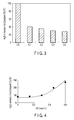
- this vehicle was made to run at a speed of 40 km/h for a fixed time to allow sulfur to be adsorbed to catalyst C1. Then, the vehicle was accelerated to 100 km/h at full throttle. Once the speed reached 100 km/h, the throttle was closed so the vehicle came to a halt and the engine was allowed to idle for a fixed time. The above measurement was also made for catalysts C2 to C5. The results are shown in FIG. 3 .
- FIG. 3 is a bar graph showing the amount of H 2 S to be emitted.
- FIG. 3 shows a cumulative amount of H 2 S emitted from each of catalysts C1 to C5 for 60 seconds after the vehicle halts, as a relative value when the value obtained using catalyst C5 is set to 100.
- Catalysts C6 to C10 were produced in the following manner. Data related to these catalysts is collected in the following Tables 3 and 4. Table 3 Catalysts Whole First part Surface Area (m 2 /L) Slurry Coating width (%) Pt ( ⁇ 10 -3 mol/L) Rh ( ⁇ 10 -3 mol/L) Ceria (mol/L) Zirconia (mol/L) Alumina (mol/L) Titania (mol/L) C6 13000 SF 50 2.5 0.20 0.3 0.42 0.54 - 5.0 0.40 0.6 0.84 1.08 C7 13000 SF 50 2.5 0.20 0.3 0.42 0.54 - 5.0 0.40 0.6 0.84 1.08 C8 13000 SF 50 2.5 0.20 0.3 0.42 0.54 - 5.0 0.40 0.6 0.84 1.08 C9 13000 SF 50 2.5 0.20 0.3 0.42 0.54 - 5.0 0.40 0.6 0.84 1.08 C10 (Comparative Example) 13000 SF 50 2.5 0.20 0.3 0.42 0.54 - 5.0 0.
- slurry SF a dinitrodiamine platinum nitric acid solution, a rhodium nitrate solution, a cerium oxide powder, a zirconium oxide powder, an alumina powder and an alumina sol were mixed to prepare a slurry.
- this slurry is referred to as "slurry SF”.
- slurry SG a dinitrodiamine platinum nitric acid solution, a rhodium nitrate solution, an alumina powder and an alumina sol were mixed to prepare a slurry.
- this slurry is referred to as "slurry SG”.
- Example 2 the same monolith honeycomb support substrate as used in Example 1 was prepared and coated with slurry SF in a range from the upstream end to 50% of the length of the substrate, followed by drying.
- slurry SG was applied to the substrate in a range from the downstream end to 50% of the length of the substrate, followed by drying.
- these coating layers were subjected to the same heat-treatment as described for the catalyst C1.
- an exhaust gas-purifying catalyst obtained in this manner is referred to as "catalyst C6".
- Each content of materials per unit volume of the catalyst in the first part which was a part corresponding to the coating layer formed using slurry SF among this catalyst C6 was as follows: platinum: 2.5 ⁇ 10 -3 mol/L; rhodium: 0.20 ⁇ 10 -3 mol/L; cerium oxide: 0.3 mol/L; zirconium oxide: 0.42 mol/L; and alumina: 0.54 mol/L.
- Each content of materials per unit volume of the catalyst in the second part which was a part corresponding to the coating layer formed using slurry SG among this catalyst C6 was as follows: platinum: 0.50 ⁇ 10 -3 mol/L; rhodium: 1.0 ⁇ 10 -3 mol/L; cerium: 0 mol/L; and alumina: 0.68 mol/L.
- the surface area of catalyst C6 per unit volume was 13000 m 2 /L.
- the content D1 of the oxygen storage material of the first part per unit volume was 0.6 mol/L.
- the content D2 of the oxygen storage material of the second part per unit volume was 0 mol/L.
- the ratio of D2 to D1 was 0.
- slurry SH a dinitrodiamine platinum nitric acid solution, a rhodium nitrate solution, a cerium oxide powder, a zirconium oxide powder, an alumina powder and an alumina sol were mixed to prepare a slurry.
- this slurry is referred to as "slurry SH”.
- catalyst C7 An exhaust gas-purifying catalyst was manufactured in the same manner as the above-explained catalyst C6 except that slurry SH was used in place of slurry SG.
- this catalyst is referred to as "catalyst C7".
- Each content of materials per unit volume of the catalyst in the first part which was a part corresponding to the coating layer formed using slurry SF among this catalyst C7 was as follows: platinum: 2.5 ⁇ 10 -3 mol/L; rhodium: 0.20 ⁇ 10 -3 mol/L; cerium oxide: 0.3 mol/L; zirconium oxide: 0.42 mol/L; and alumina: 0.54 mol/L.
- Each content of materials per unit volume of the catalyst in the second part which was a part corresponding to the coating layer formed using slurry SH among this catalyst C7 was as follows: platinum: 0.50 ⁇ 10 -3 mol/L; rhodium: 1.0 ⁇ 10 -3 mol/L; cerium oxide: 0.075 mol/L; zirconium oxide: 0.105 mol/L; and alumina: 0.60 mol/L.
- the surface area of catalyst C7 per unit volume was 13000 m 2 /L.
- the content D1 of the oxygen storage material of the first part per unit volume was 0.6 mol/L.
- the content D2 of the oxygen storage material of the second part per unit volume was 0.15 mol/L.
- the ratio of D2 to D1 was 0.25.
- a slurry was prepared in the same manner as slurry SH except that the contents of the cerium oxide powder and zirconium oxide powder were increased and the content of alumina was decreased.
- this slurry is referred to as "slurry SI”.
- catalyst C8 An exhaust gas-purifying catalyst was manufactured in the same manner as the above-explained catalyst C7 except that slurry SI was used in place of slurry SH.
- this catalyst is referred to as "catalyst C8".
- Each content of materials per unit volume of the catalyst in the first part which was a part corresponding to the coating layer formed using slurry SF among this catalyst C8 was as follows: platinum: 2.5 ⁇ 10 -3 mol/L; rhodium: 0.20 ⁇ 10 -3 mol/L; cerium oxide: 0.3 mol/L; zirconium oxide: 0.42 mol/L; and alumina: 0.54 mol/L.
- Each content of materials per unit volume of the catalyst in the second part which was a part corresponding to the coating layer formed using slurry SI among this catalyst C8 was as follows: platinum: 0.50 ⁇ 10 -3 mol/L; rhodium: 1.0 ⁇ 10 -3 mol/L; cerium oxide: 0.15 mol/L; zirconium oxide: 0.21 mol/L; and alumina: 0.52 mol/L.
- the surface area of catalyst C8 per unit volume was 13000 m 2 /L.
- the content D1 of the oxygen storage material of the first part per unit volume was 0.6 mol/L.
- the content D2 of the oxygen storage material of the second part per unit volume was 0.3 mol/L.
- the ratio of D2 to D1 was 0.5.
- a slurry was prepared in the same manner as slurry SI except that the contents of the cerium oxide powder and zirconium oxide powder were increased and the content of alumina was decreased.
- this slurry is referred to as "slurry SJ”.
- catalyst C9 An exhaust gas-purifying catalyst was manufactured in the same manner as the above-explained catalyst C7 except that slurry SJ was used in place of slurry SH.
- this catalyst is referred to as "catalyst C9".
- Each content of materials per unit volume of the catalyst in the first part which was a part corresponding to the coating layer formed using slurry SF among this catalyst C9 was as follows: platinum: 2.5 ⁇ 10 -3 mol/L; rhodium: 0.20 ⁇ 10 -3 mol/L; cerium oxide: 0.3 mol/L; zirconium oxide: 0.42 mol/L; and alumina: 0.54 mol/L.
- Each content of materials per unit volume of the catalyst in the second part which was a part corresponding to the coating layer formed using slurry SJ among this catalyst C9 was as follows: platinum: 0.50 ⁇ 10 -3 mol/L; rhodium: 1.0 ⁇ 10 -3 mol/L; cerium oxide: 0.225 mol/L; zirconium oxide: 0.315 mol/L; and alumina: 0.44 mol/L.
- the surface area of catalyst C9 per unit volume was 13000 m 2 /L.
- the content D1 of the oxygen storage material of the first part per unit volume was 0.6 mol/L.
- the content D2 of the oxygen storage material of the second part per unit volume was 0.45 mol/L.
- the ratio of D2 to D1 was 0.75.
- a slurry was prepared in the same manner as slurry SJ except that the contents of the cerium oxide powder and zirconium oxide powder were increased and the content of alumina was decreased.
- this slurry is referred to as "slurry SK".
- catalyst C10 An exhaust gas-purifying catalyst was manufactured in the same manner as the above-explained catalyst C7 except that slurry SK was used in place of slurry SH.
- this catalyst is referred to as "catalyst C10".
- Each content of materials per unit volume of the catalyst in the first part which was a part corresponding to the coating layer formed using slurry SF among this catalyst C10 was as follows: platinum: 2.5 ⁇ 10 -3 mol/L; rhodium: 0.20 ⁇ 10 -3 mol/L; cerium oxide: 0.3 mol/L; zirconium oxide: 0.42 mol/L; and alumina: 0.54 mol/L.
- Each content of materials per unit volume of the catalyst in the second part which was a part corresponding to the coating layer formed using slurry SK among this catalyst C10 was as follows: platinum: 0.50 ⁇ 10 -3 mol/L; rhodium: 1.0 ⁇ 10 -3 mol/L; cerium oxide: 0.3 mol/L; zirconium oxide: 0.42 mol/L; and alumina: 0.36 mol/L.
- the surface area of catalyst C10 per unit volume was 13000 m 2 /L.
- the content D1 of the oxygen storage material of the first part per unit volume was 0.6 mol/L.
- the content D2 of the oxygen storage material of the second part per unit volume was 0.6 mol/L.
- the ratio of D2 to D1 was 1.
- FIG. 4 is a graph showing the relation between the content D2 of the oxygen storage material per unit volume in the second part and the amount of H 2 S to be emitted.
- the amount of H 2 S to be emitted can be suppressed more significantly than in the case of using catalyst C5 by reducing the above D2 to 0.3 mol/L or less. In other words, it is found that the amount of H 2 S to be emitted is remarkably reduced by reducing the ratio D2/D1 to 0.5 or less.
- Catalysts C11 to C16 were produced in the following manner. Data related to these catalysts is collected in Tables 5 and 6. Table 5 Catalysts Whole First part Surface Area (m 2 /L) Slurry Coating width (%) Pt ( ⁇ 10 -3 mol/L) Rh ( ⁇ 10 -3 mol/L) Ceria (mol/L) Zirconia (mol/L) Alumina (mol/L) Titania (mol/L) C11 13000 SF 90 2.5 0.20 0.3 0.42 0.54 - 2.8 0.22 0.33 0.47 0.60 C12 13000 SF 85 2.5 0.20 0.3 0.42 0.54 - 2.9 0.24 0.35 0.49 0.64 C13 13000 SF 75 2.5 0.20 0.3 0.42 0.54 - 3.3 0.27 0.40 0.56 0.72 C14 13000 SF 25 2.5 0.20 0.3 0.42 0.54 - 10 0.80 1.20 1.68 2.16 C15 13000 SF 15 2.5 0.20 0.3 0.42 0.54 - 16.7 1.33 2.00 2.80 3.60 C16
- An exhaust gas-purifying catalyst was produced in the same manner as catalyst C6 except that slurry SF was applied to the substrate in a range from the upstream end to 90% of the length of the substrate instead of applying slurry SF to the substrate in a range from the upstream end to 50% of the length of the substrate, and slurry SG was applied to the substrate in a range from the downstream end to 10% of the length of the substrate instead of applying slurry SG to the substrate in a range from the downstream end to 50% of the length of the substrate.
- this catalyst is referred to as "catalyst C11".
- the content D1 of the oxygen storage material per unit volume of the first part corresponding to the coating layer formed using slurry SF among this catalyst C11 was 0.33 mol/L.
- the content D2 of the oxygen storage material per unit volume of the second part corresponding to the coating layer formed using slurry SG among this catalyst C11 was 0 mol/L.
- the surface area of catalyst C11 per unit volume was 13000 m 2 /L.
- An exhaust gas-purifying catalyst was produced in the same manner as catalyst C6 except that slurry SF was applied to the substrate in a range from the upstream end to 85% of the length of the substrate instead of applying slurry SF to the substrate in a range from the upstream end to 50% of the length of the substrate, and slurry SG was applied to the substrate in a range from the downstream end to 15% of the length of the substrate instead of applying slurry SG to the substrate in a range from the downstream end to 50% of the length of the substrate.
- this catalyst is referred to as "catalyst C12".
- the content D1 of the oxygen storage material per unit volume of the first part corresponding to the coating layer formed using slurry SF among this catalyst C12 was 0.35 mol/L.
- the content D2 of the oxygen storage material per unit volume of the second part corresponding to the coating layer formed using slurry SG among this catalyst C12 was 0 mol/L.
- the surface area of catalyst C12 per unit volume was 13000 m 2 /L.
- An exhaust gas-purifying catalyst was produced in the same manner as catalyst C6 except that slurry SF was applied to the substrate in a range from the upstream end to 75% of the length of the substrate instead of applying slurry SF to the substrate in a range from the upstream end to 50% of the length of the substrate, and slurry SG was applied to the substrate in a range from the downstream end to 25% of the length of the substrate instead of applying slurry SG to the substrate in a range from the downstream end to 50% of the length of the substrate.
- this catalyst is referred to as "catalyst C13".
- the content D1 of the oxygen storage material per unit volume of the first part corresponding to the coating layer formed using slurry SF among this catalyst C13 was 0.40 mol/L.
- the content D2 of the oxygen storage material per unit volume of the second part corresponding to the coating layer formed using slurry SG among this catalyst C13 was 0 mol/L.
- the surface area of catalyst C13 per unit volume was 13000 m 2 /L.
- An exhaust gas-purifying catalyst was produced in the same manner as catalyst C6 except that slurry SF was applied to the substrate in a range from the upstream end to 25% of the length of the substrate instead of applying slurry SF to the substrate in a range from the upstream end to 50% of the length of the substrate, and slurry SG was applied to the substrate in a range from the downstream end to 75% of the length of the substrate instead of applying slurry SG to the substrate in a range from the downstream end to 50% of the length of the substrate.
- this catalyst is referred to as "catalyst C14".
- the content D1 of the oxygen storage material per unit volume of the first part corresponding to the coating layer formed using slurry SF among this catalyst C14 was 1.2 mol/L.
- the content D2 of the oxygen storage material per unit volume of the second part corresponding to the coating layer formed using slurry SG among this catalyst C14 was 0 mol/L.
- the surface area of catalyst C14 per unit volume was 13000 m 2 /L.
- An exhaust gas-purifying catalyst was produced in the same manner as catalyst C6 except that slurry SF was applied to the substrate in a range from the upstream end to 15% of the length of the substrate instead of applying slurry SF to the substrate in a range from the upstream end to 50% of the length of the substrate, and slurry SG was applied to the substrate in a range from the downstream end to 85% of the length of the substrate instead of applying slurry SG to the substrate in a range from the downstream end to 50% of the length of the substrate.
- this catalyst is referred to as "catalyst C15".
- the content D1 of the oxygen storage material per unit volume of the first part corresponding to the coating layer formed using slurry SF among this catalyst C15 was 2.0 mol/L.
- the content D2 of the oxygen storage material per unit volume of the second part corresponding to the coating layer formed using slurry SG among this catalyst C15 was 0 mol/L.
- the surface area of catalyst C15 per unit volume was 13000 m 2 /L.
- An exhaust gas-purifying catalyst was produced in the same manner as catalyst C6 except that slurry SF was applied to the substrate in a range from the upstream end to 10% of the length of the substrate instead of applying slurry SF to the substrate in a range from the upstream end to 50% of the length of the substrate, and slurry SG was applied to the substrate in a range from the downstream end to 90% of the length of the substrate instead of applying slurry SG to the substrate in a range from the downstream end to 50% of the length of the substrate.
- this catalyst is referred to as "catalyst C16".
- the content D1 of the oxygen storage material per unit volume of the first part corresponding to the coating layer formed using slurry SF among this catalyst C16 was 3.0 mol/L.
- the content D2 of the oxygen storage material per unit volume of the second part corresponding to the coating layer formed using slurry SG among this catalyst C16 was 0 mol/L.
- the surface area of catalyst C16 per unit volume was 13000 m 2 /L.
- each of these catalysts was set to a vehicle mounted with a straight-four 2.4-liter engine. Then, this vehicle was made to run according to the LA #4 (hot) mode to measure the amount of NO x to be emitted.
- FIG. 5 is a graph showing the relation between the coating widths of the first and second parts and the amounts of H 2 S and NO x to be emitted.
- the amount of H 2 S to be emitted is reduced when the coating width of the second part is increased. This reason is inferred to be that the adsorption of sulfur to the catalyst layer is more suppressed with increase in the coating width of the second part which is low in the content of the oxygen storage material. On the contrary, when the coating width of the second part is decreased, the amount of NO x to be emitted is reduced. This reason is inferred to be that the oxygen storage ability of the catalyst layer is more improved with increase in the coating width of the first part which is high in the content of the oxygen storage material.
- Catalysts C17 to C23 were produced in the following manner. Data related to these catalysts is collected in Tables 7 and 8. Table 7 Catalysts Whole First part Surface Area (m 2 /L) Slurry Coating width (%) Pt ( ⁇ 10 -3 mol/L) Rh ( ⁇ 10 -3 mol/L) Ceria (mol/L) Zirconia (mol/L) Alumina (mol/L) Titania (mol/L) C17 1400 SF 50 2.5 0.20 0.3 0.42 0.54 - 5.0 0.40 0.6 0.84 1.08 C18 3400 SF 50 2.5 0.20 0.3 0.42 0.54 - 5.0 0.40 0.6 0.84 1.08 C19 5000 SF 50 2.5 0.20 0.3 0.42 0.54 - 5.0 0.40 0.6 0.84 1.08 C20 6800 SF 50 2.5 0.20 0.3 0.42 0.54 - 5.0 0.40 0.6 0.84 1.08 C21 20000 SF 50 2.5 0.20 0.3 0.42 0.54 - 5.0 0.40 0.6 0.84 1.08 C
- An exhaust gas-purifying catalyst having a surface area of 1400 m 2 /L per unit volume was produced in the same manner as the abovementioned catalyst C6 except that a powder having a smaller specific surface area was used as the powder contained in the slurries SF and SG.
- this catalyst is referred to as "catalyst C17".
- An exhaust gas-purifying catalyst having a surface area of 3400 m 2 /L per unit volume was produced in the same manner as the abovementioned catalyst C6 except that a powder having a smaller specific surface area was used as the powder contained in the slurries SF and SG.
- this catalyst is referred to as "catalyst C18".
- An exhaust gas-purifying catalyst having a surface area of 5000 m 2 /L per unit volume was produced in the same manner as the abovementioned catalyst C6 except that a powder having a smaller specific surface area was used as the powder contained in the slurries SF and SG.
- this catalyst is referred to as "catalyst C19".
- An exhaust gas-purifying catalyst having a surface area of 6800 m 2 /L per unit volume was produced in the same manner as the abovementioned catalyst C6 except that a powder having a smaller specific surface area was used as the powder contained in the slurries SF and SG.
- this catalyst is referred to as "catalyst C20".
- An exhaust gas-purifying catalyst having a surface area of 20000 m 2 /L per unit volume was produced in the same manner as the abovementioned catalyst C6 except that a powder having a larger specific surface area was used as the powder contained in the slurries SF and SG.
- this catalyst is referred to as
- An exhaust gas-purifying catalyst having a surface area of 23000 m 2 /L per unit volume was produced in the same manner as the abovementioned catalyst C6 except that a powder having a larger specific surface area was used as the powder contained in the slurries SF and SG.
- this catalyst is referred to as
- An exhaust gas-purifying catalyst having a surface area of 26000 m 2 /L per unit volume was produced in the same manner as the abovementioned catalyst C6 except that a powder having a larger specific surface area was used as the powder contained in the slurries SF and SG.
- this catalyst is referred to as
- FIG. 6 is a graph showing the relation between the surface area of the catalyst per unit volume and the amount of H 2 S and NO x to be emitted.
- the amount of H 2 S to be emitted is reduced with decrease in the surface area per unit volume whereas the amount of NO x to be emitted is reduced with increase in the surface area per unit volume.
- the surface area per unit volume is designed to be, for example, in a range of 5000 to 23000 m 2 /L, a reduction in the amount of H 2 S to be emitted and a reduction in the amount of NO x to be emitted can be both attained at the same time.
- the surface area per unit volume is designed to be in a range of 5000 to 16000 m 2 /L, especially excellent performance is exhibited.
- Catalysts C24 to C28 were produced in the following manner. Data related to these catalysts is collected in Tables 9 and 10.
- Table 9 Catalysts First part Slurry Coating width (%) Pt ( ⁇ 10 -3 mol/L) Rh ( ⁇ 10 -3 mol/L) Ceria (mol/L) Zirconia (mol/L) Alumina (mol/L) Titania (mol/L) C24 SA 50 2.5 0.20 0.17 0.34 0.54 - 5.0 0.40 0.34 0.68 1.08 C25 SA 50 2.5 0.20 0.17 0.34 0.54 - 5.0 0.40 0.34 0.68 1.08 C26 SA 50 2.5 0.20 0.17 0.34 0.54 - 5.0 0.40 0.34 0.68 1.08 C27 SA 50 2.5 0.20 0.17 0.34 0.54 - 5.0 0.40 0.34 0.68 1.08 C28 SA 50 2.5 0.20 0.17 0.34 0.54 - 5.0 0.40 0.34 0.68 1.08 C28 SA 50 2.5 0.20 0.17 0.34 0.54 - 5.0 0.40 0.34 0.68 1.
- An exhaust gas-purifying catalyst provided with the second part having a surface area of 13000 m 2 /L per unit volume was produced in the same manner as the aforementioned catalyst C1 except that the specific surface area of the powder contained in slurry SB was changed.
- this catalyst is referred to as "catalyst C24".
- An exhaust gas-purifying catalyst provided with the second part having a surface area of 10000 m 2 /L per unit volume was produced in the same manner as the aforementioned catalyst C1 except that the specific surface area of the powder contained in slurry SB was changed.
- this catalyst is referred to as "catalyst C25".
- An exhaust gas-purifying catalyst provided with the second part having a surface area of 7500 m 2 /L per unit volume was produced in the same manner as the aforementioned catalyst C1 except that the specific surface area of the powder contained in slurry SB was changed.
- this catalyst is referred to as "catalyst C26".
- An exhaust gas-purifying catalyst provided with the second part having a surface area of 5000 m 2 /L per unit volume was produced in the same manner as the aforementioned catalyst C1 except that the specific surface area of the powder contained in slurry SB was changed.
- this catalyst is referred to as "catalyst C27".
- An exhaust gas-purifying catalyst provided with the second part having a surface area of 4000 m 2 /L per unit volume was produced in the same manner as the aforementioned catalyst C1 except that the specific surface area of the powder contained in slurry SB was changed.
- this catalyst is referred to as "catalyst C28".
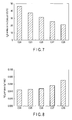
- FIG. 7 is a bar graph showing the amount of H 2 S to be emitted.
- FIG. 8 is a bar graph showing the amount of NO x to be emitted.
- FIG. 7 and FIG. 8 each show the relation between the surface area of the second part of the catalyst per unit volume and the amounts of H 2 S and NO X to be emitted.
- Table 11 and FIG. 7 respectively show the cumulative amount of H 2 S emitted from catalysts C24 to C28 for 60 seconds after the vehicle halts, as a relative value when the value obtained using catalyst C5 is set to 100.
- Catalysts C29 to C32 were produced in the following manner. Data related to these catalysts is collected in Tables 12 and 13.
- Table 12 Catalysts Whole First part Surface Area (m 2 /L) Slurry Coating width (%) Pt ( ⁇ 10 -3 mol/L) Rh ( ⁇ 10 -3 mol/L) Ceria (mol/L) Zirconia (mol/L) Alumina (mol/L) Titania (mol/L) C29 13000 SL 50 3.0 0.40 0.17 0.34 0.54 - 6.0 0.80 0.34 0.68 1.08 C30 13000 SN 50 3.0 0.60 0.17 0.34 0.54 - 6.0 1.20 0.34 0.68 1.08 C31 13000 SP 50 3.0 0.90 0.17 0.34 0.54 - 6.0 1.80 0.34 0.68 1.08 C32 13000 SR 50 3.0 1.0 0.17 0.34 0.54 - 6.0 2.00 0.34 0.68 1.08 Table 13 Catalysts Second Part Slurry Coating width (%) Pt ( ⁇ 10 -3
- a slurry was prepared in the same manner as slurry SA except that the contents of platinum and rhodium were increased.
- this slurry is referred to as "slurry SL”.
- a slurry was prepared in the same manner as slurry SB except that the dinitrodiamine platinum nitrate solution was omitted and the content of rhodium was decreased.
- this slurry is referred to as "slurry SM”.
- Catalyst C29 An exhaust gas-purifying catalyst was produced in the same manner as catalyst C1 except that slurry SL was used instead of slurry SA and slurry SM was used instead of slurry SB.
- this catalyst is referred to as "catalyst C29".
- Each content of materials per unit volume of the catalyst in the first part which was a part corresponding to the coating layer formed using slurry SL among this catalyst C29 was as follows: platinum: 3.0 ⁇ 10 -3 mol/L; rhodium: 0.40 ⁇ 10 -3 mol/L; cerium oxide: 0.17 mol/L; zirconium oxide: 0.34 mol/L; and alumina: 0.54 mol/L.
- Each content of materials per unit volume of the catalyst in the second part which was a part corresponding to the coating layer formed using slurry SM among this catalyst C29 was as follows: rhodium: 0.80 ⁇ 10 -3 mol/L; and alumina: 0.68 mol/L.
- the surface area of catalyst C29 per unit volume was 13000 m 2 /L.
- the molar ratio of content of precious metals per unit volume in first part to content of precious metals per unit volume in second part was 4.25.
- a slurry was prepared in the same manner as slurry SL except that the content of rhodium was increased.
- this slurry is referred to as "slurry SN”.
- a slurry was prepared in the same manner as slurry SM except that the content of rhodium was decreased.
- this slurry is referred to as "slurry SO”.
- Catalyst C30 An exhaust gas-purifying catalyst was produced in the same manner as catalyst C29 except that slurry SN was used instead of slurry SL and slurry SO was used instead of slurry SM.
- this catalyst is referred to as "catalyst C30".
- Each content of materials per unit volume of the catalyst in the first part which was a part corresponding to the coating layer formed using slurry SN among this catalyst C30 was as follows: platinum: 3.0 ⁇ 10 -3 mol/L; rhodium: 0.60 ⁇ 10 -3 mol/L; cerium oxide: 0.17 mol/L; zirconium oxide: 0.34 mol/L; and alumina: 0.54 mol/L.
- Each content of materials per unit volume of the catalyst in the second part which was a part corresponding to the coating layer formed using slurry SO among this catalyst C30 was as follows: rhodium: 0.60 ⁇ 10 -3 mol/L; and alumina: 0.68 mol/L.
- the surface area of catalyst C30 per unit volume was 13000 m 2 /L.
- the molar ratio of content of precious metals per unit volume in first part to content of precious metals per unit volume in second part was 6.0.
- a slurry was prepared in the same manner as slurry SN except that the content of rhodium was increased.
- this slurry is referred to as "slurry SP”.
- slurry SQ A slurry was prepared in the same manner as slurry SO except that the content of rhodium was decreased.
- this slurry is referred to as "slurry SQ”.
- Catalyst C31 An exhaust gas-purifying catalyst was produced in the same manner as catalyst C30 except that slurry SP was used instead of slurry SN and slurry SQ was used instead of slurry SO.
- this catalyst is referred to as "catalyst C31".
- Each content of materials per unit volume of the catalyst in the first part which was a part corresponding to the coating layer formed using slurry SP among this catalyst C31 was as follows: platinum: 3.0 ⁇ 10 -3 mol/L; rhodium: 0.90 ⁇ 10 -3 mol/L; cerium oxide: 0.17 mol/L; zirconium oxide: 0.34 mol/L; and alumina: 0.54 mol/L.
- Each content of materials per unit volume of the catalyst in the second part which was a part corresponding to the coating layer formed using slurry SQ among this catalyst C31 was as follows: rhodium: 0.30 ⁇ 10 -3 mol/L; and alumina: 0.68 mol/L.
- the surface area of catalyst C31 per unit volume was 13000 m 2 /L.
- the molar ratio of content of precious metals per unit volume in first part to content of precious metals per unit volume in second part was 13.
- a slurry was prepared in the same manner as slurry SP except that the content of rhodium was increased.
- this slurry is referred to as "slurry SR”.
- a slurry was prepared in the same manner as slurry SQ except that the content of rhodium was decreased.
- this slurry is referred to as "slurry SS”.
- Catalyst C32 An exhaust gas-purifying catalyst was produced in the same manner as catalyst C31 except that slurry SR was used instead of slurry SP and slurry SS was used instead of slurry SQ.
- this catalyst is referred to as "catalyst C32".
- Each content of materials per unit volume of the catalyst in the first part which was a part corresponding to the coating layer formed using slurry SR among this catalyst C32 was as follows: platinum: 3.0 ⁇ 10 -3 mol/L; rhodium: 1.0 ⁇ 10 -3 mol/L; cerium oxide: 0.17 mol/L; zirconium oxide: 0.34 mol/L; and alumina: 0.54 mol/L.
- Each content of materials per unit volume of the catalyst in the second part which was a part corresponding to the coating layer formed using slurry SS among this catalyst C32 was as follows: rhodium: 0.20 ⁇ 10 -3 mol/L; and alumina: 0.68 mol/L.
- the surface area of catalyst C32 per unit volume was 13000 m 2 /L.
- the molar ratio of content of precious metals per unit volume in first part to content of precious metals per unit volume in second part was 20.
- FIG. 9 is a bar graph showing the amount of NO x to be emitted.
- FIG. 9 shows the relation between the molar ratio of the content of precious metals in the first part to the content of precious metals in the second part and the amount of NO x to be emitted.
- Catalysts C33 to C39 were produced in the following manner. Data related to these catalysts is collected in Tables 15 and 16. Table 15 Catalysts Whole First Part Surface Area (m 2 /L) Slurry Coating width (%) Pt ( ⁇ 10 -3 mol/L) Rh ( ⁇ 10 -3 mol/L) Ceria (mol/L) Lanthanum oxide (mol%) Yttrium oxide (mol%) Zirconia (mol/L) Alumina (mol/L) Titania (mol/L) C33 13000 ST 50 2.5 0.20 0.03 - - 0.37 0.54 - 5.0 0.40 0.06 0.74 1.08 C34 13000 SU 50 2.5 0.20 0.06 - - 0.33 0.54 - 5.0 0.40 0.12 0.66 1.08 C35 13000 SV 50 2.5 0.20 0.06 - - 0.28 0.54 - 5.0 0.40 0.12 0.56 1.08 C36 13000 SW 50 2.5 0.20 0.12 - - 0.24 0.54 - 5.0 0.40 0.24 0.48 1.
- a slurry was prepared in the same manner as slurry SA except that the powder of composite oxide of cerium oxide and zirconium oxide was used instead of cerium oxide powder and zirconium oxide powder.
- this slurry is referred to as "slurry ST”.
- Catalyst C33 An exhaust gas-purifying catalyst was produced in the same manner as catalyst C1 except that slurry ST was used instead of slurry SA.
- this catalyst is referred to as "catalyst C33".
- Each content of materials per unit volume of the catalyst in the first part which was a part corresponding to the coating layer formed using slurry ST among this catalyst C33 was as follows: platinum: 2.5 ⁇ 10 -3 mol/L; rhodium: 0.20 ⁇ 10 -3 mol/L; cerium oxide: 0.03 mol/L; zirconium oxide: 0.37 mol/L; and alumina: 0.54 mol/L.
- Each content of materials per unit volume of the catalyst in the second part which was a part corresponding to the coating layer formed using slurry SB among this catalyst C33 was as follows: platinum: 0.5 ⁇ 10 -3 mol/L; rhodium: 1.0 ⁇ 10 -3 mol/L; and alumina: 0.68 mol/L.
- the surface area of catalyst C33 per unit volume was 13000 m 2 /L.
- the molar ratio of zirconium oxide to cerium oxide in the aforementioned composite oxide contained in the first part was 12.
- a slurry was prepared in the same manner as slurry ST except that the composite oxide higher in the content of cerium was used.
- this slurry is referred to as "slurry SU”.
- Catalyst C34 An exhaust gas-purifying catalyst was produced in the same manner as catalyst C33 except that slurry SU was used instead of slurry ST.
- this catalyst is referred to as "catalyst C34".
- Each content of materials per unit volume of the catalyst in the first part which was a part corresponding to the coating layer formed using slurry SU among this catalyst C34 was as follows: platinum: 2.5 ⁇ 10 -3 mol/L; rhodium: 0.20 ⁇ 10 -3 mol/L; cerium oxide: 0.06 mol/L; zirconium oxide: 0.33 mol/L; and alumina: 0.54 mol/L.
- Each content of materials per unit volume of the catalyst in the second part which was a part corresponding to the coating layer formed using slurry SB among this catalyst C34 was as follows: platinum: 0.5 ⁇ 10 -3 mol/L; rhodium: 1.0 ⁇ 10 -3 mol/L; and alumina: 0.68 mol/L.
- the surface area of catalyst C34 per unit volume was 13000 m 2 /L.
- the molar ratio of zirconium oxide to cerium oxide in the aforementioned composite oxide contained in the first part was 5.5.
- a slurry was prepared in the same manner as slurry SU except that the composite oxide higher in the content of cerium was used.
- this slurry is referred to as "slurry SV".
- Catalyst C35 An exhaust gas-purifying catalyst was produced in the same manner as catalyst C34 except that slurry SV was used instead of slurry SU.
- this catalyst is referred to as "catalyst C35".
- Each content of materials per unit volume of the catalyst in the first part which was a part corresponding to the coating layer formed using slurry SV among this catalyst C35 was as follows: platinum: 2.5 ⁇ 10 -3 mol/L; rhodium: 0.20 ⁇ 10 -3 mol/L; cerium oxide: 0.09 mol/L; zirconium oxide: 0.28 mol/L; and alumina: 0.54 mol/L.
- Each content of materials per unit volume of the catalyst in the second part which was a part corresponding to the coating layer formed using slurry SB among this catalyst C35 was as follows: platinum: 0.5 ⁇ 10 -3 mol/L; rhodium: 1.0 ⁇ 10 -3 mol/L; and alumina: 0.68 mol/L.
- the surface area of catalyst C35 per unit volume was 13000 m 2 /L.
- the molar ratio of zirconium oxide to cerium oxide in the aforementioned composite oxide contained in the first part was 3.1.
- a slurry was prepared in the same manner as slurry SV except that the composite oxide higher in the content of cerium was used.
- this slurry is referred to as "slurry SW”.
- Catalyst C36 An exhaust gas-purifying catalyst was produced in the same manner as catalyst C35 except that slurry SW was used instead of slurry SV.
- this catalyst is referred to as "catalyst C36".
- Each content of materials per unit volume of the catalyst in the first part which was a part corresponding to the coating layer formed using slurry SW among this catalyst C36 was as follows: platinum: 2.5 ⁇ 10 -3 mol/L; rhodium: 0.20 ⁇ 10 -3 mol/L; cerium oxide: 0.12 mol/L; zirconium oxide: 0.24 mol/L; and alumina: 0.54 mol/L.
- Each content of materials per unit volume of the catalyst in the second part which was a part corresponding to the coating layer formed using slurry SB among this catalyst C36 was as follows: platinum: 0.5 ⁇ 10 -3 mol/L; rhodium: 1.0 ⁇ 10 -3 mol/L; and alumina: 0.68 mol/L.
- the surface area of catalyst C36 per unit volume was 13000 m 2 /L.
- the molar ratio of zirconium oxide to cerium oxide in the aforementioned composite oxide contained in the first part was 2.0.
- slurry SX A slurry was prepared in the same manner as slurry SW except that the composite oxide higher in the content of cerium was used.
- this slurry is referred to as "slurry SX”.
- Catalyst C37 An exhaust gas-purifying catalyst was produced in the same manner as catalyst C36 except that slurry SX was used instead of slurry SW. Hereinafter, this catalyst is referred to as "catalyst C37".
- Each content of materials per unit volume of the catalyst in the first part which was a part corresponding to the coating layer formed using slurry SX among this catalyst C37 was as follows: platinum: 2.5 ⁇ 10 -3 mol/L; rhodium: 0.20 ⁇ 10 -3 mol/L; cerium oxide: 0.15 mol/L; zirconium oxide: 0.20 mol/L; and alumina: 0.54 mol/L.
- Each content of materials per unit volume of the catalyst in the second part which was a part corresponding to the coating layer formed using slurry SB among this catalyst C37 was as follows: platinum: 0.5 ⁇ 10 -3 mol/L; rhodium: 1.0 ⁇ 10 -3 mol/L; and alumina: 0.68 mol/L.
- the surface area of catalyst C37 per unit volume was 13000 m 2 /L.
- the molar ratio of zirconium oxide to cerium oxide in the aforementioned composite oxide contained in the first part was 1.3.
- a slurry was prepared in the same manner as slurry SV except that lanthanum oxide and yttrium oxide were added.
- this slurry is referred to as "slurry SY”.
- catalyst C38 An exhaust gas-purifying catalyst was produced in the same manner as catalyst C35 except that slurry SY was used instead of slurry SV.
- this catalyst is referred to as "catalyst C38".
- Each content of materials per unit volume of the catalyst in the first part which was a part corresponding to the coating layer formed using slurry SY among this catalyst C38 was as follows: platinum: 2.5 ⁇ 10 -3 mol/L; rhodium: 0.20 ⁇ 10 -3 mol/L; cerium oxide: 0.09 mol/L; zirconium oxide: 0.28 mol/L; and alumina: 0.54 mol/L.
- the content of lanthanum oxide was 2 mol% based on the content of the composite oxide of cerium oxide and zirconium oxide.
- the content of yttrium oxide was 3 mol% based on the content of the composite oxide of cerium oxide and zirconium oxide.
- Each content of materials per unit volume of the catalyst in the second part which was a part corresponding to the coating layer formed using slurry SB among this catalyst C38 was as follows: platinum: 0.5 ⁇ 10 -3 mol/L; rhodium: 1.0 ⁇ 10 -3 mol/L; and alumina: 0.68 mol/L.
- the surface area of catalyst C38 per unit volume was 13000 m 2 /L.
- the molar ratio of zirconium oxide to cerium oxide in the aforementioned composite oxide contained in the first part was 3.1.
- a slurry was prepared in the same manner as slurry SA except that the powder of composite oxide of cerium oxide and zirconium oxide was used instead of cerium oxide powder and zirconium oxide powder.
- this slurry is referred to as "slurry SZ”.
- Catalyst C39 An exhaust gas-purifying catalyst was produced in the same manner as catalyst C1 except that slurry SZ was used instead of slurry SA.
- this catalyst is referred to as "catalyst C39".
- Each content of materials per unit volume of the catalyst in the first part which was a part corresponding to the coating layer formed using slurry SZ among this catalyst C39 was as follows: platinum: 2.5 ⁇ 10 -3 mol/L; rhodium: 0.20 ⁇ 10 -3 mol/L; cerium oxide: 0.17 mol/L; zirconium oxide: 0.34 mol/L; and alumina: 0.54 mol/L.
- Each content of materials per unit volume of the catalyst in the second part which was a part corresponding to the coating layer formed using slurry SB among this catalyst C39 was as follows: platinum: 0.5 ⁇ 10 -3 mol/L; rhodium: 1.0 ⁇ 10 -3 mol/L; and alumina: 0.68 mol/L.
- the surface area of catalyst C39 per unit volume was 13000 m 2 /L.
- the molar ratio of zirconium oxide to cerium oxide in the aforementioned composite oxide contained in the first part was 2.0.
- FIG. 10 is a bar graph showing the amount of NO x to be emitted.
- FIG. 10 shows the relation between the composition of the first part of the catalyst and the amount of NO x to be emitted.
- the first part further comprises lanthanum oxide and yttrium oxide.
Landscapes
- Engineering & Computer Science (AREA)
- Chemical & Material Sciences (AREA)
- Chemical Kinetics & Catalysis (AREA)
- Combustion & Propulsion (AREA)
- Mechanical Engineering (AREA)
- Organic Chemistry (AREA)
- Health & Medical Sciences (AREA)
- General Engineering & Computer Science (AREA)
- Materials Engineering (AREA)
- Oil, Petroleum & Natural Gas (AREA)
- General Chemical & Material Sciences (AREA)
- Analytical Chemistry (AREA)
- Environmental & Geological Engineering (AREA)
- Biomedical Technology (AREA)
- Emergency Medicine (AREA)
- Catalysts (AREA)
- Exhaust Gas Treatment By Means Of Catalyst (AREA)
- Exhaust Gas After Treatment (AREA)
Abstract
Description
- The present invention relates to an exhaust gas-purifying catalyst.
- In recent years, exhaust gas regulations for automobiles and the like have been enforced. To cope with these regulations, various exhaust gas-purifying catalysts have been developed which are configured to remove nitrogen oxides (NOx) and the like in exhaust gas more efficiently. For example,
Patent Document 1 discloses an exhaust gas-purifying catalyst containing a support containing cerium oxide, and a precious metal supported by this support. The cerium oxide has high oxygen storage capability and is known to be a component effective to improve the performance of an exhaust gas-purifying catalyst. - These catalysts, however, have the problem that they tend to emit hydrogen sulfide (H2S) which is to be a cause of unacceptable odors in the course of purifying exhaust gas. In light of this, exhaust gas-purifying catalysts containing nickel (Ni) have been proposed as catalysts that decrease the emission of H2S (for example, refer to Patent Document 2).
- However, Ni is specified as an environmental load substance in many countries and districts. Therefore, exhaust gas-purifying catalysts containing a relatively large amount of Ni have come to be unusable.
-
- Patent Document 1: Jpn. Pat. Appln. KOKAI Publication No.
8-155302 - Patent Document 2: European Patent Publication No.
244127 - It is an object of the present invention to provide an exhaust gas-purifying catalyst whose emission of H2S being suppressed while having a satisfactory exhaust gas purification performance even without large amount of Ni.
- According to one aspect of the present invention, there is provided an exhaust gas-purifying catalyst comprising: a substrate provided with one or more through-holes through which exhaust gas flows; and a catalyst layer supported by the substrate and containing precious metals and an oxygen storage material, the exhaust gas-purifying catalyst comprising a first part to which the exhaust gas is supplied, and a second part to which the exhaust gas having passed through the first part is supplied and is smaller in the content of the oxygen storage material per unit volume than the first part.
-
-
FIG. 1 is a schematic view showing an exhaust gas-purifying catalyst according to an embodiment of the present invention. -
FIG. 2 is an enlarged sectional view showing a part of the exhaust gas-purifying catalyst shown inFIG. 1 . -
FIG. 3 is a bar graph showing the amount of H2S to be emitted. -
FIG. 4 is a graph showing the relation between the content D2 of the oxygen storage material per unit volume in the second part and the amount of H2S to be emitted. -
FIG. 5 is a graph showing the relation between the coating widths of the first and second parts and the amounts of H2S and NOx to be emitted. -
FIG. 6 is a graph showing the relation between the surface area of the catalyst per unit volume and the amount of H2S and NOx to be emitted. -
FIG. 7 is a bar graph showing the amount of H2S to be emitted. -
FIG. 8 is a bar graph showing the amount of NOx to be emitted. -
FIG. 9 is a bar graph showing the amount of NOx to be emitted. -
FIG. 10 is a bar graph showing the amount of NOx to be emitted. - An embodiment of the present invention will be explained below.
- The inventors of the present invention have found in the course of making studies concerning the cause of generation of H2S and, particularly, the cause of generation of H2S after a vehicle halts, that there is a difference in the cooling speeds of the catalyst depending on the positions therein.
- First, an exhaust gas-purifying catalyst comprising a catalyst layer uniformly containing a precious metal and cerium oxide was prepared. Then, this catalyst was mounted on a vehicle and the operational condition was changed while measuring the temperature of each position at distances of 0, 16, 33, 50, 67 and 83% of the overall length from the upstream end of the substrate. Specifically, first the vehicle was made to run at a speed of about 40 km/h. At this time, the temperature at the upstream end of the catalyst was about 400°C. Then, the vehicle was made to accelerate from a standstill to about 100 km/h at full throttle. The vehicle was then halted and allowed to idle.
- As a result, no significant difference was observed between the temperatures of the above positions during a period until the speed of the vehicle reached about 100 km/h. However, it was clarified that the temperature was dropped more scarcely in the vicinity of the downstream end of the catalyst than in the vicinity of the upstream end of the catalyst during the subsequent deceleration period and after the vehicle halted. It was also found that, in particular, the time during which the temperature was kept at 500°C or more was much longer in the vicinity of the downstream end of the catalyst than in the vicinity of the upstream end of the catalyst.
- The inventors of the present invention made further studies as to the characteristics of each component of the catalyst and also found that an oxygen storage material among the catalyst components participated in the adsorption and release of H2S. Though its details have not been clarified, the following mechanism is considered.
- Oxygen storage materials such as cerium oxide tend to react with sulfur components such as SO2 in exhaust gas to produce compounds such as Ce(SO4)2 in a low-temperature and oxidizing atmosphere (for example, in normal running). That is, the oxygen storage materials tend to adsorb sulfur components in this circumstance.
- In a high-temperature and reducing atmosphere (for example, at the time of high-speed running or grading), on the other hand, SO2 or H2S is easily generated by a reducing reaction of the adsorbed sulfur components. That is, in this condition, desorption of sulfur components, in particular emission of H2S, easily takes place. Particularly, when the temperature of the catalyst is about 500°C or more, the emission of H2S is prominent and this H2S is a main cause of offensive odors.
- The structures mentioned below are adopted based on the above finding.
-
FIG. 1 is a schematic view showing an exhaust gas-purifying catalyst according to an embodiment of the present invention.FIG. 2 is an enlarged sectional view showing a part of the exhaust gas-purifying catalyst shown inFIG. 1 . - The exhaust gas-purifying
catalyst 1 contains asubstrate 10 formed with one or more through-holes through which exhaust gas flows and acatalyst layer 20 supported by thesubstrate 10. - The
catalyst layer 20 contains a support and a precious metal supported by the support. The support serves to increase the specific surface area of the precious metal and also to dissipate the heat produced by the reaction to thereby limit the sintering of the precious metal. The support contains an oxygen storage material. The oxygen storage material serves to absorb and release oxygen in exhaust gas to thereby reduce a variation in the air/fuel ratio in the exhaust gas. - The precious metal serves to catalyze an exhaust purification reaction.
- Note that the
catalyst layer 20 may have a monolayer structure or a multilayer structure. In the latter case, thecatalyst layer 20 may contain a layer containing no precious metal. - The exhaust gas-purifying
catalyst 1 contains afirst part 100 and asecond part 200 which are different from each other in the content of the oxygen storage material per unit volume. Thefirst part 100 is a part to which exhaust gas is supplied ahead of thesecond part 200. Thesecond part 200 is a part to which exhaust gas having passed through thefirst part 100 is supplied.FIG. 1 shows, as an example, the case where the exhaust gas-purifyingcatalyst 1 contains only thefirst part 100 corresponding to the upstream part of the exhaust gas-purifyingcatalyst 1 and thesecond part 200 corresponding to the downstream part of the exhaust gas-purifyingcatalyst 1. Thefirst part 100 and thesecond part 200 have almost the same structure except that the both differ from each other in the content of the oxygen storage material per unit volume. - In the
first part 100, thecatalyst layer 20 contains a support and a precious metal supported by the support. In thefirst part 100, the support is an oxygen storage material, or a mixture or a composite oxide of the oxygen storage material and other oxides. - In the
second part 200, thecatalyst layer 20 contains a support and a precious metal supported by the support. In thissecond part 200, this support is oxides other than an oxygen storage material, or a mixture or a composite oxide of the oxide other than an oxygen storage material and an oxygen storage material. As mentioned above, the content D2 of the oxygen storage material per unit volume in thesecond part 200 is smaller than the content D1 of the oxygen storage material per unit volume in thefirst part 100. - The
catalyst layer 20 may contain no oxygen storage material in thesecond part 200. Alternatively, thecatalyst layer 20 may contain the oxygen storage material in both the first andsecond parts - As mentioned above, the emission of H2S becomes prominent when the exhaust gas is reducing gas of high temperature, for example, 500°C or more. The temperature of the downstream part of the exhaust gas-purifying catalyst is dropped more scarcely than that of the upstream part of the exhaust gas-purifying catalyst. Therefore, H2S is considered to be mainly produced at the downstream part.
- As mentioned above, the content D2 of the oxygen storage material of the
second part 200 is smaller than the content D1 of the oxygen storage material of thefirst part 100 in the exhaust gas-purifying catalyst 1. Therefore, in the exhaust gas-purifying catalyst 1, the amount of sulfur components adsorbed to thecatalyst layer 20 in thesecond part 200 is relatively small. - Further, the oxygen storage material contained in the
first part 100 of the exhaust gas-purifying catalyst 1 emits at least a part of stored oxygen when the exhaust gas is changed from an oxidizing type to a reducing type. Thus, the exhaust gas which passes through thefirst part 100 and flows into thesecond part 200 is relatively reduced in its reducibility. Therefore, the exhaust gas-purifying catalyst 1 scarcely reduces sulfur components which had been adsorbed to thesecond part 200. - Thus, the exhaust gas-
purifying catalyst 1 is suppressed in the adsorption of sulfur components to thecatalyst layer 20 in thesecond part 200. In addition, the sulfur components adsorbed to thesecond part 200 are scarcely reduced. Accordingly, the exhaust gas-purifying catalyst 1 is suppressed in the emission of H2S. - Further, when exhaust gas has passed through a catalyst containing an oxygen storage material, exhaust gas controlled in air/fuel ratio by the oxygen storage material contained in the upstream part of the catalyst flows into the downstream part of the catalyst. Specifically, a variation in the air/fuel ratio of the exhaust gas is made to be relatively small at the downstream part of the catalyst by the action of the oxygen storage material contained in the upstream part of the catalyst. Therefore, the necessity for the oxygen storage material is relatively higher in the upstream part of the catalyst, while the oxygen storage material is less required in the downstream part of the catalyst.
- This embodiment, as mentioned above, adopts a structure in which the content of the oxygen storage material per unit volume of the
second part 200 is made smaller than that of thefirst part 100. In spite of this, a variation in the air/fuel ratio of the exhaust gas flowing through the catalyst can be suppressed to almost the same level as in the case where the oxygen storage material is, for example, contained uniformly in the whole catalyst. In other words, the adoption of this structure enables the development of sufficient exhaust gas purification performance by using a smaller amount of the oxygen storage material. - When the dimension of the
second part 200 along the direction of the flow of the exhaust gas, that is, the coating width of thesecond part 200 is designed to be 85 to 15% of the overall length of thesubstrate 10, the emission of H2S can be more suppressed while achieving higher exhaust gas purification performance and, in particular, higher NOx purification performance. In the case of focusing on the ability to suppress the emission of H2S, the coating width of thesecond part 200 is preferably designed to be 85 to 40% of the overall length of thesubstrate 10. Further, in the case of focusing on NOx purification performance, the coating width of thesecond part 200 is preferably designed to be 40 to 15% and more preferably 20 to 15% of the overall length of thesubstrate 10. In the case of intending to obtain a catalyst well-balanced between the ability to suppress the emission of H2S and the NOx purification performance, the coating width of thesecond part 200 is preferably designed to be 80 to 20% and more preferably 60 to 20% of the overall length of thesubstrate 10. - If the coating width of the
first part 100 is increased and the coating width of thesecond part 200 is decreased, the amount of sulfur components to be adsorbed to thecatalyst layer 20 is relatively increased and there is therefore the possibility that the suppression of the emission of H2S from an exhaust gas-purifying catalyst 1 becomes insufficient. If the coating width of thefirst part 100 is decreased and the coating width of thesecond part 200 is increased, there is the possibility that the exhaust gas-purifying catalyst 1 is deteriorated in exhaust gas purification performance. - The above oxygen storage material is an essential component in view of developing excellent exhaust gas purification performance in the exhaust gas-
purifying catalyst 1. The content of the oxygen storage material in thecatalyst layer 20 is preferably in a range of 0.05 to 0.6 mol/L and more preferably in a range of 0.05 to 0.5 mol/L per unit volume of the exhaust gas-purifying catalyst 1. When the content of the oxygen storage material in thecatalyst layer 20 is reduced, the oxygen storage performance of thecatalyst layer 20 may be deteriorated and there is therefore the possibility of deterioration in the exhaust gas purification performance of the exhaust gas-purifying catalyst 1. When the content of the oxygen storage material in thecatalyst layer 20 is increased, sulfur components may tend to be adsorbed to thecatalyst layer 20 and there is therefore the possibility that the exhaust gas-purifying catalyst 1 increases the amount of H2S to be emitted. - Note that the
first part 100 and thesecond part 200 may contain the same type of oxygen storage material or a different type of oxygen storage material. - As the oxygen storage material, oxides of rare earth metals such as cerium oxide, lanthanum oxide, yttrium oxide and praseodymium oxide, oxides of transition metals such as iron oxide and manganese oxide, or mixtures or composite oxides of these compounds may be used. Typically, as the oxygen storage material, cerium oxide, a mixture of a cerium oxide and other rare earth metal oxide or a composite oxide of a cerium oxide and other rare earth metal oxide is used.
- When a mixture of a cerium oxide and other rare earth metal oxide is used as the oxygen storage material, more excellent NOx purification performance can be attained as compared with the case of using a material only constituted of a cerium oxide as the oxygen storage material. Examples of the above other rare earth metal oxide used in combination with cerium oxide include lanthanum oxide and/or yttrium oxide.
- In the embodiment, the surface area of the exhaust gas-
purifying catalyst 1 per unit volume is designed to be, for example, in a range of 5000 to 23000 m2/L, and typically in a range of 5000 to 16000 m2/L. Here, the "surface area" is found by a BET plot made based on N2 adsorption isotherm at 77.4 K. When this surface area is decreased, the amount of exhaust gas to be adsorbed to thecatalyst layer 20 may be decreased and there is therefore the possibility of deterioration in exhaust gas purification performance. When this surface area is increased, the amount of sulfur components to be adsorbed to thecatalyst layer 20 may be increased and there is therefore the possibility of increase in the amount of H2S to be emitted. The surface area of thefirst part 100 per unit volume may be the same as or different from that of thesecond part 200 per unit volume. For example, if the latter is designed to be smaller than the former, the adsorption of sulfur components to thesecond part 200 is relatively reduced, making it possible to reduce the amount of H2S to be emitted by the exhaust gas-purifying catalyst 1 more efficiently. - The surface area of the
second part 200 per unit volume is typically smaller than that of thefirst part 100. The surface area of thesecond part 200 per unit volume is designed to be, for example, in a range of 5000 to 10000 m2/L and typically in a range of 5000 to 7500 m2/L. If this surface area is decreased, the amount of exhaust gas to be adsorbed to thecatalyst layer 20 in thesecond part 200 may be reduced and there is therefore the possibility of deterioration in exhaust gas purification performance. If this area is increased, the amount of sulfur components to be adsorbed to thecatalyst layer 20 in thesecond part 200 may be increased and there is therefore the possibility of increase in the amount of H2S to be emitted. - The types and/or contents of materials contained in the support of the
first part 100 may be the same as or different from those of materials contained in the support of thesecond part 200. The exhaust gas purification performance can be optimized in accordance with the properties of exhaust gas in each region by using the support differing in the type or content of the materials in each of the first andsecond parts - As the precious metal contained in the
catalyst layer 20, for example, at least one element selected from the group consisting of platinum, palladium, rhodium, ruthenium and iridium may be used. - The
first part 100 and thesecond part 200 may contain the same or different precious metal. Further, the precious metal contained in thefirst part 100 may be the same as or different from that contained in the second part. - The
first part 100 and thesecond part 200 may be different from each other in the type and/or content of precious metal. For example, a structure may be adopted in which thefirst part 100 contains platinum in a larger amount than thesecond part 200 and thesecond part 200 contains rhodium in a larger amount than thefirst part 100. When thefirst part 100 contains a precious metal different in the type or content from that used for thesecond part 200, the exhaust gas purification performance can be optimized depending on, for example, the reducibility, oxidizing ability, concentration of sulfur components and temperature of exhaust gas in each region. - The content of a precious metal in the
first part 100 is typically larger than that in thesecond part 200. - The molar ratio of precious metals of the
first part 100 to those of thesecond part 200 is designed to be, for example, in a range of 1 to 20 and typically in a range of 3 to 15. Further, when the precious metals contained in thefirst part 100 are essentially platinum and rhodium and the precious metal contained in thesecond part 200 is essentially rhodium, this molar ratio is designed to be, for example, in a range of 3 to 15, and typically in a range of 5 to 15. - The molar ratio of precious metals of the
first part 100 per unit volume to that of thesecond part 200 per unit volume is designed to be, for example, in a range of 1 to 20, and typically in a range of 3 to 15. Further, when the precious metals contained in thefirst part 100 are essentially platinum and rhodium and the precious metal contained in thesecond part 200 is essentially rhodium, this molar ratio is designed to be, for example, in a range of 3 to 15 and typically in a range of 5 to 15. - As the
substrate 10, for example, a monolith honeycomb type support substrate may be used. Thesubstrate 10 is typically made of ceramic such as cordierite. - The support contained in the
catalyst layer 20 may further contain oxides such as zirconium oxide, alumina and zeolite besides the oxygen storage material. Alternatively, the support may contain composite oxides of the oxygen storage material and these oxides. Further, the support may form a solid solution with the precious metal described above. In other words, thecatalyst layer 20 may contain a solid solution of the support and precious metal. - As mentioned above, the
catalyst layer 20 may further contain zirconium oxide. In this case, thecatalyst layer 20 typically contains a composite oxide of cerium oxide and zirconium oxide. For example, when thefirst part 100 contains a composite oxide of cerium oxide and zirconium oxide, the molar ratio of zirconium oxide to cerium oxide in the composite oxide is designed to be, for example, in a range of 2 to 12 and typically in a range of 3 to 6. When this molar ratio is designed to be excessively small or large, there may be the case where the exhaust gas-purifying catalyst 1 is slightly deteriorated in NOx purification performance. - When the
catalyst layer 20 contains a composite oxide of cerium oxide and zirconium oxide, it is preferable that thecatalyst layer 20 may further contain oxides of rare earth elements except for cerium oxide. Examples of oxides of rare earth elements other than cerium oxide include lanthanum oxide and yttrium oxide. When thecatalyst layer 20 contains the above composite oxide and lanthanum oxide, the amount of lanthanum oxide to be added is designed to be, for example, in a range of 1.5 to 3 mol% based on the above composite oxide. When thecatalyst layer 20 contains the above composite oxide and yttrium oxide, the amount of yttrium oxide to be added is designed to be, for example, in a range of 2 to 4 mol% based on the above composite oxide. - The
catalyst layer 20 may further contain a binder. The binder, for example, serves to bind support particles among them and support particles with the precious metal more firmly to thereby improve the durability of the exhaust gas-purifying catalyst 1. As the binder, for example, an alumina sol, titania sol or silica sol may be used. - The
catalyst layer 20 may further contain an acidic component. The acidic component serves to reduce the amount of sulfur components to be adsorbed and the amount of H2S to be emitted by reducing the amount of sulfur component-adsorbing sites in thecatalyst layer 20. As the acidic components, a component having a larger electronegativity than an element most contained among metal elements constituting thecatalyst layer 20 may be used. As such an acidic component, for example, at least one element selected from the group consisting of titanium, tungsten, silicon, molybdenum, phosphorous and niobium may be used. The acidic component is typically contained as a part of the oxide constituting the support in thecatalyst layer 20. - The acidic component may be contained in any one or both of the first and
second parts second part 200. In the latter case, the content of the acidic component is typically made to be larger in thesecond part 200 than in thefirst part 100. Note that, in the latter case, the acidic components contained in the first andsecond parts - The content of the oxygen storage material per unit volume in each of the first and
second parts second parts - For example, a structure may be adopted in which the content of the oxygen storage material per unit volume in the
first part 100 is uniform and the content of the oxygen storage material per unit volume in thesecond part 200 is varied stepwise or continuously along the direction of the flow of exhaust gas. Alternatively, a structure may be adopted in which the content of the oxygen storage material per unit volume in thefirst part 100 is varied stepwise or continuously along the direction of the flow of exhaust gas and the content of the oxygen storage material per unit volume in thesecond part 200 is uniform. Alternatively, a structure may be adopted in which the content of the oxygen storage material per unit volume in both the first andsecond parts purifying catalyst 1 and the amount of H2S emitted from the exhaust gas-purifying catalyst 1 can be optimized by arbitrarily adopting such a structure. - The boundaries between the
first part 100 and other parts and the boundaries between thesecond part 200 and other parts are defined, for example, as follows. - First, the exhaust gas-
purifying catalyst 1 is divided into many parts adjacent to each other along the direction of the flow of exhaust gas. For example, the exhaust gas-purifying catalyst 1 is divided into two to ten equal parts. Next, the content of the oxygen storage material per unit volume in each of these parts is measured. Then, a position at which the content of the oxygen storage material per unit volume is equal to an average value Dav of the above-measured values is defined as the position of the end surface of each of the first andsecond parts first part 100 and the part where the content of the oxygen storage material per unit volume is less than the average value Dav is defined as thesecond part 200. - In the case where plural parts at which the content of the oxygen storage material per unit volume is greater than or equal to the average value Dav are present with parts at which the content of the oxygen storage material per unit volume is less than the average value Dav interposed between these plural parts, only those positioned on the upstream side of parts having the oxygen content less than the average value Dav among parts having the oxygen content greater than or equal to the average value Dav are defined as the
first part 100. - Further, in many cases, the content of the oxygen storage material per unit volume is not varied continuously but varied stepwise along the direction of the flow of exhaust gas. Though the above average value Dav varies depending on the design of a product, this variation is not so large. Therefore, in many cases, the position of the boundary can be determined in the same manner as in the case of using the average value Dav even if a specified standard value is determined in advance and this standard value is used in place of the above average value Dav. As this standard value, for example, 0.15 mol/L is used.
- As is clear from the above explanations, the exhaust gas-
purifying catalyst 1 may contain other parts than the first andsecond parts second parts purifying catalyst 1 is small, the above effect may be deteriorated. - In this embodiment, the exhaust gas-
purifying catalyst 1 may be produced, for example, by the following method. - First, a
substrate 10 is prepared which is made of cordierite or the like and provided with one or more through-holes through which exhaust gas flows. - Next, a first slurry for forming the
first part 100 is prepared. Specifically, a solution of a precious metal compound such as a platinum compound, a support such as cerium oxide, and optionally, a compound containing an acidic component and/or a binder are mixed to prepare a first slurry with a desired composition. Then, this first slurry is applied to the surface of thesubstrate 10 in a range of a fixed length from the upstream end of thesubstrate 10 and is then dried. - Then, a second slurry for forming the
second part 200 is prepared. Specifically, a solution of a precious metal compound such as a platinum compound, a support such as alumina, and optionally, a compound containing an acidic component and/or a binder are mixed to prepare a second slurry having a desired composition. Here, when the second slurry contains an oxygen storage material, the ratio occupied by the oxygen storage material in a solid constituting the second slurry is designed to be smaller than that of a solid constituting the first slurry. Then, this second slurry is applied to the surface of thesubstrate 10 in a range of a fixed length from the downstream end of thesubstrate 10 and is then dried. - In succession, these coating layers are subjected to heat treatment. The exhaust gas-
purifying catalyst 1 is thus obtained. - First, catalysts C1 to C5 were produced in the following manner. Data related to these catalysts are collected in the following Tables 1 and 2.
Table 1 Catalysts Whole First part / Whole Surface Area (m2/L) Slurry Coating width (%) Coating Pt Rh (×10-3mol/L) (×10-3mol/L) Ceria (mol/L) Zirconia (mol/L) Alumina (mol/L) Titania (mol/L) C1 13000 SA 50 2.5 0.20 0.17 0.34 0.54 - 5.0 0.40 0.34 0.68 1.08 C2 7000 SA 50 2.5 0.20 0.17 0.34 0.54 - 5.0 0.40 0.34 0.68 1.08 C3 13500 SA 65 2.5 0.20 0.17 0.34 0.54 - 3.8 0.31 0.26 0.52 0.83 C4 13400 SD 65 2.5 0.20 0.17 0.34 0.54 0.13 3.8 0.31 0.26 0.52 0.83 0.2 C5 (Comparative Example) 20000 SE - 3.0 1.2 0.23 0.40 1.6 - Table 2 Catalysts Second Part Slurry Coating width (%) Pt (×103mol/L) Rh (×103mol/L) Ceria (mol/L) Zirconia (mol/L) Alumina (mol/L) Titania (mol/L) C1 SB 50 0.50 1.0 - - 0.68 - 1.0 2.0 1.36 C2 SB 50 0.50 1.0 - - 0.68 - 1.0 2.0 1.36 C3 SC 35 0.50 1.0 - - 0.68 0.16 1.4 2.9 1.94 0.46 C4 SC 35 0.50 1.0 - - 0.68 0.16 1.4 2.9 1.94 0.46 C5 (Comparative Example) - - - - - - - - - Data related to the whole of catalysts C1 to C5 and to each first part of catalysts C1 to C4 in Table 1. In Table 1, the surface area of each of catalysts C1 to C5 per unit volume is described in the column "Surface area". The types of slurries used to prepare each first part of catalysts C1 to C4 and catalyst C5 are described in the column "Slurry". The dimension of each first part of catalysts C1 to C4 in the direction of the flow of exhaust gas is described in terms of a ratio to the dimension of the substrate in the direction of the flow of the substrate in the column "Coating width". In each of other columns, the content of each component in the first parts of catalysts C1 to C4 or in catalyst C5 is described.
- Data related to the second parts of catalysts C1 to C4 is summarized in Table 2. The meanings of each column in Table 2 are the same as those explained above in Table 1.
- In Tables 1 and 2 and in the following tables, the content of each component of the catalyst per unit volume and the content of each component of the first or second part per unit volume are described together. The content of each component of the first part per unit volume can be calculated by dividing the content of each component of the catalyst per unit volume by the ratio of the dimension of the first part in the direction of the flow of exhaust gas to the dimension of the substrate in the direction of the flow. The content of each component of the second part per unit volume can be calculated by dividing the content of each component of the catalyst per unit volume by the ratio of the dimension of the second part in the direction of the flow of exhaust gas to the dimension of the substrate in the direction of the flow.
- First, a dinitrodiamine platinum nitric acid solution, a rhodium nitrate solution, a cerium oxide powder, a zirconium oxide powder, an alumina powder and an alumina sol were mixed to prepare a slurry. Hereinafter, this slurry is referred to as "slurry SA".
- Next, a dinitrodiamine platinum nitric acid solution, a rhodium nitrate solution, an alumina powder and an alumina sol were mixed to prepare a slurry. Hereinafter, this slurry is referred to as "slurry SB".
- Then, a monolith honeycomb support substrate made of cordierite was prepared and coated with slurry SA in a range from the upstream end to 50% of the length of the substrate, followed by drying. In succession, slurry SB was applied to the substrate in a range from the downstream end to 50% of the length of the substrate, followed by drying. Then, these coating layers were subjected to heat-treatment carried out at 500°C for one hour in an oxidizing atmosphere. Hereinafter, an exhaust gas-purifying catalyst obtained in this manner is referred to as "catalyst C1".
- Each content of materials per unit volume of the catalyst in the first part which was a part corresponding to the coating layer formed using slurry SA among this catalyst C1 was as follows: platinum: 2.5 × 10⁻³ mol/L; rhodium: 0.20 × 10⁻³ mol/L; cerium oxide: 0.17 mol/L; zirconium oxide: 0.34 mol/L; and alumina: 0.54 mol/L.
- Each content of materials per unit volume of the catalyst in the second part which was a part corresponding to the coating layer formed using slurry SB among this catalyst C1 was as follows: platinum: 0.50 × 10⁻³ mol/L; rhodium: 1.0 × 10⁻³ mol/L; and alumina: 0.68 mol/L.
- The surface area of catalyst C1 per unit volume was 13000 m2/L.
- An exhaust gas-purifying catalyst having a surface area of 7000 m2/L per unit volume was manufactured in the same manner as in the production of catalyst C1 except that the powder having a smaller specific surface area was used as the powder contained in the slurries SA and SB. Hereinafter, this catalyst is referred to as "catalyst C2".
- First, a dinitrodiamine platinum nitric acid solution, a rhodium nitrate solution, a titania powder, an alumina powder and an alumina sol were mixed to prepare a slurry. Hereinafter, this slurry is referred to as "slurry SC".
- Next, the same monolith honeycomb support substrate as used in Example 1 was prepared and coated with slurry SA in a range from the upstream end to 65% of the length of the substrate, followed by drying. In succession, slurry SC was applied to the substrate in a range from the downstream end to 35% of the length of the substrate, followed by drying. Then, these coating layers were subjected to the same heat-treatment as described for the catalyst C1. Hereinafter, an exhaust gas-purifying catalyst obtained in this manner is referred to as "catalyst C3".
- Each content of materials per unit volume of the catalyst in the first part which was a part corresponding to the coating layer formed using slurry SA among this catalyst C3 was as follows: platinum: 2.5 × 10⁻³ mol/L; rhodium: 0.20 × 10⁻³ mol/L; cerium oxide: 0.17 mol/L; zirconium oxide: 0.34 mol/L; and alumina: 0.54 mol/L.
- Each content of materials per unit volume of the catalyst in the second part which was a part corresponding to the coating layer formed using slurry SC among this catalyst C3 was as follows: platinum: 0.50 × 10⁻³ mol/L; rhodium: 1.0 × 10⁻³ mol/L; titania: 0.16 mol/L; and alumina: 0.68 mol/L.
- The surface area of catalyst C3 per unit volume was 13500 m2/L.
- First, a dinitrodiamine platinum nitric acid solution, a rhodium nitrate solution, a cerium oxide powder, a zirconium oxide powder, a titania powder, an alumina powder and an alumina sol were mixed to prepare a slurry. Hereinafter, this slurry is referred to as "slurry SD".
- Next, the same monolith honeycomb support substrate as used in Example 1 was prepared and coated with slurry SD in a range from the upstream end to 65% of the length of the substrate, followed by drying. In succession, slurry SC was applied to the substrate in a range from the downstream end to 35% of the length of the substrate, followed by drying. Then, these coating layers were subjected to the same heat-treatment as described for the catalyst C1. Hereinafter, an exhaust gas-purifying catalyst obtained in this manner is referred to as "catalyst C4".
- Each content of materials per unit volume of the catalyst in the first part which was a part corresponding to the coating layer formed using slurry SD among this catalyst C4 was as follows: platinum: 2.5 × 10⁻³ mol/L; rhodium: 0.20 × 10⁻³ mol/L; cerium oxide: 0.17 mol/L; zirconium oxide: 0.34 mol/L; titania: 0.13 mol/L; and alumina: 0.54 mol/L.
- Each content of materials per unit volume of the catalyst in the second part which was a part corresponding to the coating layer formed using slurry SC among this catalyst C4 was as follows: platinum: 0.50 × 10⁻³ mol/L; rhodium: 1.0 × 10⁻³ mol/L; titania: 0.16 mol/L; and alumina: 0.68 mol/L.
- The surface area of catalyst C4 per unit volume was 13400 m2/L.
- First, a dinitrodiamine platinum nitric acid solution, a rhodium nitrate solution, a cerium oxide powder, a zirconium oxide powder, an alumina powder and an alumina sol were mixed to prepare a slurry. Hereinafter, this slurry is referred to as "slurry SE".
- Next, the same monolith honeycomb support substrate as used in Example 1 was prepared and coated with slurry SE onto the whole substrate, followed by drying. Then, the coating layer was subjected to the same heat-treatment as described for the catalyst C1. Hereinafter, an exhaust gas-purifying catalyst obtained in this manner is referred to as "catalyst C5".
- Each content of materials per unit volume of the catalyst C5 was as follows: platinum: 3.0 × 10⁻³ mol/L; rhodium: 1.2 × 10⁻³ mol/L; cerium oxide: 0.23 mol/L; zirconium oxide: 0.40 mol/L; and alumina: 1.6 mol/L. The surface area of catalyst C5 per unit volume was 20000 m2/L.
- A start catalyst (SC) and catalyst C1 were disposed in this order in the exhaust system of a vehicle mounted with a straight-four 2.4-liter engine. Then, the operating condition of the vehicle was changed in the following manner while measuring the amount of H2S to be emitted.
- Specifically, first, this vehicle was made to run at a speed of 40 km/h for a fixed time to allow sulfur to be adsorbed to catalyst C1. Then, the vehicle was accelerated to 100 km/h at full throttle. Once the speed reached 100 km/h, the throttle was closed so the vehicle came to a halt and the engine was allowed to idle for a fixed time. The above measurement was also made for catalysts C2 to C5. The results are shown in
FIG. 3 . -
FIG. 3 is a bar graph showing the amount of H2S to be emitted.FIG. 3 shows a cumulative amount of H2S emitted from each of catalysts C1 to C5 for 60 seconds after the vehicle halts, as a relative value when the value obtained using catalyst C5 is set to 100. - When each of catalysts C1 to C4 was used, as is clear from
FIG. 3 , the amount of H2S to be emitted was reduced remarkably compared to the case of using catalyst C5. This reason is considered to be that the reduction in the content of the oxygen storage material in the second part of the catalyst causes a reduction in the amount of sulfur adsorbed to the second part of the catalyst. - Further, from the comparison between catalysts C1 and C2, it is suggested that the amount of H2S to be emitted is reduced if the surface area per unit volume is reduced. Moreover, it is found from the comparison of catalysts C1 and C2 with catalysts C3 and C4 that the amount of H2S to be emitted is more suppressed by making the catalyst layer contain titanium as an acidic component.
- The relation between the content D2 of the oxygen storage material per unit volume in the second part and the amount of H2S to be emitted was examined.
- Catalysts C6 to C10 were produced in the following manner. Data related to these catalysts is collected in the following Tables 3 and 4.
Table 3 Catalysts Whole First part Surface Area (m2/L) Slurry Coating width (%) Pt (×10-3mol/L) Rh (×10-3mol/L) Ceria (mol/L) Zirconia (mol/L) Alumina (mol/L) Titania (mol/L) C6 13000 SF 50 2.5 0.20 0.3 0.42 0.54 - 5.0 0.40 0.6 0.84 1.08 C7 13000 SF 50 2.5 0.20 0.3 0.42 0.54 - 5.0 0.40 0.6 0.84 1.08 C8 13000 SF 50 2.5 0.20 0.3 0.42 0.54 - 5.0 0.40 0.6 0.84 1.08 C9 13000 SF 50 2.5 0.20 0.3 0.42 0.54 - 5.0 0.40 0.6 0.84 1.08 C10 (Comparative Example) 13000 SF 50 2.5 0.20 0.3 0.42 0.54 - 5.0 0.40 0.6 0.84 1.08 Table 4 Catalysts Second Part Slurry Coating Pt width (×10-3mol/L) Rh (×10-3mol/L) Ceria (mol/L) Zirconia (mol/L) Alumina (mol/L) Titania (mol/L) C6 SG 50 0.50 1.0 - - 0.68 - 1.0 2.0 1.36 C7 SH 50 0.50 1.0 0.075 0.105 0.60 - 1.0 2.0 0.15 0.21 1.20 C8 SI 50 0.50 1.0 0.15 0.21 0.52 - 1.0 2.0 0.3 0.42 1.04 C9 SJ 50 0.50 1.0 0.225 0.315 0.44 - 1.0 2.0 0.45 0.63 0.88 C10 (Comparative Example) SK 50 0.50 1.0 0.3 0.42 0.36 - 1.0 2.0 0.6 0.84 0.72 - Data related to the whole and first part of each of catalysts C6 to C10 is summarized in Table 3. Data related to the second part of each of catalysts C6 to C10 is summarized in Table 4.
- First, a dinitrodiamine platinum nitric acid solution, a rhodium nitrate solution, a cerium oxide powder, a zirconium oxide powder, an alumina powder and an alumina sol were mixed to prepare a slurry. Hereinafter, this slurry is referred to as "slurry SF".
- Next, a dinitrodiamine platinum nitric acid solution, a rhodium nitrate solution, an alumina powder and an alumina sol were mixed to prepare a slurry. Hereinafter, this slurry is referred to as "slurry SG".
- Then, the same monolith honeycomb support substrate as used in Example 1 was prepared and coated with slurry SF in a range from the upstream end to 50% of the length of the substrate, followed by drying. In succession, slurry SG was applied to the substrate in a range from the downstream end to 50% of the length of the substrate, followed by drying. Then, these coating layers were subjected to the same heat-treatment as described for the catalyst C1. Hereinafter, an exhaust gas-purifying catalyst obtained in this manner is referred to as "catalyst C6".
- Each content of materials per unit volume of the catalyst in the first part which was a part corresponding to the coating layer formed using slurry SF among this catalyst C6 was as follows: platinum: 2.5 × 10⁻³ mol/L; rhodium: 0.20 × 10⁻³ mol/L; cerium oxide: 0.3 mol/L; zirconium oxide: 0.42 mol/L; and alumina: 0.54 mol/L.
- Each content of materials per unit volume of the catalyst in the second part which was a part corresponding to the coating layer formed using slurry SG among this catalyst C6 was as follows: platinum: 0.50 × 10⁻³ mol/L; rhodium: 1.0 × 10⁻³ mol/L; cerium: 0 mol/L; and alumina: 0.68 mol/L.
- The surface area of catalyst C6 per unit volume was 13000 m2/L. The content D1 of the oxygen storage material of the first part per unit volume was 0.6 mol/L. The content D2 of the oxygen storage material of the second part per unit volume was 0 mol/L. The ratio of D2 to D1 was 0.
- First, a dinitrodiamine platinum nitric acid solution, a rhodium nitrate solution, a cerium oxide powder, a zirconium oxide powder, an alumina powder and an alumina sol were mixed to prepare a slurry. Hereinafter, this slurry is referred to as "slurry SH".
- An exhaust gas-purifying catalyst was manufactured in the same manner as the above-explained catalyst C6 except that slurry SH was used in place of slurry SG. Hereinafter, this catalyst is referred to as "catalyst C7".
- Each content of materials per unit volume of the catalyst in the first part which was a part corresponding to the coating layer formed using slurry SF among this catalyst C7 was as follows: platinum: 2.5 × 10⁻³ mol/L; rhodium: 0.20 × 10⁻³ mol/L; cerium oxide: 0.3 mol/L; zirconium oxide: 0.42 mol/L; and alumina: 0.54 mol/L.
- Each content of materials per unit volume of the catalyst in the second part which was a part corresponding to the coating layer formed using slurry SH among this catalyst C7 was as follows: platinum: 0.50 × 10⁻³ mol/L; rhodium: 1.0 × 10⁻³ mol/L; cerium oxide: 0.075 mol/L; zirconium oxide: 0.105 mol/L; and alumina: 0.60 mol/L.
- The surface area of catalyst C7 per unit volume was 13000 m2/L. The content D1 of the oxygen storage material of the first part per unit volume was 0.6 mol/L. The content D2 of the oxygen storage material of the second part per unit volume was 0.15 mol/L. The ratio of D2 to D1 was 0.25.
- A slurry was prepared in the same manner as slurry SH except that the contents of the cerium oxide powder and zirconium oxide powder were increased and the content of alumina was decreased. Hereinafter, this slurry is referred to as "slurry SI".
- An exhaust gas-purifying catalyst was manufactured in the same manner as the above-explained catalyst C7 except that slurry SI was used in place of slurry SH. Hereinafter, this catalyst is referred to as "catalyst C8".
- Each content of materials per unit volume of the catalyst in the first part which was a part corresponding to the coating layer formed using slurry SF among this catalyst C8 was as follows: platinum: 2.5 × 10⁻³ mol/L; rhodium: 0.20 × 10⁻³ mol/L; cerium oxide: 0.3 mol/L; zirconium oxide: 0.42 mol/L; and alumina: 0.54 mol/L.
- Each content of materials per unit volume of the catalyst in the second part which was a part corresponding to the coating layer formed using slurry SI among this catalyst C8 was as follows: platinum: 0.50 × 10⁻³ mol/L; rhodium: 1.0 × 10⁻³ mol/L; cerium oxide: 0.15 mol/L; zirconium oxide: 0.21 mol/L; and alumina: 0.52 mol/L.
- The surface area of catalyst C8 per unit volume was 13000 m2/L. The content D1 of the oxygen storage material of the first part per unit volume was 0.6 mol/L. The content D2 of the oxygen storage material of the second part per unit volume was 0.3 mol/L. The ratio of D2 to D1 was 0.5.
- A slurry was prepared in the same manner as slurry SI except that the contents of the cerium oxide powder and zirconium oxide powder were increased and the content of alumina was decreased. Hereinafter, this slurry is referred to as "slurry SJ".
- An exhaust gas-purifying catalyst was manufactured in the same manner as the above-explained catalyst C7 except that slurry SJ was used in place of slurry SH. Hereinafter, this catalyst is referred to as "catalyst C9".
- Each content of materials per unit volume of the catalyst in the first part which was a part corresponding to the coating layer formed using slurry SF among this catalyst C9 was as follows: platinum: 2.5 × 10⁻³ mol/L; rhodium: 0.20 × 10⁻³ mol/L; cerium oxide: 0.3 mol/L; zirconium oxide: 0.42 mol/L; and alumina: 0.54 mol/L.
- Each content of materials per unit volume of the catalyst in the second part which was a part corresponding to the coating layer formed using slurry SJ among this catalyst C9 was as follows: platinum: 0.50 × 10⁻³ mol/L; rhodium: 1.0 × 10⁻³ mol/L; cerium oxide: 0.225 mol/L; zirconium oxide: 0.315 mol/L; and alumina: 0.44 mol/L.
- The surface area of catalyst C9 per unit volume was 13000 m2/L. The content D1 of the oxygen storage material of the first part per unit volume was 0.6 mol/L. The content D2 of the oxygen storage material of the second part per unit volume was 0.45 mol/L. The ratio of D2 to D1 was 0.75.
- A slurry was prepared in the same manner as slurry SJ except that the contents of the cerium oxide powder and zirconium oxide powder were increased and the content of alumina was decreased. Hereinafter, this slurry is referred to as "slurry SK".
- An exhaust gas-purifying catalyst was manufactured in the same manner as the above-explained catalyst C7 except that slurry SK was used in place of slurry SH. Hereinafter, this catalyst is referred to as "catalyst C10".
- Each content of materials per unit volume of the catalyst in the first part which was a part corresponding to the coating layer formed using slurry SF among this catalyst C10 was as follows: platinum: 2.5 × 10⁻³ mol/L; rhodium: 0.20 × 10⁻³ mol/L; cerium oxide: 0.3 mol/L; zirconium oxide: 0.42 mol/L; and alumina: 0.54 mol/L.
- Each content of materials per unit volume of the catalyst in the second part which was a part corresponding to the coating layer formed using slurry SK among this catalyst C10 was as follows: platinum: 0.50 × 10⁻³ mol/L; rhodium: 1.0 × 10⁻³ mol/L; cerium oxide: 0.3 mol/L; zirconium oxide: 0.42 mol/L; and alumina: 0.36 mol/L.
- The surface area of catalyst C10 per unit volume was 13000 m2/L. The content D1 of the oxygen storage material of the first part per unit volume was 0.6 mol/L. The content D2 of the oxygen storage material of the second part per unit volume was 0.6 mol/L. The ratio of D2 to D1 was 1.
- With regard to each of these catalysts C6 to C10, the amount of H2S to be emitted was measured in the same method as mentioned above. The results are shown in
FIG. 4 . -
FIG. 4 is a graph showing the relation between the content D2 of the oxygen storage material per unit volume in the second part and the amount of H2S to be emitted. - As is found from
FIG. 4 , the amount of H2S to be emitted can be suppressed more significantly than in the case of using catalyst C5 by reducing the above D2 to 0.3 mol/L or less. In other words, it is found that the amount of H2S to be emitted is remarkably reduced by reducing the ratio D2/D1 to 0.5 or less. - The relation between each coating width of the first and second parts and the amount of H2S to be emitted or the amount of NOx to be emitted was examined.
- Catalysts C11 to C16 were produced in the following manner. Data related to these catalysts is collected in Tables 5 and 6.
Table 5 Catalysts Whole First part Surface Area (m2/L) Slurry Coating width (%) Pt (×10-3mol/L) Rh (×10-3mol/L) Ceria (mol/L) Zirconia (mol/L) Alumina (mol/L) Titania (mol/L) C11 13000 SF 90 2.5 0.20 0.3 0.42 0.54 - 2.8 0.22 0.33 0.47 0.60 C12 13000 SF 85 2.5 0.20 0.3 0.42 0.54 - 2.9 0.24 0.35 0.49 0.64 C13 13000 SF 75 2.5 0.20 0.3 0.42 0.54 - 3.3 0.27 0.40 0.56 0.72 C14 13000 SF 25 2.5 0.20 0.3 0.42 0.54 - 10 0.80 1.20 1.68 2.16 C15 13000 SF 15 2.5 0.20 0.3 0.42 0.54 - 16.7 1.33 2.00 2.80 3.60 C16 13000 SF 10 2.5 0.20 0.3 0.42 0.54 - 25 2.0 3.00 4.20 5.4 Table 6 Catalysts Second Part Slurry Coating width (%) Pt (×10-3mol/L) Rh (×10-3mol/L) Ceria (mol/L) Zirconia (mol/L) Alumina (mol/L) Titania (mol/L) C11 SG 10 0.50 1.0 - - 0.68 - 5.00 10.0 6.80 C12 SG 15 0.50 1.0 - - 0.68 - 3.33 6.7 4.53 C13 SG 25 0.50 1.0 - - 0.68 - 2.00 4.0 2.72 C14 SG 75 0.50 1.0 - - 0.68 - 0.67 1.3 0.91 C15 SG 85 0.50 1.0 - - 0.68 - 0.59 1.2 0.80 C16 SG 90 0.50 1.0 - - 0.68 - 0.56 1.1 0.76 - Data related to the whole and first part of each of catalysts C11 to C16 is summarized in Table 5. Data related to the second part of each of catalysts C11 to C16 is summarized in Table 6.
- An exhaust gas-purifying catalyst was produced in the same manner as catalyst C6 except that slurry SF was applied to the substrate in a range from the upstream end to 90% of the length of the substrate instead of applying slurry SF to the substrate in a range from the upstream end to 50% of the length of the substrate, and slurry SG was applied to the substrate in a range from the downstream end to 10% of the length of the substrate instead of applying slurry SG to the substrate in a range from the downstream end to 50% of the length of the substrate. Hereinafter, this catalyst is referred to as "catalyst C11".
- The content D1 of the oxygen storage material per unit volume of the first part corresponding to the coating layer formed using slurry SF among this catalyst C11 was 0.33 mol/L. On the other hand, the content D2 of the oxygen storage material per unit volume of the second part corresponding to the coating layer formed using slurry SG among this catalyst C11 was 0 mol/L. Further, the surface area of catalyst C11 per unit volume was 13000 m2/L.
- An exhaust gas-purifying catalyst was produced in the same manner as catalyst C6 except that slurry SF was applied to the substrate in a range from the upstream end to 85% of the length of the substrate instead of applying slurry SF to the substrate in a range from the upstream end to 50% of the length of the substrate, and slurry SG was applied to the substrate in a range from the downstream end to 15% of the length of the substrate instead of applying slurry SG to the substrate in a range from the downstream end to 50% of the length of the substrate. Hereinafter, this catalyst is referred to as "catalyst C12".
- The content D1 of the oxygen storage material per unit volume of the first part corresponding to the coating layer formed using slurry SF among this catalyst C12 was 0.35 mol/L. On the other hand, the content D2 of the oxygen storage material per unit volume of the second part corresponding to the coating layer formed using slurry SG among this catalyst C12 was 0 mol/L. Further, the surface area of catalyst C12 per unit volume was 13000 m2/L.
- An exhaust gas-purifying catalyst was produced in the same manner as catalyst C6 except that slurry SF was applied to the substrate in a range from the upstream end to 75% of the length of the substrate instead of applying slurry SF to the substrate in a range from the upstream end to 50% of the length of the substrate, and slurry SG was applied to the substrate in a range from the downstream end to 25% of the length of the substrate instead of applying slurry SG to the substrate in a range from the downstream end to 50% of the length of the substrate. Hereinafter, this catalyst is referred to as "catalyst C13".
- The content D1 of the oxygen storage material per unit volume of the first part corresponding to the coating layer formed using slurry SF among this catalyst C13 was 0.40 mol/L. On the other hand, the content D2 of the oxygen storage material per unit volume of the second part corresponding to the coating layer formed using slurry SG among this catalyst C13 was 0 mol/L. Further, the surface area of catalyst C13 per unit volume was 13000 m2/L.
- An exhaust gas-purifying catalyst was produced in the same manner as catalyst C6 except that slurry SF was applied to the substrate in a range from the upstream end to 25% of the length of the substrate instead of applying slurry SF to the substrate in a range from the upstream end to 50% of the length of the substrate, and slurry SG was applied to the substrate in a range from the downstream end to 75% of the length of the substrate instead of applying slurry SG to the substrate in a range from the downstream end to 50% of the length of the substrate. Hereinafter, this catalyst is referred to as "catalyst C14".
- The content D1 of the oxygen storage material per unit volume of the first part corresponding to the coating layer formed using slurry SF among this catalyst C14 was 1.2 mol/L. On the other hand, the content D2 of the oxygen storage material per unit volume of the second part corresponding to the coating layer formed using slurry SG among this catalyst C14 was 0 mol/L. Further, the surface area of catalyst C14 per unit volume was 13000 m2/L.
- An exhaust gas-purifying catalyst was produced in the same manner as catalyst C6 except that slurry SF was applied to the substrate in a range from the upstream end to 15% of the length of the substrate instead of applying slurry SF to the substrate in a range from the upstream end to 50% of the length of the substrate, and slurry SG was applied to the substrate in a range from the downstream end to 85% of the length of the substrate instead of applying slurry SG to the substrate in a range from the downstream end to 50% of the length of the substrate. Hereinafter, this catalyst is referred to as "catalyst C15".
- The content D1 of the oxygen storage material per unit volume of the first part corresponding to the coating layer formed using slurry SF among this catalyst C15 was 2.0 mol/L. On the other hand, the content D2 of the oxygen storage material per unit volume of the second part corresponding to the coating layer formed using slurry SG among this catalyst C15 was 0 mol/L. Further, the surface area of catalyst C15 per unit volume was 13000 m2/L.
- An exhaust gas-purifying catalyst was produced in the same manner as catalyst C6 except that slurry SF was applied to the substrate in a range from the upstream end to 10% of the length of the substrate instead of applying slurry SF to the substrate in a range from the upstream end to 50% of the length of the substrate, and slurry SG was applied to the substrate in a range from the downstream end to 90% of the length of the substrate instead of applying slurry SG to the substrate in a range from the downstream end to 50% of the length of the substrate. Hereinafter, this catalyst is referred to as "catalyst C16".
- The content D1 of the oxygen storage material per unit volume of the first part corresponding to the coating layer formed using slurry SF among this catalyst C16 was 3.0 mol/L. On the other hand, the content D2 of the oxygen storage material per unit volume of the second part corresponding to the coating layer formed using slurry SG among this catalyst C16 was 0 mol/L. Further, the surface area of catalyst C16 per unit volume was 13000 m2/L.
- With regard to catalysts C6 and C11 to C16, the amount of H2S to be emitted was measured in the same method as mentioned above.
- Further, a durable test of each of these catalysts was performed at 950°C for 50 hours by using a 4.3-liter engine. After that, each of these catalysts was set to a vehicle mounted with a straight-four 2.4-liter engine. Then, this vehicle was made to run according to the LA #4 (hot) mode to measure the amount of NOx to be emitted.
-
FIG. 5 is a graph showing the relation between the coating widths of the first and second parts and the amounts of H2S and NOx to be emitted. - As shown in
FIG. 5 , the amount of H2S to be emitted is reduced when the coating width of the second part is increased. This reason is inferred to be that the adsorption of sulfur to the catalyst layer is more suppressed with increase in the coating width of the second part which is low in the content of the oxygen storage material. On the contrary, when the coating width of the second part is decreased, the amount of NOx to be emitted is reduced. This reason is inferred to be that the oxygen storage ability of the catalyst layer is more improved with increase in the coating width of the first part which is high in the content of the oxygen storage material. - These results show that reductions both in the amount of H2S to be emitted and in the amount of NOx to be emitted can be accomplished at the same time by designing the coating width of the second part to be within a range of 15 to 85% of the length of the substrate from the downstream end of the substrate.
- The relation between the surface area of the exhaust gas-purifying catalyst per unit volume and the amount of H2S to be emitted or the amount of NOx to be emitted was examined.
- Catalysts C17 to C23 were produced in the following manner. Data related to these catalysts is collected in Tables 7 and 8.
Table 7 Catalysts Whole First part Surface Area (m2/L) Slurry Coating width (%) Pt (×10-3mol/L) Rh (×10-3mol/L) Ceria (mol/L) Zirconia (mol/L) Alumina (mol/L) Titania (mol/L) C17 1400 SF 50 2.5 0.20 0.3 0.42 0.54 - 5.0 0.40 0.6 0.84 1.08 C18 3400 SF 50 2.5 0.20 0.3 0.42 0.54 - 5.0 0.40 0.6 0.84 1.08 C19 5000 SF 50 2.5 0.20 0.3 0.42 0.54 - 5.0 0.40 0.6 0.84 1.08 C20 6800 SF 50 2.5 0.20 0.3 0.42 0.54 - 5.0 0.40 0.6 0.84 1.08 C21 20000 SF 50 2.5 0.20 0.3 0.42 0.54 - 5.0 0.40 0.6 0.84 1.08 C22 23000 SF 50 2.5 0.20 0.3 0.42 0.54 - 5.0 0.40 0.6 0.84 1.08 C23 26000 SF 50 2.5 0.20 0.3 0.42 0.54 - 5.0 0.40 0.6 0.84 1.08 Table 8 Catalysts Second Part Slurry Coating width (%) Pt (×10-3mol/L) Rh (×10-3mol/L) Ceria (mol/L) Zirconia (mol/L) Alumina (mol/L) Titania (mol/L) C17 SG 50 0.50 1.0 - - 0.68 - 1.00 2.0 1.36 C18 SG 50 0.50 1.0 - - 0.68 - 1.00 2.0 1.36 C19 SG 50 0.50 1.0 - - 0.68 - 1.00 2.0 1.36 C20 SG 50 0.50 1.0 - - 0.68 - 1.00 2.0 1.36 C21 SG 50 0.50 1.0 - - 0.68 - 1.00 2.0 1.36 C22 SG 50 0.50 1.0 - - 0.68 - 1.00 2.0 1.36 C23 SG 50 0.50 1.0 - - 0.68 - 1.00 2.0 1.36 - Data related to the whole and first part of each of catalysts C17 to C23 is summarized in Table 7. Data related to the second part of each of catalysts C17 to C23 is summarized in Table 8.
- An exhaust gas-purifying catalyst having a surface area of 1400 m2/L per unit volume was produced in the same manner as the abovementioned catalyst C6 except that a powder having a smaller specific surface area was used as the powder contained in the slurries SF and SG. Hereinafter, this catalyst is referred to as "catalyst C17".
- An exhaust gas-purifying catalyst having a surface area of 3400 m2/L per unit volume was produced in the same manner as the abovementioned catalyst C6 except that a powder having a smaller specific surface area was used as the powder contained in the slurries SF and SG. Hereinafter, this catalyst is referred to as "catalyst C18".
- An exhaust gas-purifying catalyst having a surface area of 5000 m2/L per unit volume was produced in the same manner as the abovementioned catalyst C6 except that a powder having a smaller specific surface area was used as the powder contained in the slurries SF and SG. Hereinafter, this catalyst is referred to as "catalyst C19".
- An exhaust gas-purifying catalyst having a surface area of 6800 m2/L per unit volume was produced in the same manner as the abovementioned catalyst C6 except that a powder having a smaller specific surface area was used as the powder contained in the slurries SF and SG. Hereinafter, this catalyst is referred to as "catalyst C20".
- An exhaust gas-purifying catalyst having a surface area of 20000 m2/L per unit volume was produced in the same manner as the abovementioned catalyst C6 except that a powder having a larger specific surface area was used as the powder contained in the slurries SF and SG. Hereinafter, this catalyst is referred to as
- An exhaust gas-purifying catalyst having a surface area of 23000 m2/L per unit volume was produced in the same manner as the abovementioned catalyst C6 except that a powder having a larger specific surface area was used as the powder contained in the slurries SF and SG. Hereinafter, this catalyst is referred to as
- An exhaust gas-purifying catalyst having a surface area of 26000 m2/L per unit volume was produced in the same manner as the abovementioned catalyst C6 except that a powder having a larger specific surface area was used as the powder contained in the slurries SF and SG. Hereinafter, this catalyst is referred to as
- With regard to catalysts C6 and C17 to C23, the amount of H2S and NOx to be emitted was measured in the same method as mentioned above.
-
FIG. 6 is a graph showing the relation between the surface area of the catalyst per unit volume and the amount of H2S and NOx to be emitted. - It is found from
FIG. 6 that the amount of H2S to be emitted is reduced with decrease in the surface area per unit volume whereas the amount of NOx to be emitted is reduced with increase in the surface area per unit volume. In particular, it is found that when the surface area per unit volume is designed to be, for example, in a range of 5000 to 23000 m2/L, a reduction in the amount of H2S to be emitted and a reduction in the amount of NOx to be emitted can be both attained at the same time. It is also found that when the surface area per unit volume is designed to be in a range of 5000 to 16000 m2/L, especially excellent performance is exhibited. - The relation between the surface area of the second part of the exhaust gas-purifying catalyst per unit volume and the amount of H2S to be emitted or the amount of NOx to be emitted was examined.
- Catalysts C24 to C28 were produced in the following manner. Data related to these catalysts is collected in Tables 9 and 10.
Table 9 Catalysts First part Slurry Coating width (%) Pt (×10-3 mol/L) Rh (×10-3 mol/L) Ceria (mol/L) Zirconia (mol/L) Alumina (mol/L) Titania (mol/L) C24 SA 50 2.5 0.20 0.17 0.34 0.54 - 5.0 0.40 0.34 0.68 1.08 C25 SA 50 2.5 0.20 0.17 0.34 0.54 - 5.0 0.40 0.34 0.68 1.08 C26 SA 50 2.5 0.20 0.17 0.34 0.54 - 5.0 0.40 0.34 0.68 1.08 C27 SA 50 2.5 0.20 0.17 0.34 0.54 - 5.0 0.40 0.34 0.68 1.08 C28 SA 50 2.5 0.20 0.17 0.34 0.54 - 5.0 0.40 0.34 0.68 1.08 Table 10 Catalysts Second Part Surface Area (m2/L) Slurry Coating width (%) Pt (×10-3mol/L) Rh (×10-3mol/L) Ceria (mol/L) Zirconia (mol/L) Alumina (mol/L) Titania (mol/L) C24 13000 SB 50 0.50 1.0 - - 0.68 - - 1.00 2.0 1.36 C25 10000 SB 50 0.50 1.0 - - 0.68 - 1.00 2.0 1.36 C26 7500 SB 50 0.50 1.0 - - 0.68 - - 1.00 2.0 1.36 C27 5000 SB 50 0.50 1.0 - - 0.68 - 1.00 2.0 1.36 C28 4000 SB 50 0.50 1.0 - - 0.68 - 1.00 2.0 1.36 - Data related to the first part of each of catalysts C24 to C28 is summarized in Table 9. Data related to the second part of each of catalysts C24 to C28 is summarized in Table 10. The surface area of the second part per unit volume is described in the column "Surface area" of Table 10.
- An exhaust gas-purifying catalyst provided with the second part having a surface area of 13000 m2/L per unit volume was produced in the same manner as the aforementioned catalyst C1 except that the specific surface area of the powder contained in slurry SB was changed. Hereinafter, this catalyst is referred to as "catalyst C24".
- An exhaust gas-purifying catalyst provided with the second part having a surface area of 10000 m2/L per unit volume was produced in the same manner as the aforementioned catalyst C1 except that the specific surface area of the powder contained in slurry SB was changed. Hereinafter, this catalyst is referred to as "catalyst C25".
- An exhaust gas-purifying catalyst provided with the second part having a surface area of 7500 m2/L per unit volume was produced in the same manner as the aforementioned catalyst C1 except that the specific surface area of the powder contained in slurry SB was changed. Hereinafter, this catalyst is referred to as "catalyst C26".
- An exhaust gas-purifying catalyst provided with the second part having a surface area of 5000 m2/L per unit volume was produced in the same manner as the aforementioned catalyst C1 except that the specific surface area of the powder contained in slurry SB was changed. Hereinafter, this catalyst is referred to as "catalyst C27".
- An exhaust gas-purifying catalyst provided with the second part having a surface area of 4000 m2/L per unit volume was produced in the same manner as the aforementioned catalyst C1 except that the specific surface area of the powder contained in slurry SB was changed. Hereinafter, this catalyst is referred to as "catalyst C28".
- With regard to catalysts C24 to C28, the amount of H2S and NOx to be emitted was measured in the same method as mentioned above. The results are shown in the following Table 11 and
FIG. 7 and FIG. 8 .Table 11 Catalysts surface area
of the
second part
(m2/L)Amounts of
H2S emitted
(vs.C5,%)Amounts
of NOx
emitted
(g/mile)C24 13000 47 0.044 C25 10000 37 0.045 C26 7500 31 0.047 C27 5000 25 0.056 C28 4000 21 0.070 - The surface area of the second part per unit volume in each of catalysts C24 to C28 and the amounts of H2S and NOx to be emitted in the case of using these catalysts are summarized in Table 11.
-
FIG. 7 is a bar graph showing the amount of H2S to be emitted.FIG. 8 is a bar graph showing the amount of NOx to be emitted.FIG. 7 and FIG. 8 each show the relation between the surface area of the second part of the catalyst per unit volume and the amounts of H2S and NOX to be emitted. - Table 11 and
FIG. 7 respectively show the cumulative amount of H2S emitted from catalysts C24 to C28 for 60 seconds after the vehicle halts, as a relative value when the value obtained using catalyst C5 is set to 100. - It is found from Table 11,
FIG. 7 and FIG. 8 that when the surface area of the second part per unit volume is reduced, the amount of H2S to be emitted is reduced whereas when the surface area of the second part per unit volume is increased, the amount of NOx to be emitted is reduced. In particular, it is found that when the surface area of the second part per unit volume is designed to be, for example, in a range of 5000 to 10000 m2/L, a reduction in the amount of H2S to be emitted and a reduction in the amount of NOx to be emitted can be both attained at the same time. It is also found that when the surface area of the second part per unit volume is designed to be in a range of 5000 to 7500 m2/L, especially excellent performance is exhibited. - The relation between the molar ratio of the content of precious metals per unit volume in the first part to the content of precious metals per unit volume in the second part and the amount of NOx to be emitted was examined.
- Catalysts C29 to C32 were produced in the following manner. Data related to these catalysts is collected in Tables 12 and 13.
Table 12 Catalysts Whole First part Surface Area (m2/L) Slurry Coating width (%) Pt (×10-3 mol/L) Rh (×10-3mol/L) Ceria (mol/L) Zirconia (mol/L) Alumina (mol/L) Titania (mol/L) C29 13000 SL 50 3.0 0.40 0.17 0.34 0.54 - 6.0 0.80 0.34 0.68 1.08 C30 13000 SN 50 3.0 0.60 0.17 0.34 0.54 - 6.0 1.20 0.34 0.68 1.08 C31 13000 SP 50 3.0 0.90 0.17 0.34 0.54 - 6.0 1.80 0.34 0.68 1.08 C32 13000 SR 50 3.0 1.0 0.17 0.34 0.54 - 6.0 2.00 0.34 0.68 1.08 Table 13 Catalysts Second Part Slurry Coating width (%) Pt (×10-3mol/L) Rh (×10-3mol/L) Ceria (mol/L) Zirconia (mol/L) Alumina (mol/L) Titania (mol/L) C29 SM 50 - 0.80 - - 0.68 - 1.60 1.36 C30 SO 50 - 0.60 - - 0.68 - 1.20 1.36 C31 SQ 50 - 0.30 - - 0.68 - 0.60 1.36 C32 SS 50 - 0.20 - - 0.68 - 0.40 1.36 - Data related to the whole and first part of each of catalysts C29 to C32 is summarized in Table 12. Data related to the second part of each of catalysts C29 to C32 is summarized in Table 13.
- A slurry was prepared in the same manner as slurry SA except that the contents of platinum and rhodium were increased. Hereinafter, this slurry is referred to as "slurry SL".
- A slurry was prepared in the same manner as slurry SB except that the dinitrodiamine platinum nitrate solution was omitted and the content of rhodium was decreased. Hereinafter, this slurry is referred to as "slurry SM".
- An exhaust gas-purifying catalyst was produced in the same manner as catalyst C1 except that slurry SL was used instead of slurry SA and slurry SM was used instead of slurry SB. Hereinafter, this catalyst is referred to as "catalyst C29".
- Each content of materials per unit volume of the catalyst in the first part which was a part corresponding to the coating layer formed using slurry SL among this catalyst C29 was as follows: platinum: 3.0 × 10⁻³ mol/L; rhodium: 0.40 × 10⁻³ mol/L; cerium oxide: 0.17 mol/L; zirconium oxide: 0.34 mol/L; and alumina: 0.54 mol/L.
- Each content of materials per unit volume of the catalyst in the second part which was a part corresponding to the coating layer formed using slurry SM among this catalyst C29 was as follows: rhodium: 0.80 × 10⁻³ mol/L; and alumina: 0.68 mol/L.
- The surface area of catalyst C29 per unit volume was 13000 m2/L. The molar ratio of content of precious metals per unit volume in first part to content of precious metals per unit volume in second part was 4.25.
- A slurry was prepared in the same manner as slurry SL except that the content of rhodium was increased. Hereinafter, this slurry is referred to as "slurry SN".
- A slurry was prepared in the same manner as slurry SM except that the content of rhodium was decreased. Hereinafter, this slurry is referred to as "slurry SO".
- An exhaust gas-purifying catalyst was produced in the same manner as catalyst C29 except that slurry SN was used instead of slurry SL and slurry SO was used instead of slurry SM. Hereinafter, this catalyst is referred to as "catalyst C30".
- Each content of materials per unit volume of the catalyst in the first part which was a part corresponding to the coating layer formed using slurry SN among this catalyst C30 was as follows: platinum: 3.0 × 10⁻³ mol/L; rhodium: 0.60 × 10⁻³ mol/L; cerium oxide: 0.17 mol/L; zirconium oxide: 0.34 mol/L; and alumina: 0.54 mol/L.
- Each content of materials per unit volume of the catalyst in the second part which was a part corresponding to the coating layer formed using slurry SO among this catalyst C30 was as follows: rhodium: 0.60 × 10⁻³ mol/L; and alumina: 0.68 mol/L.
- The surface area of catalyst C30 per unit volume was 13000 m2/L. The molar ratio of content of precious metals per unit volume in first part to content of precious metals per unit volume in second part was 6.0.
- A slurry was prepared in the same manner as slurry SN except that the content of rhodium was increased. Hereinafter, this slurry is referred to as "slurry SP".
- A slurry was prepared in the same manner as slurry SO except that the content of rhodium was decreased. Hereinafter, this slurry is referred to as "slurry SQ".
- An exhaust gas-purifying catalyst was produced in the same manner as catalyst C30 except that slurry SP was used instead of slurry SN and slurry SQ was used instead of slurry SO. Hereinafter, this catalyst is referred to as "catalyst C31".
- Each content of materials per unit volume of the catalyst in the first part which was a part corresponding to the coating layer formed using slurry SP among this catalyst C31 was as follows: platinum: 3.0 × 10⁻³ mol/L; rhodium: 0.90 × 10⁻³ mol/L; cerium oxide: 0.17 mol/L; zirconium oxide: 0.34 mol/L; and alumina: 0.54 mol/L.
- Each content of materials per unit volume of the catalyst in the second part which was a part corresponding to the coating layer formed using slurry SQ among this catalyst C31 was as follows: rhodium: 0.30 × 10⁻³ mol/L; and alumina: 0.68 mol/L.
- The surface area of catalyst C31 per unit volume was 13000 m2/L. The molar ratio of content of precious metals per unit volume in first part to content of precious metals per unit volume in second part was 13.
- A slurry was prepared in the same manner as slurry SP except that the content of rhodium was increased. Hereinafter, this slurry is referred to as "slurry SR".
- A slurry was prepared in the same manner as slurry SQ except that the content of rhodium was decreased. Hereinafter, this slurry is referred to as "slurry SS".
- An exhaust gas-purifying catalyst was produced in the same manner as catalyst C31 except that slurry SR was used instead of slurry SP and slurry SS was used instead of slurry SQ. Hereinafter, this catalyst is referred to as "catalyst C32".
- Each content of materials per unit volume of the catalyst in the first part which was a part corresponding to the coating layer formed using slurry SR among this catalyst C32 was as follows: platinum: 3.0 × 10⁻³ mol/L; rhodium: 1.0 × 10⁻³ mol/L; cerium oxide: 0.17 mol/L; zirconium oxide: 0.34 mol/L; and alumina: 0.54 mol/L.
- Each content of materials per unit volume of the catalyst in the second part which was a part corresponding to the coating layer formed using slurry SS among this catalyst C32 was as follows: rhodium: 0.20 × 10⁻³ mol/L; and alumina: 0.68 mol/L.
- The surface area of catalyst C32 per unit volume was 13000 m2/L. The molar ratio of content of precious metals per unit volume in first part to content of precious metals per unit volume in second part was 20.
- With regard to catalysts C29 to C32, the amount of NOx to be emitted was measured in the same method as explained above. The results are shown in the following Table 14 and
FIG. 9 .Table 14 Catalysts Ratio of precious metals Amounts of NOx emitted (g/mile) C29 4.25 0.049 C30 6.0 0.038 C31 13 0.040 C32 20 0.044 - The molar ratio of the content of precious metals in the first part to the content of precious metals in the second part in each of catalysts C29 to C32, and the amount of NOx to be emitted when these catalysts are used are summarized in Table 14. In Table 14, the molar ratio of the content of precious metals in the first part to the content of precious metals in the second part is described in the column "Ratio of precious metals".
-
FIG. 9 is a bar graph showing the amount of NOx to be emitted.FIG. 9 shows the relation between the molar ratio of the content of precious metals in the first part to the content of precious metals in the second part and the amount of NOx to be emitted. - It is found from Table 14 and
FIG. 9 that particularly excellent NOx purification performance can be attained by designing the molar ratio of precious metals in the first part to precious metals in the second part to be in a range of 6.0 to 13. - The relation between the composition of the first part of the exhaust gas-purifying catalyst and the amount of NOx to be emitted was examined.
- Catalysts C33 to C39 were produced in the following manner. Data related to these catalysts is collected in Tables 15 and 16.
Table 15 Catalysts Whole First Part Surface Area (m2/L) Slurry Coating width (%) Pt (× 10-3mol/L) Rh (×10-3mol/L) Ceria (mol/L) Lanthanum oxide (mol%) Yttrium oxide (mol%) Zirconia (mol/L) Alumina (mol/L) Titania (mol/L) C33 13000 ST 50 2.5 0.20 0.03 - - 0.37 0.54 - 5.0 0.40 0.06 0.74 1.08 C34 13000 SU 50 2.5 0.20 0.06 - - 0.33 0.54 - 5.0 0.40 0.12 0.66 1.08 C35 13000 SV 50 2.5 0.20 0.06 - - 0.28 0.54 - 5.0 0.40 0.12 0.56 1.08 C36 13000 SW 50 2.5 0.20 0.12 - - 0.24 0.54 - 5.0 0.40 0.24 0.48 1.08 C37 13000 SX 50 2.5 0.20 0.15 - - 0.20 0.54 - 5.0 0.40 0.30 0.40 1.08 C38 13000 SY 50 2.5 0.20 0.09 2.0 3.0 0.28 0.54 - 5.0 0.40 0.18 4.0 6.0 0.56 1.08 C39 13000 SZ 50 2.5 0.20 0.17 - - 0.34 - 5.0 0.40 0.34 0.68 0 Table 16 Catalysts Second Part Slurry Coating width (%) Pt (×10-3mol/L) Rh (×10-3mol/L) Ceria (mol/L) Zirconia (mol/L) Alumina (mol/L) Titania (mol/L) C33 SB 50 0.50 1.0 - - 0.68 - 1.00 2.0 1.36 C34 SB 50 0.50 1.0 - - 0.68 - 1.00 2.0 1.36 C35 SB 50 0.50 1.0 - - 0.68 - 1.00 2.0 1.36 C36 SB 50 0.50 1.0 - - 0.68 - 1.00 2.0 1.36 C37 SB 50 0.50 1.0 - - 0.68 - 1.00 2.0 1.36 C38 SB 50 0.50 1.0 - - 0.68 - 1.00 2.0 1.36 C39 SB 50 0.50 1.0 - - 0.68 - 1.00 2.0 1.36 - Data related to the whole or first part of each of catalysts C33 to C38 is summarized in Table 15. The content of each of cerium oxide and zirconium oxide in the composite oxide thereof is described in each of the columns "Cerium oxide" and "Zirconium oxide" in Table 15. Further, the amount of each of lanthanum oxide and yttrium oxide to be added in the composite oxide of cerium oxide and zirconium oxide is described in terms of "mol %" in each of the columns "Lanthanum oxide" and "Yttrium oxide". Data related to the second part in each of catalysts C33 to C38 is summarized in Table 16.
- A slurry was prepared in the same manner as slurry SA except that the powder of composite oxide of cerium oxide and zirconium oxide was used instead of cerium oxide powder and zirconium oxide powder. Hereinafter, this slurry is referred to as "slurry ST".
- An exhaust gas-purifying catalyst was produced in the same manner as catalyst C1 except that slurry ST was used instead of slurry SA. Hereinafter, this catalyst is referred to as "catalyst C33".
- Each content of materials per unit volume of the catalyst in the first part which was a part corresponding to the coating layer formed using slurry ST among this catalyst C33 was as follows: platinum: 2.5 × 10⁻³ mol/L; rhodium: 0.20 × 10⁻³ mol/L; cerium oxide: 0.03 mol/L; zirconium oxide: 0.37 mol/L; and alumina: 0.54 mol/L.
- Each content of materials per unit volume of the catalyst in the second part which was a part corresponding to the coating layer formed using slurry SB among this catalyst C33 was as follows: platinum: 0.5 × 10⁻³ mol/L; rhodium: 1.0 × 10⁻³ mol/L; and alumina: 0.68 mol/L.
- The surface area of catalyst C33 per unit volume was 13000 m2/L. The molar ratio of zirconium oxide to cerium oxide in the aforementioned composite oxide contained in the first part was 12.
- A slurry was prepared in the same manner as slurry ST except that the composite oxide higher in the content of cerium was used. Hereinafter, this slurry is referred to as "slurry SU".
- An exhaust gas-purifying catalyst was produced in the same manner as catalyst C33 except that slurry SU was used instead of slurry ST. Hereinafter, this catalyst is referred to as "catalyst C34".
- Each content of materials per unit volume of the catalyst in the first part which was a part corresponding to the coating layer formed using slurry SU among this catalyst C34 was as follows: platinum: 2.5 × 10⁻³ mol/L; rhodium: 0.20 × 10⁻³ mol/L; cerium oxide: 0.06 mol/L; zirconium oxide: 0.33 mol/L; and alumina: 0.54 mol/L.
- Each content of materials per unit volume of the catalyst in the second part which was a part corresponding to the coating layer formed using slurry SB among this catalyst C34 was as follows: platinum: 0.5 × 10⁻³ mol/L; rhodium: 1.0 × 10⁻³ mol/L; and alumina: 0.68 mol/L.
- The surface area of catalyst C34 per unit volume was 13000 m2/L. The molar ratio of zirconium oxide to cerium oxide in the aforementioned composite oxide contained in the first part was 5.5.
- A slurry was prepared in the same manner as slurry SU except that the composite oxide higher in the content of cerium was used. Hereinafter, this slurry is referred to as "slurry SV".
- An exhaust gas-purifying catalyst was produced in the same manner as catalyst C34 except that slurry SV was used instead of slurry SU. Hereinafter, this catalyst is referred to as "catalyst C35".
- Each content of materials per unit volume of the catalyst in the first part which was a part corresponding to the coating layer formed using slurry SV among this catalyst C35 was as follows: platinum: 2.5 × 10⁻³ mol/L; rhodium: 0.20 × 10⁻³ mol/L; cerium oxide: 0.09 mol/L; zirconium oxide: 0.28 mol/L; and alumina: 0.54 mol/L.
- Each content of materials per unit volume of the catalyst in the second part which was a part corresponding to the coating layer formed using slurry SB among this catalyst C35 was as follows: platinum: 0.5 × 10⁻³ mol/L; rhodium: 1.0 × 10⁻³ mol/L; and alumina: 0.68 mol/L.
- The surface area of catalyst C35 per unit volume was 13000 m2/L. The molar ratio of zirconium oxide to cerium oxide in the aforementioned composite oxide contained in the first part was 3.1.
- A slurry was prepared in the same manner as slurry SV except that the composite oxide higher in the content of cerium was used. Hereinafter, this slurry is referred to as "slurry SW".
- An exhaust gas-purifying catalyst was produced in the same manner as catalyst C35 except that slurry SW was used instead of slurry SV. Hereinafter, this catalyst is referred to as "catalyst C36".
- Each content of materials per unit volume of the catalyst in the first part which was a part corresponding to the coating layer formed using slurry SW among this catalyst C36 was as follows: platinum: 2.5 × 10⁻³ mol/L; rhodium: 0.20 × 10⁻³ mol/L; cerium oxide: 0.12 mol/L; zirconium oxide: 0.24 mol/L; and alumina: 0.54 mol/L.
- Each content of materials per unit volume of the catalyst in the second part which was a part corresponding to the coating layer formed using slurry SB among this catalyst C36 was as follows: platinum: 0.5 × 10⁻³ mol/L; rhodium: 1.0 × 10⁻³ mol/L; and alumina: 0.68 mol/L.
- The surface area of catalyst C36 per unit volume was 13000 m2/L. The molar ratio of zirconium oxide to cerium oxide in the aforementioned composite oxide contained in the first part was 2.0.
- A slurry was prepared in the same manner as slurry SW except that the composite oxide higher in the content of cerium was used. Hereinafter, this slurry is referred to as "slurry SX".
- An exhaust gas-purifying catalyst was produced in the same manner as catalyst C36 except that slurry SX was used instead of slurry SW. Hereinafter, this catalyst is referred to as "catalyst C37".
- Each content of materials per unit volume of the catalyst in the first part which was a part corresponding to the coating layer formed using slurry SX among this catalyst C37 was as follows: platinum: 2.5 × 10⁻³ mol/L; rhodium: 0.20 × 10⁻³ mol/L; cerium oxide: 0.15 mol/L; zirconium oxide: 0.20 mol/L; and alumina: 0.54 mol/L.
- Each content of materials per unit volume of the catalyst in the second part which was a part corresponding to the coating layer formed using slurry SB among this catalyst C37 was as follows: platinum: 0.5 × 10⁻³ mol/L; rhodium: 1.0 × 10⁻³ mol/L; and alumina: 0.68 mol/L.
- The surface area of catalyst C37 per unit volume was 13000 m2/L. The molar ratio of zirconium oxide to cerium oxide in the aforementioned composite oxide contained in the first part was 1.3.
- A slurry was prepared in the same manner as slurry SV except that lanthanum oxide and yttrium oxide were added. Hereinafter, this slurry is referred to as "slurry SY".
- An exhaust gas-purifying catalyst was produced in the same manner as catalyst C35 except that slurry SY was used instead of slurry SV. Hereinafter, this catalyst is referred to as "catalyst C38".
- Each content of materials per unit volume of the catalyst in the first part which was a part corresponding to the coating layer formed using slurry SY among this catalyst C38 was as follows: platinum: 2.5 × 10⁻³ mol/L; rhodium: 0.20 × 10⁻³ mol/L; cerium oxide: 0.09 mol/L; zirconium oxide: 0.28 mol/L; and alumina: 0.54 mol/L. The content of lanthanum oxide was 2 mol% based on the content of the composite oxide of cerium oxide and zirconium oxide. The content of yttrium oxide was 3 mol% based on the content of the composite oxide of cerium oxide and zirconium oxide.
- Each content of materials per unit volume of the catalyst in the second part which was a part corresponding to the coating layer formed using slurry SB among this catalyst C38 was as follows: platinum: 0.5 × 10⁻³ mol/L; rhodium: 1.0 × 10⁻³ mol/L; and alumina: 0.68 mol/L.
- The surface area of catalyst C38 per unit volume was 13000 m2/L. The molar ratio of zirconium oxide to cerium oxide in the aforementioned composite oxide contained in the first part was 3.1.
- A slurry was prepared in the same manner as slurry SA except that the powder of composite oxide of cerium oxide and zirconium oxide was used instead of cerium oxide powder and zirconium oxide powder. Hereinafter, this slurry is referred to as "slurry SZ".
- An exhaust gas-purifying catalyst was produced in the same manner as catalyst C1 except that slurry SZ was used instead of slurry SA. Hereinafter, this catalyst is referred to as "catalyst C39".
- Each content of materials per unit volume of the catalyst in the first part which was a part corresponding to the coating layer formed using slurry SZ among this catalyst C39 was as follows: platinum: 2.5 × 10⁻³ mol/L; rhodium: 0.20 × 10⁻³ mol/L; cerium oxide: 0.17 mol/L; zirconium oxide: 0.34 mol/L; and alumina: 0.54 mol/L.
- Each content of materials per unit volume of the catalyst in the second part which was a part corresponding to the coating layer formed using slurry SB among this catalyst C39 was as follows: platinum: 0.5 × 10⁻³ mol/L; rhodium: 1.0 × 10⁻³ mol/L; and alumina: 0.68 mol/L.
- The surface area of catalyst C39 per unit volume was 13000 m2/L. The molar ratio of zirconium oxide to cerium oxide in the aforementioned composite oxide contained in the first part was 2.0.
- With regard to each of catalysts C33 to C39, the amount of NOx to be emitted was measured in the same method as explained above. The results are shown in the following Table 17 and
FIG. 10 .Table 17 Catalysts Ratio of zirconia/ceria (first part) Amounts of NOx emitted (g/mile) C33 12 0.048 C34 5.5 0.039 C35 3.1 0.030 C36 2.0 0.034 C37 1.3 0.060 C38 3.1 0.028 C39 2.0 0.035 - The molar ratio of zirconium oxide to cerium oxide in the first part of each of catalysts C33 to C39, and the amount of NOx to be emitted when these catalysts are used are summarized in Table 17. In Table 17, the molar ratio of zirconium oxide to cerium oxide in the first part is described in the column "Ratio of zirconia/ceria".
-
FIG. 10 is a bar graph showing the amount of NOx to be emitted.FIG. 10 shows the relation between the composition of the first part of the catalyst and the amount of NOx to be emitted. - It is found from Table 17 and
FIG. 10 that particularly excellent NOx purification performance can be attained by designing the molar ratio of zirconium oxide to cerium oxide in the first part to be in a range of 2.0 to 12. Further, when this ratio is designed to be in a range of 2.0 to 5.5, more excellent NOx purification performance can be attained. Moreover, when this ratio is designed to be in a range of 3.1 to 5.5, even more excellent NOx purification performance can be attained. - Further, it is found from Table 17 and
FIG. 10 that particularly excellent NOx purification performance can be attained by adopting an embodiment in which the first part further comprises lanthanum oxide and yttrium oxide. - Additional advantages and modifications will readily occur to those skilled in the art. Therefore, the invention in its broader aspects is not limited to the specific details and representative embodiments shown and described herein. Accordingly, various modifications may be made without departing from the spirit or scope of the general inventive concept as defined by the appended claims and their equivalents.
Claims (12)
- An exhaust gas-purifying catalyst comprising:a substrate provided with one or more through-holes through which exhaust gas flows; anda catalyst layer supported by the substrate and containing precious metals and an oxygen storage material,the exhaust gas-purifying catalyst comprising a first part to which the exhaust gas is supplied, and a second part to which the exhaust gas having passed through the first part is supplied and is smaller in the content of the oxygen storage material per unit volume than the first part.
- The exhaust gas-purifying catalyst according to claim 1, wherein the catalyst layer contains the oxygen storage material in an amount of 0.05 to 0.6 mol/L per unit volume of the exhaust gas-purifying catalyst.
- The exhaust gas-purifying catalyst according to claim 1 or 2, wherein only the first part or both the first and second parts contain the oxygen storage material and the ratio of the content of the oxygen storage material per unit volume in the first part to the content of the oxygen storage material per unit volume in the second part is 0.5 or less.
- The exhaust gas-purifying catalyst according to any one of claims 1 to 3, wherein the content of the oxygen storage material per unit volume in the second part is 0.30 mol/L or less.
- The exhaust gas-purifying catalyst according to claim 3 or 4, wherein the dimension of the second part along the direction of the flow of the exhaust gas is 15 to 85% of the dimension of the substrate along the direction of the flow.
- The exhaust gas-purifying catalyst according to any one of claims 3 to 5, wherein the surface area per unit volume is in a range of 5000 to 23000 m2/L.
- The exhaust gas-purifying catalyst according to any one of claims 3 to 6, wherein the second part is smaller in surface area per unit volume than the first part.
- The exhaust gas-purifying catalyst according to any one of claims 3 to 7, wherein the surface area of the second part per unit volume is in a range of 5000 to 10000 m2/L.
- The exhaust gas-purifying catalyst according to any one of claims 3 to 8, wherein the molar ratio of the content of precious metals in the first part per unit volume of the catalyst to the content of precious metals in the second part per unit volume of the catalyst is in a range of 1 to 20.
- The exhaust gas-purifying catalyst according to any one of claims 3 to 9, wherein the first part contains cerium oxide as the oxygen storage material.
- The exhaust gas-purifying catalyst according to claim 10, wherein the first part contains a composite oxide of the cerium oxide and zirconium oxide and the molar ratio of the zirconium oxide to the cerium oxide in the first part is in a range of 2 to 12.
- The exhaust gas-purifying catalyst according to any one of claims 3 to 11, wherein the catalyst layer further contains at least one element selected from the group consisting of titanium, tungsten, silicon, molybdenum, phosphorous and niobium.
Applications Claiming Priority (2)
| Application Number | Priority Date | Filing Date | Title |
|---|---|---|---|
| JP2008231685 | 2008-09-10 | ||
| PCT/JP2009/065863 WO2010029978A1 (en) | 2008-09-10 | 2009-09-10 | Catalyst for exhaust gas purification |
Publications (3)
| Publication Number | Publication Date |
|---|---|
| EP2324919A1 true EP2324919A1 (en) | 2011-05-25 |
| EP2324919A4 EP2324919A4 (en) | 2012-11-28 |
| EP2324919B1 EP2324919B1 (en) | 2016-04-13 |
Family
ID=42005228
Family Applications (1)
| Application Number | Title | Priority Date | Filing Date |
|---|---|---|---|
| EP09813124.6A Not-in-force EP2324919B1 (en) | 2008-09-10 | 2009-09-10 | Catalyst for exhaust gas purification |
Country Status (5)
| Country | Link |
|---|---|
| US (1) | US20110237428A1 (en) |
| EP (1) | EP2324919B1 (en) |
| JP (1) | JP5663307B2 (en) |
| CN (1) | CN102149467A (en) |
| WO (1) | WO2010029978A1 (en) |
Cited By (3)
| Publication number | Priority date | Publication date | Assignee | Title |
|---|---|---|---|---|
| US10071342B2 (en) | 2013-06-03 | 2018-09-11 | Umicore Ag & Co. Kg | Three-way catalytic converter |
| US11400436B2 (en) | 2019-12-26 | 2022-08-02 | Toyota Jidosha Kabushiki Kaisha | Exhaust gas purification catalyst |
| US11795855B2 (en) | 2020-03-25 | 2023-10-24 | Toyota Jidosha Kabushiki Kaisha | Exhaust gas purification catalyst |
Families Citing this family (6)
| Publication number | Priority date | Publication date | Assignee | Title |
|---|---|---|---|---|
| BR112015018456B1 (en) * | 2013-01-31 | 2020-12-08 | Umicore Shokubai Japan Co., Ltd | flue gas purification catalyst and flush gas purification method using said catalyst |
| CN105377421B (en) * | 2013-07-10 | 2018-08-24 | 株式会社科特拉 | Exhaust gas purification catalyst |
| US10632458B2 (en) | 2015-11-30 | 2020-04-28 | Corning Incorporated | Compound honeycomb body, exhaust gas treatment article, exhaust system and methods of manufacturing same |
| JP6569637B2 (en) * | 2016-10-14 | 2019-09-04 | トヨタ自動車株式会社 | Exhaust gas purification device for internal combustion engine |
| JP7372052B2 (en) * | 2019-05-15 | 2023-10-31 | 株式会社キャタラー | Exhaust gas purification catalyst device |
| DE102021102926A1 (en) | 2021-02-09 | 2022-08-11 | Volkswagen Aktiengesellschaft | Catalyst system with radially inhomogeneous oxygen storage capacity |
Family Cites Families (9)
| Publication number | Priority date | Publication date | Assignee | Title |
|---|---|---|---|---|
| EP0244127A1 (en) | 1986-04-16 | 1987-11-04 | Johnson Matthey, Inc., | Method for catalytically controlling exhaust gaz from automobiles |
| JP3790089B2 (en) * | 2000-05-15 | 2006-06-28 | 昭和飛行機工業株式会社 | Catalyst carrier for exhaust gas purification device and method for producing the same |
| JP3855266B2 (en) * | 2001-11-01 | 2006-12-06 | 日産自動車株式会社 | Exhaust gas purification catalyst |
| JP2004239197A (en) * | 2003-02-07 | 2004-08-26 | Mazda Motor Corp | Engine exhaust particulate reduction device |
| US20040186016A1 (en) | 2003-03-17 | 2004-09-23 | Omg Ag & Co. Kg | Oxygen storage material, process for its preparation and its application in a catalyst |
| JP2005095762A (en) * | 2003-09-24 | 2005-04-14 | Toyota Motor Corp | Exhaust gas purification device |
| JP2006150223A (en) * | 2004-11-29 | 2006-06-15 | Babcock Hitachi Kk | Exhaust-gas cleaning filter, production method of the filter and exhaust-gas cleaning apparatus |
| US7678347B2 (en) * | 2005-07-15 | 2010-03-16 | Basf Catalysts Llc | High phosphorous poisoning resistant catalysts for treating automobile exhaust |
| JP5157068B2 (en) * | 2006-01-10 | 2013-03-06 | トヨタ自動車株式会社 | Hydrogen sulfide production inhibitor and exhaust gas purification catalyst |
-
2009
- 2009-09-10 CN CN2009801355198A patent/CN102149467A/en active Pending
- 2009-09-10 WO PCT/JP2009/065863 patent/WO2010029978A1/en not_active Ceased
- 2009-09-10 EP EP09813124.6A patent/EP2324919B1/en not_active Not-in-force
- 2009-09-10 JP JP2010528752A patent/JP5663307B2/en active Active
-
2011
- 2011-06-03 US US13/153,351 patent/US20110237428A1/en not_active Abandoned
Cited By (3)
| Publication number | Priority date | Publication date | Assignee | Title |
|---|---|---|---|---|
| US10071342B2 (en) | 2013-06-03 | 2018-09-11 | Umicore Ag & Co. Kg | Three-way catalytic converter |
| US11400436B2 (en) | 2019-12-26 | 2022-08-02 | Toyota Jidosha Kabushiki Kaisha | Exhaust gas purification catalyst |
| US11795855B2 (en) | 2020-03-25 | 2023-10-24 | Toyota Jidosha Kabushiki Kaisha | Exhaust gas purification catalyst |
Also Published As
| Publication number | Publication date |
|---|---|
| JPWO2010029978A1 (en) | 2012-02-02 |
| EP2324919A4 (en) | 2012-11-28 |
| CN102149467A (en) | 2011-08-10 |
| US20110237428A1 (en) | 2011-09-29 |
| WO2010029978A1 (en) | 2010-03-18 |
| JP5663307B2 (en) | 2015-02-04 |
| EP2324919B1 (en) | 2016-04-13 |
Similar Documents
| Publication | Publication Date | Title |
|---|---|---|
| EP2324919B1 (en) | Catalyst for exhaust gas purification | |
| JP5492448B2 (en) | Exhaust gas purification catalyst | |
| RU2549402C1 (en) | Catalytic exhaust gas neutraliser | |
| EP2308595B1 (en) | Exhaust gas purifying catalyst | |
| EP2322267B1 (en) | Catalyst for purifying exhaust gases | |
| EP3081296A1 (en) | Exhaust gas purifying catalyst | |
| EP1297886B1 (en) | Catalyst for purification of exhaust gases and process for purification of exhaust gases | |
| EP3444030B1 (en) | Exhaust gas purification system | |
| US7795174B2 (en) | Catalyst for purifying exhaust gases | |
| EP3434362A1 (en) | Exhaust gas purifying catalyst and production method therefor, and exhaust gas purification device using same | |
| KR101226670B1 (en) | Hydrogen sulfide production-suppressing member | |
| US9144789B2 (en) | Diesel exhaust gas purification catalyst and diesel exhaust gas purification system | |
| EP2075062A1 (en) | Exhaust gas purification catalyst | |
| EP2457653A1 (en) | Exhaust gas purification catalyst | |
| US20120122667A1 (en) | Exhaust gas-purifying catalyst | |
| EP3950097A1 (en) | Exhaust gas cleaning catalytic device | |
| JP4716087B2 (en) | Exhaust gas purification catalyst | |
| EP3819028A1 (en) | Exhaust gas purification catalyst device | |
| JP4779271B2 (en) | catalyst | |
| JP5094049B2 (en) | Exhaust gas purification catalyst | |
| CN101511474A (en) | Catalyst for exhaust gas purification | |
| JP4306625B2 (en) | Catalyst for purifying automobile exhaust gas and method for producing the same | |
| EP4556115A1 (en) | Exhaust gas purification catalyst composition, exhaust gas purification catalyst, and exhaust gas purification system | |
| JP2004209356A (en) | Exhaust gas treatment catalyst and exhaust gas treatment method | |
| JP2003024749A (en) | Exhaust gas purification method |
Legal Events
| Date | Code | Title | Description |
|---|---|---|---|
| PUAI | Public reference made under article 153(3) epc to a published international application that has entered the european phase |
Free format text: ORIGINAL CODE: 0009012 |
|
| 17P | Request for examination filed |
Effective date: 20110308 |
|
| AK | Designated contracting states |
Kind code of ref document: A1 Designated state(s): AT BE BG CH CY CZ DE DK EE ES FI FR GB GR HR HU IE IS IT LI LT LU LV MC MK MT NL NO PL PT RO SE SI SK SM TR |
|
| AX | Request for extension of the european patent |
Extension state: AL BA RS |
|
| DAX | Request for extension of the european patent (deleted) | ||
| A4 | Supplementary search report drawn up and despatched |
Effective date: 20121026 |
|
| RIC1 | Information provided on ipc code assigned before grant |
Ipc: F01N 3/28 20060101ALI20121022BHEP Ipc: B01J 35/04 20060101AFI20121022BHEP Ipc: B01J 23/63 20060101ALI20121022BHEP Ipc: B01D 53/94 20060101ALI20121022BHEP |
|
| RAP1 | Party data changed (applicant data changed or rights of an application transferred) |
Owner name: TOYOTA JIDOSHA KABUSHIKI KAISHA Owner name: CATALER CORPORATION |
|
| 17Q | First examination report despatched |
Effective date: 20130723 |
|
| RAP1 | Party data changed (applicant data changed or rights of an application transferred) |
Owner name: CATALER CORPORATION |
|
| GRAP | Despatch of communication of intention to grant a patent |
Free format text: ORIGINAL CODE: EPIDOSNIGR1 |
|
| INTG | Intention to grant announced |
Effective date: 20151113 |
|
| GRAS | Grant fee paid |
Free format text: ORIGINAL CODE: EPIDOSNIGR3 |
|
| GRAA | (expected) grant |
Free format text: ORIGINAL CODE: 0009210 |
|
| AK | Designated contracting states |
Kind code of ref document: B1 Designated state(s): AT BE BG CH CY CZ DE DK EE ES FI FR GB GR HR HU IE IS IT LI LT LU LV MC MK MT NL NO PL PT RO SE SI SK SM TR |
|
| REG | Reference to a national code |
Ref country code: GB Ref legal event code: FG4D |
|
| REG | Reference to a national code |
Ref country code: AT Ref legal event code: REF Ref document number: 789530 Country of ref document: AT Kind code of ref document: T Effective date: 20160415 Ref country code: CH Ref legal event code: EP |
|
| REG | Reference to a national code |
Ref country code: IE Ref legal event code: FG4D |
|
| REG | Reference to a national code |
Ref country code: DE Ref legal event code: R096 Ref document number: 602009037846 Country of ref document: DE |
|
| REG | Reference to a national code |
Ref country code: LT Ref legal event code: MG4D |
|
| REG | Reference to a national code |
Ref country code: AT Ref legal event code: MK05 Ref document number: 789530 Country of ref document: AT Kind code of ref document: T Effective date: 20160413 |
|
| REG | Reference to a national code |
Ref country code: NL Ref legal event code: MP Effective date: 20160413 |
|
| PG25 | Lapsed in a contracting state [announced via postgrant information from national office to epo] |
Ref country code: FI Free format text: LAPSE BECAUSE OF FAILURE TO SUBMIT A TRANSLATION OF THE DESCRIPTION OR TO PAY THE FEE WITHIN THE PRESCRIBED TIME-LIMIT Effective date: 20160413 Ref country code: NL Free format text: LAPSE BECAUSE OF FAILURE TO SUBMIT A TRANSLATION OF THE DESCRIPTION OR TO PAY THE FEE WITHIN THE PRESCRIBED TIME-LIMIT Effective date: 20160413 Ref country code: LT Free format text: LAPSE BECAUSE OF FAILURE TO SUBMIT A TRANSLATION OF THE DESCRIPTION OR TO PAY THE FEE WITHIN THE PRESCRIBED TIME-LIMIT Effective date: 20160413 Ref country code: PL Free format text: LAPSE BECAUSE OF FAILURE TO SUBMIT A TRANSLATION OF THE DESCRIPTION OR TO PAY THE FEE WITHIN THE PRESCRIBED TIME-LIMIT Effective date: 20160413 Ref country code: NO Free format text: LAPSE BECAUSE OF FAILURE TO SUBMIT A TRANSLATION OF THE DESCRIPTION OR TO PAY THE FEE WITHIN THE PRESCRIBED TIME-LIMIT Effective date: 20160713 |
|
| PG25 | Lapsed in a contracting state [announced via postgrant information from national office to epo] |
Ref country code: SE Free format text: LAPSE BECAUSE OF FAILURE TO SUBMIT A TRANSLATION OF THE DESCRIPTION OR TO PAY THE FEE WITHIN THE PRESCRIBED TIME-LIMIT Effective date: 20160413 Ref country code: GR Free format text: LAPSE BECAUSE OF FAILURE TO SUBMIT A TRANSLATION OF THE DESCRIPTION OR TO PAY THE FEE WITHIN THE PRESCRIBED TIME-LIMIT Effective date: 20160714 Ref country code: AT Free format text: LAPSE BECAUSE OF FAILURE TO SUBMIT A TRANSLATION OF THE DESCRIPTION OR TO PAY THE FEE WITHIN THE PRESCRIBED TIME-LIMIT Effective date: 20160413 Ref country code: LV Free format text: LAPSE BECAUSE OF FAILURE TO SUBMIT A TRANSLATION OF THE DESCRIPTION OR TO PAY THE FEE WITHIN THE PRESCRIBED TIME-LIMIT Effective date: 20160413 Ref country code: HR Free format text: LAPSE BECAUSE OF FAILURE TO SUBMIT A TRANSLATION OF THE DESCRIPTION OR TO PAY THE FEE WITHIN THE PRESCRIBED TIME-LIMIT Effective date: 20160413 Ref country code: ES Free format text: LAPSE BECAUSE OF FAILURE TO SUBMIT A TRANSLATION OF THE DESCRIPTION OR TO PAY THE FEE WITHIN THE PRESCRIBED TIME-LIMIT Effective date: 20160413 Ref country code: PT Free format text: LAPSE BECAUSE OF FAILURE TO SUBMIT A TRANSLATION OF THE DESCRIPTION OR TO PAY THE FEE WITHIN THE PRESCRIBED TIME-LIMIT Effective date: 20160816 |
|
| PG25 | Lapsed in a contracting state [announced via postgrant information from national office to epo] |
Ref country code: IT Free format text: LAPSE BECAUSE OF FAILURE TO SUBMIT A TRANSLATION OF THE DESCRIPTION OR TO PAY THE FEE WITHIN THE PRESCRIBED TIME-LIMIT Effective date: 20160413 Ref country code: BE Free format text: LAPSE BECAUSE OF FAILURE TO SUBMIT A TRANSLATION OF THE DESCRIPTION OR TO PAY THE FEE WITHIN THE PRESCRIBED TIME-LIMIT Effective date: 20160413 |
|
| REG | Reference to a national code |
Ref country code: DE Ref legal event code: R026 Ref document number: 602009037846 Country of ref document: DE |
|
| PLBI | Opposition filed |
Free format text: ORIGINAL CODE: 0009260 |
|
| PG25 | Lapsed in a contracting state [announced via postgrant information from national office to epo] |
Ref country code: CZ Free format text: LAPSE BECAUSE OF FAILURE TO SUBMIT A TRANSLATION OF THE DESCRIPTION OR TO PAY THE FEE WITHIN THE PRESCRIBED TIME-LIMIT Effective date: 20160413 Ref country code: SK Free format text: LAPSE BECAUSE OF FAILURE TO SUBMIT A TRANSLATION OF THE DESCRIPTION OR TO PAY THE FEE WITHIN THE PRESCRIBED TIME-LIMIT Effective date: 20160413 Ref country code: RO Free format text: LAPSE BECAUSE OF FAILURE TO SUBMIT A TRANSLATION OF THE DESCRIPTION OR TO PAY THE FEE WITHIN THE PRESCRIBED TIME-LIMIT Effective date: 20160413 Ref country code: EE Free format text: LAPSE BECAUSE OF FAILURE TO SUBMIT A TRANSLATION OF THE DESCRIPTION OR TO PAY THE FEE WITHIN THE PRESCRIBED TIME-LIMIT Effective date: 20160413 Ref country code: DK Free format text: LAPSE BECAUSE OF FAILURE TO SUBMIT A TRANSLATION OF THE DESCRIPTION OR TO PAY THE FEE WITHIN THE PRESCRIBED TIME-LIMIT Effective date: 20160413 |
|
| PLAX | Notice of opposition and request to file observation + time limit sent |
Free format text: ORIGINAL CODE: EPIDOSNOBS2 |
|
| PG25 | Lapsed in a contracting state [announced via postgrant information from national office to epo] |
Ref country code: SM Free format text: LAPSE BECAUSE OF FAILURE TO SUBMIT A TRANSLATION OF THE DESCRIPTION OR TO PAY THE FEE WITHIN THE PRESCRIBED TIME-LIMIT Effective date: 20160413 |
|
| 26 | Opposition filed |
Opponent name: UMICORE AG & CO. KG Effective date: 20170113 |
|
| PG25 | Lapsed in a contracting state [announced via postgrant information from national office to epo] |
Ref country code: MC Free format text: LAPSE BECAUSE OF FAILURE TO SUBMIT A TRANSLATION OF THE DESCRIPTION OR TO PAY THE FEE WITHIN THE PRESCRIBED TIME-LIMIT Effective date: 20160413 |
|
| REG | Reference to a national code |
Ref country code: CH Ref legal event code: PL |
|
| PG25 | Lapsed in a contracting state [announced via postgrant information from national office to epo] |
Ref country code: SI Free format text: LAPSE BECAUSE OF FAILURE TO SUBMIT A TRANSLATION OF THE DESCRIPTION OR TO PAY THE FEE WITHIN THE PRESCRIBED TIME-LIMIT Effective date: 20160413 |
|
| PLBB | Reply of patent proprietor to notice(s) of opposition received |
Free format text: ORIGINAL CODE: EPIDOSNOBS3 |
|
| REG | Reference to a national code |
Ref country code: IE Ref legal event code: MM4A |
|
| REG | Reference to a national code |
Ref country code: FR Ref legal event code: ST Effective date: 20170531 |
|
| PG25 | Lapsed in a contracting state [announced via postgrant information from national office to epo] |
Ref country code: IE Free format text: LAPSE BECAUSE OF NON-PAYMENT OF DUE FEES Effective date: 20160910 Ref country code: FR Free format text: LAPSE BECAUSE OF NON-PAYMENT OF DUE FEES Effective date: 20160930 Ref country code: CH Free format text: LAPSE BECAUSE OF NON-PAYMENT OF DUE FEES Effective date: 20160930 Ref country code: LI Free format text: LAPSE BECAUSE OF NON-PAYMENT OF DUE FEES Effective date: 20160930 |
|
| PG25 | Lapsed in a contracting state [announced via postgrant information from national office to epo] |
Ref country code: LU Free format text: LAPSE BECAUSE OF NON-PAYMENT OF DUE FEES Effective date: 20160910 |
|
| PLCK | Communication despatched that opposition was rejected |
Free format text: ORIGINAL CODE: EPIDOSNREJ1 |
|
| STAA | Information on the status of an ep patent application or granted ep patent |
Free format text: STATUS: THE PATENT HAS BEEN GRANTED |
|
| REG | Reference to a national code |
Ref country code: DE Ref legal event code: R100 Ref document number: 602009037846 Country of ref document: DE |
|
| PLBN | Opposition rejected |
Free format text: ORIGINAL CODE: 0009273 |
|
| STAA | Information on the status of an ep patent application or granted ep patent |
Free format text: STATUS: OPPOSITION REJECTED |
|
| 27O | Opposition rejected |
Effective date: 20171129 |
|
| PG25 | Lapsed in a contracting state [announced via postgrant information from national office to epo] |
Ref country code: HU Free format text: LAPSE BECAUSE OF FAILURE TO SUBMIT A TRANSLATION OF THE DESCRIPTION OR TO PAY THE FEE WITHIN THE PRESCRIBED TIME-LIMIT; INVALID AB INITIO Effective date: 20090910 Ref country code: CY Free format text: LAPSE BECAUSE OF FAILURE TO SUBMIT A TRANSLATION OF THE DESCRIPTION OR TO PAY THE FEE WITHIN THE PRESCRIBED TIME-LIMIT Effective date: 20160413 |
|
| PG25 | Lapsed in a contracting state [announced via postgrant information from national office to epo] |
Ref country code: MK Free format text: LAPSE BECAUSE OF FAILURE TO SUBMIT A TRANSLATION OF THE DESCRIPTION OR TO PAY THE FEE WITHIN THE PRESCRIBED TIME-LIMIT Effective date: 20160413 Ref country code: IS Free format text: LAPSE BECAUSE OF FAILURE TO SUBMIT A TRANSLATION OF THE DESCRIPTION OR TO PAY THE FEE WITHIN THE PRESCRIBED TIME-LIMIT Effective date: 20160413 Ref country code: TR Free format text: LAPSE BECAUSE OF FAILURE TO SUBMIT A TRANSLATION OF THE DESCRIPTION OR TO PAY THE FEE WITHIN THE PRESCRIBED TIME-LIMIT Effective date: 20160413 Ref country code: MT Free format text: LAPSE BECAUSE OF NON-PAYMENT OF DUE FEES Effective date: 20160930 |
|
| PG25 | Lapsed in a contracting state [announced via postgrant information from national office to epo] |
Ref country code: BG Free format text: LAPSE BECAUSE OF FAILURE TO SUBMIT A TRANSLATION OF THE DESCRIPTION OR TO PAY THE FEE WITHIN THE PRESCRIBED TIME-LIMIT Effective date: 20160413 |
|
| PGFP | Annual fee paid to national office [announced via postgrant information from national office to epo] |
Ref country code: DE Payment date: 20200929 Year of fee payment: 12 Ref country code: GB Payment date: 20200902 Year of fee payment: 12 |
|
| REG | Reference to a national code |
Ref country code: DE Ref legal event code: R119 Ref document number: 602009037846 Country of ref document: DE |
|
| GBPC | Gb: european patent ceased through non-payment of renewal fee |
Effective date: 20210910 |
|
| PG25 | Lapsed in a contracting state [announced via postgrant information from national office to epo] |
Ref country code: GB Free format text: LAPSE BECAUSE OF NON-PAYMENT OF DUE FEES Effective date: 20210910 Ref country code: DE Free format text: LAPSE BECAUSE OF NON-PAYMENT OF DUE FEES Effective date: 20220401 |