EP2324801A1 - Dispositif et procédé de détermination d'une configuration d'implantation d'un composant prothétique glénoïdien ou d'une configuration d'application d'un outil de resurfaçage glénoïdien - Google Patents
Dispositif et procédé de détermination d'une configuration d'implantation d'un composant prothétique glénoïdien ou d'une configuration d'application d'un outil de resurfaçage glénoïdien Download PDFInfo
- Publication number
- EP2324801A1 EP2324801A1 EP10191949A EP10191949A EP2324801A1 EP 2324801 A1 EP2324801 A1 EP 2324801A1 EP 10191949 A EP10191949 A EP 10191949A EP 10191949 A EP10191949 A EP 10191949A EP 2324801 A1 EP2324801 A1 EP 2324801A1
- Authority
- EP
- European Patent Office
- Prior art keywords
- scapula
- glenoid
- patient
- determining
- shoulder
- Prior art date
- Legal status (The legal status is an assumption and is not a legal conclusion. Google has not performed a legal analysis and makes no representation as to the accuracy of the status listed.)
- Granted
Links
Images


Classifications
-
- A—HUMAN NECESSITIES
- A61—MEDICAL OR VETERINARY SCIENCE; HYGIENE
- A61F—FILTERS IMPLANTABLE INTO BLOOD VESSELS; PROSTHESES; DEVICES PROVIDING PATENCY TO, OR PREVENTING COLLAPSING OF, TUBULAR STRUCTURES OF THE BODY, e.g. STENTS; ORTHOPAEDIC, NURSING OR CONTRACEPTIVE DEVICES; FOMENTATION; TREATMENT OR PROTECTION OF EYES OR EARS; BANDAGES, DRESSINGS OR ABSORBENT PADS; FIRST-AID KITS
- A61F2/00—Filters implantable into blood vessels; Prostheses, i.e. artificial substitutes or replacements for parts of the body; Appliances for connecting them with the body; Devices providing patency to, or preventing collapsing of, tubular structures of the body, e.g. stents
- A61F2/02—Prostheses implantable into the body
- A61F2/30—Joints
- A61F2/3094—Designing or manufacturing processes
- A61F2/30942—Designing or manufacturing processes for designing or making customized prostheses, e.g. using templates, CT or NMR scans, finite-element analysis or CAD-CAM techniques
-
- A—HUMAN NECESSITIES
- A61—MEDICAL OR VETERINARY SCIENCE; HYGIENE
- A61B—DIAGNOSIS; SURGERY; IDENTIFICATION
- A61B5/00—Measuring for diagnostic purposes; Identification of persons
- A61B5/103—Measuring devices for testing the shape, pattern, colour, size or movement of the body or parts thereof, for diagnostic purposes
-
- A—HUMAN NECESSITIES
- A61—MEDICAL OR VETERINARY SCIENCE; HYGIENE
- A61B—DIAGNOSIS; SURGERY; IDENTIFICATION
- A61B5/00—Measuring for diagnostic purposes; Identification of persons
- A61B5/45—For evaluating or diagnosing the musculoskeletal system or teeth
- A61B5/4519—Muscles
-
- A—HUMAN NECESSITIES
- A61—MEDICAL OR VETERINARY SCIENCE; HYGIENE
- A61B—DIAGNOSIS; SURGERY; IDENTIFICATION
- A61B5/00—Measuring for diagnostic purposes; Identification of persons
- A61B5/45—For evaluating or diagnosing the musculoskeletal system or teeth
- A61B5/4528—Joints
-
- A—HUMAN NECESSITIES
- A61—MEDICAL OR VETERINARY SCIENCE; HYGIENE
- A61B—DIAGNOSIS; SURGERY; IDENTIFICATION
- A61B90/00—Instruments, implements or accessories specially adapted for surgery or diagnosis and not covered by any of the groups A61B1/00 - A61B50/00, e.g. for luxation treatment or for protecting wound edges
- A61B90/36—Image-producing devices or illumination devices not otherwise provided for
-
- A—HUMAN NECESSITIES
- A61—MEDICAL OR VETERINARY SCIENCE; HYGIENE
- A61F—FILTERS IMPLANTABLE INTO BLOOD VESSELS; PROSTHESES; DEVICES PROVIDING PATENCY TO, OR PREVENTING COLLAPSING OF, TUBULAR STRUCTURES OF THE BODY, e.g. STENTS; ORTHOPAEDIC, NURSING OR CONTRACEPTIVE DEVICES; FOMENTATION; TREATMENT OR PROTECTION OF EYES OR EARS; BANDAGES, DRESSINGS OR ABSORBENT PADS; FIRST-AID KITS
- A61F2/00—Filters implantable into blood vessels; Prostheses, i.e. artificial substitutes or replacements for parts of the body; Appliances for connecting them with the body; Devices providing patency to, or preventing collapsing of, tubular structures of the body, e.g. stents
- A61F2/02—Prostheses implantable into the body
- A61F2/30—Joints
- A61F2/40—Joints for shoulders
- A61F2/4081—Glenoid components, e.g. cups
-
- A—HUMAN NECESSITIES
- A61—MEDICAL OR VETERINARY SCIENCE; HYGIENE
- A61F—FILTERS IMPLANTABLE INTO BLOOD VESSELS; PROSTHESES; DEVICES PROVIDING PATENCY TO, OR PREVENTING COLLAPSING OF, TUBULAR STRUCTURES OF THE BODY, e.g. STENTS; ORTHOPAEDIC, NURSING OR CONTRACEPTIVE DEVICES; FOMENTATION; TREATMENT OR PROTECTION OF EYES OR EARS; BANDAGES, DRESSINGS OR ABSORBENT PADS; FIRST-AID KITS
- A61F2/00—Filters implantable into blood vessels; Prostheses, i.e. artificial substitutes or replacements for parts of the body; Appliances for connecting them with the body; Devices providing patency to, or preventing collapsing of, tubular structures of the body, e.g. stents
- A61F2/02—Prostheses implantable into the body
- A61F2/30—Joints
- A61F2/46—Special tools for implanting artificial joints
- A61F2/4657—Measuring instruments used for implanting artificial joints
-
- A—HUMAN NECESSITIES
- A61—MEDICAL OR VETERINARY SCIENCE; HYGIENE
- A61F—FILTERS IMPLANTABLE INTO BLOOD VESSELS; PROSTHESES; DEVICES PROVIDING PATENCY TO, OR PREVENTING COLLAPSING OF, TUBULAR STRUCTURES OF THE BODY, e.g. STENTS; ORTHOPAEDIC, NURSING OR CONTRACEPTIVE DEVICES; FOMENTATION; TREATMENT OR PROTECTION OF EYES OR EARS; BANDAGES, DRESSINGS OR ABSORBENT PADS; FIRST-AID KITS
- A61F2/00—Filters implantable into blood vessels; Prostheses, i.e. artificial substitutes or replacements for parts of the body; Appliances for connecting them with the body; Devices providing patency to, or preventing collapsing of, tubular structures of the body, e.g. stents
- A61F2/02—Prostheses implantable into the body
- A61F2/48—Operating or control means, e.g. from outside the body or control of sphincters
- A61F2/488—Means for detecting or monitoring wear
-
- G—PHYSICS
- G06—COMPUTING OR CALCULATING; COUNTING
- G06F—ELECTRIC DIGITAL DATA PROCESSING
- G06F1/00—Details not covered by groups G06F3/00 - G06F13/00 and G06F21/00
- G06F1/16—Constructional details or arrangements
-
- G—PHYSICS
- G06—COMPUTING OR CALCULATING; COUNTING
- G06F—ELECTRIC DIGITAL DATA PROCESSING
- G06F17/00—Digital computing or data processing equipment or methods, specially adapted for specific functions
- G06F17/10—Complex mathematical operations
- G06F17/16—Matrix or vector computation, e.g. matrix-matrix or matrix-vector multiplication, matrix factorization
-
- A—HUMAN NECESSITIES
- A61—MEDICAL OR VETERINARY SCIENCE; HYGIENE
- A61B—DIAGNOSIS; SURGERY; IDENTIFICATION
- A61B34/00—Computer-aided surgery; Manipulators or robots specially adapted for use in surgery
- A61B34/10—Computer-aided planning, simulation or modelling of surgical operations
- A61B2034/101—Computer-aided simulation of surgical operations
- A61B2034/105—Modelling of the patient, e.g. for ligaments or bones
-
- A—HUMAN NECESSITIES
- A61—MEDICAL OR VETERINARY SCIENCE; HYGIENE
- A61B—DIAGNOSIS; SURGERY; IDENTIFICATION
- A61B34/00—Computer-aided surgery; Manipulators or robots specially adapted for use in surgery
- A61B34/20—Surgical navigation systems; Devices for tracking or guiding surgical instruments, e.g. for frameless stereotaxis
- A61B2034/2046—Tracking techniques
- A61B2034/2055—Optical tracking systems
-
- A—HUMAN NECESSITIES
- A61—MEDICAL OR VETERINARY SCIENCE; HYGIENE
- A61B—DIAGNOSIS; SURGERY; IDENTIFICATION
- A61B34/00—Computer-aided surgery; Manipulators or robots specially adapted for use in surgery
- A61B34/10—Computer-aided planning, simulation or modelling of surgical operations
-
- A—HUMAN NECESSITIES
- A61—MEDICAL OR VETERINARY SCIENCE; HYGIENE
- A61B—DIAGNOSIS; SURGERY; IDENTIFICATION
- A61B5/00—Measuring for diagnostic purposes; Identification of persons
- A61B5/0059—Measuring for diagnostic purposes; Identification of persons using light, e.g. diagnosis by transillumination, diascopy, fluorescence
-
- A—HUMAN NECESSITIES
- A61—MEDICAL OR VETERINARY SCIENCE; HYGIENE
- A61B—DIAGNOSIS; SURGERY; IDENTIFICATION
- A61B5/00—Measuring for diagnostic purposes; Identification of persons
- A61B5/68—Arrangements of detecting, measuring or recording means, e.g. sensors, in relation to patient
- A61B5/6846—Arrangements of detecting, measuring or recording means, e.g. sensors, in relation to patient specially adapted to be brought in contact with an internal body part, i.e. invasive
- A61B5/6867—Arrangements of detecting, measuring or recording means, e.g. sensors, in relation to patient specially adapted to be brought in contact with an internal body part, i.e. invasive specially adapted to be attached or implanted in a specific body part
- A61B5/6878—Bone
-
- A—HUMAN NECESSITIES
- A61—MEDICAL OR VETERINARY SCIENCE; HYGIENE
- A61F—FILTERS IMPLANTABLE INTO BLOOD VESSELS; PROSTHESES; DEVICES PROVIDING PATENCY TO, OR PREVENTING COLLAPSING OF, TUBULAR STRUCTURES OF THE BODY, e.g. STENTS; ORTHOPAEDIC, NURSING OR CONTRACEPTIVE DEVICES; FOMENTATION; TREATMENT OR PROTECTION OF EYES OR EARS; BANDAGES, DRESSINGS OR ABSORBENT PADS; FIRST-AID KITS
- A61F2/00—Filters implantable into blood vessels; Prostheses, i.e. artificial substitutes or replacements for parts of the body; Appliances for connecting them with the body; Devices providing patency to, or preventing collapsing of, tubular structures of the body, e.g. stents
- A61F2/02—Prostheses implantable into the body
- A61F2/30—Joints
- A61F2/40—Joints for shoulders
-
- A—HUMAN NECESSITIES
- A61—MEDICAL OR VETERINARY SCIENCE; HYGIENE
- A61F—FILTERS IMPLANTABLE INTO BLOOD VESSELS; PROSTHESES; DEVICES PROVIDING PATENCY TO, OR PREVENTING COLLAPSING OF, TUBULAR STRUCTURES OF THE BODY, e.g. STENTS; ORTHOPAEDIC, NURSING OR CONTRACEPTIVE DEVICES; FOMENTATION; TREATMENT OR PROTECTION OF EYES OR EARS; BANDAGES, DRESSINGS OR ABSORBENT PADS; FIRST-AID KITS
- A61F2/00—Filters implantable into blood vessels; Prostheses, i.e. artificial substitutes or replacements for parts of the body; Appliances for connecting them with the body; Devices providing patency to, or preventing collapsing of, tubular structures of the body, e.g. stents
- A61F2/02—Prostheses implantable into the body
- A61F2/30—Joints
- A61F2/30767—Special external or bone-contacting surface, e.g. coating for improving bone ingrowth
- A61F2/30771—Special external or bone-contacting surface, e.g. coating for improving bone ingrowth applied in original prostheses, e.g. holes or grooves
- A61F2002/30878—Special external or bone-contacting surface, e.g. coating for improving bone ingrowth applied in original prostheses, e.g. holes or grooves with non-sharp protrusions, for instance contacting the bone for anchoring, e.g. keels, pegs, pins, posts, shanks, stems, struts
- A61F2002/30884—Fins or wings, e.g. longitudinal wings for preventing rotation within the bone cavity
-
- A—HUMAN NECESSITIES
- A61—MEDICAL OR VETERINARY SCIENCE; HYGIENE
- A61F—FILTERS IMPLANTABLE INTO BLOOD VESSELS; PROSTHESES; DEVICES PROVIDING PATENCY TO, OR PREVENTING COLLAPSING OF, TUBULAR STRUCTURES OF THE BODY, e.g. STENTS; ORTHOPAEDIC, NURSING OR CONTRACEPTIVE DEVICES; FOMENTATION; TREATMENT OR PROTECTION OF EYES OR EARS; BANDAGES, DRESSINGS OR ABSORBENT PADS; FIRST-AID KITS
- A61F2/00—Filters implantable into blood vessels; Prostheses, i.e. artificial substitutes or replacements for parts of the body; Appliances for connecting them with the body; Devices providing patency to, or preventing collapsing of, tubular structures of the body, e.g. stents
- A61F2/02—Prostheses implantable into the body
- A61F2/30—Joints
- A61F2/30767—Special external or bone-contacting surface, e.g. coating for improving bone ingrowth
- A61F2/30771—Special external or bone-contacting surface, e.g. coating for improving bone ingrowth applied in original prostheses, e.g. holes or grooves
- A61F2002/30878—Special external or bone-contacting surface, e.g. coating for improving bone ingrowth applied in original prostheses, e.g. holes or grooves with non-sharp protrusions, for instance contacting the bone for anchoring, e.g. keels, pegs, pins, posts, shanks, stems, struts
- A61F2002/30899—Protrusions pierced with apertures
- A61F2002/30902—Protrusions pierced with apertures laterally or radially
-
- A—HUMAN NECESSITIES
- A61—MEDICAL OR VETERINARY SCIENCE; HYGIENE
- A61F—FILTERS IMPLANTABLE INTO BLOOD VESSELS; PROSTHESES; DEVICES PROVIDING PATENCY TO, OR PREVENTING COLLAPSING OF, TUBULAR STRUCTURES OF THE BODY, e.g. STENTS; ORTHOPAEDIC, NURSING OR CONTRACEPTIVE DEVICES; FOMENTATION; TREATMENT OR PROTECTION OF EYES OR EARS; BANDAGES, DRESSINGS OR ABSORBENT PADS; FIRST-AID KITS
- A61F2/00—Filters implantable into blood vessels; Prostheses, i.e. artificial substitutes or replacements for parts of the body; Appliances for connecting them with the body; Devices providing patency to, or preventing collapsing of, tubular structures of the body, e.g. stents
- A61F2/02—Prostheses implantable into the body
- A61F2/30—Joints
- A61F2/3094—Designing or manufacturing processes
- A61F2/30942—Designing or manufacturing processes for designing or making customized prostheses, e.g. using templates, CT or NMR scans, finite-element analysis or CAD-CAM techniques
- A61F2002/30943—Designing or manufacturing processes for designing or making customized prostheses, e.g. using templates, CT or NMR scans, finite-element analysis or CAD-CAM techniques using mathematical models
-
- A—HUMAN NECESSITIES
- A61—MEDICAL OR VETERINARY SCIENCE; HYGIENE
- A61F—FILTERS IMPLANTABLE INTO BLOOD VESSELS; PROSTHESES; DEVICES PROVIDING PATENCY TO, OR PREVENTING COLLAPSING OF, TUBULAR STRUCTURES OF THE BODY, e.g. STENTS; ORTHOPAEDIC, NURSING OR CONTRACEPTIVE DEVICES; FOMENTATION; TREATMENT OR PROTECTION OF EYES OR EARS; BANDAGES, DRESSINGS OR ABSORBENT PADS; FIRST-AID KITS
- A61F2/00—Filters implantable into blood vessels; Prostheses, i.e. artificial substitutes or replacements for parts of the body; Appliances for connecting them with the body; Devices providing patency to, or preventing collapsing of, tubular structures of the body, e.g. stents
- A61F2/02—Prostheses implantable into the body
- A61F2/30—Joints
- A61F2/40—Joints for shoulders
- A61F2/4003—Replacing only the epiphyseal or metaphyseal parts of the humerus, i.e. endoprosthesis not comprising an entire humeral shaft
- A61F2002/4007—Replacing only the epiphyseal or metaphyseal parts of the humerus, i.e. endoprosthesis not comprising an entire humeral shaft implanted without ablation of the whole natural humeral head
-
- A—HUMAN NECESSITIES
- A61—MEDICAL OR VETERINARY SCIENCE; HYGIENE
- A61F—FILTERS IMPLANTABLE INTO BLOOD VESSELS; PROSTHESES; DEVICES PROVIDING PATENCY TO, OR PREVENTING COLLAPSING OF, TUBULAR STRUCTURES OF THE BODY, e.g. STENTS; ORTHOPAEDIC, NURSING OR CONTRACEPTIVE DEVICES; FOMENTATION; TREATMENT OR PROTECTION OF EYES OR EARS; BANDAGES, DRESSINGS OR ABSORBENT PADS; FIRST-AID KITS
- A61F2/00—Filters implantable into blood vessels; Prostheses, i.e. artificial substitutes or replacements for parts of the body; Appliances for connecting them with the body; Devices providing patency to, or preventing collapsing of, tubular structures of the body, e.g. stents
- A61F2/02—Prostheses implantable into the body
- A61F2/30—Joints
- A61F2/46—Special tools for implanting artificial joints
- A61F2002/4632—Special tools for implanting artificial joints using computer-controlled surgery, e.g. robotic surgery
-
- A—HUMAN NECESSITIES
- A61—MEDICAL OR VETERINARY SCIENCE; HYGIENE
- A61F—FILTERS IMPLANTABLE INTO BLOOD VESSELS; PROSTHESES; DEVICES PROVIDING PATENCY TO, OR PREVENTING COLLAPSING OF, TUBULAR STRUCTURES OF THE BODY, e.g. STENTS; ORTHOPAEDIC, NURSING OR CONTRACEPTIVE DEVICES; FOMENTATION; TREATMENT OR PROTECTION OF EYES OR EARS; BANDAGES, DRESSINGS OR ABSORBENT PADS; FIRST-AID KITS
- A61F2/00—Filters implantable into blood vessels; Prostheses, i.e. artificial substitutes or replacements for parts of the body; Appliances for connecting them with the body; Devices providing patency to, or preventing collapsing of, tubular structures of the body, e.g. stents
- A61F2/02—Prostheses implantable into the body
- A61F2/30—Joints
- A61F2/46—Special tools for implanting artificial joints
- A61F2002/4632—Special tools for implanting artificial joints using computer-controlled surgery, e.g. robotic surgery
- A61F2002/4633—Special tools for implanting artificial joints using computer-controlled surgery, e.g. robotic surgery for selection of endoprosthetic joints or for pre-operative planning
-
- A—HUMAN NECESSITIES
- A61—MEDICAL OR VETERINARY SCIENCE; HYGIENE
- A61F—FILTERS IMPLANTABLE INTO BLOOD VESSELS; PROSTHESES; DEVICES PROVIDING PATENCY TO, OR PREVENTING COLLAPSING OF, TUBULAR STRUCTURES OF THE BODY, e.g. STENTS; ORTHOPAEDIC, NURSING OR CONTRACEPTIVE DEVICES; FOMENTATION; TREATMENT OR PROTECTION OF EYES OR EARS; BANDAGES, DRESSINGS OR ABSORBENT PADS; FIRST-AID KITS
- A61F2/00—Filters implantable into blood vessels; Prostheses, i.e. artificial substitutes or replacements for parts of the body; Appliances for connecting them with the body; Devices providing patency to, or preventing collapsing of, tubular structures of the body, e.g. stents
- A61F2/02—Prostheses implantable into the body
- A61F2/30—Joints
- A61F2/46—Special tools for implanting artificial joints
- A61F2/4657—Measuring instruments used for implanting artificial joints
- A61F2002/4666—Measuring instruments used for implanting artificial joints for measuring force, pressure or mechanical tension
-
- Y—GENERAL TAGGING OF NEW TECHNOLOGICAL DEVELOPMENTS; GENERAL TAGGING OF CROSS-SECTIONAL TECHNOLOGIES SPANNING OVER SEVERAL SECTIONS OF THE IPC; TECHNICAL SUBJECTS COVERED BY FORMER USPC CROSS-REFERENCE ART COLLECTIONS [XRACs] AND DIGESTS
- Y10—TECHNICAL SUBJECTS COVERED BY FORMER USPC
- Y10T—TECHNICAL SUBJECTS COVERED BY FORMER US CLASSIFICATION
- Y10T29/00—Metal working
- Y10T29/49—Method of mechanical manufacture
- Y10T29/49718—Repairing
Definitions
- the present invention relates to a device and a method for determining an implantation configuration in a patient of a glenoid component of a shoulder prosthesis. It also relates to a device and a method for determining an application configuration of a glenoid resurfacing tool.
- US-2009/0226068 proposes to manufacture a "tailor-made" glenoid component whose articular surface is shaped, at the time of its conception, taking into account the wear observed on the prosthesis glenoid of a patient. Such an approach is however expensive since it leads to customize the glenoid component for each patient to be treated. Moreover, US-2009/0226068 plans to implant these glenoid components "custom-made" in the traditional way, so that there is still a risk that the implementation finally achieved is not fully satisfactory, for the reasons explained above.
- the purpose of the present invention is to optimize either the implantation configuration of a glenoid component or the configuration of a glenoid resurfacing tool, taking greater account of the action, on the shoulder joint prosthesis or resurfacing of a patient, forces of muscular origin related to a regular joint activity of this patient.
- the subject of the invention is a device for determining a configuration in which either a glenoid component of a shoulder prosthesis is to be implanted on the scapula of a patient, or a glenoid resurfacing tool is to be applied to the scapula of a patient, this device being as defined in claim 1.
- the invention also relates to a method for determining a configuration in which either a glenoid component of a shoulder prosthesis is to be implanted on the scapula of a patient, or a glenoid resurfacing tool is to be applied to the scapula of a patient, said method being as defined in claim 10.
- One of the basic ideas of the invention is to seek to position a pre-existing glenoid component not when the shoulder joint of the patient to be operated is considered at rest, but when this joint is considered to be subjected to forces.
- forces of muscular origin related to a regular activity of this patient, typically an articular activity that this patient repeats several times a day.
- the invention exploits data relating to the observed wear of the glenoid surface of the patient.
- an implantation configuration of the glenoid prosthetic component can be determined by considering the positional influence of this resultant of forces on joint cooperation between the scapula and the patient's humerus.
- the efforts related to the regular activity of the patient will be applied in a balanced manner. on the articulation between the prosthetic shoulder blade and the humerus, so that the patient can resume this regular activity by limiting the risk that the latter quickly lead to instability of the implanted prosthesis.
- the invention can be applied to a glenoid component of a total shoulder prosthesis, the head of the patient's humerus then being prosthesis by a humeral component of the shoulder prosthesis.
- the invention can also be applied to a glenoid prosthetic component intended to articulate directly on the natural articular head of the patient's humerus.
- the invention applies equally well to glenoid components whose concave articular surface, as to components with convex articular faces.
- the latter can be implemented in the context of glenoid resurfacing of the scapula of a patient, typically by milling.
- the invention then applies to the positioning of the milling tool on the scapula.
- the determination method according to the invention advantageously has additional aspects which respectively correspond to the implementation of the advantageous additional characteristics listed above for the determination device.
- mapping data is acquired by palpation of the patient's scapula.
- mapping data is acquired by palpation of the patient's scapula.
- a shoulder of a patient including a scapula S and a humerus H.
- the scapula S delimits, on its lateral side facing the humerus H, a glenoid surface G.
- the head T of the humerus H is articulated against the surface
- the articular cooperation between the scapula S and the humerus H is controlled by muscles extending between the scapula and the humerus, in particular the deltoid muscle and the muscles of the uterus. the rotator cuff.
- the term "muscular environment" is used to designate the aforementioned muscles.
- a shoulder prosthesis known per se, comprising a glenoid component 1 and a humeral component 2.
- these glenoid 1 and humeral 2 components have respective global forms of cup portion, delimiting respective articulating faces 1A and 2A geometrically complementary to each other so that these components are articulated one on the other.
- mapping data relating to the natural geometry of the glenoid surface G are advantageously extracted from pre-operative images of the scapula S, in particular scanner images.
- the figure 2 corresponds, in a way, to such a pre-operative image.
- the wear of the glenoid surface G is characterized.
- the glenoid surface G has, in its lower part and along its entire antero-posterior dimension, a worn zone G 1 , seen in section on the figure 2 , being noticed that the gléno ⁇ d wear is rather noted most often in the upper part of the gléno ⁇ d surface.
- the worn zone G 1 is characterized by its geometric characteristics, which are appreciated relative to the rest of the glenoid surface G.
- the worn area G 1 is characterized by the dimensions of its peripheral contour in the three directions of the registration system 10, its depth gradients in the registration system 10, and so on.
- these geometric wear characteristics are chosen to allow, as explained in detail below, to "go back" to the mechanical causes causing the wear of the glenoid surface G.
- glenoid surface mapping data G obtained previously, with data relating to the anatomy of a reference glenoid surface, such comparison data being provided by a base of pre-existing data.
- mapping data relating to only a part of the glenoid surface G considered as unused, to model a theoretical glenoid surface, by means of algorithms for the recognition of forms and genetic data and pre-established morphometric data, and then compare the remaining mapping data, in particular those relating to the used area G 1 , to this theoretical glenoid surface.
- the advantage of having the geometrical wear characteristics of the glenoid surface G is, in a subsequent step, to use these characteristics to estimate the forces responsible for the formation of the worn area G 1 .
- the appearance and evolution of the worn out area G 1 within the glenoid surface G are the consequence of the regular and repetitive action of a certain configuration of the muscular environment of the patient's shoulder: because of a regular joint activity of the patient, that is to say gestures that he frequently repeats as part of his daily life, the muscular environment of the shoulder applies to the scapula S and to the humerus H repeated stresses which, in the long run, lead to the appearance and development of the wear of the glenoid surface G at the zone G 1 .
- This action of the muscular environment can be represented by a resultant of forces, noted F on the figure 2 , whose vector characteristics are determined from the geometrical wear characteristics of the glenoid surface G.
- a pre-existing musculoskeletal shoulder model is advantageously used.
- Such a bio-mechanical model can simulate joint movements of the shoulder, quantifying the forces in the joint between the scapula and the humerus of the shoulder, as well as in the muscular environment of the shoulder.
- a model musculoskeletal shoulder can be used to build a database of wear: to do this, we simulate several glenoid wear in this model, respectively under the action of different predetermined forces corresponding.
- an optimal implantation position of the glenoid component 1 on the scapula S is determined so that, in subsequent service, the glenoid component opposes the resultant of F.
- the musculoskeletal shoulder model mentioned above is again used to simulate the articulation between the scapula S and the humerus H, subjected to muscular efforts corresponding to the resultant F and then calculate, in the registration system 10, the geometric characteristics of an implantation position of the glenoid component 1 so that the relative mobility between the latter and the humeral component 2 is balanced under the effect of the In practice, this balancing is advantageously determined so that, during the movements of the prosthetic shoulder producing efforts of resultant F, the area of articular contact between the scapula S and the humerus H is substantially centered relative to the peripheral contour of the glenoid component, and not shifted to a peripheral portion of the latter.
- the aforementioned geometric characteristics relating to the implantation position of the glenoid component. 1 quantify all the positioning parameters vis-à-vis the scapula S in the registration system 10, namely its height in the three directions of the registration system, and its inclination in these three directions.
- the implantation position of the glenoid component 1 thus determined is shown on the figure 3 which illustrates the balancing between glenoid component 1 and the humeral component 2 while the scapula S and the humerus H of the shoulder of the patient to be operated undergo the effect of the resultant of forces F.
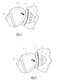
- the figure 4 illustrates another implantation configuration according to which the glenoid component 1 is placed without taking into account the resultant of forces F: in this case, unlike the figure 3 it is found that the position of the component 1 does not satisfactorily balance the action of the resultant F on the mobility of the prosthetic shoulder, so that as soon as the patient returns to his daily activities and at each once it repeats the gestures that led to the appearance of the worn area G 1 of its glenoid surface G, the shoulder prosthesis will be solicited according to an unbalanced configuration between its components 1 and 2, from where, at the long, a significant risk of instability of the prosthesis.
- a preferential position of implantation of the glenoid component 1 on the scapula S has been determined, which preferential position takes into account the action of the resultant of forces F on the prosthesis joint between the shoulder blade and the humerus H of the patient.
- the different steps of this method can be implemented outside a surgical procedure, properly speaking, aimed at implanting the glenoid component 1, in the sense that these steps are implemented without having to actually access the the scapula S and the humerus H of the patient, in particular via incisions of the soft parts surrounding these bones.
- this set 12 comprises a computer 14 associated with a unit for transmitting and receiving infrared radiation, this unit comprising a sensor 16 connected to the computer and an infrared power source 18 covering the operating field in which is represented the scapula S of the patient.
- the assembly 12 comprises a group of markers 20 which passively return the infrared radiation towards the sensor 16.
- This group of markers 20 forms a three-dimensional marking system allowing the sensors 16 to follow in space the position of the scapula.
- the use of such markers is well known in the field of computer-assisted orthopedics, for example in the document EP-A-1,249,213 , so these markers will not be described here further.
- the computer 14 is also associated with a video screen 22 able to display information useful to the surgeon, in particular the information relating to the location of the scapula S and other data described below, preferably in the form of graphic representations.
- the assembly 12 also comprises control means 24, for example in the form of a pedal actuable by the foot of the surgeon.
- the computer 14 establishes an unequivocal link between the spatial registration using the marker group 20 and the registration system 10. used for the implementation of the method for determining this preferred implantation position.
- the surgeon uses, for example, a probe 26 which is identified by the sensor 16, with a prior calibration: after incision of the soft parts of the patient's shoulder, the surgeon brings this probe 26 at least in the remarkable places of the scapula S used to define the tracking system 10 and, by actuation of the control pedal 24, the surgeon has the computer 14 record the position of the probe 26. Then, from these data, the computer 14 is able to calculate the mathematical link between the registration system 10 and the spatial registration of the sensors 16.
- the surgeon then sets up the glenoid component 1 on the scapula S according to the preferred implantation position.
- the corresponding gestures of the surgeon are advantageously guided by navigation means controlled by the computer 14. This aspect of surgical guidance is well known in the orthopedic field and will therefore not be described here further.
- mapping data may thus complete or even constitute in full the mapping data used for the implementation of the method for determining the preferred implantation position of the glenoid component 1: in other words in this case, the implementation of this determination method is performed peroperatively, unlike the case mentioned above where the implementation of this method has been described as being pre-operation.
- mapping data relating to the scapula S are thus obtained intraoperatively by means of the probe 26 brought to the glenoid surface G.
Landscapes
- Health & Medical Sciences (AREA)
- Life Sciences & Earth Sciences (AREA)
- Engineering & Computer Science (AREA)
- General Health & Medical Sciences (AREA)
- Oral & Maxillofacial Surgery (AREA)
- Public Health (AREA)
- Animal Behavior & Ethology (AREA)
- Veterinary Medicine (AREA)
- Biomedical Technology (AREA)
- Heart & Thoracic Surgery (AREA)
- Physics & Mathematics (AREA)
- Orthopedic Medicine & Surgery (AREA)
- Surgery (AREA)
- Transplantation (AREA)
- Biophysics (AREA)
- Medical Informatics (AREA)
- Molecular Biology (AREA)
- Pathology (AREA)
- Cardiology (AREA)
- Vascular Medicine (AREA)
- Dentistry (AREA)
- General Physics & Mathematics (AREA)
- Theoretical Computer Science (AREA)
- Nuclear Medicine, Radiotherapy & Molecular Imaging (AREA)
- Rheumatology (AREA)
- Mathematical Physics (AREA)
- Mathematical Optimization (AREA)
- Computational Mathematics (AREA)
- Mathematical Analysis (AREA)
- Pure & Applied Mathematics (AREA)
- Data Mining & Analysis (AREA)
- Physical Education & Sports Medicine (AREA)
- Manufacturing & Machinery (AREA)
- Geometry (AREA)
- General Engineering & Computer Science (AREA)
- Algebra (AREA)
- Software Systems (AREA)
- Databases & Information Systems (AREA)
- Computing Systems (AREA)
- Human Computer Interaction (AREA)
Abstract
Description
- La présente invention concerne un dispositif et un procédé de détermination d'une configuration d'implantation chez un patient d'un composant glénoïdien d'une prothèse d'épaule. Elle concerne également un dispositif et un procédé de détermination d'une configuration d'application d'un outil de resurfaçage glénoïdien.
- Le remplacement de la surface articulaire glénoïdienne de l'omoplate d'un être humain par un composant glénoïdien d'une prothèse d'épaule est une opération chirurgicale délicate, notamment en raison de l'environnement musculaire de l'épaule. On constate que, selon la position d'implantation d'un tel composant glénoïdien, des risques de descellement du composant existent en raison des efforts appliqués à ce composant lors des mouvements ultérieurs de l'épaule prothésée.
- En particulier, chez certains patients, on a constaté que, même si l'implantation sur leur omoplate d'un tel composant glénoïdien était parfaitement centrée sur la tête articulaire de l'humérus correspondant à l'issue de l'intervention chirurgicale d'implantation, la reprise de leurs activités conduisait, plus ou moins rapidement, à une instabilité de la prothèse. Une explication tiendrait au fait que l'implantation du composant glénoïdien n'a pas été réalisée en tenant compte de forces d'origine musculaire générées régulièrement par le patient dans le cadre de ses activités de tous les jours.
- Pour contourner cette problématique,
US-A-2009/0226068 propose de fabriquer un composant glénoïdien « sur mesure » dont la surface articulaire est conformée, lors de sa conception, en tenant compte de l'usure constatée sur la glène à prothéser d'un patient. Une telle approche s'avère cependant onéreuse puisqu'elle conduit à personnaliser le composant glénoïdien pour chaque patient à traiter. De plus,US-A-2009/0226068 prévoit d'implanter ces composants glénoïdien « sur mesure » de manière traditionnelle, si bien qu'il subsiste un risque que l'implantation finalement réalisée ne soit pas pleinement satisfaisante, pour les raisons développées plus haut. - On retrouve des considérations similaires pour les opérations de resurfaçage glénoïdien de l'omoplate.
- Le but de la présente invention est d'optimiser soit la configuration d'implantation d'un composant glénoïdien, soit la configuration d'un outil de resurfaçage glénoïdien, en tenant davantage compte de l'action, sur l'articulation de l'épaule prothésée ou resurfacée d'un patient, des forces d'origine musculaire liées à une activité articulaire régulière de ce patient.
- A cet effet, l'invention a pour objet un dispositif de détermination d'une configuration dans laquelle soit un composant glénoïdien d'une prothèse d'épaule est à implanter sur l'omoplate d'un patient, soit un outil de resurfaçage glénoïdien est à appliquer sur l'omoplate d'un patient, ce dispositif étant tel que défini à la revendication 1.
- L'invention a également pour objet un procédé de détermination d'une configuration dans laquelle soit un composant glénoïdien d'une prothèse d'épaule est à implanter sur l'omoplate d'un patient, soit un outil de resurfaçage glénoïdien est à appliquer sur l'omoplate d'un patient, ce procédé étant tel que défini à la revendication 10.
- Une des idées à la base de l'invention est de chercher à positionner un composant glénoïdien pré-existant non pas lorsque l'articulation de l'épaule du patient à opérer est considérée au repos, mais lorsque cette articulation est considérée soumise à des forces d'origine musculaire liées à une activité régulière de ce patient, typiquement une activité articulaire que ce patient répète plusieurs fois par jour. Pour « remonter » à une caractérisation vectorielle d'une résultante de ces forces, l'invention exploite des données relatives à l'usure constatée de la surface glénoïdienne du patient. Et grâce aux caractéristiques vectorielles de la résultante forces précitée, on peut déterminer une configuration d'implantation du composant prothétique glénoïdien, en considérant l'influence positionnelle de cette résultante de forces sur la coopération articulaire entre l'omoplate et l'humérus du patient. De cette façon, après implantation chirurgicale du composant glénoïdien conformément à la position d'implantation déterminée grâce à l'invention, les efforts liés à l'activité régulière du patient seront appliqués de manière équilibrée sur l'articulation entre l'omoplate prothésée et l'humérus, si bien que le patient pourra reprendre cette activité régulière en limitant le risque que cette dernière conduise rapidement à une instabilité de la prothèse implantée.
- L'invention peut être appliquée à un composant glénoïdien d'une prothèse d'épaule totale, la tête de l'humérus du patient étant alors à prothéser par un composant huméral de la prothèse d'épaule. L'invention peut également être appliquée à un composant prothétique glénoïdien destiné à s'articuler directement sur la tête articulaire naturelle de l'humérus du patient. Par ailleurs, l'invention s'applique aussi bien aux composants glénoïdiens dont la face articulaire est concave, qu'aux composants à face articulaire convexe.
- De plus, comme spécifié plus haut dans la définition de l'invention, cette dernière peut être mise en oeuvre dans le cadre du resurfaçage glénoïdien de l'omoplate d'un patient, typiquement par fraisage. L'invention s'applique alors au positionnement de l'outil de fraisage sur l'omoplate.
- On remarquera que toutes les étapes du procédé de détermination défini plus haut peuvent être mises en oeuvre de manière pré-opératoire, notamment à l'aide de moyens de calcul et de simulation ad hoc. Le résultat de ce procédé est, quant à lui, exploitable ultérieurement, lors d'une intervention chirurgicale subséquente visant effectivement à implanter un composant glénoïdien ou à appliquer un outil de resurfaçage glénoïdien.
- D'autres caractéristiques avantageuses du dispositif de détermination conforme à l'invention, prises isolément ou selon toutes les combinaisons techniquement possibles, sont spécifiées aux revendications dépendantes 2 à 9.
- Par ailleurs, le procédé de détermination conforme à l'invention présente avantageusement des aspects additionnels qui correspondent respectivement à la mise en oeuvre des caractéristiques additionnelles avantageuses listées ci-dessus pour le dispositif de détermination.
- En lien avec l'invention, il est proposé une méthode chirurgicale d'implantation chez un patient d'un composant glénoïdien d'une prothèse d'épaule, dans laquelle :
- on détermine une position préférentielle d'implantation du composant glénoïdien conformément au procédé de détermination tel que défini plus haut,
- on repère dans l'espace l'omoplate du patient, avec un lien univoque avec le système de repérage défini dans le procédé de détermination, et
- on met en place le composant glénoïdien sur l'omoplate du patient selon la position d'implantation préférentielle.
- Avantageusement, au moins une partie des données de cartographie sont acquises par palpation de l'omoplate du patient.
- Egalement en lien avec l'invention, il est proposé une méthode chirurgicale de resurfaçage glénoïdien de l'omoplate d'un patient, dans laquelle :
- on détermine un positionnement préférentiel d'application d'un outil de resurfaçage conformément au procédé de détermination tel que défini plus haut,
- on repère dans l'espace l'omoplate du patient, avec un lien univoque avec le système de repérage défini dans le procédé de détermination, et
- on rectifie la surface glénoïdienne de l'omoplate en appliquant sur cette dernière l'outil de resurfaçage selon le positionnement d'application préférentiel.
- Avantageusement, au moins une partie des données de cartographie sont acquises par palpation de l'omoplate du patient.
- L'invention sera mieux comprise à la lecture de la description qui va suivre, donnée uniquement à titre d'exemple et faite en se référant aux dessins sur lesquels :
- la
figure 1 est une vue schématique en perspective et en éclaté de l'épaule d'un patient, associée à des composants prothétiques d'une prothèse d'épaule ; - la
figure 2 est une coupe schématique de l'épaule, non prothésée, de lafigure 1 ; - les
figures 3 et 4 sont des vues analogues à lafigure 2 , montrant en élévation deux configurations différentes d'implantation de la prothèse d'épaule de lafigure 1 ; et - la
figure 5 est une vue schématique d'un système d'implantation chez le patient du composant glénoïdien de la prothèse d'épaule. - Sur les
figures 1 et 2 est montré, en partie, une épaule d'un patient, comprenant une omoplate S et un humérus H. L'omoplate S délimite, sur son côté latéral tourné vers l'humérus H, une surface glénoïdienne G. A l'état naturel de l'épaule, la tête T de l'humérus H s'appuie de manière articulée contre la surface glénoïdienne G. De manière non représentée sur les figures, la coopération articulaire entre l'omoplate S et l'humérus H est commandée par des muscles s'étendant entre l'omoplate et l'humérus, en particulier le muscle deltoïde et les muscles de la coiffe des rotateurs. Par la suite, on utilise l'expression « environnement musculaire » pour désigner les muscles précités. - Sur les
figures 1 ,3 et 4 est représentée, de manière très schématique, une prothèse d'épaule connue en soi, comprenant un composant glénoïdien 1 et un composant huméral 2. Dans l'exemple non limitatif considéré ici, ces composants glénoïdien 1 et huméral 2 présentent des formes globales respectives de portion de coupelle, en délimitant des faces articulaires respectives 1A et 2A géométriquement complémentaires l'une de l'autre de manière que ces composants s'articulent l'un sur l'autre. - On va décrire ci-après comment déterminer une configuration d'implantation du composant glénoïdien 1 sur l'omoplate S, en tenant compte de l'environnement musculaire de l'épaule.
- Pour ce faire, on considère qu'on dispose initialement de données relatives à la géométrie anatomique de l'omoplate S. Ces données sont prévues pour dresser une cartographie tri-dimensionnelle de la surface glénoïdienne G de cette omoplate, après avoir défini un système 10 de repérage dans l'espace de l'omoplate S. Ce système de repérage spatial 10 est par exemple établi à l'aide de points de repère naturels remarquables de cette omoplate.
- En pratique, les données de cartographie relatives à la géométrie naturelle de la surface glénoïdienne G sont avantageusement extraites depuis des images pré-opératoires de l'omoplate S, en particulier des images de scanner. La
figure 2 correspond, en quelque sorte, à une telle image pré-opératoire. - A partir des données de cartographie précitées, on caractérise l'usure de la surface glénoïdienne G. Ainsi, dans l'exemple considéré sur les
figures 1 et 2 , la surface glénoïdienne G présente, dans sa partie inférieure et suivant toute sa dimension antéro-postérieure, une zone usée G1, vue en coupe sur lafigure 2 , étant remarqué que les usures glénoïdiennes sont plutôt constatées le plus souvent dans la partie supérieure de la surface glénoïdienne. - En pratique, la zone usée G1 est caractérisée par ses caractéristiques géométriques, appréciées par rapport au reste de la surface glénoïdienne G. Ainsi, à titre non limitatif, la zone usée G1 est caractérisée par les dimensions de son contour périphérique dans les trois directions du système de repérage 10, par ses gradients de profondeur dans le système de repérage 10, etc. En fait, de manière plus générale, ces caractéristiques géométriques d'usure sont choisies pour permettre, comme expliqué en détail plus loin, de « remonter » aux causes mécaniques à l'origine de l'usure de la surface glénoïdienne G.
- Pour déterminer les caractéristiques géométriques d'usure de la surface glénoïdienne G, plusieurs possibilités sont envisageables. L'une d'elles consistent à comparer les données de cartographie relatives à la surface glénoïdienne G, obtenues précédemment, à des données relatives à l'anatomie d'une surface glénoïdienne de référence, de telles données de comparaison étant fournies par une base de données pré-existante.
- Une autre possibilité consiste, sur la base des données de cartographie relatives à une partie seulement de la surface glénoïdienne G, considérée comme non usée, à modéliser une surface glénoïdienne théorique, par le biais d'algorithmes de reconnaissance de formes et de données génétiques et morphométriques préétablies, puis de comparer les données de cartographie restantes, en particulier celles relatives à la zone usée G1, à cette surface glénoïdienne théorique.
- L'intérêt de disposer des caractéristiques géométriques d'usure de la surface glénoïdienne G est, lors d'une étape subséquente, d'utiliser ces caractéristiques pour estimer les forces responsables de la formation de la zone usée G1. En effet, l'apparition et l'évolution de la zone usée G1 au sein de la surface glénoïdienne G sont la conséquence de l'action régulière et répétitive d'une certaine configuration de l'environnement musculaire de l'épaule du patient : en raison d'une activité articulaire régulière du patient, c'est-à-dire de gestes qu'il répète de manière fréquente dans le cadre de sa vie quotidienne, l'environnement musculaire de l'épaule applique à l'omoplate S et à l'humérus H des contraintes répétées qui, à la longue, entraînent l'apparition et le développement de l'usure de la surface glénoïdienne G au niveau de la zone G1. Cette action de l'environnement musculaire peut être représentée par une résultante de forces, notée F sur la
figure 2 , dont les caractéristiques vectorielles sont déterminées à partir des caractéristiques géométriques d'usure de la surface glénoïdienne G. - En pratique, pour « remonter » aux caractéristiques vectorielles de la résultante de forces F à partir des caractéristiques géométriques d'usure de la surface glénoïdienne G, on utilise avantageusement un modèle musculo-squelettique d'épaule pré-existant. Un tel modèle bio-mécanique permet de simuler les mouvements articulaires de l'épaule, en quantifiant les forces dans l'articulation entre l'omoplate et l'humérus de l'épaule, ainsi que dans l'environnement musculaire de l'épaule. De cette façon, un tel modèle musculo-squelettique d'épaule peut être utilisé pour construire une base de données d'usure : pour ce faire, on simule plusieurs usures glénoïdiennes au sein de ce modèle, respectivement sous l'action de différentes forces prédéterminées correspondantes. Par comparaison des caractéristiques géométriques d'usure de la surface glénoïdienne G à la base de données d'usure ainsi pré-établie, on déduit, le cas échéant par approximation, les caractéristiques vectorielles de la résultante de forces F.
- Enfin, en utilisant les caractéristiques vectorielles de la résultante de forces F, on détermine une position optimale d'implantation du composant glénoïdien 1 sur l'omoplate S de telle sorte que, en service ultérieur, le composant glénoïdien s'oppose à la résultante de forces F. Autrement dit, on tient ainsi compte de l'action de cette résultante de forces F sur la coopération articulaire à venir entre le composant glénoïdien 1 et le composant huméral 2, selon la configuration relative d'implantation de ces composants au sein de l'épaule du patient. Pour ce faire, selon une mise en oeuvre préférée, on utilise de nouveau le modèle musculo-squelettique d'épaule évoqué plus haut, pour simuler l'articulation entre l'omoplate S et l'humérus H, soumise à des efforts musculaires correspondant à la résultante F et calculer alors, dans le système de repérage 10, les caractéristiques géométriques d'une position d'implantation du composant glénoïdien 1 de manière que la mobilité relative entre ce dernier et le composant huméral 2 soit équilibrée sous l'effet de la résultante des forces F. En pratique, cet équilibrage est avantageusement déterminé de sorte que, au cours des mouvements de l'épaule prothésée produisant des efforts de résultante F, la zone de contact articulaire entre l'omoplate S et l'humérus H est sensiblement centrée par rapport au contour périphérique du composant glénoïdien, et non décalée vers une portion périphérique de ce dernier.
- Ainsi, les caractéristiques géométriques précitées, relatives à la position d'implantation du composant glénoïdien. 1, permettent de quantifier tous les paramètres de positionnement vis-à-vis de l'omoplate S dans le système de repérage 10, à savoir sa hauteur dans les trois directions de ce système de repérage, ainsi que son inclinaison selon ces trois directions.
- La position d'implantation du composant glénoïdien 1 ainsi déterminée est montrée sur la
figure 3 qui illustre l'équilibrage entre composant glénoïdien 1 et le composant huméral 2 alors que l'omoplate S et l'humérus H de l'épaule du patient à opérer subissent l'effet de la résultante de forces F. A l'inverse, lafigure 4 illustre une autre configuration d'implantation selon laquelle le composant glénoïdien 1 est placé sans tenir compte de la résultante de forces F : dans ce cas, contrairement à lafigure 3 , on constate que la position du composant 1 n'équilibre pas de façon satisfaisante l'action de la résultante F sur la mobilité de l'épaule prothésée, si bien que, dès que le patient reprendra ses activités de tous les jours et à chaque fois qu'il répètera les gestes ayant conduit à l'apparition de la zone usée G1 de sa surface glénoïdienne G, la prothèse d'épaule sera sollicitée selon une configuration non équilibrée entre ses composants 1 et 2, d'où, à la longue, un risque significatif d'instabilité de la prothèse. - Ainsi, à l'issue du procédé qui vient d'être décrit, on a déterminé une position préférentielle d'implantation du composant glénoïdien 1 sur l'omoplate S, position préférentielle qui tient compte de l'action de la résultante de forces F sur l'articulation à prothéser entre l'omoplate et l'humérus H du patient. On souligne ici que les différentes étapes de ce procédé peuvent être mises en oeuvre en dehors d'une intervention chirurgicale, proprement dite, visant à implanter le composant glénoïdien 1, dans le sens où ces étapes sont mises en oeuvre sans avoir à accéder réellement à l'omoplate S et à l'humérus H du patient, notamment via des incisions des parties molles entourant ces os.
- Par ailleurs, en pratique, la mise en oeuvre des étapes décrites jusqu'ici sont avantageusement assistées par des moyens informatiques, en particulier pour réaliser les calculs de positionnement relatif et les calculs de simulation évoqués jusqu'ici.
- Ultérieurement, un chirurgien va utiliser les données, obtenues par le procédé décrit jusqu'ici, relatives à la position préférentielle d'implantation du composant glénoïdien 1. A cette fin, le chirurgien utilise notamment un ensemble chirurgical 12 montré sur la
figure 5 : cet ensemble 12 comprend un ordinateur 14 associé à une unité d'émission et de réception d'un rayonnement infrarouge, cette unité comportant un capteur 16 relié à l'ordinateur et une source d'alimentation infrarouge 18 couvrant le champ opératoire dans lequel est représentée l'omoplate S du patient. Pour permettre à l'ordinateur 14 de repérer dans l'espace l'omoplate S, l'ensemble 12 comporte un groupe de marqueurs 20 qui renvoient, de façon passive, le rayonnement infrarouge en direction du capteur 16. Ce groupe de marqueurs 20 forme un système de marquage tri-dimensionnel permettant aux capteurs 16 de suivre dans l'espace la position de l'omoplate. L'utilisation de tels marqueurs est bien connue dans le domaine de l'orthopédie assistée par ordinateur, par exemple dans le documentEP-A-1 249 213 , de sorte que ces marqueurs ne seront pas décrits ici plus avant. - Avantageusement, l'ordinateur 14 est également associé à un écran vidéo 22 à même d'afficher des informations utiles au chirurgien, notamment les informations relatives au repérage de l'omoplate S et d'autres données décrites plus loin, de préférence sous forme de représentations graphiques. L'ensemble 12 comprend également des moyens de commande 24, par exemple sous forme d'une pédale actionnable par le pied du chirurgien.
- En vue d'implanter le composant glénoïdien 1 dans la position d'implantation préférentielle précitée, on établit, grâce à l'ordinateur 14, un lien univoque entre le repérage spatial à l'aide du groupe de marqueurs 20 et le système de repérage 10 utilisé pour la mise en oeuvre du procédé de détermination de cette position d'implantation préférentielle. Pour ce faire, le chirurgien utilise, à titre d'exemple, un palpeur 26 qui est repéré par le capteur 16, moyennant un étalonnage préalable : après incision des parties molles de l'épaule du patient, le chirurgien amène ce palpeur 26 au moins sur les lieux remarquables de l'omoplate S ayant servi à définir le système de repérage 10 et, par actionnement de la pédale de commande 24, le chirurgien fait enregistrer à l'ordinateur 14 la position du palpeur 26. Puis, à partir de ces données, l'ordinateur 14 est à même de calculer le lien mathématique entre le système de repérage 10 et le repérage spatial des capteurs 16.
- Le chirurgien met ensuite en place le composant glénoïdien 1 sur l'omoplate S selon la position d'implantation préférentielle. En pratique, les gestes correspondants du chirurgien sont avantageusement guidés par des moyens de navigation pilotés par l'ordinateur 14. Cet aspect de guidage chirurgical est bien connu dans le domaine orthopédique et ne sera donc pas décrit ici plus avant.
- A titre optionnel, après que le chirurgien a incisé les parties molles de l'épaule du patient mais avant qu'il commence à mettre en place le composant glénoïdien 1, le chirurgien peut mettre à profit son accès à l'omoplate S pour recueillir des données de cartographie relatives à la surface glénoïdienne G. Ces données de cartographie pourront ainsi compléter, voire constituer en totalité les données de cartographie utilisées pour la mise en oeuvre du procédé de détermination de la position d'implantation préférentielle du composant glénoïdien 1 : autrement dit, dans ce cas, la mise en oeuvre de ce procédé de détermination est réalisée de manière per-opératoire, contrairement au cas de figure évoqué plus haut où la mise en oeuvre de ce procédé a été décrite comme étant de manière pré-opératoire.
- A titre d'exemple, les données de cartographie relatives à l'omoplate S sont ainsi obtenues en per-opératoire à l'aide du palpeur 26 amené sur la surface glénoïdienne G.
- Divers aménagements et variantes au procédé de détermination et au dispositif permettant sa mise en oeuvre, ainsi qu'à la méthode chirurgicale d'implantation et à l'ensemble permettant la mise en oeuvre de cette méthode, sont par ailleurs envisageables. A titre d'exemples :
- les moyens de repérage de l'omoplate S et/ou du palpeur 26 ne sont pas limités à des marqueurs réfléchissant l'infrarouge ; les marqueurs sensibles aux ultrasons ou à des champs électromagnétiques sont notamment utilisables ;
- plutôt que la position d'implantation du composant huméral 2 sur l'humérus H soit prédéterminée, cette implantation peut être réglée concomitamment à la détermination d'une configuration d'implantation du composant glénoïdien 1 ;
- comme évoqué dans la partie introductive de ce document, l'invention peut être mise en oeuvre pour déterminer une configuration d'implantation préférentielle d'un composant glénoïdien s'articulant directement sur la tête naturelle de l'humérus H, sans nécessiter l'implantation d'un composant huméral tel que le composant 2 ; et/ou
- l'invention peut également être mise en oeuvre dans le cadre du resurfaçage glénoïdien de l'omoplate S, avec ou sans mise en place subséquente d'un implant de resurfaçage ; dans ce cas, plutôt que de déterminer une position d'implantation du composant glénoïdien 1, comme décrit plus haut, l'invention est appliquée pour déterminer un positionnement d'application d'un outil de resurfaçage sur l'omoplate, afin de rectifier sa surface glénoïdienne G pour que cette dernière puisse ensuite s'articuler au mieux avec la tête de l'humérus H, c'est-à-dire en tenant compte de l'action de la résultante de forces F sur cette articulation ; les considérations détaillées jusqu'ici quant à la détermination d'une configuration d'implantation du composant glénoïdien 1 s'appliquent mutatis mutandis à la détermination d'une configuration de positionnement de l'outil de resurfaçage sur l'omoplate.
Claims (10)
- Dispositif de détermination d'une configuration dans laquelle soit un composant glénoïdien (1) d'une prothèse d'épaule est à implanter sur l'omoplate (S) d'un patient, soit un outil sur resurfaçage glénoïdien est à appliquer sur l'omoplate d'un patient, ce dispositif comportant :- des moyens de cartographie pour disposer de données de cartographie relatives à la surface glénoïdienne (G) de l'omoplate (S), ces données de cartographie étant définies dans un système de repérage spatial (10) de l'omoplate,- des premiers moyens de détermination pour, à partir de données de cartographie fournies par les moyens de cartographie, déterminer des caractéristiques géométriques d'usure de la surface glénoïdienne (G),- des deuxièmes moyens de détermination pour, à partir de caractéristiques géométriques d'usure fournies par les premiers moyens de détermination, déterminer les caractéristiques vectorielles d'une résultante (F) de forces responsables de l'usure de la surface glénoïdienne (G), et- des troisièmes moyens de détermination pour, à partir des caractéristiques vectorielles d'une résultante de forces (F) fournies par les deuxièmes moyens de détermination, déterminer soit une position d'implantation du composant glénoïdien (1) sur l'omoplate (S), soit un positionnement d'application de l'outil de resurfaçage sur l'omoplate, en tenant compte de l'action de ladite résultante de forces sur la coopération articulaire entre l'omoplate, respectivement prothésée ou resurfacée, et l'humérus (H) du patient.
- Dispositif suivant la revendication 1, caractérisé en ce que les moyens de cartographie comprennent des images pré-opératoires, telles que des images de scanner.
- Dispositif suivant l'une des revendications 1 ou 2, caractérisé en ce que les premiers moyens de détermination sont adaptés pour comparer les données de cartographie à des données relatives à une anatomie de référence pour une surface glénoïdienne, fournies par une base de données pré-existante.
- Dispositif suivant l'une des revendications 1 ou 2, caractérisé en ce qu'il comporte en outre des moyens pour modéliser une surface glénoïdienne théorique à partir d'une partie seulement des données de cartographie, cette partie des données de cartographie correspondant sélectivement à une partie seulement de la surface glénoïdienne (G) de l'omoplate (S), et en ce que les premiers moyens de détermination sont adaptés pour comparer le reste des données de cartographie à la surface glénoïdienne théorique fournie par les moyens de modélisation.
- Dispositif suivant l'une quelconque des revendications précédentes, caractérisé en ce que les deuxièmes moyens de détermination sont adaptés pour comparer les caractéristiques géométriques d'usure à des données d'usure pré-établies à l'aide d'un modèle musculo-squelettique d'épaule pré-existant.
- Dispositif suivant la revendication 5, caractérisé en ce que lesdites données d'usure pré-établies sont obtenues en simulant des usures glénoïdiennes du modèle musculo-squelettique d'épaule sous les actions respectives de forces prédéterminées correspondantes.
- Dispositif suivant l'une quelconque des revendications précédentes, caractérisé en ce que les troisièmes moyens de détermination sont adaptés pour déterminer soit la position d'implantation du composant glénoïdien (1), soit le positionnement d'application de l'outil de resurfaçage de telle sorte que la coopération articulaire entre l'omoplate (S), respectivement prothésée ou resurfacée, et l'humérus (H) soit équilibrée sous l'effet d'une force conforme aux caractéristiques vectorielles de ladite résultante de forces (F).
- Dispositif suivant la revendication 7, caractérisé en ce que les troisièmes moyens de détermination incluent des moyens de calcul pour, à partir d'un modèle musculo-squelettique d'épaule pré-existant, simuler la coopération articulaire entre l'omoplate (S) et l'humérus (H), soumise à une force conforme aux caractéristiques vectorielles de ladite résultante de forces (F).
- Dispositif suivant l'une des revendications 7 ou 8, caractérisé en ce que les troisième moyens de détermination sont adaptés pour calculer les caractéristiques géométriques, dans le système de repérage spatial (10), soit de la position d'implantation du composant glénoïdien (1), soit du positionnement d'application de l'outil de resurfaçage de telle sorte que, lorsque l'épaule du patient se trouve sollicitée de façon à appliquer à l'articulation entre l'omoplate (S) et l'humérus (H) une force conforme aux caractéristiques vectorielles de ladite résultante de forces (F), la zone de contact articulaire entre l'omoplate, respectivement prothésée ou resurfacée, et l'humérus est sensiblement centrée par rapport au contour périphérique du composant glénoïdien ou du resurfaçage.
- Procédé de détermination d'une configuration dans laquelle soit un composant glénoïdien (1) d'une prothèse d'épaule est à implanter sur l'omoplate (S) d'un patient, soit un outil de resurfaçage glénoïdien est à appliquer sur l'omoplate d'un patient, procédé dans lequel :- on définit un système de repérage spatial (10) de l'omoplate (S),- on dispose de données de cartographie relatives à la surface glénoïdienne (G) de cette omoplate (S), ces données de cartographie étant définies dans le système de repérage (10),- à partir de ces données de cartographie, on détermine des caractéristiques géométriques d'usure de la surface glénoïdienne (G),- à partir de ces caractéristiques géométriques d'usure, on détermine les caractéristiques vectorielles d'une résultante (F) de forces responsables de l'usure de la surface glénoïdienne (G), et- à partir de ces caractéristiques vectorielles de la résultante de forces (F), on détermine soit une position d'implantation du composant glénoïdien (1) sur l'omoplate (S), soit un positionnement d'application de l'outil de resurfaçage sur l'omoplate, en tenant compte de l'action de cette résultante de forces sur la coopération articulaire entre l'omoplate, respectivement prothésée ou resurfacée, et l'humérus (H) du patient.
Applications Claiming Priority (2)
| Application Number | Priority Date | Filing Date | Title |
|---|---|---|---|
| US26402709P | 2009-11-24 | 2009-11-24 | |
| FR1050541A FR2955481B1 (fr) | 2010-01-27 | 2010-01-27 | Dispositif et procede de caracterisation glenoidienne d'une omoplate a protheser ou a resurfacer |
Publications (2)
| Publication Number | Publication Date |
|---|---|
| EP2324801A1 true EP2324801A1 (fr) | 2011-05-25 |
| EP2324801B1 EP2324801B1 (fr) | 2021-05-12 |
Family
ID=42346720
Family Applications (1)
| Application Number | Title | Priority Date | Filing Date |
|---|---|---|---|
| EP10191949.6A Active EP2324801B1 (fr) | 2009-11-24 | 2010-11-19 | Dispositif et procédé de détermination d'une configuration d'implantation d'un composant prothétique glénoïdien ou d'une configuration d'application d'un outil de resurfaçage glénoïdien |
Country Status (3)
| Country | Link |
|---|---|
| US (6) | US9211199B2 (fr) |
| EP (1) | EP2324801B1 (fr) |
| FR (1) | FR2955481B1 (fr) |
Cited By (9)
| Publication number | Priority date | Publication date | Assignee | Title |
|---|---|---|---|---|
| WO2015068035A1 (fr) * | 2013-11-08 | 2015-05-14 | Imascap | Méthodes, systèmes et dispositifs pour implants glénoïdiens adaptatifs à planification pré-opératoire |
| WO2015071757A1 (fr) | 2013-11-13 | 2015-05-21 | Tornier Sas | Instrument spécifique à l'épaule d'un patient |
| US10716676B2 (en) | 2008-06-20 | 2020-07-21 | Tornier Sas | Method for modeling a glenoid surface of a scapula, apparatus for implanting a glenoid component of a shoulder prosthesis, and method for producing such a component |
| US10959742B2 (en) | 2017-07-11 | 2021-03-30 | Tornier, Inc. | Patient specific humeral cutting guides |
| US11065016B2 (en) | 2015-12-16 | 2021-07-20 | Howmedica Osteonics Corp. | Patient specific instruments and methods for joint prosthesis |
| US11166733B2 (en) | 2017-07-11 | 2021-11-09 | Howmedica Osteonics Corp. | Guides and instruments for improving accuracy of glenoid implant placement |
| US12070272B2 (en) | 2013-10-10 | 2024-08-27 | Stryker European Operations Limited | Methods, systems and devices for pre-operatively planned shoulder surgery guides and implants |
| US12193939B2 (en) | 2017-12-29 | 2025-01-14 | Howmedica Osteonics Corp. | Patient specific humeral implant components |
| US12521246B2 (en) | 2016-03-25 | 2026-01-13 | Tornier Sas | Bone graft shaper and patient specific bone graft |
Families Citing this family (9)
| Publication number | Priority date | Publication date | Assignee | Title |
|---|---|---|---|---|
| FR2955481B1 (fr) * | 2010-01-27 | 2013-06-14 | Tornier Sa | Dispositif et procede de caracterisation glenoidienne d'une omoplate a protheser ou a resurfacer |
| US10575968B2 (en) | 2014-05-16 | 2020-03-03 | Howmedica Osteonics Corp. | Guides for fracture system |
| US9681960B2 (en) | 2014-05-16 | 2017-06-20 | Howmedica Osteonics Corp. | Guides for fracture system |
| EP3810017A1 (fr) | 2018-06-19 | 2021-04-28 | Tornier, Inc. | Listes de contrôle virtuelles pour chirurgie orthopédique |
| US12465374B2 (en) | 2019-12-18 | 2025-11-11 | Howmedica Osteonics Corp. | Surgical guidance for surgical tools |
| US11890058B2 (en) | 2021-01-21 | 2024-02-06 | Arthrex, Inc. | Orthopaedic planning systems and methods of repair |
| US12178515B2 (en) | 2021-04-26 | 2024-12-31 | Arthrex, Inc. | Systems and methods for density calibration |
| US12082896B2 (en) * | 2021-08-04 | 2024-09-10 | Pixee Medical | Surgical navigation system on wearable computer combining augmented reality and robotics |
| US11759216B2 (en) | 2021-09-22 | 2023-09-19 | Arthrex, Inc. | Orthopaedic fusion planning systems and methods of repair |
Citations (7)
| Publication number | Priority date | Publication date | Assignee | Title |
|---|---|---|---|---|
| US5610966A (en) * | 1995-02-15 | 1997-03-11 | Argonne National Laboratories/University Of Chicago Development Corp. | Method and device for linear wear analysis |
| EP1249213A2 (fr) | 1997-03-11 | 2002-10-16 | Aesculap AG & Co. KG | Méthode et dispositif pour la détermination préopératoire de données de positionement de parties d'endoprothèses |
| US20050197814A1 (en) * | 2004-03-05 | 2005-09-08 | Aram Luke J. | System and method for designing a physiometric implant system |
| US20070089518A1 (en) * | 2005-10-26 | 2007-04-26 | Ericson Milton N | Method and apparatus for orthopedic implant assessment |
| US20080243127A1 (en) * | 2001-05-25 | 2008-10-02 | Conformis, Inc. | Surgical Tools for Arthroplasty |
| US20090226068A1 (en) | 2008-03-05 | 2009-09-10 | Conformis, Inc. | Implants for Altering Wear Patterns of Articular Surfaces |
| EP2135576A1 (fr) * | 2008-06-20 | 2009-12-23 | Tornier | Procédé de modélisation d'une surface glénoïdienne d'une omoplate, dispositif d'implantation d'un composant glénoïdien d'une prothèse d'épaule, et procédé de fabrication d'un tel composant |
Family Cites Families (72)
| Publication number | Priority date | Publication date | Assignee | Title |
|---|---|---|---|---|
| FR2579454A1 (fr) | 1985-03-28 | 1986-10-03 | Rambert Andre | Prothese gleno-humerale |
| ATE311149T1 (de) * | 2000-08-31 | 2005-12-15 | Plus Endoprothetik Ag | Anordnung zur ermittlung einer belastungsachse einer extremität |
| WO2002061688A2 (fr) | 2001-01-29 | 2002-08-08 | The Acrobot Company Limited | Modelisation en chirurgie |
| WO2004032806A1 (fr) | 2002-10-07 | 2004-04-22 | Conformis, Inc. | Implant articulaire par chirurgie non effractive a geometrie tridimensionnelle correspondant aux surfaces articulaires |
| FR2859099B1 (fr) | 2003-08-25 | 2006-01-06 | Tornier Sa | Composant glenoidien de prothese d'epaule et prothese totale d'epaule incorporant un tel composant |
| US6944518B2 (en) | 2003-09-18 | 2005-09-13 | Depuy Products, Inc. | Customized prosthesis and method of designing and manufacturing a customized prosthesis by utilizing computed tomography data |
| FR2865928B1 (fr) | 2004-02-10 | 2006-03-17 | Tornier Sa | Dispositif chirurgical d'implantation d'une prothese totale de hanche |
| US9681925B2 (en) | 2004-04-21 | 2017-06-20 | Siemens Medical Solutions Usa, Inc. | Method for augmented reality instrument placement using an image based navigation system |
| TW200730138A (en) | 2006-02-15 | 2007-08-16 | Univ Chung Yuan Christian | Image analysis methods for gleno-humeral joint morphology |
| DE502006008018D1 (de) | 2006-05-31 | 2010-11-18 | Brainlab Ag | Verfahren zur Auswahl eines Oberschenkelimplantats |
| US7604665B2 (en) | 2006-09-20 | 2009-10-20 | Depuy Products, Inc. | Glenoid component for shoulder arthroplasty |
| US8357165B2 (en) * | 2006-12-22 | 2013-01-22 | Depuy Products, Inc. | Reference array mounting bracket for use with a computer assisted orthopaedic surgery system |
| US8377073B2 (en) * | 2008-04-21 | 2013-02-19 | Ray Wasielewski | Method of designing orthopedic implants using in vivo data |
| US20220273450A1 (en) | 2009-02-25 | 2022-09-01 | Conformis, Inc. | Patient-Adapted and Improved Orthopedic Implants, Designs and Related Guide Tools |
| US8819591B2 (en) | 2009-10-30 | 2014-08-26 | Accuray Incorporated | Treatment planning in a virtual environment |
| FR2955481B1 (fr) | 2010-01-27 | 2013-06-14 | Tornier Sa | Dispositif et procede de caracterisation glenoidienne d'une omoplate a protheser ou a resurfacer |
| US8482859B2 (en) | 2010-02-28 | 2013-07-09 | Osterhout Group, Inc. | See-through near-eye display glasses wherein image light is transmitted to and reflected from an optically flat film |
| EP2452649A1 (fr) | 2010-11-12 | 2012-05-16 | Deutsches Krebsforschungszentrum Stiftung des Öffentlichen Rechts | Visualisation de données anatomiques à réalité améliorée |
| US9123155B2 (en) | 2011-08-09 | 2015-09-01 | Covidien Lp | Apparatus and method for using augmented reality vision system in surgical procedures |
| US10467752B2 (en) | 2013-06-11 | 2019-11-05 | Atsushi Tanji | Bone cutting support system, information processing apparatus, image processing method, and image processing program |
| US20170105802A1 (en) | 2014-03-27 | 2017-04-20 | Bresmedical Pty Limited | Computer aided surgical navigation and planning in implantology |
| GB2534359A (en) | 2015-01-15 | 2016-07-27 | Corin Ltd | System and method for patient implant alignment |
| US10013808B2 (en) | 2015-02-03 | 2018-07-03 | Globus Medical, Inc. | Surgeon head-mounted display apparatuses |
| US20160324580A1 (en) | 2015-03-23 | 2016-11-10 | Justin Esterberg | Systems and methods for assisted surgical navigation |
| WO2016154557A1 (fr) | 2015-03-26 | 2016-09-29 | Universidade De Coimbra | Procédés et systèmes pour chirurgie assistée par ordinateur au moyen d'une vidéo intra-opératoire acquise par une caméra à mouvement libre |
| US10052170B2 (en) | 2015-12-18 | 2018-08-21 | MediLux Capitol Holdings, S.A.R.L. | Mixed reality imaging system, apparatus and surgical suite |
| DE102015226669B4 (de) | 2015-12-23 | 2022-07-28 | Siemens Healthcare Gmbh | Verfahren und System zum Ausgeben einer Erweiterte-Realität-Information |
| CN111329554B (zh) | 2016-03-12 | 2021-01-05 | P·K·朗 | 用于手术的装置与方法 |
| US10194990B2 (en) | 2016-04-27 | 2019-02-05 | Arthrology Consulting, Llc | Method for augmenting a surgical field with virtual guidance content |
| US11253321B2 (en) | 2016-04-27 | 2022-02-22 | Arthrology Consulting, Llc | Methods for augmenting a surgical field with virtual guidance and tracking and adapting to deviation from a surgical plan |
| US10398514B2 (en) | 2016-08-16 | 2019-09-03 | Insight Medical Systems, Inc. | Systems and methods for sensory augmentation in medical procedures |
| ES2992065T3 (es) | 2016-08-16 | 2024-12-09 | Insight Medical Systems Inc | Sistemas de aumento sensorial en procedimientos médicos |
| US10687901B2 (en) | 2016-08-17 | 2020-06-23 | Synaptive Medical (Barbados) Inc. | Methods and systems for registration of virtual space with real space in an augmented reality system |
| US10636323B2 (en) | 2017-01-24 | 2020-04-28 | Tienovix, Llc | System and method for three-dimensional augmented reality guidance for use of medical equipment |
| US10010379B1 (en) | 2017-02-21 | 2018-07-03 | Novarad Corporation | Augmented reality viewing and tagging for medical procedures |
| EP3592273B1 (fr) | 2017-03-10 | 2023-10-04 | Biomet Manufacturing, LLC | Chirurgie du genou soutenue par réalité augmentée |
| EP3593227B1 (fr) | 2017-03-10 | 2021-09-15 | Brainlab AG | Pré-enregistrement de réalité augmentée |
| WO2018206086A1 (fr) | 2017-05-09 | 2018-11-15 | Brainlab Ag | Génération d'une image de réalité augmentée d'un dispositif médical |
| WO2018228689A1 (fr) | 2017-06-14 | 2018-12-20 | Brainlab Ag | Planification de mise en place d'implant |
| ES2945711T3 (es) | 2017-08-15 | 2023-07-06 | Holo Surgical Inc | Sistema de navegación quirúrgica para proporcionar una imagen de realidad aumentada durante la operación |
| EP3445048B8 (fr) | 2017-08-15 | 2026-01-14 | Augmedics, Inc. | Interface utilisateur graphique pour un système de navigation chirurgical pour fournir une image de réalité augmentée pendant le fonctionnement |
| US10861236B2 (en) | 2017-09-08 | 2020-12-08 | Surgical Theater, Inc. | Dual mode augmented reality surgical system and method |
| US20190254753A1 (en) | 2018-02-19 | 2019-08-22 | Globus Medical, Inc. | Augmented reality navigation systems for use with robotic surgical systems and methods of their use |
| US10825563B2 (en) | 2018-05-14 | 2020-11-03 | Novarad Corporation | Aligning image data of a patient with actual views of the patient using an optical code affixed to the patient |
| US11357576B2 (en) | 2018-07-05 | 2022-06-14 | Dentsply Sirona Inc. | Method and system for augmented reality guided surgery |
| US20220079675A1 (en) | 2018-11-16 | 2022-03-17 | Philipp K. Lang | Augmented Reality Guidance for Surgical Procedures with Adjustment of Scale, Convergence and Focal Plane or Focal Point of Virtual Data |
| US11287874B2 (en) | 2018-11-17 | 2022-03-29 | Novarad Corporation | Using optical codes with augmented reality displays |
| WO2020163352A1 (fr) | 2019-02-05 | 2020-08-13 | Smith & Nephew, Inc. | Système d'arthroplastie assisté par ordinateur |
| WO2020180917A1 (fr) | 2019-03-04 | 2020-09-10 | Smith & Nephew, Inc. | Co-enregistrement pour réalité augmentée et navigation chirurgicale |
| WO2020186194A1 (fr) | 2019-03-13 | 2020-09-17 | Smith & Nephew Inc. | Alignement d'outil chirurgical assisté par réalité augmentée |
| US11413094B2 (en) | 2019-05-24 | 2022-08-16 | University Health Network | System and method for multi-client deployment of augmented reality instrument tracking |
| JP2022540642A (ja) | 2019-07-09 | 2022-09-16 | マテリアライズ・ナムローゼ・フエンノートシャップ | 拡張現実支援関節形成術 |
| TWI741359B (zh) | 2019-08-30 | 2021-10-01 | 國立中央大學 | 與手術導航系統整合之混合實境系統 |
| AU2020377135A1 (en) | 2019-10-28 | 2022-05-19 | Waldemar Link Gmbh & Co. Kg | System and method for computer-aided surgical navigation implementing 3D scans |
| EP3878393A3 (fr) | 2019-10-30 | 2021-09-29 | Orthosoft ULC | Système d'assistance chirurgicale |
| US12133772B2 (en) | 2019-12-10 | 2024-11-05 | Globus Medical, Inc. | Augmented reality headset for navigated robotic surgery |
| US12220176B2 (en) | 2019-12-10 | 2025-02-11 | Globus Medical, Inc. | Extended reality instrument interaction zone for navigated robotic |
| US11992373B2 (en) | 2019-12-10 | 2024-05-28 | Globus Medical, Inc | Augmented reality headset with varied opacity for navigated robotic surgery |
| US11237627B2 (en) | 2020-01-16 | 2022-02-01 | Novarad Corporation | Alignment of medical images in augmented reality displays |
| AU2021217221A1 (en) | 2020-02-07 | 2022-07-28 | Smith & Nephew Asia Pacific Pte. Limited | Augmented reality ready optical tracking system |
| US11382699B2 (en) | 2020-02-10 | 2022-07-12 | Globus Medical Inc. | Extended reality visualization of optical tool tracking volume for computer assisted navigation in surgery |
| US20210251717A1 (en) | 2020-02-19 | 2021-08-19 | Globus Medical, Inc. | Extended reality headset opacity filter for navigated surgery |
| US11207150B2 (en) | 2020-02-19 | 2021-12-28 | Globus Medical, Inc. | Displaying a virtual model of a planned instrument attachment to ensure correct selection of physical instrument attachment |
| US11607277B2 (en) | 2020-04-29 | 2023-03-21 | Globus Medical, Inc. | Registration of surgical tool with reference array tracked by cameras of an extended reality headset for assisted navigation during surgery |
| US11510750B2 (en) | 2020-05-08 | 2022-11-29 | Globus Medical, Inc. | Leveraging two-dimensional digital imaging and communication in medicine imagery in three-dimensional extended reality applications |
| US11382700B2 (en) | 2020-05-08 | 2022-07-12 | Globus Medical Inc. | Extended reality headset tool tracking and control |
| US11153555B1 (en) | 2020-05-08 | 2021-10-19 | Globus Medical Inc. | Extended reality headset camera system for computer assisted navigation in surgery |
| US11382713B2 (en) | 2020-06-16 | 2022-07-12 | Globus Medical, Inc. | Navigated surgical system with eye to XR headset display calibration |
| US12376919B2 (en) | 2020-07-15 | 2025-08-05 | Orthosoft Ulc | Robotic device and sterilization unit for surgical instrument |
| US11172996B1 (en) | 2021-01-13 | 2021-11-16 | MediVis, Inc. | Instrument-based registration and alignment for augmented reality environments |
| EP4304490A4 (fr) | 2021-03-10 | 2025-04-09 | Onpoint Medical, Inc. | Guidage de réalité augmentée pour systèmes d'imagerie et chirurgie robotique |
| US20230079807A1 (en) | 2021-09-14 | 2023-03-16 | Arthrex, Inc. | Surgical planning systems and methods for providing surgical recommendations based on deviations from past preoperative surgical plans |
-
2010
- 2010-01-27 FR FR1050541A patent/FR2955481B1/fr not_active Expired - Fee Related
- 2010-11-19 EP EP10191949.6A patent/EP2324801B1/fr active Active
- 2010-11-24 US US12/954,420 patent/US9211199B2/en active Active
-
2015
- 2015-10-16 US US14/885,363 patent/US9575931B2/en active Active
-
2017
- 2017-01-09 US US15/401,640 patent/US10195036B2/en active Active
-
2018
- 2018-12-19 US US16/226,523 patent/US10695185B2/en active Active
-
2020
- 2020-05-22 US US16/881,335 patent/US11911277B2/en active Active
-
2024
- 2024-01-22 US US18/419,038 patent/US20240156606A1/en active Pending
Patent Citations (7)
| Publication number | Priority date | Publication date | Assignee | Title |
|---|---|---|---|---|
| US5610966A (en) * | 1995-02-15 | 1997-03-11 | Argonne National Laboratories/University Of Chicago Development Corp. | Method and device for linear wear analysis |
| EP1249213A2 (fr) | 1997-03-11 | 2002-10-16 | Aesculap AG & Co. KG | Méthode et dispositif pour la détermination préopératoire de données de positionement de parties d'endoprothèses |
| US20080243127A1 (en) * | 2001-05-25 | 2008-10-02 | Conformis, Inc. | Surgical Tools for Arthroplasty |
| US20050197814A1 (en) * | 2004-03-05 | 2005-09-08 | Aram Luke J. | System and method for designing a physiometric implant system |
| US20070089518A1 (en) * | 2005-10-26 | 2007-04-26 | Ericson Milton N | Method and apparatus for orthopedic implant assessment |
| US20090226068A1 (en) | 2008-03-05 | 2009-09-10 | Conformis, Inc. | Implants for Altering Wear Patterns of Articular Surfaces |
| EP2135576A1 (fr) * | 2008-06-20 | 2009-12-23 | Tornier | Procédé de modélisation d'une surface glénoïdienne d'une omoplate, dispositif d'implantation d'un composant glénoïdien d'une prothèse d'épaule, et procédé de fabrication d'un tel composant |
Cited By (36)
| Publication number | Priority date | Publication date | Assignee | Title |
|---|---|---|---|---|
| US12156815B2 (en) | 2008-06-20 | 2024-12-03 | Tornier Sas | Method for modeling a glenoid surface of a scapula, apparatus for implanting a glenoid component of a shoulder prosthesis, and method for producing such a component |
| US11432930B2 (en) | 2008-06-20 | 2022-09-06 | Tornier Sas | Method for modeling a glenoid surface of a scapula, apparatus for implanting a glenoid component of a shoulder prosthesis, and method for producing such a component |
| US12268608B2 (en) | 2008-06-20 | 2025-04-08 | Tornier Sas | Method for modeling a glenoid surface of a scapula, apparatus for implanting a glenoid component of a shoulder prosthesis, and method for producing such a component |
| US12558224B2 (en) | 2008-06-20 | 2026-02-24 | Tornier Sas | Method for modeling a glenoid surface of a scapula, apparatus for implanting a glenoid component of a shoulder prosthesis, and method for producing such a component |
| US10716676B2 (en) | 2008-06-20 | 2020-07-21 | Tornier Sas | Method for modeling a glenoid surface of a scapula, apparatus for implanting a glenoid component of a shoulder prosthesis, and method for producing such a component |
| US12137982B2 (en) | 2013-10-10 | 2024-11-12 | Stryker European Operations Limited | Methods, systems and devices for pre-operatively planned shoulder surgery guides and implants |
| US12070272B2 (en) | 2013-10-10 | 2024-08-27 | Stryker European Operations Limited | Methods, systems and devices for pre-operatively planned shoulder surgery guides and implants |
| US12636084B2 (en) | 2013-10-10 | 2026-05-26 | Stryker European Operations Limited | Methods, systems and devices for pre-operatively planned shoulder surgery guides and implants |
| EP3925574A1 (fr) * | 2013-11-08 | 2021-12-22 | Imascap | Implants glénoïdiens adaptatifs à planification pré-opératoire et procede de sa planification |
| US12133688B2 (en) | 2013-11-08 | 2024-11-05 | Stryker European Operations Limited | Methods, systems and devices for pre-operatively planned adaptive glenoid implants |
| WO2015068035A1 (fr) * | 2013-11-08 | 2015-05-14 | Imascap | Méthodes, systèmes et dispositifs pour implants glénoïdiens adaptatifs à planification pré-opératoire |
| US10660709B2 (en) | 2013-11-08 | 2020-05-26 | Imascap Sas | Methods, systems and devices for pre-operatively planned adaptive glenoid implants |
| EP3616654A1 (fr) * | 2013-11-08 | 2020-03-04 | Imascap | Méthodes, systèmes et dispositifs pour implants glénoïdiens adaptatifs à planification pré-opératoire |
| US12178517B2 (en) | 2013-11-08 | 2024-12-31 | Stryker European Operations Limited | Methods, systems and devices for pre-operatively planned adaptive glenoid implants |
| EP3417816A1 (fr) | 2013-11-13 | 2018-12-26 | Tornier | Guide glénoïde spécifique au patient pour une fixation à un os scapulaire du patient |
| US11179249B2 (en) | 2013-11-13 | 2021-11-23 | Tornier Sas | Shoulder patient specific instrument |
| US12097129B2 (en) | 2013-11-13 | 2024-09-24 | Tornier Sas | Shoulder patient specific instrument |
| US10405993B2 (en) | 2013-11-13 | 2019-09-10 | Tornier Sas | Shoulder patient specific instrument |
| WO2015071757A1 (fr) | 2013-11-13 | 2015-05-21 | Tornier Sas | Instrument spécifique à l'épaule d'un patient |
| EP4378402A2 (fr) | 2013-11-13 | 2024-06-05 | Tornier | Procédé de fourniture d'un guide glénoïde spécifique à un patient |
| US11065016B2 (en) | 2015-12-16 | 2021-07-20 | Howmedica Osteonics Corp. | Patient specific instruments and methods for joint prosthesis |
| US11980377B2 (en) | 2015-12-16 | 2024-05-14 | Howmedica Osteonics Corp. | Patient specific instruments and methods for joint prosthesis |
| US12616488B2 (en) | 2015-12-16 | 2026-05-05 | Howmedica Osteonics Corp. | Patient specific instruments and methods for joint prosthesis |
| US12521246B2 (en) | 2016-03-25 | 2026-01-13 | Tornier Sas | Bone graft shaper and patient specific bone graft |
| US11076873B2 (en) | 2017-07-11 | 2021-08-03 | Howmedica Osteonics Corp. | Patient specific humeral cutting guides |
| US12035929B2 (en) | 2017-07-11 | 2024-07-16 | Howmedica Osteonics Corp. | Patient specific humeral cutting guides |
| US11918239B2 (en) | 2017-07-11 | 2024-03-05 | Howmedica Osteonics Corp. | Guides and instruments for improving accuracy of glenoid implant placement |
| US12178456B2 (en) | 2017-07-11 | 2024-12-31 | Howmedica Osteonics Corp. | Guides and instruments for improving accuracy of glenoid implant placement |
| US12178455B2 (en) | 2017-07-11 | 2024-12-31 | Howmedica Osteonics Corp. | Guides and instruments for improving accuracy of glenoid implant placement |
| US11399851B2 (en) | 2017-07-11 | 2022-08-02 | Howmedica Osteonics Corp. | Guides and instruments for improving accuracy of glenoid implant placement |
| US12324598B2 (en) | 2017-07-11 | 2025-06-10 | Howmedica Osteonics Corp. | Guides and instruments for improving accuracy of glenoid implant placement |
| US11278299B2 (en) | 2017-07-11 | 2022-03-22 | Howmedica Osteonics Corp | Guides and instruments for improving accuracy of glenoid implant placement |
| US11234721B2 (en) | 2017-07-11 | 2022-02-01 | Howmedica Osteonics Corp. | Guides and instruments for improving accuracy of glenoid implant placement |
| US11166733B2 (en) | 2017-07-11 | 2021-11-09 | Howmedica Osteonics Corp. | Guides and instruments for improving accuracy of glenoid implant placement |
| US10959742B2 (en) | 2017-07-11 | 2021-03-30 | Tornier, Inc. | Patient specific humeral cutting guides |
| US12193939B2 (en) | 2017-12-29 | 2025-01-14 | Howmedica Osteonics Corp. | Patient specific humeral implant components |
Also Published As
| Publication number | Publication date |
|---|---|
| EP2324801B1 (fr) | 2021-05-12 |
| US20200390556A1 (en) | 2020-12-17 |
| US20110119884A1 (en) | 2011-05-26 |
| US9575931B2 (en) | 2017-02-21 |
| US20190117404A1 (en) | 2019-04-25 |
| US20170112627A1 (en) | 2017-04-27 |
| FR2955481B1 (fr) | 2013-06-14 |
| US9211199B2 (en) | 2015-12-15 |
| US10195036B2 (en) | 2019-02-05 |
| FR2955481A1 (fr) | 2011-07-29 |
| US20160038250A1 (en) | 2016-02-11 |
| US20240156606A1 (en) | 2024-05-16 |
| US11911277B2 (en) | 2024-02-27 |
| US10695185B2 (en) | 2020-06-30 |
Similar Documents
| Publication | Publication Date | Title |
|---|---|---|
| EP2324801B1 (fr) | Dispositif et procédé de détermination d'une configuration d'implantation d'un composant prothétique glénoïdien ou d'une configuration d'application d'un outil de resurfaçage glénoïdien | |
| EP1563810B1 (fr) | Dispositif chirurgical d'implantation d'une prothèse totale de hanche | |
| US12268608B2 (en) | Method for modeling a glenoid surface of a scapula, apparatus for implanting a glenoid component of a shoulder prosthesis, and method for producing such a component | |
| EP2724675A1 (fr) | Gabarit de pose d'un implant d'articulation d'une prothèse d'épaule sur une tête humérale | |
| US9439781B2 (en) | Patient-matched guides for orthopedic implants | |
| EP2324780B1 (fr) | Ensemble chirurgical d'assistance à l'implantation d'un composant glénoïdien de prothèse d'épaule | |
| JP6069621B2 (ja) | 患者インプラント位置合わせシステム | |
| AU2008310269B2 (en) | Hip replacement in computer-assisted surgery | |
| WO2018141787A1 (fr) | Procede et dispositif d'assistance a la pose d'une prothese, notamment de hanche, par un chirurgien suivant differents protocoles chirurgicaux | |
| WO2009153355A2 (fr) | Systeme d'aide a l'implantation d'une prothese de hanche sur un individu | |
| Subramanya et al. | Reverse shoulder arthroplasty with patient-specific glenoid implant positioning guides | |
| EP2391293A1 (fr) | Dispositif chirurgical d'implantation d'une prothèse de resurfaçage | |
| FR3036516A1 (fr) | Procede de simulation d'implantation |
Legal Events
| Date | Code | Title | Description |
|---|---|---|---|
| PUAI | Public reference made under article 153(3) epc to a published international application that has entered the european phase |
Free format text: ORIGINAL CODE: 0009012 |
|
| AK | Designated contracting states |
Kind code of ref document: A1 Designated state(s): AL AT BE BG CH CY CZ DE DK EE ES FI FR GB GR HR HU IE IS IT LI LT LU LV MC MK MT NL NO PL PT RO RS SE SI SK SM TR |
|
| AX | Request for extension of the european patent |
Extension state: BA ME |
|
| 17P | Request for examination filed |
Effective date: 20111021 |
|
| RAP1 | Party data changed (applicant data changed or rights of an application transferred) |
Owner name: TORNIER |
|
| 111Z | Information provided on other rights and legal means of execution |
Free format text: AL AT BE BG CH CY CZ DE DK EE ES FI FR GB GR HR HU IE IS IT LT LU LV MC MK MT NL NO PL PT RO RS SE SI SK SM TR Effective date: 20130125 |
|
| STAA | Information on the status of an ep patent application or granted ep patent |
Free format text: STATUS: EXAMINATION IS IN PROGRESS |
|
| 17Q | First examination report despatched |
Effective date: 20190509 |
|
| GRAP | Despatch of communication of intention to grant a patent |
Free format text: ORIGINAL CODE: EPIDOSNIGR1 |
|
| STAA | Information on the status of an ep patent application or granted ep patent |
Free format text: STATUS: GRANT OF PATENT IS INTENDED |
|
| RIC1 | Information provided on ipc code assigned before grant |
Ipc: A61F 2/46 20060101AFI20201112BHEP Ipc: A61B 34/20 20160101ALI20201112BHEP Ipc: A61B 5/00 20060101ALI20201112BHEP Ipc: G06T 7/60 20170101ALI20201112BHEP Ipc: A61F 2/40 20060101ALI20201112BHEP Ipc: A61F 2/48 20060101ALI20201112BHEP Ipc: A61B 5/103 20060101ALI20201112BHEP Ipc: A61F 2/30 20060101ALI20201112BHEP Ipc: A61B 5/107 20060101ALI20201112BHEP Ipc: A61B 90/00 20160101ALI20201112BHEP Ipc: G06T 17/00 20060101ALI20201112BHEP Ipc: A61B 17/15 20060101ALI20201112BHEP Ipc: A61B 34/10 20160101ALI20201112BHEP |
|
| INTG | Intention to grant announced |
Effective date: 20201207 |
|
| GRAS | Grant fee paid |
Free format text: ORIGINAL CODE: EPIDOSNIGR3 |
|
| GRAA | (expected) grant |
Free format text: ORIGINAL CODE: 0009210 |
|
| STAA | Information on the status of an ep patent application or granted ep patent |
Free format text: STATUS: THE PATENT HAS BEEN GRANTED |
|
| AK | Designated contracting states |
Kind code of ref document: B1 Designated state(s): AL AT BE BG CH CY CZ DE DK EE ES FI FR GB GR HR HU IE IS IT LI LT LU LV MC MK MT NL NO PL PT RO RS SE SI SK SM TR |
|
| REG | Reference to a national code |
Ref country code: GB Ref legal event code: FG4D Free format text: NOT ENGLISH |
|
| REG | Reference to a national code |
Ref country code: CH Ref legal event code: EP |
|
| REG | Reference to a national code |
Ref country code: DE Ref legal event code: R096 Ref document number: 602010066965 Country of ref document: DE |
|
| REG | Reference to a national code |
Ref country code: IE Ref legal event code: FG4D Free format text: LANGUAGE OF EP DOCUMENT: FRENCH |
|
| REG | Reference to a national code |
Ref country code: AT Ref legal event code: REF Ref document number: 1391668 Country of ref document: AT Kind code of ref document: T Effective date: 20210615 |
|
| REG | Reference to a national code |
Ref country code: LT Ref legal event code: MG9D |
|
| REG | Reference to a national code |
Ref country code: AT Ref legal event code: MK05 Ref document number: 1391668 Country of ref document: AT Kind code of ref document: T Effective date: 20210512 |
|
| REG | Reference to a national code |
Ref country code: NL Ref legal event code: MP Effective date: 20210512 |
|
| PG25 | Lapsed in a contracting state [announced via postgrant information from national office to epo] |
Ref country code: LT Free format text: LAPSE BECAUSE OF FAILURE TO SUBMIT A TRANSLATION OF THE DESCRIPTION OR TO PAY THE FEE WITHIN THE PRESCRIBED TIME-LIMIT Effective date: 20210512 Ref country code: FI Free format text: LAPSE BECAUSE OF FAILURE TO SUBMIT A TRANSLATION OF THE DESCRIPTION OR TO PAY THE FEE WITHIN THE PRESCRIBED TIME-LIMIT Effective date: 20210512 Ref country code: BG Free format text: LAPSE BECAUSE OF FAILURE TO SUBMIT A TRANSLATION OF THE DESCRIPTION OR TO PAY THE FEE WITHIN THE PRESCRIBED TIME-LIMIT Effective date: 20210812 Ref country code: AT Free format text: LAPSE BECAUSE OF FAILURE TO SUBMIT A TRANSLATION OF THE DESCRIPTION OR TO PAY THE FEE WITHIN THE PRESCRIBED TIME-LIMIT Effective date: 20210512 Ref country code: HR Free format text: LAPSE BECAUSE OF FAILURE TO SUBMIT A TRANSLATION OF THE DESCRIPTION OR TO PAY THE FEE WITHIN THE PRESCRIBED TIME-LIMIT Effective date: 20210512 |
|
| PG25 | Lapsed in a contracting state [announced via postgrant information from national office to epo] |
Ref country code: RS Free format text: LAPSE BECAUSE OF FAILURE TO SUBMIT A TRANSLATION OF THE DESCRIPTION OR TO PAY THE FEE WITHIN THE PRESCRIBED TIME-LIMIT Effective date: 20210512 Ref country code: SE Free format text: LAPSE BECAUSE OF FAILURE TO SUBMIT A TRANSLATION OF THE DESCRIPTION OR TO PAY THE FEE WITHIN THE PRESCRIBED TIME-LIMIT Effective date: 20210512 Ref country code: IS Free format text: LAPSE BECAUSE OF FAILURE TO SUBMIT A TRANSLATION OF THE DESCRIPTION OR TO PAY THE FEE WITHIN THE PRESCRIBED TIME-LIMIT Effective date: 20210912 Ref country code: LV Free format text: LAPSE BECAUSE OF FAILURE TO SUBMIT A TRANSLATION OF THE DESCRIPTION OR TO PAY THE FEE WITHIN THE PRESCRIBED TIME-LIMIT Effective date: 20210512 Ref country code: GR Free format text: LAPSE BECAUSE OF FAILURE TO SUBMIT A TRANSLATION OF THE DESCRIPTION OR TO PAY THE FEE WITHIN THE PRESCRIBED TIME-LIMIT Effective date: 20210813 Ref country code: NO Free format text: LAPSE BECAUSE OF FAILURE TO SUBMIT A TRANSLATION OF THE DESCRIPTION OR TO PAY THE FEE WITHIN THE PRESCRIBED TIME-LIMIT Effective date: 20210812 Ref country code: PT Free format text: LAPSE BECAUSE OF FAILURE TO SUBMIT A TRANSLATION OF THE DESCRIPTION OR TO PAY THE FEE WITHIN THE PRESCRIBED TIME-LIMIT Effective date: 20210913 Ref country code: PL Free format text: LAPSE BECAUSE OF FAILURE TO SUBMIT A TRANSLATION OF THE DESCRIPTION OR TO PAY THE FEE WITHIN THE PRESCRIBED TIME-LIMIT Effective date: 20210512 Ref country code: ES Free format text: LAPSE BECAUSE OF FAILURE TO SUBMIT A TRANSLATION OF THE DESCRIPTION OR TO PAY THE FEE WITHIN THE PRESCRIBED TIME-LIMIT Effective date: 20210512 |
|
| PG25 | Lapsed in a contracting state [announced via postgrant information from national office to epo] |
Ref country code: NL Free format text: LAPSE BECAUSE OF FAILURE TO SUBMIT A TRANSLATION OF THE DESCRIPTION OR TO PAY THE FEE WITHIN THE PRESCRIBED TIME-LIMIT Effective date: 20210512 |
|
| PG25 | Lapsed in a contracting state [announced via postgrant information from national office to epo] |
Ref country code: RO Free format text: LAPSE BECAUSE OF FAILURE TO SUBMIT A TRANSLATION OF THE DESCRIPTION OR TO PAY THE FEE WITHIN THE PRESCRIBED TIME-LIMIT Effective date: 20210512 Ref country code: SK Free format text: LAPSE BECAUSE OF FAILURE TO SUBMIT A TRANSLATION OF THE DESCRIPTION OR TO PAY THE FEE WITHIN THE PRESCRIBED TIME-LIMIT Effective date: 20210512 Ref country code: SM Free format text: LAPSE BECAUSE OF FAILURE TO SUBMIT A TRANSLATION OF THE DESCRIPTION OR TO PAY THE FEE WITHIN THE PRESCRIBED TIME-LIMIT Effective date: 20210512 Ref country code: DK Free format text: LAPSE BECAUSE OF FAILURE TO SUBMIT A TRANSLATION OF THE DESCRIPTION OR TO PAY THE FEE WITHIN THE PRESCRIBED TIME-LIMIT Effective date: 20210512 Ref country code: EE Free format text: LAPSE BECAUSE OF FAILURE TO SUBMIT A TRANSLATION OF THE DESCRIPTION OR TO PAY THE FEE WITHIN THE PRESCRIBED TIME-LIMIT Effective date: 20210512 Ref country code: CZ Free format text: LAPSE BECAUSE OF FAILURE TO SUBMIT A TRANSLATION OF THE DESCRIPTION OR TO PAY THE FEE WITHIN THE PRESCRIBED TIME-LIMIT Effective date: 20210512 |
|
| REG | Reference to a national code |
Ref country code: DE Ref legal event code: R097 Ref document number: 602010066965 Country of ref document: DE |
|
| PLBE | No opposition filed within time limit |
Free format text: ORIGINAL CODE: 0009261 |
|
| STAA | Information on the status of an ep patent application or granted ep patent |
Free format text: STATUS: NO OPPOSITION FILED WITHIN TIME LIMIT |
|
| 26N | No opposition filed |
Effective date: 20220215 |
|
| PG25 | Lapsed in a contracting state [announced via postgrant information from national office to epo] |
Ref country code: IS Free format text: LAPSE BECAUSE OF FAILURE TO SUBMIT A TRANSLATION OF THE DESCRIPTION OR TO PAY THE FEE WITHIN THE PRESCRIBED TIME-LIMIT Effective date: 20210912 Ref country code: AL Free format text: LAPSE BECAUSE OF FAILURE TO SUBMIT A TRANSLATION OF THE DESCRIPTION OR TO PAY THE FEE WITHIN THE PRESCRIBED TIME-LIMIT Effective date: 20210512 |
|
| PG25 | Lapsed in a contracting state [announced via postgrant information from national office to epo] |
Ref country code: MC Free format text: LAPSE BECAUSE OF FAILURE TO SUBMIT A TRANSLATION OF THE DESCRIPTION OR TO PAY THE FEE WITHIN THE PRESCRIBED TIME-LIMIT Effective date: 20210512 |
|
| REG | Reference to a national code |
Ref country code: CH Ref legal event code: PL |
|
| GBPC | Gb: european patent ceased through non-payment of renewal fee |
Effective date: 20211119 |
|
| PG25 | Lapsed in a contracting state [announced via postgrant information from national office to epo] |
Ref country code: LU Free format text: LAPSE BECAUSE OF NON-PAYMENT OF DUE FEES Effective date: 20211119 Ref country code: IT Free format text: LAPSE BECAUSE OF FAILURE TO SUBMIT A TRANSLATION OF THE DESCRIPTION OR TO PAY THE FEE WITHIN THE PRESCRIBED TIME-LIMIT Effective date: 20210512 Ref country code: BE Free format text: LAPSE BECAUSE OF NON-PAYMENT OF DUE FEES Effective date: 20211130 |
|
| REG | Reference to a national code |
Ref country code: BE Ref legal event code: MM Effective date: 20211130 |
|
| PG25 | Lapsed in a contracting state [announced via postgrant information from national office to epo] |
Ref country code: LI Free format text: LAPSE BECAUSE OF NON-PAYMENT OF DUE FEES Effective date: 20211130 Ref country code: CH Free format text: LAPSE BECAUSE OF NON-PAYMENT OF DUE FEES Effective date: 20211130 |
|
| PG25 | Lapsed in a contracting state [announced via postgrant information from national office to epo] |
Ref country code: GB Free format text: LAPSE BECAUSE OF NON-PAYMENT OF DUE FEES Effective date: 20211119 |
|
| PG25 | Lapsed in a contracting state [announced via postgrant information from national office to epo] |
Ref country code: HU Free format text: LAPSE BECAUSE OF FAILURE TO SUBMIT A TRANSLATION OF THE DESCRIPTION OR TO PAY THE FEE WITHIN THE PRESCRIBED TIME-LIMIT; INVALID AB INITIO Effective date: 20101119 Ref country code: CY Free format text: LAPSE BECAUSE OF FAILURE TO SUBMIT A TRANSLATION OF THE DESCRIPTION OR TO PAY THE FEE WITHIN THE PRESCRIBED TIME-LIMIT Effective date: 20210512 |
|
| P01 | Opt-out of the competence of the unified patent court (upc) registered |
Effective date: 20230516 |
|
| PG25 | Lapsed in a contracting state [announced via postgrant information from national office to epo] |
Ref country code: MK Free format text: LAPSE BECAUSE OF FAILURE TO SUBMIT A TRANSLATION OF THE DESCRIPTION OR TO PAY THE FEE WITHIN THE PRESCRIBED TIME-LIMIT Effective date: 20210512 |
|
| PG25 | Lapsed in a contracting state [announced via postgrant information from national office to epo] |
Ref country code: TR Free format text: LAPSE BECAUSE OF FAILURE TO SUBMIT A TRANSLATION OF THE DESCRIPTION OR TO PAY THE FEE WITHIN THE PRESCRIBED TIME-LIMIT Effective date: 20210512 |
|
| PG25 | Lapsed in a contracting state [announced via postgrant information from national office to epo] |
Ref country code: MT Free format text: LAPSE BECAUSE OF FAILURE TO SUBMIT A TRANSLATION OF THE DESCRIPTION OR TO PAY THE FEE WITHIN THE PRESCRIBED TIME-LIMIT Effective date: 20210512 |
|
| PGFP | Annual fee paid to national office [announced via postgrant information from national office to epo] |
Ref country code: FR Payment date: 20250908 Year of fee payment: 16 |
|
| PGFP | Annual fee paid to national office [announced via postgrant information from national office to epo] |
Ref country code: IE Payment date: 20250909 Year of fee payment: 16 |
|
| PGFP | Annual fee paid to national office [announced via postgrant information from national office to epo] |
Ref country code: DE Payment date: 20250923 Year of fee payment: 16 |