EP2324371B1 - Method and apparatus for autonomous, in-receiver prediction of gnss ephemerides - Google Patents
Method and apparatus for autonomous, in-receiver prediction of gnss ephemerides Download PDFInfo
- Publication number
- EP2324371B1 EP2324371B1 EP09822368A EP09822368A EP2324371B1 EP 2324371 B1 EP2324371 B1 EP 2324371B1 EP 09822368 A EP09822368 A EP 09822368A EP 09822368 A EP09822368 A EP 09822368A EP 2324371 B1 EP2324371 B1 EP 2324371B1
- Authority
- EP
- European Patent Office
- Prior art keywords
- satellite
- eop
- earth
- receiver
- clock
- Prior art date
- Legal status (The legal status is an assumption and is not a legal conclusion. Google has not performed a legal analysis and makes no representation as to the accuracy of the status listed.)
- Not-in-force
Links
Images

Classifications
-
- G—PHYSICS
- G01—MEASURING; TESTING
- G01S—RADIO DIRECTION-FINDING; RADIO NAVIGATION; DETERMINING DISTANCE OR VELOCITY BY USE OF RADIO WAVES; LOCATING OR PRESENCE-DETECTING BY USE OF THE REFLECTION OR RERADIATION OF RADIO WAVES; ANALOGOUS ARRANGEMENTS USING OTHER WAVES
- G01S19/00—Satellite radio beacon positioning systems; Determining position, velocity or attitude using signals transmitted by such systems
- G01S19/01—Satellite radio beacon positioning systems transmitting time-stamped messages, e.g. GPS [Global Positioning System], GLONASS [Global Orbiting Navigation Satellite System] or GALILEO
- G01S19/13—Receivers
- G01S19/24—Acquisition or tracking or demodulation of signals transmitted by the system
- G01S19/27—Acquisition or tracking or demodulation of signals transmitted by the system creating, predicting or correcting ephemeris or almanac data within the receiver
Definitions
- the present disclosure relates to satellite based positioning systems and methods. More particularly, it relates to methods and apparatus for the prediction of satellite ephmerides (comprising orbit and clock states) using the broadcast ephemeris directly obtained from Global Navigation Satellites, without any external data communications.
- GNSS Global Navigation Satellite Systems
- GPS Global Positioning System
- GLONASS Global Positioning System
- PNT Position, navigations and timing
- a GNSS receiver (110) typically comprises a radio frequency (RF) section (102) and a digital section (105).
- the digital section (105) further comprises a central processing unit (CPU) (107) and a memory (104).
- Some GNSS receivers share the digital section with a host device, such as a cell phone, or a personal navigation device.
- a GNSS receiver To perform its basic positioning function, which underlies nearly all PNT applications, a GNSS receiver first acquires the GNSS navigation signal (101) from a sufficient number of GNSS satellites (100), and then extracts from the signal (101) the necessary navigation information. The acquisition of the GNSS signal is carried out in the RF section (102), and the extraction of the navigation information is carried out in the digital section (105).
- the navigation information embedded in the GNSS navigation signal comprises i) the range from the receiver to the transmitting satellites (also known as Pseudo Range because it depends on the inaccurate knowledge of the satellite and receiver clocks, which must later be adjusted using information about the GNSS satellite clock states from the broadcast navigation message, and a least squares estimation of the receiver clock state), and ii) the location, velocity, and clock state of the transmitting satellites.
- the receiver can triangulate its position using a least squares or similar estimation approach.
- TTFF time to first fix
- the time-consuming aspect of the signal acquisition stems from the need to scan the full possible space of range and Doppler values for the desirable signal.
- the actual speed with which any particular GNSS receiver acquires the GNSS navigation signals strongly depends on its design, its location and its environment.
- the navigation information has to be extracted in another time-consuming step.
- the GPS navigation message is encoded as a 50 bits per second binary data stream, and the precise broadcast ephemeris data containing the needed information about the satellite orbit and clock states are spread over a 1500-bit frame (sequence of bits), requiring the receiver (110) to spend up to 30 seconds to extract all the necessary broadcast ephemeris information.
- TTFF GNSS orbit and clock states
- the receiver can narrow the search range and Doppler search space for the GNSS signals and acquire them more quickly. If the aided GNSS orbit and clock states (together called the satellite ephemerides) thus provided to the receiver are sufficiently accurate, they can obviate the need to extract the equivalent information from the navigation signal, further reducing TTFF.
- the first approach is to provide the receiver (110) in near-real-time with the GNSS orbit and clock states as they are being observed concurrently by a neighboring receiver, or by a network of receivers.
- This approach requires a continuous, low-latency communications channel, with a fairly high bandwidth, between the monitoring receiver(s), a sequence of servers to collect, process, and disseminate the useful information, and the targeted receiver, which could be, for example, a cell phone or a car navigation device anywhere in the word, or a satellite in low Earth orbit.
- the second approach being employed is to periodically transfer to the targeted receiver a set of orbit and clock states for the GNSS satellites that are valid over an extended period of time into the future, thus reducing the demands on the required external communications channels.
- These extended orbit and clock states are calculated by external servers using the broadcast ephemeris and/or range measurements collected over time from a network of GNSS tracking receivers.
- This latter approach was employed by JPL as early as 1992 in aiding the GPS receiver on the Topex satellite reduce its TTFF. This approach is predicated on the ability to predict, or extend, the GNSS orbit and clock states into the future from past or current information.
- ephemerides comprising the orbit and clock states
- ephemerides are known as 'predicted' or 'extended' ephemerides.
- a server periodically calculates the initial conditions, or 'seeds' of the extended orbit and clock states, and sends only these seeds to the receiver, reducing the needed communications bandwidth.
- the receiver then generates the extended ephemeris from the seeds using a stored model of the satellite orbit and clock dynamics.
- aiding approach whether with near-real-time ephemeris or related information (such as the full GNSS navigation message), or with extended ephemeris or related information (such as seeds for an extended ephemeris model), they all require a considerable external infrastructure including a network of tracking receivers, servers, and some sort of communications channels between the targeted receiver and the servers of the aiding information. All of these must operate continuously and reliably, and incur significant cost for equipment, real-estate, communications fees, and human monitoring and maintenance.
- GNSS satellites such as GPS and GLONASS
- the trajectory of GNSS satellites is affected by many physical factors which are not perfectly known, or that are not completely predictable, such as the gravitational attraction of the Earth and the flux of the solar radiation. It is therefore difficult to predict the trajectory of these satellites into the future, and invariably, the accuracy of such predictions degrades with time. It is even harder to predict the state of the atomic clocks on these satellites, as they are subject to both random processes and complex environmental effects (temperature, for example).
- the satellites' trajectories and clock states can occasionally be altered by their operators, rendering useless any orbit and clock state prediction. For these reasons, the predicted ephemeris must be updated periodically at fairly regular intervals. These intervals are typically governed by the quality of the satellite clock prediction (which is the quantity hardest to predict), and usually varies from sub-daily to weekly, depending on the receiver's positioning accuracy requirements, and the quality of the orbit and clock prediction algorithms.
- the least accurate approach is to obtain a satellite state (orbit and clock) representation at a given time, and propagate it forward with an a priori model.
- a second, more accurate approach uses a time series of the satellite or clock states and fits to it a set of model parameters.
- these model parameters include three initial position coordinates, three initial velocity coordinates, and several physical and empirical parameters of the satellite dynamics, such as solar pressure scale, and constant accelerations. Once these model parameters are estimated, the model can be propagated numerically forward, yielding higher fidelity predicted orbits. A similar process is followed to optimize clock prediction.
- the time series of orbit and clock states to which the model parameters are fit could be based on accurate data as obtained, for example, from a network-based GNSS orbit determination, or on less accurate data obtained, for example, from the broadcast ephemerides. Regardless, the dominant error source in GNSS orbit and clock predictions is due to uncertainty in the propagation model. The accuracy of the source for the data to fit, whether the broadcast ephemerides or precise ephemerides, is relatively unimportant.
- Earth orientation is observed and reported after elaborate data processing operations using the geodetic techniques of Very Long Baseline Interferometry (VLBI), and GPS.
- the three key Earth orientation model parameters (EOP), X and Y polar motion, and Length of Day (LOD) are reported periodically by a few agencies, such as NASA-JPL, the International Earth Rotation and Reference Systems Service (IERS), or the National Geo-spatial Agency (NGA), and are used universally to describe the Earth orientation, and enable the transformation between ECI and ECEF coordinate systems.
- the dependency on these external sources of periodic Earth orientation is currently one of the insurmountable obstacles to accurate, long-term, in-receiver autonomous ephemeris prediction and aiding.
- Exemplary references relating to a method for determining position of satellites in a satellite navigation system is FR 2 892 828 to Alcatel SA, entitled “Procede de Determination de la Position de Satellites dans un Systeme de Navigation”, and its US equivalent patent application publication US 2008/0288168 to Van Den Bossche , entitled “Method for Determining the Position of Satellites in a Navigation System”.
- the references provide exemplary solutions for transferring data into a coordinate system related to the Earth.
- the present disclosure removes the need for any external infrastructure and operations, with their attendant high cost, by enabling the receiver to autonomously generate the extended orbits and clock states to aid signal acquisition and reduce TTFF.
- a method to autonomously predict satellite orbit information in Earth-centered-Earth-fixed (ECEF) coordinates for aiding a satellite receiver is provided, as defined by the appended claims.
- ECEF Earth-centered-Earth-fixed
- a method to autonomously predict satellite clock states comprising: obtaining broadcast clock records for the satellite; iteratively estimating future clock states of the satellite based on a prediction model, until convergence is obtained; and storing the estimated clock states for autonomous prediction of the satellite clock states.
- GNSS Global Navigation Satellite System
- the method according to the present disclosure lends itself to applications on devices such as cell-phone hosted GNSS receivers, personal navigation devices, vehicle navigation devices, and GNSS receivers in Earth orbit.
- a first advantage of the present disclosure is that the time to first fix (TTFF) is reduced.
- a further advantage of the present disclosure is represented by the frequency and timing of collecting samples of broadcast ephemerides by the receiver, minimizing the required power and memory resources, and maximizing prediction accuracy.
- Another advantage of the present disclosure is that orbits for GNSS satellites in an Earth-Centered-Earth-Fixed (ECEF) reference frame are accurately and efficiently predicted many days into the future based on a limited time span of archived records of satellite ECEF orbital states, as can be obtained from the GNSS broadcast ephemeris or from precise orbit determination solutions.
- ECEF Earth-Centered-Earth-Fixed
- the Earth orientation parameters (EOP) of X polar motion, Y polar motion, and length of day (LOD) are accurately and efficiently estimated based solely on a limited time span of archived records of satellite ECEF orbital states.
- EOP EOP parameters of X polar motion, Y polar motion, length of day (LOD), and UT1 - UTC (UT1 minus UTC, which is the difference between the UTC time scale defined by atomic standards, and the UT1 time scale, defined by the rotation of the Earth) is predicted several years into the future from a historic observed records of these parameters.
- clock states of GNSS satellites can be accurately predicted many days into the future based on a limited time span of archived records of satellite clock states, as can be obtained from the GNSS broadcast ephemeris or from precise clock determination solutions
- devices and methods are described for autonomously providing signal acquisition aiding to a GNSS receiver with predicted GNSS orbit and clock states, using only inherent receiver resources, and without the need for externally-provided information other than factory-installed information.
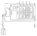
- the autonomously aided GNSS receiver (210) comprises a radio frequency (RF) section (202) in which the GNSS signals are acquired, and a digital section (205) comprising a CPU (207) and a non-volatile memory (204).
- the digital section (205) may be shared with a host device, such as a personal navigation device (e.g., a cell phone or a car navigation device).
- the CPU (207) may be implemented in a number of ways without limiting the applicability of the present disclosure. These include, but are not limited to: microprocessors, field programmable gate arrays (FPGAs), or application-specific integrated circuits (ASICs).
- the non-volatile memory (204) is configured to comprise the following sections:
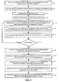
- Figure 3 is a flowchart showing the steps of an embodiment for autonomous prediction of satellite position.
- step (S1) for each satellite, the broadcast ephemeris is obtained from the GNSS broadcast navigation message (101) shown in Figure 2 .
- a GNSS receiver may not be able to observe and record broadcast ephemeris data continuously.
- a sampling scheme can be devised that is consistent with the operational limitation of a GNSS receiver and enables sufficient quantity and distribution of the broadcast data to facilitate accurate prediction of orbit and clocks.
- each broadcast ephemeris record can be expanded into 8 individual records, 15 minutes apart.
- the broadcast ephemeris can be sampled at least three times per day, to ensure optimal GPS constellation sampling.
- a sampling frequency avoiding 24 hour periodicity can be used, until the full constellation is sampled.
- possible sampling intervals could be a 7-hour interval or a 10-hour interval.
- a 7-hour interval would sample the whole GPS constellation in approximately one day, with no 24 hour periodicity for 7 days, but with a near 24 hour periodicity after 3 days.
- a 10-hour interval would sample the whole GPS constellation in approximately 1.5 days, with no 24 hour periodicity for 5 days.
- Such methods can be implemented through software and be stored into non-volatile memory.
- step (S1) All broadcast ephemerides and clock records observed in step (S1) are saved by the receiver (210) in section (206), as shown in Figure 2 . Records older than a certain amount of days (e.g., 14 days) may be discarded.
- step (S2) of Figure 3 the obtained broadcast ephemerides are then converted from Keplerian coordinates into ECEF (Earth-centered-Earth-fixed) Cartesian coordinates according to methods well known in the art and described in the GPS ICD 200, incorporated herein by reference in its entirety and saved in section (206) of the non-volatile memory.
- ECEF Earth-centered-Earth-fixed
- Step (S3) shows generation of a priori EOP (Earth orientation model parameters) values from historical records, for an epoch in the middle of the time span of the broadcast ephemeris.
- the EOP values include UT1-UTC, LOD, X polar motion, X polar motion rate, Y polar motion, and Y polar motion rate.
- a model for predicting the EOP values can be based on a parametric fit to historic time series of measured EOP values, such as those being produced by the International Earth Rotation and Reference Systems Service (IERS).
- the predictive model for each parameter can be generated by performing a power spectrum analysis of the historic time record (spanning nearly 50 years), and selecting the dominant frequencies, together with a long-term quadratic polynomial. Such predictive model can then be used to effectively extrapolate the historic time series into the future.
- This model can be implemented as software stored into section (203) of the receiver of Figure 2 .
- step (S3) The predictive EOP values of step (S3) will be later used as a priori values in the least squares estimation scheme of these and other parameters.
- High accuracy EOP prediction will ensure that the least squares estimation scheme converge to the correct values, and will minimize the data processing time, conserving power.
- the EOP predictive model should be valid for the lifetime of the receiver - typically several years. However, the model can be improved with periodic updates.
- the next step (S4) shown in Figure 3 is that of generating, for each satellite, a) initial orbital position and velocity conditions x(t 0 ), x'(t 0 ) and b) initial orbital dynamic parameters p d .
- the orbital dynamic parameters p d are initialized from the database stored in section (208) of the non-volatile memory (204) of the receiver (210).
- Such iterative estimate can be performed through a least squares fit to ECEF satellite states.
- Such estimation method can be a software method stored into section (203) of the receiver (210).
- the following description of the estimate refers to a single satellite, which can be identified, for example, by its unique pseudorandom noise number (PRN).
- PRN pseudorandom noise number
- Matrix algebra and notations are used.
- the estimation method is aimed at minimizing the square of the distance between the modeled orbit of the satellite and its broadcast ephemeris, both in ECI coordinates, by adjusting the satellite initial conditions, dynamics parameters, and the three EOPs.
- t j be a time point for which a broadcast orbital ephemeris has been obtained for a specific satellite.
- r ej hold the ECEF position coordinates of the satellite as obtained from the broadcast ephemeris at time t j .
- r' ej hold the ECEF velocity coordinates of the satellite as obtained from the broadcast ephemeris.
- T T(t j ,EOP) be a rotation matrix from ECEF to ECI.
- T is a function of time and of the Earth orientation parameters, EOP. In other words, T represents the Earth orientation at each epoch of the broadcast ephemeris.
- An exemplary way of computing T is that of using methods for a) computation of Earth orientation as a function of time and of the EOP (UT1-UTC, LOD, X and Y polar motions, and their rates) and b) computation of the sensitivity of the Earth orientation to the EOP.
- methods a) and b) can follow the 2003 IERS Conventions for modeling of the Earth precession, nutation, polar motion and Earth rotation (see IERS Conventions (2003). Dennis D. McCarthy and whatsoever Petit. Verlag des Bundesamts für Kartographie und Geodäsie, 2004, incorporated herein by reference in its entirety). These methods can be software routines stored into section (203) of the receiver (210).
- the broadcast orbital ephemerides can be converted from ECEF to ECI using the current EOP values and calculating the partial derivatives (sensitivities) of the ECI-converted broadcast orbital ephemeris relative to the current EOP values, as shown in step (S5) of Figure 3 .
- the calculated sensitivities are then stored in the receiver (210).
- x and x' be 3-dimensional vectors, holding the ECI position and velocity, respectively, of the satellite at the first time point, t 1 .
- x can be obtained by T r e1
- x' can be obtained by T r' e1 + T' r e1 .
- the velocities from the broadcast ephemeris are not used, and in that case x' can be obtained by solving the so-called Gauss problem using T r e1 , T r e2 , t 1 , and t 2 (see Bate et al, Fundamental of Astrodynamics, Dover, 1971, Chapter 5.2, pages 227-231 , incorporated herein by reference). Later, x and x' will be estimated and iterated upon.
- p d be a set of m orbital dynamics parameters whose a priori values are not known sufficiently well, but have high impact on the orbital dynamics of the GNSS satellite.
- p d consists of seven parameters: the scale of the solar pressure model (commonly termed "solar scale”), a constant acceleration in a direction perpendicular to the Sun-Earth-Satellite plane (commonly termed "Y-Bias”), four harmonic coefficients representing twice per orbital period accelerations in the radial and cross-track directions, and a constant in-track acceleration.
- p eop be a set of n EOP parameters whose a priori values are not known sufficiently well, but have high impact on the rotation from ECEF frame to ECI frame.
- p eop is provided with three parameters: LOD, X polar motion, and Y polar motion.
- r i is a function of the initial conditions, x, and x', and of the dynamic parameters, p d , and is obtained through integration of the equation of motion from time t 1 to time t j .
- r i depends only weakly on p eop , and therefore this dependency is not specified explicitly.
- a satellite position prediction model is generated starting from the current values of x, x', p d and p eop , as shown in step (S6) of Figure 3 .
- the parameters x, x', p d and p eop are estimated based on such prediction model and the broadcast ephemeris expressed in ECI coordinates, as shown in step (S7) of Figure 3 .
- the above mentioned equation of motion/prediction model can be obtained, for example, through a GNSS orbit model that a) enables the propagation of the satellite trajectory from a set of initial conditions (position and velocity at a given time) and specific model parameters (such as the Earth gravitational constant, satellite mass, etc.) and b) computes the sensitivities of the propagated state to such initial conditions and model parameters.
- a GNSS orbit model can be provided, which integrates the equation of motion and variational equations with sufficient fidelity. The fidelity of the model will directly impact the accuracy of the resulting predicted orbits.
- the GNSS orbit model adopts a 4-5 order, variable step size Runge-Kutta-Fehlberg ordinary differential equation integrator (see, for example. Numerical Recipes, Press et al, Cambridge University Press, 1989, Chapter 15.1-15.2, pages 550-560 , incorporated herein by reference), and the following models of orbital dynamics: point mass attraction for Earth, Sun, and Moon using the JPL Planetary Ephemeris for the relative position of the Earth, Sun, and Moon; Earth gravity field up to degree and order 12; solar pressure model, such as the empirical model of Bar-Sever and Kuang [IPN Progress Report 42-160, JPL, 2004 , http://ipnpr.jpl.nasa.gov/progress_report/42-160/title.htm, incorporated herein by reference in its entirety], which was shown to improve orbit prediction of GPS satellites; a conical Earth and Moon shadow model, such as the model shown in U.S.
- the GNSS orbit model can be implemented as a software routine stored into section (203) of the receiver (210).
- ⁇ d r i is the 3x(6+m) matrix of the sensitivities of r i with respect to x, x', and p d , and is computed by integrating the variational equations of motion (see the model explained above) from time t 1 to time t j . If necessary, ⁇ d r' i is similarly defined and computed by integrating the variational equations of motion.
- Possible approaches can include a method for Housholder orthonormal triangulation, a method for inverting an upper triangular matrix, and a method to combining SRIF arrays using Householder orthogonal transformations [See, for example, from Bierman, Factorization Methods for Discrete Sequential Estimation, Dover, 2006 , incorporated herein by reference]. These algorithms can be stored into the non-volatile memory.
- steps S5 through S7 are repeated until a) the satellite orbits of the last iteration are sufficiently close to the broadcast ephemeris for that satellite or b) the value of the estimated parameters x, x', p d and p eop does not change appreciably from the previous iteration.
- the solved-for 'delta' values are below a certain predetermined threshold, that is, too small to matter, or if the distance between the model and the observations is less than a certain predetermined threshold, the least squares problem is deemed to have converged, and the iteration process is stopped.
- this least squares parameter estimation problem is solved for one satellite in each orbital plane, resulting in six satellites in the case of GPS (which has six orbital planes).
- Other embodiments may solve the problem for a different selection of satellites, trading CPU time and solution accuracy.
- the least squares estimation problem will yield a vastly different set of dynamic parameters, p d , for each satellite.
- the estimated values of the EOP parameters may also be different.
- the estimated value, together with the full covariance matrix from each satellite can be combined using the SRIF factorization approach described above, as shown in step (S9) of Figure 3 . This results in a single, robust, estimate of the EOP values.
- the least squares problem for all satellites can be formed and solved, now estimating only the initial condition parameters x, x' and the dynamic parameters p d , and holding the EOPs fixed to their final, combined, estimated values. This is also shown in step (S10) of Figure 3 .
- the result of this process will be a set of initial conditions (x, x') and dynamic parameters, p d , for all satellites. These ingredients will allow propagation of the orbits of these satellites into the future (with the model explained above), as also shown in steps (S11) through (S13) of Figure 3 .
- These values will be stored in the non-volatile memory (104) in the receiver. Such values represent the predicted orbits that can be used to assist in signal acquisition and positioning.
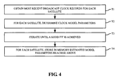
- FIG. 4 shows a flowchart of a method to predict satellite clock states in accordance with an embodiment of the present disclosure.
- step (T1) the most recent broadcast clock records for each satellite are loaded from memory. In a favored embodiment these records span at least one day.
- step (T2) for each satellite, clock model parameters are determined by fitting the clock model to the broadcast ephemeris value.
- the nominal model of the GNSS clock is quadratic in time plus a once-per revolution harmonic, resulting in 5 model parameters per satellite (3 for the quadratic polynomial and 2 for the sine and cosine components of the once-per-revolution harmonic).
- These model parameters can be estimated using a least squares fit of the model to several days of observed clock values extracted from the broadcast ephemeris. See iteration step (T3) of Figure 4 .
- the model for each satellite can be propagated forward indefinitely to produce the predicted clock values, as shown in step (T4) of Figure 4 .
- the estimated model parameters for each satellite are stored in the memory (204) of the receiver (210). They can be invoked to generate clock predictions at any time.
- 4 days of broadcast clock values can be used in the least squares fit to the model. Since clock jumps inconsistent with the model can be occasionally introduced by the GNSS operators, the least squares fit error (root mean square -RMS) can be checked against a predetermined threshold, nominally 1 meter. If the RMS fit exceeds the threshold, the most latent 12 hour segment of the fit interval can be removed in attempt to produce an interval without model inconsistencies. This process can be repeated until the fit RMS is below the threshold, or if the fit interval is less than 12 hours. For fit intervals less than 2 days a linear clock model should be applied (2 parameters per satellite). As usual, such algorithmic model can be stored into section (203) of the receiver (210).
- the propagated orbit and the predicted clock model are available to assist the receiver in the acquisition of future GNSS signals.
- This prediction process can be repeated whenever new ephemeris data records become available, subject to receiver power management considerations and other operational trades.
- the receiver according to the present disclosure will comprise a non-volatile memory section (204) containing:
- GNSS Global Navigation Satellite Systems
- GNSS satellite clock states are also extracted from the broadcast ephemeris and a parametrized model of clock behavior is fit to that data.
- the estimated modeled clocks are then propagated forward in time to enable, together with the predicted orbits, quicker GNSS signal acquision.
Description
- The invention described herein was made in the performance of work under a NASA contract, and is subject to the provisions of Public Law 96-517 (35 USC 202) in which the Contractor has elected to retain title.
- The present disclosure relates to satellite based positioning systems and methods. More particularly, it relates to methods and apparatus for the prediction of satellite ephmerides (comprising orbit and clock states) using the broadcast ephemeris directly obtained from Global Navigation Satellites, without any external data communications.
- The navigation signals from Global Navigation Satellite Systems (GNSS), such as the Global Positioning System (GPS) and GLONASS, are used by GNSS receivers to provide position, navigations and timing (PNT) services, and many related applications.
- As shown in
Figure 1 , a GNSS receiver (110) typically comprises a radio frequency (RF) section (102) and a digital section (105). The digital section (105) further comprises a central processing unit (CPU) (107) and a memory (104). Some GNSS receivers share the digital section with a host device, such as a cell phone, or a personal navigation device. - To perform its basic positioning function, which underlies nearly all PNT applications, a GNSS receiver first acquires the GNSS navigation signal (101) from a sufficient number of GNSS satellites (100), and then extracts from the signal (101) the necessary navigation information. The acquisition of the GNSS signal is carried out in the RF section (102), and the extraction of the navigation information is carried out in the digital section (105). The navigation information embedded in the GNSS navigation signal, and required for positioning, comprises i) the range from the receiver to the transmitting satellites (also known as Pseudo Range because it depends on the inaccurate knowledge of the satellite and receiver clocks, which must later be adjusted using information about the GNSS satellite clock states from the broadcast navigation message, and a least squares estimation of the receiver clock state), and ii) the location, velocity, and clock state of the transmitting satellites. Using data i) and ii), the receiver can triangulate its position using a least squares or similar estimation approach.
- An important metric of receiver performance is the time to first fix (TTFF). This metric measures how long it takes a receiver to acquire the GNSS signals and estimate its position under a variety of conditions, including cold start, i.e., in the absence of any prior accurate knowledge of its position or time or of the current state of the GNSS satellites. For best user experience it is desirable that TTFF be minimized. A significant portion of TTFF from cold start (or even from 'warm start', where partial relevant a priori information is available) is spent by the receiver's RF section (102) in acquiring the GNSS signals, and an additional time is spent in the digital section (105) in extracting the satellite position and clock state information from the navigation message portion of the GNSS navigation signal.
- The time-consuming aspect of the signal acquisition stems from the need to scan the full possible space of range and Doppler values for the desirable signal. The actual speed with which any particular GNSS receiver acquires the GNSS navigation signals strongly depends on its design, its location and its environment.
- After the signals have been acquired by the RF section (102), the navigation information has to be extracted in another time-consuming step. For example, the GPS navigation message is encoded as a 50 bits per second binary data stream, and the precise broadcast ephemeris data containing the needed information about the satellite orbit and clock states are spread over a 1500-bit frame (sequence of bits), requiring the receiver (110) to spend up to 30 seconds to extract all the necessary broadcast ephemeris information.
- The common approaches to reduce TTFF for GNSS receivers revolve around 'aiding' the receiver with external information. Such information typically takes the form of expected orbit and clock states for the GNSS satellites. With additional a priori information, crude as it may be, of its position and/or clock state, the receiver can narrow the search range and Doppler search space for the GNSS signals and acquire them more quickly. If the aided GNSS orbit and clock states (together called the satellite ephemerides) thus provided to the receiver are sufficiently accurate, they can obviate the need to extract the equivalent information from the navigation signal, further reducing TTFF.
- Two basic approaches have been employed for the provision of this type of aid to the receiver (110). The first approach is to provide the receiver (110) in near-real-time with the GNSS orbit and clock states as they are being observed concurrently by a neighboring receiver, or by a network of receivers. This approach requires a continuous, low-latency communications channel, with a fairly high bandwidth, between the monitoring receiver(s), a sequence of servers to collect, process, and disseminate the useful information, and the targeted receiver, which could be, for example, a cell phone or a car navigation device anywhere in the word, or a satellite in low Earth orbit. The second approach being employed is to periodically transfer to the targeted receiver a set of orbit and clock states for the GNSS satellites that are valid over an extended period of time into the future, thus reducing the demands on the required external communications channels. These extended orbit and clock states are calculated by external servers using the broadcast ephemeris and/or range measurements collected over time from a network of GNSS tracking receivers. This latter approach was employed by JPL as early as 1992 in aiding the GPS receiver on the Topex satellite reduce its TTFF. This approach is predicated on the ability to predict, or extend, the GNSS orbit and clock states into the future from past or current information. These ephemerides (comprising the orbit and clock states) are known as 'predicted' or 'extended' ephemerides. In a variant of the latter approach, a server periodically calculates the initial conditions, or 'seeds' of the extended orbit and clock states, and sends only these seeds to the receiver, reducing the needed communications bandwidth. The receiver then generates the extended ephemeris from the seeds using a stored model of the satellite orbit and clock dynamics.
- Regardless of the aiding approach, whether with near-real-time ephemeris or related information (such as the full GNSS navigation message), or with extended ephemeris or related information (such as seeds for an extended ephemeris model), they all require a considerable external infrastructure including a network of tracking receivers, servers, and some sort of communications channels between the targeted receiver and the servers of the aiding information. All of these must operate continuously and reliably, and incur significant cost for equipment, real-estate, communications fees, and human monitoring and maintenance.
- The trajectory of GNSS satellites, such as GPS and GLONASS, is affected by many physical factors which are not perfectly known, or that are not completely predictable, such as the gravitational attraction of the Earth and the flux of the solar radiation. It is therefore difficult to predict the trajectory of these satellites into the future, and invariably, the accuracy of such predictions degrades with time. It is even harder to predict the state of the atomic clocks on these satellites, as they are subject to both random processes and complex environmental effects (temperature, for example). In addition, the satellites' trajectories and clock states can occasionally be altered by their operators, rendering useless any orbit and clock state prediction. For these reasons, the predicted ephemeris must be updated periodically at fairly regular intervals. These intervals are typically governed by the quality of the satellite clock prediction (which is the quantity hardest to predict), and usually varies from sub-daily to weekly, depending on the receiver's positioning accuracy requirements, and the quality of the orbit and clock prediction algorithms.
- There are two basic approaches for predicting the orbit and clock states. The least accurate approach is to obtain a satellite state (orbit and clock) representation at a given time, and propagate it forward with an a priori model. A second, more accurate approach, uses a time series of the satellite or clock states and fits to it a set of model parameters. For the orbit, these model parameters include three initial position coordinates, three initial velocity coordinates, and several physical and empirical parameters of the satellite dynamics, such as solar pressure scale, and constant accelerations. Once these model parameters are estimated, the model can be propagated numerically forward, yielding higher fidelity predicted orbits. A similar process is followed to optimize clock prediction. The time series of orbit and clock states to which the model parameters are fit could be based on accurate data as obtained, for example, from a network-based GNSS orbit determination, or on less accurate data obtained, for example, from the broadcast ephemerides. Regardless, the dominant error source in GNSS orbit and clock predictions is due to uncertainty in the propagation model. The accuracy of the source for the data to fit, whether the broadcast ephemerides or precise ephemerides, is relatively unimportant.
- The physical models governing the motion of satellites are best described in a coordinate system that is fixed in inertial space (Earth-centered-inertial - ECI). Consequently, orbit propagation for GNSS satellites is carried out in an ECI coordinate system. However, a terrestrial GNSS receiver requires position information in a coordinate system rotating with the Earth (Earth-centered-Earth-fixed - ECEF), as indeed provided by the GNSS broadcast ephemeris. Therefore, the predicted orbit should be transformed from ECI to ECEF coordinates before it can be used for receiver aiding, and this requires the knowledge of the Earth orientation in inertial space at any given time. However, the Earth orientation follows a highly complex and unpredictable pattern. Earth orientation is observed and reported after elaborate data processing operations using the geodetic techniques of Very Long Baseline Interferometry (VLBI), and GPS. The three key Earth orientation model parameters (EOP), X and Y polar motion, and Length of Day (LOD) are reported periodically by a few agencies, such as NASA-JPL, the International Earth Rotation and Reference Systems Service (IERS), or the National Geo-spatial Agency (NGA), and are used universally to describe the Earth orientation, and enable the transformation between ECI and ECEF coordinate systems. The dependency on these external sources of periodic Earth orientation is currently one of the insurmountable obstacles to accurate, long-term, in-receiver autonomous ephemeris prediction and aiding.
- An exemplary reference relating to methods and systems for enabling a standalone navigation receiver to generate receiver specific predicted satellite orbits based on historical navigation data collected by and stored in the receiver is
US 2008/0111738 to Han , entitled "Method and Apparatus in Standalone Positioning without Broadcast Ephemeris" and published on May 15, 2008. - Exemplary references relating to a method for determining position of satellites in a satellite navigation system is
FR 2 892 828 US 2008/0288168 to Van Den Bossche , entitled "Method for Determining the Position of Satellites in a Navigation System". The references provide exemplary solutions for transferring data into a coordinate system related to the Earth. - The present disclosure removes the need for any external infrastructure and operations, with their attendant high cost, by enabling the receiver to autonomously generate the extended orbits and clock states to aid signal acquisition and reduce TTFF.
- According to a first aspect, a method to autonomously predict satellite orbit information in Earth-centered-Earth-fixed (ECEF) coordinates for aiding a satellite receiver is provided, as defined by the appended claims.
- According to a second aspect, a method to autonomously predict satellite clock states is provided, comprising: obtaining broadcast clock records for the satellite; iteratively estimating future clock states of the satellite based on a prediction model, until convergence is obtained; and storing the estimated clock states for autonomous prediction of the satellite clock states.
- According to a third aspect, a Global Navigation Satellite System (GNSS) receiver is provided, as defined by appended the claims.
- Further embodiments are shown in the written specification, drawings and claims of the present application.
- Therefore, according to the present disclosure, the need for any communications channels other than the receiver's inherent GNSS RF receiving capability, external infrastructure and operations are removed.
- The method according to the present disclosure lends itself to applications on devices such as cell-phone hosted GNSS receivers, personal navigation devices, vehicle navigation devices, and GNSS receivers in Earth orbit.
- A first advantage of the present disclosure is that the time to first fix (TTFF) is reduced.
- A further advantage of the present disclosure is represented by the frequency and timing of collecting samples of broadcast ephemerides by the receiver, minimizing the required power and memory resources, and maximizing prediction accuracy.
- Another advantage of the present disclosure is that orbits for GNSS satellites in an Earth-Centered-Earth-Fixed (ECEF) reference frame are accurately and efficiently predicted many days into the future based on a limited time span of archived records of satellite ECEF orbital states, as can be obtained from the GNSS broadcast ephemeris or from precise orbit determination solutions.
- Moreover, the Earth orientation parameters (EOP) of X polar motion, Y polar motion, and length of day (LOD) are accurately and efficiently estimated based solely on a limited time span of archived records of satellite ECEF orbital states.
- Additionally, the value of the EOP parameters of X polar motion, Y polar motion, length of day (LOD), and UT1 - UTC (UT1 minus UTC, which is the difference between the UTC time scale defined by atomic standards, and the UT1 time scale, defined by the rotation of the Earth) is predicted several years into the future from a historic observed records of these parameters.
- Still further, clock states of GNSS satellites can be accurately predicted many days into the future based on a limited time span of archived records of satellite clock states, as can be obtained from the GNSS broadcast ephemeris or from precise clock determination solutions
-
-
Figure 1 shows a block diagram of a typical GNSS receiver. -
Figure 2 shows a block diagram of the receiver elements for autonomous predicted orbit and clock aiding according to the present disclosure. -
Figure 3 shows a flow chart of the orbit propagation process according to the present disclosure. -
Figure 4 shows a flow chart of the clock propagation process according to the present disclosure. - According to the present disclosure, devices and methods are described for autonomously providing signal acquisition aiding to a GNSS receiver with predicted GNSS orbit and clock states, using only inherent receiver resources, and without the need for externally-provided information other than factory-installed information.
- As shown in
Figure 2 , the autonomously aided GNSS receiver (210) according to the present disclosure comprises a radio frequency (RF) section (202) in which the GNSS signals are acquired, and a digital section (205) comprising a CPU (207) and a non-volatile memory (204). The digital section (205) may be shared with a host device, such as a personal navigation device (e.g., a cell phone or a car navigation device). The CPU (207) may be implemented in a number of ways without limiting the applicability of the present disclosure. These include, but are not limited to: microprocessors, field programmable gate arrays (FPGAs), or application-specific integrated circuits (ASICs). - The non-volatile memory (204) is configured to comprise the following sections:
- 1) A section (203) for orbit and clock predictions according to the methods and routines later discussed with reference to
Figure 3 andFigure 4 . - 2) A section (206) containing the most recently recorded broadcast ephemerides and clock states.
- 3) A database (208) of Earth orientation values and orbital dynamic parameters.
- 4) A section (209) containing the predicted orbit and clock states obtained as a result of applying the methods later described with reference to
Figure 3 andFigure 4 . -
Figure 3 is a flowchart showing the steps of an embodiment for autonomous prediction of satellite position. - As shown in step (S1), for each satellite, the broadcast ephemeris is obtained from the GNSS broadcast navigation message (101) shown in
Figure 2 . - Due to power constraints or other operational limitations, a GNSS receiver may not be able to observe and record broadcast ephemeris data continuously. In order to overcome such problem, a sampling scheme can be devised that is consistent with the operational limitation of a GNSS receiver and enables sufficient quantity and distribution of the broadcast data to facilitate accurate prediction of orbit and clocks.
- To maximize the utility of the of the broadcast ephemeris records, taking advantage of their two-hours interval of validity (in case of GPS; for other GNSS systems the interval of validity may be different), and without loss of accuracy, each broadcast ephemeris record can be expanded into 8 individual records, 15 minutes apart.
- It should also be noted that at any given time, a terrestrial receiver sees only a fraction of the full GNSS constellation (roughly 30% of the GPS satellites visible from that geographic location at any given time) and that GPS satellites ground tracks tend to repeat every day. In accordance with an embodiment of the present disclosure, the broadcast ephemeris can be sampled at least three times per day, to ensure optimal GPS constellation sampling. Alternatively, a sampling frequency avoiding 24 hour periodicity can be used, until the full constellation is sampled. Such alternative embodiment also overcomes the weakening of the observability of the EOPs which would occur in case of a 24 hour sampling periodicity. According to such embodiment, possible sampling intervals could be a 7-hour interval or a 10-hour interval. A 7-hour interval would sample the whole GPS constellation in approximately one day, with no 24 hour periodicity for 7 days, but with a near 24 hour periodicity after 3 days. A 10-hour interval would sample the whole GPS constellation in approximately 1.5 days, with no 24 hour periodicity for 5 days. Such methods can be implemented through software and be stored into non-volatile memory.
- The person skilled in the art will also understand that any additional broadcast records that can be opportunistically obtained due to unplanned receiver operations can be used to enhance the solutions.
- All broadcast ephemerides and clock records observed in step (S1) are saved by the receiver (210) in section (206), as shown in
Figure 2 . Records older than a certain amount of days (e.g., 14 days) may be discarded. - As shown in step (S2) of
Figure 3 , the obtained broadcast ephemerides are then converted from Keplerian coordinates into ECEF (Earth-centered-Earth-fixed) Cartesian coordinates according to methods well known in the art and described in the GPS ICD 200, incorporated herein by reference in its entirety and saved in section (206) of the non-volatile memory. - Step (S3) shows generation of a priori EOP (Earth orientation model parameters) values from historical records, for an epoch in the middle of the time span of the broadcast ephemeris. The EOP values include UT1-UTC, LOD, X polar motion, X polar motion rate, Y polar motion, and Y polar motion rate.
- By way of example and not of limitation, a model for predicting the EOP values can be based on a parametric fit to historic time series of measured EOP values, such as those being produced by the International Earth Rotation and Reference Systems Service (IERS). The predictive model for each parameter can be generated by performing a power spectrum analysis of the historic time record (spanning nearly 50 years), and selecting the dominant frequencies, together with a long-term quadratic polynomial. Such predictive model can then be used to effectively extrapolate the historic time series into the future. This model can be implemented as software stored into section (203) of the receiver of
Figure 2 . - The predictive EOP values of step (S3) will be later used as a priori values in the least squares estimation scheme of these and other parameters. High accuracy EOP prediction will ensure that the least squares estimation scheme converge to the correct values, and will minimize the data processing time, conserving power. To ensure complete autonomy, the EOP predictive model should be valid for the lifetime of the receiver - typically several years. However, the model can be improved with periodic updates.
- The next step (S4) shown in
Figure 3 is that of generating, for each satellite, a) initial orbital position and velocity conditions x(t0), x'(t0) and b) initial orbital dynamic parameters pd. - As later shown in the present disclosure, such EOP (S3) orbital conditions (S4) and dynamic parameters (S4) will be iteratively estimated. The following paragraphs will describe a method to perform such iterative estimate, in accordance with an embodiment of the present disclosure. The orbital dynamic parameters pd are initialized from the database stored in section (208) of the non-volatile memory (204) of the receiver (210).
- In particular, such iterative estimate can be performed through a least squares fit to ECEF satellite states. Such estimation method can be a software method stored into section (203) of the receiver (210). For the sake of simplicity, the following description of the estimate refers to a single satellite, which can be identified, for example, by its unique pseudorandom noise number (PRN). Matrix algebra and notations are used. The estimation method is aimed at minimizing the square of the distance between the modeled orbit of the satellite and its broadcast ephemeris, both in ECI coordinates, by adjusting the satellite initial conditions, dynamics parameters, and the three EOPs.
- Let tj be a time point for which a broadcast orbital ephemeris has been obtained for a specific satellite. The index j counts the ephemeris time points, j=1,2,...N. Let rej hold the ECEF position coordinates of the satellite as obtained from the broadcast ephemeris at time tj. Let r'ej hold the ECEF velocity coordinates of the satellite as obtained from the broadcast ephemeris. Let Sj be the assumed error of the broadcast ephemeris position at each time tj. According to an embodiment of the present disclosure, Sj = 1 meter for all j. Let s'j be the assumed error of the broadcast ephemeris velocity at each time tj. For example, let s'j = 0.001 meter/sec for all j. Let T = T(tj,EOP) be a rotation matrix from ECEF to ECI. T is a function of time and of the Earth orientation parameters, EOP. In other words, T represents the Earth orientation at each epoch of the broadcast ephemeris.
- An exemplary way of computing T is that of using methods for a) computation of Earth orientation as a function of time and of the EOP (UT1-UTC, LOD, X and Y polar motions, and their rates) and b) computation of the sensitivity of the Earth orientation to the EOP. For example, methods a) and b) can follow the 2003 IERS Conventions for modeling of the Earth precession, nutation, polar motion and Earth rotation (see IERS Conventions (2003). Dennis D. McCarthy and Gérard Petit. Verlag des Bundesamts für Kartographie und Geodäsie, 2004, incorporated herein by reference in its entirety). These methods can be software routines stored into section (203) of the receiver (210).
- Therefore, the broadcast orbital ephemerides can be converted from ECEF to ECI using the current EOP values and calculating the partial derivatives (sensitivities) of the ECI-converted broadcast orbital ephemeris relative to the current EOP values, as shown in step (S5) of
Figure 3 . The calculated sensitivities are then stored in the receiver (210). - Turning back to the iterative estimate method, let x and x' be 3-dimensional vectors, holding the ECI position and velocity, respectively, of the satellite at the first time point, t1. Initially x can be obtained by T re1, and x' can be obtained by T r'e1 + T' re1. In one embodiment of the method according to the present disclosure, the velocities from the broadcast ephemeris are not used, and in that case x' can be obtained by solving the so-called Gauss problem using T re1, T re2, t1, and t2 (see Bate et al, Fundamental of Astrodynamics, Dover, 1971, Chapter 5.2, pages 227-231, incorporated herein by reference). Later, x and x' will be estimated and iterated upon.
- Let pd be a set of m orbital dynamics parameters whose a priori values are not known sufficiently well, but have high impact on the orbital dynamics of the GNSS satellite. According to one of the embodiments of the present disclosure. pd consists of seven parameters: the scale of the solar pressure model (commonly termed "solar scale"), a constant acceleration in a direction perpendicular to the Sun-Earth-Satellite plane (commonly termed "Y-Bias"), four harmonic coefficients representing twice per orbital period accelerations in the radial and cross-track directions, and a constant in-track acceleration.
- Let peop be a set of n EOP parameters whose a priori values are not known sufficiently well, but have high impact on the rotation from ECEF frame to ECI frame. In one of the embodiments of the present disclosure, peop is provided with three parameters: LOD, X polar motion, and Y polar motion.
- Let ri = ri (x,x',pd) be the modeled ECI position coordinates of the satellite at time tj. ri is a function of the initial conditions, x, and x', and of the dynamic parameters, pd, and is obtained through integration of the equation of motion from time t1 to time tj. ri depends only weakly on peop, and therefore this dependency is not specified explicitly. Similarly, let r'i = r'i (x,x',pd) be the modeled ECI velocity coordinates of the satellite at time tj. When the velocity coordinates are not extracted from the broadcast ephemeris, they will also not be modeled.
- Therefore, a satellite position prediction model is generated starting from the current values of x, x', pd and peop, as shown in step (S6) of
Figure 3 . Once this is done, the parameters x, x', pd and peop are estimated based on such prediction model and the broadcast ephemeris expressed in ECI coordinates, as shown in step (S7) ofFigure 3 . - The above mentioned equation of motion/prediction model can be obtained, for example, through a GNSS orbit model that a) enables the propagation of the satellite trajectory from a set of initial conditions (position and velocity at a given time) and specific model parameters (such as the Earth gravitational constant, satellite mass, etc.) and b) computes the sensitivities of the propagated state to such initial conditions and model parameters. Stated differently, a GNSS orbit model can be provided, which integrates the equation of motion and variational equations with sufficient fidelity. The fidelity of the model will directly impact the accuracy of the resulting predicted orbits. According to one of the embodiments of the disclosure, the GNSS orbit model adopts a 4-5 order, variable step size Runge-Kutta-Fehlberg ordinary differential equation integrator (see, for example. Numerical Recipes, Press et al, Cambridge University Press, 1989, Chapter 15.1-15.2, pages 550-560, incorporated herein by reference), and the following models of orbital dynamics: point mass attraction for Earth, Sun, and Moon using the JPL Planetary Ephemeris for the relative position of the Earth, Sun, and Moon; Earth gravity field up to degree and order 12; solar pressure model, such as the empirical model of Bar-Sever and Kuang [IPN Progress Report 42-160, JPL, 2004, http://ipnpr.jpl.nasa.gov/progress_report/42-160/title.htm, incorporated herein by reference in its entirety], which was shown to improve orbit prediction of GPS satellites; a conical Earth and Moon shadow model, such as the model shown in
U.S. Pat. Nos. 5,963,167 , and5,828,336 ; a satellite attitude model such as the model shown inU.S Pat. No. 6,295,021 for GPS satellites ; RF thrust model; and relativity models. The GNSS orbit model can be implemented as a software routine stored into section (203) of the receiver (210). - Turning back to the iterative estimate, for notation purposes, let d be the composite (6+m)-dimensional vector comprising of x, x', and pd. That is: dt = [xt; x't; pd], where superscript t indicates the transpose operation. Let ∇d be the dynamics gradient operator, defined as follows:

- ∇dri, then, is the 3x(6+m) matrix of the sensitivities of ri with respect to x, x', and pd, and is computed by integrating the variational equations of motion (see the model explained above) from time t1 to time tj. If necessary, ∇dr'i is similarly defined and computed by integrating the variational equations of motion. Let ∇eop be the EOP gradient operator, defined as follows:

where ∇eopT can be computed by the above described method of obtaining T. - The least squares problem can now be formulated as follows: find the set of parameters d, and peop, that minimizes, in least square sense, the distance between the observed position in ECI frame, T rej, and the modeled position in ECI frame, rj, for j=1,...N. To solve this problem numerically, the problem is linearized around the a priori values of the solved-for parameters d and peop, and the resulting linear least squares problem solved to find the adjustments, Δd and Δpeop, for these parameters. The least squares solution is then iterated by re-linearizing the problem around the adjusted values of the solved-for parameters, and so on, until the solution converges. The linear least squares problem is now:

- Isolating the unknowns on the left hand side results with the classical formulation of least squares problems:

with the associated data noise Sj. This numerical least squares problem can be solved using a square root information filter (SRIF) factorization approach. Possible approaches can include a method for Housholder orthonormal triangulation, a method for inverting an upper triangular matrix, and a method to combining SRIF arrays using Householder orthogonal transformations [See, for example, from Bierman, Factorization Methods for Discrete Sequential Estimation, Dover, 2006, incorporated herein by reference]. These algorithms can be stored into the non-volatile memory. - As shown in step (S8) of
Figure 3 , steps S5 through S7 are repeated until a) the satellite orbits of the last iteration are sufficiently close to the broadcast ephemeris for that satellite or b) the value of the estimated parameters x, x', pd and peop does not change appreciably from the previous iteration. In other words, if the solved-for 'delta' values are below a certain predetermined threshold, that is, too small to matter, or if the distance between the model and the observations is less than a certain predetermined threshold, the least squares problem is deemed to have converged, and the iteration process is stopped. If these conditions are not met, and if the number of iterations does not exceed a certain predetermined threshold, the least squares problem is iterated with the new nominal parameter values: d = d + Δd, and peop = peop + Δpeop. - According to one embodiment of the present disclosure, this least squares parameter estimation problem is solved for one satellite in each orbital plane, resulting in six satellites in the case of GPS (which has six orbital planes). Other embodiments may solve the problem for a different selection of satellites, trading CPU time and solution accuracy. It is expected that the least squares estimation problem will yield a vastly different set of dynamic parameters, pd, for each satellite. However, the estimated values of the EOP parameters, may also be different. To improve the accuracy of the estimated value of EOP parameters, peop, the estimated value, together with the full covariance matrix from each satellite can be combined using the SRIF factorization approach described above, as shown in step (S9) of
Figure 3 . This results in a single, robust, estimate of the EOP values. - Once the values of the uncertain EOPs, peop, have been robustly estimated, the least squares problem for all satellites can be formed and solved, now estimating only the initial condition parameters x, x' and the dynamic parameters pd, and holding the EOPs fixed to their final, combined, estimated values. This is also shown in step (S10) of
Figure 3 . The result of this process will be a set of initial conditions (x, x') and dynamic parameters, pd, for all satellites. These ingredients will allow propagation of the orbits of these satellites into the future (with the model explained above), as also shown in steps (S11) through (S13) ofFigure 3 . These values will be stored in the non-volatile memory (104) in the receiver. Such values represent the predicted orbits that can be used to assist in signal acquisition and positioning. - Reference will now be made to
Figure 4 , which shows a flowchart of a method to predict satellite clock states in accordance with an embodiment of the present disclosure. - As shown in step (T1), the most recent broadcast clock records for each satellite are loaded from memory. In a favored embodiment these records span at least one day. In step (T2), for each satellite, clock model parameters are determined by fitting the clock model to the broadcast ephemeris value.
- The nominal model of the GNSS clock is quadratic in time plus a once-per revolution harmonic, resulting in 5 model parameters per satellite (3 for the quadratic polynomial and 2 for the sine and cosine components of the once-per-revolution harmonic). These model parameters can be estimated using a least squares fit of the model to several days of observed clock values extracted from the broadcast ephemeris. See iteration step (T3) of
Figure 4 . Once the model parameters have been estimated individually for each satellite, the model for each satellite can be propagated forward indefinitely to produce the predicted clock values, as shown in step (T4) ofFigure 4 . The estimated model parameters for each satellite are stored in the memory (204) of the receiver (210). They can be invoked to generate clock predictions at any time. According to one embodiment of the present disclosure, 4 days of broadcast clock values can be used in the least squares fit to the model. Since clock jumps inconsistent with the model can be occasionally introduced by the GNSS operators, the least squares fit error (root mean square -RMS) can be checked against a predetermined threshold, nominally 1 meter. If the RMS fit exceeds the threshold, the most latent 12 hour segment of the fit interval can be removed in attempt to produce an interval without model inconsistencies. This process can be repeated until the fit RMS is below the threshold, or if the fit interval is less than 12 hours. For fit intervals less than 2 days a linear clock model should be applied (2 parameters per satellite). As usual, such algorithmic model can be stored into section (203) of the receiver (210). - At the end of the prediction process, the propagated orbit and the predicted clock model are available to assist the receiver in the acquisition of future GNSS signals. This prediction process can be repeated whenever new ephemeris data records become available, subject to receiver power management considerations and other operational trades.
- As described above, and as also mentioned with reference to
Figure 2 , according to one of the embodiments of the present disclosure, the receiver according to the present disclosure will comprise a non-volatile memory section (204) containing: - 1) the object code for the various software routines discussed above, such as: i) the EOP predictive model; ii) the methods for producing the rotation matrix; iii) the GNSS orbit model integrating the equations of motion: iv) the SRIF algorithms; v) the method for iterative estimate of the orbital initial conditions, dynamic parameters and EOPs; vi) the method for clock prediction; and vii) the method for optimal sampling of GNSS broadcast ephemeris data.
- 2) the most recently recorded broadcast ephemerides.
- 3) a database of orbital dynamic parameters d for initialization purposes.
- 4) a priori EOP values generated through the EOP predictive model above.
- 5) predicted orbit and clock states obtained as a result of applying the methods described in 1) above.
- In summary, according to some embodiments of the present disclosure, methods and apparatus for autonomous in-receiver prediction of orbit and clock states of Global Navigation Satellite Systems (GNSS) arc described. Only the GNSS broadcast message is used, without need for periodic externally-communicated information. Earth orientation information is extracted from the GNSS broadcast ephemeris. With the accurate estimation of the Earth orientation parameters it is possible to propagate the best-fit GNSS orbits forward in time in an inertial reference frame. Using the estimated Earth orientation parameters, the predicted orbits are then transformed into Earth-Centered-Earth-Fixed (ECEF) coordinates to be used to assist the GNSS receiver in the acquision of the signals. GNSS satellite clock states are also extracted from the broadcast ephemeris and a parametrized model of clock behavior is fit to that data. The estimated modeled clocks are then propagated forward in time to enable, together with the predicted orbits, quicker GNSS signal acquision.
- Accordingly, what has been shown are methods and apparatus for autonomous, in-receiver prediction of GNSS ephemerides. While the methods and apparatus have been described by means of specific embodiments and applications thereof, it is understood that numerous modifications and variations could be made thereto by those skilled in the art without departing from the scope of the disclosure. It is therefore to be understood that within the scope of the claims, the disclosure may be practiced otherwise than as specifically described herein.
Claims (25)
- A method to autonomously predict satellite orbit information in Earth-centered-Earth-fixed (ECEF) coordinates for aiding a satellite receiver, comprising:i) obtaining (S1) a broadcast orbital ephemeris of the satellite;ii) generating (S3) an initial set of Earth orientation parameters (EOP) from historical observation records based on a model for predicting EOP values;iii) generating (S4) an initial set of satellite initial conditions and an initial set of orbital dynamic parameters;iv) iteratively estimating (S7) Earth orientation parameters (EOP), satellite initial conditions, and orbital dynamic parameters by using a satellite position prediction model, the broadcast orbital ephemeris expressed in Earth-centered-inertial (ECI) coordinates, the initial set of Earth orientation parameters (EOP), the initial set of satellite initial conditions, and the initial set of orbital dynamic parameters until convergence (S8) is obtained;v) obtaining (S11) predicted orbits by propagating forward in time the estimated Earth orientation parameters (EOP), the estimated satellite initial conditions, and the estimated orbital dynamic parameters;vi) converting (S12) the predicted orbits to Earth-centered-Earth-fixed (ECEF) coordinates by using the estimated Earth orientation parameters (EOP); andvii) storing (S 13) the converted predicted orbits.
- The method of claim 1, wherein orbit information of a plurality of satellites is autonomously predicted by applying steps i) through vii) to the plurality of satellites.
- The method of claim 1 or 2, wherein EOP values and their covariance matrix estimated from one satellite data, are optimally combined with estimates of EOP and covariance from other satellites data.
- The method of any one of the previous claims, wherein the EOP comprise X polar motion, Y polar motion, and length of day (LOD).
- The method of any one of the previous claims, further comprising converting (S5) the obtained broadcast orbital ephemeris of the satellite from a first coordinate system to a second coordinate system.
- The method of claim 5, further comprising, during the iterative estimation, calculating sensitivities (S5) of the converted broadcast orbital ephemeris to EOP.
- The method of claim 5 or 6, wherein the first coordinate system is an Earth-centered-Earth-fixed (ECEF) Cartesian coordinate system and the second coordinate system is an Earth-centered-inertial (ECI) coordinate system.
- The method of any one of the previous claims, wherein the satellite and the receiver are part of a Global Navigation Satellite System (GNSS).
- The method of any one of the previous claims, wherein the broadcast ephemeris of the satellite is obtained through a sampling process.
- The method of claim 9, wherein the sampling process occurs at least three times a day.
- The method of claim 9 or 10, wherein the sampling process occurs with a daily periodicity-avoiding sampling frequency.
- The method of claim 11, wherein the sampling frequency is selected from the group consisting of a 7-hour interval sampling frequency, and a 10-hour interval sampling frequency.
- The method of claim 3, wherein the model for predicting EOP values is based on a parametric fit to historic time series of measured EOP values.
- The method of any one of the previous claims, wherein step iv) is performed through a least squares fit to satellite states.
- The method of claim 14, wherein the satellite states are Earth-centered-Earth-fixed (ECEF) satellite states.
- The method of claim 15, wherein the least squares fit is solved through a square root information filter (SRIF) factorization approach.
- The method of any one of the previous claims, wherein convergence (S8) of step iv) is obtained a) when currently estimated satellite orbits of a last iteration are sufficiently close to the broadcast ephemeris for that satellite or b) when the value of currently estimated Earth orientation parameters (EOP), satellite initial conditions, and orbital dynamic parameters does not change appreciably from a previous iteration.
- The method of any one of the previous claims, wherein the predicted orbits are stored in the satellite receiver.
- A method for autonomous prediction of satellite orbit information and satellite clock states, comprising:autonomously predicting satellite orbit information according to the method of any one of claims 1 to 18; andautonomously predicting satellite clock states by performing steps of:i) obtaining (T1) broadcast clock records for the satellite;ii) iteratively estimating (T3) future clock states of the satellite based on a prediction model, until convergence is obtained; andiii) storing (T4) the estimated clock states for autonomous prediction of the satellite clock states.
- The method of claim 19, wherein clock states of a plurality of satellites are autonomously predicted by applying steps i), ii) and iii) to the plurality of satellites.
- The method of claim 19 or 20, wherein the prediction model is quadratic in time plus a once-per revolution harmonic, resulting in five model parameters per satellite.
- A Global Navigation Satellite System (GNSS) receiver comprising:a processing unit (207); anda memory unit (204),wherein the memory unit (204) is configured to comprise:a first memory section (203) storing software code for satellite orbit prediction and satellite clock states prediction;a second memory section (206) storing recorded satellite broadcast orbit and satellite clock states;a third memory section (208) storing Earth orientation parameter (EOP) values and orbital dynamic parameters; anda fourth memory section (209) storing predicted satellite orbits and satellite clock states calculated in accordance with the software code stored in the first memory section (203),wherein the software code for satellite orbit prediction is executable to perform according to the method of claim 1.
- The GNSS receiver of claim 22, wherein the software code for satellite clock states prediction is executable to perform steps of:i) obtaining (T1) broadcast clock records for the satellite;ii) iteratively estimating (T3) future clock states of the satellite based on a prediction model, until convergence is obtained; andiii) storing (T4) the estimated clock states for autonomous prediction of the satellite clock states.
- A personal navigation device comprising the GNSS receiver of claim 22 or 23.
- The personal navigation device of claim 24, said device being a cell phone or a car navigation device.
Applications Claiming Priority (2)
| Application Number | Priority Date | Filing Date | Title |
|---|---|---|---|
| US12/208,525 US8120529B2 (en) | 2008-09-11 | 2008-09-11 | Method and apparatus for autonomous, in-receiver prediction of GNSS ephemerides |
| PCT/US2009/054635 WO2010047875A2 (en) | 2008-09-11 | 2009-08-21 | Method and apparatus for autonomous, in-receiver prediction of gnss ephemerides |
Publications (3)
| Publication Number | Publication Date |
|---|---|
| EP2324371A2 EP2324371A2 (en) | 2011-05-25 |
| EP2324371A4 EP2324371A4 (en) | 2011-12-21 |
| EP2324371B1 true EP2324371B1 (en) | 2012-11-28 |
Family
ID=41798799
Family Applications (1)
| Application Number | Title | Priority Date | Filing Date |
|---|---|---|---|
| EP09822368A Not-in-force EP2324371B1 (en) | 2008-09-11 | 2009-08-21 | Method and apparatus for autonomous, in-receiver prediction of gnss ephemerides |
Country Status (6)
| Country | Link |
|---|---|
| US (1) | US8120529B2 (en) |
| EP (1) | EP2324371B1 (en) |
| JP (1) | JP5355694B2 (en) |
| KR (1) | KR101311354B1 (en) |
| CN (1) | CN102209911B (en) |
| WO (1) | WO2010047875A2 (en) |
Families Citing this family (82)
| Publication number | Priority date | Publication date | Assignee | Title |
|---|---|---|---|---|
| US7948769B2 (en) * | 2007-09-27 | 2011-05-24 | Hemisphere Gps Llc | Tightly-coupled PCB GNSS circuit and manufacturing method |
| US7885745B2 (en) | 2002-12-11 | 2011-02-08 | Hemisphere Gps Llc | GNSS control system and method |
| US8271194B2 (en) | 2004-03-19 | 2012-09-18 | Hemisphere Gps Llc | Method and system using GNSS phase measurements for relative positioning |
| US8265826B2 (en) | 2003-03-20 | 2012-09-11 | Hemisphere GPS, LLC | Combined GNSS gyroscope control system and method |
| US8140223B2 (en) * | 2003-03-20 | 2012-03-20 | Hemisphere Gps Llc | Multiple-antenna GNSS control system and method |
| US9002565B2 (en) | 2003-03-20 | 2015-04-07 | Agjunction Llc | GNSS and optical guidance and machine control |
| US8686900B2 (en) * | 2003-03-20 | 2014-04-01 | Hemisphere GNSS, Inc. | Multi-antenna GNSS positioning method and system |
| US8594879B2 (en) * | 2003-03-20 | 2013-11-26 | Agjunction Llc | GNSS guidance and machine control |
| US8634993B2 (en) | 2003-03-20 | 2014-01-21 | Agjunction Llc | GNSS based control for dispensing material from vehicle |
| US8190337B2 (en) * | 2003-03-20 | 2012-05-29 | Hemisphere GPS, LLC | Satellite based vehicle guidance control in straight and contour modes |
| US8138970B2 (en) * | 2003-03-20 | 2012-03-20 | Hemisphere Gps Llc | GNSS-based tracking of fixed or slow-moving structures |
| US8583315B2 (en) * | 2004-03-19 | 2013-11-12 | Agjunction Llc | Multi-antenna GNSS control system and method |
| USRE48527E1 (en) | 2007-01-05 | 2021-04-20 | Agjunction Llc | Optical tracking vehicle control system and method |
| US7835832B2 (en) * | 2007-01-05 | 2010-11-16 | Hemisphere Gps Llc | Vehicle control system |
| US8311696B2 (en) * | 2009-07-17 | 2012-11-13 | Hemisphere Gps Llc | Optical tracking vehicle control system and method |
| US8000381B2 (en) * | 2007-02-27 | 2011-08-16 | Hemisphere Gps Llc | Unbiased code phase discriminator |
| US7808428B2 (en) * | 2007-10-08 | 2010-10-05 | Hemisphere Gps Llc | GNSS receiver and external storage device system and GNSS data processing method |
| US20100161179A1 (en) * | 2008-12-22 | 2010-06-24 | Mcclure John A | Integrated dead reckoning and gnss/ins positioning |
| US9002566B2 (en) | 2008-02-10 | 2015-04-07 | AgJunction, LLC | Visual, GNSS and gyro autosteering control |
| US8018376B2 (en) | 2008-04-08 | 2011-09-13 | Hemisphere Gps Llc | GNSS-based mobile communication system and method |
| JP2010060383A (en) * | 2008-09-02 | 2010-03-18 | Seiko Epson Corp | Data compression method, data providing method, data recovery method, data compression device and positioning device |
| US8217833B2 (en) * | 2008-12-11 | 2012-07-10 | Hemisphere Gps Llc | GNSS superband ASIC with simultaneous multi-frequency down conversion |
| US8386129B2 (en) | 2009-01-17 | 2013-02-26 | Hemipshere GPS, LLC | Raster-based contour swathing for guidance and variable-rate chemical application |
| US8085196B2 (en) | 2009-03-11 | 2011-12-27 | Hemisphere Gps Llc | Removing biases in dual frequency GNSS receivers using SBAS |
| US8164518B2 (en) * | 2009-06-19 | 2012-04-24 | Broadcom Corporation | Method and system for a GNSS receiver with self-assisted ephemeris extensions |
| US8401704B2 (en) * | 2009-07-22 | 2013-03-19 | Hemisphere GPS, LLC | GNSS control system and method for irrigation and related applications |
| US8174437B2 (en) * | 2009-07-29 | 2012-05-08 | Hemisphere Gps Llc | System and method for augmenting DGNSS with internally-generated differential correction |
| US8334804B2 (en) * | 2009-09-04 | 2012-12-18 | Hemisphere Gps Llc | Multi-frequency GNSS receiver baseband DSP |
| US8649930B2 (en) | 2009-09-17 | 2014-02-11 | Agjunction Llc | GNSS integrated multi-sensor control system and method |
| US9075140B2 (en) * | 2009-09-23 | 2015-07-07 | Purdue Research Foundation | GNSS ephemeris with graceful degradation and measurement fusion |
| US8548649B2 (en) | 2009-10-19 | 2013-10-01 | Agjunction Llc | GNSS optimized aircraft control system and method |
| US20110172887A1 (en) * | 2009-11-30 | 2011-07-14 | Reeve David R | Vehicle assembly control method for collaborative behavior |
| US20110188618A1 (en) * | 2010-02-02 | 2011-08-04 | Feller Walter J | Rf/digital signal-separating gnss receiver and manufacturing method |
| US8583326B2 (en) * | 2010-02-09 | 2013-11-12 | Agjunction Llc | GNSS contour guidance path selection |
| US9007261B2 (en) * | 2010-05-06 | 2015-04-14 | Mediatek Inc. | Method and apparatus for fast TTFF |
| JP2012013506A (en) * | 2010-06-30 | 2012-01-19 | Japan Radio Co Ltd | Positioning support device |
| JP2012013505A (en) * | 2010-06-30 | 2012-01-19 | Japan Radio Co Ltd | Positioning support device |
| US8514128B2 (en) * | 2010-09-02 | 2013-08-20 | eRide,. Inc. | Satellite navigation receivers with self-provided future ephemeris and clock predictions |
| GB2483713B (en) * | 2010-09-20 | 2016-04-06 | St Microelectronics Res & Dev | Signal verification |
| US20140125519A1 (en) * | 2010-11-09 | 2014-05-08 | Alexander Brown | Methods for Encoding and Recovering GNSS Ephemeris For Over-The-Air Transmission |
| CN102109349B (en) * | 2010-12-13 | 2013-03-13 | 北京航空航天大学 | MIMU (Micro Inertial Measurement Unit) system with ECEF (Earth Centered Earth Fixed) model |
| WO2012125293A2 (en) * | 2011-03-11 | 2012-09-20 | Sorce4 Llc. | Offline ephemeris prediction |
| JP5801111B2 (en) * | 2011-06-21 | 2015-10-28 | 日本無線株式会社 | Orbit prediction apparatus and orbit prediction method |
| JP5801110B2 (en) * | 2011-06-21 | 2015-10-28 | 日本無線株式会社 | Orbit prediction apparatus and orbit prediction method |
| CN102424119B (en) * | 2011-10-14 | 2014-04-16 | 北京理工大学 | Interplanetary low-thrust transfer orbit design method based on polynomial approximation |
| JP2014044191A (en) * | 2012-07-31 | 2014-03-13 | Seiko Epson Corp | Position calculation method, and position calculation device |
| KR101329017B1 (en) * | 2012-08-20 | 2013-11-13 | 주식회사 텔에이스 | Satellite position prediction method and gnss receiver |
| WO2014046917A1 (en) * | 2012-09-20 | 2014-03-27 | California Institute Of Technology | Enhanced broadcast ephemeris for high accuracy assisted gps positioning |
| WO2014067013A1 (en) * | 2012-11-04 | 2014-05-08 | Eric Derbez | Low bandwidth method for ephemeris recovery in over-the-air transmission |
| JP2014142222A (en) * | 2013-01-23 | 2014-08-07 | Seiko Epson Corp | Position calculation method and position calculation device |
| US9354322B2 (en) * | 2013-05-15 | 2016-05-31 | General Motors Llc | Configuring Global Navigation Satellite System receiver units via over-the-air communications with control center |
| CN104181555A (en) * | 2013-05-24 | 2014-12-03 | 凹凸电子(武汉)有限公司 | Satellite positioning quality determination method and receiver |
| JP2015021900A (en) * | 2013-07-22 | 2015-02-02 | 日本無線株式会社 | Satellite clock correction parameter generation device and method for the same, and positioning-apparatus |
| JP6191074B2 (en) * | 2013-07-22 | 2017-09-06 | 日本無線株式会社 | Satellite clock accuracy judging device, method and positioning device |
| US9739888B2 (en) * | 2013-09-12 | 2017-08-22 | Marvell World Trade Ltd. | Method, system and device for position determination with predicted ephemeris |
| CN105223597A (en) * | 2014-04-04 | 2016-01-06 | 马维尔国际有限公司 | Based on the method and apparatus of satellite determination communications device locations |
| US9645247B2 (en) * | 2014-07-25 | 2017-05-09 | General Motors Llc | Fast estimation of UTC time in a mobile device using GNSS |
| DE102014219385A1 (en) * | 2014-09-25 | 2016-03-31 | Continental Teves Ag & Co. Ohg | Vehicle-to-X communication module |
| US9877157B2 (en) * | 2014-12-15 | 2018-01-23 | Marvell World Trade Ltd. | Autonomous in-device GNSS augmentation system |
| CN104931993B (en) * | 2015-05-25 | 2017-09-22 | 清华大学 | Miniature location navigation time dissemination system |
| US11187808B2 (en) * | 2015-06-19 | 2021-11-30 | Profound Positioning Inc. | Methods and systems for performing global navigation satellite system (GNSS) orbit and clock augmentation and position determination |
| US10598796B1 (en) | 2015-12-01 | 2020-03-24 | Marvell International Ltd. | Method and apparatus for positioning |
| ITUB20160628A1 (en) | 2016-02-10 | 2017-08-10 | St Microelectronics Srl | PROCEDURE FOR PREDICTING THE ORBIT OF A SATELLITE AND CORRESPONDING SATELLITE SIGNAL RECEIVER |
| GB2548367A (en) | 2016-03-15 | 2017-09-20 | Here Global Bv | Supporting an estimation of satellite locations |
| US10502835B2 (en) * | 2016-03-28 | 2019-12-10 | Uti Limited Partnership | Methods and systems for inherent fast time to first position fix (TTFF) and high sensitivity |
| CN106096787B (en) * | 2016-06-17 | 2019-02-22 | 北京航天飞行控制中心 | A kind of earth rotation parameter (ERP) forecasting procedure of Adaptive matching |
| CN108107458B (en) * | 2016-11-24 | 2021-07-23 | 展讯通信(上海)有限公司 | Method and device for realizing GNSS receiver first positioning and mobile terminal |
| US10795028B2 (en) * | 2016-12-20 | 2020-10-06 | Here Global B.V. | Supporting an extension of a validity period of parameter values defining an orbit |
| AU2017379407B2 (en) * | 2016-12-22 | 2021-01-21 | Myriota Pty Ltd | System and method for generating extended satellite ephemeris data |
| CN108761505B (en) * | 2018-06-04 | 2020-11-10 | 北京未来导航科技有限公司 | Method and system for processing predicted orbit of navigation satellite |
| CN109917431B (en) * | 2019-04-02 | 2021-03-23 | 中国科学院空间应用工程与技术中心 | Method for realizing GNSS satellite autonomous navigation by utilizing DRO orbit and inter-satellite measurement |
| WO2020218626A2 (en) * | 2019-04-25 | 2020-10-29 | Kwan U Kim | Εορ prediction method, εορ prediction apparatus, eop prediction program and computer readable recording media recorded with eop prediction program |
| CN111308515A (en) * | 2019-10-30 | 2020-06-19 | 中海北斗(深圳)导航技术有限公司 | Beidou satellite maneuvering and anomaly detection method based on precise orbit and ground station data |
| US11841444B2 (en) | 2020-08-27 | 2023-12-12 | Sony Group Corporation | Resilient ephemeris decoding of GNSS satellite information |
| CN112666583A (en) * | 2020-12-15 | 2021-04-16 | 上海卫星工程研究所 | Single-shot orbit recursion method and system adaptive to GNSS receiver output state |
| CN112987044B (en) * | 2021-02-25 | 2021-12-10 | 中国科学院微小卫星创新研究院 | Constellation ephemeris on-orbit updating method |
| CN115308779B (en) * | 2021-05-07 | 2023-11-03 | 华为技术有限公司 | Ephemeris forecasting method and ephemeris forecasting device |
| CN113341439B (en) * | 2021-06-22 | 2022-04-15 | 武汉大学 | GNSS station-measuring speed robust estimation method considering periodic signals |
| CN113536547B (en) * | 2021-06-25 | 2023-07-14 | 北京控制工程研究所 | Reliable multi-source track extrapolation independent selection method |
| CN114089618B (en) * | 2021-11-01 | 2022-12-13 | 中国科学院国家授时中心 | Method for observing and detecting atomic clock jump by using single pulsar |
| CN114265093B (en) * | 2021-12-06 | 2023-07-18 | 中国人民解放军海军工程大学 | Satellite clock error forecasting method, system, medium, equipment and terminal |
| CN115102611B (en) * | 2022-08-24 | 2022-10-25 | 青岛杰瑞自动化有限公司 | Method for shortening hot start time of satellite receiver by utilizing GEO satellite |
Family Cites Families (25)
| Publication number | Priority date | Publication date | Assignee | Title |
|---|---|---|---|---|
| US4963889A (en) * | 1989-09-26 | 1990-10-16 | Magnavox Government And Industrial Electronics Company | Method and apparatus for precision attitude determination and kinematic positioning |
| US5430657A (en) | 1992-10-20 | 1995-07-04 | Caterpillar Inc. | Method and apparatus for predicting the position of a satellite in a satellite based navigation system |
| US5963167A (en) | 1996-03-13 | 1999-10-05 | California Institute Of Technology | Analyzing system for global positioning system and general satellite tracking |
| US5828336A (en) | 1996-03-29 | 1998-10-27 | The United States Of America As Represented By The Administrator Of The National Aeronautics And Space Administration | Robust real-time wide-area differential GPS navigation |
| US5798732A (en) | 1996-09-19 | 1998-08-25 | Trimble Navigation Limited | GPS receiver having a fast time to first fix |
| US6745028B1 (en) | 1997-07-16 | 2004-06-01 | Ico Services Limited | Satellite mobile telephone cell departure prediction |
| US6608589B1 (en) | 1999-04-21 | 2003-08-19 | The Johns Hopkins University | Autonomous satellite navigation system |
| US6225945B1 (en) | 1999-09-22 | 2001-05-01 | Trimble Navigation Limited | GPS receiver using coarse orbital parameters for achieving a fast time to first fix |
| US6542820B2 (en) | 2001-06-06 | 2003-04-01 | Global Locate, Inc. | Method and apparatus for generating and distributing satellite tracking information |
| US6744406B2 (en) | 2001-12-18 | 2004-06-01 | Caterpillar Inc | Determining desired pseudolite locations based on predicted GPS coverage |
| US7142157B2 (en) | 2004-09-14 | 2006-11-28 | Sirf Technology, Inc. | Determining position without use of broadcast ephemeris information |
| US7324045B2 (en) | 2005-05-06 | 2008-01-29 | Sirf Technology, Inc. | System and method for fast initialization of navigational satellite signal receivers |
| FR2892828A1 (en) | 2005-11-02 | 2007-05-04 | Alcatel Sa | Satellite position determining method, for e.g. global positioning system, involves determining forecasts of satellite positions based on satellite orbits computed by converting data items in Galilean-linked system |
| EP1984697B1 (en) | 2006-02-07 | 2011-07-27 | Global Locate Inc | Computing long term orbit and clock models with variable time-horizons |
| US7612712B2 (en) | 2006-04-25 | 2009-11-03 | Rx Networks Inc. | Distributed orbit modeling and propagation method for a predicted and real-time assisted GPS system |
| WO2009059429A1 (en) | 2007-11-09 | 2009-05-14 | Rx Networks Inc. | Autonomous orbit propagation system and method |
| US7839330B2 (en) * | 2006-10-31 | 2010-11-23 | Sirf Technology, Inc. | Determining position without current broadcast ephemeris |
| US7564406B2 (en) * | 2006-11-10 | 2009-07-21 | Sirf Technology, Inc. | Method and apparatus in standalone positioning without broadcast ephemeris |
| US7436357B2 (en) | 2006-11-20 | 2008-10-14 | Centrality Communications, Inc. | Background ephemeris download in navigational receivers |
| US7446700B2 (en) | 2007-02-14 | 2008-11-04 | O2Micro International Ltd. | Methods and apparatus for decreasing time to first fix of GPS receiver |
| EP1965219A1 (en) | 2007-03-01 | 2008-09-03 | Selex Communications S.P.A. | Method and system for predicting the performance of satellite navigation systems |
| US7869948B2 (en) | 2007-04-27 | 2011-01-11 | Sirf Technology, Inc. | Method and apparatus in positioning without broadcast ephemeris |
| CN101109644B (en) * | 2007-08-22 | 2011-05-11 | 广东瑞图万方科技有限公司 | Navigation apparatus |
| US20090085801A1 (en) | 2007-09-28 | 2009-04-02 | Uttam Sengupta | Method and Apparatus for Faster Global Positioning System (GPS) Location Using Pre-Downloaded Assistance Data |
| US7786929B2 (en) | 2007-11-26 | 2010-08-31 | Mediatek Inc. | Method and device for predicting GNSS satellite trajectory extension data used in mobile apparatus |
-
2008
- 2008-09-11 US US12/208,525 patent/US8120529B2/en active Active
-
2009
- 2009-08-21 WO PCT/US2009/054635 patent/WO2010047875A2/en active Application Filing
- 2009-08-21 KR KR1020117007959A patent/KR101311354B1/en not_active IP Right Cessation
- 2009-08-21 CN CN200980145046.XA patent/CN102209911B/en not_active Expired - Fee Related
- 2009-08-21 EP EP09822368A patent/EP2324371B1/en not_active Not-in-force
- 2009-08-21 JP JP2011526900A patent/JP5355694B2/en not_active Expired - Fee Related
Also Published As
| Publication number | Publication date |
|---|---|
| KR101311354B1 (en) | 2013-09-25 |
| US20100060518A1 (en) | 2010-03-11 |
| JP5355694B2 (en) | 2013-11-27 |
| JP2012502298A (en) | 2012-01-26 |
| EP2324371A4 (en) | 2011-12-21 |
| CN102209911B (en) | 2015-07-15 |
| KR20110059871A (en) | 2011-06-07 |
| US8120529B2 (en) | 2012-02-21 |
| CN102209911A (en) | 2011-10-05 |
| WO2010047875A2 (en) | 2010-04-29 |
| WO2010047875A3 (en) | 2010-07-01 |
| EP2324371A2 (en) | 2011-05-25 |
Similar Documents
| Publication | Publication Date | Title |
|---|---|---|
| EP2324371B1 (en) | Method and apparatus for autonomous, in-receiver prediction of gnss ephemerides | |
| JP6426222B2 (en) | Ephemeris Extension System and how to use in GNSS | |
| US7564406B2 (en) | Method and apparatus in standalone positioning without broadcast ephemeris | |
| JP5701973B2 (en) | Software global navigation satellite system receiver for high altitude spacecraft applications. | |
| US20150061933A1 (en) | Autonomous orbit propagation system and method | |
| AU2008324686B2 (en) | Autonomous orbit propagation system and method | |
| US20080270026A1 (en) | Method and apparatus in positioning without broadcast ephemeris | |
| WO2012125293A2 (en) | Offline ephemeris prediction | |
| CN107942357B (en) | Self-adaptive differential estimation method for geodetic non-equidistant time sequence noise | |
| Ala-Luhtala et al. | Estimation of initial state and model parameters for autonomous GNSS orbit prediction | |
| Chen et al. | Thermospheric mass density measurement from precise orbit ephemeris | |
| Radovanovic | Adjustment of satellite-based ranging observations for precise positioning and deformation monitoring | |
| Pihlajasalo et al. | Methods for long-term GNSS clock offset prediction | |
| EP3748401A1 (en) | System and method for position determination of a stationary gnss receiver using a distributed time signal | |
| Rautalin | Data-driven force models in GNSS satellite orbit prediction | |
| WANG et al. | Effective empirical acceleration modeling and its application to enhanced-accuracy orbit prediction | |
| Pardal et al. | Unscented Kalman filter robustness assessment for orbit determination using GPS signals | |
| Elnaggar | New strategy in modeling and prediction of GPS satellite orbits | |
| Hung-Wei et al. | A new coarse-time GPS positioning algorithm using combined Doppler and code-phase measurements | |
| Yang et al. | A fast cold-start method of GPS receiver based on satellite orbit prediction | |
| McDougal | Effect of Atmospheric Drag Estimation on Orbit Determination | |
| Kang et al. | GNSS-Based Precise Orbit Determination of LEO Satellites Using Double-Differenced Observations | |
| Bahder | Correlations between GPS and USNO Master Clock time | |
| Rodríguez-Portugal et al. | NEAR REAL-TIME PRECISE ORBIT DETERMINATION FOR LOW EARTH ORBITING SATELLITES | |
| Sancho Rodriguez-Portugal et al. | Near Real-Time Precise Orbit Determination for LEO satellites |
Legal Events
| Date | Code | Title | Description |
|---|---|---|---|
| PUAI | Public reference made under article 153(3) epc to a published international application that has entered the european phase |
Free format text: ORIGINAL CODE: 0009012 |
|
| 17P | Request for examination filed |
Effective date: 20101221 |
|
| AK | Designated contracting states |
Kind code of ref document: A2 Designated state(s): AT BE BG CH CY CZ DE DK EE ES FI FR GB GR HR HU IE IS IT LI LT LU LV MC MK MT NL NO PL PT RO SE SI SK SM TR |
|
| AX | Request for extension of the european patent |
Extension state: AL BA RS |
|
| A4 | Supplementary search report drawn up and despatched |
Effective date: 20111118 |
|
| DAX | Request for extension of the european patent (deleted) | ||
| RIC1 | Information provided on ipc code assigned before grant |
Ipc: G01S 19/27 20100101AFI20111114BHEP |
|
| GRAP | Despatch of communication of intention to grant a patent |
Free format text: ORIGINAL CODE: EPIDOSNIGR1 |
|
| RIC1 | Information provided on ipc code assigned before grant |
Ipc: G01S 19/27 20100101AFI20120703BHEP |
|
| GRAS | Grant fee paid |
Free format text: ORIGINAL CODE: EPIDOSNIGR3 |
|
| GRAA | (expected) grant |
Free format text: ORIGINAL CODE: 0009210 |
|
| AK | Designated contracting states |
Kind code of ref document: B1 Designated state(s): AT BE BG CH CY CZ DE DK EE ES FI FR GB GR HR HU IE IS IT LI LT LU LV MC MK MT NL NO PL PT RO SE SI SK SM TR |
|
| RAP1 | Party data changed (applicant data changed or rights of an application transferred) |
Owner name: CALIFORNIA INSTITUTE OF TECHNOLOGY |
|
| REG | Reference to a national code |
Ref country code: GB Ref legal event code: FG4D |
|
| REG | Reference to a national code |
Ref country code: CH Ref legal event code: EP |
|
| REG | Reference to a national code |
Ref country code: AT Ref legal event code: REF Ref document number: 586446 Country of ref document: AT Kind code of ref document: T Effective date: 20121215 |
|
| REG | Reference to a national code |
Ref country code: IE Ref legal event code: FG4D |
|
| REG | Reference to a national code |
Ref country code: DE Ref legal event code: R096 Ref document number: 602009011634 Country of ref document: DE Effective date: 20130124 |
|
| REG | Reference to a national code |
Ref country code: AT Ref legal event code: MK05 Ref document number: 586446 Country of ref document: AT Kind code of ref document: T Effective date: 20121128 |
|
| REG | Reference to a national code |
Ref country code: NL Ref legal event code: VDEP Effective date: 20121128 |
|
| REG | Reference to a national code |
Ref country code: LT Ref legal event code: MG4D |
|
| PG25 | Lapsed in a contracting state [announced via postgrant information from national office to epo] |
Ref country code: SE Free format text: LAPSE BECAUSE OF FAILURE TO SUBMIT A TRANSLATION OF THE DESCRIPTION OR TO PAY THE FEE WITHIN THE PRESCRIBED TIME-LIMIT Effective date: 20121128 Ref country code: NO Free format text: LAPSE BECAUSE OF FAILURE TO SUBMIT A TRANSLATION OF THE DESCRIPTION OR TO PAY THE FEE WITHIN THE PRESCRIBED TIME-LIMIT Effective date: 20130228 Ref country code: FI Free format text: LAPSE BECAUSE OF FAILURE TO SUBMIT A TRANSLATION OF THE DESCRIPTION OR TO PAY THE FEE WITHIN THE PRESCRIBED TIME-LIMIT Effective date: 20121128 Ref country code: ES Free format text: LAPSE BECAUSE OF FAILURE TO SUBMIT A TRANSLATION OF THE DESCRIPTION OR TO PAY THE FEE WITHIN THE PRESCRIBED TIME-LIMIT Effective date: 20130311 Ref country code: LT Free format text: LAPSE BECAUSE OF FAILURE TO SUBMIT A TRANSLATION OF THE DESCRIPTION OR TO PAY THE FEE WITHIN THE PRESCRIBED TIME-LIMIT Effective date: 20121128 |
|
| PG25 | Lapsed in a contracting state [announced via postgrant information from national office to epo] |
Ref country code: BE Free format text: LAPSE BECAUSE OF FAILURE TO SUBMIT A TRANSLATION OF THE DESCRIPTION OR TO PAY THE FEE WITHIN THE PRESCRIBED TIME-LIMIT Effective date: 20121128 Ref country code: SI Free format text: LAPSE BECAUSE OF FAILURE TO SUBMIT A TRANSLATION OF THE DESCRIPTION OR TO PAY THE FEE WITHIN THE PRESCRIBED TIME-LIMIT Effective date: 20121128 Ref country code: GR Free format text: LAPSE BECAUSE OF FAILURE TO SUBMIT A TRANSLATION OF THE DESCRIPTION OR TO PAY THE FEE WITHIN THE PRESCRIBED TIME-LIMIT Effective date: 20130301 Ref country code: PL Free format text: LAPSE BECAUSE OF FAILURE TO SUBMIT A TRANSLATION OF THE DESCRIPTION OR TO PAY THE FEE WITHIN THE PRESCRIBED TIME-LIMIT Effective date: 20121128 Ref country code: PT Free format text: LAPSE BECAUSE OF FAILURE TO SUBMIT A TRANSLATION OF THE DESCRIPTION OR TO PAY THE FEE WITHIN THE PRESCRIBED TIME-LIMIT Effective date: 20130328 Ref country code: LV Free format text: LAPSE BECAUSE OF FAILURE TO SUBMIT A TRANSLATION OF THE DESCRIPTION OR TO PAY THE FEE WITHIN THE PRESCRIBED TIME-LIMIT Effective date: 20121128 |
|
| PG25 | Lapsed in a contracting state [announced via postgrant information from national office to epo] |
Ref country code: AT Free format text: LAPSE BECAUSE OF FAILURE TO SUBMIT A TRANSLATION OF THE DESCRIPTION OR TO PAY THE FEE WITHIN THE PRESCRIBED TIME-LIMIT Effective date: 20121128 |
|
| PG25 | Lapsed in a contracting state [announced via postgrant information from national office to epo] |
Ref country code: DK Free format text: LAPSE BECAUSE OF FAILURE TO SUBMIT A TRANSLATION OF THE DESCRIPTION OR TO PAY THE FEE WITHIN THE PRESCRIBED TIME-LIMIT Effective date: 20121128 Ref country code: BG Free format text: LAPSE BECAUSE OF FAILURE TO SUBMIT A TRANSLATION OF THE DESCRIPTION OR TO PAY THE FEE WITHIN THE PRESCRIBED TIME-LIMIT Effective date: 20130228 Ref country code: EE Free format text: LAPSE BECAUSE OF FAILURE TO SUBMIT A TRANSLATION OF THE DESCRIPTION OR TO PAY THE FEE WITHIN THE PRESCRIBED TIME-LIMIT Effective date: 20121128 Ref country code: CZ Free format text: LAPSE BECAUSE OF FAILURE TO SUBMIT A TRANSLATION OF THE DESCRIPTION OR TO PAY THE FEE WITHIN THE PRESCRIBED TIME-LIMIT Effective date: 20121128 Ref country code: SK Free format text: LAPSE BECAUSE OF FAILURE TO SUBMIT A TRANSLATION OF THE DESCRIPTION OR TO PAY THE FEE WITHIN THE PRESCRIBED TIME-LIMIT Effective date: 20121128 |
|
| PG25 | Lapsed in a contracting state [announced via postgrant information from national office to epo] |
Ref country code: RO Free format text: LAPSE BECAUSE OF FAILURE TO SUBMIT A TRANSLATION OF THE DESCRIPTION OR TO PAY THE FEE WITHIN THE PRESCRIBED TIME-LIMIT Effective date: 20121128 Ref country code: NL Free format text: LAPSE BECAUSE OF FAILURE TO SUBMIT A TRANSLATION OF THE DESCRIPTION OR TO PAY THE FEE WITHIN THE PRESCRIBED TIME-LIMIT Effective date: 20121128 Ref country code: IT Free format text: LAPSE BECAUSE OF FAILURE TO SUBMIT A TRANSLATION OF THE DESCRIPTION OR TO PAY THE FEE WITHIN THE PRESCRIBED TIME-LIMIT Effective date: 20121128 |
|
| PLBE | No opposition filed within time limit |
Free format text: ORIGINAL CODE: 0009261 |
|
| STAA | Information on the status of an ep patent application or granted ep patent |
Free format text: STATUS: NO OPPOSITION FILED WITHIN TIME LIMIT |
|
| 26N | No opposition filed |
Effective date: 20130829 |
|
| PG25 | Lapsed in a contracting state [announced via postgrant information from national office to epo] |
Ref country code: CY Free format text: LAPSE BECAUSE OF FAILURE TO SUBMIT A TRANSLATION OF THE DESCRIPTION OR TO PAY THE FEE WITHIN THE PRESCRIBED TIME-LIMIT Effective date: 20121128 |
|
| REG | Reference to a national code |
Ref country code: DE Ref legal event code: R097 Ref document number: 602009011634 Country of ref document: DE Effective date: 20130829 |
|
| PG25 | Lapsed in a contracting state [announced via postgrant information from national office to epo] |
Ref country code: HR Free format text: LAPSE BECAUSE OF FAILURE TO SUBMIT A TRANSLATION OF THE DESCRIPTION OR TO PAY THE FEE WITHIN THE PRESCRIBED TIME-LIMIT Effective date: 20130731 |
|
| REG | Reference to a national code |
Ref country code: CH Ref legal event code: PL |
|
| PG25 | Lapsed in a contracting state [announced via postgrant information from national office to epo] |
Ref country code: LI Free format text: LAPSE BECAUSE OF NON-PAYMENT OF DUE FEES Effective date: 20130831 Ref country code: MC Free format text: LAPSE BECAUSE OF FAILURE TO SUBMIT A TRANSLATION OF THE DESCRIPTION OR TO PAY THE FEE WITHIN THE PRESCRIBED TIME-LIMIT Effective date: 20121128 Ref country code: CH Free format text: LAPSE BECAUSE OF NON-PAYMENT OF DUE FEES Effective date: 20130831 |
|
| REG | Reference to a national code |
Ref country code: IE Ref legal event code: MM4A |
|
| PG25 | Lapsed in a contracting state [announced via postgrant information from national office to epo] |
Ref country code: IE Free format text: LAPSE BECAUSE OF NON-PAYMENT OF DUE FEES Effective date: 20130821 |
|
| PG25 | Lapsed in a contracting state [announced via postgrant information from national office to epo] |
Ref country code: SM Free format text: LAPSE BECAUSE OF FAILURE TO SUBMIT A TRANSLATION OF THE DESCRIPTION OR TO PAY THE FEE WITHIN THE PRESCRIBED TIME-LIMIT Effective date: 20121128 |
|
| PG25 | Lapsed in a contracting state [announced via postgrant information from national office to epo] |
Ref country code: TR Free format text: LAPSE BECAUSE OF FAILURE TO SUBMIT A TRANSLATION OF THE DESCRIPTION OR TO PAY THE FEE WITHIN THE PRESCRIBED TIME-LIMIT Effective date: 20121128 Ref country code: MT Free format text: LAPSE BECAUSE OF FAILURE TO SUBMIT A TRANSLATION OF THE DESCRIPTION OR TO PAY THE FEE WITHIN THE PRESCRIBED TIME-LIMIT Effective date: 20121128 |
|
| PG25 | Lapsed in a contracting state [announced via postgrant information from national office to epo] |
Ref country code: MK Free format text: LAPSE BECAUSE OF FAILURE TO SUBMIT A TRANSLATION OF THE DESCRIPTION OR TO PAY THE FEE WITHIN THE PRESCRIBED TIME-LIMIT Effective date: 20121128 Ref country code: LU Free format text: LAPSE BECAUSE OF NON-PAYMENT OF DUE FEES Effective date: 20130821 Ref country code: HU Free format text: LAPSE BECAUSE OF FAILURE TO SUBMIT A TRANSLATION OF THE DESCRIPTION OR TO PAY THE FEE WITHIN THE PRESCRIBED TIME-LIMIT; INVALID AB INITIO Effective date: 20090821 |
|
| PG25 | Lapsed in a contracting state [announced via postgrant information from national office to epo] |
Ref country code: IS Free format text: LAPSE BECAUSE OF FAILURE TO SUBMIT A TRANSLATION OF THE DESCRIPTION OR TO PAY THE FEE WITHIN THE PRESCRIBED TIME-LIMIT Effective date: 20121128 |
|
| REG | Reference to a national code |
Ref country code: FR Ref legal event code: PLFP Year of fee payment: 8 |
|
| REG | Reference to a national code |
Ref country code: FR Ref legal event code: PLFP Year of fee payment: 9 |
|
| REG | Reference to a national code |
Ref country code: FR Ref legal event code: PLFP Year of fee payment: 10 |
|
| PGFP | Annual fee paid to national office [announced via postgrant information from national office to epo] |
Ref country code: FR Payment date: 20200826 Year of fee payment: 12 Ref country code: DE Payment date: 20200826 Year of fee payment: 12 Ref country code: GB Payment date: 20200826 Year of fee payment: 12 |
|
| REG | Reference to a national code |
Ref country code: DE Ref legal event code: R119 Ref document number: 602009011634 Country of ref document: DE |
|
| GBPC | Gb: european patent ceased through non-payment of renewal fee |
Effective date: 20210821 |
|
| PG25 | Lapsed in a contracting state [announced via postgrant information from national office to epo] |
Ref country code: GB Free format text: LAPSE BECAUSE OF NON-PAYMENT OF DUE FEES Effective date: 20210821 Ref country code: FR Free format text: LAPSE BECAUSE OF NON-PAYMENT OF DUE FEES Effective date: 20210831 Ref country code: DE Free format text: LAPSE BECAUSE OF NON-PAYMENT OF DUE FEES Effective date: 20220301 |