EP2323454B1 - Communication system and communication method - Google Patents
Communication system and communication method Download PDFInfo
- Publication number
- EP2323454B1 EP2323454B1 EP09809752.0A EP09809752A EP2323454B1 EP 2323454 B1 EP2323454 B1 EP 2323454B1 EP 09809752 A EP09809752 A EP 09809752A EP 2323454 B1 EP2323454 B1 EP 2323454B1
- Authority
- EP
- European Patent Office
- Prior art keywords
- base station
- synchronization signal
- station device
- transmission
- devices
- Prior art date
- Legal status (The legal status is an assumption and is not a legal conclusion. Google has not performed a legal analysis and makes no representation as to the accuracy of the status listed.)
- Not-in-force
Links
- 238000004891 communication Methods 0.000 title claims description 48
- 238000000034 method Methods 0.000 title claims description 15
- 230000005540 biological transmission Effects 0.000 claims description 139
- 230000008054 signal transmission Effects 0.000 claims description 56
- 238000012545 processing Methods 0.000 claims description 49
- 230000004913 activation Effects 0.000 claims description 5
- 238000007726 management method Methods 0.000 description 23
- 238000010586 diagram Methods 0.000 description 19
- 238000012937 correction Methods 0.000 description 8
- 238000001514 detection method Methods 0.000 description 6
- 101100311260 Caenorhabditis elegans sti-1 gene Proteins 0.000 description 5
- 230000001360 synchronised effect Effects 0.000 description 5
- 230000007274 generation of a signal involved in cell-cell signaling Effects 0.000 description 3
- 230000007704 transition Effects 0.000 description 3
- 238000005516 engineering process Methods 0.000 description 2
- 230000006870 function Effects 0.000 description 2
- 238000003780 insertion Methods 0.000 description 2
- 230000037431 insertion Effects 0.000 description 2
- 230000004044 response Effects 0.000 description 2
- 230000000630 rising effect Effects 0.000 description 2
- 230000002776 aggregation Effects 0.000 description 1
- 238000004220 aggregation Methods 0.000 description 1
- 238000004364 calculation method Methods 0.000 description 1
- 230000001413 cellular effect Effects 0.000 description 1
- 238000004590 computer program Methods 0.000 description 1
- 230000003111 delayed effect Effects 0.000 description 1
- 238000002716 delivery method Methods 0.000 description 1
- 230000000694 effects Effects 0.000 description 1
- 239000004065 semiconductor Substances 0.000 description 1
Images





Classifications
-
- H—ELECTRICITY
- H04—ELECTRIC COMMUNICATION TECHNIQUE
- H04W—WIRELESS COMMUNICATION NETWORKS
- H04W56/00—Synchronisation arrangements
- H04W56/004—Synchronisation arrangements compensating for timing error of reception due to propagation delay
- H04W56/0045—Synchronisation arrangements compensating for timing error of reception due to propagation delay compensating for timing error by altering transmission time
Definitions
- the present invention relates to a communication system and a communication method for controlling a timing at which a base station device transmits a synchronization signal to a terminal device.
- a synchronization signal is transmitted/received between a terminal device and a base station device which are communicably connected to each other by radio, and, by using the synchronization signal, synchronization of a signal is achieved between the terminal device and the base station device. Further, the synchronization signal is also used when a plurality of base station devices are controlled so as not to transmit data at the same timing thereamong to terminal devices accommodated by the respective own devices.
- Patent Literature 1 discloses a technology of performing control so as not to transmit a synchronization signal at the same time as when another base station device transmits a synchronization signal.
- Patent Literature 2 discloses a technology of setting information in a base station device in advance so that base station devices do not transmit synchronization signals at the same time.
- FR 2 784 257 discloses a data transmission control method for a mobile radio network with a communication server linked to base stations, defining a time cycle common to all channels in the network as a combination of downlink and uplink frames.
- a time cycle common to all radio channels is defined as being composed of a downlink frame during which all base stations transmit while all mobiles receive, and an uplink frame during which the roles are reversed. Synchronization is achieved by a relaying of a synchronizing word originating in a master base station.
- the system enables a server to communicate, via base stations, with a number of mobile stations using a cellular architecture. Each base station is allocated a main radio channel on which it transmits exclusively, and several subordinate channels which are shared.
- Mobiles may transmit on any channel. All the radio channels are synchronized by a master base station in two phases: a first period during which the master station transmits a network synchronization word on its main radio channel to synchronize the relay base stations, and a second period during which all the base stations transmit a cell synchronization word on their main radio channel to synchronize the mobile stations.
- EP 1 903 690 discloses a synchronous delivery method, in which an aggregation device performs a synchronous processing so that a synchronous delivery may be made from a plurality of base stations through a broadcasting channel.
- a broadcast multicast service serving node gives, when it sends broadcasting data for the synchronous delivery to two access networks, a period number and a sequence number added to the broadcasting data so that the data to be sent from the access networks can be synchronously delivered.
- a synchronization signal which is to be transmitted from a base station device to a terminal device, needs to be controlled so as not to collide with a synchronization signal to be transmitted from another base station device.
- a management server provides, to the base station device, notification of the transmission order of the synchronization signal and of the base station device that is to serve as a reference station. Based on the synchronization signal transmitted from the base station device designated as the reference station through the notification, each of the base station devices not serving as the reference station determines the timing of the synchronization signal by the own device and transmits the synchronization signal.
- the management server does not need to perform processing of calculating when the synchronization signal is to be transmitted from each of the base station devices, and hence it is possible to reduce the processing load imposed on the management server.
- the base station device serving as the reference station only needs to transmit the synchronization signal at a synchronization signal transmission timing corresponding to the transmission order in a synchronization period after reception of the notification of the transmission order from the management server.
- the base station device serving as the reference station does not need to perform processing of calculating when to transmit the synchronization signal, and hence it is possible to reduce the processing load imposed thereon.
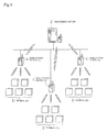
- FIG. 1 is a block diagram illustrating a configuration of the communication system according to the embodiment.
- reference numeral 1 denotes a base station device; 2, a terminal device that performs radio communication to the base station device 1; and 3, a management server 3 that manages a transmission timing of a synchronization signal of the base station device.
- the base station device 1 and the management server 3 are communicably connected to each other.
- three base station devices 1, that is, base station devices 1 a to 1 c are communicably connected to the management server 3, and synchronization signals transmitted from the base station devices 1 a to 1 c are respectively transmitted to terminal device groups 2a to 2c accommodated by the respective base station devices 1.
- the base station devices are distanced from each other by such a distance that a synchronization signal from a base station device 1 can be received by another base station device 1 than the base station device 1 that has transmitted the synchronization signal.
- FIG. 2 is a general timing chart of transmission signals transmitted from the base station devices 1 to the terminal devices 2 according to the present invention.
- the transmission signal includes a synchronization signal S for achieving synchronization between each base station device 1 and each terminal device 2, and communication data D in which real data is transmitted.
- a basic frame transmission period h includes a synchronization period i, in which the synchronization signal S is transmitted, and a data period j, in which the communication data D is transmitted.
- the base station device 1a transmits a synchronization signal Sa at a synchronization signal transmission timing Sti1, which is the first in transmission order in the synchronization period i. Further, the base station device 1b transmits a synchronization signal Sb at a synchronization signal transmission timing Sti2, which is the second in transmission order in the synchronization period i, and the base station device 1c transmits a synchronization signal Sc at a synchronization signal transmission timing Sti3, which is the third in transmission order in the synchronization period i. Further, after the transmission of the synchronization signal S, each of the base station devices 1a to 1c transmits the communication data D in the data period j.
- the base station devices 1 transmit respective pieces of the communication data D one after another so that transmission periods of the pieces of the communication data D of the base station devices do not overlap each other. For example, if a transmission time or a transmission end time of communication data Da is stored in the synchronization signal Sa transmitted from the base station device 1a, whose synchronization signal transmission timing is set as the first, the base station device 1 b, whose synchronization signal transmission timing is the second, refers to the transmission end time of the communication data Da of the base station device 1a to start the transmission of communication data Db thereafter. Further, similarly, the base station device 1c transmits communication data based on the transmission end time of the communication data Db contained in the synchronization signal Sb transmitted by the base station device 1 b.
- FIG. 3 is a functional block diagram of the base station device.
- the base station device 1 includes a radio reception section 11, a control section 12, a clock section 13, a synchronization signal detection section 14, a timing determination section 15, a synchronization signal generation section 16, and a radio transmission section 17.
- the management server 3 provides notification of the transmission order of the synchronization signal to each of the plurality of base station devices 1, and further provides, to each of the plurality of base station devices 1, notification of a base station device 1 that is to serve as a reference station out of the plurality of base station devices 1. Then, if an own device is designated as the base station device that is to serve as the reference station by the management server 3, the base station device 1 performs processing of transmitting the synchronization signal S to the terminal device 2 based on the transmission order.
- the base station device 1 performs processing of transmitting the synchronization signal S to the terminal device 2 at a timing calculated based on a reception timing of a synchronization signal received from the base station device 1 serving as the reference station, the transmission order of that base station device 1 serving as the reference station, and the transmission order of the own device.
- the management server 3 provides, to each of the base station devices 1, notification of the transmission order of the synchronization signal and notification indicating which base station device is to serve as the reference station. Further, the management server 3 provides notification of a start time of the synchronization period i of the basic frame transmission period h.
- the base station device 1 transmits the synchronization signal S to the terminal device 2 in the synchronization period i, and transmits the communication data D, which is to be used for processing, to the terminal device 2 in the data period j. This counting of the basic frame transmission period h is repeated with the base station device 1 and the terminal device 2 in synchronization with each other.
- the synchronization period i is divided to set the timings Sti for transmitting the synchronization signals S, and the base station device 1 transmits the synchronization signal S at a synchronization signal transmission timing Sti corresponding to the transmission order notified by the management server 3 out of the plurality of synchronization signal transmission timings Sti in the synchronization period i. For example, if the transmission order of the base station device 1b is the second, the base station device 1b transmits the synchronization signal Sb at the synchronization signal transmission timing Sti2, which is the second in the synchronization period i.
- the management server 3 transmits, to the base station devices 1 a, 1 b, and 1c, information specifying the transmission orders as the first, the second, and the third, respectively, and also transmits information indicating that the base station device 1 a is the base station device that is to serve as the reference station to each of the base station devices 1a to 1c.
- the radio reception section 11 receives information on the transmission order and information on the base station device 1a serving as the reference station, and the control section 12 records, on a memory or the like, the received information on the transmission order and information indicating whether or not the own device is the base station device serving as the reference station.
- the control section 12 of the base station device 1a serving as the reference station provides notification prompting the timing determination section 15 to determine the transmission timing of the synchronization signal.
- notification has been provided that the base station device 1a is the reference station, and the transmission order thereof is the first. Therefore, the synchronization signal Sa is transmitted at the synchronization signal transmission timing Sti1, which is the first in the synchronization period i, without performing any particular timing correction or the like.
- FIG. 4 is a diagram illustrating an overview of operations of the base station device 1 serving as the reference station and the terminal device 2.
- the terminal device 2 accommodated by the base station device 1 detects, based on the synchronization signal S, the reception timing of the communication data D, which is to be transmitted from the base station device 1 after the transmission of the synchronization signal S, and the reception timing of a synchronization signal S+1, which is to be received next after the reception of the synchronization signal S.
- the synchronization signal S has stored therein information for identifying a time length ta of the basic frame transmission period h and a start time Tc of the communication data D.
- the terminal device 2 receives the synchronization signal S from the base station device 1, reads the time length ta of the basic frame transmission period h, and adds the time length ta of the basic frame transmission period h to a reception time Tb1 of the synchronization signal S, to thereby calculate a time Tb2, at which the next synchronization signal S+1 is to be received. Further, the terminal device 2 receives the synchronization signal S transmitted from the base station device 1, reads the information for identifying the start time Tc of the communication data D, which is stored in the synchronization signal S, and calculates, based on the information, the reception time of the communication data D to be transmitted from the base station device 1 after the reception of the synchronization signal S.
- the terminal device 2 adds the transition time read from the synchronization signal to the reception time of the synchronization signal, and thus can calculate the reception time of the communication data. Note that, this processing of the terminal device 2 is equally performed by both a terminal device accommodated by the base station device serving as the reference station and a terminal device accommodated by the base station device not serving as the reference station.
- the terminal device 2 calculates the start time Tc of the communication data D to be transmitted from the base station device 1 after the reception of the synchronization signal S, and the reception time Tb2 of the next synchronization signal S+1, thereby being activated to operate only in time periods in which the synchronization signal S and the communication data D are received (operation periods tf), and entering into a sleep state in the other time periods than the operation periods tf (quiescent periods tg).
- operation periods tf time periods in which the synchronization signal S and the communication data D are received
- quiescent periods tg quiescent periods
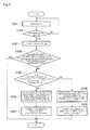
- FIG. 5 is a first diagram illustrating a flow of synchronization signal transmission processing performed by the base station device not serving as the reference station.
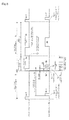
- FIG. 6 is a first diagram illustrating a processing overview of the synchronization signal transmission processing.
- the base station device 1 a is herein set as the reference station, whereas the base station devices 1b and 1 c are set as the base station devices not serving as the reference station.
- each of the control sections 12 of the base station devices 1b and 1 c not serving as the reference station receives the synchronization signal transmitted from the base station device 1a serving as the reference station, and determines, based on the synchronization signal, the transmission timing of the synchronization signal of the own device.
- the base station devices 1b and 1 c both perform the same operation, and hence description of the base station device 1c is herein omitted.
- Step S101 when the base station device 1 b not serving as the reference station receives data (Step S101), the synchronization signal detection section 14 determines whether or not the received data is the synchronization signal (Step S102). When it is determined in Step S102 that the synchronization signal has been received, the synchronization signal detection section 14 of the base station device 1 b not serving as the reference station subsequently provides notification of the reception time to the timing determination section 15. Then, the timing determination section 15 records the reception time on a memory or the like (Step S103).
- the synchronization signal transmission timing Sti2 of the base station device 1 b whose synchronization signal transmission timing Sti is the second, is 1 msec after the rising edge of the synchronization signal Sa transmitted from the base station device 1a serving as the reference station in the synchronization period i.
- This timing is an expected transmission time Tp of an original synchronization signal Sb' of the base station device 1b, which is calculated based on a reception time To of the synchronization signal Sa of the base station device 1 a.
- the timing determination section 15 of the base station device 1b not serving as the reference station makes a comparison between a transmission time Tq of the next synchronization signal Sb, that is, a transmission time Tq of the next synchronization signal Sb obtained based on the counting of its own, and the expected transmission time Tp of the synchronization signal Sb' of the base station device 1b (Steps S104 and S105).
- the transmission time Tq is obtained by adding a basic frame transmission period length tk to a transmission time Tq-1 of a previous synchronization signal Sb-1 (or a time corresponding to the synchronization signal transmission timing Sti2 of the base station device 1b from the start time of the synchronization period i of the basic frame transmission period h, which is notified by the management server 3).
- the expected transmission time Tp is calculated based on the reception time To of the synchronization signal Sa received from the base station device 1a serving as the reference station and the synchronization signal transmission timing Sti2 of the base station device 1 b.
- the base station device 1b uses the synchronization signal Sb to transmit notification indicating that the transmission timing of a next synchronization signal Sb+1 is to be corrected by ⁇ t to the terminal device 2b to which the base station device 1b transmits the synchronization signal (Step S106).
- the base station device 1b corrects the transmission time of the synchronization signal Sb+1, which is next to the synchronization signal Sb to be transmitted from the base station device 1 b immediately after the synchronization signal Sa is received from the base station device 1a, into a transmission time Tq+1 of the synchronization signal Sb+1 of the base station device 1 b, which is calculated based on the reception time To of the synchronization signal Sa received from the base station device 1a serving as the reference station and the synchronization signal transmission timing Sti2 of the base station device 1b (Step S107).
- the synchronization signal Sb which is transmitted by the own device immediately after the reception of the synchronization signal received from the base station device 1a serving as the reference station, is transmitted based on the counting of the own device without any particular correction.
- a determination that there is a time lag between the transmission time Tq' and the expected transmission time Tp is made after the base station device 1 b has already provided notification of a transmission (reception) time Tq+1' of the next synchronization signal Sb+1 to the terminal device 2b to which the base station device 1 b transmits the synchronization signal.
- the base station device 1 b does not correct the transmission timing of the next synchronization signal Sb+1, and, instead, uses the synchronization signal Sb+1 to transmit notification indicating that the transmission timing of a synchronization signal Sb+2 after next is to be corrected by ⁇ t to the terminal device 2b to which the base station device 1b transmits the synchronization signal (Step S108). Then, the transmission time of the synchronization signal Sb+2 after next of the base station device 1 b is corrected to Tq+2' (Step S109).
- the base station device 1 a which transmits the synchronization signal Sa at the earliest synchronization signal transmission timing Sti, is set as the reference station, but a base station device whose synchronization signal transmission timing Sti is later than that of another base station device may be set as the reference station.
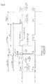
- FIG. 8 is a third diagram illustrating a processing overview of correction processing for the synchronization signal.
- each of the base station devices 1 a to 1c has already received from the management server 3 notification indicating that the base station device 1 b is the reference station.
- the timing determination section 15 of the base station device 1a detects that the own device is no longer the reference station, terminates the operation as the reference station, and starts, based on the synchronization signal transmitted from the new reference station, processing of achieving synchronization of the start time of the basic frame transmission period and timings of the synchronization period and the data period.
- the timing determination section 15 of the base station device 1b stops the processing of achieving, based on the synchronization signal of another base station device 1 a or 1 c, synchronization of the start time of the basic frame transmission period and the timings of the synchronization period and the data period. Then, the synchronization signal generation section 16 of the base station device 1c transmits the synchronization signal at the synchronization signal transmission timing (transmission order: third) in the synchronization period of the basic frame transmission period, which has been used until that time point.
- Step S101 when the base station device 1a not serving as the reference station receives data (Step S101), the synchronization signal detection section 14 determines whether or not the received data is the synchronization signal (Step S102). When it is determined in Step S102 that the synchronization signal has been received, the synchronization signal detection section 14 of the base station device 1a not serving as the reference station subsequently provides notification of the reception time to the timing determination section 15. Then, the timing determination section 15 records the reception time on a memory or the like (Step S103).
- the timing determination section 15 of the base station device 1a not serving as the reference station makes a comparison between a transmission time Tq of the next synchronization signal, that is, a transmission time Tq of the next synchronization signal obtained based on the counting of its own, and an expected transmission time Tp of the next synchronization signal of the own device (Step S104).
- the transmission time Tq is obtained by adding the basic frame transmission period length tk to a transmission time Tq-1 of a previous synchronization signal Sa-1.
- the expected transmission time Tp is calculated based on the reception time To of the synchronization signal Sb received from the base station device 1b serving as the reference station and the transmission order of the own device.
- the transmission time Tp of a next expected synchronization signal Sa' of the base station device 1a which can be calculated based on the synchronization signal Sb received from the base station device 1b serving as the reference station, can be determined through calculation as a time obtained by subtracting 1 msec, which corresponds to one synchronization signal, from the reception time To of the synchronization signal Sb transmitted from the base station device 1 b serving as the reference station.
- Step S104 a comparison is made between the transmission time Tq of the next synchronization signal Sa, that is, the transmission time Tq of the next synchronization signal Sa obtained based on the counting of its own, and the expected transmission time Tp of the synchronization signal Sa' of the own device.
- the transmission time Tq is obtained by adding the basic frame transmission period length tk to the transmission time Tq-1 of the previous synchronization signal Sa-1.
- the expected transmission time Tp can be calculated based on the reception time To of the synchronization signal Sb received from the base station device 1b serving as the reference station and the synchronization signal transmission timing Sti1 of the own device.
- a time lag ( ⁇ t) between the reception time To and the expected transmission time Tp it is determined whether or not the synchronization signal Sa of the base station device 1 a has already been transmitted.
- the transmission time Tq of the synchronization signal Sa of the base station device 1 a is earlier than the reception time To as in FIG. 8 , that is, a case where the synchronization signal Sa has already been transmitted
- a determination that there is a time lag between the transmission time Tq and the expected transmission time Tp is made after the base station device 1a has already provided notification of a transmission (reception) time Tq+1 of a next synchronization signal Sa+1 to the terminal device 2a to which the base station device 1a transmits the synchronization signal.
- the base station device 1a does not correct the transmission timing of the next synchronization signal Sa+1, and, instead, uses the synchronization signal Sa+1 to transmit notification indicating that the transmission timing of a synchronization signal Sa+2 after next is to be corrected by ⁇ t to the terminal device 2a to which the base station device 1a transmits the synchronization signal (Step 108). Then, the transmission time of the synchronization signal Sa+2 after next of the base station device 1 a is corrected to Tq+2 (Step 109).
- the base station device 1a uses the synchronization signal Sa to transmit notification indicating that the transmission timing of the next synchronization signal Sa+1 is to be corrected by ⁇ t to the terminal device 2a to which the base station device 1 a transmits the synchronization signal (Step S106).
- the base station device 1a corrects the transmission time of the synchronization signal Sa+1, which is next to the synchronization signal Sa to be transmitted from the base station device 1a immediately after the synchronization signal Sb is received from the base station device 1 b, into the transmission time Tq+1 of the synchronization signal Sa+1 of the base station device 1 a, which is calculated based on the reception time To of the synchronization signal Sb received from the base station device 1b serving as the reference station and the synchronization signal transmission timing Sti1 of the base station device 1a (Step S107).
- the transmission may be performed at a different radio frequency for the data period j in which the communication data D is transmitted, and, only for the synchronization period i in which the synchronization signal S is transmitted, the transmission may be performed at the same frequency through time division.
- the synchronization signals S are transmitted from the base station devices 1 in synchronization through the same processing as the processing illustrated in FIG. 4 and FIG. 6 .
- the synchronization signal transmitted from each base station device may be provided with a guard time.
- FIG. 10 is a diagram illustrating an overview of guard time insertion processing.
- the base station device 1 whose transmission order is not the first may count a guard time c between a time at which the synchronization signal is transmitted from a base station device 1 that comes immediately before in transmission order and a time at which the synchronization signal is transmitted from the own device, and transmit the synchronization signal after the counting of the guard time c is finished.
- each of the base station devices 1 transmits the synchronization signal once in the synchronization period, but may continuously transmit a plurality of identical synchronization signals in the synchronization signal transmission period of the own device.
- FIG. 11 is a diagram illustrating an overview of another transmission method for the synchronization signal.
- FIG. 11 illustrates an example in which the base station devices 1 a, 1 b, and 1 c continuously transmit identical synchronization signals Sa, Sb, and Sc sixteen times in single synchronization signal transmission periods STa, STb, and STc, respectively.
- a transmission interval between the synchronization signals S in the synchronization signal transmission period ST is 1 msec.
- the terminal device 2 normally performs processing of: in order to receive the synchronization signal S from the base station device 1, being activated from the sleep state before the synchronization signal S is transmitted to wait for the synchronization signal S to be transmitted; after the reception of the synchronization signal S, transitioning to the sleep state again until a timing at which the next communication data is transmitted comes; and predicting a time at which the communication data D is to be transmitted to be activated from the sleep state again.
- a time period used for waiting for the synchronization signal S to be transmitted be reduced as much as possible.
- the base station devices 1 transmit the identical synchronization signals S a plurality of times in the respective synchronization signal transmission periods ST.
- the terminal device 2 only needs to receive any one of the plurality of synchronization signals S.
- the terminal device 2 transitions to the sleep state immediately. In this manner, even if the clock section serving as a reference for the synchronization signal of the terminal device 2 is not of high precision, it is possible to reduce the power consumption by reducing the time period used for waiting for the synchronization signal S to be received.
- the plurality of synchronization signals S in the synchronization signal transmission period ST have stored therein sequence numbers (in the case of FIG. 11 , numbers from 0 to 15), and hence, based on a sequence number contained in the synchronization signal S received first after the activation from the sleep state, the terminal device 2 corrects a predicted timing for the reception of the synchronization signal transmitted from the base station device.
- the predicted timing is set as a timing of Sa7, which is at the center of the synchronization signal transmission period ST
- a synchronization signal Sa4 having a sequence number 3 assigned thereto is the first signal received after the terminal device 2 was activated from the sleep state
- the terminal device 2 which has made such a determination as described above, performs correction so that the activation time from the sleep state for reception of the next synchronization signal S is delayed by 3 msec.
- the management server provides, to the base station devices, notification of the transmission order of the synchronization signal and of the base station device that is to serve as the reference station. Based on the synchronization signal transmitted from the base station device designated as the reference station through the notification, each of the base station devices not serving as the reference station determines the timing of the synchronization signal by the own device and transmits the synchronization signal.
- the management server does not need to perform processing of calculating when the synchronization signal is to be transmitted from each of the base station devices, and hence it is possible to reduce a processing load imposed on the management server.
- the base station device serving as the reference station only needs to transmit the synchronization signal at the synchronization signal transmission timing corresponding to the transmission order in the synchronization period after the reception of the notification of the transmission order from the management server.
- the base station device serving as the reference station does not need to perform processing of calculating when to transmit the synchronization signal, and hence it is possible to reduce the processing load imposed thereon.
- the above-mentioned devices and server each include a computer system. Then, each of the procedures of the processing described above is stored in a computer-readable recording medium in a form of program, and the above-mentioned processing is performed by a computer reading and executing the program.
- the computer-readable recording medium refers to a magnetic disk, a magneto-optical disk, a CD-ROM, a DVD-ROM, a semiconductor memory, and the like.
- the computer program may be distributed to the computer via a communication line so that the computer that receives the distribution executes the program.
- the above-mentioned program may be a program that implements part of the above-mentioned function. Further, the above-mentioned program may be a program that implements the above-mentioned function in combination with a program that is already recorded in the computer system, that is, a so-called differential file (differential program).
Landscapes
- Engineering & Computer Science (AREA)
- Computer Networks & Wireless Communication (AREA)
- Signal Processing (AREA)
- Mobile Radio Communication Systems (AREA)
- Synchronisation In Digital Transmission Systems (AREA)
Description
- The present invention relates to a communication system and a communication method for controlling a timing at which a base station device transmits a synchronization signal to a terminal device.
- Conventionally, a synchronization signal is transmitted/received between a terminal device and a base station device which are communicably connected to each other by radio, and, by using the synchronization signal, synchronization of a signal is achieved between the terminal device and the base station device. Further, the synchronization signal is also used when a plurality of base station devices are controlled so as not to transmit data at the same timing thereamong to terminal devices accommodated by the respective own devices.
Patent Literature 1 discloses a technology of performing control so as not to transmit a synchronization signal at the same time as when another base station device transmits a synchronization signal. Further,Patent Literature 2 discloses a technology of setting information in a base station device in advance so that base station devices do not transmit synchronization signals at the same time. -
- Patent Literature 1:
JP 2993469 B2 - Patent Literature 2:
JP 3749907 B2 -
FR 2 784 257 -
EP 1 903 690 - Here, a synchronization signal, which is to be transmitted from a base station device to a terminal device, needs to be controlled so as not to collide with a synchronization signal to be transmitted from another base station device. At the same time, it is desired to, by making such processing as simple as possible, reduce processing loads imposed on the base station device and a server that sets a timing of the synchronization signal for the base station device.
- In view of the above, it is an object of the present invention to provide a communication system and a communication method which are capable of reducing processing loads imposed on a base station device and a server that sets a timing of a synchronization signal for the base station device.
- In order to achieve the above-mentioned object, according to the present invention, there is provided a communication system as defined in
claim 1. - Further, according to the present invention, there is provided a communication method as defined in claim 5.
- According to the present invention, a management server provides, to the base station device, notification of the transmission order of the synchronization signal and of the base station device that is to serve as a reference station. Based on the synchronization signal transmitted from the base station device designated as the reference station through the notification, each of the base station devices not serving as the reference station determines the timing of the synchronization signal by the own device and transmits the synchronization signal. With this configuration, the management server does not need to perform processing of calculating when the synchronization signal is to be transmitted from each of the base station devices, and hence it is possible to reduce the processing load imposed on the management server. Further, the base station device serving as the reference station only needs to transmit the synchronization signal at a synchronization signal transmission timing corresponding to the transmission order in a synchronization period after reception of the notification of the transmission order from the management server. As a result, the base station device serving as the reference station does not need to perform processing of calculating when to transmit the synchronization signal, and hence it is possible to reduce the processing load imposed thereon.
-
- [
FIG. 1 ] A block diagram illustrating a configuration of a communication system. - [
FIG. 2 ] A diagram illustrating an overview of operations of base station devices. - [
FIG. 3 ] A functional block diagram of the base station device. - [
FIG. 4 ] A diagram illustrating an overview of operations of the base station device serving as a reference station and a terminal device. - [
FIG. 5 ] A first diagram illustrating a flow of synchronization signal transmission processing performed by the base station device not serving as the reference station. - [
FIG. 6 ] A first diagram illustrating a processing overview of the synchronization signal transmission processing. - [
FIG. 7 ] A second diagram illustrating a processing overview of correction processing for the synchronization signal. - [
FIG. 8 ] A third diagram illustrating a processing overview of the correction processing for the synchronization signal. - [
FIG. 9 ] A second diagram illustrating a processing overview of the synchronization signal transmission processing. - [
FIG. 10 ] A diagram illustrating an overview of guard time insertion processing. - [
FIG. 11 ] A diagram illustrating an overview of another transmission method for the synchronization signal. - Hereinbelow, description is given of a communication system according to an embodiment of the present invention with reference to the drawings.
-
FIG. 1 is a block diagram illustrating a configuration of the communication system according to the embodiment. - In
FIG. 1 ,reference numeral 1 denotes a base station device; 2, a terminal device that performs radio communication to thebase station device 1; and 3, amanagement server 3 that manages a transmission timing of a synchronization signal of the base station device. Thebase station device 1 and themanagement server 3 are communicably connected to each other. In this figure, threebase station devices 1, that is,base station devices 1 a to 1 c, are communicably connected to themanagement server 3, and synchronization signals transmitted from thebase station devices 1 a to 1 c are respectively transmitted toterminal device groups 2a to 2c accommodated by the respectivebase station devices 1. The base station devices are distanced from each other by such a distance that a synchronization signal from abase station device 1 can be received by anotherbase station device 1 than thebase station device 1 that has transmitted the synchronization signal. -
FIG. 2 is a general timing chart of transmission signals transmitted from thebase station devices 1 to theterminal devices 2 according to the present invention. - The transmission signal includes a synchronization signal S for achieving synchronization between each
base station device 1 and eachterminal device 2, and communication data D in which real data is transmitted. A basic frame transmission period h includes a synchronization period i, in which the synchronization signal S is transmitted, and a data period j, in which the communication data D is transmitted. - Then, as illustrated in
FIG. 2 , thebase station device 1a transmits a synchronization signal Sa at a synchronization signal transmission timing Sti1, which is the first in transmission order in the synchronization period i. Further, thebase station device 1b transmits a synchronization signal Sb at a synchronization signal transmission timing Sti2, which is the second in transmission order in the synchronization period i, and the base station device 1c transmits a synchronization signal Sc at a synchronization signal transmission timing Sti3, which is the third in transmission order in the synchronization period i. Further, after the transmission of the synchronization signal S, each of thebase station devices 1a to 1c transmits the communication data D in the data period j. Here, in a case where the transmission signals have the same frequency (time division) as illustrated inFIG. 2 , thebase station devices 1 transmit respective pieces of the communication data D one after another so that transmission periods of the pieces of the communication data D of the base station devices do not overlap each other. For example, if a transmission time or a transmission end time of communication data Da is stored in the synchronization signal Sa transmitted from thebase station device 1a, whose synchronization signal transmission timing is set as the first, thebase station device 1 b, whose synchronization signal transmission timing is the second, refers to the transmission end time of the communication data Da of thebase station device 1a to start the transmission of communication data Db thereafter. Further, similarly, the base station device 1c transmits communication data based on the transmission end time of the communication data Db contained in the synchronization signal Sb transmitted by thebase station device 1 b. -
FIG. 3 is a functional block diagram of the base station device. - As illustrated in
FIG. 3 , thebase station device 1 includes a radio reception section 11, acontrol section 12, aclock section 13, a synchronizationsignal detection section 14, atiming determination section 15, a synchronizationsignal generation section 16, and aradio transmission section 17. - Then, in the communication system according to this embodiment, the
management server 3 provides notification of the transmission order of the synchronization signal to each of the plurality ofbase station devices 1, and further provides, to each of the plurality ofbase station devices 1, notification of abase station device 1 that is to serve as a reference station out of the plurality ofbase station devices 1. Then, if an own device is designated as the base station device that is to serve as the reference station by themanagement server 3, thebase station device 1 performs processing of transmitting the synchronization signal S to theterminal device 2 based on the transmission order. If the own device is not designated as the base station device that is to serve as the reference station by themanagement server 3, thebase station device 1 performs processing of transmitting the synchronization signal S to theterminal device 2 at a timing calculated based on a reception timing of a synchronization signal received from thebase station device 1 serving as the reference station, the transmission order of thatbase station device 1 serving as the reference station, and the transmission order of the own device. - Next, detailed description is given of processing performed by each of the management server, the base station device, and the terminal device in the communication system.
- First, the
management server 3 provides, to each of thebase station devices 1, notification of the transmission order of the synchronization signal and notification indicating which base station device is to serve as the reference station. Further, themanagement server 3 provides notification of a start time of the synchronization period i of the basic frame transmission period h. Here, as illustrated inFIG. 2 , thebase station device 1 transmits the synchronization signal S to theterminal device 2 in the synchronization period i, and transmits the communication data D, which is to be used for processing, to theterminal device 2 in the data period j. This counting of the basic frame transmission period h is repeated with thebase station device 1 and theterminal device 2 in synchronization with each other. Further, the synchronization period i is divided to set the timings Sti for transmitting the synchronization signals S, and thebase station device 1 transmits the synchronization signal S at a synchronization signal transmission timing Sti corresponding to the transmission order notified by themanagement server 3 out of the plurality of synchronization signal transmission timings Sti in the synchronization period i. For example, if the transmission order of thebase station device 1b is the second, thebase station device 1b transmits the synchronization signal Sb at the synchronization signal transmission timing Sti2, which is the second in the synchronization period i. - Then, in this embodiment, as illustrated in
FIG. 1 , threebase station devices 1, that is, thebase station devices management server 3. Here, themanagement server 3 transmits, to thebase station devices base station device 1 a is the base station device that is to serve as the reference station to each of thebase station devices 1a to 1c. In thebase station devices 1a to 1c, the radio reception section 11 receives information on the transmission order and information on thebase station device 1a serving as the reference station, and thecontrol section 12 records, on a memory or the like, the received information on the transmission order and information indicating whether or not the own device is the base station device serving as the reference station. - The
control section 12 of thebase station device 1a serving as the reference station provides notification prompting thetiming determination section 15 to determine the transmission timing of the synchronization signal. Next, thetiming determination section 15, which receives clock signals from theclock section 13, transmits the synchronization signal S at the synchronization signal transmission timing Sti corresponding to the transmission order, which has been notified to the own device, in the synchronization period i of the basic frame transmission period h. Specifically, in this situation, notification has been provided that thebase station device 1a is the reference station, and the transmission order thereof is the first. Therefore, the synchronization signal Sa is transmitted at the synchronization signal transmission timing Sti1, which is the first in the synchronization period i, without performing any particular timing correction or the like. -
FIG. 4 is a diagram illustrating an overview of operations of thebase station device 1 serving as the reference station and theterminal device 2. - As illustrated in the figure, when the
base station device 1 transmits the synchronization signal S, theterminal device 2 accommodated by thebase station device 1 detects, based on the synchronization signal S, the reception timing of the communication data D, which is to be transmitted from thebase station device 1 after the transmission of the synchronization signal S, and the reception timing of a synchronization signal S+1, which is to be received next after the reception of the synchronization signal S. Specifically, the synchronization signal S has stored therein information for identifying a time length ta of the basic frame transmission period h and a start time Tc of the communication data D. - Then, the
terminal device 2 receives the synchronization signal S from thebase station device 1, reads the time length ta of the basic frame transmission period h, and adds the time length ta of the basic frame transmission period h to a reception time Tb1 of the synchronization signal S, to thereby calculate a time Tb2, at which the next synchronization signal S+1 is to be received. Further, theterminal device 2 receives the synchronization signal S transmitted from thebase station device 1, reads the information for identifying the start time Tc of the communication data D, which is stored in the synchronization signal S, and calculates, based on the information, the reception time of the communication data D to be transmitted from thebase station device 1 after the reception of the synchronization signal S. For example, if the information for identifying the start time Tc of the communication data D, which is stored in the synchronization signal S, indicates a transition time td since the transmission (reception) time Tb1 of the synchronization signal S of thebase station device 1, theterminal device 2 adds the transition time read from the synchronization signal to the reception time of the synchronization signal, and thus can calculate the reception time of the communication data. Note that, this processing of theterminal device 2 is equally performed by both a terminal device accommodated by the base station device serving as the reference station and a terminal device accommodated by the base station device not serving as the reference station. - Then, the
terminal device 2 calculates the start time Tc of the communication data D to be transmitted from thebase station device 1 after the reception of the synchronization signal S, and the reception time Tb2 of the next synchronization signal S+1, thereby being activated to operate only in time periods in which the synchronization signal S and the communication data D are received (operation periods tf), and entering into a sleep state in the other time periods than the operation periods tf (quiescent periods tg). As a result, it is possible to reduce the power consumption of theterminal device 2. Owing to this, in a case where an internal battery is used, a long-time operation of theterminal device 2 can be achieved. -
FIG. 5 is a first diagram illustrating a flow of synchronization signal transmission processing performed by the base station device not serving as the reference station. -
FIG. 6 is a first diagram illustrating a processing overview of the synchronization signal transmission processing. - The
base station device 1 a is herein set as the reference station, whereas thebase station devices 1b and 1 c are set as the base station devices not serving as the reference station. - Next, referring to
FIG. 5 andFIG. 6 , description is given of processing in which each of thecontrol sections 12 of thebase station devices 1b and 1 c not serving as the reference station receives the synchronization signal transmitted from thebase station device 1a serving as the reference station, and determines, based on the synchronization signal, the transmission timing of the synchronization signal of the own device. Note that, thebase station devices 1b and 1 c both perform the same operation, and hence description of the base station device 1c is herein omitted. - First, when the
base station device 1 b not serving as the reference station receives data (Step S101), the synchronizationsignal detection section 14 determines whether or not the received data is the synchronization signal (Step S102). When it is determined in Step S102 that the synchronization signal has been received, the synchronizationsignal detection section 14 of thebase station device 1 b not serving as the reference station subsequently provides notification of the reception time to thetiming determination section 15. Then, thetiming determination section 15 records the reception time on a memory or the like (Step S103). Here, assuming that a time period from the rising edge of the synchronization signal to the falling edge thereof is 1 msec, the synchronization signal transmission timing Sti2 of thebase station device 1 b, whose synchronization signal transmission timing Sti is the second, is 1 msec after the rising edge of the synchronization signal Sa transmitted from thebase station device 1a serving as the reference station in the synchronization period i. This timing is an expected transmission time Tp of an original synchronization signal Sb' of thebase station device 1b, which is calculated based on a reception time To of the synchronization signal Sa of thebase station device 1 a. - Next, the
timing determination section 15 of thebase station device 1b not serving as the reference station makes a comparison between a transmission time Tq of the next synchronization signal Sb, that is, a transmission time Tq of the next synchronization signal Sb obtained based on the counting of its own, and the expected transmission time Tp of the synchronization signal Sb' of thebase station device 1b (Steps S104 and S105). The transmission time Tq is obtained by adding a basic frame transmission period length tk to a transmission time Tq-1 of a previous synchronization signal Sb-1 (or a time corresponding to the synchronization signal transmission timing Sti2 of thebase station device 1b from the start time of the synchronization period i of the basic frame transmission period h, which is notified by the management server 3). The expected transmission time Tp is calculated based on the reception time To of the synchronization signal Sa received from thebase station device 1a serving as the reference station and the synchronization signal transmission timing Sti2 of thebase station device 1 b. - In a case where the synchronization signal Sb has not been transmitted yet, that is, a case where the transmission time Tq is later than the expected transmission time Tp, the
base station device 1b uses the synchronization signal Sb to transmit notification indicating that the transmission timing of a next synchronization signal Sb+1 is to be corrected by Δt to theterminal device 2b to which thebase station device 1b transmits the synchronization signal (Step S106). Then, thebase station device 1b corrects the transmission time of the synchronization signal Sb+1, which is next to the synchronization signal Sb to be transmitted from thebase station device 1 b immediately after the synchronization signal Sa is received from thebase station device 1a, into a transmissiontime Tq+ 1 of the synchronization signal Sb+1 of thebase station device 1 b, which is calculated based on the reception time To of the synchronization signal Sa received from thebase station device 1a serving as the reference station and the synchronization signal transmission timing Sti2 of thebase station device 1b (Step S107). Note that, the synchronization signal Sb, which is transmitted by the own device immediately after the reception of the synchronization signal received from thebase station device 1a serving as the reference station, is transmitted based on the counting of the own device without any particular correction. - Referring to
FIG. 7 , description is given of correction performed in a case where the synchronization signal Sb has already been transmitted on the other hand, that is, a case where a transmission time Tq' is earlier than the expected transmission time Tp. - As illustrated in
FIG. 7 , in the case where a transmission time Tq' of the synchronization signal Sb of thebase station device 1b is earlier than the expected transmission time Tp, a determination that there is a time lag between the transmission time Tq' and the expected transmission time Tp is made after thebase station device 1 b has already provided notification of a transmission (reception) time Tq+1' of the next synchronization signal Sb+1 to theterminal device 2b to which thebase station device 1 b transmits the synchronization signal. Accordingly, thebase station device 1 b does not correct the transmission timing of the next synchronization signal Sb+1, and, instead, uses the synchronization signal Sb+1 to transmit notification indicating that the transmission timing of a synchronization signal Sb+2 after next is to be corrected by Δt to theterminal device 2b to which thebase station device 1b transmits the synchronization signal (Step S108). Then, the transmission time of the synchronization signal Sb+2 after next of thebase station device 1 b is corrected to Tq+2' (Step S109). - In the processing described above, the
base station device 1 a, which transmits the synchronization signal Sa at the earliest synchronization signal transmission timing Sti, is set as the reference station, but a base station device whose synchronization signal transmission timing Sti is later than that of another base station device may be set as the reference station. -
FIG. 8 is a third diagram illustrating a processing overview of correction processing for the synchronization signal. - Next, description is given of an example in which the transmission order of the base station device serving as the reference station is not the first.
- First, it is assumed that each of the
base station devices 1 a to 1c has already received from themanagement server 3 notification indicating that thebase station device 1 b is the reference station. In response thereto, in a case where thebase station device 1a was originally set as the reference station, thetiming determination section 15 of thebase station device 1a detects that the own device is no longer the reference station, terminates the operation as the reference station, and starts, based on the synchronization signal transmitted from the new reference station, processing of achieving synchronization of the start time of the basic frame transmission period and timings of the synchronization period and the data period. Further, in response to the reception of the notification indicating that thebase station device 1 b is to be set as the reference station, thetiming determination section 15 of thebase station device 1b stops the processing of achieving, based on the synchronization signal of anotherbase station device 1 a or 1 c, synchronization of the start time of the basic frame transmission period and the timings of the synchronization period and the data period. Then, the synchronizationsignal generation section 16 of the base station device 1c transmits the synchronization signal at the synchronization signal transmission timing (transmission order: third) in the synchronization period of the basic frame transmission period, which has been used until that time point. - Next, description is given of processing in which the
control section 12 of each of thebase station devices 1a and 1c not serving as the reference station receives the synchronization signal transmitted from thebase station device 1b serving as the reference station, and determines, based on the synchronization signal, the transmission timing of the synchronization signal of the own device. Note that, the operation of the base station device 1c is the same as the operation of thebase station device 1b which is performed in the above-mentioned case where thebase station device 1a is set as the reference station, and hence description thereof is omitted herein. Further, the processing overview of the synchronization correction is the same as inFIG. 4 , and hence the processing procedures are described with reference toFIG. 4 . - First, when the
base station device 1a not serving as the reference station receives data (Step S101), the synchronizationsignal detection section 14 determines whether or not the received data is the synchronization signal (Step S102). When it is determined in Step S102 that the synchronization signal has been received, the synchronizationsignal detection section 14 of thebase station device 1a not serving as the reference station subsequently provides notification of the reception time to thetiming determination section 15. Then, thetiming determination section 15 records the reception time on a memory or the like (Step S103). - Next, the
timing determination section 15 of thebase station device 1a not serving as the reference station makes a comparison between a transmission time Tq of the next synchronization signal, that is, a transmission time Tq of the next synchronization signal obtained based on the counting of its own, and an expected transmission time Tp of the next synchronization signal of the own device (Step S104). The transmission time Tq is obtained by adding the basic frame transmission period length tk to a transmission time Tq-1 of a previous synchronization signal Sa-1. The expected transmission time Tp is calculated based on the reception time To of the synchronization signal Sb received from thebase station device 1b serving as the reference station and the transmission order of the own device. Here, for example, considering that the transmission order of thebase station device 1b serving as the reference station is the second, and that the synchronization signal transmission timing Sti1 of thebase station device 1a not serving as the reference station is the first, the transmission time Tp of a next expected synchronization signal Sa' of thebase station device 1a, which can be calculated based on the synchronization signal Sb received from thebase station device 1b serving as the reference station, can be determined through calculation as a time obtained by subtracting 1 msec, which corresponds to one synchronization signal, from the reception time To of the synchronization signal Sb transmitted from thebase station device 1 b serving as the reference station. - Then, a comparison is made between the transmission time Tq of the next synchronization signal Sa, that is, the transmission time Tq of the next synchronization signal Sa obtained based on the counting of its own, and the expected transmission time Tp of the synchronization signal Sa' of the own device (Step S104). The transmission time Tq is obtained by adding the basic frame transmission period length tk to the transmission time Tq-1 of the previous synchronization signal Sa-1. The expected transmission time Tp can be calculated based on the reception time To of the synchronization signal Sb received from the
base station device 1b serving as the reference station and the synchronization signal transmission timing Sti1 of the own device. In a case where there is a time lag (Δt) between the reception time To and the expected transmission time Tp, it is determined whether or not the synchronization signal Sa of thebase station device 1 a has already been transmitted. In a case where the transmission time Tq of the synchronization signal Sa of thebase station device 1 a is earlier than the reception time To as inFIG. 8 , that is, a case where the synchronization signal Sa has already been transmitted, a determination that there is a time lag between the transmission time Tq and the expected transmission time Tp is made after thebase station device 1a has already provided notification of a transmission (reception)time Tq+ 1 of a next synchronization signal Sa+1 to theterminal device 2a to which thebase station device 1a transmits the synchronization signal. Accordingly, thebase station device 1a does not correct the transmission timing of the next synchronization signal Sa+1, and, instead, uses the synchronization signal Sa+1 to transmit notification indicating that the transmission timing of a synchronization signal Sa+2 after next is to be corrected by Δt to theterminal device 2a to which thebase station device 1a transmits the synchronization signal (Step 108). Then, the transmission time of the synchronization signal Sa+2 after next of thebase station device 1 a is corrected to Tq+2 (Step 109). - In a case where the transmission time Tq of the synchronization signal Sa of the
base station device 1 a is later than the reception time To, that is, a case where the synchronization signal Sa has not been transmitted yet, though not illustrated inFIG. 6 , thebase station device 1a uses the synchronization signal Sa to transmit notification indicating that the transmission timing of the next synchronization signal Sa+1 is to be corrected by Δt to theterminal device 2a to which thebase station device 1 a transmits the synchronization signal (Step S106). Then, thebase station device 1a corrects the transmission time of the synchronization signal Sa+1, which is next to the synchronization signal Sa to be transmitted from thebase station device 1a immediately after the synchronization signal Sb is received from thebase station device 1 b, into the transmissiontime Tq+ 1 of the synchronization signal Sa+1 of thebase station device 1 a, which is calculated based on the reception time To of the synchronization signal Sb received from thebase station device 1b serving as the reference station and the synchronization signal transmission timing Sti1 of thebase station device 1a (Step S107). - In the description of the present invention, there has been given an example in which all the signals transmitted from the respective base station devices have the same radio frequency. However, as illustrated in
FIG. 9 , the transmission may be performed at a different radio frequency for the data period j in which the communication data D is transmitted, and, only for the synchronization period i in which the synchronization signal S is transmitted, the transmission may be performed at the same frequency through time division. In this case, only the synchronization signals S are transmitted from thebase station devices 1 in synchronization through the same processing as the processing illustrated inFIG. 4 andFIG. 6 . - Further, in order to avoid contention with another base station device, the synchronization signal transmitted from each base station device may be provided with a guard time.
-
FIG. 10 is a diagram illustrating an overview of guard time insertion processing. - As illustrated in
FIG. 10 , in order to prevent the transmission periods of the synchronization signals from overlapping each other due to a clock error or a transmission delay, thebase station device 1 whose transmission order is not the first may count a guard time c between a time at which the synchronization signal is transmitted from abase station device 1 that comes immediately before in transmission order and a time at which the synchronization signal is transmitted from the own device, and transmit the synchronization signal after the counting of the guard time c is finished. - In the processing described above, each of the
base station devices 1 transmits the synchronization signal once in the synchronization period, but may continuously transmit a plurality of identical synchronization signals in the synchronization signal transmission period of the own device. -
FIG. 11 is a diagram illustrating an overview of another transmission method for the synchronization signal. -
FIG. 11 illustrates an example in which thebase station devices FIG. 11 , a transmission interval between the synchronization signals S in the synchronization signal transmission period ST is 1 msec. Here, as described with reference toFIG. 4 , theterminal device 2 normally performs processing of: in order to receive the synchronization signal S from thebase station device 1, being activated from the sleep state before the synchronization signal S is transmitted to wait for the synchronization signal S to be transmitted; after the reception of the synchronization signal S, transitioning to the sleep state again until a timing at which the next communication data is transmitted comes; and predicting a time at which the communication data D is to be transmitted to be activated from the sleep state again. However, in order to minimize the power consumption, it is desired that a time period used for waiting for the synchronization signal S to be transmitted be reduced as much as possible. - As illustrated in
FIG. 11 , thebase station devices 1 transmit the identical synchronization signals S a plurality of times in the respective synchronization signal transmission periods ST. Theterminal device 2 only needs to receive any one of the plurality of synchronization signals S. In a case where theterminal device 2 has received one of the plurality of synchronization signals S after the activation from the sleep state, theterminal device 2 transitions to the sleep state immediately. In this manner, even if the clock section serving as a reference for the synchronization signal of theterminal device 2 is not of high precision, it is possible to reduce the power consumption by reducing the time period used for waiting for the synchronization signal S to be received. Further, the plurality of synchronization signals S in the synchronization signal transmission period ST have stored therein sequence numbers (in the case ofFIG. 11 , numbers from 0 to 15), and hence, based on a sequence number contained in the synchronization signal S received first after the activation from the sleep state, theterminal device 2 corrects a predicted timing for the reception of the synchronization signal transmitted from the base station device. For example, when the predicted timing is set as a timing of Sa7, which is at the center of the synchronization signal transmission period ST, if a synchronization signal Sa4 having asequence number 3 assigned thereto is the first signal received after theterminal device 2 was activated from the sleep state, this means that theterminal device 2 was activated from the sleep state earlier, relative to the synchronization signal Sa7 at the center, by a time period of 3 msec, which is obtained by multiplying 1 msec being a signal interval of the synchronization signal S by 3, because of the reception of Sa4, which is the third synchronization signal from the synchronization signal Sa7. Theterminal device 2, which has made such a determination as described above, performs correction so that the activation time from the sleep state for reception of the next synchronization signal S is delayed by 3 msec. - Hereinabove, the embodiment of the present invention has been described. According to the processing described above, the management server provides, to the base station devices, notification of the transmission order of the synchronization signal and of the base station device that is to serve as the reference station. Based on the synchronization signal transmitted from the base station device designated as the reference station through the notification, each of the base station devices not serving as the reference station determines the timing of the synchronization signal by the own device and transmits the synchronization signal. With this configuration, the management server does not need to perform processing of calculating when the synchronization signal is to be transmitted from each of the base station devices, and hence it is possible to reduce a processing load imposed on the management server. Further, the base station device serving as the reference station only needs to transmit the synchronization signal at the synchronization signal transmission timing corresponding to the transmission order in the synchronization period after the reception of the notification of the transmission order from the management server. As a result, the base station device serving as the reference station does not need to perform processing of calculating when to transmit the synchronization signal, and hence it is possible to reduce the processing load imposed thereon.
- Note that, the above-mentioned devices and server each include a computer system. Then, each of the procedures of the processing described above is stored in a computer-readable recording medium in a form of program, and the above-mentioned processing is performed by a computer reading and executing the program. Here, the computer-readable recording medium refers to a magnetic disk, a magneto-optical disk, a CD-ROM, a DVD-ROM, a semiconductor memory, and the like. Alternatively, the computer program may be distributed to the computer via a communication line so that the computer that receives the distribution executes the program.
- Further, the above-mentioned program may be a program that implements part of the above-mentioned function. Further, the above-mentioned program may be a program that implements the above-mentioned function in combination with a program that is already recorded in the computer system, that is, a so-called differential file (differential program).
-
- 1
- base station device
- 2
- terminal device
- 3
- management server
- 11
- radio reception section
- 12
- control section
- 13
- clock section
- 14
- synchronization signal detection section
- 15
- timing determination section
- 16
- synchronization signal generation section
- 17
- radio transmission section
Claims (8)
- A communication system, comprising:a management device (3);a plurality of base station devices (1); andterminal devices (2) each accommodated by one of the plurality of base station devices (1), wherein:the management device (3) comprises:characterized in thattransmission order notification means for providing, to each of the plurality of base station devices (1), notification of a transmission order of a synchronization signal; andreference base station device notification means for providing, to each of the plurality of base station devices (1), notification of a base station device (1) that is to serve as a reference out of the plurality of base station devices (1);the plurality of base station devices (1) each comprise synchronization signal transmission means (15-17) adapted to:in a case where the base station device (1) associated with the synchronization signal transmission means (15-17) is designated as the base station device (1) that is to serve as the reference by the management device (3), transmit a synchronization signal based on the transmission order of the base station device (1) associated with the synchronization signal transmission means (15-17); andin a case where the base station device (1) associated with the synchronization signal transmission means (15-17) is not designated as the base station device (1) that is to serve as the reference by the management device (3), transmit a synchronization signal at a timing calculated based on a reception timing of the synchronization signal transmitted by the base station device (1) serving as the reference, a transmission order of the base station device (1) serving as the reference, and the transmission order of the base station device (1) associated with the synchronization signal transmission means (15-17).
- A communication system according to claim 1, wherein, in a case where the base station device (1) associated with the synchronization signal transmission means (15-17) is not designated as the base station device (1) that is to serve as the reference by the management device (3), and where a base station device (1) that comes after the base station device (1) associated with the synchronization signal transmission means (15-17) in transmission order is designated as the base station device (1) that is to serve as the reference,
the synchronization signal transmission means (15-17) is adapted to transmit a synchronization signal after next at the timing calculated based on the reception timing of the synchronization signal received from the base station device (1) serving as the reference, the transmission order of the base station device (1) serving as the reference, and the transmission order of the base station device (1) associated with the synchronization signal transmission means (15-17). - A communication system according to claim 1 or 2, wherein the synchronization signal transmission means (15-17) of each of the plurality of base station devices (1) provides a guard time between:a transmission time of a synchronization signal, which is transmitted from another base station device (1) notified of a transmission order that is immediately before the transmission order of the base station device (1) associated with the synchronization signal transmission means (15-17), anda transmission time of the synchronization signal to be transmitted from the base station device (1) associated with the synchronization signal transmission means (15-17).
- A communication system according to any one of claims 1 to 3, wherein:the synchronization signal transmission means (15-17) of each of the plurality of base station devices (1) continuously transmits the synchronization signal a plurality of times with a different piece of identification information assigned thereto; andeach of the terminal devices (2) is configured to:perform processing of achieving synchronization with the one of the plurality of base station devices (1) based on the synchronization signal received first after that terminal device (2) is activated; andcorrect a time of a next activation timing based on the identification information assigned to the synchronization signal and store the corrected time.
- A communication method performed by a communication system comprising a management device (3), a plurality of base station devices (1), and terminal devices (2) each accommodated by one of the plurality of base station devices (1), the communication method comprising:providing, by transmission order notification means of the management device (3), to each of the plurality of base station devices (1), notification of a transmission order of a synchronization signal;providing, by reference base station device notification means of the management device (3), to each of the plurality of base station devices (1), notification of a base station device (1) that is to serve as a reference out of the plurality of base station devices (1); and characterized bytransmitting, by a synchronization signal transmission means (15-17) of the base station device (1) designated to serve as the reference by the management device (3), a synchronization signal based on the transmission order of that base station device (1); andtransmitting, by a synchronization signal transmission means (15-17) of each base station device (1) not designated to serve as the reference by the management device (3), a synchronization signal at a timing calculated based on a reception timing of the synchronization signal transmitted by the base station device (1) serving as the reference, a transmission order of the base station device (1) serving as the reference, and the transmission order of the base station device (1) associated with the synchronization signal transmission means (15-17).
- A communication method according to claim 5, further comprising transmitting, by the synchronization signal transmission means (15-17) of a base station device (1) not designated as the base station device (1) that is to serve as the reference by the management device (3), where a base station device (1) that comes after that base station device (1) in transmission order is designated as the base station device (1) that is to serve as the reference, a synchronization signal after next at the timing calculated based on the reception timing of the synchronization signal received from the base station device (1) serving as the reference, the transmission order of the base station device (1) serving as the reference, and the transmission order of the base station device (1) associated with the synchronization signal transmission means (15-17).
- A communication method according to claim 5 or 6, further comprising providing, by the synchronization signal transmission means (15-17) of each of the plurality of base station devices (1), a guard time between:a transmission time of a synchronization signal, which is transmitted from another base station device (1) notified of a transmission order that is immediately before the transmission order of the base station device (1) associated with the synchronization signal transmission means (15-17), anda transmission time of the synchronization signal to be transmitted from the base station device (1) associated with the synchronization signal transmission means (15-17).
- A communication method according to any one of claims 5 to 7, further comprising:continuously transmitting, by the synchronization signal transmission means (15-17) of each of the plurality of base station devices (1), the synchronization signal a plurality of times with a different piece of identification information assigned thereto;performing, by each of the terminal devices (2), processing of achieving synchronization with the one of the plurality of base station devices (1) based on the synchronization signal received first after that terminal device (2) is activated; andcorrecting, by each of the terminal devices (2), a time of a next activation timing based on the identification information assigned to the synchronization signal and storing the corrected time.
Applications Claiming Priority (2)
| Application Number | Priority Date | Filing Date | Title |
|---|---|---|---|
| JP2008222687A JP5150830B2 (en) | 2008-08-29 | 2008-08-29 | Communication system and communication method |
| PCT/JP2009/063917 WO2010024098A1 (en) | 2008-08-29 | 2009-08-06 | Communication system and communication method |
Publications (3)
| Publication Number | Publication Date |
|---|---|
| EP2323454A1 EP2323454A1 (en) | 2011-05-18 |
| EP2323454A4 EP2323454A4 (en) | 2014-11-12 |
| EP2323454B1 true EP2323454B1 (en) | 2016-11-09 |
Family
ID=41721270
Family Applications (1)
| Application Number | Title | Priority Date | Filing Date |
|---|---|---|---|
| EP09809752.0A Not-in-force EP2323454B1 (en) | 2008-08-29 | 2009-08-06 | Communication system and communication method |
Country Status (4)
| Country | Link |
|---|---|
| US (1) | US8558657B2 (en) |
| EP (1) | EP2323454B1 (en) |
| JP (1) | JP5150830B2 (en) |
| WO (1) | WO2010024098A1 (en) |
Families Citing this family (6)
| Publication number | Priority date | Publication date | Assignee | Title |
|---|---|---|---|---|
| JP4728373B2 (en) * | 2008-08-05 | 2011-07-20 | セイコーインスツル株式会社 | Wireless communication system, receiver, and transmitter |
| CN103425946B (en) * | 2012-05-14 | 2016-10-05 | 鸿富锦精密工业(深圳)有限公司 | Radio frequency identification control system |
| JP2015154107A (en) * | 2014-02-10 | 2015-08-24 | 株式会社ナカヨ | TDMA radio communication system using common radio channel |
| DE112015003343B4 (en) | 2015-07-08 | 2022-08-11 | Mitsubishi Electric Corporation | Network system, time master station and time slave station |
| CN107113752B (en) * | 2015-08-27 | 2020-08-14 | 华为技术有限公司 | A method and apparatus for indicating the period of a synchronization signal |
| CN116744432B (en) | 2023-08-10 | 2023-12-15 | 汉朔科技股份有限公司 | Communication method, system, computer equipment and storage medium of electronic price tag system |
Family Cites Families (10)
| Publication number | Priority date | Publication date | Assignee | Title |
|---|---|---|---|---|
| JP2993469B2 (en) * | 1997-06-25 | 1999-12-20 | 日本電気株式会社 | Method and system for establishing synchronization between base stations |
| FR2784257B1 (en) * | 1998-10-02 | 2000-12-08 | Thomson Csf | METHOD FOR TRANSMITTING DATA BETWEEN A SERVER AND MOBILES WITHIN A DATA TRANSMISSION SYSTEM |
| JP3970803B2 (en) * | 2003-05-20 | 2007-09-05 | 三菱電機株式会社 | Inter-node synchronization method, radio control server, and radio bearer server in a radio network system |
| GB2408422B (en) * | 2003-11-21 | 2005-11-02 | Motorola Inc | A method of establishing a communication link in a digital communication system |
| JP3749907B2 (en) * | 2003-12-04 | 2006-03-01 | 株式会社日立製作所 | Method for establishing synchronization between base stations and communication system |
| JP4263674B2 (en) * | 2004-09-01 | 2009-05-13 | 日本電信電話株式会社 | Time synchronization method, communication apparatus, and time synchronization system |
| JP4705814B2 (en) * | 2005-07-08 | 2011-06-22 | 株式会社日立製作所 | Synchronous delivery method |
| TWI293842B (en) * | 2005-07-25 | 2008-02-21 | Ind Tech Res Inst | Method of reducing call establishment delay in wireless network |
| KR101280437B1 (en) * | 2007-01-04 | 2013-06-28 | 엘지전자 주식회사 | Mobile Communication Terminal and Method for Data Synchronization |
| JPWO2010016531A1 (en) * | 2008-08-05 | 2012-01-26 | セイコーインスツル株式会社 | Frame generation device, reception device, data transmission / reception system, frame generation method and reception method |
-
2008
- 2008-08-29 JP JP2008222687A patent/JP5150830B2/en not_active Expired - Fee Related
-
2009
- 2009-08-06 EP EP09809752.0A patent/EP2323454B1/en not_active Not-in-force
- 2009-08-06 WO PCT/JP2009/063917 patent/WO2010024098A1/en not_active Ceased
- 2009-08-06 US US12/737,775 patent/US8558657B2/en not_active Expired - Fee Related
Non-Patent Citations (1)
| Title |
|---|
| None * |
Also Published As
| Publication number | Publication date |
|---|---|
| EP2323454A4 (en) | 2014-11-12 |
| EP2323454A1 (en) | 2011-05-18 |
| US8558657B2 (en) | 2013-10-15 |
| JP5150830B2 (en) | 2013-02-27 |
| US20110207501A1 (en) | 2011-08-25 |
| JP2010057128A (en) | 2010-03-11 |
| WO2010024098A1 (en) | 2010-03-04 |
Similar Documents
| Publication | Publication Date | Title |
|---|---|---|
| US11943100B2 (en) | Apparatus and method for supporting TSC | |
| US11552779B2 (en) | Adaptive synchronous protocol for minimizing latency in TDD systems | |
| EP2068523B1 (en) | Gateway device, base station device, communication network and synchronization method | |
| KR101208808B1 (en) | A method for generating the group id of the random access response message, and a random access method | |
| KR101433483B1 (en) | Air interface synchronization method, apparatus and system | |
| EP2041987B1 (en) | System and method for communicating beacon transmissions in wireless local area network (wlan) systems | |
| EP2139166A2 (en) | method and device for time synchronization in a TDMA multi-hop wireless network | |
| EP3128783B1 (en) | Wireless communication method | |
| CN101395824A (en) | Quasi-synchronous transmission in cellular networks | |
| CN101123468B (en) | A method and system for synchronizing air interface synchronization between base stations | |
| US20140328224A1 (en) | Processing uplink signal and downlink signal in radio unit | |
| JP2002238072A (en) | Frame structure for cellular telecommunications system | |
| EP2323454A1 (en) | Communication system and communication method | |
| US20140301375A1 (en) | Timing advance method for synchronized wifi network | |
| US20180343036A1 (en) | Wireless communication device and method with low power modes | |
| CN102769906A (en) | Home enhanced node B synchronization method and home enhanced node B | |
| EP4085692B1 (en) | Slave and master devices and methods | |
| RU2542738C2 (en) | Channel structure for non-contention based windows and contention based random access requests | |
| CN113395753B (en) | Method, system and wireless terminal for synchronizing wireless terminal and base station | |
| US7701923B2 (en) | Method and apparatus for frame synchronization in a communication network | |
| CN102083195A (en) | Method and device for adjusting subframe timing in relay system | |
| EP4451754A1 (en) | Communication devices, methods, and apparatuses, and computer-readable medium | |
| CN113708876B (en) | Forward link time synchronization method of low-orbit satellite TDMA communication system | |
| CN107801209B (en) | Wireless ad hoc network communication method and node | |
| EP1659745B1 (en) | Method of scheduling packets in a communications network |
Legal Events
| Date | Code | Title | Description |
|---|---|---|---|
| PUAI | Public reference made under article 153(3) epc to a published international application that has entered the european phase |
Free format text: ORIGINAL CODE: 0009012 |
|
| 17P | Request for examination filed |
Effective date: 20110329 |
|
| AK | Designated contracting states |
Kind code of ref document: A1 Designated state(s): AT BE BG CH CY CZ DE DK EE ES FI FR GB GR HR HU IE IS IT LI LT LU LV MC MK MT NL NO PL PT RO SE SI SK SM TR |
|
| AX | Request for extension of the european patent |
Extension state: AL BA RS |
|
| DAX | Request for extension of the european patent (deleted) | ||
| RAP1 | Party data changed (applicant data changed or rights of an application transferred) |
Owner name: OTSL INC. |
|
| A4 | Supplementary search report drawn up and despatched |
Effective date: 20141015 |
|
| RIC1 | Information provided on ipc code assigned before grant |
Ipc: H04W 92/12 20090101ALI20141009BHEP Ipc: H04W 92/10 20090101ALI20141009BHEP Ipc: H04L 7/00 20060101ALI20141009BHEP Ipc: H04W 56/00 20090101AFI20141009BHEP Ipc: H04W 52/02 20090101ALI20141009BHEP |
|
| GRAP | Despatch of communication of intention to grant a patent |
Free format text: ORIGINAL CODE: EPIDOSNIGR1 |
|
| INTG | Intention to grant announced |
Effective date: 20160610 |
|
| GRAS | Grant fee paid |
Free format text: ORIGINAL CODE: EPIDOSNIGR3 |
|
| GRAA | (expected) grant |
Free format text: ORIGINAL CODE: 0009210 |
|
| AK | Designated contracting states |
Kind code of ref document: B1 Designated state(s): AT BE BG CH CY CZ DE DK EE ES FI FR GB GR HR HU IE IS IT LI LT LU LV MC MK MT NL NO PL PT RO SE SI SK SM TR |
|
| RAP1 | Party data changed (applicant data changed or rights of an application transferred) |
Owner name: OTSL INC. |
|
| REG | Reference to a national code |
Ref country code: GB Ref legal event code: FG4D |
|
| REG | Reference to a national code |
Ref country code: AT Ref legal event code: REF Ref document number: 844918 Country of ref document: AT Kind code of ref document: T Effective date: 20161115 Ref country code: CH Ref legal event code: EP |
|
| REG | Reference to a national code |
Ref country code: IE Ref legal event code: FG4D |
|
| REG | Reference to a national code |
Ref country code: DE Ref legal event code: R096 Ref document number: 602009042321 Country of ref document: DE |
|
| REG | Reference to a national code |
Ref country code: NL Ref legal event code: FP |
|
| REG | Reference to a national code |
Ref country code: SE Ref legal event code: TRGR |
|
| PG25 | Lapsed in a contracting state [announced via postgrant information from national office to epo] |
Ref country code: LV Free format text: LAPSE BECAUSE OF FAILURE TO SUBMIT A TRANSLATION OF THE DESCRIPTION OR TO PAY THE FEE WITHIN THE PRESCRIBED TIME-LIMIT Effective date: 20161109 |
|
| REG | Reference to a national code |
Ref country code: LT Ref legal event code: MG4D |
|
| REG | Reference to a national code |
Ref country code: AT Ref legal event code: MK05 Ref document number: 844918 Country of ref document: AT Kind code of ref document: T Effective date: 20161109 |
|
| PG25 | Lapsed in a contracting state [announced via postgrant information from national office to epo] |
Ref country code: LT Free format text: LAPSE BECAUSE OF FAILURE TO SUBMIT A TRANSLATION OF THE DESCRIPTION OR TO PAY THE FEE WITHIN THE PRESCRIBED TIME-LIMIT Effective date: 20161109 Ref country code: GR Free format text: LAPSE BECAUSE OF FAILURE TO SUBMIT A TRANSLATION OF THE DESCRIPTION OR TO PAY THE FEE WITHIN THE PRESCRIBED TIME-LIMIT Effective date: 20170210 Ref country code: NO Free format text: LAPSE BECAUSE OF FAILURE TO SUBMIT A TRANSLATION OF THE DESCRIPTION OR TO PAY THE FEE WITHIN THE PRESCRIBED TIME-LIMIT Effective date: 20170209 |
|
| PG25 | Lapsed in a contracting state [announced via postgrant information from national office to epo] |
Ref country code: ES Free format text: LAPSE BECAUSE OF FAILURE TO SUBMIT A TRANSLATION OF THE DESCRIPTION OR TO PAY THE FEE WITHIN THE PRESCRIBED TIME-LIMIT Effective date: 20161109 Ref country code: HR Free format text: LAPSE BECAUSE OF FAILURE TO SUBMIT A TRANSLATION OF THE DESCRIPTION OR TO PAY THE FEE WITHIN THE PRESCRIBED TIME-LIMIT Effective date: 20161109 Ref country code: PT Free format text: LAPSE BECAUSE OF FAILURE TO SUBMIT A TRANSLATION OF THE DESCRIPTION OR TO PAY THE FEE WITHIN THE PRESCRIBED TIME-LIMIT Effective date: 20170309 Ref country code: AT Free format text: LAPSE BECAUSE OF FAILURE TO SUBMIT A TRANSLATION OF THE DESCRIPTION OR TO PAY THE FEE WITHIN THE PRESCRIBED TIME-LIMIT Effective date: 20161109 Ref country code: IS Free format text: LAPSE BECAUSE OF FAILURE TO SUBMIT A TRANSLATION OF THE DESCRIPTION OR TO PAY THE FEE WITHIN THE PRESCRIBED TIME-LIMIT Effective date: 20170309 Ref country code: PL Free format text: LAPSE BECAUSE OF FAILURE TO SUBMIT A TRANSLATION OF THE DESCRIPTION OR TO PAY THE FEE WITHIN THE PRESCRIBED TIME-LIMIT Effective date: 20161109 |
|
| PG25 | Lapsed in a contracting state [announced via postgrant information from national office to epo] |
Ref country code: EE Free format text: LAPSE BECAUSE OF FAILURE TO SUBMIT A TRANSLATION OF THE DESCRIPTION OR TO PAY THE FEE WITHIN THE PRESCRIBED TIME-LIMIT Effective date: 20161109 Ref country code: DK Free format text: LAPSE BECAUSE OF FAILURE TO SUBMIT A TRANSLATION OF THE DESCRIPTION OR TO PAY THE FEE WITHIN THE PRESCRIBED TIME-LIMIT Effective date: 20161109 Ref country code: CZ Free format text: LAPSE BECAUSE OF FAILURE TO SUBMIT A TRANSLATION OF THE DESCRIPTION OR TO PAY THE FEE WITHIN THE PRESCRIBED TIME-LIMIT Effective date: 20161109 Ref country code: SK Free format text: LAPSE BECAUSE OF FAILURE TO SUBMIT A TRANSLATION OF THE DESCRIPTION OR TO PAY THE FEE WITHIN THE PRESCRIBED TIME-LIMIT Effective date: 20161109 Ref country code: RO Free format text: LAPSE BECAUSE OF FAILURE TO SUBMIT A TRANSLATION OF THE DESCRIPTION OR TO PAY THE FEE WITHIN THE PRESCRIBED TIME-LIMIT Effective date: 20161109 |
|
| REG | Reference to a national code |
Ref country code: DE Ref legal event code: R097 Ref document number: 602009042321 Country of ref document: DE |
|
| REG | Reference to a national code |
Ref country code: FR Ref legal event code: PLFP Year of fee payment: 9 |
|
| PG25 | Lapsed in a contracting state [announced via postgrant information from national office to epo] |
Ref country code: IT Free format text: LAPSE BECAUSE OF FAILURE TO SUBMIT A TRANSLATION OF THE DESCRIPTION OR TO PAY THE FEE WITHIN THE PRESCRIBED TIME-LIMIT Effective date: 20161109 Ref country code: BG Free format text: LAPSE BECAUSE OF FAILURE TO SUBMIT A TRANSLATION OF THE DESCRIPTION OR TO PAY THE FEE WITHIN THE PRESCRIBED TIME-LIMIT Effective date: 20170209 Ref country code: BE Free format text: LAPSE BECAUSE OF FAILURE TO SUBMIT A TRANSLATION OF THE DESCRIPTION OR TO PAY THE FEE WITHIN THE PRESCRIBED TIME-LIMIT Effective date: 20161109 Ref country code: SM Free format text: LAPSE BECAUSE OF FAILURE TO SUBMIT A TRANSLATION OF THE DESCRIPTION OR TO PAY THE FEE WITHIN THE PRESCRIBED TIME-LIMIT Effective date: 20161109 |
|
| PLBE | No opposition filed within time limit |
Free format text: ORIGINAL CODE: 0009261 |
|
| STAA | Information on the status of an ep patent application or granted ep patent |
Free format text: STATUS: NO OPPOSITION FILED WITHIN TIME LIMIT |
|
| 26N | No opposition filed |
Effective date: 20170810 |
|
| PG25 | Lapsed in a contracting state [announced via postgrant information from national office to epo] |
Ref country code: SI Free format text: LAPSE BECAUSE OF FAILURE TO SUBMIT A TRANSLATION OF THE DESCRIPTION OR TO PAY THE FEE WITHIN THE PRESCRIBED TIME-LIMIT Effective date: 20161109 |
|
| REG | Reference to a national code |
Ref country code: CH Ref legal event code: PL |
|
| PG25 | Lapsed in a contracting state [announced via postgrant information from national office to epo] |
Ref country code: MC Free format text: LAPSE BECAUSE OF FAILURE TO SUBMIT A TRANSLATION OF THE DESCRIPTION OR TO PAY THE FEE WITHIN THE PRESCRIBED TIME-LIMIT Effective date: 20161109 |
|
| PG25 | Lapsed in a contracting state [announced via postgrant information from national office to epo] |
Ref country code: LI Free format text: LAPSE BECAUSE OF NON-PAYMENT OF DUE FEES Effective date: 20170831 Ref country code: CH Free format text: LAPSE BECAUSE OF NON-PAYMENT OF DUE FEES Effective date: 20170831 |
|
| REG | Reference to a national code |
Ref country code: IE Ref legal event code: MM4A |
|
| PG25 | Lapsed in a contracting state [announced via postgrant information from national office to epo] |
Ref country code: LU Free format text: LAPSE BECAUSE OF NON-PAYMENT OF DUE FEES Effective date: 20170806 |
|
| PG25 | Lapsed in a contracting state [announced via postgrant information from national office to epo] |
Ref country code: IE Free format text: LAPSE BECAUSE OF NON-PAYMENT OF DUE FEES Effective date: 20170806 |
|
| REG | Reference to a national code |
Ref country code: FR Ref legal event code: PLFP Year of fee payment: 10 |
|
| PG25 | Lapsed in a contracting state [announced via postgrant information from national office to epo] |
Ref country code: MT Free format text: LAPSE BECAUSE OF NON-PAYMENT OF DUE FEES Effective date: 20170806 |
|
| PG25 | Lapsed in a contracting state [announced via postgrant information from national office to epo] |
Ref country code: HU Free format text: LAPSE BECAUSE OF FAILURE TO SUBMIT A TRANSLATION OF THE DESCRIPTION OR TO PAY THE FEE WITHIN THE PRESCRIBED TIME-LIMIT; INVALID AB INITIO Effective date: 20090806 |
|
| PGFP | Annual fee paid to national office [announced via postgrant information from national office to epo] |
Ref country code: SE Payment date: 20190624 Year of fee payment: 11 |
|
| PGFP | Annual fee paid to national office [announced via postgrant information from national office to epo] |
Ref country code: NL Payment date: 20190827 Year of fee payment: 11 |
|
| PG25 | Lapsed in a contracting state [announced via postgrant information from national office to epo] |
Ref country code: CY Free format text: LAPSE BECAUSE OF NON-PAYMENT OF DUE FEES Effective date: 20161109 |
|
| PGFP | Annual fee paid to national office [announced via postgrant information from national office to epo] |
Ref country code: FI Payment date: 20190820 Year of fee payment: 11 Ref country code: DE Payment date: 20190705 Year of fee payment: 11 Ref country code: FR Payment date: 20190705 Year of fee payment: 11 Ref country code: GB Payment date: 20190621 Year of fee payment: 11 |
|
| PG25 | Lapsed in a contracting state [announced via postgrant information from national office to epo] |
Ref country code: MK Free format text: LAPSE BECAUSE OF FAILURE TO SUBMIT A TRANSLATION OF THE DESCRIPTION OR TO PAY THE FEE WITHIN THE PRESCRIBED TIME-LIMIT Effective date: 20161109 |
|
| PG25 | Lapsed in a contracting state [announced via postgrant information from national office to epo] |
Ref country code: TR Free format text: LAPSE BECAUSE OF FAILURE TO SUBMIT A TRANSLATION OF THE DESCRIPTION OR TO PAY THE FEE WITHIN THE PRESCRIBED TIME-LIMIT Effective date: 20161109 |
|
| REG | Reference to a national code |
Ref country code: DE Ref legal event code: R119 Ref document number: 602009042321 Country of ref document: DE |
|
| REG | Reference to a national code |
Ref country code: FI Ref legal event code: MAE |
|
| REG | Reference to a national code |
Ref country code: SE Ref legal event code: EUG |
|
| REG | Reference to a national code |
Ref country code: NL Ref legal event code: MM Effective date: 20200901 |
|
| GBPC | Gb: european patent ceased through non-payment of renewal fee |
Effective date: 20200806 |
|
| PG25 | Lapsed in a contracting state [announced via postgrant information from national office to epo] |
Ref country code: FI Free format text: LAPSE BECAUSE OF NON-PAYMENT OF DUE FEES Effective date: 20200806 |
|
| PG25 | Lapsed in a contracting state [announced via postgrant information from national office to epo] |
Ref country code: SE Free format text: LAPSE BECAUSE OF NON-PAYMENT OF DUE FEES Effective date: 20200807 |
|
| PG25 | Lapsed in a contracting state [announced via postgrant information from national office to epo] |
Ref country code: FR Free format text: LAPSE BECAUSE OF NON-PAYMENT OF DUE FEES Effective date: 20200831 Ref country code: DE Free format text: LAPSE BECAUSE OF NON-PAYMENT OF DUE FEES Effective date: 20210302 |
|
| PG25 | Lapsed in a contracting state [announced via postgrant information from national office to epo] |
Ref country code: GB Free format text: LAPSE BECAUSE OF NON-PAYMENT OF DUE FEES Effective date: 20200806 |
|
| PG25 | Lapsed in a contracting state [announced via postgrant information from national office to epo] |
Ref country code: NL Free format text: LAPSE BECAUSE OF NON-PAYMENT OF DUE FEES Effective date: 20200901 |