EP2323263A1 - Method and device for decoding, corresponding computer program product, storage means and destination node - Google Patents
Method and device for decoding, corresponding computer program product, storage means and destination node Download PDFInfo
- Publication number
- EP2323263A1 EP2323263A1 EP10190051A EP10190051A EP2323263A1 EP 2323263 A1 EP2323263 A1 EP 2323263A1 EP 10190051 A EP10190051 A EP 10190051A EP 10190051 A EP10190051 A EP 10190051A EP 2323263 A1 EP2323263 A1 EP 2323263A1
- Authority
- EP
- European Patent Office
- Prior art keywords
- decoding
- packets
- source
- destination node
- group
- Prior art date
- Legal status (The legal status is an assumption and is not a legal conclusion. Google has not performed a legal analysis and makes no representation as to the accuracy of the status listed.)
- Granted
Links
- 238000000034 method Methods 0.000 title claims abstract description 28
- 238000004590 computer program Methods 0.000 title claims description 7
- 238000004891 communication Methods 0.000 claims abstract description 31
- 238000012545 processing Methods 0.000 claims description 5
- 239000011159 matrix material Substances 0.000 description 35
- 230000000875 corresponding effect Effects 0.000 description 18
- 239000013598 vector Substances 0.000 description 11
- 230000005540 biological transmission Effects 0.000 description 7
- 238000007792 addition Methods 0.000 description 6
- 230000006870 function Effects 0.000 description 4
- 230000002596 correlated effect Effects 0.000 description 3
- 230000004044 response Effects 0.000 description 2
- 238000012935 Averaging Methods 0.000 description 1
- 238000013459 approach Methods 0.000 description 1
- 238000010420 art technique Methods 0.000 description 1
- 238000012790 confirmation Methods 0.000 description 1
- 230000010363 phase shift Effects 0.000 description 1
- 238000004088 simulation Methods 0.000 description 1
Images


Classifications
-
- H—ELECTRICITY
- H03—ELECTRONIC CIRCUITRY
- H03M—CODING; DECODING; CODE CONVERSION IN GENERAL
- H03M13/00—Coding, decoding or code conversion, for error detection or error correction; Coding theory basic assumptions; Coding bounds; Error probability evaluation methods; Channel models; Simulation or testing of codes
- H03M13/03—Error detection or forward error correction by redundancy in data representation, i.e. code words containing more digits than the source words
- H03M13/05—Error detection or forward error correction by redundancy in data representation, i.e. code words containing more digits than the source words using block codes, i.e. a predetermined number of check bits joined to a predetermined number of information bits
- H03M13/11—Error detection or forward error correction by redundancy in data representation, i.e. code words containing more digits than the source words using block codes, i.e. a predetermined number of check bits joined to a predetermined number of information bits using multiple parity bits
- H03M13/1102—Codes on graphs and decoding on graphs, e.g. low-density parity check [LDPC] codes
- H03M13/1105—Decoding
- H03M13/1111—Soft-decision decoding, e.g. by means of message passing or belief propagation algorithms
-
- H—ELECTRICITY
- H03—ELECTRONIC CIRCUITRY
- H03M—CODING; DECODING; CODE CONVERSION IN GENERAL
- H03M13/00—Coding, decoding or code conversion, for error detection or error correction; Coding theory basic assumptions; Coding bounds; Error probability evaluation methods; Channel models; Simulation or testing of codes
- H03M13/03—Error detection or forward error correction by redundancy in data representation, i.e. code words containing more digits than the source words
- H03M13/05—Error detection or forward error correction by redundancy in data representation, i.e. code words containing more digits than the source words using block codes, i.e. a predetermined number of check bits joined to a predetermined number of information bits
- H03M13/11—Error detection or forward error correction by redundancy in data representation, i.e. code words containing more digits than the source words using block codes, i.e. a predetermined number of check bits joined to a predetermined number of information bits using multiple parity bits
- H03M13/1102—Codes on graphs and decoding on graphs, e.g. low-density parity check [LDPC] codes
- H03M13/1105—Decoding
-
- H—ELECTRICITY
- H03—ELECTRONIC CIRCUITRY
- H03M—CODING; DECODING; CODE CONVERSION IN GENERAL
- H03M13/00—Coding, decoding or code conversion, for error detection or error correction; Coding theory basic assumptions; Coding bounds; Error probability evaluation methods; Channel models; Simulation or testing of codes
- H03M13/37—Decoding methods or techniques, not specific to the particular type of coding provided for in groups H03M13/03 - H03M13/35
- H03M13/3761—Decoding methods or techniques, not specific to the particular type of coding provided for in groups H03M13/03 - H03M13/35 using code combining, i.e. using combining of codeword portions which may have been transmitted separately, e.g. Digital Fountain codes, Raptor codes or Luby Transform [LT] codes
-
- H—ELECTRICITY
- H04—ELECTRIC COMMUNICATION TECHNIQUE
- H04B—TRANSMISSION
- H04B7/00—Radio transmission systems, i.e. using radiation field
- H04B7/14—Relay systems
- H04B7/15—Active relay systems
- H04B7/155—Ground-based stations
- H04B7/15521—Ground-based stations combining by calculations packets received from different stations before transmitting the combined packets as part of network coding
-
- H—ELECTRICITY
- H04—ELECTRIC COMMUNICATION TECHNIQUE
- H04L—TRANSMISSION OF DIGITAL INFORMATION, e.g. TELEGRAPHIC COMMUNICATION
- H04L1/00—Arrangements for detecting or preventing errors in the information received
- H04L1/004—Arrangements for detecting or preventing errors in the information received by using forward error control
- H04L1/0045—Arrangements at the receiver end
-
- H—ELECTRICITY
- H04—ELECTRIC COMMUNICATION TECHNIQUE
- H04L—TRANSMISSION OF DIGITAL INFORMATION, e.g. TELEGRAPHIC COMMUNICATION
- H04L1/00—Arrangements for detecting or preventing errors in the information received
- H04L1/004—Arrangements for detecting or preventing errors in the information received by using forward error control
- H04L1/0076—Distributed coding, e.g. network coding, involving channel coding
-
- H—ELECTRICITY
- H04—ELECTRIC COMMUNICATION TECHNIQUE
- H04L—TRANSMISSION OF DIGITAL INFORMATION, e.g. TELEGRAPHIC COMMUNICATION
- H04L1/00—Arrangements for detecting or preventing errors in the information received
- H04L2001/0092—Error control systems characterised by the topology of the transmission link
- H04L2001/0097—Relays
Definitions
- the invention can be applied in the context of a communications network in which each data packet coming from a source node is encoded, for example with an LDPC (low density parity check) type encoding, i.e. a code for which the parity check matrix is of low density), and is then decoded by a destination node.
- LDPC low density parity check
- Figure 1 is a schematic illustration of a wireless meshed network formed by a source node 101, several relay nodes (101, 102, 103, 104, 105) and a destination node 106.
- a meshed network of this kind may comprise several source nodes 101 1 and several destination nodes 106.
- the encoded source packets b1 and b2 may be either relayed as such (i.e. without combination with other data packets), as is the case with the relay nodes 102 and 103 in the example of figure 1 , or combined with other data packets as is the case for example with the relay nodes 104 and 105 in the example of figure 1 .
- a packet received at input of a relay node may be either an encoded source packet (b or b2) or a linear combination of encoded source packets.
- the destination node 106 applies an LDPC decoding to each data packet received.
- Each decoding is done with a parity check matrix for the LDPC decoding on an input vector formed by the four received packets: y1, y2, Pc and Pc'.
- Such a convergence of an LDPC decoding is obtained when the rows and the columns of the decoding parity check matrix built at the destination node 106 are mutually independent, i.e. when the parity check matrix has no cycles. Indeed, these cycles are present when the rows or columns of the parity matrix have a certain correlation or resemblance with one another.
- a cycle in a graph is a path on the graph that makes it possible to go out from a node and return to this same node without passing through the same branch.
- the size of a cycle is given by the number of branches contained within the cycle. The size of the shortest cycle is called a "girth". The presence of cycles in the graph impairs decoding performance because of a phenomenon of self-confirmation during the decoding.
- One particular embodiment of the invention proposes a method for decoding a plurality of data packets received through a meshed communications network for the retrieval of source packets transmitted by one or more source nodes, the meshed communications network comprising relay nodes generating combined packets, each combined packet consisting of a linear combination of source packets.
- the present invention enables the use of smaller-sized decoding matrices and therefore reduces the computation time during the decoding of the source data by the destination node.
- the first and second decoding operations are decodings in the logarithmic domain, the step for combining being a step of summation or weighted summation of each piece of trust information.
- each linear combination is done by means of an "Exclusive-OR" operation.
- the invention concerns a computer program product downloadable from a communications network and/or recorded on a computer-readable carrier and/or executable by a processor.
- This computer program product comprises program code instructions for implementing the above-mentioned method (in any of its different embodiments) when said program is executed on a computer.
- the source nodes 301 and 302 each transmit an encoded source packet respectively b1 and b2:
- the combination of the packets by the relay nodes 303 and 304 can be performed by a simple "Exclusive-OR” (commonly abbreviated as “XOR”) addition on all the bits of the packets to be combined.
- These packet may be either encoded source packets b1 and b2 that are not modified or linear combinations of the source packets b1 and b2.
- the destination node 305 of Figure 3 therefore receives four packets (in the example of figure 3 ) : Y1, Y2, YR1 and YR2. These packets are then decoded by this destination node by means of a joint network and LDPC decoding on the basis of the four received packets and a parity matrix HH (or decoding matrix).
- H be the parity matrix used to encode messages at the source nodes 301 and 302.
- a comprehensive parity matrix can thus be determined as a function of the parity matrix H and the relationship between b3, b2 and b1.
- the decoder 400 (of the destination node 305) receives at input at least two different groups of data packets, each group comprising non-combined packets identical for all the groups and a combined packet which is different from each group, each non-combined packet resulting from the transmission, by a different source node, of a different encoded source packet included in a determined set of encoded source packets, all the combined packets resulting from a same linear combination of the encoded source packets of said set, said linear combination being done by at least one different combinant relay node for each combined packet.
- a code may be defined as a set of variables which meet a set of constraints.
- a graph can then be built so as to represent these relationships between variables and constraints.
- Figure 2 provides a schematic illustration of a graph of this kind in which a variable is represented by a square and a constrain by a circle.
- checking that x belongs to the linear code C is equivalent to checking the following condition:
- a fourth step (step four) is used to take a decision:
- a third step 503 determines n groups of packets (or n triplets), each nth group (or triplet) comprising at least two non-combined packets and one combined nth packet.
- a step 505 is then used for the adding up of the likelihood logarithm values by means of the addition block 404 in Figure 4 .
- a correlation appears between the last two rows of the matrix HHH corresponding to the rows for the decoding of the two packets coming from the two relay nodes.
- this correlation between rows is presented solely when each of the relay nodes does a same linear combination of the source data packets.
- a decoding for example an LDPC decoding
- HHH ideal decoding matrix
- This communication device 700 comprises:
Landscapes
- Engineering & Computer Science (AREA)
- Physics & Mathematics (AREA)
- Probability & Statistics with Applications (AREA)
- Theoretical Computer Science (AREA)
- Computer Networks & Wireless Communication (AREA)
- Signal Processing (AREA)
- Error Detection And Correction (AREA)
- Computer And Data Communications (AREA)
- Data Exchanges In Wide-Area Networks (AREA)
Abstract
Description
- The field of the invention is that of communications networks.
- More specifically, the invention can be applied in the context of a communications network in which each data packet coming from a source node is encoded, for example with an LDPC (low density parity check) type encoding, i.e. a code for which the parity check matrix is of low density), and is then decoded by a destination node.
- Here below in this document, the invention will focus more particularly on a description of the problems and issues existing in the decoding of source data packets encoded according to an LDPC type encoding in a meshed communications network, which the inventors of the present patent application have had to cope with. Naturally, the invention is not limited to this particular field of application.
-
Figure 1 is a schematic illustration of a wireless meshed network formed by asource node 101, several relay nodes (101, 102, 103, 104, 105) and adestination node 106. - Clearly, a meshed network of this kind may comprise
several source nodes 101 1 andseveral destination nodes 106. - The description here below will be situated by way of an illustrative example in a case where the data packets sent out by the
source node 101 are encoded source packets b1 and b2 resulting from an LDPC type channel encoding. - In
figure 1 , the encoded source packets b1 and b2 are relayed by therelay nodes 101 to 105. - Classically, the encoded source packets b1 and b2 may be either relayed as such (i.e. without combination with other data packets), as is the case with the
relay nodes figure 1 , or combined with other data packets as is the case for example with therelay nodes figure 1 . - A relay node may therefore:
- either combine data packets received at input and then transmit a combined data packet, for example a linear combination of the data packets received at input. This case, the relay node is called a "combinant relay node" ;
- or simply relay data packets received at input without creating a combination between data packets. In this case, the relay node is called a "non-combinant relay node".
- It must be noted that a packet received at input of a relay node may be either an encoded source packet (b or b2) or a linear combination of encoded source packets.
- In the example of
figure 1 , thedestination node 106 receives four packets: - two packets y1 and y2 not combined by the
non-combinant relay nodes - two combined packets Pc and Pc', each resulting from a same linear combination of the encoded source packets b1 and b2. This linear combination (b1+b2) is made by the
combinant relay node 104 for the combined packet Pc and by thecombinant relay node 105 for the combined packet Pc'). - A description shall now be given of a prior art technique currently used in the above-mentioned context, i.e. a meshed network comprising a destination node which must perform a decoding on the basis of several received packets, for which certain packets (known as combined packets) result from a same linear combination.
- Once the set of data packets has been received at its input, the
destination node 106 applies an LDPC decoding to each data packet received. Each decoding is done with a parity check matrix for the LDPC decoding on an input vector formed by the four received packets: y1, y2, Pc and Pc'. - If the LDPC decoding converges towards a correct solution, the destination node retrieves the originally sent source data packets.
- Such a convergence of an LDPC decoding is obtained when the rows and the columns of the decoding parity check matrix built at the
destination node 106 are mutually independent, i.e. when the parity check matrix has no cycles. Indeed, these cycles are present when the rows or columns of the parity matrix have a certain correlation or resemblance with one another. - The cycles in question are determined from a representation in the form of a graph of an LDPC parity matrix. These graphs link the nodes of variables (which correspond to the bits of each LDPC code word) and parity variables (which correspond to the parity bits in an LDPC code word)
- A cycle in a graph is a path on the graph that makes it possible to go out from a node and return to this same node without passing through the same branch. The size of a cycle is given by the number of branches contained within the cycle. The size of the shortest cycle is called a "girth". The presence of cycles in the graph impairs decoding performance because of a phenomenon of self-confirmation during the decoding.
- Now, when the decoding is done from received packets which result from a same linear combination, this inevitably leads to a correlation between the rows of the parity matrix, even in the event of different errors present in each of the packets. Different errors may affect the combined packets when these packets are transmitted through different channels to the destination node.
- This is the case for example in
figure 1 where the combined packets Pc and Pc' come from a same basic combination and are therefore mutually correlated. The rows of the decoding matrix are therefore not independent of one another. - Thus, for a meshed network, the classic LDPC decoding using a parity matrix is not optimal owing to the presence of these repetitions of messages within the communications network.
- The invention, in at least one embodiment, is aimed especially at overcoming these different drawbacks of the prior art.
- More specifically, it is the goal of at least one embodiment of the invention to provide the technique for optimising the bit error rate during the decoding of source data transmitted on a communications network in the above-mentioned context, i.e. in the context of a meshed network comprising a destination node that has to perform a decoding on the basis of several received packets, and of which certain packets (known as combined packets) result from a same linear combination, but is performed by at least one different combinant relay node (for each combined packet).
- It is another goal of at least one embodiment of the invention to provide a technique for implementing a solution adapted to any type whatsoever of combination of data packets made by the relay nodes.
- It is another goal of the invention to provide a technique by which it is not necessary to modify the encoding operations performed by the source nodes and the combining operations or relaying operations of the relay nodes.
- It is another goal of the invention to provide a technique of this kind that can be used to optimise bandwidth.
- It is another goal of the invention to provide a technique of this kind that is simple to implement and costs little.
- One particular embodiment of the invention proposes a method for decoding a plurality of data packets received through a meshed communications network for the retrieval of source packets transmitted by one or more source nodes, the meshed communications network comprising relay nodes generating combined packets, each combined packet consisting of a linear combination of source packets.
- In a remarkable way, this method is implemented by a destination node and comprises steps for:
- forming groups of received packets comprising combined packets, each group comprising no more than one packet among a plurality of combined packets which consist of a same linear combination of source packets;
- performing, for each group, a first decoding of the packets of said group, said first decoding being performed by a first decoder implementing a belief propagation algorithm delivering a piece of likelihood information for said group;
- combining the pieces of likelihood information obtained by the first decoding performed for the different groups, to obtain a combination of pieces of likelihood information;
- performing a second decoding of said combination of pieces of likelihood information, said second decoding being performed by a second decoder capable of processing pieces of likelihood information.
- Thus, this particular embodiment of the invention relies on a wholly novel and inventive approach in which two consecutive decoding operations (instead of only one decoding operation as in the prior art) are performed during the decoding by the destination node, the first decoding operation of which is a decoding by groups of packets and the second of which is a decoding that takes account of likelihood information resulting from the first decoding. The fact of performing first of all one decoding with groups of packets enables the exploitation of repetitions (or redundancies) of packets in a meshed network to optimise the bit error rate during the decoding of source data transmitted on the communications network.
- The present invention finds application more particularly in a decoding operation that implements hollow decoding matrices jointly with an application of the belief propagation algorithm so as to obtain a convergence of said decoding, for example of an LDPC type, toward an accurate solution. Indeed, through the use of groups of data packets, each first decoding is done with a small-sized decoding matrix whose rows are not mutually correlated. The bit error rate is thereby reduced during the application of the second decoding to a single vector formed out of the trust values of each group.
- Thus, the present invention can be used to adapt to any type of combination of data packets performed by the relay nodes.
- The step of combining pieces of trust information advantageously also optimises the bandwidth by averaging the pieces of trust information. This combination gives an average value of this information with a low value of standard deviation of the noise related to the communications channel.
- Advantageously, each group of received packets comprises data packets corresponding to a same set of at least one source packet transmitted by said source node or nodes.
- Thus, the present invention enables the use of smaller-sized decoding matrices and therefore reduces the computation time during the decoding of the source data by the destination node.
- Advantageously, the first and second decoding operations are LDPC type operations.
- The decoding is thereby improved, the belief propagation algorithm improving the decoding when the decoding matrices are hollow, which is the case for an LDPC decoding.
- Advantageously, the first and second decoding operations are decodings in the logarithmic domain, the step for combining being a step of summation or weighted summation of each piece of trust information.
- Thus, the computation operations are limited.
- According to an advantageous characteristic, each linear combination is done by means of an "Exclusive-OR" operation.
- Thus, the computation operations are simplified.
- In another embodiment, the invention concerns a computer program product downloadable from a communications network and/or recorded on a computer-readable carrier and/or executable by a processor. This computer program product comprises program code instructions for implementing the above-mentioned method (in any of its different embodiments) when said program is executed on a computer.
- In another particular embodiment, the invention concerns a computer-readable storage means storing a computer program comprising a set of instructions executable by a computer for implementing the above-mentioned method (in any of its different embodiments).
- In another embodiment, the invention pertains to a destination node for decoding a plurality of data packets received through a meshed communications network for the retrieval of source packets transmitted by one or more source nodes, the meshed communications network comprising relay nodes generating combined packets, each combined packet consisting of a linear combination of source packets.
- In a remarkable way, the destination node comprises:
- means for forming groups of received packets comprising combined packets, each group comprising no more than one packet among the combined packets consisting of a same linear combination of source packets;
- first means for decoding making it possible to perform, for each group, a first decoding of the packets of said group, said first decoding being performed by a first decoder implementing a belief propagation algorithm delivering a piece of likelihood information for said group;
- means for combining the pieces of likelihood information obtained by the first decoding performed for the different groups, to obtain a combination of pieces of likelihood information;
- second means for decoding to perform a second decoding of said combination of pieces of likelihood information, said second decoding being performed by a second decoder capable of processing pieces of likelihood information.
- Advantageously, said destination node comprises means for selecting a same set of at least one source packet transmitted by said source node or nodes, each group of received packets comprising data packets corresponding to said same set.
- Thus, the present invention enables the use of smaller-sized decoding matrices and therefore reduces the computation time during the decoding of the source data by the destination node.
- Advantageously, the first and second decoding operations are LDPC type operations.
- Advantageously, the first and second decoding operations are decodings in the logarithmic domain, said means for combining likelihood information performing a summation or a weighted summation of each piece of trust information.
- Again, each linear combination is done by means of an "Exclusive-OR" type operation.
- Other features and advantages of the invention shall appear from the following description, given by way of an indicative and non-restrictive example, and from the appended drawings, of which:
-
Figure 1 (described with reference to the prior art) is a schematic illustration of a classic example of a wireless meshed communications network with multiple paths comprising a source node, a destination node and relay nodes; -
Figure 2 is a schematic illustration of a Tanner graph (a) and a graph (b) organised with a view to graph decoding; -
Figure 3 is a schematic illustration of an encoding scheme in a meshed communications network comprising two source nodes, two relay nodes and one destination node, according to one particular embodiment of the invention; -
Figure 4 is a schematic illustration of an architecture of a decoder of a destination node, according to one particular embodiment of the invention; -
Figure 5 is a schematic illustration of a decoding method implemented by the decoder ofFigure 4 , according to one particular embodiment of the invention; -
Figure 6 illustrates a bit error rate curve as a function of the signal-to-noise ratio for a decoding without relay nodes, with two relay nodes (the classic method) and with two relay nodes according to one particular embodiment of the invention; -
Figure 7 is a schematic illustration of a device adapted to implementing the method ofFigure 5 , according to one particular embodiment of the invention. -
Figure 3 is a schematic illustration of an example of an encoding scheme in a meshed communications network comprising two source nodes, two relay nodes and one destination node, according to one particular embodiment of the invention. - More specifically,
Figure 3 illustrates a joint LDPC and network encoding scheme in one and the same meshed network. - Classically, a packet received at input of a relay node can be either an encoded source packet or a linear combination of encoded source packets. In the latter case, the combining operation done by the relay nodes corresponds to the network encoding.
- Let us take two
source nodes - The
source nodes - to each
relay node communications channels - to the
destination node 305 throughcommunication channels - The
destination node 305 thus directly receives the packets b1 and b2 from thesource nodes - The
relay nodes blocks destination node 305 through thechannels - In one particular embodiment of the invention, the combination of the packets by the
relay nodes - A description shall now be made of a combination of received packets at input of a relay node (for example the
relay node 303 ofFigure 3 ). These packet may be either encoded source packets b1 and b2 that are not modified or linear combinations of the source packets b1 and b2. - Let us take two source packets sized 10 bits each:
- a packet b1 = [1 0 0 10 0 1 10 0] and;
- a packet b2 = [0 10 1 1 0 1 0 0 0].
- The resulting combined packet is then written (using the "Exclusive-OR" operation) as: b1XOR b2 = [1 1 0 0 1 0 0 10 0].
- An identical form of reasoning is applied to the
relay node 304 inFigure 3 . - The non-combined packets Y1, Y2 correspond to the source data packets b1 and b2 received directly from the
source nodes - The non-combined packets YR1 and YR2 for their part correspond to the combinations of encoded source data packets b1 and b2 or else to combinations of data packets Y1, Y2 possibly affected by errors. These two combined packets YR1 and YR2 come respectively from the
relay nodes - The
destination node 305 ofFigure 3 therefore receives four packets (in the example offigure 3 ) : Y1, Y2, YR1 and YR2. These packets are then decoded by this destination node by means of a joint network and LDPC decoding on the basis of the four received packets and a parity matrix HH (or decoding matrix). - We shall now describe an example of computation of the parity matrix HH.
- Let H be the parity matrix used to encode messages at the
source nodes 
- Each of the
relay nodes 303 and 304 (in the example ofFigure 3 ) for its part computes a combined packet b3 = b1 XOR b2. A comprehensive parity matrix can thus be determined as a function of the parity matrix H and the relationship between b3, b2 and b1. The comprehensive parity matrix is written as followed:
With : ∗ N being the size of the LDPC code word; - ∗ K the number of parity bits of an LDPC code word;
- ∗ zeros(K,N) represents a matrix with zero elements, sized KxN;
- ∗ I(N,N) represents an identity matrix NxN.
-
Figure 4 is a schematic illustration of an architecture of a joint LDPC andnetwork decoder 400 according to a particular embodiment for a meshed network comprising at least two relay nodes and two source nodes (corresponding to the twosource nodes Figure 3 ). Thisdecoder 400 corresponds to thedecoder 310 of thedestination node 305 inFigure 3 . - According to one particular embodiment of the invention, the decoder 400 (of the destination node 305) receives at input at least two different groups of data packets, each group comprising non-combined packets identical for all the groups and a combined packet which is different from each group, each non-combined packet resulting from the transmission, by a different source node, of a different encoded source packet included in a determined set of encoded source packets, all the combined packets resulting from a same linear combination of the encoded source packets of said set, said linear combination being done by at least one different combinant relay node for each combined packet.
- In the example of
Figure 4 , the decoder 400 (of the destination node 305) inputs N different groups of data packets, each group being a triplet of packets comprising the two non-combined packets Y1 and Y2 coming from the source nodes and a combined packet YRi (with i ranging from 1 to n) coming from a relay node i, the destination node receiving n combined packets coming from n relay nodes of the set of relay nodes of the meshed network. - According to one particular embodiment of the invention, on all the triplets of packets (Y1, Y2, YRn) a first LDPC decoding is applied, this encoding being performed respectively by
first LDPC decoders - A brief description shall now be provided of the way in which a Tanner graph is built as well as the different steps implemented during the execution of a "belief propragation" algorithm to carry out a decoding better known as a "decoding on graphs".
- A code may be defined as a set of variables which meet a set of constraints. A graph can then be built so as to represent these relationships between variables and constraints.
-
Figure 2 provides a schematic illustration of a graph of this kind in which a variable is represented by a square and a constrain by a circle. - Let C be the code on the Galois field of the binary elements or bits defined by the parity check matrix H.

- The linear code C is the set of 8-uplets x={xl ,x2 ,x3 ,x4,x5 ,x6,x7,x8} which satisfy the equation :

- Thus, checking that x belongs to the linear code C is equivalent to checking the following condition:
- [x1 +x2 +x3=0] and;
- [x4 +x5 +x6=0] and;
- [x1 +x4 +x7=0] and [x2 +x5 +x8=0].
- The constraints consist in meeting all the parities and the function associated with this constraint is the sum modulo 2.
-
Figure 2 illustrates the corresponding graph in two depictions where the circle represents the sum modulo 2. This graph is better known as a Tanner graph. - This Tanner graph is used especially to set up a quantified decision decoding. Associated with each variable of the code is the value of the symbol received after transmission, this value being capable of being quantified.
- An algorithm known as a "belief propagation" algorithm or "message propagation" algorithm is then set up with a graph as a support.
- There are several existing versions of belief propagation algorithms.
- We shall now describe the most commonly implemented version which makesd use of logarithmic values and is better known as an algorithm for decoding in the logarithmic domain. Indeed, it is desirable to do the computations in the logarithmic domain because the multiplications are converted into additions, thus making the computations far less complex.
- This algorithm is more amply described in Jian Sun, "An introduction to low density parity check (LDPC) codes", WCRL Seminar Series, 3 June 2003.
- The algorithm for decoding in the logarithmic domain can be defined as follows:
- L(qij )=α ij · β ij
- α ij = sign (L(qij ))
- β ij = abs(L(qij ))
- At the initializing step:


- With:
- ∗ yi the ith noisy sample received and modulated in BPSK (1 for 0 et -1 for 1))
- ∗ σ the standard deviation of the noise
- A first step (step 1) is a step for sending a message to a constraint node and then computing the response L(rji) :

- With:

- A second step (step 2) is a step for receiving the responses and computing the new message

- Then the
steps - A third step (step 3) is a step for making a quantified decision on the basis of the computer logarithmic values:

- A fourth step (step four) is used to take a decision:
- If L(Qi)<0 then c i =1
- Else ci =0
- In this belief propagation algorithm, it is necessary to know the value of the standard deviation of the noise σ. This implies an estimation of the signal-to-noise ratio.
- One simplification described here below enables this constraint to be overcome. However, the result of this is a less optimal decoding. This simplification is more amply described in Ahmad Darabiha, Anthony Chan Carusone and Frank R. Kschischang, "A Bit-Serial Approximate Min-Sum LDPC Decoder and FPGA Implementation", IEEE International Symposium on Circuits and Systems (ISCAS) 2006, Island of Kos, Greece.
- Indeed, at initialization we may consider:
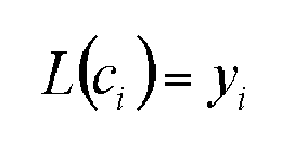
- Another simplification can be made when computing the expression


- According to one particular embodiment of the invention, each first decoder implements only the initializing steps 1, 2 and 3 of the belief propagation algorithm. Thus, each first decoding of a group (or triplet of packets y1, y2 and yRi) has, at output of each first LDPC decoder (401, 402,...40n), a corresponding vector which is a vector of likelihood logarithm values respectively (L1, L2,...Ln). Indeed, each vector of the likelihood values Li is the concatenation of the likelihood vectors of the packets y1, y2 and yRi. These vectors Li are obtained from application of the
steps equation 1. Should one of the packets y1, y2 and yRi be missing before the first decoding, the initial values of the likelihood logarithm of the missing packet are initialized with the value zero. - These computed values of likelihood logarithms (L1, L2...Ln) are then added up, bit by bit, by means of an
addition block 404. The result Lr generated at output of this addition block is then a vector sized 3∗N if each group has three packets. - This result Lr is then used by the
second LDPC decoder 405. Just like thefirst LDPC decoders second LDPC decoder 405 uses the parity matrix HH to carry out its decoding. Indeed the packets b1, b2 and b3=bl XOR b2 meet the following equation:
- Or else again : HH . B = zeros(K+K+N,1) with B = [b1;b2;b1 xor b2]
-
Figure 5 provides a schematic illustration of adecoding method 500 implemented by thedecoder 400 ofFigure 4 , thisdecoder 400 being implanted at the destination node 305 (Figure 5 ). - A
first step 501 is a step for initializing thedecoder 400. - A
second step 502 enables the reception of: - of at least two non-combined data packets (i.e. transmitted directly by the
source nodes Figure 3 ) and ; - n combined packets YR1, YR2,... YRn (i.e. the packets generated and transmitted by n relay nodes along the n relay nodes belonging to the meshed network) .
- A
third step 503 then determines n groups of packets (or n triplets), each nth group (or triplet) comprising at least two non-combined packets and one combined nth packet. - Then, in a
step 504, a first LDPC decoding (as explained in greater detail hereabove) with application of the Tanner graph and a "belief propagation" algorithm is performed for each of the groups in order to compute a value of a likelihood logarithm Li associated with a group i among the set of groups of packets (or triplets). - This first LDPC decoding is then performed on the basis of each triplet of packets and from the matrix HH introduced here above.
- A
step 505 is then used for the adding up of the likelihood logarithm values by means of theaddition block 404 inFigure 4 . We then obtain a sum vector Lr of the likelihood logarithms. - Then, in a
step 506, a second LDPC decoding is performed using the sum vector Lr of the likelihood logarithms. This second decoding is done by thesecond decoder 405 ofFigure 4 . This decoder, like the first decoders of thestep 504, uses the parity matrix HH to perform the second decoding. -
Figure 6 is a schematic illustration of the graphic progress of the bit error rate or BER as a function of the signal-to-noise ratio (or SNR) for: - decoding without relay nodes (represented by squares on a curve 3) ;
- a classic decoding with two relay nodes (represented by circles on a curve 2);
- a decoding with two relay nodes (represented by stars on a curve 1), according to a particular embodiment of the present invention.
- The curve of
Figure 6 clearly shows that, for a decoding with two relay nodes, the bit error rate obtained according to the method of the present invention (Figure 5 , curve 1) is smaller than that obtained with the classic method (curve 2), and that this is so for the same values of the signal-to-noise ratio. - The classic LDPC decoding, in a meshed network, of two source packets and two combined packets coming from two relay nodes corresponds to an LDPC decoding performed with the following matrix (i.e. without a first decoding with an estimation of the logarithmic values of each group of data packets, these values being then used for a second LDPC decoding).

- In this classic decoding, the LDPC decoding is therefore done with the matrix HHH and an input vector [Y1 Y2; YR1; YR2] (in the example of
figure 3 with reception of two combined packets YR1 and YR2). - In this example, a correlation (or likelihood) appears between the last two rows of the matrix HHH corresponding to the rows for the decoding of the two packets coming from the two relay nodes.
- In this example of a matrix, for a given configuration of a communications network, this correlation between rows is presented solely when each of the relay nodes does a same linear combination of the source data packets. As discussed here above, a decoding (for example an LDPC decoding) that is done with such a matrix presents a bit error rate that is greater than that of an ideal decoding matrix HHH for which the rows and columns would not be correlated with one another.
- This correlation of rows and columns of the decoding matrix is especially sensitive for an LDPC type decoding requiring a hollow matrix, i.e. a matrix with low correlation between the rows and columns.
- Again, this value of the bit error rate is appreciably lower if it is compared with the value obtained for an LDPC decoding without relay nodes (curve 3) performed with the matrix H and a packet b1.
- It must be noted that the simulation has been done with a BPSK (Binary Phase Shift Keying) modulation.
-
Figure 7 is a schematic illustration of acommunications device 700 adapted to implementing the method ofFigur 5 - This
communication device 700 comprises: - a
block 713 used to execute the method 500 (figure 5 ) . Thisblock 713 contains theblocks - a "CPU IF" block 711 corresponding to the interface between the CPU and the baseband part;
- a
block 712 corresponding to the data memory; - a
block 718 corresponding to a data packet reception circuit; - a
block 719 corresponding to a data packet reception circuit; - a
block 730 corresponding to a random-access memory (RAM); - a
block 740 corresponding to a read-only memory (ROM); - a
block 750 corresponding to a radiofrequency transmitter; - a
block 760 corresponding to a central processing unit (CPU). - It will be noted that the invention is not limited to a purely software implantation in the form of a sequence of instructions of a computer program but that it can also be implemented in hardware form or any other form combining a hardware part and a software part. Should the invention be implanted partially or totally in software form, the corresponding sequence of instructions could be stored in a detachable storage means (such as for example a floppy, a CD-ROM or a DVD-ROM) or in a non-detachable storage means, this storage means being readable by a computer or a microprocessor.
- Thus, the invention can be implemented equally well as a program executed:
- on a reprogrammable computation machine such as a personal computer (or PC), a digital signal processor (or DSP) or a microcontroller;
- or else again on a dedicated computation machine such as a set of logic gates, for example a field programmable gate array (FPGA) or applications specific integrated circuit (ASIC).
Claims (12)
- Method for decoding a plurality of data packets received through a meshed communications network for the retrieval of source packets transmitted by one or more source nodes, the meshed communications network comprising relay nodes generating combined packets, each combined packet consisting of a linear combination of source packets, the method being implemented by a destination node and being characterized in that it comprises steps for:- forming groups of received packets comprising combined packets, each group comprising no more than one packet among the combined packets consisting of a same linear combination of source packets;- performing (504), for each group, a first decoding of the packets of said group, said first decoding being performed by a first decoder implementing a belief propagation algorithm delivering a piece of likelihood information for said group;- combining (505) the pieces of likelihood information obtained by the first decoding performed for the different groups, to obtain a combination of pieces of likelihood information;- performing (506) a second decoding of said combination of pieces of likelihood information, said second decoding being performed by a second decoder capable of processing pieces of likelihood information.
- Method for decoding according to claim 1, characterized in that each group of received packets comprises the same set of at least one source packet.
- Method for decoding according to any one of the claims 1 and 2, characterized in that the first and second decoding operations are of the LDPC type.
- Method for decoding according to any one of the claims 1 to 3, characterized in that the first and second decodings are decodings in the logarithmic domain and in that the step for combining is a step of summation or weighted summation of each piece of trust information.
- Method for decoding according to any one of the claims 1 to 4, characterized in that each linear combination is done by means of an "Exclusive-OR" operation.
- Computer program product characterized in that it comprises program code instructions for implementing the method according to at least one of the claims 1 to 5, when said program is executed on a computer
- Computer-readable storage means storing a computer program comprising a set of instructions executable by a computer for implementing the method according to at least one of the claims 1 to 5.
- Destination node for decoding a plurality of data packets received through a meshed communications network for the retrieval of source packets transmitted by one or more source nodes, the meshed communications network comprising relay nodes generating combined packets, each combined packet consisting of a linear combination of source packets, said destination node being characterized in that it comprises:- means for forming groups of received packets comprising combined packets, each group comprising no more than one packet among the combined packets consisting of a same linear combination of source packets;- first means for decoding making it possible to perform, for each group, a first decoding of the packets of said group, said first decoding being performed by a first decoder implementing a belief propagation algorithm delivering a piece of likelihood information for said group;- means for combining the pieces of likelihood information obtained by the first decoding performed for the different groups, to obtain a combination of pieces of likelihood information;- second means for decoding to perform a second decoding of said combination of pieces of likelihood information, said second decoding being performed by a second decoder capable of processing pieces of likelihood information.
- Destination node according to claim 8, characterized in that it comprises means for selecting a same set of at least one source packet transmitted by said source node or nodes, each group of received packets comprising the same set of at least one source packet.
- Destination node according to one of the claims 8 and 9, characterized in that the first and second decoders perform LDPC type operations.
- Destination node according to any one of the claims 8 to 10, characterized in that the first and second decoders operate in the logarithmic domain and in that said means for combining pieces of likelihood information perform a summation or a weighted summation of each piece of trust information.
- Destination node according to any one of the claims 8 to 11, characterized in that each linear combination is done by means of an "Exclusive-OR" type operation.
Applications Claiming Priority (1)
| Application Number | Priority Date | Filing Date | Title |
|---|---|---|---|
| FR0957844A FR2952252B1 (en) | 2009-11-05 | 2009-11-05 | METHOD AND DEVICE FOR DECODING, COMPUTER PROGRAM PRODUCT, CORRESPONDING MEANS OF STORAGE AND CORRESPONDING DESTINATION NODE |
Publications (2)
| Publication Number | Publication Date |
|---|---|
| EP2323263A1 true EP2323263A1 (en) | 2011-05-18 |
| EP2323263B1 EP2323263B1 (en) | 2012-05-09 |
Family
ID=42668744
Family Applications (1)
| Application Number | Title | Priority Date | Filing Date |
|---|---|---|---|
| EP10190051A Not-in-force EP2323263B1 (en) | 2009-11-05 | 2010-11-04 | Method and device for decoding, corresponding computer program product, storage means and destination node |
Country Status (4)
| Country | Link |
|---|---|
| US (1) | US8532143B2 (en) |
| EP (1) | EP2323263B1 (en) |
| AT (1) | ATE557475T1 (en) |
| FR (1) | FR2952252B1 (en) |
Cited By (2)
| Publication number | Priority date | Publication date | Assignee | Title |
|---|---|---|---|---|
| EP2582052A1 (en) * | 2011-10-10 | 2013-04-17 | LSI Corporation | LDPC decoding of composite codewords and sub-codewords |
| EP2582053A1 (en) * | 2011-10-10 | 2013-04-17 | LSI Corporation | Systems and methods for LDPC encoding with composite codewords and sub-codewords |
Families Citing this family (5)
| Publication number | Priority date | Publication date | Assignee | Title |
|---|---|---|---|---|
| US9148173B2 (en) * | 2012-03-30 | 2015-09-29 | California Institute Of Technology | Distributed reed-solomon codes for simple multiple access networks |
| US9112839B2 (en) * | 2012-12-22 | 2015-08-18 | Qualcomm Incorporated | Methods and apparatus for efficient wireless communication of file information |
| WO2015094037A1 (en) * | 2013-12-17 | 2015-06-25 | Telefonaktiebolaget L M Ericsson (Publ) | Decoding of a message and corresponding encoding of a message |
| US9524271B2 (en) * | 2014-01-10 | 2016-12-20 | Alcatel Lucent | Distributed computation of linear combinations in a network |
| US10623082B2 (en) * | 2017-01-16 | 2020-04-14 | University Of Florida Research Foundation, Incorporated | Joint fountain code and network coding for multiple-source-multiple-destination wireless communication |
Citations (2)
| Publication number | Priority date | Publication date | Assignee | Title |
|---|---|---|---|---|
| EP1729435A1 (en) * | 2005-06-01 | 2006-12-06 | NTT DoCoMo, Inc. | Communication relay apparatus |
| US20090252146A1 (en) * | 2008-04-03 | 2009-10-08 | Microsoft Corporation | Continuous network coding in wireless relay networks |
Family Cites Families (20)
| Publication number | Priority date | Publication date | Assignee | Title |
|---|---|---|---|---|
| FR2728092A1 (en) * | 1994-12-07 | 1996-06-14 | Philips Electronique Lab | METHOD FOR DECODING COMPRESSED IMAGES |
| US6873609B1 (en) * | 1999-11-02 | 2005-03-29 | Ipwireless, Inc. | Use of internet WEB technology for wireless internet access |
| US6597988B1 (en) * | 2000-09-22 | 2003-07-22 | Sirf Technology, Inc. | Network assisted pseudolite acquisition for enhanced GPS navigation |
| KR100893070B1 (en) * | 2002-09-19 | 2009-04-17 | 엘지전자 주식회사 | Method and apparatus for providing and receiving multicast service in wireless communication system |
| US7983246B2 (en) * | 2004-12-20 | 2011-07-19 | Lg Electronics Inc. | Multimedia access system |
| US7778978B2 (en) * | 2006-05-01 | 2010-08-17 | Nokia Siemens Networks Oy | Decoder for a system with H-ARQ with cross-packet coding |
| US8116242B2 (en) * | 2006-07-18 | 2012-02-14 | Motorola Mobility, Inc. | Receiver having multi-antenna log likelihood ratio generation with channel estimation error |
| US8464120B2 (en) * | 2006-10-18 | 2013-06-11 | Panasonic Corporation | Method and system for data transmission in a multiple input multiple output (MIMO) system including unbalanced lifting of a parity check matrix prior to encoding input data streams |
| WO2008151674A1 (en) * | 2007-06-15 | 2008-12-18 | Telefonaktiebolaget Lm Ericsson (Publ) | Method of discovering overlapping cells |
| EP2043391A1 (en) * | 2007-09-25 | 2009-04-01 | Nokia Siemens Networks Oy | Omitting UE ID on an enhanced RACH process |
| US8705345B2 (en) * | 2007-11-26 | 2014-04-22 | Iowa State University Research Foundation, Inc. | Network protection using network coding |
| KR100960115B1 (en) * | 2007-11-29 | 2010-05-27 | 한국전자통신연구원 | Mobile communication system and its tunnel management method |
| US8036240B2 (en) * | 2007-12-14 | 2011-10-11 | Microsoft Corporation | Software defined cognitive radio |
| EP2239857A4 (en) * | 2008-01-31 | 2011-02-16 | Panasonic Corp | RADIO COMMUNICATION DEVICE AND ERROR CORRECTION ENCODING METHOD |
| WO2009132709A1 (en) * | 2008-04-30 | 2009-11-05 | Nokia Siemens Networks Oy | Transmitting node b load status information in a self organising network |
| KR101632208B1 (en) * | 2008-11-07 | 2016-06-21 | 엘지전자 주식회사 | Method for transmitting a reference signal |
| KR101156164B1 (en) * | 2008-12-22 | 2012-06-18 | 한국전자통신연구원 | Terminal and base station in the carrier aggregation communication system, and call admission control method using these |
| FR2948246B1 (en) * | 2009-07-15 | 2011-09-09 | Canon Kk | METHOD AND DEVICE FOR ALLOCATING BANDWIDTH RELEASED IN A COMMUNICATION NETWORK, COMPUTER PROGRAM PRODUCT AND CORRESPONDING STORAGE MEDIUM |
| US8824364B2 (en) * | 2009-09-16 | 2014-09-02 | At&T Mobility Ii Llc | Targeting communications in a femtocell network |
| US9100897B2 (en) * | 2010-01-12 | 2015-08-04 | Samsung Electronics Co., Ltd. | System and method for efficient station identification |
-
2009
- 2009-11-05 FR FR0957844A patent/FR2952252B1/en not_active Expired - Fee Related
-
2010
- 2010-11-04 EP EP10190051A patent/EP2323263B1/en not_active Not-in-force
- 2010-11-04 AT AT10190051T patent/ATE557475T1/en active
- 2010-11-05 US US12/940,243 patent/US8532143B2/en active Active
Patent Citations (2)
| Publication number | Priority date | Publication date | Assignee | Title |
|---|---|---|---|---|
| EP1729435A1 (en) * | 2005-06-01 | 2006-12-06 | NTT DoCoMo, Inc. | Communication relay apparatus |
| US20090252146A1 (en) * | 2008-04-03 | 2009-10-08 | Microsoft Corporation | Continuous network coding in wireless relay networks |
Non-Patent Citations (5)
| Title |
|---|
| AHMAD DARABIHA; ANTHONY CHAN CARUSONE; FRANK R. KSCHISCHANG: "A Bit-Serial Approximate Min-Sum LDPC Decoder and FPGA Implementation", IEEE INTERNATIONAL SYMPOSIUM ON CIRCUITS AND SYSTEMS, 2006 |
| DARABIHA A ET AL: "A Bit-Serial Approximate Min-Sum LDPC Decoder and FPGA Implementation", 2006 IEEE INTERNATIONAL SYMPOSIUM ON CIRCUITS AND SYSTEMS 21-24 MAY 2006 ISLAND OF KOS, GREECE, IEEE - PISCATAWAY, NJ, USA LNKD- DOI:10.1109/ISCAS.2006.1692544, 21 May 2006 (2006-05-21), pages 149 - 152, XP010938373, ISBN: 978-0-7803-9389-9 * |
| GEORG ZEITLER ET AL: "Design of network coding functions in multihop relay networks", TURBO CODES AND RELATED TOPICS, 2008 5TH INTERNATIONAL SYMPOSIUM ON, IEEE, PISCATAWAY, NJ, USA, 1 September 2008 (2008-09-01), pages 249 - 254, XP031353696, ISBN: 978-1-4244-2862-5 * |
| SARAH J JOHNSON ET AL: "Joint network and channel coding for cooperative networks", TELECOMMUNICATION NETWORKS AND APPLICATIONS CONFERENCE, 2007. ATNAC 2007. AUSTRALASIAN, IEEE, PISCATAWAY, NJ, USA, 2 December 2007 (2007-12-02), pages 435 - 440, XP031356775, ISBN: 978-1-4244-1557-1 * |
| SICHAO YANG ET AL: "Network Coding over a Noisy Relay : a Belief Propagation Approach", INFORMATION THEORY, 2007. ISIT 2007. IEEE INTERNATIONAL SYMPOSIUM ON, IEEE, PISCATAWAY, NJ, USA, 24 June 2007 (2007-06-24), pages 801 - 804, XP031281965, ISBN: 978-1-4244-1397-3 * |
Cited By (4)
| Publication number | Priority date | Publication date | Assignee | Title |
|---|---|---|---|---|
| EP2582052A1 (en) * | 2011-10-10 | 2013-04-17 | LSI Corporation | LDPC decoding of composite codewords and sub-codewords |
| EP2582053A1 (en) * | 2011-10-10 | 2013-04-17 | LSI Corporation | Systems and methods for LDPC encoding with composite codewords and sub-codewords |
| KR101440189B1 (en) | 2011-10-10 | 2014-09-12 | 엘에스아이 코포레이션 | Systems and methods for parity sharing data processing |
| TWI499221B (en) * | 2011-10-10 | 2015-09-01 | Avago Technologies General Ip | Systems and methods for parity shared data encoding |
Also Published As
| Publication number | Publication date |
|---|---|
| ATE557475T1 (en) | 2012-05-15 |
| US8532143B2 (en) | 2013-09-10 |
| FR2952252B1 (en) | 2011-12-09 |
| EP2323263B1 (en) | 2012-05-09 |
| US20110103402A1 (en) | 2011-05-05 |
| FR2952252A1 (en) | 2011-05-06 |
Similar Documents
| Publication | Publication Date | Title |
|---|---|---|
| EP2323263B1 (en) | Method and device for decoding, corresponding computer program product, storage means and destination node | |
| US10651973B2 (en) | Method and apparatus for error-correction encoding using a polar code | |
| CN110089037B (en) | Apparatus and method for polar code construction | |
| US7458009B2 (en) | Method for encoding low-density parity check code | |
| Trifonov | Design of polar codes for Rayleigh fading channel | |
| US8386880B2 (en) | Method for transmitting non-binary codes and decoding the same | |
| EP3628111B1 (en) | Method and apparatus for encoding based on layered polar code | |
| US10447435B2 (en) | Reduced-stage polar decoding | |
| EP2769500B1 (en) | Method and arrangement for conveying additional bits with an encoded data block in a communication system | |
| EP2391040B1 (en) | Method, device and program for configuring an overall encoding/decoding scheme in a communications network | |
| Vameghestahbanati et al. | Polar codes for SCMA systems | |
| KR20180090688A (en) | Method and apparatus for transmitting and receiving a signal using polar coding in a communication system | |
| Lechner et al. | Optimization of LDPC codes for receiver frontends | |
| KR101699749B1 (en) | Method for improved belief propagation decoding for short polar codes and the apparatus therefor | |
| Fominykh et al. | Comparative analysis of polar and LDPC codes in space and satellite communication systems | |
| Heloir et al. | Stochastic chase decoder for reed-solomon codes | |
| Takabe et al. | Asymptotic analysis on spatial coupling coding for two-way relay channels | |
| Shalin et al. | Differential properties of polar codes | |
| Lechner | Efficient decoding techniques for LDPC codes | |
| Gaurihar et al. | Design and implementation of LDPC codes and turbo codes using FPGA | |
| Rkizat et al. | Construction and iterative threshold decoding for low rates Quasi-Cyclic One Step Majority logic decodable codes | |
| Khodaiemehr et al. | Construction of full-diversity LDPC lattices for block-fading channels | |
| Djahanshahi et al. | Decoding on graphs: LDPC-Coded MISO systems and belief propagation | |
| Nguyen-Van et al. | Efficient LDPC Code Design based on Genetic Algorithm for IoT Applications | |
| Rkizat et al. | Iterative threshold decoding of Quasi-Cyclic One Step Majority logic decodable codes |
Legal Events
| Date | Code | Title | Description |
|---|---|---|---|
| PUAI | Public reference made under article 153(3) epc to a published international application that has entered the european phase |
Free format text: ORIGINAL CODE: 0009012 |
|
| AK | Designated contracting states |
Kind code of ref document: A1 Designated state(s): AL AT BE BG CH CY CZ DE DK EE ES FI FR GB GR HR HU IE IS IT LI LT LU LV MC MK MT NL NO PL PT RO RS SE SI SK SM TR |
|
| AX | Request for extension of the european patent |
Extension state: BA ME |
|
| 17P | Request for examination filed |
Effective date: 20110930 |
|
| GRAP | Despatch of communication of intention to grant a patent |
Free format text: ORIGINAL CODE: EPIDOSNIGR1 |
|
| RIC1 | Information provided on ipc code assigned before grant |
Ipc: H04B 7/155 20060101ALI20111018BHEP Ipc: H03M 13/11 20060101AFI20111018BHEP Ipc: H04L 1/00 20060101ALI20111018BHEP |
|
| GRAS | Grant fee paid |
Free format text: ORIGINAL CODE: EPIDOSNIGR3 |
|
| GRAA | (expected) grant |
Free format text: ORIGINAL CODE: 0009210 |
|
| AK | Designated contracting states |
Kind code of ref document: B1 Designated state(s): AL AT BE BG CH CY CZ DE DK EE ES FI FR GB GR HR HU IE IS IT LI LT LU LV MC MK MT NL NO PL PT RO RS SE SI SK SM TR |
|
| REG | Reference to a national code |
Ref country code: GB Ref legal event code: FG4D |
|
| REG | Reference to a national code |
Ref country code: AT Ref legal event code: REF Ref document number: 557475 Country of ref document: AT Kind code of ref document: T Effective date: 20120515 Ref country code: CH Ref legal event code: EP |
|
| REG | Reference to a national code |
Ref country code: IE Ref legal event code: FG4D |
|
| REG | Reference to a national code |
Ref country code: DE Ref legal event code: R096 Ref document number: 602010001468 Country of ref document: DE Effective date: 20120705 |
|
| REG | Reference to a national code |
Ref country code: NL Ref legal event code: VDEP Effective date: 20120509 |
|
| REG | Reference to a national code |
Ref country code: LT Ref legal event code: MG4D Effective date: 20120509 |
|
| PG25 | Lapsed in a contracting state [announced via postgrant information from national office to epo] |
Ref country code: IS Free format text: LAPSE BECAUSE OF FAILURE TO SUBMIT A TRANSLATION OF THE DESCRIPTION OR TO PAY THE FEE WITHIN THE PRESCRIBED TIME-LIMIT Effective date: 20120909 Ref country code: PL Free format text: LAPSE BECAUSE OF FAILURE TO SUBMIT A TRANSLATION OF THE DESCRIPTION OR TO PAY THE FEE WITHIN THE PRESCRIBED TIME-LIMIT Effective date: 20120509 Ref country code: FI Free format text: LAPSE BECAUSE OF FAILURE TO SUBMIT A TRANSLATION OF THE DESCRIPTION OR TO PAY THE FEE WITHIN THE PRESCRIBED TIME-LIMIT Effective date: 20120509 Ref country code: SE Free format text: LAPSE BECAUSE OF FAILURE TO SUBMIT A TRANSLATION OF THE DESCRIPTION OR TO PAY THE FEE WITHIN THE PRESCRIBED TIME-LIMIT Effective date: 20120509 Ref country code: RS Free format text: LAPSE BECAUSE OF FAILURE TO SUBMIT A TRANSLATION OF THE DESCRIPTION OR TO PAY THE FEE WITHIN THE PRESCRIBED TIME-LIMIT Effective date: 20120509 Ref country code: CY Free format text: LAPSE BECAUSE OF FAILURE TO SUBMIT A TRANSLATION OF THE DESCRIPTION OR TO PAY THE FEE WITHIN THE PRESCRIBED TIME-LIMIT Effective date: 20120509 Ref country code: NO Free format text: LAPSE BECAUSE OF FAILURE TO SUBMIT A TRANSLATION OF THE DESCRIPTION OR TO PAY THE FEE WITHIN THE PRESCRIBED TIME-LIMIT Effective date: 20120809 Ref country code: LT Free format text: LAPSE BECAUSE OF FAILURE TO SUBMIT A TRANSLATION OF THE DESCRIPTION OR TO PAY THE FEE WITHIN THE PRESCRIBED TIME-LIMIT Effective date: 20120509 |
|
| REG | Reference to a national code |
Ref country code: AT Ref legal event code: MK05 Ref document number: 557475 Country of ref document: AT Kind code of ref document: T Effective date: 20120509 |
|
| PG25 | Lapsed in a contracting state [announced via postgrant information from national office to epo] |
Ref country code: PT Free format text: LAPSE BECAUSE OF FAILURE TO SUBMIT A TRANSLATION OF THE DESCRIPTION OR TO PAY THE FEE WITHIN THE PRESCRIBED TIME-LIMIT Effective date: 20120910 Ref country code: HR Free format text: LAPSE BECAUSE OF FAILURE TO SUBMIT A TRANSLATION OF THE DESCRIPTION OR TO PAY THE FEE WITHIN THE PRESCRIBED TIME-LIMIT Effective date: 20120509 Ref country code: SI Free format text: LAPSE BECAUSE OF FAILURE TO SUBMIT A TRANSLATION OF THE DESCRIPTION OR TO PAY THE FEE WITHIN THE PRESCRIBED TIME-LIMIT Effective date: 20120509 Ref country code: GR Free format text: LAPSE BECAUSE OF FAILURE TO SUBMIT A TRANSLATION OF THE DESCRIPTION OR TO PAY THE FEE WITHIN THE PRESCRIBED TIME-LIMIT Effective date: 20120810 Ref country code: LV Free format text: LAPSE BECAUSE OF FAILURE TO SUBMIT A TRANSLATION OF THE DESCRIPTION OR TO PAY THE FEE WITHIN THE PRESCRIBED TIME-LIMIT Effective date: 20120509 |
|
| PG25 | Lapsed in a contracting state [announced via postgrant information from national office to epo] |
Ref country code: BE Free format text: LAPSE BECAUSE OF FAILURE TO SUBMIT A TRANSLATION OF THE DESCRIPTION OR TO PAY THE FEE WITHIN THE PRESCRIBED TIME-LIMIT Effective date: 20120509 |
|
| PG25 | Lapsed in a contracting state [announced via postgrant information from national office to epo] |
Ref country code: SK Free format text: LAPSE BECAUSE OF FAILURE TO SUBMIT A TRANSLATION OF THE DESCRIPTION OR TO PAY THE FEE WITHIN THE PRESCRIBED TIME-LIMIT Effective date: 20120509 Ref country code: DK Free format text: LAPSE BECAUSE OF FAILURE TO SUBMIT A TRANSLATION OF THE DESCRIPTION OR TO PAY THE FEE WITHIN THE PRESCRIBED TIME-LIMIT Effective date: 20120509 Ref country code: EE Free format text: LAPSE BECAUSE OF FAILURE TO SUBMIT A TRANSLATION OF THE DESCRIPTION OR TO PAY THE FEE WITHIN THE PRESCRIBED TIME-LIMIT Effective date: 20120509 Ref country code: CZ Free format text: LAPSE BECAUSE OF FAILURE TO SUBMIT A TRANSLATION OF THE DESCRIPTION OR TO PAY THE FEE WITHIN THE PRESCRIBED TIME-LIMIT Effective date: 20120509 Ref country code: AT Free format text: LAPSE BECAUSE OF FAILURE TO SUBMIT A TRANSLATION OF THE DESCRIPTION OR TO PAY THE FEE WITHIN THE PRESCRIBED TIME-LIMIT Effective date: 20120509 Ref country code: RO Free format text: LAPSE BECAUSE OF FAILURE TO SUBMIT A TRANSLATION OF THE DESCRIPTION OR TO PAY THE FEE WITHIN THE PRESCRIBED TIME-LIMIT Effective date: 20120509 Ref country code: NL Free format text: LAPSE BECAUSE OF FAILURE TO SUBMIT A TRANSLATION OF THE DESCRIPTION OR TO PAY THE FEE WITHIN THE PRESCRIBED TIME-LIMIT Effective date: 20120509 |
|
| PGFP | Annual fee paid to national office [announced via postgrant information from national office to epo] |
Ref country code: DE Payment date: 20121130 Year of fee payment: 3 |
|
| PG25 | Lapsed in a contracting state [announced via postgrant information from national office to epo] |
Ref country code: IT Free format text: LAPSE BECAUSE OF FAILURE TO SUBMIT A TRANSLATION OF THE DESCRIPTION OR TO PAY THE FEE WITHIN THE PRESCRIBED TIME-LIMIT Effective date: 20120509 |
|
| PLBE | No opposition filed within time limit |
Free format text: ORIGINAL CODE: 0009261 |
|
| STAA | Information on the status of an ep patent application or granted ep patent |
Free format text: STATUS: NO OPPOSITION FILED WITHIN TIME LIMIT |
|
| 26N | No opposition filed |
Effective date: 20130212 |
|
| PG25 | Lapsed in a contracting state [announced via postgrant information from national office to epo] |
Ref country code: ES Free format text: LAPSE BECAUSE OF FAILURE TO SUBMIT A TRANSLATION OF THE DESCRIPTION OR TO PAY THE FEE WITHIN THE PRESCRIBED TIME-LIMIT Effective date: 20120820 |
|
| REG | Reference to a national code |
Ref country code: DE Ref legal event code: R097 Ref document number: 602010001468 Country of ref document: DE Effective date: 20130212 |
|
| PG25 | Lapsed in a contracting state [announced via postgrant information from national office to epo] |
Ref country code: BG Free format text: LAPSE BECAUSE OF FAILURE TO SUBMIT A TRANSLATION OF THE DESCRIPTION OR TO PAY THE FEE WITHIN THE PRESCRIBED TIME-LIMIT Effective date: 20120809 |
|
| REG | Reference to a national code |
Ref country code: IE Ref legal event code: MM4A |
|
| PG25 | Lapsed in a contracting state [announced via postgrant information from national office to epo] |
Ref country code: IE Free format text: LAPSE BECAUSE OF NON-PAYMENT OF DUE FEES Effective date: 20121104 |
|
| PG25 | Lapsed in a contracting state [announced via postgrant information from national office to epo] |
Ref country code: MT Free format text: LAPSE BECAUSE OF FAILURE TO SUBMIT A TRANSLATION OF THE DESCRIPTION OR TO PAY THE FEE WITHIN THE PRESCRIBED TIME-LIMIT Effective date: 20120509 Ref country code: AL Free format text: LAPSE BECAUSE OF FAILURE TO SUBMIT A TRANSLATION OF THE DESCRIPTION OR TO PAY THE FEE WITHIN THE PRESCRIBED TIME-LIMIT Effective date: 20120509 |
|
| PG25 | Lapsed in a contracting state [announced via postgrant information from national office to epo] |
Ref country code: MC Free format text: LAPSE BECAUSE OF NON-PAYMENT OF DUE FEES Effective date: 20121130 Ref country code: TR Free format text: LAPSE BECAUSE OF FAILURE TO SUBMIT A TRANSLATION OF THE DESCRIPTION OR TO PAY THE FEE WITHIN THE PRESCRIBED TIME-LIMIT Effective date: 20120509 |
|
| PG25 | Lapsed in a contracting state [announced via postgrant information from national office to epo] |
Ref country code: SM Free format text: LAPSE BECAUSE OF FAILURE TO SUBMIT A TRANSLATION OF THE DESCRIPTION OR TO PAY THE FEE WITHIN THE PRESCRIBED TIME-LIMIT Effective date: 20120509 Ref country code: LU Free format text: LAPSE BECAUSE OF NON-PAYMENT OF DUE FEES Effective date: 20121104 |
|
| PG25 | Lapsed in a contracting state [announced via postgrant information from national office to epo] |
Ref country code: HU Free format text: LAPSE BECAUSE OF FAILURE TO SUBMIT A TRANSLATION OF THE DESCRIPTION OR TO PAY THE FEE WITHIN THE PRESCRIBED TIME-LIMIT Effective date: 20101104 |
|
| REG | Reference to a national code |
Ref country code: DE Ref legal event code: R119 Ref document number: 602010001468 Country of ref document: DE Effective date: 20140603 |
|
| PG25 | Lapsed in a contracting state [announced via postgrant information from national office to epo] |
Ref country code: DE Free format text: LAPSE BECAUSE OF NON-PAYMENT OF DUE FEES Effective date: 20140603 |
|
| REG | Reference to a national code |
Ref country code: CH Ref legal event code: PL |
|
| PG25 | Lapsed in a contracting state [announced via postgrant information from national office to epo] |
Ref country code: MK Free format text: LAPSE BECAUSE OF FAILURE TO SUBMIT A TRANSLATION OF THE DESCRIPTION OR TO PAY THE FEE WITHIN THE PRESCRIBED TIME-LIMIT Effective date: 20120509 Ref country code: LI Free format text: LAPSE BECAUSE OF NON-PAYMENT OF DUE FEES Effective date: 20141130 Ref country code: CH Free format text: LAPSE BECAUSE OF NON-PAYMENT OF DUE FEES Effective date: 20141130 |
|
| REG | Reference to a national code |
Ref country code: FR Ref legal event code: PLFP Year of fee payment: 6 |
|
| REG | Reference to a national code |
Ref country code: FR Ref legal event code: PLFP Year of fee payment: 7 |
|
| REG | Reference to a national code |
Ref country code: FR Ref legal event code: PLFP Year of fee payment: 8 |
|
| PGFP | Annual fee paid to national office [announced via postgrant information from national office to epo] |
Ref country code: FR Payment date: 20191126 Year of fee payment: 10 |
|
| PGFP | Annual fee paid to national office [announced via postgrant information from national office to epo] |
Ref country code: GB Payment date: 20191128 Year of fee payment: 10 |
|
| GBPC | Gb: european patent ceased through non-payment of renewal fee |
Effective date: 20201104 |
|
| PG25 | Lapsed in a contracting state [announced via postgrant information from national office to epo] |
Ref country code: FR Free format text: LAPSE BECAUSE OF NON-PAYMENT OF DUE FEES Effective date: 20201130 |
|
| PG25 | Lapsed in a contracting state [announced via postgrant information from national office to epo] |
Ref country code: GB Free format text: LAPSE BECAUSE OF NON-PAYMENT OF DUE FEES Effective date: 20201104 |