EP2323196A1 - Battery temperature unevenness suppressing power supply - Google Patents
Battery temperature unevenness suppressing power supply Download PDFInfo
- Publication number
- EP2323196A1 EP2323196A1 EP20100014029 EP10014029A EP2323196A1 EP 2323196 A1 EP2323196 A1 EP 2323196A1 EP 20100014029 EP20100014029 EP 20100014029 EP 10014029 A EP10014029 A EP 10014029A EP 2323196 A1 EP2323196 A1 EP 2323196A1
- Authority
- EP
- European Patent Office
- Prior art keywords
- thermally
- insulating member
- batteries
- power supply
- supply device
- Prior art date
- Legal status (The legal status is an assumption and is not a legal conclusion. Google has not performed a legal analysis and makes no representation as to the accuracy of the status listed.)
- Withdrawn
Links
- 238000001816 cooling Methods 0.000 claims abstract description 142
- 230000007246 mechanism Effects 0.000 claims abstract description 19
- 230000008878 coupling Effects 0.000 claims description 50
- 238000010168 coupling process Methods 0.000 claims description 50
- 238000005859 coupling reaction Methods 0.000 claims description 50
- 230000004308 accommodation Effects 0.000 claims description 30
- 238000003780 insertion Methods 0.000 claims description 12
- 230000037431 insertion Effects 0.000 claims description 12
- 230000007423 decrease Effects 0.000 claims description 9
- 239000002826 coolant Substances 0.000 claims description 7
- 230000000694 effects Effects 0.000 description 9
- 238000009413 insulation Methods 0.000 description 8
- 239000000463 material Substances 0.000 description 7
- 238000000034 method Methods 0.000 description 7
- 230000006866 deterioration Effects 0.000 description 6
- 238000011144 upstream manufacturing Methods 0.000 description 5
- 229910052782 aluminium Inorganic materials 0.000 description 4
- XAGFODPZIPBFFR-UHFFFAOYSA-N aluminium Chemical compound [Al] XAGFODPZIPBFFR-UHFFFAOYSA-N 0.000 description 4
- 230000009467 reduction Effects 0.000 description 4
- 230000035939 shock Effects 0.000 description 4
- 230000008859 change Effects 0.000 description 3
- 238000010276 construction Methods 0.000 description 3
- 238000010586 diagram Methods 0.000 description 3
- 239000007789 gas Substances 0.000 description 3
- 239000011347 resin Substances 0.000 description 3
- 229920005989 resin Polymers 0.000 description 3
- HBBGRARXTFLTSG-UHFFFAOYSA-N Lithium ion Chemical compound [Li+] HBBGRARXTFLTSG-UHFFFAOYSA-N 0.000 description 2
- 230000008901 benefit Effects 0.000 description 2
- 239000000112 cooling gas Substances 0.000 description 2
- 238000007599 discharging Methods 0.000 description 2
- 239000012777 electrically insulating material Substances 0.000 description 2
- 239000000446 fuel Substances 0.000 description 2
- 229910001416 lithium ion Inorganic materials 0.000 description 2
- 229910052751 metal Inorganic materials 0.000 description 2
- 239000002184 metal Substances 0.000 description 2
- 239000007769 metal material Substances 0.000 description 2
- 230000001172 regenerating effect Effects 0.000 description 2
- 238000007493 shaping process Methods 0.000 description 2
- 125000006850 spacer group Chemical group 0.000 description 2
- 238000010792 warming Methods 0.000 description 2
- 230000001133 acceleration Effects 0.000 description 1
- 229920000122 acrylonitrile butadiene styrene Polymers 0.000 description 1
- OJIJEKBXJYRIBZ-UHFFFAOYSA-N cadmium nickel Chemical compound [Ni].[Cd] OJIJEKBXJYRIBZ-UHFFFAOYSA-N 0.000 description 1
- 239000012809 cooling fluid Substances 0.000 description 1
- 238000005868 electrolysis reaction Methods 0.000 description 1
- 239000001257 hydrogen Substances 0.000 description 1
- 229910052739 hydrogen Inorganic materials 0.000 description 1
- 230000006872 improvement Effects 0.000 description 1
- 238000002347 injection Methods 0.000 description 1
- 239000007924 injection Substances 0.000 description 1
- 238000004519 manufacturing process Methods 0.000 description 1
- 230000004048 modification Effects 0.000 description 1
- 238000012986 modification Methods 0.000 description 1
- 229920003023 plastic Polymers 0.000 description 1
- 230000008569 process Effects 0.000 description 1
- 239000000243 solution Substances 0.000 description 1
- 238000009423 ventilation Methods 0.000 description 1
- XLYOFNOQVPJJNP-UHFFFAOYSA-N water Substances O XLYOFNOQVPJJNP-UHFFFAOYSA-N 0.000 description 1
Images



Classifications
-
- H—ELECTRICITY
- H01—ELECTRIC ELEMENTS
- H01M—PROCESSES OR MEANS, e.g. BATTERIES, FOR THE DIRECT CONVERSION OF CHEMICAL ENERGY INTO ELECTRICAL ENERGY
- H01M10/00—Secondary cells; Manufacture thereof
- H01M10/60—Heating or cooling; Temperature control
- H01M10/61—Types of temperature control
- H01M10/613—Cooling or keeping cold
-
- H—ELECTRICITY
- H01—ELECTRIC ELEMENTS
- H01M—PROCESSES OR MEANS, e.g. BATTERIES, FOR THE DIRECT CONVERSION OF CHEMICAL ENERGY INTO ELECTRICAL ENERGY
- H01M10/00—Secondary cells; Manufacture thereof
- H01M10/60—Heating or cooling; Temperature control
- H01M10/61—Types of temperature control
- H01M10/617—Types of temperature control for achieving uniformity or desired distribution of temperature
-
- H—ELECTRICITY
- H01—ELECTRIC ELEMENTS
- H01M—PROCESSES OR MEANS, e.g. BATTERIES, FOR THE DIRECT CONVERSION OF CHEMICAL ENERGY INTO ELECTRICAL ENERGY
- H01M10/00—Secondary cells; Manufacture thereof
- H01M10/60—Heating or cooling; Temperature control
- H01M10/62—Heating or cooling; Temperature control specially adapted for specific applications
- H01M10/625—Vehicles
-
- H—ELECTRICITY
- H01—ELECTRIC ELEMENTS
- H01M—PROCESSES OR MEANS, e.g. BATTERIES, FOR THE DIRECT CONVERSION OF CHEMICAL ENERGY INTO ELECTRICAL ENERGY
- H01M10/00—Secondary cells; Manufacture thereof
- H01M10/60—Heating or cooling; Temperature control
- H01M10/64—Heating or cooling; Temperature control characterised by the shape of the cells
- H01M10/647—Prismatic or flat cells, e.g. pouch cells
-
- H—ELECTRICITY
- H01—ELECTRIC ELEMENTS
- H01M—PROCESSES OR MEANS, e.g. BATTERIES, FOR THE DIRECT CONVERSION OF CHEMICAL ENERGY INTO ELECTRICAL ENERGY
- H01M10/00—Secondary cells; Manufacture thereof
- H01M10/60—Heating or cooling; Temperature control
- H01M10/65—Means for temperature control structurally associated with the cells
- H01M10/655—Solid structures for heat exchange or heat conduction
- H01M10/6556—Solid parts with flow channel passages or pipes for heat exchange
- H01M10/6557—Solid parts with flow channel passages or pipes for heat exchange arranged between the cells
-
- H—ELECTRICITY
- H01—ELECTRIC ELEMENTS
- H01M—PROCESSES OR MEANS, e.g. BATTERIES, FOR THE DIRECT CONVERSION OF CHEMICAL ENERGY INTO ELECTRICAL ENERGY
- H01M10/00—Secondary cells; Manufacture thereof
- H01M10/60—Heating or cooling; Temperature control
- H01M10/65—Means for temperature control structurally associated with the cells
- H01M10/656—Means for temperature control structurally associated with the cells characterised by the type of heat-exchange fluid
- H01M10/6561—Gases
- H01M10/6563—Gases with forced flow, e.g. by blowers
-
- H—ELECTRICITY
- H01—ELECTRIC ELEMENTS
- H01M—PROCESSES OR MEANS, e.g. BATTERIES, FOR THE DIRECT CONVERSION OF CHEMICAL ENERGY INTO ELECTRICAL ENERGY
- H01M10/00—Secondary cells; Manufacture thereof
- H01M10/60—Heating or cooling; Temperature control
- H01M10/65—Means for temperature control structurally associated with the cells
- H01M10/658—Means for temperature control structurally associated with the cells by thermal insulation or shielding
-
- H—ELECTRICITY
- H01—ELECTRIC ELEMENTS
- H01M—PROCESSES OR MEANS, e.g. BATTERIES, FOR THE DIRECT CONVERSION OF CHEMICAL ENERGY INTO ELECTRICAL ENERGY
- H01M50/00—Constructional details or processes of manufacture of the non-active parts of electrochemical cells other than fuel cells, e.g. hybrid cells
- H01M50/20—Mountings; Secondary casings or frames; Racks, modules or packs; Suspension devices; Shock absorbers; Transport or carrying devices; Holders
- H01M50/204—Racks, modules or packs for multiple batteries or multiple cells
- H01M50/207—Racks, modules or packs for multiple batteries or multiple cells characterised by their shape
- H01M50/209—Racks, modules or packs for multiple batteries or multiple cells characterised by their shape adapted for prismatic or rectangular cells
-
- H—ELECTRICITY
- H01—ELECTRIC ELEMENTS
- H01M—PROCESSES OR MEANS, e.g. BATTERIES, FOR THE DIRECT CONVERSION OF CHEMICAL ENERGY INTO ELECTRICAL ENERGY
- H01M50/00—Constructional details or processes of manufacture of the non-active parts of electrochemical cells other than fuel cells, e.g. hybrid cells
- H01M50/20—Mountings; Secondary casings or frames; Racks, modules or packs; Suspension devices; Shock absorbers; Transport or carrying devices; Holders
- H01M50/218—Mountings; Secondary casings or frames; Racks, modules or packs; Suspension devices; Shock absorbers; Transport or carrying devices; Holders characterised by the material
- H01M50/22—Mountings; Secondary casings or frames; Racks, modules or packs; Suspension devices; Shock absorbers; Transport or carrying devices; Holders characterised by the material of the casings or racks
- H01M50/222—Inorganic material
- H01M50/224—Metals
-
- Y—GENERAL TAGGING OF NEW TECHNOLOGICAL DEVELOPMENTS; GENERAL TAGGING OF CROSS-SECTIONAL TECHNOLOGIES SPANNING OVER SEVERAL SECTIONS OF THE IPC; TECHNICAL SUBJECTS COVERED BY FORMER USPC CROSS-REFERENCE ART COLLECTIONS [XRACs] AND DIGESTS
- Y02—TECHNOLOGIES OR APPLICATIONS FOR MITIGATION OR ADAPTATION AGAINST CLIMATE CHANGE
- Y02E—REDUCTION OF GREENHOUSE GAS [GHG] EMISSIONS, RELATED TO ENERGY GENERATION, TRANSMISSION OR DISTRIBUTION
- Y02E60/00—Enabling technologies; Technologies with a potential or indirect contribution to GHG emissions mitigation
- Y02E60/10—Energy storage using batteries
Definitions
- the present invention relates to a battery module that is composed of a plurality of batteries arranged side by side, and in particular to a power supply device that includes batteries and evens the temperatures of the batteries to be used for electric motors for driving hybrid cars, fuel cars, and electric vehicles.
- vehicle power supply devices In vehicle power supply devices, a large amount of current is repeatedly charged/discharged. Accordingly, vehicle power supply devices include a plurality of batteries arranged side by side. When vehicles are driven, the batteries generate heat. As a result, the temperatures of batteries will rise. If the batteries store the generated heat, the batteries will deteriorate in performance. For this reason, it is necessary to cool the batteries. In one of methods for cooling batteries, a cooling structure is constructed in such a power supply device, and cooling air is blown toward the cooling structure to cool the batteries. However, it is difficult to evenly cool the batteries.
- a power supply device cannot be used that is composed of a plurality of batteries serially connected to each other. For the aforementioned reason, although it is also important for vehicle power supply devices to bring batteries lower than a predetermined temperature, it is more important to control the temperatures of the batteries so as to evenly cool the batteries, which are arranged side by side, so that the temperature difference among the batteries is minimized.
- Battery cooling structures for evenly cooling batteries include a device box arranged on the upstream side of an inlet chamber, a wall surface of the device box facing the inlet chamber being constructed in various shapes.
- a battery cooling structure has been developed in Japanese Patent Laid-Open Publication No. 2007-250515 .
- a member with a protruding portion or a recessed portion is provided on the wall surface of the device box facing the inlet chamber so as to deflect a cooling air flow away from a battery pack so that cooling air is reduced that flows into cooling air paths on the upstream side and cooling air is increased that flows into cooling air paths on the downstream side whereby evening flow rates of cooling air in a battery module and reducing the temperature difference.
- a battery cooling structure has been developed that includes, instead of the air flow deflecting member that deflects a cooling air flow and is provided on the wall surface of the device box, a driven member that can be driven by an electric motor.
- the flow rate of cooling air can be adjusted based on a cooling requirement to reduce the temperature difference.
- a ventilation fan is provided with a larger amount of power to increase the flow rate of cooling gas.
- cooling air paths are not limited, the cooling air can flow either in longitudinal or traverse direction in cooling air paths.
- the air flow deflecting member is provided on a part of the device box on the upstream of the inlet chamber and deflects a cooling air flow so as to even the flow rates and reduce temperature unevenness.
- the air flow deflecting member requires shaping process or attachment process, there is a problem in that productivity will be low.
- material, shaping and assembling costs are required, there is a problem in that the production cost will be high.
- the deflection amount gets smaller toward the downstream of the inlet chamber. Accordingly, there is a disadvantage in that the effect will be limited that evens the flow rates in the battery module.
- this battery cooling structure is not suitable for a structure that includes a number of batteries connected to each other. If a number of air flow deflecting members are provided, pressure loss caused by the air flow deflecting members will be increased. In addition to this, it will be very difficult to optimize the arrangement, shape and the like of air flow deflecting members.
- this battery cooling structure will have the aforementioned problems and disadvantage, and additionally will have a possibility in that the flowing direction and the flow rate of cooling air may not be adjusted in the event of electric motor failure or the like. If the electric motor cannot be properly activated so that the air flow deflecting member is held retracted in the device box, a battery on the upstream of the inlet chamber may be over-cooled so that the output of this battery may be reduced. As a result, there is a problem in that the battery module may be affected as a whole.
- a power supply device includes a battery module, a cooling mechanism and a thermally-insulating member.
- the battery module is composed of a plurality of batteries arranged side by side.
- the cooling mechanism cools the batteries.
- the thermally-insulating member is arranged on a part of a surface of the battery module, and thermally insulates heat generated from at least one of the plurality of batteries.
- thermally-insulating member is in contact with the at least one of the plurality of batteries.
- a power supply device further includes an accommodation case that accommodates the battery module, and has inlet and outlet ports. Coolant that is moved by operation of the cooling mechanism flows through the inlet and outlet ports.
- the at least one of the plurality of batteries on or above which the thermally-insulating member is arranged is located in proximity to the inlet port.
- a power supply device further includes separators that are arranged between the batteries, and end plates that are arranged on the both ends of the battery module.
- the separators and the end plates have cooling paths through which the coolant flows from the inlet port.
- the thermally-insulating member closes some of the cooling paths.
- the thermally-insulating member extends over two or more batteries as the at least one of the plurality of batteries so that the contact areas between the two or more batteries and the thermally-insulating member decrease or get closer to constant with distance from the inlet port.
- a power supply device further includes coupling members that hold the end plates and the battery module.
- the end plates and the battery module are interposed between the ends of each of the coupling members.
- the thermally-insulating member is attached to the end plate or the coupling member.
- a power supply device further includes coupling members that hold the end plates and the battery module.
- the end plates and the battery module are interposed between the ends of each of the coupling members.
- the thermally-insulating member is attached to the end plate and the coupling member.
- the thermally-insulating member is attached to the end plate or the coupling member by a fit-in structure.
- the thermally-insulating member is attached to the end plate and the coupling member by a fit-in structure.
- the thermally-insulating member is arranged on a part of a surface of the battery module, for example, in the case where the thermally-insulating member is arranged in proximity to a battery that is likely to be cooled to a relatively lower temperature by the cooling mechanism, it is possible to suppress dissipation of heat generated by this battery. As a result, it is possible to bring this battery to a higher temperature. That is, since this battery is held warm by heat generated by this battery itself, it is possible to suppress unevenness of battery temperatures in the power supply device.
- the thermally-insulating member can be easily arranged in any types of power supply devices.
- the thermally-insulating member since the thermally-insulating member is in contact with the at least one battery, no gap is provided between the at least one battery and the thermally-insulating member. Accordingly, dissipation of the heat can be minimized. Therefore, improvement of the above effect can be expected.
- the thermally-insulating member can suppress the effect by the cooling mechanism on a battery that is likely to be cooled too much, it is possible to prevent that this battery is cooled too much.
- the thermally-insulating member is arranged on or above at least one battery located in proximity to the inlet port, it is possible to raise the temperature of a battery on the inlet port side that is generally likely to be lower as compared with on the outlet port side.
- the thermally-insulating member prevents that heat generated by a battery is dissipated out of the battery module. Therefore, it is possible reduce battery temperature unevenness in the power supply device.
- the temperatures of a plurality of batteries in proximity to the inlet port are likely to be lower, there is an advantage in that the thermally-insulating member can be collectively arranged over the plurality of batteries on the inlet port side.
- the thermally-insulating member closes some of the cooling paths of the separators and the end plates, batteries can be thermally insulated in accordance with thermal insulation requirements of the batteries the temperatures of which are likely to be relatively lower. Therefore, it is possible to minimize battery temperature unevenness, that is, to even battery temperatures.
- the thermally-insulating member closes the cooling paths so as not to allow the coolant to flow into the cooling paths, it is possible to prevent that the temperatures of the batteries become too low.
- the thermally-insulating member closes the cooling paths, it is not necessary to shape the separator and the end plate into different shapes. Accordingly, it is possible to provide commonality of parts. Therefore, it is possible to greatly reduce cost and man-hour.
- the thermally-insulating member covers two or more batteries so that the contact areas between the two or more batteries and the thermally-insulating member decrease or get closer to constant with distance from the inlet port, the levels of thermal insulation or cooling performance can be varied. If the contact areas are large, the number of closed cooling paths or the closed area of a cooling path of the end plate or the separator can be increased. As a result, it is possible to increase the thermal insulation effect on batteries in proximity to the inlet port. On the other hand, if the contact areas are small, the number of closed cooling paths or the closed area of a cooling path of the end plate or the separator adjacent to batteries away from the inlet port can be reduced.
- thermally-insulating member covers two or more batteries, there are advantages in that thermally-insulating members required for battery temperature unevenness reduction can be produced as the same structure, and in that the thermally-insulating member can be easily attached.
- the thermally-insulating member is attached to the end plate or the coupling member, an additional member is not required to hold the thermally-insulating member.
- the coupling member faces the plurality of batteries arranged side by side, the arrangement and the shape of the thermally-insulating member is not limited.
- the thermally-insulating member is attached to the end plate and the coupling member, the same effect as the sixth aspect of the present invention can be expected.
- the thermally-insulating member can be more securely and stably attached.
- the thermally-insulating member is attached to the end plate or the coupling member by a fit-in structure, the thermally-insulating member can be easily attached to the battery module. Therefore, it is possible to greatly reduce cost and man-hour as compared with attachment by a screw fastening structure or the like.
- the attachment part in the fit-in structure can be flat, it is possible to reduce pressure loss when cooling air or the like flows.
- the thermally-insulating member is attached to the end plate and the coupling member by a fit-in structure, the same effect as the eightheigth aspect of the present invention can be expected.
- the thermally-insulating member can be more securely and stably attached.
- a vehicle includes the aforementioned power supply device
- a battery module that can be simply constructed but can reduce the temperature unevenness ⁇ T in the battery module whereby increasing the life of the battery module.
- a vehicle that includes the aforementioned power supply device can be flexibly changed in design, this vehicle is suitable for frequent design change.
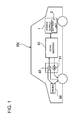
- Fig. 1 is a diagram showing an HV including a power supply device according to the present invention
- a power supply device can be installed on electric vehicles such as hybrid cars that are driven by both an engine and a motor, and electric vehicles that are driven only by a motor.
- the power supply device can be used as a power supply device for these types of vehicles. Exemplary cars including the power supply device are now described with reference to Figs. 1 and 2 .
- Fig. 1 is a block diagram showing an exemplary hybrid car (vehicle HV) that is driven both by an engine 80 and an electric motor 81, and includes a power supply device 1.
- the illustrated vehicle HV with the power supply device 1 includes the electric motor 81 and the engine 80 that drive the vehicle HV, the power supply device 1 including a battery unit 2 that supplies electric power to the electric motor 81, and an electric generator 82 that charges battery unit 2 of the power supply device 1.
- the power supply device 1 is connected to the electric motor 81 and the electric generator 82 via a DC/AC inverter 83.
- the vehicle HV is driven both by the electric motor 81 and the engine 80 with the battery unit 2 of the power supply device 1 being charged/discharged.
- the electric motor 81 is energized and drives the vehicle in a poor engine efficiency range, e.g., in acceleration or in a low speed range.
- the electric motor 81 is energized by electric power that is supplied from the power supply device 1.
- the electric generator 82 is driven by the engine 80 or by regenerative braking when users brake the vehicle so that the batteries 20 of the power supply device 1 are charged.
- Fig. 2 shows an exemplary electric vehicle (vehicle EV) that is driven only by an electric motor 81, and includes the power supply device 1.
- the illustrated vehicle EV with the power supply device 1 includes the electric motor 81 that drives the vehicle EV, the power supply device 1 that supplies electric power to the electric motor 81, and an electric generator 82 that charges battery unit 2 of the power supply device 1.
- the power supply device 1 is connected to the electric motor 81 and the electric generator 82 via a DC/AC inverter 83.
- the electric motor 81 is energized by electric power that is supplied from the power supply device 1.
- the electric generator 82 can be driven by vehicle EV regenerative braking so that the batteries 20 of the power supply device 1 are charged.
- the power supply device 1 according to an embodiment of the present invention to be installed in the aforementioned vehicles is now described with reference to Figs. 3 to 9 .
- Fig. 3 is a perspective view showing an accommodation case 4 that accommodates the battery unit 2 composed of later-discussed battery modules 3 (3a, 3b, 3c, 3d) of the power supply device 1 to be installed in a vehicle or the like.
- the accommodation case 4 has a case structure composed of sectionally rectangular U-shaped upper and lower cases 5 and 6, and rectangular side surface cases 7 and 8 on the both sides.
- the accommodation case 4 is formed of metal such as aluminum.
- the battery modules 3 are accommodated in the lower case 6 of the accommodation case 4.
- the upper case 5 covers the lower case 6.
- the battery modules 3 inside the accommodation case 4 are protected from shocks and pressures from the outside.
- one inlet port 10 is formed in the center of one side surface case 7 of the accommodation case 4, and communicates with the later-discussed battery modules 3 (3a, 3c). Cooling air (coolant) is blown by operation of a cooling mechanism (not shown), and flows through the inlet port 10 into the accommodation case 3.
- Outlet ports 11 are formed on the both ends of the one side surface case 7 to interpose the inlet port 10 between the outlet ports 11.
- the outlet ports 11 communicate with the later-discussed battery module 3s (3a, 3c).
- the cooling air is discharged through the outlet ports 11 from the accommodation case 4.
- an inlet port 10 and outlet ports 11 are formed on other side surface case 8 on the other side in the same arrangement as the one side surface case 7.
- inlet ports 10 and outlet ports 11 to similar to the side surface cases 7 and 8 are formed in the lower case 6 of the accommodation case 4 in positions that can communicate with the inlet and outlet ports 10 and 11 of the side surface cases 7 and 8.
- the cooling air flows through the inlet ports 10 into the accommodation case 4 and circulates along the peripheries of the batteries 20, which generate heat. After cooling the batteries, the cooling air is discharged through the outlet ports 11 from the accommodation case 4.
- the opening area of one inlet port 10 equals to the total opening area as the sum of the opening areas of the two outlet ports 11. Accordingly, the flow rate of the cooling air flowing through the inlet port 10 will equal to the total flow rate of the two outlet ports 11.
- air cooling type, air blower cooling mechanisms (fan etc.) are used as the cooling mechanism that cools the batteries 20, and forcedly blow cooling air through the inlet ports 10 toward the outlet ports 11.
- the cooling mechanism is not limited to the air cooling type, air blower cooling mechanism employed in this embodiment.
- various types cooling mechanisms can be employed such as air suction type cooling mechanism, water cooling type and coolant cooling type mechanisms, and the like.
- the cooling structure of the power supply device according to the present invention is not limited to the cooling structure that includes the inlet and outlet ports, and the like according to this embodiment.
- the present invention can be applied to power supply devices that include various types of cooling structures.
- Fig. 4 is a plan view showing the internal structure inside the lower case 6 as viewed from the top side of accommodation case 4 with the upper case 5 of the accommodation case 4 being removed.
- the power supply device 1 includes a high-output battery unit 2, which can supply high output voltage, and serves as a power supply that supplies electric power supply to the vehicle.
- the battery module the rectangular batteries can be connected to each other in parallel, or in combination of parallel and serial connection.
- the battery module may be composed of one battery.
- the accommodation case may include one battery module. The number of the battery modules inside the accommodation case is not limited.
- the power supply device 1 since a plurality of rectangular batteries 20 are connected to each other in series and are repeatedly charged/discharged at a large amount of current, the rectangular batteries 20 generate heat and increase in temperature. If the rectangular batteries 20 store the generated heat, the rectangular batteries 20 will deteriorate faster in performance. For this reason, it is necessary to cool the rectangular batteries 20. For this reason, the power supply device 1 shown in Fig. 4 includes the cooling structure for cooling the rectangular batteries 20. The following description will describe the cooling structure according to this embodiment.
- Cooling air paths 42 are formed in gaps between the plurality of rectangular batteries 20 arranged side by side. Cooling paths 55 are formed in gaps between batteries 20 and the end plates 50. When the cooling air passes through the cooling air paths 42 and 55, the rectangular batteries 20, which generate heat, are cooled. In addition, three flow paths are formed in the accommodation case 4. The cooling air flows through the three flow paths. One flow path among the three flow paths is an inlet flow path 12. The cooling air flows through the inlet flow path 12 before cooling batteries.
- the inlet flow path 12 communicates with the inlet ports 10, and faces side surfaces 21 of the plurality of rectangular batteries 20 arranged side by side.
- the inlet flow path 12 is formed in a part between battery modules 3 (3a and 3c) and in a part between battery modules (3b and 3d).
- the other two flow paths are outlet flow paths 13.
- the cooling air flows through the outlet flow paths 13 after cooling batteries.
- the outlet flow paths 13 communicate with the outlet ports 11, and face one side surfaces 21 of the plurality of rectangular batteries 20 arranged side by side.
- the outlet flow paths 13 are formed between the battery modules 3 and the lower case 6.
- the outlet flow paths 13 and the inlet flow path 12 are arranged in parallel to each other.
- Each of the outlet flow paths 13 and the inlet flow path 12 interpose battery modules 3 between them, and communicate with cooling air paths 42 and 55.
- Fig. 5 is a perspective view showing the outward appearance of one battery module 3a to be accommodated in the accommodation case 4.
- the battery module 3a includes a battery block 30 (30a), a pair of end plates 50, coupling members 60, and the thermally-insulating member 70.
- the rectangular battery 20 includes positive and negative electrode terminals 23 and 24.
- the battery block 30 (30a) includes a plurality of rectangular batteries 20 that are arranged side by side, and separators 40 that are sandwiched between the rectangular batteries 20.
- the end plates 50 are arranged on the both ends of the battery block 30 (30a).
- the coupling members 60 are attached to the end plates 50, and hold the battery block 30 (30a).
- the thermally-insulating member 70 is attached to one of the end plates 50 and two of the coupling members 60.
- the battery to be used for the battery module 3a is a rectangular flat-shaped battery 20.
- the corners of the battery are rounded. Since rectangular batteries can store energy at higher density per unit volume than cylindrical batteries, it is preferable that rectangular batteries be used in vehicles required to save space and to decrease in size.
- the rectangular battery 20 has a rectangular external shape.
- the width of the side surface 21 of the rectangular battery 20 is designed thin so that a plurality of rectangular batteries can be efficiently arranged side by side.
- the rectangular batteries 20 are lithium-ion rechargeable batteries, and have a large capacity relative to their weight and volume. Lithium-ion rechargeable batteries are suitable for a power source that drives the electric motor 81 for driving the vehicle.
- nickel-hydrogen batteries, nickel-cadmium batteries, fuel cells or the like can be used as the rectangular batteries.
- the rectangular battery 20 has terminal end parts slightly inward of the both ends of an upper surface 22. Positive and negative terminals 23 and 24 are mounted to the terminal end parts.
- the terminals 23 and 24 have a bolt shape that has threads with which nut 26 threadedly engages.
- a gas relief valve 25 is constructed at the center of the upper surface 22 of the rectangular battery 20.
- An electrolysis solution injection port (not shown) is formed between the negative electrode terminal 24 and the gas relief valve 25.
- the rectangular battery 20 has a metal exterior container.
- the rectangular batteries 20 are arranged side by side, and are electrically insulated from each other by the separators 40.
- the battery block 30a is composed of the rectangular batteries 20 and the separators 40.
- the rectangular batteries 20 are arranged side by side with the positive and negative terminals 23 and 24 being arranged on the upper surface 22 of the rectangular battery 20 at positions symmetrically with respect to a point.
- the rectangular batteries 20 are arranged side by side with the left and right of the rectangular batteries 20 being flipped, in other words, with the rectangular batteries 20 being flipped from side to side.
- the positive and negative terminals 23 and 24 of adjacent rectangular batteries are connected to each other by busbars 27.
- the rectangular batteries 20 are connected to each other in series.
- the busbar 27 lies astride and is in contact with these positive/negative electrode terminals 23 and 24.
- the nuts 26 are screwed onto the bolt threads of these terminals so that the busbar 27 is securely mounted to these terminals adjacent to each other.
- the positive and negative terminals 23 and 24 adjacent to each other are electrically connected to each other through the busbar 27.
- the separator 40 is formed of an electrically-insulating material such as plastic, and electrically insulates adjacent rectangular batteries 20 from each other.
- a battery-facing surface 41 of the separator facing the rectangular battery 20 has an external shape with substantially the same size as a surface of the rectangular battery 20.
- the width of the side surface of the separator is smaller than the side surfaces 21 of the rectangular battery 20.
- the separator 40 functions as a spacer that forms the cooling air paths 42 between rectangular batteries 20.
- three cooling air paths 42 are provided as a cooling structure in the separator 40 by forming the battery-facing surface 41 into a rectangular or trapezoidal wave shape in section.
- the number of the cooling air paths 42 is not limited to three but can be less than or more than three.
- the cooling air passes through the cooling air paths 42 so that the rectangular batteries 20, which generate heat, can be efficiently cooled. Since the rectangular batteries arranged side by side are efficiently cooled, it is possible to suppress deterioration of the rectangular batteries. Therefore, the performance of the rectangular batteries can be stable.
- the separator 40 has an external shape with an upper surface 44 and a bottom surface 45 perpendicular to the battery-facing surface 41.
- the separators 40 also serve to position batteries 20 so as to prevent deviation of adjacent batteries 20 relative to each other.
- batteries can be arranged side by side without separators to compose the battery module.
- the coupling members 60 are attached to the end plate 50, which are arranged on the both ends of the battery block 30a, from side surface sides.
- the side-by-side arranged rectangular batteries 20 of the battery block 30a are securely held in the side-by-side arrangement direction by bolts 62.
- the end plate 50 is formed of a metal material such as aluminum, and has an external shape with substantially the same size as the rectangular battery 20. However, the end plate may be formed of a resin material, or the like.
- the end plate 50 has recessed portions 52 at the four corner parts on a non-contact surface 51 that does not face a battery 20.
- the coupling members 60 are held in the recessed portions 52.
- Threaded holes 53 are formed at the center of the recessed portions 52. Since the recessed portions 52 are formed on the non-contact surface 51, it is possible to prevent that protruding parts appear on the non-contact surface 51. Even when the coupling members 60 are attached onto the non-contact surface 51, the non-contact surface 51 of the end plate 50 can be flat.
- the end plate 50 serves as a spacer that forms the cooling air paths 55 between rectangular batteries 20 similar to the separator 40.
- Three cooling air paths 55 are provided as a cooling structure on a contact surface 51 that faces the battery 20 by forming the contact surface 51 into a rectangular or trapezoidal wave shape in section.
- the cooling air flows through the cooling air paths 55 so that this rectangular battery 20, which generates heat, is efficiently cooled.
- the number of the cooling paths 55 can be less than three or more than three. Since the rectangular batteries 20 arranged side by side is efficiently cooled, it is possible to suppress deterioration of the rectangular batteries 20. Therefore, the performance of the rectangular batteries can be stable.
- the coupling member 60 is formed from an elongated plate-shaped metal material.
- the both ends of the coupling member 60 are bent at a right angle.
- the coupling member 60 has bent portions 61.
- a threaded hole is formed at the center of the bent portion 61.
- the coupling members 60 are placed in parallel to each other on the upper and lower parts of the both sides surfaces 21 of the rectangular batteries 20 arranged side by side of the battery block 30a that are coupled to the end plates 50.
- the bent portions 61 of the coupling member 60 are placed in the recessed portion 52 of the end plates 50. After that, the bolts 62 are inserted into and threadedly engage with the threaded holes 53 of a coupling portion 63.
- the rectangular batteries 20 are securely held by the coupling member 60. Since the recessed portions 52 are formed in attachment parts that receive the coupling members 60 on the non-contact surface 51, it is possible to prevent that the coupling members 60 deviated in the vertical direction. However, the arrangement, the number or the material of the coupling members for holding the battery block may be changed.
- the coupling members may be attached by an attachment method other than threaded engagement.
- cooling air is blown by operation of the cooling mechanism, and flows into the inlet ports 10. After that, the cooling air flows through the inlet flow path 12 into the cooling air paths 42 and 55.
- the flow rate of the cooling air increases as closer to the inlet port 10, and decreases with distance from the inlet port 10. For this reason, in this embodiment, a rectangular battery 20 in proximity to the inlet port 10 is likely to be cooled much and be over-cooled, while a rectangular battery 20 away from the inlet port 10 is likely to be inefficiently cooled and be over-heated. As a result, temperature unevenness ⁇ T is likely to appear among the rectangular batteries 20 in the accommodation case 4.
- ⁇ T can be obtained as the temperature difference by subtracting the lowest temperature from the highest temperature in the rectangular batteries 20 in the accommodation case 4. If such temperature unevenness appears when the batteries in the battery module are cooled, performance unevenness will also appear among the batteries. This unevenness will be increased as the batteries are used for long time. Accordingly, the charging/discharging capacities of the power supply device will decrease. Also, some of batteries will be easily overcharged/over-discharged, which in turn accelerates deterioration of the some batteries. Consequently, such unevenness may cause life reduction of the power supply device as a whole.
- ⁇ T Large temperature unevenness ⁇ T means that some of batteries may remarkably deteriorate. For this reason, in vehicle power supply devices, the deterioration of the some batteries results in a problem of the power supply device as a whole, and reduces the entire performance of the power supply device. If one of batteries cannot be used, a power supply device cannot be used that is composed of a plurality of batteries serially connected to each other. For the aforementioned reason, although it is also important for vehicle power supply devices to bring batteries lower than a predetermined temperature, it is more important to control the temperatures of the batteries so as to evenly cool the batteries, which are arranged side by side, so that the temperature difference ⁇ T among the batteries is minimized.
- the thermally-insulating member 70 is attached on a part of battery module 3 (3a, 3b, 3c, 3d) surface.
- the following description will describe exemplary attachment of the thermally-insulating member 70 onto the battery module 3 (3a, 3c) with reference to Figs. 6 to 9 .
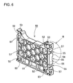
- Fig. 6 is an enlarged perspective view showing the outward appearance of the plate 50 onto which the thermally-insulating member 70 can be attached.
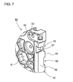
- Fig. 7 is an enlarged view showing an attachment part 78 (part B in Fig. 6 ) onto which the thermally-insulating member 70 can be attached.
- Two receiving portions 57 are formed on each of the both side surfaces 56 of the end plate 50.
- the thermally-insulating member 70 is attached into the receiving portions 57.
- the receiving portions 57 are located slightly inward of the recessed portions 52.
- the receiving portion 57 has a recessed shape.
- the side walls of the recessed shape are tapered so that the width of the recessed shape increases with distance from the side surface of the end plate side surface 56.
- the receiving portion 57 composes a fit-in structure.
- the recessed shape of the receiving portion 57 extends to the non-contact surface 51 of the end plate 50. Accordingly, as viewed from the non-contact surface 51 side, the receiving portion 57 of the end plate 50 has an external shape a truncated triangle shape (not shown). Since the receiving portion 57 composes the fit-in structure, the thermally-insulating member 70 can be firmly attached to the end plate 50. Therefore, the thermally-insulating member 70 can be less likely to be detached by shocks and the like.
- the end plate 50 according to this embodiment has a symmetrical shape with respect to a line. Therefore, it is possible to provide commonality of parts. However, the thermally-insulating member 70 can be attached by a method other than a fit-in structure. The arrangement, the number, the shape and the like of the fit-in structures are not limited.
- Fig. 8 is an enlarged perspective view showing the thermally-insulating member 70 to be attached to the end plate 50.
- the thermally-insulating member 70 shown in Fig. 8 has a thin rectangular plate shape.
- the thermally-insulating member 70 is formed of a resin material such as ABS resin.
- the thermally-insulating member 70 can be safely used.
- the thermally-insulating member 70 of resin material can be easily shaped.
- the material of the thermally-insulating member can be changed depending on the construction or the like of batteries to be used.
- a back side 72 refers to one surface of the thermally-insulating member 70 that faces the battery block 30 side.
- a front side 73 refers to the other surface that is opposite to the back side 72.
- Insertion portions 74 are formed on the back side 73 of the thermally-insulating member 70, and can be inserted into the receiving portions 57 of the end plate 50.
- the insertion portions 74 protrude from fit-in positions corresponding to the receiving portions 57 formed in the end plate 50, and have a shape that can be fitted into the recessed shape of the receiving portions 57.
- the insertion portions 74 are shaped as parts of the thermally-insulating member 70.
- the insertion portions 74 have an integral external shape with the thermally-insulating member 70.
- two hook portions 75 are formed on the thermally-insulating member 70, and have an L shape.
- the two hook portions 75 can be hooked on two coupling members 60 so that the thermally-insulating member 70 can be held on the two coupling members 60. Accordingly, the two hook portions 75 can prevent that the thermally-insulating member 70 flaps or are detached by shocks and the like.
- the hook portions 75 are arranged in one end part of the thermally-insulating member 70 opposite to the insertion portions 74. Similar to the insertion portions 74, the hook portions 75 are shaped as parts of the thermally-insulating member 70. Thus, the hook portions 75 have an integral external shape with the thermally-insulating member 70.
- the thermally-insulating member 70 has a cut-out portion 76 that is formed by cutting out a part of the thermally-insulating member 70.
- the shape of this cut-out portion 76 is designed depending on the cooled states the rectangular batteries 20 to be in contact with the thermally-insulating member 70.
- the opening of the cut-out portion 76 is reduced to increase the contact area with a rectangular battery 20 that is likely to be cooled much.
- the opening of the cut-out portion 76 is increased to reduce the contact area with a rectangular battery 20 that is likely to be inefficiently cooled.
- batteries can be thermally insulated from cooling air depending on heat insulation requirements of batteries that are likely to be cooled to a relatively low temperature.
- the thermally-insulating member without the cut-out portion closes cooling paths so that cooling air cannot flow into these closed cooling paths. Accordingly, it is not necessary to shape the separator and the end plate into different shapes. As a result, it is possible to provide commonality of parts. Therefore, it is possible to greatly reduce cost and man-hour.
- the levels of thermal insulation or cooling performance can be varied by adjusting the size of the cut-out portion.
- the thermally-insulating member 70 is provided with a supporting portion 77 that divides the cut-out portion 76. Since the supporting portion 77 divides the cut-out portion, a first cut-out portion 76a and a second cut-out portion 76b are formed on the both sides of the supporting portion 77.
- the supporting portion 77 has an elongated plate-shaped external shape with a width smaller than the battery side surfaces 21. As shown in Fig. 9 , the supporting portion 77 is in contact with the side surface 21 of a sixth rectangular battery 20 from the end plate 50 side.
- the first cut-out portion 76a includes an isosceles triangular part that has a vertex on a boundary between the end plate 50 and a battery 20 adjacent to the end plate 56, and a height extending from this vertex to the midpoint of the side surface 21 of a fifth battery 20.
- the vertex of the isosceles triangular part is rounded.
- the first cut-out portion 76a further includes a rectangular part that is defined by the bottom edge of the isosceles triangular part and a line that is obtained by moving this bottom edge to the supporting portion 77 in parallel.
- the second cut-out portion 76b gives rounded shapes to tails of the thermally-insulating member 70. Since the thermally-insulating member 70 according to this embodiment has a symmetrical external shape, the thermally-insulating member 70 will not produce a turbulent flow or an eddy in cooling air flowing through the inlet port 10. Therefore, the cooling air can smoothly flow.
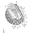
- Fig. 9 is an enlarged view showing an attachment part (a part A in Fig. 5 ) of the battery module 3 (3a, 3c) onto which the thermally-insulating member 70 is attached.
- the insertion portions 74 of the thermally-insulating member 70 are press-fitted into the receiving portions 57 of the end plate 50 from the non-contact surface 21 side of the end plate 50.
- the two hook portions 75 formed in the thermally-insulating member 70 are holed on and attached to the two coupling members 60.
- the thermally-insulating member 20 is partially sandwiched between the upper and lower coupling members 60, and the battery side surfaces 21.
- the thermally-insulating member 70 can be firmly attached.
- the thermally-insulating member 70 is attached to the end plate 50 and the coupling members 60, an additional component is not required for the attachment. Since the thermally-insulating member is attached by a fit-in structure, the thermally-insulating member can be easily attached to the battery module. Therefore, it is possible to greatly reduce cost and man-hour.
- the thermally-insulating member 70 is arranged substantially adjacent to the two coupling members 60, which horizontally extend in the upper and lower part of the battery side surface 21 in parallel to each other.
- the back side 72 of the thermally-insulating member 70 is arranged along the side-by-side arrangement direction of the end plates 50 and the batteries 20.
- the back side 72 of the thermally-insulating member 70 is in contact with the end plate side surface 56 and the battery side surfaces 21.
- the thermally-insulating member 70 is located closer to the rectangular batteries 20 than the coupling members 60. Since the thermally-insulating member 70 is in contact with the battery side surfaces 21 without gap, the thermally-insulating member 70 can cuts off dissipation from the battery module 3 (3a, 3c) of heat generated from the rectangular batteries 20.
- the heat is stored in the cooling air paths 42 and 55 of the separators 40 and the end plate 50 so that the rectangular batteries 20 are kept warm. Therefore, it is possible to raise the temperatures of the batteries. Consequently, it is possible to reduce battery temperature unevenness in the power supply device. In addition, since heat generated by a battery is effectively used to warm the battery, it is possible to reduce cost of warming a battery. Also, since cooling air is cut off that flows into the cooling air paths 42 and 55 so that the flow-in rate of the cooling air can be reduced, it is possible to prevent that batteries 20 near the inlet port 10 are over-cooled. However, the thermally-insulating member can be attached without contacting the batteries.
- the length of the thermally-insulating member 70 in the side-by-side arrangement direction of the rectangular battery 20 is about a third of the battery module 3 (the sum of the width of side surfaces 56 of the end plates 50, and six and half widths of side surfaces 21 of the rectangular batteries).
- the thermally-insulating member 20 is attached onto the battery module 3, the thermally-insulating member 20 is located inside the coupling members 60. As a result, even when the thermally-insulating member 70 is attached, the width of the inlet flow path 12 is not reduced. Therefore, pressure loss is prevented in the inlet flow path 12.
- a rectangular battery 20 in proximity to the inlet port 10 is likely to be over-cooled, while the temperatures of rectangular batteries 20 increase with distance from the inlet port 10.
- the thermally-insulating member 70 is arranged on the inlet port 10 side.
- the opening of the cut-out portion 76 increases with distance from the inlet port 10.
- the contact areas between the thermally-insulating member 70 and batteries 20 are adjusted by the cut-out portion 76 so that the temperature unevenness is reduced between a rectangular battery 20 in proximity to the inlet port 10 and a rectangular battery 20 away from the inlet port 10.
- a rectangular battery 20 in proximity to the end plate 50 is cooled by cold cooling air at high flow rate, and heat of this rectangular battery 20 is dissipated to the cold aluminum end plate 50.
- this rectangular battery 20 is likely to be over-cooled.
- the opening of the cut-out portion 76 is small on the rectangular battery 20 in proximity to the end plate 50 so that the heat insulation effect can be high in this battery 20.
- the temperatures of batteries increase with distance from end plate 50 on the inlet port 10 side.
- the opening area of the cut-out portion 76 gradually increases.
- the temperature difference between rectangular batteries 20 decreases with distance from the end plate 50. In this embodiment, sixth to the last batteries from the end plate 50 side will have almost no temperature difference among them.
- the opening area of the cut-out portion 76 of the thermally-insulating member 70 becomes almost constant in fifth to seventh batteries from the end plate 50 side.
- the contact areas between the thermally-insulating member 70 and rectangular batteries 20 are little varied in fifth to seventh batteries from the end plate 50 side.
- the cut-out portion 76 is not formed in a part of the thermally-insulating member 70 in contact with the end plate 50.
- the end plate 50 is not exposed to cooling air flowing through the inlet port 10. The reason is to prevent that the temperature of the battery 20 adjacent to the end plate 50 decreases much when the end plate 50 is cooled much by cooling air.
- the thermally-insulating member 70 is arranged only on the battery side surfaces 21 on one side, that is, only on a side of the battery module 3 that faces the inlet flow path 12 (see Fig. 4 ). The reason is that the thermally-insulating member 70 serves not only to thermally insulate heat generated from a rectangular battery 20 but also to reduce the flow rate of cooling air flowing from the inlet port 10.
- the arrangement, the number, the shape, the material and the attachment parts of thermally-insulating members are not limited to this embodiment. Any types of thermally-insulating members can be used for any types of battery modules composed of batteries.
- the attachment method of the thermally-insulating member and components to hold the thermally-insulating member are not limited to this embodiment.
- thermally-insulating members can be arranged on the both sides of the battery module in a modified embodiment.
- the thermally-insulating member can be attached to a component other than the end plate and the coupling member in another modified embodiment.
- the thermally-insulating member can be attached by a method other than the method using threaded engagement between the bolts and the threaded holes in another modified embodiment.
- the shape of the thermally-insulating member can be changed in still another modified embodiment.
- the power supply device has been described with reference to Figs. 5 and 9 showing the construction of the battery module 3 (3a).
- the thermally-insulating member 70 attached to the battery module 3 (3a, 3c) shown in Figs. 5 and 9 is flipped from the front side 73 to the back side 72.
- the insertion portions 74 of the flipped thermally-insulating member 70 are press-fitted into receiving portions 57 of the end plate 50 that have not received the thermally-insulating member 70 in the case of Figs. 5 and 9 .
- the arrangement of the thermally-insulating member can be easily changed.
- the same arrangement as the battery module 3a is applicable, arranged in 180° turned position.
- the power supply device can be produced at high productivity and can be suitably mass-produced. Therefore, the thus-constructed power supply device can be flexibly changed in design change is required.
- the present invention can be suitably applied to power supply devices for vehicles such as hybrid car and electric vehicle. Also, the present invention can be suitably applied to power supply devices other than vehicle power supply device. It should be apparent to those with an ordinary skill in the art that while various preferred embodiments of the invention have been shown and described, it is contemplated that the invention is not limited to the particular embodiments disclosed, which are deemed to be merely illustrative of the inventive concepts and should not be interpreted as limiting the scope of the invention, and which are suitable for all modifications and changes falling within the scope of the invention as defined in the appended claims.
Landscapes
- Chemical & Material Sciences (AREA)
- Chemical Kinetics & Catalysis (AREA)
- Electrochemistry (AREA)
- General Chemical & Material Sciences (AREA)
- Engineering & Computer Science (AREA)
- Manufacturing & Machinery (AREA)
- Battery Mounting, Suspending (AREA)
- Secondary Cells (AREA)
- Electric Propulsion And Braking For Vehicles (AREA)
Abstract
A power supply device is provided that includes a battery module 3 and a cooling mechanism. The battery module is composed of a plurality of batteries 20 arranged side by side. The cooling mechanism cools the batteries 20. A thermally-insulating member 70 is arranged on a part of a battery module surface, and thermally insulates heat generated from the batteries 3. This power supply device can reduce the temperature unevenness T.
Description
- The present invention relates to a battery module that is composed of a plurality of batteries arranged side by side, and in particular to a power supply device that includes batteries and evens the temperatures of the batteries to be used for electric motors for driving hybrid cars, fuel cars, and electric vehicles.
- In vehicle power supply devices, a large amount of current is repeatedly charged/discharged. Accordingly, vehicle power supply devices include a plurality of batteries arranged side by side. When vehicles are driven, the batteries generate heat. As a result, the temperatures of batteries will rise. If the batteries store the generated heat, the batteries will deteriorate in performance. For this reason, it is necessary to cool the batteries. In one of methods for cooling batteries, a cooling structure is constructed in such a power supply device, and cooling air is blown toward the cooling structure to cool the batteries. However, it is difficult to evenly cool the batteries. The reason is that a battery near the cooling air inlet is cooled by colder air at a higher flow rate and is likely to be over-cooled, while a battery the furthest away from the cooling air inlet is cooled at a lower flow rate relative to the battery on the cooling air inlet side and is likely to be poorly cooled so that the temperature difference among between the batteries will arise. For this reason, as the number of the batteries increases, it becomes more difficult to evenly cool the batteries, and the temperature difference will increase. In addition, if a cooling gas or fluid with large thermal capacity is used to increase cooling performance, the temperature difference will increase.
- If batteries are unevenly cooled, some of the batteries that are poorly cooled may deteriorate faster so that the lives of the some batteries may be reduced. In addition, this unevenness will be increased as the batteries are used for long time. Accordingly, the charging/discharging capacities of the power supply device will decrease. Also, the some batteries will be easily overcharged/over-discharged, which in turn accelerates deterioration of the some batteries. Consequently, such unevenness may cause life reduction of the power supply device as a whole. For this reason, in vehicle power supply devices, the deterioration of the some batteries results in a problem of the power supply device as a whole, and reduces the entire performance of the power supply device. If one of batteries cannot be used, a power supply device cannot be used that is composed of a plurality of batteries serially connected to each other. For the aforementioned reason, although it is also important for vehicle power supply devices to bring batteries lower than a predetermined temperature, it is more important to control the temperatures of the batteries so as to evenly cool the batteries, which are arranged side by side, so that the temperature difference among the batteries is minimized.
- Battery cooling structures for evenly cooling batteries are known that include a device box arranged on the upstream side of an inlet chamber, a wall surface of the device box facing the inlet chamber being constructed in various shapes. For example, a battery cooling structure has been developed in Japanese Patent Laid-Open Publication No.
2007-250515 - Specifically, in this battery cooling structure, a member with a protruding portion or a recessed portion is provided on the wall surface of the device box facing the inlet chamber so as to deflect a cooling air flow away from a battery pack so that cooling air is reduced that flows into cooling air paths on the upstream side and cooling air is increased that flows into cooling air paths on the downstream side whereby evening flow rates of cooling air in a battery module and reducing the temperature difference.
- Also, a battery cooling structure has been developed that includes, instead of the air flow deflecting member that deflects a cooling air flow and is provided on the wall surface of the device box, a driven member that can be driven by an electric motor. In this battery cooling structure, the flow rate of cooling air can be adjusted based on a cooling requirement to reduce the temperature difference.
- In addition, if the temperatures of the batteries become high, a ventilation fan is provided with a larger amount of power to increase the flow rate of cooling gas.
- In these types of cooling structures that changes the flowing direction and the flow rate of cooling air, since cooling air paths are not limited, the cooling air can flow either in longitudinal or traverse direction in cooling air paths.
- In the power supply device disclosed in the
JP 2007-250515 A - For this reason, this battery cooling structure is not suitable for a structure that includes a number of batteries connected to each other. If a number of air flow deflecting members are provided, pressure loss caused by the air flow deflecting members will be increased. In addition to this, it will be very difficult to optimize the arrangement, shape and the like of air flow deflecting members.
- Also, in the battery cooling structure that includes, instead of the air flow deflecting member that deflects a cooling air flow and is provided on the wall surface of the device box, a driven member that can be driven by an electric motor so that the flow rate of cooling air can be adjusted based on a cooling requirement to reduce the temperature difference, this battery cooling structure will have the aforementioned problems and disadvantage, and additionally will have a possibility in that the flowing direction and the flow rate of cooling air may not be adjusted in the event of electric motor failure or the like. If the electric motor cannot be properly activated so that the air flow deflecting member is held retracted in the device box, a battery on the upstream of the inlet chamber may be over-cooled so that the output of this battery may be reduced. As a result, there is a problem in that the battery module may be affected as a whole.
- In addition, in this cooling structure, since the flow rate is changed based on the battery cooling requirement, there is a disadvantage in that the position and state of a vortex area produced by the air flow deflecting member will change.
- It is an object pf the present invention to provide a power supply device that can be simply constructed in various types of structures but can reduce the temperature unevenness ΔT in the power supply device whereby increasing the life and ensuring the performance of the power supply device.
- To achieve the above object, a power supply device according to a first aspect of the present invention includes a battery module, a cooling mechanism and a thermally-insulating member. The battery module is composed of a plurality of batteries arranged side by side. The cooling mechanism cools the batteries. The thermally-insulating member is arranged on a part of a surface of the battery module, and thermally insulates heat generated from at least one of the plurality of batteries.
- In a power supply device according to a second aspect of the present invention, thermally-insulating member is in contact with the at least one of the plurality of batteries.
- A power supply device according to a third aspect of the present invention further includes an accommodation case that accommodates the battery module, and has inlet and outlet ports. Coolant that is moved by operation of the cooling mechanism flows through the inlet and outlet ports. The at least one of the plurality of batteries on or above which the thermally-insulating member is arranged is located in proximity to the inlet port.
- A power supply device according to a fourth aspect of the present invention further includes separators that are arranged between the batteries, and end plates that are arranged on the both ends of the battery module.
The separators and the end plates have cooling paths through which the coolant flows from the inlet port. The thermally-insulating member closes some of the cooling paths. - In a power supply device according to a fifth aspect of the present invention, the thermally-insulating member extends over two or more batteries as the at least one of the plurality of batteries so that the contact areas between the two or more batteries and the thermally-insulating member decrease or get closer to constant with distance from the inlet port.
- A power supply device according to a sixth aspect of the present invention further includes coupling members that hold the end plates and the battery module. The end plates and the battery module are interposed between the ends of each of the coupling members. The thermally-insulating member is attached to the end plate or the coupling member.
- A power supply device according to a seventh aspect of the present invention further includes coupling members that hold the end plates and the battery module. The end plates and the battery module are interposed between the ends of each of the coupling members. The thermally-insulating member is attached to the end plate and the coupling member.
- In a power supply device according to an eight aspect of the present invention, the thermally-insulating member is attached to the end plate or the coupling member by a fit-in structure.
- In a power supply device according to a ninth aspect of the present invention, the thermally-insulating member is attached to the end plate and the coupling member by a fit-in structure.
- According to the first aspect of the present invention, since the thermally-insulating member is arranged on a part of a surface of the battery module, for example, in the case where the thermally-insulating member is arranged in proximity to a battery that is likely to be cooled to a relatively lower temperature by the cooling mechanism, it is possible to suppress dissipation of heat generated by this battery. As a result, it is possible to bring this battery to a higher temperature. That is, since this battery is held warm by heat generated by this battery itself, it is possible to suppress unevenness of battery temperatures in the power supply device.
- Also, since heat generated by a battery is effectively used to warm the battery, it is possible to reduce cost of warming a battery. In addition, since the size and arrangement of the thermally-insulating member, and the type of cooling mechanism are not limited, the thermally-insulating member can be easily arranged in any types of power supply devices.
- According to the second aspect of the present invention, since the thermally-insulating member is in contact with the at least one battery, no gap is provided between the at least one battery and the thermally-insulating member. Accordingly, dissipation of the heat can be minimized. Therefore, improvement of the above effect can be expected. In addition, since the thermally-insulating member can suppress the effect by the cooling mechanism on a battery that is likely to be cooled too much, it is possible to prevent that this battery is cooled too much.
- According to the third aspect of the present invention, since the thermally-insulating member is arranged on or above at least one battery located in proximity to the inlet port, it is possible to raise the temperature of a battery on the inlet port side that is generally likely to be lower as compared with on the outlet port side. The thermally-insulating member prevents that heat generated by a battery is dissipated out of the battery module. Therefore, it is possible reduce battery temperature unevenness in the power supply device.
In addition, since the temperatures of a plurality of batteries in proximity to the inlet port are likely to be lower, there is an advantage in that the thermally-insulating member can be collectively arranged over the plurality of batteries on the inlet port side. - According to the fourth aspect of the present invention, since the thermally-insulating member closes some of the cooling paths of the separators and the end plates, batteries can be thermally insulated in accordance with thermal insulation requirements of the batteries the temperatures of which are likely to be relatively lower. Therefore, it is possible to minimize battery temperature unevenness, that is, to even battery temperatures. In addition, since the thermally-insulating member closes the cooling paths so as not to allow the coolant to flow into the cooling paths, it is possible to prevent that the temperatures of the batteries become too low. Also, since the thermally-insulating member closes the cooling paths, it is not necessary to shape the separator and the end plate into different shapes. Accordingly, it is possible to provide commonality of parts. Therefore, it is possible to greatly reduce cost and man-hour.
- According to the fifth aspect of the present invention, since the thermally-insulating member covers two or more batteries so that the contact areas between the two or more batteries and the thermally-insulating member decrease or get closer to constant with distance from the inlet port, the levels of thermal insulation or cooling performance can be varied. If the contact areas are large, the number of closed cooling paths or the closed area of a cooling path of the end plate or the separator can be increased. As a result, it is possible to increase the thermal insulation effect on batteries in proximity to the inlet port. On the other hand, if the contact areas are small, the number of closed cooling paths or the closed area of a cooling path of the end plate or the separator adjacent to batteries away from the inlet port can be reduced. As a result, it is possible to reduce the thermal insulation effect on these batteries. Consequently, it is possible to further reduce battery temperature unevenness. In addition, since the thermally-insulating member covers two or more batteries, there are advantages in that thermally-insulating members required for battery temperature unevenness reduction can be produced as the same structure, and in that the thermally-insulating member can be easily attached.
- According to the sixth aspect of the present invention, since the thermally-insulating member is attached to the end plate or the coupling member, an additional member is not required to hold the thermally-insulating member.
In addition, since the coupling member faces the plurality of batteries arranged side by side, the arrangement and the shape of the thermally-insulating member is not limited. - According to the seventh aspect of the present invention, since the thermally-insulating member is attached to the end plate and the coupling member, the same effect as the sixth aspect of the present invention can be expected. In addition, since the number of the attachment parts of the thermally-insulating member is increased, the thermally-insulating member can be more securely and stably attached.
- According to the eighth aspect of the present invention, since the thermally-insulating member is attached to the end plate or the coupling member by a fit-in structure, the thermally-insulating member can be easily attached to the battery module. Therefore, it is possible to greatly reduce cost and man-hour as compared with attachment by a screw fastening structure or the like. In addition, since the attachment part in the fit-in structure can be flat, it is possible to reduce pressure loss when cooling air or the like flows.
- According to the ninth aspect of the present invention, since the thermally-insulating member is attached to the end plate and the coupling member by a fit-in structure, the same effect as the eightheigth aspect of the present invention can be expected. In addition, since the number of the attachment parts of the fit-in structure is increased, the thermally-insulating member can be more securely and stably attached.
- In the case where a vehicle includes the aforementioned power supply device, it is possible to provide a battery module that can be simply constructed but can reduce the temperature unevenness ΔT in the battery module whereby increasing the life of the battery module. In addition, since a vehicle that includes the aforementioned power supply device can be flexibly changed in design, this vehicle is suitable for frequent design change.
The above and further objects of the present invention as well as the features thereof will become more apparent from the following detailed description to be made in conjunction with the accompanying drawings. -
Fig. 1 is a diagram showing an HV including a power supply device according to the present invention; -
Fig. 2 is a diagram showing an EV including a power supply device according to the present invention; -
Fig. 3 is a perspective view showing the outward appearance of an accommodation case that accommodates batteries of the power supply device according to the present invention; -
Fig. 4 is a plan view showing the internal structure of the batteries accommodated in the accommodation case; -
Fig. 5 is a perspective view showing the outward appearance of one battery module with a thermally-insulating member being attached to the battery module; -
Fig. 6 is an enlarged perspective view showing the outward appearance of one of end plates; -
Fig. 7 is an enlarged view showing a part B inFig. 6 ; -
Fig. 8 is an enlarged perspective view showing the thermally-insulating member to be attached to the battery module; and -
Fig. 9 is an enlarged view showing a part A inFig. 5 . - The following description will describe embodiments according to the present invention with reference to the
Figs. 1 to 9 . - A power supply device according to the present invention can be installed on electric vehicles such as hybrid cars that are driven by both an engine and a motor, and electric vehicles that are driven only by a motor. The power supply device can be used as a power supply device for these types of vehicles. Exemplary cars including the power supply device are now described with reference to
Figs. 1 and2 . -
Fig. 1 is a block diagram showing an exemplary hybrid car (vehicle HV) that is driven both by anengine 80 and anelectric motor 81, and includes a power supply device 1. The illustrated vehicle HV with the power supply device 1 includes theelectric motor 81 and theengine 80 that drive the vehicle HV, the power supply device 1 including abattery unit 2 that supplies electric power to theelectric motor 81, and anelectric generator 82 that chargesbattery unit 2 of the power supply device 1. The power supply device 1 is connected to theelectric motor 81 and theelectric generator 82 via a DC/AC inverter 83. The vehicle HV is driven both by theelectric motor 81 and theengine 80 with thebattery unit 2 of the power supply device 1 being charged/discharged. Theelectric motor 81 is energized and drives the vehicle in a poor engine efficiency range, e.g., in acceleration or in a low speed range. Theelectric motor 81 is energized by electric power that is supplied from the power supply device 1. Theelectric generator 82 is driven by theengine 80 or by regenerative braking when users brake the vehicle so that thebatteries 20 of the power supply device 1 are charged. -
Fig. 2 shows an exemplary electric vehicle (vehicle EV) that is driven only by anelectric motor 81, and includes the power supply device 1. The illustrated vehicle EV with the power supply device 1 includes theelectric motor 81 that drives the vehicle EV, the power supply device 1 that supplies electric power to theelectric motor 81, and anelectric generator 82 that chargesbattery unit 2 of the power supply device 1. The power supply device 1 is connected to theelectric motor 81 and theelectric generator 82 via a DC/AC inverter 83. Theelectric motor 81 is energized by electric power that is supplied from the power supply device 1. Theelectric generator 82 can be driven by vehicle EV regenerative braking so that thebatteries 20 of the power supply device 1 are charged. - The power supply device 1 according to an embodiment of the present invention to be installed in the aforementioned vehicles is now described with reference to
Figs. 3 to 9 . -
Fig. 3 is a perspective view showing anaccommodation case 4 that accommodates thebattery unit 2 composed of later-discussed battery modules 3 (3a, 3b, 3c, 3d) of the power supply device 1 to be installed in a vehicle or the like. Theaccommodation case 4 has a case structure composed of sectionally rectangular U-shaped upper andlower cases side surface cases accommodation case 4 is formed of metal such as aluminum. Thebattery modules 3 are accommodated in thelower case 6 of theaccommodation case 4. Theupper case 5 covers thelower case 6. Thebattery modules 3 inside theaccommodation case 4 are protected from shocks and pressures from the outside. - As shown in
Fig. 3 , oneinlet port 10 is formed in the center of oneside surface case 7 of theaccommodation case 4, and communicates with the later-discussed battery modules 3 (3a, 3c). Cooling air (coolant) is blown by operation of a cooling mechanism (not shown), and flows through theinlet port 10 into theaccommodation case 3. -
Outlet ports 11 are formed on the both ends of the oneside surface case 7 to interpose theinlet port 10 between theoutlet ports 11. Theoutlet ports 11 communicate with the later-discussed battery module 3s (3a, 3c). The cooling air is discharged through theoutlet ports 11 from theaccommodation case 4. - Also, an
inlet port 10 andoutlet ports 11 are formed on otherside surface case 8 on the other side in the same arrangement as the oneside surface case 7. In addition,inlet ports 10 andoutlet ports 11 to similar to theside surface cases lower case 6 of theaccommodation case 4 in positions that can communicate with the inlet andoutlet ports side surface cases - The cooling air flows through the
inlet ports 10 into theaccommodation case 4 and circulates along the peripheries of thebatteries 20, which generate heat. After cooling the batteries, the cooling air is discharged through theoutlet ports 11 from theaccommodation case 4. In the power supply device 1, the opening area of oneinlet port 10 equals to the total opening area as the sum of the opening areas of the twooutlet ports 11. Accordingly, the flow rate of the cooling air flowing through theinlet port 10 will equal to the total flow rate of the twooutlet ports 11. In the first embodiment, air cooling type, air blower cooling mechanisms (fan etc.) are used as the cooling mechanism that cools thebatteries 20, and forcedly blow cooling air through theinlet ports 10 toward theoutlet ports 11. - However, the cooling mechanism is not limited to the air cooling type, air blower cooling mechanism employed in this embodiment. For example, various types cooling mechanisms can be employed such as air suction type cooling mechanism, water cooling type and coolant cooling type mechanisms, and the like. The cooling structure of the power supply device according to the present invention is not limited to the cooling structure that includes the inlet and outlet ports, and the like according to this embodiment. The present invention can be applied to power supply devices that include various types of cooling structures.
-
Fig. 4 is a plan view showing the internal structure inside thelower case 6 as viewed from the top side ofaccommodation case 4 with theupper case 5 of theaccommodation case 4 being removed. - As shown in
Fig. 4 , four battery modules 3 (3a, 3b, 3c, 3d) are accommodated in theaccommodation case 4, and are arranged in parallel to each other in two columns and two rows.Rectangular batteries 20 are arranged side by side in each battery module. A total of 72batteries 20 inside theaccommodation case 4 are all serially connected to each other. Thus, the power supply device 1 includes a high-output battery unit 2, which can supply high output voltage, and serves as a power supply that supplies electric power supply to the vehicle. However, in the battery module, the rectangular batteries can be connected to each other in parallel, or in combination of parallel and serial connection. Alternatively, the battery module may be composed of one battery. Also, the accommodation case may include one battery module. The number of the battery modules inside the accommodation case is not limited. - In the power supply device 1, since a plurality of
rectangular batteries 20 are connected to each other in series and are repeatedly charged/discharged at a large amount of current, therectangular batteries 20 generate heat and increase in temperature. If therectangular batteries 20 store the generated heat, therectangular batteries 20 will deteriorate faster in performance. For this reason, it is necessary to cool therectangular batteries 20. For this reason, the power supply device 1 shown inFig. 4 includes the cooling structure for cooling therectangular batteries 20. The following description will describe the cooling structure according to this embodiment. - Cooling
air paths 42 are formed in gaps between the plurality ofrectangular batteries 20 arranged side by side. Coolingpaths 55 are formed in gaps betweenbatteries 20 and theend plates 50. When the cooling air passes through the coolingair paths rectangular batteries 20, which generate heat, are cooled. In addition, three flow paths are formed in theaccommodation case 4. The cooling air flows through the three flow paths. One flow path among the three flow paths is aninlet flow path 12. The cooling air flows through theinlet flow path 12 before cooling batteries. Theinlet flow path 12 communicates with theinlet ports 10, and faces side surfaces 21 of the plurality ofrectangular batteries 20 arranged side by side. Theinlet flow path 12 is formed in a part between battery modules 3 (3a and 3c) and in a part between battery modules (3b and 3d). - The other two flow paths are
outlet flow paths 13. The cooling air flows through theoutlet flow paths 13 after cooling batteries. Theoutlet flow paths 13 communicate with theoutlet ports 11, and face one side surfaces 21 of the plurality ofrectangular batteries 20 arranged side by side. Theoutlet flow paths 13 are formed between thebattery modules 3 and thelower case 6. Theoutlet flow paths 13 and theinlet flow path 12 are arranged in parallel to each other. Each of theoutlet flow paths 13 and theinlet flow path 12interpose battery modules 3 between them, and communicate with coolingair paths - That is, when the cooling air flows in the
accommodation case 4, after the cooling air passes through theinlet port 10, the cooling air flows into the coolingair paths inlet flow path 12. After efficiently cooling therectangular batteries 20, which face the coolingair paths air paths outlet flow paths 13. Finally, the cooling air is discharged through theoutlet ports 11 from theaccommodation case 4. Arrows inFig. 4 indicate paths of the cooling air inside theaccommodation case 4. However, although not illustrated, the arrangement and the numbers of the cooling air paths, the inlet flow paths, the outlet flow paths, the inlet ports and the outlet ports can be adjusted to suitable arrangement and numbers for the construction of power supply devices to be used. -
Fig. 5 is a perspective view showing the outward appearance of one battery module 3a to be accommodated in theaccommodation case 4. In the battery module 3a shown inFig. 5 , 18rectangular batteries 20 are arranged in the same orientation and are connected to each other in series. The battery module 3a includes a battery block 30 (30a), a pair ofend plates 50,coupling members 60, and the thermally-insulatingmember 70. Therectangular battery 20 includes positive andnegative electrode terminals rectangular batteries 20 that are arranged side by side, andseparators 40 that are sandwiched between therectangular batteries 20. Theend plates 50 are arranged on the both ends of the battery block 30 (30a). Thecoupling members 60 are attached to theend plates 50, and hold the battery block 30 (30a). The thermally-insulatingmember 70 is attached to one of theend plates 50 and two of thecoupling members 60. - The battery to be used for the battery module 3a is a rectangular flat-shaped
battery 20. The corners of the battery are rounded. Since rectangular batteries can store energy at higher density per unit volume than cylindrical batteries, it is preferable that rectangular batteries be used in vehicles required to save space and to decrease in size. Also, therectangular battery 20 has a rectangular external shape. The width of theside surface 21 of therectangular battery 20 is designed thin so that a plurality of rectangular batteries can be efficiently arranged side by side. Therectangular batteries 20 are lithium-ion rechargeable batteries, and have a large capacity relative to their weight and volume. Lithium-ion rechargeable batteries are suitable for a power source that drives theelectric motor 81 for driving the vehicle. However, nickel-hydrogen batteries, nickel-cadmium batteries, fuel cells or the like can be used as the rectangular batteries. - The
rectangular battery 20 has terminal end parts slightly inward of the both ends of anupper surface 22. Positive andnegative terminals terminals nut 26 threadedly engages. In addition, agas relief valve 25 is constructed at the center of theupper surface 22 of therectangular battery 20. An electrolysis solution injection port (not shown) is formed between thenegative electrode terminal 24 and thegas relief valve 25. - The
rectangular battery 20 has a metal exterior container. Therectangular batteries 20 are arranged side by side, and are electrically insulated from each other by theseparators 40. Thus, thebattery block 30a is composed of therectangular batteries 20 and theseparators 40. In thebattery block 30a, therectangular batteries 20 are arranged side by side with the positive andnegative terminals upper surface 22 of therectangular battery 20 at positions symmetrically with respect to a point. Therectangular batteries 20 are arranged side by side with the left and right of therectangular batteries 20 being flipped, in other words, with therectangular batteries 20 being flipped from side to side. The positive andnegative terminals busbars 27. Thus, therectangular batteries 20 are connected to each other in series. Thebusbar 27 lies astride and is in contact with these positive/negative electrode terminals busbar 27 is securely mounted to these terminals adjacent to each other. The positive andnegative terminals busbar 27. - The
separator 40 is formed of an electrically-insulating material such as plastic, and electrically insulates adjacentrectangular batteries 20 from each other. A battery-facingsurface 41 of the separator facing therectangular battery 20 has an external shape with substantially the same size as a surface of therectangular battery 20. The width of the side surface of the separator is smaller than the side surfaces 21 of therectangular battery 20. Theseparator 40 functions as a spacer that forms the coolingair paths 42 betweenrectangular batteries 20. To achieve this function, three coolingair paths 42 are provided as a cooling structure in theseparator 40 by forming the battery-facingsurface 41 into a rectangular or trapezoidal wave shape in section. However, the number of the coolingair paths 42 is not limited to three but can be less than or more than three. The cooling air passes through the coolingair paths 42 so that therectangular batteries 20, which generate heat, can be efficiently cooled. Since the rectangular batteries arranged side by side are efficiently cooled, it is possible to suppress deterioration of the rectangular batteries. Therefore, the performance of the rectangular batteries can be stable. - In addition, the
separator 40 has an external shape with anupper surface 44 and abottom surface 45 perpendicular to the battery-facingsurface 41. Thus, theseparators 40 also serve to positionbatteries 20 so as to prevent deviation ofadjacent batteries 20 relative to each other. However, in the case where the exterior container of the battery is formed of an electrically-insulating material, batteries can be arranged side by side without separators to compose the battery module. - The
coupling members 60 are attached to theend plate 50, which are arranged on the both ends of thebattery block 30a, from side surface sides. The side-by-side arrangedrectangular batteries 20 of thebattery block 30a are securely held in the side-by-side arrangement direction bybolts 62. - The
end plate 50 is formed of a metal material such as aluminum, and has an external shape with substantially the same size as therectangular battery 20. However, the end plate may be formed of a resin material, or the like. Theend plate 50 has recessedportions 52 at the four corner parts on anon-contact surface 51 that does not face abattery 20. Thecoupling members 60 are held in the recessedportions 52. Threadedholes 53 are formed at the center of the recessedportions 52. Since the recessedportions 52 are formed on thenon-contact surface 51, it is possible to prevent that protruding parts appear on thenon-contact surface 51. Even when thecoupling members 60 are attached onto thenon-contact surface 51, thenon-contact surface 51 of theend plate 50 can be flat. - The
end plate 50 serves as a spacer that forms the coolingair paths 55 betweenrectangular batteries 20 similar to theseparator 40. Three coolingair paths 55 are provided as a cooling structure on acontact surface 51 that faces thebattery 20 by forming thecontact surface 51 into a rectangular or trapezoidal wave shape in section. The cooling air flows through the coolingair paths 55 so that thisrectangular battery 20, which generates heat, is efficiently cooled. However, the number of the coolingpaths 55 can be less than three or more than three. Since therectangular batteries 20 arranged side by side is efficiently cooled, it is possible to suppress deterioration of therectangular batteries 20. Therefore, the performance of the rectangular batteries can be stable. - The
coupling member 60 is formed from an elongated plate-shaped metal material. The both ends of thecoupling member 60 are bent at a right angle. Thus, thecoupling member 60 has bentportions 61. In addition, a threaded hole is formed at the center of thebent portion 61. Thecoupling members 60 are placed in parallel to each other on the upper and lower parts of the both sides surfaces 21 of therectangular batteries 20 arranged side by side of thebattery block 30a that are coupled to theend plates 50. Thebent portions 61 of thecoupling member 60 are placed in the recessedportion 52 of theend plates 50. After that, thebolts 62 are inserted into and threadedly engage with the threadedholes 53 of acoupling portion 63. Thus, therectangular batteries 20 are securely held by thecoupling member 60. Since the recessedportions 52 are formed in attachment parts that receive thecoupling members 60 on thenon-contact surface 51, it is possible to prevent that thecoupling members 60 deviated in the vertical direction. However, the arrangement, the number or the material of the coupling members for holding the battery block may be changed. The coupling members may be attached by an attachment method other than threaded engagement. - As shown in
Fig. 4 , cooling air is blown by operation of the cooling mechanism, and flows into theinlet ports 10. After that, the cooling air flows through theinlet flow path 12 into the coolingair paths inlet port 10, and decreases with distance from theinlet port 10. For this reason, in this embodiment, arectangular battery 20 in proximity to theinlet port 10 is likely to be cooled much and be over-cooled, while arectangular battery 20 away from theinlet port 10 is likely to be inefficiently cooled and be over-heated. As a result, temperature unevenness ΔT is likely to appear among therectangular batteries 20 in theaccommodation case 4. ΔT can be obtained as the temperature difference by subtracting the lowest temperature from the highest temperature in therectangular batteries 20 in theaccommodation case 4. If such temperature unevenness appears when the batteries in the battery module are cooled, performance unevenness will also appear among the batteries. This unevenness will be increased as the batteries are used for long time. Accordingly, the charging/discharging capacities of the power supply device will decrease. Also, some of batteries will be easily overcharged/over-discharged, which in turn accelerates deterioration of the some batteries. Consequently, such unevenness may cause life reduction of the power supply device as a whole. - Large temperature unevenness ΔT means that some of batteries may remarkably deteriorate. For this reason, in vehicle power supply devices, the deterioration of the some batteries results in a problem of the power supply device as a whole, and reduces the entire performance of the power supply device. If one of batteries cannot be used, a power supply device cannot be used that is composed of a plurality of batteries serially connected to each other. For the aforementioned reason, although it is also important for vehicle power supply devices to bring batteries lower than a predetermined temperature, it is more important to control the temperatures of the batteries so as to evenly cool the batteries, which are arranged side by side, so that the temperature difference ΔT among the batteries is minimized.
- Accordingly, in the embodiment according to the present invention, as shown in
Fig. 5 , in order to raise the temperature of arectangular battery 20 in proximity to theinlet port 10, which is likely to be over-cooled, the thermally-insulatingmember 70 is attached on a part of battery module 3 (3a, 3b, 3c, 3d) surface. The following description will describe exemplary attachment of the thermally-insulatingmember 70 onto the battery module 3 (3a, 3c) with reference toFigs. 6 to 9 . -
Fig. 6 is an enlarged perspective view showing the outward appearance of theplate 50 onto which the thermally-insulatingmember 70 can be attached.Fig. 7 is an enlarged view showing an attachment part 78 (part B inFig. 6 ) onto which the thermally-insulatingmember 70 can be attached. Two receivingportions 57 are formed on each of the both side surfaces 56 of theend plate 50. The thermally-insulatingmember 70 is attached into the receivingportions 57. The receivingportions 57 are located slightly inward of the recessedportions 52. The receivingportion 57 has a recessed shape. The side walls of the recessed shape are tapered so that the width of the recessed shape increases with distance from the side surface of the endplate side surface 56. Thus, the receivingportion 57 composes a fit-in structure. The recessed shape of the receivingportion 57 extends to thenon-contact surface 51 of theend plate 50. Accordingly, as viewed from thenon-contact surface 51 side, the receivingportion 57 of theend plate 50 has an external shape a truncated triangle shape (not shown). Since the receivingportion 57 composes the fit-in structure, the thermally-insulatingmember 70 can be firmly attached to theend plate 50. Therefore, the thermally-insulatingmember 70 can be less likely to be detached by shocks and the like. Theend plate 50 according to this embodiment has a symmetrical shape with respect to a line. Therefore, it is possible to provide commonality of parts. However, the thermally-insulatingmember 70 can be attached by a method other than a fit-in structure. The arrangement, the number, the shape and the like of the fit-in structures are not limited. -
Fig. 8 is an enlarged perspective view showing the thermally-insulatingmember 70 to be attached to theend plate 50. The thermally-insulatingmember 70 shown inFig. 8 has a thin rectangular plate shape. The thermally-insulatingmember 70 is formed of a resin material such as ABS resin. Thus, the heat insulation effect of the thermally-insulatingmember 70 can be high. In addition, a short circuit does not occur between the thermally-insulatingmember 70 and other component. Therefore, the thermally-insulatingmember 70 can be safely used. Also, the thermally-insulatingmember 70 of resin material can be easily shaped. However, the material of the thermally-insulating member can be changed depending on the construction or the like of batteries to be used. - When the thermally-insulating
member 70 is attached onto thebattery module 3, aback side 72 refers to one surface of the thermally-insulatingmember 70 that faces thebattery block 30 side. Afront side 73 refers to the other surface that is opposite to theback side 72.Insertion portions 74 are formed on theback side 73 of the thermally-insulatingmember 70, and can be inserted into the receivingportions 57 of theend plate 50. Theinsertion portions 74 protrude from fit-in positions corresponding to the receivingportions 57 formed in theend plate 50, and have a shape that can be fitted into the recessed shape of the receivingportions 57. Theinsertion portions 74 are shaped as parts of the thermally-insulatingmember 70. Thus, theinsertion portions 74 have an integral external shape with the thermally-insulatingmember 70. - In addition, two
hook portions 75 are formed on the thermally-insulatingmember 70, and have an L shape. Thus, the twohook portions 75 can be hooked on twocoupling members 60 so that the thermally-insulatingmember 70 can be held on the twocoupling members 60. Accordingly, the twohook portions 75 can prevent that the thermally-insulatingmember 70 flaps or are detached by shocks and the like. Thehook portions 75 are arranged in one end part of the thermally-insulatingmember 70 opposite to theinsertion portions 74. Similar to theinsertion portions 74, thehook portions 75 are shaped as parts of the thermally-insulatingmember 70. Thus, thehook portions 75 have an integral external shape with the thermally-insulatingmember 70. - In addition, the thermally-insulating
member 70 has a cut-outportion 76 that is formed by cutting out a part of the thermally-insulatingmember 70. The shape of this cut-outportion 76 is designed depending on the cooled states therectangular batteries 20 to be in contact with the thermally-insulatingmember 70. The opening of the cut-outportion 76 is reduced to increase the contact area with arectangular battery 20 that is likely to be cooled much. The opening of the cut-outportion 76 is increased to reduce the contact area with arectangular battery 20 that is likely to be inefficiently cooled. In the case where the cut-out portion is formed, batteries can be thermally insulated from cooling air depending on heat insulation requirements of batteries that are likely to be cooled to a relatively low temperature. Therefore, it is possible to minimize battery temperature unevenness, that is, to even battery temperatures. Also, a part of the thermally-insulating member without the cut-out portion closes cooling paths so that cooling air cannot flow into these closed cooling paths. Accordingly, it is not necessary to shape the separator and the end plate into different shapes. As a result, it is possible to provide commonality of parts. Therefore, it is possible to greatly reduce cost and man-hour. In addition, the levels of thermal insulation or cooling performance can be varied by adjusting the size of the cut-out portion. - In order to prevent strength reduction of the thermally-insulating
member 70 caused by the cut-outportion 76, the thermally-insulatingmember 70 is provided with a supportingportion 77 that divides the cut-outportion 76. Since the supportingportion 77 divides the cut-out portion, a first cut-outportion 76a and a second cut-outportion 76b are formed on the both sides of the supportingportion 77. The supportingportion 77 has an elongated plate-shaped external shape with a width smaller than the battery side surfaces 21. As shown inFig. 9 , the supportingportion 77 is in contact with theside surface 21 of a sixthrectangular battery 20 from theend plate 50 side. - The first cut-out
portion 76a includes an isosceles triangular part that has a vertex on a boundary between theend plate 50 and abattery 20 adjacent to theend plate 56, and a height extending from this vertex to the midpoint of theside surface 21 of afifth battery 20. The vertex of the isosceles triangular part is rounded. The first cut-outportion 76a further includes a rectangular part that is defined by the bottom edge of the isosceles triangular part and a line that is obtained by moving this bottom edge to the supportingportion 77 in parallel. The second cut-outportion 76b gives rounded shapes to tails of the thermally-insulatingmember 70. Since the thermally-insulatingmember 70 according to this embodiment has a symmetrical external shape, the thermally-insulatingmember 70 will not produce a turbulent flow or an eddy in cooling air flowing through theinlet port 10. Therefore, the cooling air can smoothly flow. - The following description will describe attachment of the thermally-insulating
member 70 with reference toFig. 9 . -
Fig. 9 is an enlarged view showing an attachment part (a part A inFig. 5 ) of the battery module 3 (3a, 3c) onto which the thermally-insulatingmember 70 is attached. In attachment of the thermally-insulatingmember 70 onto thebattery module 3, first, theinsertion portions 74 of the thermally-insulatingmember 70 are press-fitted into the receivingportions 57 of theend plate 50 from thenon-contact surface 21 side of theend plate 50. Then, the twohook portions 75 formed in the thermally-insulatingmember 70 are holed on and attached to the twocoupling members 60. After that, the thermally-insulatingmember 20 is partially sandwiched between the upper andlower coupling members 60, and the battery side surfaces 21. Accordingly, even if vertical and horizontal vibrations or shocks are strongly applied to the thermally-insulatingmember 70, theinsertion portions 74 and thehook portions 75 are not disengaged. Therefore, the thermally-insulatingmember 70 can be firmly attached. In addition, since the thermally-insulatingmember 70 is attached to theend plate 50 and thecoupling members 60, an additional component is not required for the attachment. Since the thermally-insulating member is attached by a fit-in structure, the thermally-insulating member can be easily attached to the battery module. Therefore, it is possible to greatly reduce cost and man-hour. - The thermally-insulating
member 70 is arranged substantially adjacent to the twocoupling members 60, which horizontally extend in the upper and lower part of thebattery side surface 21 in parallel to each other. Theback side 72 of the thermally-insulatingmember 70 is arranged along the side-by-side arrangement direction of theend plates 50 and thebatteries 20. Theback side 72 of the thermally-insulatingmember 70 is in contact with the endplate side surface 56 and the battery side surfaces 21. Thus, the thermally-insulatingmember 70 is located closer to therectangular batteries 20 than thecoupling members 60. Since the thermally-insulatingmember 70 is in contact with the battery side surfaces 21 without gap, the thermally-insulatingmember 70 can cuts off dissipation from the battery module 3 (3a, 3c) of heat generated from therectangular batteries 20. Accordingly, the heat is stored in the coolingair paths separators 40 and theend plate 50 so that therectangular batteries 20 are kept warm. Therefore, it is possible to raise the temperatures of the batteries. Consequently, it is possible to reduce battery temperature unevenness in the power supply device. In addition, since heat generated by a battery is effectively used to warm the battery, it is possible to reduce cost of warming a battery. Also, since cooling air is cut off that flows into the coolingair paths batteries 20 near theinlet port 10 are over-cooled. However, the thermally-insulating member can be attached without contacting the batteries. - The length of the thermally-insulating
member 70 in the side-by-side arrangement direction of therectangular battery 20 is about a third of the battery module 3 (the sum of the width of side surfaces 56 of theend plates 50, and six and half widths of side surfaces 21 of the rectangular batteries). When the thermally-insulatingmember 20 is attached onto thebattery module 3, the thermally-insulatingmember 20 is located inside thecoupling members 60. As a result, even when the thermally-insulatingmember 70 is attached, the width of theinlet flow path 12 is not reduced. Therefore, pressure loss is prevented in theinlet flow path 12. - In the power supply device 1 according to this embodiment, a
rectangular battery 20 in proximity to theinlet port 10 is likely to be over-cooled, while the temperatures ofrectangular batteries 20 increase with distance from theinlet port 10. For this reason, the thermally-insulatingmember 70 is arranged on theinlet port 10 side. The opening of the cut-outportion 76 increases with distance from theinlet port 10. The contact areas between the thermally-insulatingmember 70 andbatteries 20 are adjusted by the cut-outportion 76 so that the temperature unevenness is reduced between arectangular battery 20 in proximity to theinlet port 10 and arectangular battery 20 away from theinlet port 10. - Specifically, a
rectangular battery 20 in proximity to theend plate 50 is cooled by cold cooling air at high flow rate, and heat of thisrectangular battery 20 is dissipated to the coldaluminum end plate 50. As a result, thisrectangular battery 20 is likely to be over-cooled. For this reason, the opening of the cut-outportion 76 is small on therectangular battery 20 in proximity to theend plate 50 so that the heat insulation effect can be high in thisbattery 20. The temperatures of batteries increase with distance fromend plate 50 on theinlet port 10 side. Correspondingly, the opening area of the cut-outportion 76 gradually increases. The temperature difference betweenrectangular batteries 20 decreases with distance from theend plate 50. In this embodiment, sixth to the last batteries from theend plate 50 side will have almost no temperature difference among them. For this reason, the opening area of the cut-outportion 76 of the thermally-insulatingmember 70 becomes almost constant in fifth to seventh batteries from theend plate 50 side. In other words, the contact areas between the thermally-insulatingmember 70 andrectangular batteries 20 are little varied in fifth to seventh batteries from theend plate 50 side. - In addition, since the
end plate 50 is formed of aluminum and is likely to be cooled, the cut-outportion 76 is not formed in a part of the thermally-insulatingmember 70 in contact with theend plate 50. Thus, theend plate 50 is not exposed to cooling air flowing through theinlet port 10. The reason is to prevent that the temperature of thebattery 20 adjacent to theend plate 50 decreases much when theend plate 50 is cooled much by cooling air. - In this embodiment, the thermally-insulating
member 70 is arranged only on the battery side surfaces 21 on one side, that is, only on a side of thebattery module 3 that faces the inlet flow path 12 (seeFig. 4 ). The reason is that the thermally-insulatingmember 70 serves not only to thermally insulate heat generated from arectangular battery 20 but also to reduce the flow rate of cooling air flowing from theinlet port 10. However, the arrangement, the number, the shape, the material and the attachment parts of thermally-insulating members are not limited to this embodiment. Any types of thermally-insulating members can be used for any types of battery modules composed of batteries. Also, the attachment method of the thermally-insulating member and components to hold the thermally-insulating member are not limited to this embodiment. For example, thermally-insulating members can be arranged on the both sides of the battery module in a modified embodiment. The thermally-insulating member can be attached to a component other than the end plate and the coupling member in another modified embodiment. The thermally-insulating member can be attached by a method other than the method using threaded engagement between the bolts and the threaded holes in another modified embodiment. The shape of the thermally-insulating member can be changed in still another modified embodiment. These modified embodiments are not specifically limited. - The power supply device according to this embodiment of the present invention has been described with reference to
Figs. 5 and9 showing the construction of the battery module 3 (3a). In other battery modules 3 (3b, 3d) accommodated in the accommodation case, it is only required that the arrangement of the thermally-insulating member is changed. First, the thermally-insulatingmember 70 attached to the battery module 3 (3a, 3c) shown inFigs. 5 and9 is flipped from thefront side 73 to theback side 72. Then, theinsertion portions 74 of the flipped thermally-insulatingmember 70 are press-fitted into receivingportions 57 of theend plate 50 that have not received the thermally-insulatingmember 70 in the case ofFigs. 5 and9 . Since theend plate 50 and the thermally-insulatingmember 70 have symmetry, the arrangement of the thermally-insulating member can be easily changed. In other battery modules, such as thebattery module 3c shown inFig. 4 , the same arrangement as the battery module 3a is applicable, arranged in 180° turned position. According to the present invention, since the battery module 3 (3a, 3b, 3c, 3d) can be similarly constructed in processed until the thermally-insulatingmember 70 is attached, the power supply device can be produced at high productivity and can be suitably mass-produced. Therefore, the thus-constructed power supply device can be flexibly changed in design change is required. - The present invention can be suitably applied to power supply devices for vehicles such as hybrid car and electric vehicle. Also, the present invention can be suitably applied to power supply devices other than vehicle power supply device.
It should be apparent to those with an ordinary skill in the art that while various preferred embodiments of the invention have been shown and described, it is contemplated that the invention is not limited to the particular embodiments disclosed, which are deemed to be merely illustrative of the inventive concepts and should not be interpreted as limiting the scope of the invention, and which are suitable for all modifications and changes falling within the scope of the invention as defined in the appended claims. - 1 ...
- Power supply device
- 2 ...
- Battery
- 3 ...
- Battery module
- 3a ...
- First battery module
- 3b ...
- Second battery module
- 3c ...
- Third battery module
- 3d ...
- Fourth battery module
- 4 ...
- Accommodation case
- 5 ...
- Upper case
- 6 ...
- Lower case
- 7 ...
- One side surface case
- 8 ...
- Other side surface case
- 10 ...
- Inlet port
- 11 ...
- Outlet port
- 12 ...
- Inlet flow path
- 13 ...
- Outlet flow path
- 20 ...
- battery
- 21 ...
- Side surface
- 22 ...
- Upper surface
- 23 ...
- Positive terminal
- 24 ...
- Negative terminal
- 25 ...
- Gas relief valve
- 26 ...
- Nut
- 27 ...
- Busbar
- 30 ...
- Battery block
- 30a ...
- First battery block
- 30b ...
- Second battery block
- 30c ...
- Third battery block
- 30d ...
- Fourth battery block
- 40 ...
- Separator
- 41 ...
- Battery-facing surface
- 42 ...
- Cooling air path
- 44 ...
- Upper surface
- 45 ...
- Bottom surface
- 50 ...
- End plate
- 51 ...
- Non-contact surface
- 52 ...
- Recessed portion
- 53 ...
- Threaded hole
- 54 ...
- Contact surface
- 55 ...
- Cooling air path
- 56 ...
- Side surface
- 57 ...
- Receiving portion
- 60 ...
- Coupling member
- 61 ...
- Bent portion
- 62 ...
- Bolt
- 63 ...
- Coupling portion
- 70 ...
- Thermally-insulating member
- 72 ...
- Back side
- 73 ...
- Front side
- 74 ...
- Insertion portion
- 75 ...
- Hook portion
- 76 ...
- Cut-out portion
- 76a ...
- First cut-out portion
- 76b ...
- Second cut-out portion
- 77 ...
- Supporting portion
- 78 ...
- Attachment part
- 80 ...
- Engine
- 81 ...
- Electric motor
- 82 ...
- Electric generator
- 83 ...
- DC/AC inverter
-
- 80:
- Engine
- 83:
- DC/AC Inverter
- 1:
- Power Supply device
- 2:
- Battery Unit
-
- 83:
- DC/AC Inverter
- 1:
- Power Supply device
- 2:
- Battery Unit
Claims (15)
- A power supply device comprising:a battery module (3) that is composed of a plurality of batteries (20) arranged side by side; anda cooling mechanism that cools said batteries (20), characterized in thata thermally-insulating member (70) is arranged on or above a part of a surface of said battery module (3) and thermally insulates heat generated from at least one of said plurality of batteries (20).
- The power supply device according to claim 1, wherein said thermally-insulating member (70) is in contact with the at least one of said plurality of batteries (20).
- The power supply device according to claim 1 or 2 further comprising an accommodation case that accommodates said battery module (3) and has inlet and outlet ports, wherein coolant moved by operation of said cooling mechanism flows through the inlet and outlet ports, wherein the at least one of said plurality of batteries (20) on or above which said thermally-insulating member (70) is arranged is located in proximity to said inlet port.
- The power supply device according to claim 3 further comprising separators (40) that are arranged between said batteries (20), and end plates (50) that are arranged on the both ends of said battery module (3), wherein said separators (40) and said end plates (50) have cooling paths through which the coolant flows from said inlet port, wherein said thermally-insulating member (70) closes some of said cooling paths.
- The power supply device according to claim 3, wherein said thermally-insulating member (70) extends over two or more batteries as the at least one of said plurality of batteries (20) so that the contact areas between said two or more batteries (20) and said thermally-insulating member (70) decrease or get closer to constant with distance from said inlet port.
- The power supply device according to claim 4 further comprising coupling members (60) that hold said end plates (50) and said battery module (3), wherein said end plates (50) and said battery module (3) are interposed between the ends of each of the coupling members (60), wherein said thermally-insulating member (70) is attached to said end plate (50) or said coupling member.
- The power supply device according to claim 6, wherein said thermally-insulating member (70) is attached to said end plate (50) or said coupling member by a fit-in structure.
- The power supply device according to claim 4, wherein the thermally-insulating member (70) includes an L-shaped hook portion (75) that is hooked on the coupling member (60) so that the thermally-insulating member (70) is secured.
- The power supply device according to claim 4 further comprising coupling members (60) that hold said end plates (50) and said battery module (3), wherein said end plates (50) and said battery module (3) are interposed between the ends of each of the coupling members (60), wherein said thermally-insulating member (70) is attached to said end plate (50) and said coupling member (60).
- The power supply device according to claim 9, wherein said thermally-insulating member (70) is attached to said end plate (50) and said coupling member (60) by a fit-in structure.
- The power supply device according to claim 7, wherein said end plate (50) has a receiving portion (57) that can securely receive the thermally-insulating member (70), wherein said thermally-insulating member (70) includes an insertion portion (74) that can be inserted into the receiving portion (57) of the end plate (50), wherein the insertion portion (74) is fitted into the receiving portion (57) of the end plate (50) so that said thermally-insulating member (70) is secured to the end plate (50).
- The power supply device according to claim 11, wherein said receiving portion (57) has a recessed shape, and the side walls of the recessed shape are tapered so that the width of the recessed shape increases with distance from the side surface of the end plate side surface (56) so that the receiving portion (57) composes the fit-in structure.
- The power supply device according to any of claims 1 to 12, wherein said thermally-insulating member (70) has a cut-out portion (76) that is formed by cutting out a part of the thermally-insulating member (70), wherein the opening of the cut-out portion (76) is reduced to increase the contact area with a rectangular battery among said plurality of batteries (20) that is likely to be cooled much, and the opening of the cut-out portion (76) is increased to reduce the contact area with a rectangular battery among said plurality of batteries (20) that is likely to be inefficiently cooled.
- The power supply device according to claim 13, wherein the thermally-insulating member (70) includes a supporting portion (77) that divides the cut-out portion (76).
- The power supply device according to claim 14, wherein the supporting portion (77) divides the cut-out portion into a first cut-out portion (76a) and a second cut-out portion (76b) that are formed on the both sides of the supporting portion 77, wherein the first cut-out portion (76a) has a triangular shape that has a vertex on a boundary between the end plate (50) and a battery (20) adjacent to the end plate (50).
Applications Claiming Priority (1)
| Application Number | Priority Date | Filing Date | Title |
|---|---|---|---|
| JP2009248595A JP5644086B2 (en) | 2009-10-29 | 2009-10-29 | Battery module, power supply device, and vehicle including the same |
Publications (1)
| Publication Number | Publication Date |
|---|---|
| EP2323196A1 true EP2323196A1 (en) | 2011-05-18 |
Family
ID=43513956
Family Applications (1)
| Application Number | Title | Priority Date | Filing Date |
|---|---|---|---|
| EP20100014029 Withdrawn EP2323196A1 (en) | 2009-10-29 | 2010-10-27 | Battery temperature unevenness suppressing power supply |
Country Status (4)
| Country | Link |
|---|---|
| US (1) | US8507121B2 (en) |
| EP (1) | EP2323196A1 (en) |
| JP (1) | JP5644086B2 (en) |
| CN (1) | CN102054946A (en) |
Cited By (2)
| Publication number | Priority date | Publication date | Assignee | Title |
|---|---|---|---|---|
| WO2013032667A1 (en) * | 2011-08-26 | 2013-03-07 | General Electric Company | Thermal management system for a multi-cell array |
| EP4307438A1 (en) * | 2022-07-13 | 2024-01-17 | Hyundai Motor Company | Battery module, battery pack including battery module, and vehicle including battery pack |
Families Citing this family (47)
| Publication number | Priority date | Publication date | Assignee | Title |
|---|---|---|---|---|
| JP5450128B2 (en) * | 2010-01-28 | 2014-03-26 | 三洋電機株式会社 | Power supply device and vehicle equipped with the same |
| US8803477B2 (en) * | 2010-09-21 | 2014-08-12 | Electricab Corporation | Battery module for high-current rapid charging |
| JP5639835B2 (en) | 2010-09-30 | 2014-12-10 | 株式会社リチウムエナジージャパン | Battery pack and electric vehicle equipped with the same |
| KR101841520B1 (en) | 2010-12-07 | 2018-03-23 | 알리손 트랜스미션, 인크. | Energy storage system for hybrid electric vehicle |
| US9112249B2 (en) * | 2011-04-26 | 2015-08-18 | Toyota Jidosha Kabushiki Kaisha | Power source apparatus having cooling path and gas discharge path |
| JP5656743B2 (en) * | 2011-05-30 | 2015-01-21 | トヨタ自動車株式会社 | Battery pack and battery pack holder |
| US20120321928A1 (en) * | 2011-06-16 | 2012-12-20 | Coda Automotive, Inc. | Mechanism to reduce thermal gradients in battery systems |
| USD713333S1 (en) * | 2012-04-24 | 2014-09-16 | Sanyo Electric Co., Ltd. | Assembled battery |
| JP6204353B2 (en) * | 2012-05-31 | 2017-09-27 | 本田技研工業株式会社 | Storage module and storage structure of storage module |
| US9034510B2 (en) * | 2012-09-25 | 2015-05-19 | Lg Chem, Ltd. | Battery pack and method of securing a plurality of battery modules in the battery pack |
| JP6036095B2 (en) * | 2012-09-26 | 2016-11-30 | 株式会社Gsユアサ | Assembled battery |
| JP6224321B2 (en) * | 2013-01-11 | 2017-11-01 | フタバ産業株式会社 | Battery assembly restraint, battery assembly restraint member, battery |
| JP5621859B2 (en) * | 2013-01-25 | 2014-11-12 | 株式会社豊田自動織機 | Battery module |
| JP6099194B2 (en) * | 2013-01-31 | 2017-03-22 | 本田技研工業株式会社 | Storage device cooling structure |
| JP6075250B2 (en) * | 2013-09-10 | 2017-02-08 | トヨタ自動車株式会社 | Temperature control structure and temperature control method for power storage device |
| JP6391583B2 (en) * | 2013-10-17 | 2018-09-19 | 日本碍子株式会社 | Secondary battery |
| KR101642325B1 (en) * | 2013-10-17 | 2016-07-25 | 주식회사 엘지화학 | Battery module and battery pack including the same |
| JP6252313B2 (en) * | 2014-03-31 | 2017-12-27 | 株式会社Gsユアサ | Power storage device |
| JP6305260B2 (en) * | 2014-07-30 | 2018-04-04 | 株式会社Gsユアサ | Power storage device |
| US9911951B2 (en) | 2014-09-30 | 2018-03-06 | Johnson Controls Technology Company | Battery module compressed cell assembly |
| JP6607430B2 (en) | 2014-12-12 | 2019-11-20 | 株式会社Gsユアサ | Power storage device |
| US10641832B2 (en) * | 2015-09-15 | 2020-05-05 | Toyota Jidosha Kabushiki Kaisha | Battery pack unit testing method and testing apparatus |
| KR102154361B1 (en) | 2015-12-09 | 2020-09-09 | 주식회사 엘지화학 | Secondary battery module improved in end plate structure and end plate member for the same |
| EP3291358A1 (en) * | 2016-08-31 | 2018-03-07 | Akasol GmbH | Battery module assembly and cooling plate for use in a battery module assembly |
| CN107068930A (en) * | 2017-03-30 | 2017-08-18 | 江苏海四达电源股份有限公司 | Connection in series-parallel for square battery is fixedly connected device |
| JP7261998B2 (en) * | 2017-07-31 | 2023-04-21 | パナソニックIpマネジメント株式会社 | Battery packs and integrated battery packs |
| CN110048039A (en) * | 2018-01-16 | 2019-07-23 | 北京机电工程研究所 | Thermal cell temperature barrier and thermal cell |
| DE102018219250A1 (en) * | 2018-11-12 | 2020-05-14 | Mahle Lnternational Gmbh | Accumulator arrangement |
| US11114722B2 (en) * | 2019-01-03 | 2021-09-07 | Ford Global Technologies, Llc | Vehicle battery module |
| JP2020113446A (en) * | 2019-01-11 | 2020-07-27 | 本田技研工業株式会社 | Battery temperature adjustment device and battery device |
| JP7200907B2 (en) * | 2019-01-25 | 2023-01-10 | トヨタ自動車株式会社 | Energy storage stack cooling structure and energy storage stack cooling system |
| US11509003B2 (en) | 2019-01-25 | 2022-11-22 | Toyota Jidosha Kabushiki Kaisha | Cooling structure for power storage stack and cooling system for power storage stack |
| US11527792B2 (en) | 2019-03-14 | 2022-12-13 | Generac Power Systems, Inc. | Battery module thermal management |
| WO2021009808A1 (en) * | 2019-07-12 | 2021-01-21 | 株式会社東芝 | Cooling system |
| KR102520590B1 (en) | 2019-10-24 | 2023-04-10 | 주식회사 엘지에너지솔루션 | Battery module and battery pack including the same |
| KR102752589B1 (en) * | 2019-11-07 | 2025-01-08 | 주식회사 엘지에너지솔루션 | Battery Module |
| KR102914405B1 (en) * | 2019-12-17 | 2026-01-19 | 삼성에스디아이 주식회사 | Battery Module |
| JP7229648B2 (en) * | 2020-07-29 | 2023-02-28 | 矢崎総業株式会社 | battery connection module |
| CN112310535B (en) * | 2020-07-31 | 2023-11-21 | 宁德时代新能源科技股份有限公司 | Battery pack, electrical device and battery pack manufacturing method |
| KR102869898B1 (en) | 2020-09-01 | 2025-10-14 | 삼성전자주식회사 | Method and apparatus estimating a state of battery |
| CN112331952B (en) * | 2020-10-16 | 2022-03-29 | 华南理工大学 | A battery liquid cold plate structure |
| US12078682B2 (en) | 2021-03-03 | 2024-09-03 | Samsung Electronics Co., Ltd. | Method and apparatus for estimating state of battery |
| CN113206315B (en) * | 2021-03-25 | 2022-12-30 | 华为数字能源技术有限公司 | Battery module |
| KR102885238B1 (en) | 2021-09-08 | 2025-11-12 | 삼성전자주식회사 | Electronic device for estimating battery state and method for operating method thereof |
| FR3150047A1 (en) * | 2023-06-15 | 2024-12-20 | Valeo Systemes Thermiques | thermal regulation device of a vehicle battery pack |
| USD1099037S1 (en) * | 2023-11-07 | 2025-10-21 | Caterpillar Inc. | Power distribution unit |
| CN122095494A (en) * | 2024-07-31 | 2026-05-26 | 宁德时代新能源科技股份有限公司 | Battery devices and electrical appliances |
Citations (8)
| Publication number | Priority date | Publication date | Assignee | Title |
|---|---|---|---|---|
| US4522898A (en) * | 1982-12-24 | 1985-06-11 | Brown, Boveri & Cie Ag | High-temperature storage battery |
| JP2002141114A (en) * | 2000-10-31 | 2002-05-17 | Sanyo Electric Co Ltd | Battery pack |
| JP2004087218A (en) * | 2002-08-26 | 2004-03-18 | Honda Motor Co Ltd | Battery type power supply |
| JP2007250515A (en) | 2006-02-15 | 2007-09-27 | Toyota Motor Corp | Battery cooling structure |
| US20080187820A1 (en) * | 2005-01-04 | 2008-08-07 | Nec Corporation | Case for Film-Covered Electrical Device and Film-Covered Electrical Device Assemblage |
| WO2008153326A2 (en) * | 2007-06-14 | 2008-12-18 | Lg Chem, Ltd. | Middle or large-sized battery pack case providing improved distribution uniformity of coolant flux |
| US20090142650A1 (en) * | 2007-11-28 | 2009-06-04 | Wataru Okada | Battery system |
| EP2317586A1 (en) * | 2009-10-30 | 2011-05-04 | Sanyo Electric Co., Ltd. | Power supply device including a plurality of battery cells arranged side by side |
Family Cites Families (12)
| Publication number | Priority date | Publication date | Assignee | Title |
|---|---|---|---|---|
| US5019465A (en) * | 1989-03-06 | 1991-05-28 | Dynabook Technologies Corporation | Locking arrangement for a battery pack |
| US5585204A (en) * | 1993-12-27 | 1996-12-17 | Honda Giken Kogyo Kabushiki Kaisha | Temperature control structure for batteries and battery box for housing such batteries |
| DE4419281C1 (en) * | 1994-06-01 | 1995-12-14 | Daimler Benz Ag | High temperature battery |
| JP3625683B2 (en) * | 1999-04-01 | 2005-03-02 | 三洋電機株式会社 | Power supply |
| JP4423695B2 (en) * | 1999-02-23 | 2010-03-03 | トヨタ自動車株式会社 | Battery |
| KR100658715B1 (en) * | 2004-10-28 | 2006-12-15 | 삼성에스디아이 주식회사 | Battery module |
| JP4659699B2 (en) * | 2005-07-29 | 2011-03-30 | 三星エスディアイ株式会社 | Battery module |
| EP1974403A2 (en) * | 2006-01-03 | 2008-10-01 | Johnson Controls Technology Company | Battery system |
| JP5078298B2 (en) * | 2006-08-11 | 2012-11-21 | 三洋電機株式会社 | Pack battery |
| JP2008192381A (en) * | 2007-02-01 | 2008-08-21 | Toyota Motor Corp | Temperature control mechanism |
| JP5121395B2 (en) * | 2007-10-31 | 2013-01-16 | 三洋電機株式会社 | Battery pack and battery pack separator |
| JP2010272251A (en) * | 2009-05-19 | 2010-12-02 | Sanyo Electric Co Ltd | Battery system |
-
2009
- 2009-10-29 JP JP2009248595A patent/JP5644086B2/en active Active
-
2010
- 2010-10-26 CN CN2010105225605A patent/CN102054946A/en active Pending
- 2010-10-27 EP EP20100014029 patent/EP2323196A1/en not_active Withdrawn
- 2010-10-28 US US12/914,179 patent/US8507121B2/en active Active
Patent Citations (8)
| Publication number | Priority date | Publication date | Assignee | Title |
|---|---|---|---|---|
| US4522898A (en) * | 1982-12-24 | 1985-06-11 | Brown, Boveri & Cie Ag | High-temperature storage battery |
| JP2002141114A (en) * | 2000-10-31 | 2002-05-17 | Sanyo Electric Co Ltd | Battery pack |
| JP2004087218A (en) * | 2002-08-26 | 2004-03-18 | Honda Motor Co Ltd | Battery type power supply |
| US20080187820A1 (en) * | 2005-01-04 | 2008-08-07 | Nec Corporation | Case for Film-Covered Electrical Device and Film-Covered Electrical Device Assemblage |
| JP2007250515A (en) | 2006-02-15 | 2007-09-27 | Toyota Motor Corp | Battery cooling structure |
| WO2008153326A2 (en) * | 2007-06-14 | 2008-12-18 | Lg Chem, Ltd. | Middle or large-sized battery pack case providing improved distribution uniformity of coolant flux |
| US20090142650A1 (en) * | 2007-11-28 | 2009-06-04 | Wataru Okada | Battery system |
| EP2317586A1 (en) * | 2009-10-30 | 2011-05-04 | Sanyo Electric Co., Ltd. | Power supply device including a plurality of battery cells arranged side by side |
Cited By (3)
| Publication number | Priority date | Publication date | Assignee | Title |
|---|---|---|---|---|
| WO2013032667A1 (en) * | 2011-08-26 | 2013-03-07 | General Electric Company | Thermal management system for a multi-cell array |
| EP4307438A1 (en) * | 2022-07-13 | 2024-01-17 | Hyundai Motor Company | Battery module, battery pack including battery module, and vehicle including battery pack |
| US12555845B2 (en) | 2022-07-13 | 2026-02-17 | Hyundai Motor Company | Battery module, battery pack including battery module, and vehicle including battery pack |
Also Published As
| Publication number | Publication date |
|---|---|
| CN102054946A (en) | 2011-05-11 |
| JP5644086B2 (en) | 2014-12-24 |
| US8507121B2 (en) | 2013-08-13 |
| JP2011096478A (en) | 2011-05-12 |
| US20110104547A1 (en) | 2011-05-05 |
Similar Documents
| Publication | Publication Date | Title |
|---|---|---|
| US8507121B2 (en) | Battery temperature unevenness suppressing power supply | |
| JP4928059B2 (en) | Fluid-cooled battery pack system | |
| US8329330B2 (en) | Power supply device with battery cell cooling mechanism and vehicle including the same | |
| US8507122B2 (en) | Power supply device including a plurality of battery cells arranged side by side | |
| JP5518384B2 (en) | Battery pack and vehicle equipped with the same | |
| US20110111273A1 (en) | Vehicle power supply device and method for producing vehicle power supply device | |
| EP3745525B1 (en) | Power supply device, vehicle provided with power supply device, and power storage device | |
| JP5431036B2 (en) | Assembled battery for vehicle, vehicle equipped with the same, and separator for assembled battery | |
| EP3201966B1 (en) | Battery module thermal management fluid guide assembly | |
| JP5349968B2 (en) | Battery module with high cooling efficiency | |
| KR100981878B1 (en) | Medium and large battery pack case with improved distribution uniformity of refrigerant flow rate | |
| US20140014420A1 (en) | Power supply device, power-supply-device separator, and power-supply-device-equipped vehicle and electric power storage | |
| EP2187473A1 (en) | Battery module, and battery box holding battery module and railway vehicle equipped with battery box | |
| JP2011023179A (en) | Battery pack, vehicle equipped therewith, and bus bar for battery pack | |
| US20140014418A1 (en) | Power supply device, power-supply-device separator, and power-supply-device-equipped vehicle | |
| US20130183571A1 (en) | Battery pack and vehicle including the same | |
| US10147985B2 (en) | Battery pack | |
| US9614197B2 (en) | Onboard battery | |
| JP5133330B2 (en) | Battery unit for vehicle | |
| CN102110844A (en) | Power source apparatus and vehicles including same | |
| JP2017097986A (en) | Battery cooling structure | |
| JP2005302590A (en) | Battery pack housing structure | |
| CN103918121A (en) | Battery cells, battery cell modules, batteries and motor vehicles | |
| US11509003B2 (en) | Cooling structure for power storage stack and cooling system for power storage stack | |
| JP2007234371A (en) | Power supply device for vehicle |
Legal Events
| Date | Code | Title | Description |
|---|---|---|---|
| PUAI | Public reference made under article 153(3) epc to a published international application that has entered the european phase |
Free format text: ORIGINAL CODE: 0009012 |
|
| AK | Designated contracting states |
Kind code of ref document: A1 Designated state(s): AL AT BE BG CH CY CZ DE DK EE ES FI FR GB GR HR HU IE IS IT LI LT LU LV MC MK MT NL NO PL PT RO RS SE SI SK SM TR |
|
| AX | Request for extension of the european patent |
Extension state: BA ME |
|
| 17P | Request for examination filed |
Effective date: 20111004 |
|
| 17Q | First examination report despatched |
Effective date: 20130227 |
|
| STAA | Information on the status of an ep patent application or granted ep patent |
Free format text: STATUS: THE APPLICATION IS DEEMED TO BE WITHDRAWN |
|
| 18D | Application deemed to be withdrawn |
Effective date: 20130709 |