EP2323192A1 - Lithium secondary battery - Google Patents
Lithium secondary battery Download PDFInfo
- Publication number
- EP2323192A1 EP2323192A1 EP10151768A EP10151768A EP2323192A1 EP 2323192 A1 EP2323192 A1 EP 2323192A1 EP 10151768 A EP10151768 A EP 10151768A EP 10151768 A EP10151768 A EP 10151768A EP 2323192 A1 EP2323192 A1 EP 2323192A1
- Authority
- EP
- European Patent Office
- Prior art keywords
- centre pin
- centre
- lithium secondary
- secondary battery
- pin
- Prior art date
- Legal status (The legal status is an assumption and is not a legal conclusion. Google has not performed a legal analysis and makes no representation as to the accuracy of the status listed.)
- Granted
Links
Images


Classifications
-
- H—ELECTRICITY
- H01—ELECTRIC ELEMENTS
- H01M—PROCESSES OR MEANS, e.g. BATTERIES, FOR THE DIRECT CONVERSION OF CHEMICAL ENERGY INTO ELECTRICAL ENERGY
- H01M50/00—Constructional details or processes of manufacture of the non-active parts of electrochemical cells other than fuel cells, e.g. hybrid cells
- H01M50/20—Mountings; Secondary casings or frames; Racks, modules or packs; Suspension devices; Shock absorbers; Transport or carrying devices; Holders
-
- H—ELECTRICITY
- H01—ELECTRIC ELEMENTS
- H01M—PROCESSES OR MEANS, e.g. BATTERIES, FOR THE DIRECT CONVERSION OF CHEMICAL ENERGY INTO ELECTRICAL ENERGY
- H01M10/00—Secondary cells; Manufacture thereof
- H01M10/02—Details
-
- H—ELECTRICITY
- H01—ELECTRIC ELEMENTS
- H01M—PROCESSES OR MEANS, e.g. BATTERIES, FOR THE DIRECT CONVERSION OF CHEMICAL ENERGY INTO ELECTRICAL ENERGY
- H01M10/00—Secondary cells; Manufacture thereof
- H01M10/05—Accumulators with non-aqueous electrolyte
- H01M10/052—Li-accumulators
- H01M10/0525—Rocking-chair batteries, i.e. batteries with lithium insertion or intercalation in both electrodes; Lithium-ion batteries
-
- H—ELECTRICITY
- H01—ELECTRIC ELEMENTS
- H01M—PROCESSES OR MEANS, e.g. BATTERIES, FOR THE DIRECT CONVERSION OF CHEMICAL ENERGY INTO ELECTRICAL ENERGY
- H01M10/00—Secondary cells; Manufacture thereof
- H01M10/05—Accumulators with non-aqueous electrolyte
- H01M10/058—Construction or manufacture
- H01M10/0587—Construction or manufacture of accumulators having only wound construction elements, i.e. wound positive electrodes, wound negative electrodes and wound separators
-
- H—ELECTRICITY
- H01—ELECTRIC ELEMENTS
- H01M—PROCESSES OR MEANS, e.g. BATTERIES, FOR THE DIRECT CONVERSION OF CHEMICAL ENERGY INTO ELECTRICAL ENERGY
- H01M50/00—Constructional details or processes of manufacture of the non-active parts of electrochemical cells other than fuel cells, e.g. hybrid cells
- H01M50/10—Primary casings; Jackets or wrappings
- H01M50/147—Lids or covers
-
- Y—GENERAL TAGGING OF NEW TECHNOLOGICAL DEVELOPMENTS; GENERAL TAGGING OF CROSS-SECTIONAL TECHNOLOGIES SPANNING OVER SEVERAL SECTIONS OF THE IPC; TECHNICAL SUBJECTS COVERED BY FORMER USPC CROSS-REFERENCE ART COLLECTIONS [XRACs] AND DIGESTS
- Y02—TECHNOLOGIES OR APPLICATIONS FOR MITIGATION OR ADAPTATION AGAINST CLIMATE CHANGE
- Y02E—REDUCTION OF GREENHOUSE GAS [GHG] EMISSIONS, RELATED TO ENERGY GENERATION, TRANSMISSION OR DISTRIBUTION
- Y02E60/00—Enabling technologies; Technologies with a potential or indirect contribution to GHG emissions mitigation
- Y02E60/10—Energy storage using batteries
-
- Y—GENERAL TAGGING OF NEW TECHNOLOGICAL DEVELOPMENTS; GENERAL TAGGING OF CROSS-SECTIONAL TECHNOLOGIES SPANNING OVER SEVERAL SECTIONS OF THE IPC; TECHNICAL SUBJECTS COVERED BY FORMER USPC CROSS-REFERENCE ART COLLECTIONS [XRACs] AND DIGESTS
- Y02—TECHNOLOGIES OR APPLICATIONS FOR MITIGATION OR ADAPTATION AGAINST CLIMATE CHANGE
- Y02P—CLIMATE CHANGE MITIGATION TECHNOLOGIES IN THE PRODUCTION OR PROCESSING OF GOODS
- Y02P70/00—Climate change mitigation technologies in the production process for final industrial or consumer products
- Y02P70/50—Manufacturing or production processes characterised by the final manufactured product
Definitions
- the present invention relates to a lithium secondary battery, and more particularly, to a cylindrical lithium secondary battery including a functional centre pin.
- cylindrical lithium secondary batteries include a cylindrical electrode assembly combined with a centre pin, a cylindrical can containing the electrode assembly, an electrolyte that is injected into the can to allow lithium ions to move, and a cap assembly connected to one side of the can to prevent the electrolyte from leaking out and the electrode assembly from being displaced.
- Such cylindrical lithium secondary batteries have a capacity ranging from 2000 to 4000 mA, and thus, are applied to mobile devices with large power consumption such as notebook computers, digital cameras, and camcorders.
- a plurality of cylindrical lithium secondary batteries are connected to each other in series or in parallel and assembled with a protective circuit to form a hard pack having a predetermined shape to be used as a power source for mobile devices.
- a cylindrical lithium secondary battery may be manufactured according to the following process.
- a negative electrode plate coated with a negative electrode active material, a separator, and a positive electrode plate coated with a positive electrode active material are stacked, where one end of the stack is bound to a rod-shaped winding axis, and the stack is wound to have a cylindrical shape.
- a centre pin is assembled with the electrode assembly, and the electrode assembly is inserted into the cylindrical can.
- an electrolyte is injected into the cylindrical can, and a cap assembly is coupled to the upper portion of the cylindrical can to manufacture the cylindrical lithium secondary battery.
- cylindrical lithium secondary batteries include a safety vent that is deformed when the internal pressure increases due to an overcharge, and a circuit board that breaks according to the deformation of the safety vent to interrupt current in order to prevent an explosion and an outbreak of a fire caused by the overcharge.
- the safety vent and the circuit board constitute a current interrupt device (CID), which is an element of a cap assembly.
- One or more embodiments of the present invention include a cylindrical lithium secondary battery having excellent safety by preventing a centre pin from protruding when the cylindrical lithium secondary battery explodes due to an increase in internal pressure.
- the present invention provides a lithium secondary battery comprising an electrode assembly having a centre pin at the centre thereof, a can containing the electrode assembly and a cap assembly coupled to the can, wherein an end portion of the centre pin is configured such that if the centre pin collides with an inner surface of the can or the cap assembly, the end portion will deform to buffer the impact power, and prevent the centre pin from penetrating the can or cap assembly.
- the centre pin is disposed along a longitudinal axis of the can and the cap assembly is coupled to a top side of the can.
- the can is cylindrical.
- the invention is not limited to this and the can may have other shapes.
- the centre pin may be hollow at the end portion, and may further be hollow along its entire length.
- the end of the centre pin may have beveled edges. This assists the end portion to deform as the beveled edges are deflected on impact with the inner surface of the can or the cap assembly.
- the end portion of the centre pin may have notches along the lengthwise direction of the centre pin.
- the end portion of the centre pin may include holes.
- the end portion of the centre pin may be tapered.
- the diameter of the end portion may increase or decrease towards the end of the centre pin.
- the end portion of the centre pin may be split along the lengthwise direction of the centre pin to form a plurality of projections separated by gaps. At least one of the projections may be bent radially outward and/or at least one of the projections may be bent radially inward. The thickness of at least one of the projections may decrease towards its end.
- the end portion may have a bend along the lengthwise direction of the centre pin. Due to the modified structures described above, at least one end of the centre pin is easily deformed when the centre pin collides with the inner surface of the can or the cap assembly so that the impact power may be buffered.
- the centre pin is fractured and deformed when colliding with the cap assembly and/or the inner surface of the can during the explosion of the cylindrical lithium secondary battery so as to prevent the centre pin from protruding and improve safety of the cylindrical lithium secondary battery.
- the centre pin has excellent safety using a notched end or slit end without using additional structure, the manufacturing costs for the cylindrical lithium secondary battery may be reduced.
- FIG. 1 is a schematic perspective view of a cylindrical lithium secondary battery 100 according to an embodiment of the present invention.
- FIG. 2 is a schematic cross-sectional view taken along line II-II' of FIG. 1 .
- FIG. 3 is a schematic exploded perspective view of the lithium secondary battery 100 shown in FIG. 1 .
- the cylindrical lithium secondary battery 100 includes an electrode assembly 110, a centre pin 120, a cylindrical can 140, and a cap assembly 150.
- the electrode assembly 110 includes a negative electrode plate 111, a positive electrode plate 112, and a separator 113.
- the negative electrode plate 111 is coated with a negative electrode active material, such as graphite.
- the positive electrode plate 112 is coated with a positive electrode active material such as lithium cobalt oxide (LiCoO 2 ).
- the separator 113 is disposed between the negative electrode plate 111 and the positive electrode plate to prevent a short circuit and allow only lithium ions to move therethrough.
- the negative electrode plate 111, the positive electrode plate 112, and the separator 113 are wound approximately into the shape of a cylinder and are contained in the cylindrical can 140.
- the negative electrode plate 111 may be formed of a copper (Cu) foil
- the positive electrode plate 112 may be formed of an aluminum (A1) foil
- the separator 113 may be formed of polyethylene (PE) or polypropylene (PP).
- PE polyethylene
- PP polypropylene
- the negative electrode plate 111 may be welded to a negative electrode tap 114 that protrudes downward by a predetermined distance
- the positive electrode plate 112 may be welded to a positive electrode tap 115 that protrudes upward by a predetermined distance, but the reverse is also possible.
- the negative electrode tap 114 may also be formed of nickel (Ni), and the positive electrode tap 115 may be formed of aluminum (Al).
- the centre pin 120 is coupled approximately at the centre of the electrode assembly 110 to prevent deformation of the electrode assembly 110 during charging/discharging of the cylindrical lithium secondary battery 100.
- the materials used to form the negative electrode plate 111, the positive electrode plate 112, the separator 113, the negative electrode tap 114, and the positive electrode tap 115 are not limited thereto, and any materials that are commonly used in the art may be used.
- the cylindrical can 140 may be formed of steel, stainless steel, aluminum, or an equivalent thereof, but the material thereof is not limited herein.
- the cap assembly 150 includes a gasket 151, a safety vent 152, a circuit board 153, a positive temperature coefficient (PTC) 154, and a positive electrode cap 155.
- the cap assembly 150 may be disposed at one side of the cylindrical can 140.
- the gasket 151 having a ring shape is disposed at the one side of the cylindrical can 140.
- the insulating gasket 151 may be coupled to the safety vent 152 that is conductive and connected to the positive electrode tap 115.
- the safety vent 152 deforms or fractures, when the internal pressure of the can 140 increases to break the circuit board 153, or exhaust gas out of the cylindrical lithium secondary battery 100.
- the circuit board 153 is located at one side of the safety vent 152 to be damaged or broken, when the safety vent 152 deforms, thereby interrupting current.
- the PTC 154 is located on top of the circuit board 153 to interrupt the current in the case of overcurrent.
- the positive electrode cap 155 is located at one side of the PTC 154 to apply positive electrode voltage (or negative electrode voltage) to the external device.
- the positive electrode cap 155 may include a plurality of through-holes 155a for easy gas exhaustion.
- the safety vent 152, the circuit board 153, the PTC 154, and the positive electrode cap 155 are located inside of the insulating gasket 151 to prevent them from being directly short-circuited to the cylindrical can 140. Also, the circuit board 153 has a wiring pattern 153a on the surface thereof, which is cut off when the circuit board 153 is damaged or broken.
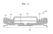
- FIG. 4 is a cross-sectional view of a cap assembly 150' according to another embodiment of the present invention.
- the cap assembly 150' includes a sub-disc 161, a vent 162, a cap-down 163, and an insulator 164.
- the sub-disc 161 is disposed to correspond to an end 120a of the centre pin 120.
- the vent 162 is welded to the sub-disc 161. In this regard, if the vent 162 is deformed by gas pressure, the sub-disc 161 is detached from the vent 162 so that current is interrupted.
- the cap-down 163 maintains the structure of the sub-disc 161 and the vent 162.
- the insulator 164 is disposed between the cap-down 163 and the vent 162 to function as an insulator.
- the cylindrical lithium secondary battery will be described with reference to the cap assembly 150 illustrated in FIGS. 1 to 3 , but is not limited thereto.
- the function and operation of the centre pin 120 in FIGS. 1 to 3 may be applied to the cap assembly 150' of FIG. 4 in the same manner.
- the cylindrical can 140 has a beading part 143 located on the lower portion of the cap assembly 150 and recessed towards the interior of the cylindrical can 140, and a crimping part 144 formed on the upper portion of the cap assembly 150 and bent towards the interior of the cylindrical can 140.
- the beading part 143 and the crimping part 144 firmly fix and support the cap assembly 150 to the cylindrical can 140, prevent displacement of the cap assembly 150, and leaking out of an electrolyte.
- the cylindrical can 140 has an electrolyte (not shown) injected therein to enable lithium ions, which are generated by an electrochemical reaction from the negative electrode plate 111 and the positive electrode plate 112 during the charging/discharging, to move through the elecrolyte.
- the electrolyte may be a non-aqueous organic electrolyte, which is a mixture of a lithium salt and a high-purity organic solvent.
- the electrolyte may be a polymer using a high-molecular electrolyte, but the type of electrolyte is not limited thereto.
- the centre pin 120 may be located at the centre of the electrode assembly 110.
- the centre pin 120 may have a hollow inside in the lengthwise direction.
- the structure of the centre pin 120 is not limited thereto, and the centre pin 120 may also have a filled inside.
- secondary batteries may explode due to various reasons. For example, if the cylindrical lithium secondary battery is overcharged, the electrolyte is evaporated from the upper portion of the electrode assembly 110 so that it increases the resistance gradually. Then, the electrode assembly 110 starts to deform from the central region thereof so that lithium is precipitated. In addition, as the resistance of the upper portion of the electrode assembly 110 increases, heat is generated to increase the temperature of the cylindrical lithium secondary battery.
- the internal pressure is rapidly increased by cyclohexyl benzene (CHB) and biphenyl (BP) (electrolyte additives) that are generally decomposed to generate gas when the battery is overcharged, and thus the cylindrical lithium secondary battery may explode.
- CHB cyclohexyl benzene
- BP biphenyl
- electrolyte additives electrolyze additives
- the centre pin 120 may penetrate the cap assembly 150 to protrude from the cap assembly 150. If the centre pin 120 protrudes from the cap assembly 150 due to the explosion of the cylindrical lithium secondary battery, the cylindrical lithium secondary battery may have a serious safety problem.
- At least one end of the centre pin 120 may be designed to be deformed by the collision with the inner surface of the can 140 or the cap assembly 150 to buffer the impact power of the centre pin 120, thereby preventing the protrusion of the centre pin 120.
- FIG. 5 is a partial cross-sectional view of the lithium secondary battery according to an embodiment of the present invention illustrating a centre pin 120 that is deformed by the collision with the positive electrode cap 155 caused by the explosion of the lithium secondary battery.
- the centre pin 120 When the centre pin 120 is displaced by the explosion, the centre pin 120 collides with the safety vent 152, and penetrates the safety vent 152 to deform the safety vent 152. If the safety vent 152 is deformed by the internal pressure caused by, for example, gas, the circuit board 153 disposed at one side of the safety vent 152 is damaged to interrupt the current. As such, the wiring pattern disposed on the circuit board 153 is cut off to interrupt the current flow, thereby functioning as a safety device.
- the safety vent 152 When the safety vent 152 is deformed by the collision of the end of the centre pin 120 with the safety vent 152, the mechanical force of the centre pin 120 in addition to the increased internal pressure directly apply to the safety vent 152, and thus the safety vent 152 and the circuit board 153 may be seriously deformed, thereby improving safety. Then, the centre pin 120 collides with the positive electrode cap 155 of the cap assembly 150. In this regard, the one end of the centre pin 120 is easily deformed as shown in FIG. 5 to absorb the impact power when the centre pin 120 collides with the positive electrode cap 155, thereby preventing the centre pin 120 from protruding.
- the collision between the centre pin 120 and the positive electrode cap 155 will only be described for the collision between the centre pin 120 and other elements.
- the collision between the centre pin 120 and other elements due to the explosion of the centre pin 120 is not limited thereto.
- the centre pin 120 may also collide with a bottom surface 142 of the can 140 as well as the positive electrode cap 155.
- the end 120a of the centre pin 120 may have various structures to be deformed by the collision to buffer the impact power.
- one end of the centre pin 120 may have at least one selected from the group consisting of a notched end n, a slit end g, a holed end h, or any combination thereof.
- the centre pin 120 having a notched end n will be described with reference to FIGS. 6A to 6E , 7A to 7E , and 8
- the centre pin 120 having a slit end g will be described with reference to FIGS. 9A to 9E, 10 , 11A to 11E , and 12
- the centre pin 120 having a holed end h will be described with reference to FIGS. 13A to 13C .
- the centre pin 120 having the combination of the notched end n and the slit end g will be described with reference to FIGS. 14A to 14C
- the centre pin 120 having the combination of the slit end g and the holed end h will be described with reference to FIGS. 15A to 15C
- the centre pin 120 having the combination of the notched end n, the slit end g, and the holed end h will be described with reference to FIG. 16 .
- the centre pin 120 described above has a hollow inside in the lengthwise direction.
- the structure of the centre pin 120 is not limited thereto, and the centre pin 120 may have a filled inside.
- the end of the centre pin 120 is not limited to the notched end n, the slit end g, the holed end h, and any combination thereof, and thus, the end of the centre pin 120 may have various structures in order to buffer the impact power to prevent the centre pin 120 from protruding.
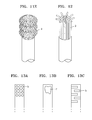
- FIGS. 6A to 6E are schematic front views of centre pins 120 having a notched end n.
- FIGS. 7A to 7E are cross-sectional views of ends of the centre pins of FIGS. 6A to 6E having a slope due to the reduced thickness of the end along the lengthwise direction of the centre pin.
- FIG. 8 is a schematic cross-sectional view taken along line VIII-VIII' of FIG. 6 .
- the centre pin 120 may have at least one notched end n along the lengthwise direction of the centre pin 120.
- the shape of the notched end n is not limited thereto.
- the notched end n of the centre pin 120 may have slanted notches or zigzagged notches.
- the diameter of the centre pin 120 is constant.
- the end of the centre pin 120 may be sharpened such that the centre pin 120 has a slope due to the reduced thickness of the end of the centrepin120 along the lengthwise direction of the centre pin120.
- the end of the centre pin 120 has a beveled edge, as shown in Figures 7A and 7B .
- the end of the centre pin 120 has a slope that easily slides radially outward or inward when the end collides with the positive electrode cap 155.
- the end of the centre pin 120 is easily fractured and deformed radially outward when colliding with the positive electrode cap 155.
- the shape of the end of the centre pin 120 is not limited thereto.
- the end of the centre pin 120 may also have a cross-section without a slope.
- the notched end n has notches in the outer surface of the centre pin 120.
- the notched end n is not limited thereto.
- the notched end n may also have notches in the outer surface or inner surface of the centre pin 120 so as to be easily fractured and deformed when colliding with the positive electrode cap 155 to buffer the impact power applied to the centre pin 120.
- the degree of deformation of the centre pin 120 when colliding with positive electrode cap 155 may be controlled by regulating the depth of the notches of the notched end n.
- the bottom of the notch of the notched end n may be sharp or flat.
- FIG. 6B illustrates the end of the centre pin 120 that is formed such that the diameter of the centre pin 120 increases along the lengthwise direction of the centre pin 120.
- the end of the centre pin 120 may be fractured and deformed radially outward when the centre pin 120 collides with the positive electrode cap 155.
- FIG. 7B is a cross-sectional view of the centre pin 120 shown in FIG. 6B . If the notched end n of the centre pin 120 has a slope that easily slides radially outward when the notched end n collides with the positive electrode cap 155, as shown in FIG. 7B , the notched end n of the centre pin 120 may be more easily deformed radially outward when colliding with the positive electrode cap 155.
- FIG. 6C illustrates the notched end n of the centre pin 120 that has a curved shape along the lengthwise direction of the centre pin 120.
- the curved shaped of the notched end n is not limited to the shape shown in FIG. 6C in which the centre of the notched end n is swollen, and thus the notched end n may have various curved shapes.
- FIG. 7C is a cross-sectional view of the centre pin 120 shown in FIG. 6C .
- the impact power is scattered in the circumferential direction of the centre pin 120 in addition to the lengthwise direction of the centre pin 120 when the centre pin 120 collides with the positive electrode cap 155, and thus buffered.
- FIG. 6D illustrates the notched end n of the centre pin 120 that has a tapered shape along the lengthwise direction of the centre pin 120 so that the centre pin 120 is easily fractured and deformed to buffer the impact power when colliding with the positive electrode cap 155.
- the notched end n of the centre pin 120 has a tapered shape in which the diameter of the centre pin 120 decreases along the lengthwise direction of the centre pin 120
- the notched end n of the centre pin 120 may be fractured and deformed radially inward when the centre pin 120 collides with the positive electrode cap 155.
- FIG. 7D is a cross-sectional view of the centre pin 120 shown in FIG. 6D .
- the notched end n of the centre pin 120 has a slope that easily slides radially inward when the notched end n collides with the positive electrode cap 155, the notched end n may be more easily deformed radially inward when the centre pin 120 collides with the positive electrode cap 155.
- the notched end n of the centre pin 120 may more elastically contact the positive electrode cap 155 during the collision therebetween by bending the notched end n inward.
- FIG. 6E illustrates the notched end n of the centre pin 120 that has a plurality of bends along the lengthwise direction of the centre pin 120.
- FIG. 7E is a cross-sectional view of the centre pin 120 shown in FIG. 6E .
- the centre pin 120 may be elastically fractured and deformed when colliding with the positive electrode cap 155 due to the plurality of bends.
- FIGS. 9A to 9E are schematic front views of centre pins having a slit end g.
- FIG. 10 is a schematic cross-sectional view taken along line X-X' of FIG. 9 .
- FIGS. 11A to 11E are schematic perspective views of FIGS. 9A to 9E , respectively.
- FIG. 12 is a schematic perspective view of the slit end g, at least one projection of which is curved radially outward.
- the centre pin 120 may have a slit end g that is split with gaps along the lengthwise direction of the centre pin 120, to form a plurality of projections separated by gaps.
- the centre pin 120 may have a slanted slit end g that is split by slits to form a plurality of projections with gaps.
- the slit end g of FIG. 9A may have a slope at the tip thereof.
- FIG. 10 illustrates the cross-section of the centre pin 120 having the slit end g.
- FIG. 9B illustrates the slit end g of the centre pin 120 that has a plurality of slits along the lengthwise direction of the centre pin 120.
- the slit end g of FIG. 9B may have a slope facing the centre at the tip thereof as shown in FIG. 7B .
- the tip of at least one portion of the slit end g may be formed radially outward so that the slit end g is easily deformed when the centre pin 120 collides with the positive electrode cap 155 to buffer the impact power.
- the slit end g is deformed radially outward when the centre pin 120 collides with the positive electrode cap 155.
- FIG. 9C illustrates the slit end g of the centre pin 120 that has a curved shape with a plurality of slits formed along the lengthwise direction of the centre pin 120 .
- the slit end g of the centre pin 120 shown in FIG. 9C may have a curved shape as shown in FIG. 7C . Due to the curved shape of the slit end g of the centre pin 120 as described above, the impact power is scattered in the circumferential direction of the centre pin 120 in addition to the lengthwise direction of the centre pin 120 when the centre pin 120 collides with the positive electrode cap 155, and thus buffered.
- FIG. 9D illustrates the centre pin 120 that has a slit end g that is split along the lengthwise direction of the centre pin 120 with slits.
- the slit end g of the centre pin 120 of FIG. 9D has a slope that easily slides radially inward when the slit end g collides with the positive electrode cap 155 as shown in FIG. 7D .
- the slit end g may be bent inward so that the slit end g may more elastically contact the positive electrode cap 155 during the collision therebetween.
- At least one projection of the slit end g may be formed radially inward so that the slit end g is easily deformed to buffer the impact power when the centre pin 120 collides with the positive electrode cap 155.
- the slit end g may be deformed radially inward when the centre pin 120 collides with the positive electrode cap 155.
- FIG. 9E illustrates the slit end g of the centre pin 120 that has a plurality of projections along the lengthwise direction of the centre pin 120.
- the slit end g of the centre pin 120 shown in FIG. 9E may have a plurality of bends along the lengthwise direction of the centre pin 120, as shown in FIG. 7E .
- the centre pin 120 may be elastically fractured and deformed when colliding with the positive electrode cap 155 due to the plurality of bends.
- the shape of the slit end g of the centre pin 120 is not limited thereto.
- the tip of the slit end g may be bent radially outward or inward.
- FIG. 12 illustrates the slit end g of the centre pin 120 that has a plurality of slits along the lengthwise direction of the centre pin 120 such that some projections of the slit end g are bent radially inward, and the other projections of the slit end g are bent radially outward.
- the centre pin 120 collides with the positive electrode cap 155 due to the explosion of the cylindrical lithium secondary battery, the centre pin 120 may be easily fractured or deformed by modifying the direction and shape of the slit end g.
- the centre pin 120 may be designed not to penetrate and protrude the positive electrode cap 155.
- FIGS. 13A to 13C are front views of centre pins having a holed end h.
- at least one end of the centre pin 120 may have a holed end h with holes so that the centre pin 120 is easily fractured and deformed to buffer the impact power when the centre pin 120 collides with the positive electrode cap 155.
- FIG. 13A illustrates a centre pin 120 having a holed end h with a predetermined pattern of a plurality of holes.
- FIG. 13B illustrates a centre pin 120 having a holed end h with a single hole such that the centre pin 120 is easily fractured.
- FIG. 13C illustrates a centre pin 120 having a holed end h with holes that are alternately formed.
- the holed end h of the centre pin 120 may have a tapered shape so that the centre pin 120 is easily fractured and deformed to buffer the impact power when colliding with the positive electrode cap 155.
- the holed end h of the centre pin 120 may be formed such that the diameter of the centre pin 120 increases along the lengthwise direction of the centre pin 120.
- the holed end h of the centre pin 120 may have a curved shape along the lengthwise direction of the centre pin 120 so that the centre pin 120 is easily fractured and deformed to buffer the impact power when colliding with the positive electrode cap 155.
- the holed end h of the centre pin 120 may have a slope due to the reduced thickness of the end of the ceter pin 120 along the lengthwise direction.
- FIGS. 14A to 14C are front views of centre pins having a combination of a notched end n and a slit end g.
- the centre pin 120 may have a combination of the notched end n and the slit end g so as to be easily fractured and deformed to buffer the impact power applied to the centre pin 120 and prevent the centre pin 120 from protruding when colliding with the positive electrode cap 155.
- FIG. 14A illustrates a combination of the notched end n and the slit end g that is formed straight such that the diameter of the centre pin 120 is constant.
- FIG. 14B illustrates a centre pin 120 having a slit end g, the tip of which is bent radially inward, and a notched end n disposed at the other end of the tip of the slit end g.
- FIG. 14C illustrates a centre pin 120 having a slit end g, the tip of which is bent radially outward, and a notched end n disposed at the other end of the tip of the slit end g.
- FIGS. 15A to 15C are front views of centre pins having a combination of a slit end g and a holed end h.
- the centre pin 120 may have a combination of the slit end g and the holed end h so as to be easily fractured and deformed to buffer the impact power applied to the centre pin 120 and prevent the centre pin 120 from protruding when colliding with the positive electrode cap 155.
- FIG. 15A illustrates a combination of the slit end g and the holed end h that is formed straight such that the diameter of the centre pin 120 is constant.
- FIG. 15B illustrates the centre pin 120 having a slit end g, the tip of which is bent radially inward, and a holed end h disposed at the other end of the tip of the slit end g.
- FIG. 15C illustrates the centre pin 120 having a slit end g, the tip of which is bent radially outward, and a holed end h disposed at the other end of the tip of the slit end g.
- FIG. 16 is a front view of the centre pin 120 having a combination of a notched end n, a slit end g, and a holed end h. Due to the notched end n, the slit end g, and the holed end h of the centre pin 120, the centre pin 120 may be easily fractured and deformed when the centre pin 120 collides with the positive electrode cap 155 due to the explosion of the cylindrical lithium secondary battery.
- the centre pin 120 may be designed in various ways to not penetrate and protrude from the positive electrode cap 155.
Landscapes
- Chemical & Material Sciences (AREA)
- Chemical Kinetics & Catalysis (AREA)
- Electrochemistry (AREA)
- General Chemical & Material Sciences (AREA)
- Engineering & Computer Science (AREA)
- Manufacturing & Machinery (AREA)
- Materials Engineering (AREA)
- Sealing Battery Cases Or Jackets (AREA)
- Secondary Cells (AREA)
- Connection Of Batteries Or Terminals (AREA)
Abstract
Description
- The present invention relates to a lithium secondary battery, and more particularly, to a cylindrical lithium secondary battery including a functional centre pin.
- In general, cylindrical lithium secondary batteries include a cylindrical electrode assembly combined with a centre pin, a cylindrical can containing the electrode assembly, an electrolyte that is injected into the can to allow lithium ions to move, and a cap assembly connected to one side of the can to prevent the electrolyte from leaking out and the electrode assembly from being displaced. Such cylindrical lithium secondary batteries have a capacity ranging from 2000 to 4000 mA, and thus, are applied to mobile devices with large power consumption such as notebook computers, digital cameras, and camcorders. For example, a plurality of cylindrical lithium secondary batteries are connected to each other in series or in parallel and assembled with a protective circuit to form a hard pack having a predetermined shape to be used as a power source for mobile devices. In addition, a cylindrical lithium secondary battery may be manufactured according to the following process. A negative electrode plate coated with a negative electrode active material, a separator, and a positive electrode plate coated with a positive electrode active material are stacked, where one end of the stack is bound to a rod-shaped winding axis, and the stack is wound to have a cylindrical shape. Then, a centre pin is assembled with the electrode assembly, and the electrode assembly is inserted into the cylindrical can. Then, an electrolyte is injected into the cylindrical can, and a cap assembly is coupled to the upper portion of the cylindrical can to manufacture the cylindrical lithium secondary battery. Meanwhile, such cylindrical lithium secondary batteries include a safety vent that is deformed when the internal pressure increases due to an overcharge, and a circuit board that breaks according to the deformation of the safety vent to interrupt current in order to prevent an explosion and an outbreak of a fire caused by the overcharge. In general, the safety vent and the circuit board constitute a current interrupt device (CID), which is an element of a cap assembly.
- One or more embodiments of the present invention include a cylindrical lithium secondary battery having excellent safety by preventing a centre pin from protruding when the cylindrical lithium secondary battery explodes due to an increase in internal pressure.
- Accordingly, the present invention provides a lithium secondary battery comprising an electrode assembly having a centre pin at the centre thereof, a can containing the electrode assembly and a cap assembly coupled to the can, wherein an end portion of the centre pin is configured such that if the centre pin collides with an inner surface of the can or the cap assembly, the end portion will deform to buffer the impact power, and prevent the centre pin from penetrating the can or cap assembly.
- More specifically, the centre pin is disposed along a longitudinal axis of the can and the cap assembly is coupled to a top side of the can.
- Preferably, the can is cylindrical. However, the invention is not limited to this and the can may have other shapes.
- The centre pin may be hollow at the end portion, and may further be hollow along its entire length. The end of the centre pin may have beveled edges. This assists the end portion to deform as the beveled edges are deflected on impact with the inner surface of the can or the cap assembly.
- The end portion of the centre pin may have notches along the lengthwise direction of the centre pin.
- The end portion of the centre pin may include holes.
- The end portion of the centre pin may be tapered. The diameter of the end portion may increase or decrease towards the end of the centre pin.
- The end portion of the centre pin may be split along the lengthwise direction of the centre pin to form a plurality of projections separated by gaps. At least one of the projections may be bent radially outward and/or at least one of the projections may be bent radially inward. The thickness of at least one of the projections may decrease towards its end.
- The end portion may have a bend along the lengthwise direction of the centre pin. Due to the modified structures described above, at least one end of the centre pin is easily deformed when the centre pin collides with the inner surface of the can or the cap assembly so that the impact power may be buffered.
- In a cylindrical lithium secondary battery according to embodiments of the present invention, the centre pin is fractured and deformed when colliding with the cap assembly and/or the inner surface of the can during the explosion of the cylindrical lithium secondary battery so as to prevent the centre pin from protruding and improve safety of the cylindrical lithium secondary battery.
- Furthermore, since the centre pin has excellent safety using a notched end or slit end without using additional structure, the manufacturing costs for the cylindrical lithium secondary battery may be reduced.
- These and/or other aspects will become apparent and more readily appreciated from the following description of the embodiments, taken in conjunction with the accompanying drawings of which:
-
FIG. 1 is a schematic perspective view of a cylindrical lithium secondary battery according to an embodiment of the present invention; -
FIG. 2 is a schematic cross-sectional view taken along line II-II' ofFIG. 1 ; -
FIG. 3 is a schematic exploded perspective view of the lithium secondary battery shown inFIG. 1 ; -
FIG. 4 is a cross-sectional view of a cap assembly according to another embodiment of the present invention; -
FIG. 5 is a partial cross-sectional view of a cylindrical lithium secondary battery according to an embodiment of the present invention illustrating a centre pin that is deformed by the collision with a positive electrode cap due to the explosion of the lithium secondary battery; -
FIGS. 6A to 6E are schematic front views of centre pins having a notched end; -
FIGS. 7A to 7E are cross-sectional views of ends of the centre pins ofFIGS. 6A to 6E having a slope due to the reduced thickness of the end along the lengthwise direction of the centre pin; -
FIG. 8 is a schematic cross-sectional view taken along line VIII-VIII' ofFIG. 6A ; -
FIGS. 9A to 9E are schematic front views of centre pins having a slit end; -
FIG. 10 is a schematic cross-sectional view taken along line X-X' ofFIG. 9 ; -
FIGS. 11A to 11E are schematic perspective views ofFIGS. 9A to 9E , respectively; -
FIG. 12 is a schematic perspective view of the split end, at least one projection of which is bent radially outward; -
FIGS. 13A to 13C are front views of centre pins having a holed end; -
FIGS. 14A to 14C are front views of centre pins having a combination of a notched end and a slit end; -
FIGS. 15A to 15C are front views of centre pins having a combination of a slit end and a holed end; and -
FIG. 16 is a front view of a centre pin having a combination of a notched end, a slit end, and a holed end. - Reference will now be made in detail to embodiments, examples of which are illustrated in the accompanying drawings, wherein like reference numerals refer to the like elements throughout. In this regard, the present embodiments may have different forms and should not be construed as being limited to the descriptions set forth herein. Accordingly, the embodiments are merely described below, by referring to the figures, to explain aspects of the present description.
- Referring to
FIGS. 1 to 3 , a cylindrical lithiumsecondary battery 100 will be described.FIG. 1 is a schematic perspective view of a cylindrical lithiumsecondary battery 100 according to an embodiment of the present invention.FIG. 2 is a schematic cross-sectional view taken along line II-II' ofFIG. 1 .FIG. 3 is a schematic exploded perspective view of the lithiumsecondary battery 100 shown inFIG. 1 . - Referring to
FIGS. 1 to 3 , the cylindrical lithiumsecondary battery 100 includes anelectrode assembly 110, acentre pin 120, acylindrical can 140, and acap assembly 150. Theelectrode assembly 110 includes anegative electrode plate 111, apositive electrode plate 112, and aseparator 113. In this regard, thenegative electrode plate 111 is coated with a negative electrode active material, such as graphite. Thepositive electrode plate 112 is coated with a positive electrode active material such as lithium cobalt oxide (LiCoO2). In this regard, theseparator 113 is disposed between thenegative electrode plate 111 and the positive electrode plate to prevent a short circuit and allow only lithium ions to move therethrough. Thenegative electrode plate 111, thepositive electrode plate 112, and theseparator 113 are wound approximately into the shape of a cylinder and are contained in thecylindrical can 140. Thenegative electrode plate 111 may be formed of a copper (Cu) foil, thepositive electrode plate 112 may be formed of an aluminum (A1) foil, and theseparator 113 may be formed of polyethylene (PE) or polypropylene (PP). In addition, thenegative electrode plate 111 may be welded to anegative electrode tap 114 that protrudes downward by a predetermined distance, and thepositive electrode plate 112 may be welded to apositive electrode tap 115 that protrudes upward by a predetermined distance, but the reverse is also possible. Thenegative electrode tap 114 may also be formed of nickel (Ni), and thepositive electrode tap 115 may be formed of aluminum (Al). Thecentre pin 120 is coupled approximately at the centre of theelectrode assembly 110 to prevent deformation of theelectrode assembly 110 during charging/discharging of the cylindrical lithiumsecondary battery 100. The materials used to form thenegative electrode plate 111, thepositive electrode plate 112, theseparator 113, thenegative electrode tap 114, and thepositive electrode tap 115 are not limited thereto, and any materials that are commonly used in the art may be used. - Meanwhile, the cylindrical can 140 may be formed of steel, stainless steel, aluminum, or an equivalent thereof, but the material thereof is not limited herein. Referring to
FIG. 3 , thecap assembly 150 includes agasket 151, asafety vent 152, acircuit board 153, a positive temperature coefficient (PTC) 154, and apositive electrode cap 155. Thecap assembly 150 may be disposed at one side of thecylindrical can 140. Thegasket 151 having a ring shape is disposed at the one side of thecylindrical can 140. In this regard, the insulatinggasket 151 may be coupled to thesafety vent 152 that is conductive and connected to thepositive electrode tap 115. Here, thesafety vent 152 deforms or fractures, when the internal pressure of thecan 140 increases to break thecircuit board 153, or exhaust gas out of the cylindrical lithiumsecondary battery 100. Thecircuit board 153 is located at one side of thesafety vent 152 to be damaged or broken, when thesafety vent 152 deforms, thereby interrupting current. ThePTC 154 is located on top of thecircuit board 153 to interrupt the current in the case of overcurrent. Thepositive electrode cap 155 is located at one side of thePTC 154 to apply positive electrode voltage (or negative electrode voltage) to the external device. In addition, thepositive electrode cap 155 may include a plurality of through-holes 155a for easy gas exhaustion. Thesafety vent 152, thecircuit board 153, thePTC 154, and thepositive electrode cap 155 are located inside of the insulatinggasket 151 to prevent them from being directly short-circuited to thecylindrical can 140. Also, thecircuit board 153 has awiring pattern 153a on the surface thereof, which is cut off when thecircuit board 153 is damaged or broken. - However, the structure of the
cap assembly 150 is not limited thereto.FIG. 4 is a cross-sectional view of a cap assembly 150' according to another embodiment of the present invention. The cap assembly 150' includes a sub-disc 161, avent 162, a cap-down 163, and aninsulator 164. Here, the sub-disc 161 is disposed to correspond to anend 120a of thecentre pin 120. Thevent 162 is welded to the sub-disc 161. In this regard, if thevent 162 is deformed by gas pressure, the sub-disc 161 is detached from thevent 162 so that current is interrupted. The cap-down 163 maintains the structure of the sub-disc 161 and thevent 162. Theinsulator 164 is disposed between the cap-down 163 and thevent 162 to function as an insulator. Hereinafter, the cylindrical lithium secondary battery will be described with reference to thecap assembly 150 illustrated inFIGS. 1 to 3 , but is not limited thereto. The function and operation of thecentre pin 120 inFIGS. 1 to 3 may be applied to the cap assembly 150' ofFIG. 4 in the same manner. - Referring to
FIG. 2 , the cylindrical can 140 has abeading part 143 located on the lower portion of thecap assembly 150 and recessed towards the interior of thecylindrical can 140, and a crimpingpart 144 formed on the upper portion of thecap assembly 150 and bent towards the interior of thecylindrical can 140. Thebeading part 143 and the crimpingpart 144 firmly fix and support thecap assembly 150 to thecylindrical can 140, prevent displacement of thecap assembly 150, and leaking out of an electrolyte. In addition, the cylindrical can 140 has an electrolyte (not shown) injected therein to enable lithium ions, which are generated by an electrochemical reaction from thenegative electrode plate 111 and thepositive electrode plate 112 during the charging/discharging, to move through the elecrolyte. The electrolyte may be a non-aqueous organic electrolyte, which is a mixture of a lithium salt and a high-purity organic solvent. The electrolyte may be a polymer using a high-molecular electrolyte, but the type of electrolyte is not limited thereto. Thecentre pin 120 may be located at the centre of theelectrode assembly 110. Thecentre pin 120 may have a hollow inside in the lengthwise direction. However, the structure of thecentre pin 120 is not limited thereto, and thecentre pin 120 may also have a filled inside. Meanwhile, secondary batteries may explode due to various reasons. For example, if the cylindrical lithium secondary battery is overcharged, the electrolyte is evaporated from the upper portion of theelectrode assembly 110 so that it increases the resistance gradually. Then, theelectrode assembly 110 starts to deform from the central region thereof so that lithium is precipitated. In addition, as the resistance of the upper portion of theelectrode assembly 110 increases, heat is generated to increase the temperature of the cylindrical lithium secondary battery. In such a state, the internal pressure is rapidly increased by cyclohexyl benzene (CHB) and biphenyl (BP) (electrolyte additives) that are generally decomposed to generate gas when the battery is overcharged, and thus the cylindrical lithium secondary battery may explode. As such, if the cylindrical lithium secondary battery explodes, thecentre pin 120 may penetrate thecap assembly 150 to protrude from thecap assembly 150. If thecentre pin 120 protrudes from thecap assembly 150 due to the explosion of the cylindrical lithium secondary battery, the cylindrical lithium secondary battery may have a serious safety problem. - Accordingly, at least one end of the
centre pin 120 may be designed to be deformed by the collision with the inner surface of thecan 140 or thecap assembly 150 to buffer the impact power of thecentre pin 120, thereby preventing the protrusion of thecentre pin 120. - Referring to
FIG. 5 , the collision between thecentre pin 120 and thecap assembly 150 will be described.FIG. 5 is a partial cross-sectional view of the lithium secondary battery according to an embodiment of the present invention illustrating acentre pin 120 that is deformed by the collision with thepositive electrode cap 155 caused by the explosion of the lithium secondary battery. - When the
centre pin 120 is displaced by the explosion, thecentre pin 120 collides with thesafety vent 152, and penetrates thesafety vent 152 to deform thesafety vent 152. If thesafety vent 152 is deformed by the internal pressure caused by, for example, gas, thecircuit board 153 disposed at one side of thesafety vent 152 is damaged to interrupt the current. As such, the wiring pattern disposed on thecircuit board 153 is cut off to interrupt the current flow, thereby functioning as a safety device. When thesafety vent 152 is deformed by the collision of the end of thecentre pin 120 with thesafety vent 152, the mechanical force of thecentre pin 120 in addition to the increased internal pressure directly apply to thesafety vent 152, and thus thesafety vent 152 and thecircuit board 153 may be seriously deformed, thereby improving safety. Then, thecentre pin 120 collides with thepositive electrode cap 155 of thecap assembly 150. In this regard, the one end of thecentre pin 120 is easily deformed as shown inFIG. 5 to absorb the impact power when thecentre pin 120 collides with thepositive electrode cap 155, thereby preventing thecentre pin 120 from protruding. - For convenience of explanation, hereinafter the collision between the
centre pin 120 and thepositive electrode cap 155 will only be described for the collision between thecentre pin 120 and other elements. However, the collision between thecentre pin 120 and other elements due to the explosion of thecentre pin 120 is not limited thereto. For example, thecentre pin 120 may also collide with abottom surface 142 of thecan 140 as well as thepositive electrode cap 155. - The
end 120a of thecentre pin 120 may have various structures to be deformed by the collision to buffer the impact power. For example, one end of thecentre pin 120 may have at least one selected from the group consisting of a notched end n, a slit end g, a holed end h, or any combination thereof. Thecentre pin 120 having a notched end n will be described with reference toFIGS. 6A to 6E ,7A to 7E , and8 , thecentre pin 120 having a slit end g will be described with reference toFIGS. 9A to 9E, 10 ,11A to 11E , and12 , and thecentre pin 120 having a holed end h will be described with reference toFIGS. 13A to 13C . Thecentre pin 120 having the combination of the notched end n and the slit end g will be described with reference toFIGS. 14A to 14C , thecentre pin 120 having the combination of the slit end g and the holed end h will be described with reference toFIGS. 15A to 15C , and thecentre pin 120 having the combination of the notched end n, the slit end g, and the holed end h will be described with reference toFIG. 16 . In this regard, thecentre pin 120 described above has a hollow inside in the lengthwise direction. However, the structure of thecentre pin 120 is not limited thereto, and thecentre pin 120 may have a filled inside. In this regard, the end of thecentre pin 120 is not limited to the notched end n, the slit end g, the holed end h, and any combination thereof, and thus, the end of thecentre pin 120 may have various structures in order to buffer the impact power to prevent thecentre pin 120 from protruding. - First, the
centre pin 120 having the notched end n will be described with reference toFIGS. 6A to 6E ,7A to 7E , and8 .FIGS. 6A to 6E are schematic front views of centre pins 120 having a notched end n.FIGS. 7A to 7E are cross-sectional views of ends of the centre pins ofFIGS. 6A to 6E having a slope due to the reduced thickness of the end along the lengthwise direction of the centre pin.FIG. 8 is a schematic cross-sectional view taken along line VIII-VIII' ofFIG. 6 . - As shown in
FIG. 6A , thecentre pin 120 may have at least one notched end n along the lengthwise direction of thecentre pin 120. Even though the notched end n is formed in the lengthwise direction of thecentre pin 120, the shape of the notched end n is not limited thereto. For example, the notched end n of thecentre pin 120 may have slanted notches or zigzagged notches. In this regard, the diameter of thecentre pin 120 is constant. Here, the end of thecentre pin 120 may be sharpened such that thecentre pin 120 has a slope due to the reduced thickness of the end of the centrepin120 along the lengthwise direction of the centre pin120. Thus, the end of thecentre pin 120 has a beveled edge, as shown inFigures 7A and 7B . In this regard, the end of thecentre pin 120 has a slope that easily slides radially outward or inward when the end collides with thepositive electrode cap 155. Thus, the end of thecentre pin 120 is easily fractured and deformed radially outward when colliding with thepositive electrode cap 155. - However, the shape of the end of the
centre pin 120 is not limited thereto. The end of thecentre pin 120 may also have a cross-section without a slope. Referring toFIG. 8 , the notched end n has notches in the outer surface of thecentre pin 120. However, the notched end n is not limited thereto. The notched end n may also have notches in the outer surface or inner surface of thecentre pin 120 so as to be easily fractured and deformed when colliding with thepositive electrode cap 155 to buffer the impact power applied to thecentre pin 120. The degree of deformation of thecentre pin 120 when colliding withpositive electrode cap 155 may be controlled by regulating the depth of the notches of the notched end n. In addition, the bottom of the notch of the notched end n may be sharp or flat. - As a modified example of
FIG. 6A, FIG. 6B illustrates the end of thecentre pin 120 that is formed such that the diameter of thecentre pin 120 increases along the lengthwise direction of thecentre pin 120. As such, when the diameter of thecentre pin 120 increases along the lengthwise direction of thecentre pin 120, the end of thecentre pin 120 may be fractured and deformed radially outward when thecentre pin 120 collides with thepositive electrode cap 155. -
FIG. 7B is a cross-sectional view of thecentre pin 120 shown inFIG. 6B . If the notched end n of thecentre pin 120 has a slope that easily slides radially outward when the notched end n collides with thepositive electrode cap 155, as shown inFIG. 7B , the notched end n of thecentre pin 120 may be more easily deformed radially outward when colliding with thepositive electrode cap 155. - As a modified example of
FIG. 6A, FIG. 6C illustrates the notched end n of thecentre pin 120 that has a curved shape along the lengthwise direction of thecentre pin 120. In this regard, the curved shaped of the notched end n is not limited to the shape shown inFIG. 6C in which the centre of the notched end n is swollen, and thus the notched end n may have various curved shapes.FIG. 7C is a cross-sectional view of thecentre pin 120 shown inFIG. 6C . Due to the curved shape of the notched end n of thecentre pin 120 as described above, the impact power is scattered in the circumferential direction of thecentre pin 120 in addition to the lengthwise direction of thecentre pin 120 when thecentre pin 120 collides with thepositive electrode cap 155, and thus buffered. - As a modified example of
FIG. 6A, FIG. 6D illustrates the notched end n of thecentre pin 120 that has a tapered shape along the lengthwise direction of thecentre pin 120 so that thecentre pin 120 is easily fractured and deformed to buffer the impact power when colliding with thepositive electrode cap 155. As described above, when the notched end n of thecentre pin 120 has a tapered shape in which the diameter of thecentre pin 120 decreases along the lengthwise direction of thecentre pin 120, the notched end n of thecentre pin 120 may be fractured and deformed radially inward when thecentre pin 120 collides with thepositive electrode cap 155.FIG. 7D is a cross-sectional view of thecentre pin 120 shown inFIG. 6D . If the notched end n of thecentre pin 120 has a slope that easily slides radially inward when the notched end n collides with thepositive electrode cap 155, the notched end n may be more easily deformed radially inward when thecentre pin 120 collides with thepositive electrode cap 155. Alternatively, the notched end n of thecentre pin 120 may more elastically contact thepositive electrode cap 155 during the collision therebetween by bending the notched end n inward. - As a modified example of
FIG. 6A, FIG. 6E illustrates the notched end n of thecentre pin 120 that has a plurality of bends along the lengthwise direction of thecentre pin 120.FIG. 7E is a cross-sectional view of thecentre pin 120 shown inFIG. 6E . Thecentre pin 120 may be elastically fractured and deformed when colliding with thepositive electrode cap 155 due to the plurality of bends. - Hereinafter, the
centre pin 120 having the slit end g will be described with reference toFIGS. 9A to 9E, 10 ,11A to 11E , and12 .FIGS. 9A to 9E are schematic front views of centre pins having a slit end g.FIG. 10 is a schematic cross-sectional view taken along line X-X' ofFIG. 9 .FIGS. 11A to 11E are schematic perspective views ofFIGS. 9A to 9E , respectively.FIG. 12 is a schematic perspective view of the slit end g, at least one projection of which is curved radially outward. - The
centre pin 120 may have a slit end g that is split with gaps along the lengthwise direction of thecentre pin 120, to form a plurality of projections separated by gaps. In this regard, thecentre pin 120 may have a slanted slit end g that is split by slits to form a plurality of projections with gaps. In this regard, the slit end g ofFIG. 9A may have a slope at the tip thereof.FIG. 10 illustrates the cross-section of thecentre pin 120 having the slit end g. - As a modified example of
FIG. 9A, FIG. 9B illustrates the slit end g of thecentre pin 120 that has a plurality of slits along the lengthwise direction of thecentre pin 120. In this regard, the slit end g ofFIG. 9B may have a slope facing the centre at the tip thereof as shown inFIG. 7B . The tip of at least one portion of the slit end g may be formed radially outward so that the slit end g is easily deformed when thecentre pin 120 collides with thepositive electrode cap 155 to buffer the impact power. Here, the slit end g is deformed radially outward when thecentre pin 120 collides with thepositive electrode cap 155. - As a modified example of
FIG. 9A, FIG. 9C illustrates the slit end g of thecentre pin 120 that has a curved shape with a plurality of slits formed along the lengthwise direction of thecentre pin 120 . In this regard, the slit end g of thecentre pin 120 shown inFIG. 9C may have a curved shape as shown inFIG. 7C . Due to the curved shape of the slit end g of thecentre pin 120 as described above, the impact power is scattered in the circumferential direction of thecentre pin 120 in addition to the lengthwise direction of thecentre pin 120 when thecentre pin 120 collides with thepositive electrode cap 155, and thus buffered. - As a modified example of
FIG. 9A, FIG. 9D illustrates thecentre pin 120 that has a slit end g that is split along the lengthwise direction of thecentre pin 120 with slits. Here, the slit end g of thecentre pin 120 ofFIG. 9D has a slope that easily slides radially inward when the slit end g collides with thepositive electrode cap 155 as shown inFIG. 7D . Alternatively, the slit end g may be bent inward so that the slit end g may more elastically contact thepositive electrode cap 155 during the collision therebetween. At least one projection of the slit end g may be formed radially inward so that the slit end g is easily deformed to buffer the impact power when thecentre pin 120 collides with thepositive electrode cap 155. Here, the slit end g may be deformed radially inward when thecentre pin 120 collides with thepositive electrode cap 155. - As a modified example of
FIG. 9A, FIG. 9E illustrates the slit end g of thecentre pin 120 that has a plurality of projections along the lengthwise direction of thecentre pin 120. In this regard, the slit end g of thecentre pin 120 shown inFIG. 9E may have a plurality of bends along the lengthwise direction of thecentre pin 120, as shown inFIG. 7E . Thecentre pin 120 may be elastically fractured and deformed when colliding with thepositive electrode cap 155 due to the plurality of bends. - The shape of the slit end g of the
centre pin 120 is not limited thereto. For example, the tip of the slit end g may be bent radially outward or inward. - As a modified example of
FIG. 9A ,FIG. 12 illustrates the slit end g of thecentre pin 120 that has a plurality of slits along the lengthwise direction of thecentre pin 120 such that some projections of the slit end g are bent radially inward, and the other projections of the slit end g are bent radially outward. When thecentre pin 120 collides with thepositive electrode cap 155 due to the explosion of the cylindrical lithium secondary battery, thecentre pin 120 may be easily fractured or deformed by modifying the direction and shape of the slit end g. Thecentre pin 120 may be designed not to penetrate and protrude thepositive electrode cap 155. - The
centre pin 120 having the holed end h will be described with reference toFIGS. 13A to 13C. FIGS. 13A to 13C are front views of centre pins having a holed end h. Referring toFIGS. 13A to 13C , at least one end of thecentre pin 120 may have a holed end h with holes so that thecentre pin 120 is easily fractured and deformed to buffer the impact power when thecentre pin 120 collides with thepositive electrode cap 155.FIG. 13A illustrates acentre pin 120 having a holed end h with a predetermined pattern of a plurality of holes.FIG. 13B illustrates acentre pin 120 having a holed end h with a single hole such that thecentre pin 120 is easily fractured.FIG. 13C illustrates acentre pin 120 having a holed end h with holes that are alternately formed. - Although not shown herein, the holed end h of the
centre pin 120 may have a tapered shape so that thecentre pin 120 is easily fractured and deformed to buffer the impact power when colliding with thepositive electrode cap 155. Alternatively, the holed end h of thecentre pin 120 may be formed such that the diameter of thecentre pin 120 increases along the lengthwise direction of thecentre pin 120. - Alternatively, the holed end h of the
centre pin 120 may have a curved shape along the lengthwise direction of thecentre pin 120 so that thecentre pin 120 is easily fractured and deformed to buffer the impact power when colliding with thepositive electrode cap 155. Also, the holed end h of thecentre pin 120 may have a slope due to the reduced thickness of the end of theceter pin 120 along the lengthwise direction. - Referring to
FIGS. 14A to 14C , acentre pin 120 having a combination of a notched end n and a slit end g will be described.FIGS. 14A to 14C are front views of centre pins having a combination of a notched end n and a slit end g. Thecentre pin 120 may have a combination of the notched end n and the slit end g so as to be easily fractured and deformed to buffer the impact power applied to thecentre pin 120 and prevent thecentre pin 120 from protruding when colliding with thepositive electrode cap 155. For example,FIG. 14A illustrates a combination of the notched end n and the slit end g that is formed straight such that the diameter of thecentre pin 120 is constant. As a modified example ofFIG. 14A, FIG. 14B illustrates acentre pin 120 having a slit end g, the tip of which is bent radially inward, and a notched end n disposed at the other end of the tip of the slit end g. As a modified example ofFIG. 14A, FIG. 14C illustrates acentre pin 120 having a slit end g, the tip of which is bent radially outward, and a notched end n disposed at the other end of the tip of the slit end g. - Referring to
FIGS. 15A to 15C , acentre pin 120 having a combination of a slit end g and a holed end h will be described.FIGS. 15A to 15C are front views of centre pins having a combination of a slit end g and a holed end h. Thecentre pin 120 may have a combination of the slit end g and the holed end h so as to be easily fractured and deformed to buffer the impact power applied to thecentre pin 120 and prevent thecentre pin 120 from protruding when colliding with thepositive electrode cap 155. For example,FIG. 15A illustrates a combination of the slit end g and the holed end h that is formed straight such that the diameter of thecentre pin 120 is constant. As a modified example ofFIG. 15A, FIG. 15B illustrates thecentre pin 120 having a slit end g, the tip of which is bent radially inward, and a holed end h disposed at the other end of the tip of the slit end g. As a modified example ofFIG. 15A, FIG. 15C illustrates thecentre pin 120 having a slit end g, the tip of which is bent radially outward, and a holed end h disposed at the other end of the tip of the slit end g. - Referring to
FIG. 16 , thecentre pin 120 having the combination of the notched end n, the slit end g, and the holed end h will be described.FIG. 16 is a front view of thecentre pin 120 having a combination of a notched end n, a slit end g, and a holed end h. Due to the notched end n, the slit end g, and the holed end h of thecentre pin 120, thecentre pin 120 may be easily fractured and deformed when thecentre pin 120 collides with thepositive electrode cap 155 due to the explosion of the cylindrical lithium secondary battery. Thecentre pin 120 may be designed in various ways to not penetrate and protrude from thepositive electrode cap 155. - It should be understood that the exemplary embodiments described herein should be considered in a descriptive sense only and not for purposes of limitation. Descriptions of features or aspects within each embodiment should typically be considered as available for other similar features or aspects in other embodiments. While embodiments of the invention have primarily been described in relation to a cylindrical battery, it will be understood by the skilled person that the invention is not limited thereto, and could be applied to other types of battery, such as a prismatic lithium secondary battery.
Claims (15)
- A lithium secondary battery comprising:an electrode assembly (110) having a centre pin (120) at the centre thereof;a can (140) containing the electrode assembly (110); anda cap assembly (150, 150') coupled to the can (140),wherein an end portion (120a) of the centre pin (120) is configured such that if the centre pin (120) collides with an inner surface of the can (140) or the cap assembly (150, 150'), the end portion (120a) will deform to buffer the impact power, and prevent the centre pin (120) from penetrating the can (140) or cap assembly (150, 150').
- The lithium secondary battery of claim 1, wherein the centre pin (120) is disposed along a longitudinal axis of the can (140) and the cap assembly (150, 150') is coupled to a top side of the can.
- The lithium secondary battery of claim 1 or 2, wherein the can (140) is cylindrical.
- The lithium secondary battery of any one of the preceding claims, wherein the centre pin (120) is hollow at the end portion (120a).
- The lithium secondary battery of any one of the preceding claims, wherein the centre pin (120) is hollow along its entire length.
- The lithium secondary battery of claim 4 or 5, wherein the end of the centre pin (120) has beveled edges
- The lithium secondary battery of any one of the preceding claims, wherein the end portion (120a) of the centre pin (120) may has notches (n) along the lengthwise direction of the centre pin (120).
- The lithium secondary battery of any one of the preceding claims, wherein the end portion (120a) of the centre pin (120) includes holes.
- The lithium secondary battery of any one of the preceding claims, wherein the end portion (120a) of the centre pin (120) is tapered.
- The lithium secondary battery of claim 9, wherein the diameter of the end portion (120a) of the centre pin (120) increases towards the end of the centre pin (120).
- The lithium secondary battery of claim 9, wherein the diameter of the end portion (120a) of the centre pin (120) decreases towards the end of the centre pin (120).
- The lithium secondary battery of any one of the preceding claims, wherein the end portion (120a) of the centre pin (120) is split along the lengthwise direction of the centre pin (120) to form a plurality of projections separated by gaps.
- The lithium secondary battery of claim 12, wherein at least one of the projections is bent radially outward and/or at least one of the projections is bent radially inward.
- The lithium secondary battery of any one of claims 12 to 13, wherein the thickness of at least one of the projections decreases towards its end.
- The lithium secondary battery of any one of the preceding claims, wherein the end portion has a bend along the lengthwise direction of the centre pin (120).
Applications Claiming Priority (1)
| Application Number | Priority Date | Filing Date | Title |
|---|---|---|---|
| US25141709P | 2009-10-14 | 2009-10-14 |
Publications (2)
| Publication Number | Publication Date |
|---|---|
| EP2323192A1 true EP2323192A1 (en) | 2011-05-18 |
| EP2323192B1 EP2323192B1 (en) | 2013-01-23 |
Family
ID=43437224
Family Applications (1)
| Application Number | Title | Priority Date | Filing Date |
|---|---|---|---|
| EP10151768A Not-in-force EP2323192B1 (en) | 2009-10-14 | 2010-01-27 | Lithium secondary battery |
Country Status (5)
| Country | Link |
|---|---|
| US (1) | US8574749B2 (en) |
| EP (1) | EP2323192B1 (en) |
| JP (1) | JP5421217B2 (en) |
| KR (1) | KR101127612B1 (en) |
| CN (1) | CN102044696B (en) |
Families Citing this family (17)
| Publication number | Priority date | Publication date | Assignee | Title |
|---|---|---|---|---|
| JP5439448B2 (en) * | 2011-09-12 | 2014-03-12 | 株式会社日立製作所 | Lithium ion secondary battery |
| US9257715B2 (en) | 2012-02-24 | 2016-02-09 | Samsung Sdi Co., Ltd. | Cylindrical secondary battery |
| JP6114543B2 (en) * | 2012-12-14 | 2017-04-12 | 株式会社皆藤製作所 | Winding element conveyor |
| WO2016197568A1 (en) * | 2015-06-12 | 2016-12-15 | 福建南平南孚电池有限公司 | Electrochemical secondary battery having inbuilt charging circuit |
| CN106711520A (en) * | 2015-07-20 | 2017-05-24 | 东莞力朗电池科技有限公司 | Extrusion protection manner for cylindrical lithium ion battery |
| KR102586877B1 (en) * | 2016-04-11 | 2023-10-10 | 삼성에스디아이 주식회사 | Secondary Battery |
| CN108666518B (en) * | 2017-03-31 | 2020-11-06 | 比亚迪股份有限公司 | Battery cover assemblies, single cells, battery modules, power battery packs and electric vehicles |
| CN108666460B (en) * | 2017-03-31 | 2020-11-20 | 比亚迪股份有限公司 | Battery cover assemblies, single cells, battery modules, power battery packs and electric vehicles |
| CN108666459B (en) * | 2017-03-31 | 2020-11-20 | 比亚迪股份有限公司 | Battery cover assemblies, single cells, battery modules, power battery packs and electric vehicles |
| CN108666461B (en) | 2017-03-31 | 2020-11-20 | 比亚迪股份有限公司 | Battery cover assemblies, single cells, battery modules, power battery packs and electric vehicles |
| JP7021506B2 (en) | 2017-11-09 | 2022-02-17 | 三洋電機株式会社 | Secondary battery |
| JP7167427B2 (en) | 2017-11-09 | 2022-11-09 | 三洋電機株式会社 | secondary battery |
| JP7028748B2 (en) * | 2018-10-18 | 2022-03-02 | 本田技研工業株式会社 | Storage cell and manufacturing method of storage cell |
| KR102906872B1 (en) * | 2020-03-17 | 2026-01-02 | 삼성에스디아이 주식회사 | secondary battery |
| KR20220019477A (en) * | 2020-08-10 | 2022-02-17 | 삼성에스디아이 주식회사 | Secondary Battery |
| KR102890100B1 (en) * | 2021-02-09 | 2025-11-21 | 컨템포러리 엠퍼렉스 테크놀로지 (홍콩) 리미티드 | Batteries, devices, methods and facilities for manufacturing batteries |
| WO2025143571A1 (en) * | 2023-12-27 | 2025-07-03 | 주식회사 엘지에너지솔루션 | Battery, and battery pack and vehicle comprising same |
Citations (5)
| Publication number | Priority date | Publication date | Assignee | Title |
|---|---|---|---|---|
| JP2000164257A (en) | 1998-11-25 | 2000-06-16 | Ngk Insulators Ltd | Lithium secondary battery |
| US20030148175A1 (en) | 2001-11-28 | 2003-08-07 | Masato Iwanaga | Sealed battery |
| US20060024571A1 (en) | 2004-06-25 | 2006-02-02 | Kim Jong K | Cylindrical lithium rechargeable battery and method for fabricating the same |
| EP1717878A1 (en) | 2005-04-27 | 2006-11-02 | Samsung SDI Co., Ltd. | Core member for a cylindrical lithium secondary battery |
| US20090226799A1 (en) | 2008-03-07 | 2009-09-10 | Sanyo Electric Co., Ltd. | Sealed battery |
Family Cites Families (15)
| Publication number | Priority date | Publication date | Assignee | Title |
|---|---|---|---|---|
| JP2934827B2 (en) | 1996-04-01 | 1999-08-16 | 和男 田川 | Non-aqueous secondary battery and its gas emission prevention method |
| US6387561B1 (en) * | 1998-10-13 | 2002-05-14 | Ngk Insulators, Ltd. | Electrolyte-solution filling method and battery structure of lithium secondary battery |
| JP2000195483A (en) | 1998-12-25 | 2000-07-14 | Matsushita Electric Ind Co Ltd | Non-aqueous electrolyte battery |
| JP4563264B2 (en) | 2004-09-22 | 2010-10-13 | 日本碍子株式会社 | Lithium secondary battery |
| KR100624934B1 (en) * | 2004-10-28 | 2006-09-15 | 삼성에스디아이 주식회사 | Cylindrical lithium secondary battery |
| JP4984892B2 (en) * | 2004-11-08 | 2012-07-25 | ソニー株式会社 | Battery and center pin |
| JP4499680B2 (en) | 2005-03-30 | 2010-07-07 | 三星エスディアイ株式会社 | Cylindrical lithium ion secondary battery |
| KR100659836B1 (en) * | 2005-03-30 | 2006-12-19 | 삼성에스디아이 주식회사 | Cylindrical Lithium Ion Secondary Battery with Functional Center Pins |
| KR100670453B1 (en) | 2005-05-18 | 2007-01-16 | 삼성에스디아이 주식회사 | Cylindrical lithium secondary battery |
| JP4848860B2 (en) | 2006-01-13 | 2011-12-28 | ソニー株式会社 | battery |
| KR101093335B1 (en) | 2007-01-12 | 2011-12-14 | 주식회사 엘지화학 | Secondary battery with spring type center pin |
| JP2008243684A (en) * | 2007-03-28 | 2008-10-09 | Sanyo Electric Co Ltd | Lithium secondary battery |
| JP2008244253A (en) | 2007-03-28 | 2008-10-09 | Fdk Corp | Cylindrical power storage device and manufacturing method thereof |
| JP2009059572A (en) * | 2007-08-31 | 2009-03-19 | Panasonic Corp | Nonaqueous electrolyte secondary battery |
| KR101352691B1 (en) * | 2008-04-03 | 2014-01-16 | 주식회사 엘지화학 | Center pin and secondary battery using the same |
-
2010
- 2010-01-21 US US12/691,133 patent/US8574749B2/en not_active Expired - Fee Related
- 2010-01-27 EP EP10151768A patent/EP2323192B1/en not_active Not-in-force
- 2010-05-07 KR KR1020100043050A patent/KR101127612B1/en not_active Expired - Fee Related
- 2010-07-28 CN CN201010243296.1A patent/CN102044696B/en not_active Expired - Fee Related
- 2010-10-13 JP JP2010230440A patent/JP5421217B2/en not_active Expired - Fee Related
Patent Citations (5)
| Publication number | Priority date | Publication date | Assignee | Title |
|---|---|---|---|---|
| JP2000164257A (en) | 1998-11-25 | 2000-06-16 | Ngk Insulators Ltd | Lithium secondary battery |
| US20030148175A1 (en) | 2001-11-28 | 2003-08-07 | Masato Iwanaga | Sealed battery |
| US20060024571A1 (en) | 2004-06-25 | 2006-02-02 | Kim Jong K | Cylindrical lithium rechargeable battery and method for fabricating the same |
| EP1717878A1 (en) | 2005-04-27 | 2006-11-02 | Samsung SDI Co., Ltd. | Core member for a cylindrical lithium secondary battery |
| US20090226799A1 (en) | 2008-03-07 | 2009-09-10 | Sanyo Electric Co., Ltd. | Sealed battery |
Also Published As
| Publication number | Publication date |
|---|---|
| EP2323192B1 (en) | 2013-01-23 |
| JP2011086625A (en) | 2011-04-28 |
| KR20110040641A (en) | 2011-04-20 |
| KR101127612B1 (en) | 2012-03-22 |
| US8574749B2 (en) | 2013-11-05 |
| US20110086261A1 (en) | 2011-04-14 |
| JP5421217B2 (en) | 2014-02-19 |
| CN102044696A (en) | 2011-05-04 |
| CN102044696B (en) | 2015-06-10 |
Similar Documents
| Publication | Publication Date | Title |
|---|---|---|
| EP2323192B1 (en) | Lithium secondary battery | |
| CN101826629B (en) | Rechargeable battery | |
| EP2337110B1 (en) | Cap assembly with improved stability and cylindrical secondary battery including the same | |
| KR102234292B1 (en) | Electrode assembly and secondary battery comprising the same | |
| EP2760062B1 (en) | Cap assembly having improved manufacturing processability and cylindrical battery comprising same | |
| US12614811B2 (en) | Secondary battery | |
| KR20160015898A (en) | Cylindrical secondary battery having bottom insulator to improve safety of battery | |
| CN110462874B (en) | Insulator for secondary battery and secondary battery including the same | |
| US20110123853A1 (en) | Secondary battery | |
| KR20200032447A (en) | Secondary battery | |
| US8241781B2 (en) | Cylinder type lithium ion secondary battery | |
| US20060057456A1 (en) | Lithium secondary battery | |
| US8709625B2 (en) | Cylindrical lithium secondary battery comprising a contoured center pin | |
| EP1804311A1 (en) | Cylinder type lithium ion secondary battery | |
| KR101854216B1 (en) | Secondary battery | |
| EP4716001A1 (en) | Top cap, cap assembly including same, and secondary battery | |
| KR101473392B1 (en) | Secondary battery and method for manufacturing the same | |
| EP4716000A1 (en) | Cap assembly and secondary battery comprising same | |
| US20260106340A1 (en) | Electrode for secondary battery and secondary battery including the electrode | |
| EP4542761A1 (en) | Electrode tab for secondary battery, electrode assembly, secondary battery, battery pack, and transportation means | |
| KR20260035410A (en) | Secondary battery, battery module including secondary battery, battery pack and vehicle | |
| EP4672438A1 (en) | SECONDARY BATTERY AND BATTERY PACK SO THAT | |
| KR20060004441A (en) | Safety Device and Secondary Battery with Safety Device |
Legal Events
| Date | Code | Title | Description |
|---|---|---|---|
| PUAI | Public reference made under article 153(3) epc to a published international application that has entered the european phase |
Free format text: ORIGINAL CODE: 0009012 |
|
| 17P | Request for examination filed |
Effective date: 20100127 |
|
| AK | Designated contracting states |
Kind code of ref document: A1 Designated state(s): AT BE BG CH CY CZ DE DK EE ES FI FR GB GR HR HU IE IS IT LI LT LU LV MC MK MT NL NO PL PT RO SE SI SK SM TR |
|
| AX | Request for extension of the european patent |
Extension state: AL BA RS |
|
| GRAP | Despatch of communication of intention to grant a patent |
Free format text: ORIGINAL CODE: EPIDOSNIGR1 |
|
| GRAS | Grant fee paid |
Free format text: ORIGINAL CODE: EPIDOSNIGR3 |
|
| GRAA | (expected) grant |
Free format text: ORIGINAL CODE: 0009210 |
|
| AK | Designated contracting states |
Kind code of ref document: B1 Designated state(s): AT BE BG CH CY CZ DE DK EE ES FI FR GB GR HR HU IE IS IT LI LT LU LV MC MK MT NL NO PL PT RO SE SI SK SM TR |
|
| REG | Reference to a national code |
Ref country code: GB Ref legal event code: FG4D |
|
| REG | Reference to a national code |
Ref country code: CH Ref legal event code: EP |
|
| REG | Reference to a national code |
Ref country code: AT Ref legal event code: REF Ref document number: 595377 Country of ref document: AT Kind code of ref document: T Effective date: 20130215 Ref country code: CH Ref legal event code: EP |
|
| REG | Reference to a national code |
Ref country code: IE Ref legal event code: FG4D |
|
| REG | Reference to a national code |
Ref country code: DE Ref legal event code: R096 Ref document number: 602010004762 Country of ref document: DE Effective date: 20130321 |
|
| REG | Reference to a national code |
Ref country code: AT Ref legal event code: MK05 Ref document number: 595377 Country of ref document: AT Kind code of ref document: T Effective date: 20130123 |
|
| REG | Reference to a national code |
Ref country code: LT Ref legal event code: MG4D |
|
| REG | Reference to a national code |
Ref country code: NL Ref legal event code: VDEP Effective date: 20130123 |
|
| PG25 | Lapsed in a contracting state [announced via postgrant information from national office to epo] |
Ref country code: BE Free format text: LAPSE BECAUSE OF FAILURE TO SUBMIT A TRANSLATION OF THE DESCRIPTION OR TO PAY THE FEE WITHIN THE PRESCRIBED TIME-LIMIT Effective date: 20130123 Ref country code: NO Free format text: LAPSE BECAUSE OF FAILURE TO SUBMIT A TRANSLATION OF THE DESCRIPTION OR TO PAY THE FEE WITHIN THE PRESCRIBED TIME-LIMIT Effective date: 20130423 Ref country code: LT Free format text: LAPSE BECAUSE OF FAILURE TO SUBMIT A TRANSLATION OF THE DESCRIPTION OR TO PAY THE FEE WITHIN THE PRESCRIBED TIME-LIMIT Effective date: 20130123 Ref country code: SE Free format text: LAPSE BECAUSE OF FAILURE TO SUBMIT A TRANSLATION OF THE DESCRIPTION OR TO PAY THE FEE WITHIN THE PRESCRIBED TIME-LIMIT Effective date: 20130123 Ref country code: ES Free format text: LAPSE BECAUSE OF FAILURE TO SUBMIT A TRANSLATION OF THE DESCRIPTION OR TO PAY THE FEE WITHIN THE PRESCRIBED TIME-LIMIT Effective date: 20130504 Ref country code: AT Free format text: LAPSE BECAUSE OF FAILURE TO SUBMIT A TRANSLATION OF THE DESCRIPTION OR TO PAY THE FEE WITHIN THE PRESCRIBED TIME-LIMIT Effective date: 20130123 Ref country code: BG Free format text: LAPSE BECAUSE OF FAILURE TO SUBMIT A TRANSLATION OF THE DESCRIPTION OR TO PAY THE FEE WITHIN THE PRESCRIBED TIME-LIMIT Effective date: 20130423 Ref country code: IS Free format text: LAPSE BECAUSE OF FAILURE TO SUBMIT A TRANSLATION OF THE DESCRIPTION OR TO PAY THE FEE WITHIN THE PRESCRIBED TIME-LIMIT Effective date: 20130523 |
|
| PG25 | Lapsed in a contracting state [announced via postgrant information from national office to epo] |
Ref country code: SI Free format text: LAPSE BECAUSE OF FAILURE TO SUBMIT A TRANSLATION OF THE DESCRIPTION OR TO PAY THE FEE WITHIN THE PRESCRIBED TIME-LIMIT Effective date: 20130123 Ref country code: MC Free format text: LAPSE BECAUSE OF NON-PAYMENT OF DUE FEES Effective date: 20130131 Ref country code: LV Free format text: LAPSE BECAUSE OF FAILURE TO SUBMIT A TRANSLATION OF THE DESCRIPTION OR TO PAY THE FEE WITHIN THE PRESCRIBED TIME-LIMIT Effective date: 20130123 Ref country code: GR Free format text: LAPSE BECAUSE OF FAILURE TO SUBMIT A TRANSLATION OF THE DESCRIPTION OR TO PAY THE FEE WITHIN THE PRESCRIBED TIME-LIMIT Effective date: 20130424 Ref country code: FI Free format text: LAPSE BECAUSE OF FAILURE TO SUBMIT A TRANSLATION OF THE DESCRIPTION OR TO PAY THE FEE WITHIN THE PRESCRIBED TIME-LIMIT Effective date: 20130123 Ref country code: PL Free format text: LAPSE BECAUSE OF FAILURE TO SUBMIT A TRANSLATION OF THE DESCRIPTION OR TO PAY THE FEE WITHIN THE PRESCRIBED TIME-LIMIT Effective date: 20130123 Ref country code: PT Free format text: LAPSE BECAUSE OF FAILURE TO SUBMIT A TRANSLATION OF THE DESCRIPTION OR TO PAY THE FEE WITHIN THE PRESCRIBED TIME-LIMIT Effective date: 20130523 Ref country code: NL Free format text: LAPSE BECAUSE OF FAILURE TO SUBMIT A TRANSLATION OF THE DESCRIPTION OR TO PAY THE FEE WITHIN THE PRESCRIBED TIME-LIMIT Effective date: 20130123 |
|
| PG25 | Lapsed in a contracting state [announced via postgrant information from national office to epo] |
Ref country code: HR Free format text: LAPSE BECAUSE OF FAILURE TO SUBMIT A TRANSLATION OF THE DESCRIPTION OR TO PAY THE FEE WITHIN THE PRESCRIBED TIME-LIMIT Effective date: 20130123 |
|
| REG | Reference to a national code |
Ref country code: IE Ref legal event code: MM4A |
|
| PG25 | Lapsed in a contracting state [announced via postgrant information from national office to epo] |
Ref country code: EE Free format text: LAPSE BECAUSE OF FAILURE TO SUBMIT A TRANSLATION OF THE DESCRIPTION OR TO PAY THE FEE WITHIN THE PRESCRIBED TIME-LIMIT Effective date: 20130123 Ref country code: RO Free format text: LAPSE BECAUSE OF FAILURE TO SUBMIT A TRANSLATION OF THE DESCRIPTION OR TO PAY THE FEE WITHIN THE PRESCRIBED TIME-LIMIT Effective date: 20130123 Ref country code: DK Free format text: LAPSE BECAUSE OF FAILURE TO SUBMIT A TRANSLATION OF THE DESCRIPTION OR TO PAY THE FEE WITHIN THE PRESCRIBED TIME-LIMIT Effective date: 20130123 Ref country code: SK Free format text: LAPSE BECAUSE OF FAILURE TO SUBMIT A TRANSLATION OF THE DESCRIPTION OR TO PAY THE FEE WITHIN THE PRESCRIBED TIME-LIMIT Effective date: 20130123 Ref country code: CZ Free format text: LAPSE BECAUSE OF FAILURE TO SUBMIT A TRANSLATION OF THE DESCRIPTION OR TO PAY THE FEE WITHIN THE PRESCRIBED TIME-LIMIT Effective date: 20130123 |
|
| PG25 | Lapsed in a contracting state [announced via postgrant information from national office to epo] |
Ref country code: CY Free format text: LAPSE BECAUSE OF FAILURE TO SUBMIT A TRANSLATION OF THE DESCRIPTION OR TO PAY THE FEE WITHIN THE PRESCRIBED TIME-LIMIT Effective date: 20130123 |
|
| PLBE | No opposition filed within time limit |
Free format text: ORIGINAL CODE: 0009261 |
|
| STAA | Information on the status of an ep patent application or granted ep patent |
Free format text: STATUS: NO OPPOSITION FILED WITHIN TIME LIMIT |
|
| PG25 | Lapsed in a contracting state [announced via postgrant information from national office to epo] |
Ref country code: IT Free format text: LAPSE BECAUSE OF FAILURE TO SUBMIT A TRANSLATION OF THE DESCRIPTION OR TO PAY THE FEE WITHIN THE PRESCRIBED TIME-LIMIT Effective date: 20130123 |
|
| 26N | No opposition filed |
Effective date: 20131024 |
|
| PG25 | Lapsed in a contracting state [announced via postgrant information from national office to epo] |
Ref country code: IE Free format text: LAPSE BECAUSE OF NON-PAYMENT OF DUE FEES Effective date: 20130127 |
|
| REG | Reference to a national code |
Ref country code: DE Ref legal event code: R097 Ref document number: 602010004762 Country of ref document: DE Effective date: 20131024 |
|
| PG25 | Lapsed in a contracting state [announced via postgrant information from national office to epo] |
Ref country code: MT Free format text: LAPSE BECAUSE OF FAILURE TO SUBMIT A TRANSLATION OF THE DESCRIPTION OR TO PAY THE FEE WITHIN THE PRESCRIBED TIME-LIMIT Effective date: 20130123 |
|
| REG | Reference to a national code |
Ref country code: CH Ref legal event code: PL |
|
| PG25 | Lapsed in a contracting state [announced via postgrant information from national office to epo] |
Ref country code: CH Free format text: LAPSE BECAUSE OF NON-PAYMENT OF DUE FEES Effective date: 20140131 Ref country code: LI Free format text: LAPSE BECAUSE OF NON-PAYMENT OF DUE FEES Effective date: 20140131 |
|
| PG25 | Lapsed in a contracting state [announced via postgrant information from national office to epo] |
Ref country code: SM Free format text: LAPSE BECAUSE OF FAILURE TO SUBMIT A TRANSLATION OF THE DESCRIPTION OR TO PAY THE FEE WITHIN THE PRESCRIBED TIME-LIMIT Effective date: 20130123 |
|
| PG25 | Lapsed in a contracting state [announced via postgrant information from national office to epo] |
Ref country code: TR Free format text: LAPSE BECAUSE OF FAILURE TO SUBMIT A TRANSLATION OF THE DESCRIPTION OR TO PAY THE FEE WITHIN THE PRESCRIBED TIME-LIMIT Effective date: 20130123 |
|
| PG25 | Lapsed in a contracting state [announced via postgrant information from national office to epo] |
Ref country code: LU Free format text: LAPSE BECAUSE OF NON-PAYMENT OF DUE FEES Effective date: 20130127 Ref country code: MK Free format text: LAPSE BECAUSE OF FAILURE TO SUBMIT A TRANSLATION OF THE DESCRIPTION OR TO PAY THE FEE WITHIN THE PRESCRIBED TIME-LIMIT Effective date: 20130123 Ref country code: HU Free format text: LAPSE BECAUSE OF FAILURE TO SUBMIT A TRANSLATION OF THE DESCRIPTION OR TO PAY THE FEE WITHIN THE PRESCRIBED TIME-LIMIT; INVALID AB INITIO Effective date: 20100127 |
|
| REG | Reference to a national code |
Ref country code: FR Ref legal event code: PLFP Year of fee payment: 7 |
|
| REG | Reference to a national code |
Ref country code: FR Ref legal event code: PLFP Year of fee payment: 8 |
|
| REG | Reference to a national code |
Ref country code: FR Ref legal event code: PLFP Year of fee payment: 9 |
|
| PGFP | Annual fee paid to national office [announced via postgrant information from national office to epo] |
Ref country code: GB Payment date: 20200115 Year of fee payment: 11 Ref country code: DE Payment date: 20200114 Year of fee payment: 11 |
|
| PGFP | Annual fee paid to national office [announced via postgrant information from national office to epo] |
Ref country code: FR Payment date: 20200113 Year of fee payment: 11 |
|
| REG | Reference to a national code |
Ref country code: DE Ref legal event code: R079 Ref document number: 602010004762 Country of ref document: DE Free format text: PREVIOUS MAIN CLASS: H01M0002000000 Ipc: H01M0050000000 |
|
| REG | Reference to a national code |
Ref country code: DE Ref legal event code: R119 Ref document number: 602010004762 Country of ref document: DE |
|
| GBPC | Gb: european patent ceased through non-payment of renewal fee |
Effective date: 20210127 |
|
| PG25 | Lapsed in a contracting state [announced via postgrant information from national office to epo] |
Ref country code: FR Free format text: LAPSE BECAUSE OF NON-PAYMENT OF DUE FEES Effective date: 20210131 |
|
| PG25 | Lapsed in a contracting state [announced via postgrant information from national office to epo] |
Ref country code: DE Free format text: LAPSE BECAUSE OF NON-PAYMENT OF DUE FEES Effective date: 20210803 Ref country code: GB Free format text: LAPSE BECAUSE OF NON-PAYMENT OF DUE FEES Effective date: 20210127 |