EP2323015A2 - Manual control device with power generation function and remote control device with power generation function - Google Patents
Manual control device with power generation function and remote control device with power generation function Download PDFInfo
- Publication number
- EP2323015A2 EP2323015A2 EP10014508A EP10014508A EP2323015A2 EP 2323015 A2 EP2323015 A2 EP 2323015A2 EP 10014508 A EP10014508 A EP 10014508A EP 10014508 A EP10014508 A EP 10014508A EP 2323015 A2 EP2323015 A2 EP 2323015A2
- Authority
- EP
- European Patent Office
- Prior art keywords
- unit
- power generation
- control device
- generation function
- manual
- Prior art date
- Legal status (The legal status is an assumption and is not a legal conclusion. Google has not performed a legal analysis and makes no representation as to the accuracy of the status listed.)
- Withdrawn
Links
Images





Classifications
-
- G—PHYSICS
- G06—COMPUTING OR CALCULATING; COUNTING
- G06F—ELECTRIC DIGITAL DATA PROCESSING
- G06F3/00—Input arrangements for transferring data to be processed into a form capable of being handled by the computer; Output arrangements for transferring data from processing unit to output unit, e.g. interface arrangements
- G06F3/01—Input arrangements or combined input and output arrangements for interaction between user and computer
- G06F3/02—Input arrangements using manually operated switches, e.g. using keyboards or dials
- G06F3/0202—Constructional details or processes of manufacture of the input device
-
- H—ELECTRICITY
- H02—GENERATION; CONVERSION OR DISTRIBUTION OF ELECTRIC POWER
- H02N—ELECTRIC MACHINES NOT OTHERWISE PROVIDED FOR
- H02N2/00—Electric machines in general using piezoelectric effect, electrostriction or magnetostriction
- H02N2/18—Electric machines in general using piezoelectric effect, electrostriction or magnetostriction producing electrical output from mechanical input, e.g. generators
- H02N2/181—Circuits; Control arrangements or methods
-
- H—ELECTRICITY
- H03—ELECTRONIC CIRCUITRY
- H03K—PULSE TECHNIQUE
- H03K17/00—Electronic switching or gating, i.e. not by contact-making and –breaking
- H03K17/94—Electronic switching or gating, i.e. not by contact-making and –breaking characterised by the way in which the control signals are generated
- H03K17/96—Touch switches
-
- H—ELECTRICITY
- H01—ELECTRIC ELEMENTS
- H01H—ELECTRIC SWITCHES; RELAYS; SELECTORS; EMERGENCY PROTECTIVE DEVICES
- H01H2231/00—Applications
- H01H2231/032—Remote control
-
- H—ELECTRICITY
- H01—ELECTRIC ELEMENTS
- H01H—ELECTRIC SWITCHES; RELAYS; SELECTORS; EMERGENCY PROTECTIVE DEVICES
- H01H2239/00—Miscellaneous
- H01H2239/058—Containing a battery
-
- H—ELECTRICITY
- H01—ELECTRIC ELEMENTS
- H01H—ELECTRIC SWITCHES; RELAYS; SELECTORS; EMERGENCY PROTECTIVE DEVICES
- H01H2239/00—Miscellaneous
- H01H2239/074—Actuation by finger touch
-
- H—ELECTRICITY
- H01—ELECTRIC ELEMENTS
- H01H—ELECTRIC SWITCHES; RELAYS; SELECTORS; EMERGENCY PROTECTIVE DEVICES
- H01H2239/00—Miscellaneous
- H01H2239/076—Key stroke generating power
-
- H—ELECTRICITY
- H03—ELECTRONIC CIRCUITRY
- H03K—PULSE TECHNIQUE
- H03K2217/00—Indexing scheme related to electronic switching or gating, i.e. not by contact-making or -breaking covered by H03K17/00
- H03K2217/94—Indexing scheme related to electronic switching or gating, i.e. not by contact-making or -breaking covered by H03K17/00 characterised by the way in which the control signal is generated
- H03K2217/94042—Means for reducing energy consumption
Definitions
- the present invention relates to a manual control device with a power generation function and a remote control device with a power generation function.
- the present invention relates to a manual control device with a power generation function and a remote control device with a power generation function that uses electromotive force by piezoelectric effect.
- the present invention relates a remote controller with a power generation function.
- Batteries are generally used in a remote device, however it is desired to eliminate the maintenance of replacing the batteries and also to reduce the environmental impact.
- a remote control device incorporating an electromotive device using piezoelectric material is disclosed in Japanese Unexamined Patent Application Publication No. 2003-224315 .
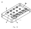
- Fig. 12 illustrates a configuration of a first exemplary embodiment of Japanese Unexamined Patent Application Publication No. 2003-224315 .
- a piezoelectric spring 5 is arranged to each key input button 6. The stress of a user keystroke on the key 6 deforms the piezoelectric spring 5. Then, electromotive force is generated. An electronic circuit is driven by this electromotive force.
- Fig. 13 illustrates a configuration of a second exemplary embodiment disclosed in Japanese Unexamined Patent Application Publication No. 2003-224315 .
- a remote control device includes a piezoelectric plate 25 with a plurality of buttons 26 provided to the top surface thereof, and a switch 28 provided to the position corresponding to the button 26 immediately under the piezoelectric plate 25.
- a press of the button 26 deforms the piezoelectric plate 25, and generates electromotive force in the piezoelectric plate 25.
- This electromotive force is transmitted to an electronic circuit from a supply unit 25a.
- the switch 28 under the piezoelectric plate is pressed.
- the electric circuit detects the press of the button, and a predetermined operation is performed corresponding to the button action.
- the piezoelectric spring 5 that deforms is extremely small for a key operation. It is quite difficult to obtain enough amount of electric power generation if the piezoelectric element, which is an electromotive unit, is small. Accordingly, the abovementioned configuration of the first exemplary embodiment ( Fig. 12 ) of Japanese Unexamined Patent Application Publication No. 2003-224315 is not realistic as a configuration of an electronic equipment with a power generation function.
- the amount of deformation of the piezoelectric plate 25 when a user presses the button 26 is mainly determined by a stroke of the switch 28.
- the amount of deformation of the piezoelectric plate 25 is small.
- the user usually releases the finger from the button 26 when the user has the feel of button operation. Further, the user applies only appropriate pressure for the click pressure of the button 26.
- the piezoelectric plate 25 will not be pressed more than the stroke of the switch 28, and the deformation of the piezoelectric plate 25 will be small.
- electromotive force from the piezoelectric plate 25 is generated not only at the time of pressing the button 26 but at the time of restoration after releasing the user finger from the button 26.
- An exemplary aspect of the present invention is a manual control device with a power generation function including a manual input unit of a touch sensor type, a control unit that detects a direction input in the manual input unit and performs a control operation according to the direction, a power generation unit that is formed of piezoelectric material for power generation and arranged to a bottom side of the manual input unit, a charge unit that charges electric power from the power generation unit, and a power supply unit that supplies the electric power from the charge unit to the control unit.
- the input unit is formed as a touch sensor
- a user input command can be detected as long as the user finger touches the input unit.
- the input command can be detected after the user eases the pressure on the finger, thus the circuit operation can be started after the electric power is generated by restoration of the power generation unit.
- the control unit can start the operation after enough electric power is stored in the charge unit. Then the control unit can stably operate by stable power supply.
- the size of the power generation unit can be half the size thereof when using the electric power generated by only one vibration.
- Fig. 1 illustrates a configuration of a remote control device (manual control device) 100 according to a first exemplary embodiment.
- the remote control device 100 includes an input unit 110, a power generation unit 120, and a circuit unit 200.
- the input unit 110 is a touch sensor type input device.
- the configuration of the touch sensor is not especially limited, as long as it is a sheet-like touch sensor that can detect a region touched by a user finger.
- buttons 111 are printed on a surface part of the touch sensor.
- Each button 111 corresponds to a predetermined command.
- buttons 111 here simply means a mark indicating a region corresponding the command, and does not mean a physical switch device that functions as a detection device.
- the power generation unit 120 converts applied force into voltage.
- the power generation unit 120 includes a piezoelectric element composed of an electrode and a piezoelectric body (piezoelectric material for power generation).
- the arrangement structure of the piezoelectric element in the power generation unit is not especially limited as long as the applied force can be converted into voltage.
- a plurality of piezoelectric elements may be stacked to form a stack.
- a plurality of piezoelectric elements may be arranged over a vibrating plate formed of flexible material, and deformation of the vibrating plate causes the piezoelectric element to generate electric power.
- the power generation unit 120 is placed to a bottom surface side of the touch sensor style input unit 110.
- the power generation unit 120 of the bottom surface is pressed together with the touch sensor input unit 110.
- the power generation unit 120 is not separated and divided by each button 111, but the integrated power generation unit 120 exists under the touch sensor input unit 110.
- the size of the power generation unit 120 is greater than at least one of the size of the buttons 111. Then, pressing force applied to the power generation unit 120 deforms the entire power generation unit.
- the bottom surface side of the input unit 110 is set aside as a space to place only the power generation unit 120.
- the size of the power generation unit 120 is equal to or greater than that of the input unit 110 in the plan view from above, with enough thickness.
- Fig. 1 for the size of the top surface of the power generation unit 120, about 4/5 is the region to place the touch sensor input unit 110, and about 1/5 is the region to place the circuit unit 200.
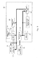
- Fig. 2 is a functional block diagram of the remote control device 100.
- the circuit unit 200 includes a rectification unit 210, a charge unit 220, an operation start control unit 230, a power supply unit 240, a control unit 250, and a transmission unit 260.
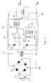
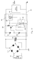
- Fig. 3 is a circuit diagram from the power generation unit 120 to the power supply unit 240.
- the electric power is generated in the power generation unit 120, rectified in the rectification unit 210, and stored to the charge unit 220.
- the operation start control unit 230 supplies an operation start instruction to the power supply unit 240.
- the operation start control unit 230 includes two voltage dividing resistors 231 and 232, a comparator 233, a delay control unit 235, and an output control unit 238, which are provided between a ground line 201 and a voltage line 202.
- the comparator 233 outputs H level when the voltage divided by the voltage dividing resistors 231 and 232 exceeds a reference voltage Vref.
- the reference voltage Vref is generated in a reference voltage generation circuit 234.
- a Zener diode is used as an element for the reference voltage generation circuit 234 that generates the reference voltage.
- the element of the reference voltage generation circuit may not necessarily be a Zener diode, but may be a rechargeable secondary battery, for example, which is charged by the charge unit 220.
- the delay control unit 235 includes a delay time setting capacitor 236 and a delay circuit 237.
- the delay time setting capacitor 236 is provided between the ground line 201 and a comparator output line.
- the delay time is determined by the size of the capacitor 236.
- the delay time is specified to common elapsed time since when the user starts pressing the button until eases the pressure on the user finger.
- the delay circuit 237 supplies a signal to the output control unit 238 when a predetermined voltage is charged to the capacitor 236 and exceeds a predetermined threshold. Then, the output control unit 238 outputs H level of an enable signal to the power supply unit 240.
- the power supply unit 240 is a DC-DC converter, and starts an operation in response to the enable signal output from the operation start control unit 230. Accordingly, when the enable signal is L level, the power supply unit 240 maintains the state to suspend the power supply.
- the power supply unit 240 converts the electric power accumulated in the charge unit 220 into the predetermined voltage and starts the power supply.
- the control unit 250 detects the command output from the input unit 110, and performs a control process according to the command. For example, the control unit 250 generates transmit data corresponding to the command, and transmits the data to the transmission unit 260.
- the transmission unit 260 transmits the transmit data supplied by the control unit 250.
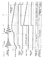
- Fig. 4 is a timing chart for explaining the operation of the remote control device 100.
- a user starts the press operation on the button 111 of the touch sensor input unit 110 at the time T1.
- the force to press the button 111 also presses the power generation unit 120, and thereby generating electric power in the power generation unit 120.
- the rectification unit 220 stores the generated electric power to the charge unit 220 via the rectification unit 210.
- connection node of the voltage line 202 and the charge unit 220 is referred to as a point P, the voltage of this point P will be increased.
- the comparator 233 compares the voltage of the point P, which is divided by the voltage dividing resistors, with the reference voltage Vref.
- the comparator 233 outputs H level when the voltage divided by the voltage dividing resistor exceeds the reference voltage Vref (at the time 2).
- the specified delay time of the capacitor 236 is reached at about when the power generation unit 120 is restored, and the delay circuit 237 supplies the signal to the output control unit 238 (at the time T4). Then, H level of the enable signal is output to the power supply unit 240 from the output control unit 238.
- the power supply unit 240 In response to the H level of the enable signal, the power supply unit 240 starts to supply power.
- control unit 250 In response to the start of power supply, the control unit 250 performs input evaluation of the input unit 110. Specifically, the control unit 250 evaluates which button of the touch sensor input 110 is touched by the user finger.
- the touch sensor input unit 110 can detect the contact position as long as the user finger touches the touch sensor.
- the control unit 250 generates data according to the directed command, and transmits the data to the transmission unit 260. Then, the transmission unit 260 transmits the transmit data.
- a user direction is supplied to devices such as a television and an air-conditioner.
- the control unit 250 and the transmission unit 260 stop the operation when the data transmission from the transmission unit 260 is completed.
- the first exemplary embodiment with such a configuration produces the following exemplary advantages.
- the user input command can be detected even when the user eases the pressure on the finger after pressing the input unit 110.
- the circuit operation may be started after the electric power is generated by the restoration of the power generation unit 120.
- the circuit unit 200 can start the operation after enough electric power is stored to the charge unit.
- the circuit unit 200 can stably operate by stable power supply.
- the size of the power generation unit 120 can be half the size thereof when using the electric power generated by only one vibration.
- the size of the piezoelectric material, which is the power generation unit, cannot be increased.
- the size of the power generation unit 120 can be increased enough, and thereby achieving sufficient electric power for the circuit operation.
- the user Since the user does not have a click feeling like the mechanical switch, the user presses the finger on the touch sensor input unit 110 harder and longer, and thus the power generation unit 120 of the bottom surface side is pressed harder accordingly.
- the amount of electric power generated in the power generation unit 120 increases.
- a modification 1 is explained hereinafter.
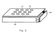
- Fig. 5 illustrates the modification 1.
- the touch sensor input unit 110 and the circuit unit 220 are arranged to the top surface side of the power generation unit 120.
- the circuit unit 200 is arranged to the side surface side of the power generation unit 120, and the entire top surface of the power generation unit 120 is a region to arrange the input unit 110.
- the button 111 can be placed to the central region of the power generation unit 120.
- the central region of the power generation unit 120 is pressed harder at the time of button operation by a user, and thereby further increasing the amount of deformation of the power generation unit 120. Accordingly, a greater amount of electric power generation can be obtained.
- the touch sensor type input unit 110 may be formed of flexible material, such as a resin film.
- both the touch sensor input unit 110 and the power generation unit 120 bend and deform as shown in Fig. 6 .
- buttons 111 are placed to the central region, little pressure is needed to bend and largely deform the power generation unit 120.
- plate material 112 having stiffness such as an organic glass and a plastic plate may be arranged to the bottom surface of the touch sensor type input unit 110.
- the entire plate material 112 presses down the power generation unit 120.
- the power generation unit 120 shrinks as compressed from above.
- the power generation unit 120 can be deformed regardless of the position of the button 111.
- the second exemplary embodiment is characterized in the point that a display unit 113 is included to the bottom surface side of the touch sensor input unit.
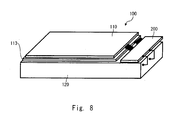
- Fig. 8 illustrates the second exemplary embodiment.
- the display unit 113 is provided between the touch sensor input unit 110 and the power generation unit 120.
- the display unit 113 is a nonvolatile display panel.
- the nonvolatile display panel does not need energy (electric power) to maintain the display state.
- a panel In a case of a liquid crystal display panel, a panel can be used which uses strong dielectric liquid crystals that spontaneously polarize even with zero external voltage.
- the input button is displayed on the display unit 113.
- the touch sensor input unit 110 does not need the button region and the print of letters and symbols.
- the touch sensor input unit 110 must be light transmissive.
- Fig. 9 is a functional block diagram of the second exemplary embodiment.
- a rewritable nonvolatile memory 251 is added to the control unit 250.
- the nonvolatile memory 251 stores an input menu displayed on the display unit 113.
- the control unit 250 controls the display content of the display unit 113, and saves the display content to the nonvolatile memory 251 every time the display content of the display unit 113 is switched.
- Fig. 10 illustrates a display example.
- the display unit 113 displays main buttons 114 in which a user mainly uses, and sub-buttons 115 in which the user supplementarily uses for changing a function or the like.
- buttons 114 are arranged to a central region, and N sub-buttons 114 are arranged to the upper edge part.
- the user specifies often-used command to the main button 114.
- the user simultaneously touches the first main button 114 and the sub-button 115 of function N-1.
- control unit 250 When the control unit 250 detects that the first main button 114 and the sub-button 115 of the function N-1 are simultaneously pressed, the control unit 250 changes the command content of the first main button 114 to the function N-1, and updates the display on the display unit 113. Then, the control unit 250 saves such function setting to the nonvolatile memory 251.
- the user can press the first main button 114 to input the command of the function N-1.
- the second exemplary embodiment brings the following exemplary advantages.
- the remote control device 100 of self-power-generation type does not supply enough electric power to the circuit unit 200 when not used.
- the nonvolatile display unit 113 can maintain the display even when the electric power is not supplied.
- the button must be the one to make the user strongly press the button.
- Small button display might leads to a light touch, thus larger button display than a ball of a finger is desired in order for the user to press hard using with the ball of the finger.
- buttons is limited in order to make the user press the button harder.
- buttons 114 in which the user mainly presses are arranged to the central region.
- buttons 114 By placing large main buttons 114 to the central region in this way, it is possible to make the user press the button hard, and thus obtaining enough amount of generated electric power.
- command content of the main button 114 can be switched, it is possible to handle many kinds of command operations.
- This electric power drives 10 mA load for 10 ms.
- the reference voltage Vref is specified as a reference voltage level necessary for the circuit operation, and when the comparator detects that the voltage level of the point P exceeds the reference voltage level, the enable signal is output.
- the delay time control unit is unnecessary.
- the above exemplary embodiments illustrate the example in which the reference voltage generation unit generates the reference voltage, and the comparator compares the reference voltage with the voltage of the point P.
- start of the charge to the charge unit may be detected using a threshold voltage of a transistor Tr.
- the first and second exemplary embodiments can be combined as desirable by one of ordinary skill in the art.
Landscapes
- Engineering & Computer Science (AREA)
- General Engineering & Computer Science (AREA)
- Theoretical Computer Science (AREA)
- Human Computer Interaction (AREA)
- Physics & Mathematics (AREA)
- General Physics & Mathematics (AREA)
- General Electrical Machinery Utilizing Piezoelectricity, Electrostriction Or Magnetostriction (AREA)
Abstract
A manual control device with a power generation function includes a manual input unit of a touch sensor type, a control unit that detects a direction input in the manual input unit and performs a control operation according to the direction, a power generation unit that is formed of piezoelectric material for power generation and arranged to a bottom side of the manual input unit, a charge unit that charges electric power from the power generation unit, and a power supply unit that supplies the electric power from the charge unit to the control unit. The operation start control unit supplies an operation instruction to the power supply unit after predetermined delay time since the electric power supply from the power generation unit to the charge unit is detected.
Description
- This application is based upon and claims the benefit of priority from Japanese patent application No.
2009-257701, filed on November 11, 2009 - The present invention relates to a manual control device with a power generation function and a remote control device with a power generation function. In particular, the present invention relates to a manual control device with a power generation function and a remote control device with a power generation function that uses electromotive force by piezoelectric effect. For example, the present invention relates a remote controller with a power generation function.
- In recent years, growing awareness of ecology leads to the trend towards devices with a small environmental impact.
- Further, it is desired to reduce the maintenance load.
- From such a point of view, many devices using natural energy such as sunlight, vibration, and heat, have been suggested.
- Batteries are generally used in a remote device, however it is desired to eliminate the maintenance of replacing the batteries and also to reduce the environmental impact.
- For example, a remote control device incorporating an electromotive device using piezoelectric material is disclosed in Japanese Unexamined Patent Application Publication No.
2003-224315 -
Fig. 12 illustrates a configuration of a first exemplary embodiment of Japanese Unexamined Patent Application Publication No.2003-224315 - In this configuration, a
piezoelectric spring 5 is arranged to each key input button 6. The stress of a user keystroke on the key 6 deforms thepiezoelectric spring 5. Then, electromotive force is generated. An electronic circuit is driven by this electromotive force. -
Fig. 13 illustrates a configuration of a second exemplary embodiment disclosed in Japanese Unexamined Patent Application Publication No.2003-224315 - In this configuration, a remote control device includes a
piezoelectric plate 25 with a plurality ofbuttons 26 provided to the top surface thereof, and aswitch 28 provided to the position corresponding to thebutton 26 immediately under thepiezoelectric plate 25. - A press of the
button 26 deforms thepiezoelectric plate 25, and generates electromotive force in thepiezoelectric plate 25. This electromotive force is transmitted to an electronic circuit from asupply unit 25a. When thepiezoelectric plate 25 is deformed by the press of thebutton 26, theswitch 28 under the piezoelectric plate is pressed. The electric circuit detects the press of the button, and a predetermined operation is performed corresponding to the button action. - However, in the above first exemplary embodiment (
Fig. 12 ) of Japanese Unexamined Patent Application Publication No.2003-224315 piezoelectric spring 5 that deforms is extremely small for a key operation. It is quite difficult to obtain enough amount of electric power generation if the piezoelectric element, which is an electromotive unit, is small. Accordingly, the abovementioned configuration of the first exemplary embodiment (Fig. 12 ) of Japanese Unexamined Patent Application Publication No.2003-224315 - In the configuration of the second exemplary embodiment (
Fig. 13 ) of Japanese Unexamined Patent Application Publication No.2003-224315 piezoelectric plate 25 when a user presses thebutton 26 is mainly determined by a stroke of theswitch 28. Thus there is a problem that the amount of deformation of thepiezoelectric plate 25 is small. - It can be considered that the user presses the
button 26 harder to largely deform thepiezoelectric plate 25. - However, when the user has the feel of pressing the
switch 28 on the user finger, it is less common for the user to press thebutton 26 harder. - The user usually releases the finger from the
button 26 when the user has the feel of button operation. Further, the user applies only appropriate pressure for the click pressure of thebutton 26. - Accordingly, the
piezoelectric plate 25 will not be pressed more than the stroke of theswitch 28, and the deformation of thepiezoelectric plate 25 will be small. - Therefore, enough amount of generated electric power cannot be obtained from the piezoelectric plate.
- Furthermore electromotive force from the
piezoelectric plate 25 is generated not only at the time of pressing thebutton 26 but at the time of restoration after releasing the user finger from thebutton 26. - However, in the abovementioned first and the second exemplary embodiments of Japanese Unexamined Patent Application Publication No.
2003-224315 piezoelectric plate 25 is not used at all. - In order to use the electromotive force generated when the
piezoelectric plate 25 is restored, it is necessary to start the electronic circuit after the piezoelectric plate is restored. However by delaying the startup of the electronic equipment, the press of theswitch 28 cannot be detected. This is because that theswitch 28 is also restored when thepiezoelectric plate 25 is restored. Therefore, the present inventors have found a problem that there is a high possibility that in the configuration disclosed in Japanese Unexamined Patent Application Publication No.2003-224315 - An exemplary aspect of the present invention is a manual control device with a power generation function including a manual input unit of a touch sensor type, a control unit that detects a direction input in the manual input unit and performs a control operation according to the direction, a power generation unit that is formed of piezoelectric material for power generation and arranged to a bottom side of the manual input unit, a charge unit that charges electric power from the power generation unit, and a power supply unit that supplies the electric power from the charge unit to the control unit.
- In such a configuration, as the input unit is formed as a touch sensor, a user input command can be detected as long as the user finger touches the input unit. The input command can be detected after the user eases the pressure on the finger, thus the circuit operation can be started after the electric power is generated by restoration of the power generation unit. By setting the start timing of the circuit operation to after restoring the power generation unit, the control unit can start the operation after enough electric power is stored in the charge unit. Then the control unit can stably operate by stable power supply.
- Moreover, it is possible to use the electric power generated by two vibrations (deformation and restoration) from one press operation by the user. Therefore, the size of the power generation unit can be half the size thereof when using the electric power generated by only one vibration.
- The above and other exemplary aspects, advantages and features will be more apparent from the following description of certain exemplary embodiments taken in conjunction with the accompanying drawings, in which:
-
Fig. 1 illustrates a remote control device (manual control device) 100 according to a first exemplary embodiment; -
Fig. 2 is a functional block diagram of theremote control device 100; -
Fig. 3 is a circuit diagram from apower generation unit 120 to apower supply unit 240; -
Fig. 4 is a timing chart for explaining an operation of theremote control device 100; -
Fig. 5 illustrates amodification 1; -
Fig. 6 illustrates amodification 2; -
Fig. 7 illustrates themodification 2; -
Fig. 8 illustrates a second exemplary embodiment; -
Fig. 9 is a functional block diagram of the second exemplary embodiment. -
Fig. 10 illustrates a display example; -
Fig. 11 illustrates a modification; -
Fig. 12 illustrates a configuration of a first exemplary embodiment disclosed in Japanese Unexamined Patent Application Publication No.2003-224315 -
Fig. 13 illustrates a configuration of a second exemplary embodiment disclosed in Japanese Unexamined Patent Application Publication No.2003-224315 - Hereinafter, exemplary embodiments of the present invention are described with reference to the drawings.
-
Fig. 1 illustrates a configuration of a remote control device (manual control device) 100 according to a first exemplary embodiment. - The
remote control device 100 includes aninput unit 110, apower generation unit 120, and acircuit unit 200. - The
input unit 110 is a touch sensor type input device. - The configuration of the touch sensor is not especially limited, as long as it is a sheet-like touch sensor that can detect a region touched by a user finger.
- A plurality of
buttons 111 are printed on a surface part of the touch sensor. - A letter, a symbol, or the like are placed to each
button 111. Eachbutton 111 corresponds to a predetermined command. - Note that the
button 111 here simply means a mark indicating a region corresponding the command, and does not mean a physical switch device that functions as a detection device. - The
power generation unit 120 converts applied force into voltage. - The
power generation unit 120 includes a piezoelectric element composed of an electrode and a piezoelectric body (piezoelectric material for power generation). - The arrangement structure of the piezoelectric element in the power generation unit is not especially limited as long as the applied force can be converted into voltage. For example, a plurality of piezoelectric elements may be stacked to form a stack. Alternatively, a plurality of piezoelectric elements may be arranged over a vibrating plate formed of flexible material, and deformation of the vibrating plate causes the piezoelectric element to generate electric power.
- The arrangement and the size of the
input unit 110 and thepower generation unit 120 are explained here. - The
power generation unit 120 is placed to a bottom surface side of the touch sensorstyle input unit 110. When a user presses thebutton 111 of theinput unit 110 using a finger, thepower generation unit 120 of the bottom surface is pressed together with the touchsensor input unit 110. - The
power generation unit 120 is not separated and divided by eachbutton 111, but the integratedpower generation unit 120 exists under the touchsensor input unit 110. - In a plan view from above, the size of the
power generation unit 120 is greater than at least one of the size of thebuttons 111. Then, pressing force applied to thepower generation unit 120 deforms the entire power generation unit. - The bottom surface side of the
input unit 110 is set aside as a space to place only thepower generation unit 120. - The size of the
power generation unit 120 is equal to or greater than that of theinput unit 110 in the plan view from above, with enough thickness. - In
Fig. 1 , for the size of the top surface of thepower generation unit 120, about 4/5 is the region to place the touchsensor input unit 110, and about 1/5 is the region to place thecircuit unit 200. -
Fig. 2 is a functional block diagram of theremote control device 100. - The
circuit unit 200 includes arectification unit 210, acharge unit 220, an operationstart control unit 230, apower supply unit 240, acontrol unit 250, and atransmission unit 260. -
Fig. 3 is a circuit diagram from thepower generation unit 120 to thepower supply unit 240. - The electric power is generated in the
power generation unit 120, rectified in therectification unit 210, and stored to thecharge unit 220. - The operation start
control unit 230 supplies an operation start instruction to thepower supply unit 240. - The operation start
control unit 230 includes twovoltage dividing resistors comparator 233, adelay control unit 235, and anoutput control unit 238, which are provided between aground line 201 and avoltage line 202. - The
comparator 233 outputs H level when the voltage divided by thevoltage dividing resistors - The reference voltage Vref is generated in a reference
voltage generation circuit 234. - A Zener diode is used as an element for the reference
voltage generation circuit 234 that generates the reference voltage. - The element of the reference voltage generation circuit may not necessarily be a Zener diode, but may be a rechargeable secondary battery, for example, which is charged by the
charge unit 220. - The
delay control unit 235 includes a delaytime setting capacitor 236 and adelay circuit 237. - The delay
time setting capacitor 236 is provided between theground line 201 and a comparator output line. - When the H level is output from the
comparator 233, the electric power is charged to thecapacitor 236 of thedelay control unit 235. - The delay time is determined by the size of the
capacitor 236. - It is preferable to specify the delay time to common elapsed time since when the user starts pressing the button until eases the pressure on the user finger.
- The
delay circuit 237 supplies a signal to theoutput control unit 238 when a predetermined voltage is charged to thecapacitor 236 and exceeds a predetermined threshold. Then, theoutput control unit 238 outputs H level of an enable signal to thepower supply unit 240. - The
power supply unit 240 is a DC-DC converter, and starts an operation in response to the enable signal output from the operationstart control unit 230. Accordingly, when the enable signal is L level, thepower supply unit 240 maintains the state to suspend the power supply. - If the enable signal becomes H level, the
power supply unit 240 converts the electric power accumulated in thecharge unit 220 into the predetermined voltage and starts the power supply. - The
control unit 250 detects the command output from theinput unit 110, and performs a control process according to the command. For example, thecontrol unit 250 generates transmit data corresponding to the command, and transmits the data to thetransmission unit 260. - The
transmission unit 260 transmits the transmit data supplied by thecontrol unit 250. -
Fig. 4 is a timing chart for explaining the operation of theremote control device 100. - The operation of the
remote control device 100 is explained with reference toFig. 4 . - A user starts the press operation on the
button 111 of the touchsensor input unit 110 at the time T1. - At this time, the force to press the
button 111 also presses thepower generation unit 120, and thereby generating electric power in thepower generation unit 120. - The
rectification unit 220 stores the generated electric power to thecharge unit 220 via therectification unit 210. - Further, if a connection node of the
voltage line 202 and thecharge unit 220 is referred to as a point P, the voltage of this point P will be increased. - The
comparator 233 compares the voltage of the point P, which is divided by the voltage dividing resistors, with the reference voltage Vref. - The
comparator 233 outputs H level when the voltage divided by the voltage dividing resistor exceeds the reference voltage Vref (at the time 2). - When H level is output from the
comparator 233, the electric power is stored to thecapacitor 236. However a signal is not output from thedelay circuit 237 till the delay time specified by thecapacitor 236. - The user presses the
button 111, and then starts to ease the pressure on the finger when the user feels that a predetermined input is completed (at the time T3). Then, thepower generation unit 120 is restored and the electric power is generated at this time. The generated electric power is also stored to thecharge unit 220. - The specified delay time of the
capacitor 236 is reached at about when thepower generation unit 120 is restored, and thedelay circuit 237 supplies the signal to the output control unit 238 (at the time T4). Then, H level of the enable signal is output to thepower supply unit 240 from theoutput control unit 238. - In response to the H level of the enable signal, the
power supply unit 240 starts to supply power. - In response to the start of power supply, the
control unit 250 performs input evaluation of theinput unit 110. Specifically, thecontrol unit 250 evaluates which button of thetouch sensor input 110 is touched by the user finger. - Even if the user eases the pressure on the finger, the touch
sensor input unit 110 can detect the contact position as long as the user finger touches the touch sensor. - The
control unit 250 generates data according to the directed command, and transmits the data to thetransmission unit 260. Then, thetransmission unit 260 transmits the transmit data. - For example, a user direction is supplied to devices such as a television and an air-conditioner.
- The
control unit 250 and thetransmission unit 260 stop the operation when the data transmission from thetransmission unit 260 is completed. - The first exemplary embodiment with such a configuration produces the following exemplary advantages.
- (1) Since the
input unit 110 is formed as a touch sensor, a user input command can be detected as long as the user finger is touching theinput unit 110. - Accordingly, the user input command can be detected even when the user eases the pressure on the finger after pressing the
input unit 110. - As the input command can be detected even after the user eases the pressure on the finger, the circuit operation may be started after the electric power is generated by the restoration of the
power generation unit 120. - By setting the start timing of the circuit operation to after the restoration of the
power generation unit 120, thecircuit unit 200 can start the operation after enough electric power is stored to the charge unit. - Therefore, the
circuit unit 200 can stably operate by stable power supply. - As described so far, it is possible to use the electric power generated by two vibrations (deformation and restoration) from one press operation by the user. Therefore, the size of the
power generation unit 120 can be half the size thereof when using the electric power generated by only one vibration. - (2) According to this exemplary embodiment, as the
input unit 110 is formed of a simple sheet-like member, which is a touch sensor, the bottom surface side of theinput unit 110 can be set aside as a space to place only thepower generation unit 120. - In the configuration disclosed in Japanese Unexamined Patent Application Publication No.
2003-224315 - Therefore, the size of the piezoelectric material, which is the power generation unit, cannot be increased.
- In this regard, in this exemplary embodiment, the size of the
power generation unit 120 can be increased enough, and thereby achieving sufficient electric power for the circuit operation. - (3) By forming the
input unit 110 as a touch sensor, a press stroke is not necessary unlike the mechanical switch, for example. - Since the user does not have a click feeling like the mechanical switch, the user presses the finger on the touch
sensor input unit 110 harder and longer, and thus thepower generation unit 120 of the bottom surface side is pressed harder accordingly. - Thus, the amount of electric power generated in the
power generation unit 120 increases. - A
modification 1 is explained hereinafter. -
Fig. 5 illustrates themodification 1. - In the above first exemplary embodiment, the touch
sensor input unit 110 and thecircuit unit 220 are arranged to the top surface side of thepower generation unit 120. - On the other hand, in the
modification 1, thecircuit unit 200 is arranged to the side surface side of thepower generation unit 120, and the entire top surface of thepower generation unit 120 is a region to arrange theinput unit 110. - As the entire top surface of the
power generation unit 120 can be theinput unit 110, thebutton 111 can be placed to the central region of thepower generation unit 120. - Thus, the central region of the
power generation unit 120 is pressed harder at the time of button operation by a user, and thereby further increasing the amount of deformation of thepower generation unit 120. Accordingly, a greater amount of electric power generation can be obtained. - The touch sensor
type input unit 110 may be formed of flexible material, such as a resin film. - In such case, if the user presses the touch
sensor input unit 110, both the touchsensor input unit 110 and thepower generation unit 120 bend and deform as shown inFig. 6 . - If the
button 111 is placed to the central region, little pressure is needed to bend and largely deform thepower generation unit 120. - Alternatively, as illustrated in
Fig. 7 ,plate material 112 having stiffness such as an organic glass and a plastic plate may be arranged to the bottom surface of the touch sensortype input unit 110. - In such a case, when the user presses the touch
sensor input unit 110 with a finger, theentire plate material 112 presses down thepower generation unit 120. Thus thepower generation unit 120 shrinks as compressed from above. - As the
plate material 112 evenly presses down the top surface of thepower generation unit 120, thepower generation unit 120 can be deformed regardless of the position of thebutton 111. - Next, a second exemplary embodiment of the present invention is described.
- The second exemplary embodiment is characterized in the point that a
display unit 113 is included to the bottom surface side of the touch sensor input unit. -
Fig. 8 illustrates the second exemplary embodiment. - The
display unit 113 is provided between the touchsensor input unit 110 and thepower generation unit 120. - The
display unit 113 is a nonvolatile display panel. - The nonvolatile display panel does not need energy (electric power) to maintain the display state.
- In a case of a liquid crystal display panel, a panel can be used which uses strong dielectric liquid crystals that spontaneously polarize even with zero external voltage.
- The input button is displayed on the
display unit 113. - Accordingly, the touch
sensor input unit 110 does not need the button region and the print of letters and symbols. - However, the touch
sensor input unit 110 must be light transmissive. -
Fig. 9 is a functional block diagram of the second exemplary embodiment. - In
Fig. 9 , a rewritablenonvolatile memory 251 is added to thecontrol unit 250. - The
nonvolatile memory 251 stores an input menu displayed on thedisplay unit 113. - The
control unit 250 controls the display content of thedisplay unit 113, and saves the display content to thenonvolatile memory 251 every time the display content of thedisplay unit 113 is switched. -
Fig. 10 illustrates a display example. - The
display unit 113 displaysmain buttons 114 in which a user mainly uses, and sub-buttons 115 in which the user supplementarily uses for changing a function or the like. - In
Fig. 10 , fourmain buttons 114 are arranged to a central region, and N sub-buttons 114 are arranged to the upper edge part. - The user specifies often-used command to the
main button 114. - For example, suppose that the user attempts allocate the content of the function N-1 to the first
main button 114. - The user simultaneously touches the first
main button 114 and thesub-button 115 of function N-1. - When the
control unit 250 detects that the firstmain button 114 and thesub-button 115 of the function N-1 are simultaneously pressed, thecontrol unit 250 changes the command content of the firstmain button 114 to the function N-1, and updates the display on thedisplay unit 113. Then, thecontrol unit 250 saves such function setting to thenonvolatile memory 251. - After that, the user can press the first
main button 114 to input the command of the function N-1. - The second exemplary embodiment brings the following exemplary advantages.
- In the
remote control device 100 of self-power-generation type does not supply enough electric power to thecircuit unit 200 when not used. - In this regard, in the second exemplary embodiment, the
nonvolatile display unit 113 can maintain the display even when the electric power is not supplied. - Further, as the electric power is generated by a user finger press, the button must be the one to make the user strongly press the button.
- Small button display might leads to a light touch, thus larger button display than a ball of a finger is desired in order for the user to press hard using with the ball of the finger..
- Accordingly, the number of buttons is limited in order to make the user press the button harder.
- In this regard, in the second exemplary embodiment, four of the
large buttons 114 in which the user mainly presses are arranged to the central region. - By placing large
main buttons 114 to the central region in this way, it is possible to make the user press the button hard, and thus obtaining enough amount of generated electric power. - Furthermore, as the command content of the
main button 114 can be switched, it is possible to handle many kinds of command operations. - One example is illustrated hereinafter.
- As a result of an experiment using a power generation unit with the same size as a common remote control, a capacitor of 47 µF can be charged to 4.4 V in one press operation.
- This electric power drives 10 mA load for 10 ms.
- The present invention is not limited to the above exemplary embodiments, but may be changed without departing from the scope of the present invention.
- The case is explained in which the operation start control unit supplies the enable signal to the power supply unit after the delay time which is delayed by the delay time setting capacitor. However, the following case can be possible.
- The reference voltage Vref is specified as a reference voltage level necessary for the circuit operation, and when the comparator detects that the voltage level of the point P exceeds the reference voltage level, the enable signal is output.
- In this case, the delay time control unit is unnecessary.
- The above exemplary embodiments illustrate the example in which the reference voltage generation unit generates the reference voltage, and the comparator compares the reference voltage with the voltage of the point P. However as illustrated in
Fig. 11 , start of the charge to the charge unit may be detected using a threshold voltage of a transistor Tr. - The first and second exemplary embodiments can be combined as desirable by one of ordinary skill in the art.
- While the invention has been described in terms of several exemplary embodiments, those skilled in the art will recognize that the invention can be practiced with various modifications within the spirit and scope of the appended claims and the invention is not limited to the examples described above.
- Further, the scope of the claims is not limited by the exemplary embodiments described above.
- Furthermore, it is noted that, Applicant's intent is to encompass equivalents of all claim elements, even if amended later during prosecution.
Claims (9)
- A manual control device with a power generation function comprising:a manual input unit of a touch sensor type;a control unit that detects a direction input in the manual input unit and performs a control operation according to the direction;a power generation unit that is formed of piezoelectric material for power generation and arranged to a bottom side of the manual input unit;a charge unit that charges electric power from the power generation unit; anda power supply unit that supplies the electric power from the charge unit to the control unit.
- The manual control device with the power generation function according to Claim 1, further comprising an operation start control unit that supplies an operation instruction to the power supply unit after the electric power necessary for an operation of the control unit is charged to the charge unit.
- The manual control device with the power generation function according to Claim 2, wherein the operation start control unit supplies the operation instruction to the power supply unit after predetermined delay time since the electric power supply from the power generation unit to the charge unit is detected.
- The manual control device with the power generation function according to Claim 3, wherein
the operation start control unit includes a delay time setting capacitor, and
the delay time is specified by time to charge predetermined electric power to the delay time setting capacitor. - The manual control device with the power generation function according to Claim 2, wherein the operation start control unit supplies the operation instruction to the power supply unit when the operation start control unit detects that an amount of charged electric power in the charge unit reaches a predetermined value.
- The manual control device with the power generation function according to Claim 2, wherein the control unit detects a region touched by a user finger after the user finger eases pressure on the finger to press the manual input unit.
- The manual control device with the power generation function according to any of Claims 1 to 6, further comprising a nonvolatile display unit provided between the manual input unit and the power generation unit.
- The manual control device with the power generation function according to Claim 7, further comprising a nonvolatile memory that stores a correspondence between a button displayed on the nonvolatile display unit and an input command specified to the button
- A remote control device with a power generation function incorporating a radio wave transmission unit in the manual control device with the power generation function according to any of Claims 1 to 8.
Applications Claiming Priority (1)
| Application Number | Priority Date | Filing Date | Title |
|---|---|---|---|
| JP2009257701A JP5530155B2 (en) | 2009-11-11 | 2009-11-11 | Manual operation equipment with power generation function, remote control device with power generation function |
Publications (1)
| Publication Number | Publication Date |
|---|---|
| EP2323015A2 true EP2323015A2 (en) | 2011-05-18 |
Family
ID=43568294
Family Applications (1)
| Application Number | Title | Priority Date | Filing Date |
|---|---|---|---|
| EP10014508A Withdrawn EP2323015A2 (en) | 2009-11-11 | 2010-11-11 | Manual control device with power generation function and remote control device with power generation function |
Country Status (4)
| Country | Link |
|---|---|
| US (1) | US20110109201A1 (en) |
| EP (1) | EP2323015A2 (en) |
| JP (1) | JP5530155B2 (en) |
| CN (1) | CN102142792A (en) |
Cited By (5)
| Publication number | Priority date | Publication date | Assignee | Title |
|---|---|---|---|---|
| WO2014026127A1 (en) * | 2012-08-09 | 2014-02-13 | Qualcomm Incorporated | Apparatus and method for charging a mobile device |
| FR3030157A1 (en) * | 2014-12-15 | 2016-06-17 | Commissariat Energie Atomique | CIRCUIT FOR COMPARING A VOLTAGE AT A THRESHOLD |
| EP3041128A4 (en) * | 2013-08-29 | 2016-08-24 | Panasonic Ip Man Co Ltd | Environmental power generation device |
| DE102015015417A1 (en) | 2015-11-27 | 2017-06-01 | Audi Ag | Operating device for a motor vehicle and method for generating a haptic signal |
| US9972190B2 (en) | 2015-12-15 | 2018-05-15 | Stmicroelectronics (Crolles 2) Sas | Event detector |
Families Citing this family (15)
| Publication number | Priority date | Publication date | Assignee | Title |
|---|---|---|---|---|
| EP2793388B1 (en) * | 2009-11-11 | 2017-09-13 | Soundpower corporation | Electric apparatus provided with power generating function |
| FR2973973B1 (en) * | 2011-04-08 | 2013-04-19 | Schneider Electric Ind Sas | METHOD FOR REMOTELY CONTROLLING AN ELECTRICAL APPARATUS AND CONTROL DEVICE FOR IMPLEMENTING SUCH A METHOD |
| FR2973918B1 (en) | 2011-04-08 | 2013-04-26 | Schneider Electric Ind Sas | DEVICE FOR REMOTELY CONTROLLING AN ELECTRICAL APPARATUS AND METHOD FOR STARTING THE DEVICE |
| WO2013136691A1 (en) * | 2012-03-16 | 2013-09-19 | パナソニック株式会社 | Generator device and electrical apparatus using same |
| JP6239761B2 (en) * | 2013-08-23 | 2017-11-29 | アップル インコーポレイテッド | Remote control device |
| EP3098866B1 (en) | 2014-01-22 | 2020-02-12 | Murata Manufacturing Co., Ltd. | Piezoelectric power generation module and remote controller |
| JP2015182548A (en) * | 2014-03-24 | 2015-10-22 | レシップホールディングス株式会社 | Getting-off button device |
| JP6350052B2 (en) * | 2014-07-11 | 2018-07-04 | Toto株式会社 | Remote control device and toilet system |
| CN108133858B (en) * | 2015-07-31 | 2019-07-26 | 武汉领普科技有限公司 | Power self-sufficient multi-button switch device |
| CN105718116A (en) * | 2016-02-01 | 2016-06-29 | 京东方科技集团股份有限公司 | Touch panel, manufacturing method thereof and touch display screen |
| CN107852080A (en) * | 2016-02-04 | 2018-03-27 | 廖淑辉 | Self-generating remote controller and its application |
| JP2019090934A (en) * | 2017-11-15 | 2019-06-13 | 凸版印刷株式会社 | Driving device, method for driving electronic display medium, and display device |
| KR102867760B1 (en) * | 2021-03-05 | 2025-10-13 | 삼성전자주식회사 | Remote controller and controlling method thereof |
| CN115421402A (en) * | 2021-05-16 | 2022-12-02 | 武汉领普科技有限公司 | Processing method and control system of self-generating switch |
| CN113504842A (en) * | 2021-06-11 | 2021-10-15 | 电子科技大学 | Touch screen and production process thereof |
Citations (2)
| Publication number | Priority date | Publication date | Assignee | Title |
|---|---|---|---|---|
| JP2003224315A (en) | 2002-01-30 | 2003-08-08 | Sony Corp | Power generation device, power supply device, remote control device, and electronic equipment |
| JP2009257701A (en) | 2008-04-18 | 2009-11-05 | Panasonic Electric Works Co Ltd | Ceiling heating apparatus |
Family Cites Families (11)
| Publication number | Priority date | Publication date | Assignee | Title |
|---|---|---|---|---|
| US7800592B2 (en) * | 2005-03-04 | 2010-09-21 | Apple Inc. | Hand held electronic device with multiple touch sensing devices |
| US6438242B1 (en) * | 1999-09-07 | 2002-08-20 | The United States Of America As Represented By The Secretary Of The Navy | Acoustic transducer panel |
| US7256505B2 (en) * | 2003-03-05 | 2007-08-14 | Microstrain, Inc. | Shaft mounted energy harvesting for wireless sensor operation and data transmission |
| JP4346892B2 (en) * | 2002-10-31 | 2009-10-21 | 富士通テン株式会社 | Electronic program guide display control apparatus, electronic program guide display control method, and electronic program guide display control program |
| JP3880569B2 (en) * | 2003-10-27 | 2007-02-14 | 株式会社ユーエスシー | Wireless remote control device |
| US20050202867A1 (en) * | 2004-03-09 | 2005-09-15 | Eastman Kodak Company | Interactive display device |
| JP2006048302A (en) * | 2004-08-03 | 2006-02-16 | Sony Corp | Piezoelectric composite device, manufacturing method thereof, handling method thereof, control method thereof, input / output device and electronic apparatus |
| JP2008140207A (en) * | 2006-12-04 | 2008-06-19 | Seiko Epson Corp | Input power generation device, input power generation output device, electronic device and electronic book |
| US9857872B2 (en) * | 2007-12-31 | 2018-01-02 | Apple Inc. | Multi-touch display screen with localized tactile feedback |
| JP4838280B2 (en) * | 2008-03-31 | 2011-12-14 | 太平洋セメント株式会社 | Touch panel type input device |
| US8030825B2 (en) * | 2008-09-19 | 2011-10-04 | The United States Of America As Represented By The Secretary Of The Navy | Piezoelectric generator and method |
-
2009
- 2009-11-11 JP JP2009257701A patent/JP5530155B2/en not_active Expired - Fee Related
-
2010
- 2010-11-05 CN CN2010105370401A patent/CN102142792A/en active Pending
- 2010-11-10 US US12/926,342 patent/US20110109201A1/en not_active Abandoned
- 2010-11-11 EP EP10014508A patent/EP2323015A2/en not_active Withdrawn
Patent Citations (2)
| Publication number | Priority date | Publication date | Assignee | Title |
|---|---|---|---|---|
| JP2003224315A (en) | 2002-01-30 | 2003-08-08 | Sony Corp | Power generation device, power supply device, remote control device, and electronic equipment |
| JP2009257701A (en) | 2008-04-18 | 2009-11-05 | Panasonic Electric Works Co Ltd | Ceiling heating apparatus |
Cited By (7)
| Publication number | Priority date | Publication date | Assignee | Title |
|---|---|---|---|---|
| WO2014026127A1 (en) * | 2012-08-09 | 2014-02-13 | Qualcomm Incorporated | Apparatus and method for charging a mobile device |
| EP3041128A4 (en) * | 2013-08-29 | 2016-08-24 | Panasonic Ip Man Co Ltd | Environmental power generation device |
| FR3030157A1 (en) * | 2014-12-15 | 2016-06-17 | Commissariat Energie Atomique | CIRCUIT FOR COMPARING A VOLTAGE AT A THRESHOLD |
| EP3035530A1 (en) * | 2014-12-15 | 2016-06-22 | Commissariat A L'energie Atomique Et Aux Energies Alternatives | Circuit for comparing a voltage to a threshold |
| US9742219B2 (en) | 2014-12-15 | 2017-08-22 | Commissariat à l'énergie atomique et aux énergies alternatives | Circuit for comparing a voltage with a threshold |
| DE102015015417A1 (en) | 2015-11-27 | 2017-06-01 | Audi Ag | Operating device for a motor vehicle and method for generating a haptic signal |
| US9972190B2 (en) | 2015-12-15 | 2018-05-15 | Stmicroelectronics (Crolles 2) Sas | Event detector |
Also Published As
| Publication number | Publication date |
|---|---|
| JP2011103729A (en) | 2011-05-26 |
| CN102142792A (en) | 2011-08-03 |
| JP5530155B2 (en) | 2014-06-25 |
| US20110109201A1 (en) | 2011-05-12 |
Similar Documents
| Publication | Publication Date | Title |
|---|---|---|
| US20110109201A1 (en) | Manual control device with power generation function and remote control device with power generation function | |
| KR101562306B1 (en) | Tactile sensation providing apparatus and control method for tactile sensation providing apparatus | |
| JP4672075B2 (en) | Input device | |
| KR101477717B1 (en) | Tactile sensation providing apparatus | |
| JP5529663B2 (en) | Input device | |
| EP2472368A1 (en) | Input device | |
| US9448629B2 (en) | Multi-mode tactile sensation providing device | |
| US9208663B2 (en) | Input apparatus and control method for input apparatus | |
| US20120162114A1 (en) | Tactile sensation providing apparatus and control method for tactile sensation providing apparatus | |
| EP2278444A2 (en) | Portable terminal | |
| US9335858B2 (en) | Input device | |
| WO2001004736A1 (en) | Keyboard type input device and portable information processor | |
| US20170038841A1 (en) | Tactile sensation providing apparatus | |
| US9798410B2 (en) | Input device and method for controlling input device | |
| CN111623863A (en) | Electronic scale control method and electronic scale | |
| JP5710214B2 (en) | Input device and control method of input device | |
| US20150160727A1 (en) | Electronic device and control method of electronic device | |
| US9329712B2 (en) | Electronic device having changeable touch receiving region | |
| US9720531B2 (en) | Electronic device | |
| CN209357036U (en) | A flexible touch screen structure | |
| EP3376349A1 (en) | Tactile sensation presentation device and electronic device | |
| CN212625303U (en) | Keyboard and key module thereof | |
| US20120306755A1 (en) | Touch keyboard | |
| KR20130036328A (en) | Tactile sensation providing apparatus and control method for tactile sensation providing apparatus | |
| CN207037607U (en) | Light and thin type piezoelectricity tactile feedback keyboard |
Legal Events
| Date | Code | Title | Description |
|---|---|---|---|
| PUAI | Public reference made under article 153(3) epc to a published international application that has entered the european phase |
Free format text: ORIGINAL CODE: 0009012 |
|
| AK | Designated contracting states |
Kind code of ref document: A2 Designated state(s): AL AT BE BG CH CY CZ DE DK EE ES FI FR GB GR HR HU IE IS IT LI LT LU LV MC MK MT NL NO PL PT RO RS SE SI SK SM TR |
|
| AX | Request for extension of the european patent |
Extension state: BA ME |
|
| STAA | Information on the status of an ep patent application or granted ep patent |
Free format text: STATUS: THE APPLICATION HAS BEEN WITHDRAWN |
|
| 18W | Application withdrawn |
Effective date: 20141204 |