EP2323013A2 - Wireless remote control system - Google Patents
Wireless remote control system Download PDFInfo
- Publication number
- EP2323013A2 EP2323013A2 EP10154768A EP10154768A EP2323013A2 EP 2323013 A2 EP2323013 A2 EP 2323013A2 EP 10154768 A EP10154768 A EP 10154768A EP 10154768 A EP10154768 A EP 10154768A EP 2323013 A2 EP2323013 A2 EP 2323013A2
- Authority
- EP
- European Patent Office
- Prior art keywords
- frequency
- remote controller
- wireless
- control system
- decision module
- Prior art date
- Legal status (The legal status is an assumption and is not a legal conclusion. Google has not performed a legal analysis and makes no representation as to the accuracy of the status listed.)
- Granted
Links
Images

Classifications
-
- G—PHYSICS
- G08—SIGNALLING
- G08C—TRANSMISSION SYSTEMS FOR MEASURED VALUES, CONTROL OR SIMILAR SIGNALS
- G08C17/00—Arrangements for transmitting signals characterised by the use of a wireless electrical link
-
- G—PHYSICS
- G01—MEASURING; TESTING
- G01S—RADIO DIRECTION-FINDING; RADIO NAVIGATION; DETERMINING DISTANCE OR VELOCITY BY USE OF RADIO WAVES; LOCATING OR PRESENCE-DETECTING BY USE OF THE REFLECTION OR RERADIATION OF RADIO WAVES; ANALOGOUS ARRANGEMENTS USING OTHER WAVES
- G01S11/00—Systems for determining distance or velocity not using reflection or reradiation
- G01S11/14—Systems for determining distance or velocity not using reflection or reradiation using ultrasonic, sonic or infrasonic waves
-
- G—PHYSICS
- G06—COMPUTING OR CALCULATING; COUNTING
- G06F—ELECTRIC DIGITAL DATA PROCESSING
- G06F3/00—Input arrangements for transferring data to be processed into a form capable of being handled by the computer; Output arrangements for transferring data from processing unit to output unit, e.g. interface arrangements
- G06F3/01—Input arrangements or combined input and output arrangements for interaction between user and computer
- G06F3/017—Gesture based interaction, e.g. based on a set of recognized hand gestures
-
- G—PHYSICS
- G06—COMPUTING OR CALCULATING; COUNTING
- G06F—ELECTRIC DIGITAL DATA PROCESSING
- G06F3/00—Input arrangements for transferring data to be processed into a form capable of being handled by the computer; Output arrangements for transferring data from processing unit to output unit, e.g. interface arrangements
- G06F3/01—Input arrangements or combined input and output arrangements for interaction between user and computer
- G06F3/03—Arrangements for converting the position or the displacement of a member into a coded form
- G06F3/033—Pointing devices displaced or positioned by the user, e.g. mice, trackballs, pens or joysticks; Accessories therefor
- G06F3/0346—Pointing devices displaced or positioned by the user, e.g. mice, trackballs, pens or joysticks; Accessories therefor with detection of the device orientation or free movement in a three-dimensional [3D] space, e.g. 3D mice, 6-DOF [six degrees of freedom] pointers using gyroscopes, accelerometers or tilt-sensors
-
- G—PHYSICS
- G06—COMPUTING OR CALCULATING; COUNTING
- G06F—ELECTRIC DIGITAL DATA PROCESSING
- G06F3/00—Input arrangements for transferring data to be processed into a form capable of being handled by the computer; Output arrangements for transferring data from processing unit to output unit, e.g. interface arrangements
- G06F3/01—Input arrangements or combined input and output arrangements for interaction between user and computer
- G06F3/03—Arrangements for converting the position or the displacement of a member into a coded form
- G06F3/033—Pointing devices displaced or positioned by the user, e.g. mice, trackballs, pens or joysticks; Accessories therefor
- G06F3/038—Control and interface arrangements therefor, e.g. drivers or device-embedded control circuitry
-
- G—PHYSICS
- G06—COMPUTING OR CALCULATING; COUNTING
- G06F—ELECTRIC DIGITAL DATA PROCESSING
- G06F2203/00—Indexing scheme relating to G06F3/00 - G06F3/048
- G06F2203/038—Indexing scheme relating to G06F3/038
- G06F2203/0383—Remote input, i.e. interface arrangements in which the signals generated by a pointing device are transmitted to a PC at a remote location, e.g. to a PC in a LAN
-
- G—PHYSICS
- G06—COMPUTING OR CALCULATING; COUNTING
- G06F—ELECTRIC DIGITAL DATA PROCESSING
- G06F2203/00—Indexing scheme relating to G06F3/00 - G06F3/048
- G06F2203/038—Indexing scheme relating to G06F3/038
- G06F2203/0384—Wireless input, i.e. hardware and software details of wireless interface arrangements for pointing devices
-
- G—PHYSICS
- G08—SIGNALLING
- G08C—TRANSMISSION SYSTEMS FOR MEASURED VALUES, CONTROL OR SIMILAR SIGNALS
- G08C2201/00—Transmission systems of control signals via wireless link
- G08C2201/30—User interface
- G08C2201/32—Remote control based on movements, attitude of remote control device
Definitions
- the present invention relates to remote control systems.
- the present invention relates to wireless remote control systems that determines control signals based on users' gestures.
- Wireless control of electrical/electronic devices is becoming indispensable. For instance, garage door opening, audio/video equipment (TV) control, air conditioner control, projector control, wireless mouse, and so on.
- Wireless controllers provide the convenience that saves users from walking to the devices that they want to control.
- Most commercial wireless controllers at the present time are based on radio-frequency (RF) or infrared signals to communicate the intended commands to the controlled devices.
- RF radio-frequency
- U.S. patent 4,578,674 discloses a wireless cursor control using a position device (mouse).
- two detectors disposed at the computer side detect how a wireless mouse moves based the ultrasonic signal emitted by the mouse; a cursor on a display panel is accordingly controlled.
- the frequencies detected by the two detectors (represented as f 1 and f 2 ) at the computer side are different from the original frequency of the ultrasonic signal emitted by the mouse (represented as f 0 ) .
- the microprocessor at the computer side first calculates the difference between f 1 and f 0 and the difference between f 2 and f 0 . According to the two differences, the microprocessor estimates the direction and velocity of the mouse motion relative to the detectors. Then the patent calculates the movement of the position device from an initial location and moves the cursor on the display accordingly.
- U.S. patent 4,654,648 also utilizes acoustic signal emitted from the controller and measure the time difference between signals arriving at several different acoustic receivers. Using triangulation, the patent can determine the position of the controller. This patent does not teach a wireless remote control based on Doppler effect induced from the motion of the controller.
- U.S. patent 5,999,167 teaches another wireless cursor control system based on ultrasonic signal.
- the ultrasonic signal is emitted from the base unit and the remote controller is equipped with multiple ultrasonic receivers.
- the phases of the received ultrasonic signals are captured and compared to determine the angular orientation of the remote unit and therefore cursor movement on the display can be accordingly controlled according to said detected orientation change.
- U.S. patent application US2007/0115252 is based on US patent 5,999,167 and includes an extra sensitivity adjuster to extend the application of US patent 5,999,167 to the cases when the remote controller is at a far distance away from the base unit.
- U.S. patent 6,504,526 presents a wireless pointing device based on infrared signal. Multiple receivers receive infrared pulse-train signal from a transmitter. As the remote unit is moved, wavefront will arrive at different receivers at different times. By detecting the peaks in the received signal's amplitude (or envelope) and compare their arrival times, movement along a particular direction of the remote control unit can be detected.
- the wireless remote control system also operates based on the concept of the Doppler effect induced by the movement of a remote controller, which emits a wireless signal consisting of tone(s) of one frequency or a group of several frequencies.
- the host side in the invention does not have to know the exact frequency of the wireless signal emitted by said remote controller. Accordingly, the infrared emitter and infrared receiver in U.S. patent 4,578,674 can be omitted.
- One embodiment according to the invention is a wireless remote control system including a remote controller, a plurality of detectors, and a decision module.
- the detectors are used for detecting a wireless signal emitted by the remote controller and respectively generating a detecting result.
- the decision module determines a movement pattern of the remote controller and generates a control signal intended by the user holding the remote controller accordingly.
- Another embodiment according to the invention is a wireless remote control system including a remote controller, a detector, and a decision module.
- the detector is used for detecting the wireless signal emitted by the remote controller and generating a detecting result.
- the decision module determines a movement pattern of the remote controller and generates a control signal intended by the user holding the remote controller accordingly.
- Another embodiment according to the invention is also a wireless remote control system including a remote controller, a detector, and a decision module.
- the detector in this embodiment is used for detecting the frequency of the wireless signal emitted by the remote controller.
- the decision module generates a control signal according to a time pattern of the frequency.
- the wireless remote controller according to the invention has many advantages, such as small size, low cost, low power consumption, and easy to use. Further, the wireless remote control system can be widely used in various fields that need wireless remote controls. The advantage and spirit of the invention may be understood by the following recitations together with the appended drawings.
- FIG. 3(A) and FIG. 3(B) illustrate the characteristics of the frequency differences under different movement patterns.
- Frequency shift induced by the Doppler effect of a wireless signal is the basis for detecting the movement pattern made by a remote controller in the wireless remote control system according to the invention.
- v represents the speed of the signal
- v s represents the moving velocity of the signal source along the direction from the observer to the source
- v r represents the velocity of the observer along said direction. If both the location of the observer and the frequency of the emitted signal source are fixed, then f 0 and v r are constants. If the signal source is a remote controller hold by a user, v s is related to the motion of the user's hand. Generally, the speed of movement by human hands is roughly in the range of 1m/s ⁇ 3m/s, which is much lower than the speed of sound waves.
- the wireless remote control system can continuously estimate and monitor the velocity of a remote controller and thus determine its movement pattern.
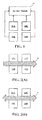
- FIG. 1 illustrates the wireless remote control system in the first embodiment according to the invention.
- the system in this embodiment includes a remote controller (not shown), four detectors (14A ⁇ 14D) arranged substantially as a rectangle on a plane, and a decision module 16.
- the remote controller is used for emitting a wireless signal.
- the wireless signal can be an ultrasonic signal.
- the four detectors can also be arranged substantially as a rhombus.
- the detectors 14A ⁇ 14D detect the wireless signal emitted by the remote controller and respectively generate a detecting result. Since the positions of the detectors 14A ⁇ 14D relative to the remote controller are different, the detectors 14A ⁇ 14D generate different detecting results when the remote controller moves. Taking the detector 14A as an example, when the remote controller is moving toward the detector 14A, the frequency detected by the detector 14A ( f 1 ) is higher than the frequency of the wireless signal emitted by the remote controller ( f 0 ), which is unknown to the decision module. When the remote controller is moving away from the detector 14A, f 1 is lower than f 0 . Similarly, when the remote controller is moving toward the detector 14B, the frequency detected by the detector 14B (f 2 ) is higher than f 0 . When the remote controller is moving away from the detector 14B, f 2 is lower than f 0 .
- the decision module 16 can determine the movement pattern of the remote controller (i.e., the gesture of the user) by calculating the differences between the detected frequencies. For instance, if the remote controller moves along the arrow A shown in FIG. 2(A) , when the remote controller is moving away from the detector 14A but close to the detector 14C, the frequency detected by the detector 14A ( f 1 ) is lower than f 0 , and the frequency detected by the detector 14C ( f 3 ) is higher than f 0 . During this period, the result of subtracting f 3 from f 1 is negative.
- the decision module 16 can determine if the remote controller moves along the specific direction or along a reverse direction opposite to the specific direction based on the frequency difference between the detecting results of the two detectors.
- the frequency difference between the detectors 14A and 14C is periodical and alternatively changes between positive and negative values.
- the frequency difference between the detectors 14B and 14D is also periodic. According to these results, the decision module 16 can judge that the user moves the remote controller along the horizontal direction shown as the arrow B.
- the decision module 16 judges the movement pattern of the remote controller based on at least one frequency difference between the detecting results.
- the decision module 16 according to the invention can calculate the frequency differences between the detecting results without the knowledge of f 0 . Therefore, the infrared transmitter and infrared receiver for synchronizing f 0 in prior arts are unnecessary in the wireless remote control system according to the invention.
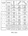
- the tables shown in FIG. 3(A) and FIG. 3(B) further illustrate the characteristics of the frequency differences or sum under the conditions when the remote controller moves horizontally, vertically, obliquely (including from-right-to-left and from-left-to-right), circularly (including clockwise and counterclockwise), or back and forth.
- the symbols f 1 ⁇ f 4 respectively represent the frequency detected at the detectors 14A ⁇ 14D.
- the decision module 16 can judge the movement pattern of the remote controller in the space. Practically, the decision module 16 can judge the movement pattern of the remote controller based on whether the frequency differences are periodical signals or combinations of plural periodical signals.
- the decision module 16 can optionally generate a control signal transfer the control signal to a subsequent electronic or mechanical system.
- the decision module 16 can generate different control signals.
- the control signal can be used to turn on/off a television, adjust the volume of the television, select the channel of the television, or adjust the temperature of an air conditioner.
- the remote controller can be as simple as including only one battery and an oscillating circuit for generating the wireless signal. Therefore, both the cost and power consumption of the remote controller are considerably low.
- the size of the remote controller is quite small and can be integrated in an ornament, such as a ring, or personal belongings (for instance, a mobile phone, a watch, or a pen).
- the detectors 14A ⁇ 14D can include frequency detection circuits for determining the frequency of the wireless signal based on the number of voltage transitions of the wireless signal.
- the decision module 16 can include a circuit or software for analyzing the spectrum of the frequency differences between two detectors. In this spectrum if the value at some frequency is above a certain threshold, the decision module 16 can decide that the remote controller has some obvious periodic movement along the direction of those two detectors.
- the number of detectors in wireless remote control systems according to the invention can be different from that in this embodiment. For instance, using one, two, three, six, eight, or more detectors is also possible.
- a combination of two or more movement patterns can be applied in sequence to make up more commands, for instance, clockwise circular motion followed by top-down motion.
- the decision module 16 can determine the movement pattern only when at least one detecting result among the detecting results conforms to a predetermined frequency limitation. By excluding signals with frequencies lower than a lowest limit, low frequency noises can be filtered out; this can also be a limitation for judging whether the wireless signal emitted by the remote controller exists. By excluding signals with frequencies higher than an upper limit, high frequency noises can be filtered out from the detected signals. In other words, the decision module 16 can be designed as only operating for stable wireless signals in a particular frequency band.
- the frequencies respectively detected by the detectors 14A ⁇ 14D are linearly related to the velocities along corresponding directions of the remote controller. Accordingly, the frequency difference between two detecting results is also directly proportional to the velocity difference between the moving velocities of the remote controller respectively relative to the two detectors. If the wireless remote control system according to the invention includes two detectors disposed along a specific direction, the decision module 16 can estimate the velocity of the remote controller along the specific direction based on the frequency difference between the detector outputs.
- the decision module 16 can estimate the velocity and moving direction of the remote controller according to the detecting results of the detectors 14A ⁇ 14D, the decision module 16 can further integrate the moving velocity in time domain, so as to determine and record a trajectory of the remote controller in the space.
- the manager/designer of the wireless remote control system according to the invention can further define more commands corresponding to more complicated gestures. For example, can input icons, symbols, numbers, letters in alphabets, or Chinese characters via the remote controller.
- a multiple access modulation can be performed on the wireless signal before the wireless signal is emitted from the remote controller.
- the multiple access modulation for example, can be a time division multiple access (TDMA) modulation, a code division multiple access (CDMA) modulation, or a frequency division multiple access (FDMA) modulation.
- TDMA time division multiple access
- CDMA code division multiple access
- FDMA frequency division multiple access
- the decision module 16 can include a demodulating unit for demodulating the wireless signal and determining identification information of the remote controller.
- the designer or manager of the wireless remote control system can define ten frequencies (e.g. 36 KHz, 37 KHz, 38 KHz ..., and 45 KHz); every remote controller can select three frequencies therefrom and emit signals of the three frequencies. There would be about 1,200 frequency combinations.
- the decision module 16 can also distinguish different remote controllers. With this arrangement, the identification of the user can be determined by the decision module. This user identification information can facilitate further control of the user commands, e.g., young children are not allowed to enter commands that will lead them to viewing of improper content.
- Another embodiment according to the invention is a wireless remote control system including a remote controller, a detector, and a decision module. Based on at least one frequency difference between the detecting results detected at different times, the decision module in this embodiment determines the movement pattern of the remote controller and generates a control signal according to the movement pattern.
- the detector detects a higher frequency. Assuming the detecting result detected at a first time instant is a first frequency and the detecting result detected at a second time instant is a second frequency, the decision module can determine if the remote controller moves back and forth along the direction perpendicular to the wall based on the frequency difference between the first frequency and the second frequency.
- Another embodiment according to the invention is also a wireless remote control system including a remote controller, a detector, and a decision module.
- the detector in this embodiment is used for detecting the frequency of the wireless signal emitted by the remote controller.
- the decision module generates a control signal according to a time pattern of the frequency, which is related to the movement pattern of the remote controller.
- a forward-backward motion of the remote controller is corresponding to a high-low time pattern of the detected frequency. For instance, three periods of forward-backward motion is deemed a long "dash" and one period of forward-backward motion is deemed a short "dot.”
- This Morse-code-like combination can constitute several different commands recognized by the decision module using only one detector. It should be noted that the decision module in this embodiment does not have to know the frequency of the wireless signal emitted by the remote controller ( f 0 ), either.
- the wireless remote controller according to the invention has many advantages, such as small size, low cost, low power consumption, and easy to use. Further, the wireless remote control system according to the invention can be widely used in various fields that need wireless remote control.
- the detecting circuit in the invention has lower operation frequencies. Hence, not only the remote controller but also the detecting circuit according to the invention has the advantages of low cost and low power consumption.
Landscapes
- Engineering & Computer Science (AREA)
- General Engineering & Computer Science (AREA)
- Theoretical Computer Science (AREA)
- Physics & Mathematics (AREA)
- General Physics & Mathematics (AREA)
- Human Computer Interaction (AREA)
- Radar, Positioning & Navigation (AREA)
- Remote Sensing (AREA)
- Computer Networks & Wireless Communication (AREA)
- Selective Calling Equipment (AREA)
- Transceivers (AREA)
Abstract
Description
- The present invention relates to remote control systems. In particular, the present invention relates to wireless remote control systems that determines control signals based on users' gestures.
- Wireless control of electrical/electronic devices is becoming indispensable. For instance, garage door opening, audio/video equipment (TV) control, air conditioner control, projector control, wireless mouse, and so on. Wireless controllers provide the convenience that saves users from walking to the devices that they want to control. Most commercial wireless controllers at the present time are based on radio-frequency (RF) or infrared signals to communicate the intended commands to the controlled devices.
- Practically, besides RF and infrared signals, ultrasonic signals can also be used for remote wireless control purpose.
U.S. patent 4,578,674 discloses a wireless cursor control using a position device (mouse). In this patent, two detectors disposed at the computer side detect how a wireless mouse moves based the ultrasonic signal emitted by the mouse; a cursor on a display panel is accordingly controlled. - Because of the Doppler effect, the frequencies detected by the two detectors (represented as f1 and f2 ) at the computer side are different from the original frequency of the ultrasonic signal emitted by the mouse (represented as f0 ). The microprocessor at the computer side first calculates the difference between f1 and f0 and the difference between f2 and f0 . According to the two differences, the microprocessor estimates the direction and velocity of the mouse motion relative to the detectors. Then the patent calculates the movement of the position device from an initial location and moves the cursor on the display accordingly.
- The disadvantage of the above idea is that the calculation is highly related to the reference frequency of the ultrasonic signal emitted by the mouse (f0 ). More specifically, the calculation cannot be done without knowing the value of f0 . Hence, in
U.S. patent 4,578,674 , an infrared emitter for providing a reference signal is set at the computer side. Correspondingly, an infrared receiver for receiving the reference signal is set on the position device (mouse). A continuous-wave signal with the exact frequency f0 is carried on an infrared signal through modulation. At the position device, an infrared receiver and a demodulator can recover that signal for generation of the ultrasonic signal with frequency f0 . In other words, through this reference signal, the computer side controls the frequency of the ultrasonic signal emitted by the mouse (f0 ). However, including an infrared receiver at the remote control device increases both its size and power consumption, rendering such control mechanism undesirable. -
U.S. patent 4,654,648 also utilizes acoustic signal emitted from the controller and measure the time difference between signals arriving at several different acoustic receivers. Using triangulation, the patent can determine the position of the controller. This patent does not teach a wireless remote control based on Doppler effect induced from the motion of the controller. -
U.S. patent 5,999,167 teaches another wireless cursor control system based on ultrasonic signal. The ultrasonic signal is emitted from the base unit and the remote controller is equipped with multiple ultrasonic receivers. The phases of the received ultrasonic signals are captured and compared to determine the angular orientation of the remote unit and therefore cursor movement on the display can be accordingly controlled according to said detected orientation change. - U.S. patent application
US2007/0115252 is based onUS patent 5,999,167 and includes an extra sensitivity adjuster to extend the application ofUS patent 5,999,167 to the cases when the remote controller is at a far distance away from the base unit. -
U.S. patent 6,504,526 presents a wireless pointing device based on infrared signal. Multiple receivers receive infrared pulse-train signal from a transmitter. As the remote unit is moved, wavefront will arrive at different receivers at different times. By detecting the peaks in the received signal's amplitude (or envelope) and compare their arrival times, movement along a particular direction of the remote control unit can be detected. - In summary most prior arts use either IR or RF signals for remote control or cursor control. Of those that use ultrasonic signal, most detect the arrival times of the signal or the phases of the signals. Only
U.S. patent 4,578,674 detects the frequencies of the received ultrasonic signals. However, in order to calculate the absolute frequency difference, and thus absolute velocity of the transmitter,U.S. patent 4,578,674 sends a reference signal with frequency f0 to the remote controller. do not detect the frequency of the received ultrasonic signals. This requires an extra pair of infrared transmitter and receiver, which necessitates more cost and power consumption. - The wireless remote control system according to the invention also operates based on the concept of the Doppler effect induced by the movement of a remote controller, which emits a wireless signal consisting of tone(s) of one frequency or a group of several frequencies. However, the host side in the invention does not have to know the exact frequency of the wireless signal emitted by said remote controller. Accordingly, the infrared emitter and infrared receiver in
U.S. patent 4,578,674 can be omitted. - One embodiment according to the invention is a wireless remote control system including a remote controller, a plurality of detectors, and a decision module. The detectors are used for detecting a wireless signal emitted by the remote controller and respectively generating a detecting result. Based on at least one frequency difference between the detecting results, the decision module determines a movement pattern of the remote controller and generates a control signal intended by the user holding the remote controller accordingly.
- Another embodiment according to the invention is a wireless remote control system including a remote controller, a detector, and a decision module. The detector is used for detecting the wireless signal emitted by the remote controller and generating a detecting result. Based on at least one frequency difference between the detecting results detected at different times, the decision module determines a movement pattern of the remote controller and generates a control signal intended by the user holding the remote controller accordingly.
- Another embodiment according to the invention is also a wireless remote control system including a remote controller, a detector, and a decision module. The detector in this embodiment is used for detecting the frequency of the wireless signal emitted by the remote controller. The decision module generates a control signal according to a time pattern of the frequency.
- The wireless remote controller according to the invention has many advantages, such as small size, low cost, low power consumption, and easy to use. Further, the wireless remote control system can be widely used in various fields that need wireless remote controls. The advantage and spirit of the invention may be understood by the following recitations together with the appended drawings.
-
-
FIG. 1 illustrates the wireless remote control system in the first embodiment according to the invention. -
FIG. 2(A) and FIG. 2(B) show examples of the movement patterns of the remote controller relative to the detectors. - The tables in
FIG. 3(A) andFIG. 3(B) illustrate the characteristics of the frequency differences under different movement patterns. - Frequency shift induced by the Doppler effect of a wireless signal is the basis for detecting the movement pattern made by a remote controller in the wireless remote control system according to the invention. As known by those skilled in the art, when there is a relative movement a signal source and an observer, the relationship between the detected frequency of the signal (f) and the original frequency (f0 ) at the transmitting end is:

- In this equation, v represents the speed of the signal, vs represents the moving velocity of the signal source along the direction from the observer to the source, and vr represents the velocity of the observer along said direction. If both the location of the observer and the frequency of the emitted signal source are fixed, then f0 and vr are constants. If the signal source is a remote controller hold by a user, vs is related to the motion of the user's hand. Generally, the speed of movement by human hands is roughly in the range of 1m/s ∼ 3m/s, which is much lower than the speed of sound waves. Therefore, in the case of ultrasonic signal the above equation can be modified as:
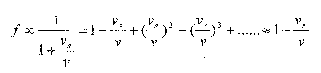
- As shown in this equation, the observed frequency (f) and the velocity of the sound source along a direction (vs ) are approximately linearly related. Based on this relationship, the wireless remote control system according to the invention can continuously estimate and monitor the velocity of a remote controller and thus determine its movement pattern.
-
FIG. 1 illustrates the wireless remote control system in the first embodiment according to the invention. The system in this embodiment includes a remote controller (not shown), four detectors (14A∼14D) arranged substantially as a rectangle on a plane, and adecision module 16. The remote controller is used for emitting a wireless signal. According to the invention, the wireless signal can be an ultrasonic signal. In actual applications, the four detectors can also be arranged substantially as a rhombus. - The
detectors 14A ∼ 14D detect the wireless signal emitted by the remote controller and respectively generate a detecting result. Since the positions of thedetectors 14A ∼ 14D relative to the remote controller are different, thedetectors 14A ∼ 14D generate different detecting results when the remote controller moves. Taking thedetector 14A as an example, when the remote controller is moving toward thedetector 14A, the frequency detected by thedetector 14A (f1 ) is higher than the frequency of the wireless signal emitted by the remote controller (f0 ), which is unknown to the decision module. When the remote controller is moving away from thedetector 14A, f1 is lower than f0 . Similarly, when the remote controller is moving toward thedetector 14B, the frequency detected by thedetector 14B (f2) is higher than f0 . When the remote controller is moving away from thedetector 14B, f2 is lower than f0 . - Based on the relative relationship of the frequencies, the
decision module 16 can determine the movement pattern of the remote controller (i.e., the gesture of the user) by calculating the differences between the detected frequencies. For instance, if the remote controller moves along the arrow A shown inFIG. 2(A) , when the remote controller is moving away from thedetector 14A but close to thedetector 14C, the frequency detected by thedetector 14A (f1 ) is lower than f0 , and the frequency detected by thedetector 14C (f3 ) is higher than f0 . During this period, the result of subtracting f3 from f1 is negative. On the contrary, if the remote controller moves along the direction opposite to the arrow A, when the remote controller is moving away from thedetector 14C but close to thedetector 14A, f1 is higher than f0 , and f3 is lower than f 0. In this period, the result of subtracting f3 from f1 is positive. - It can be seen that if the wireless remote control system includes two detectors spaced apart along a specific direction, the
decision module 16 can determine if the remote controller moves along the specific direction or along a reverse direction opposite to the specific direction based on the frequency difference between the detecting results of the two detectors. - Further, when the remote controller moves repeatedly along the arrow B shown in
FIG. 2(B) , the frequency difference between thedetectors detectors decision module 16 can judge that the user moves the remote controller along the horizontal direction shown as the arrow B. - As described above, the
decision module 16 judges the movement pattern of the remote controller based on at least one frequency difference between the detecting results. In other words, thedecision module 16 according to the invention can calculate the frequency differences between the detecting results without the knowledge of f0. Therefore, the infrared transmitter and infrared receiver for synchronizing f0 in prior arts are unnecessary in the wireless remote control system according to the invention. - The tables shown in
FIG. 3(A) andFIG. 3(B) further illustrate the characteristics of the frequency differences or sum under the conditions when the remote controller moves horizontally, vertically, obliquely (including from-right-to-left and from-left-to-right), circularly (including clockwise and counterclockwise), or back and forth. The symbols f1 ∼ f4 respectively represent the frequency detected at thedetectors 14A ∼ 14D. Based on the change patterns of the frequency differences in time domain, thedecision module 16 can judge the movement pattern of the remote controller in the space. Practically, thedecision module 16 can judge the movement pattern of the remote controller based on whether the frequency differences are periodical signals or combinations of plural periodical signals. - After determining the movement pattern of the remote controller, the
decision module 16 can optionally generate a control signal transfer the control signal to a subsequent electronic or mechanical system. Corresponding to different movement patterns, thedecision module 16 can generate different control signals. For instance, the control signal can be used to turn on/off a television, adjust the volume of the television, select the channel of the television, or adjust the temperature of an air conditioner. - As shown in the examples mentioned in
FIG. 3(A) andFIG. 3(B) , users can give various commands by moving the remote controller with simple gestures. In actual applications, the remote controller can be as simple as including only one battery and an oscillating circuit for generating the wireless signal. Therefore, both the cost and power consumption of the remote controller are considerably low. Moreover, the size of the remote controller is quite small and can be integrated in an ornament, such as a ring, or personal belongings (for instance, a mobile phone, a watch, or a pen). - Practically, the
detectors 14A ∼ 14D can include frequency detection circuits for determining the frequency of the wireless signal based on the number of voltage transitions of the wireless signal. Thedecision module 16 can include a circuit or software for analyzing the spectrum of the frequency differences between two detectors. In this spectrum if the value at some frequency is above a certain threshold, thedecision module 16 can decide that the remote controller has some obvious periodic movement along the direction of those two detectors. Moreover, the number of detectors in wireless remote control systems according to the invention can be different from that in this embodiment. For instance, using one, two, three, six, eight, or more detectors is also possible. Furthermore, if there is a need for more than seven commands inFIG. 3 , a combination of two or more movement patterns can be applied in sequence to make up more commands, for instance, clockwise circular motion followed by top-down motion. - In practical applications, the
decision module 16 can determine the movement pattern only when at least one detecting result among the detecting results conforms to a predetermined frequency limitation. By excluding signals with frequencies lower than a lowest limit, low frequency noises can be filtered out; this can also be a limitation for judging whether the wireless signal emitted by the remote controller exists. By excluding signals with frequencies higher than an upper limit, high frequency noises can be filtered out from the detected signals. In other words, thedecision module 16 can be designed as only operating for stable wireless signals in a particular frequency band. - Furthermore, as described above, the frequencies respectively detected by the
detectors 14A ∼ 14D are linearly related to the velocities along corresponding directions of the remote controller. Accordingly, the frequency difference between two detecting results is also directly proportional to the velocity difference between the moving velocities of the remote controller respectively relative to the two detectors. If the wireless remote control system according to the invention includes two detectors disposed along a specific direction, thedecision module 16 can estimate the velocity of the remote controller along the specific direction based on the frequency difference between the detector outputs. - Since the
decision module 16 can estimate the velocity and moving direction of the remote controller according to the detecting results of thedetectors 14A ∼ 14D, thedecision module 16 can further integrate the moving velocity in time domain, so as to determine and record a trajectory of the remote controller in the space. By doing this, the manager/designer of the wireless remote control system according to the invention can further define more commands corresponding to more complicated gestures. For example, can input icons, symbols, numbers, letters in alphabets, or Chinese characters via the remote controller. - In practical applications, if there is a need of distinguishing plural users or plural apparatuses to be controlled, a multiple access modulation can be performed on the wireless signal before the wireless signal is emitted from the remote controller. The multiple access modulation, for example, can be a time division multiple access (TDMA) modulation, a code division multiple access (CDMA) modulation, or a frequency division multiple access (FDMA) modulation. Thereby, identification information can be added into the wireless signal.
- Correspondingly, the
decision module 16 can include a demodulating unit for demodulating the wireless signal and determining identification information of the remote controller. For instance, the designer or manager of the wireless remote control system can define ten frequencies (e.g. 36 KHz, 37 KHz, 38 KHz ..., and 45 KHz); every remote controller can select three frequencies therefrom and emit signals of the three frequencies. There would be about 1,200 frequency combinations. According to the frequency components of a wireless signal, thedecision module 16 can also distinguish different remote controllers. With this arrangement, the identification of the user can be determined by the decision module. This user identification information can facilitate further control of the user commands, e.g., young children are not allowed to enter commands that will lead them to viewing of improper content. - The idea of the invention can also be applied in the condition with only one detector. Another embodiment according to the invention is a wireless remote control system including a remote controller, a detector, and a decision module. Based on at least one frequency difference between the detecting results detected at different times, the decision module in this embodiment determines the movement pattern of the remote controller and generates a control signal according to the movement pattern.
- Taking the condition when the detector is set on a certain wall as an example, when the remote controller has a moving vector along the direction perpendicular to and toward the wall (corresponding to the gesture in the right column in
FIG. 3(B) ), the detector detects a higher frequency. Assuming the detecting result detected at a first time instant is a first frequency and the detecting result detected at a second time instant is a second frequency, the decision module can determine if the remote controller moves back and forth along the direction perpendicular to the wall based on the frequency difference between the first frequency and the second frequency. - Another embodiment according to the invention is also a wireless remote control system including a remote controller, a detector, and a decision module. The detector in this embodiment is used for detecting the frequency of the wireless signal emitted by the remote controller. The decision module generates a control signal according to a time pattern of the frequency, which is related to the movement pattern of the remote controller. As explained above, a forward-backward motion of the remote controller is corresponding to a high-low time pattern of the detected frequency. For instance, three periods of forward-backward motion is deemed a long "dash" and one period of forward-backward motion is deemed a short "dot." This Morse-code-like combination can constitute several different commands recognized by the decision module using only one detector. It should be noted that the decision module in this embodiment does not have to know the frequency of the wireless signal emitted by the remote controller (f0 ), either.
- As described above, the wireless remote controller according to the invention has many advantages, such as small size, low cost, low power consumption, and easy to use. Further, the wireless remote control system according to the invention can be widely used in various fields that need wireless remote control.
- Compared with most remote control systems utilizing infrared or RF signals at the present time, the detecting circuit in the invention has lower operation frequencies. Hence, not only the remote controller but also the detecting circuit according to the invention has the advantages of low cost and low power consumption.
- With the example and explanations above, the features and spirits of the invention will be hopefully well described. Those skilled in the art will readily observe that numerous modifications and alterations of the device may be made while retaining the teaching of the invention. Accordingly, the above disclosure should be construed as limited only by the metes and bounds of the appended claims.
Claims (17)
- A wireless remote control system, comprising:a remote controller for emitting a wireless signal;a plurality of detectors (14A∼14D) for detecting the wireless signal andrespectively generating a detecting result; anda decision module (16) electrically connected to the detectors (14A∼14D), based on at least one frequency difference between the detecting results, the decision module (16) determining a movement pattern of the remote controller and generating a control signal according to the movement pattern.
- The wireless remote control system of claim 1, wherein the wireless signal is an ultrasonic signal.
- The wireless remote control system of claim 1, wherein the plural detectors (14A∼14D) comprise a first detector and a second detector disposed along a specific direction, the detecting result of the first detector is a first frequency, the detecting result of the second detector is a second frequency, based on the frequency difference between the first frequency and the second frequency, the decision module (16) determines if the remote controller moves along the specific direction or along a reverse direction opposite to the specific direction or determines a moving speed thereof.
- The wireless remote control system of claim 1, wherein the decision module (16) determines the movement pattern of the remote controller based on a change pattern of the frequency difference in time domain.
- The wireless remote control system of claim 4, wherein the decision module (16) determines the movement pattern of the remote controller based on whether the frequency difference follows a periodical pattern or a combination of plural periodical patterns.
- The wireless remote control system of claim 1, wherein corresponding to conditions that the remote controller moves horizontally, vertically, obliquely, circularly, or back and forth, the control signal is different.
- The wireless remote control system of claim 1, wherein the decision module (16) further determines and records a movement trajectory of the remote controller based on the frequency difference.
- The wireless remote control system of claim 7, wherein the decision module (16) determines a moving velocity and a moving direction of the remote controller based on the frequency difference and determines the movement trajectory according to the moving velocity and the moving direction.
- The wireless remote control system of claim 1, wherein a multiple access modulation is performed on the wireless signal before the wireless signal is emitted from the remote controller; the decision module (16) comprises a demodulating unit for demodulating the wireless signal and determines identification information of the remote controller.
- The wireless remote control system of claim 9, wherein the multiple access modulation is a time division multiple access (TDMA) modulation, a code division multiple access (CDMA) modulation, or a frequency division multiple access (FDMA) modulation.
- The wireless remote control system of claim 1, wherein only when at least one detecting result among the detecting results conforms to a predetermined frequency limitation, the decision module (16) determines the movement pattern based on the at least one frequency difference.
- The wireless remote control system of claim 1, wherein the remote controller comprises a battery and an oscillating circuit for generating the wireless signal.
- The wireless remote control system of claim 1, wherein each of the detectors (14A∼14D) respectively comprises a frequency deciding circuit for determining a frequency of the wireless signal based on the number of transitions of the wireless signal.
- A wireless remote control system, comprising:a remote controller for emitting a wireless signal;a detector (14A, 12B, 12C, or 14D) for detecting the wireless signal andgenerating a detecting result; anda decision module (16) electrically connected to the detector (14A, 12B, 12C, or 14D), based on at least one frequency difference between the detecting results detected at different time instants, the decision module (16) determining a movement pattern of the remote controller and generating a control signal according to the movement pattern.
- The wireless remote control system of claim 14, wherein the wireless signal is an ultrasonic signal.
- The wireless remote control system of claim 14, wherein the detecting result detected at a first time instant is a first frequency, the detecting result detected at a second time instant is a second frequency, based on the frequency difference between the first frequency and the second frequency, the decision module (16) determines if the remote controller moves along a specific direction or along a reverse direction opposite to the specific direction or determines a moving speed thereof.
- A wireless remote control system, comprising:a remote controller for emitting a wireless signal;a detector (14A, 12B, 12C, or 14D) for detecting a frequency the wireless signal; anda decision module (16) electrically connected to the detector, for generating a control signal according to a time pattern of the frequency.
Applications Claiming Priority (2)
| Application Number | Priority Date | Filing Date | Title |
|---|---|---|---|
| TW98134245 | 2009-10-09 | ||
| TW098139771A TWI423078B (en) | 2009-10-09 | 2009-11-23 | Wireless remote control system |
Publications (3)
| Publication Number | Publication Date |
|---|---|
| EP2323013A2 true EP2323013A2 (en) | 2011-05-18 |
| EP2323013A3 EP2323013A3 (en) | 2011-06-08 |
| EP2323013B1 EP2323013B1 (en) | 2014-08-27 |
Family
ID=42583986
Family Applications (1)
| Application Number | Title | Priority Date | Filing Date |
|---|---|---|---|
| EP10154768.5A Active EP2323013B1 (en) | 2009-10-09 | 2010-02-26 | Wireless remote control system |
Country Status (2)
| Country | Link |
|---|---|
| EP (1) | EP2323013B1 (en) |
| TW (1) | TWI423078B (en) |
Families Citing this family (3)
| Publication number | Priority date | Publication date | Assignee | Title |
|---|---|---|---|---|
| TWI492195B (en) * | 2012-04-26 | 2015-07-11 | Bold Team Man Ltd | Remote control method and remote control |
| TWI639327B (en) | 2017-05-18 | 2018-10-21 | 正修學校財團法人正修科技大學 | A wireless remote control system for smart mobile devices using moss codes |
| CN109559497A (en) | 2017-09-27 | 2019-04-02 | 朗德万斯公司 | Utilize the method for remote control control electronic device, remote controler and system |
Family Cites Families (6)
| Publication number | Priority date | Publication date | Assignee | Title |
|---|---|---|---|---|
| US4578674A (en) * | 1983-04-20 | 1986-03-25 | International Business Machines Corporation | Method and apparatus for wireless cursor position control |
| GB2388749B (en) * | 2002-05-17 | 2005-11-16 | Nec Technologies | Method and system for determining movement characteristics of a mobile radio telecommunications device |
| TW200512652A (en) * | 2003-09-26 | 2005-04-01 | Jia-Zhang Hu | Cursor simulator using limbs to control cursor and method for simulating the same |
| GB2408337B (en) * | 2003-11-21 | 2005-11-23 | Marc Zuta | Graphic input device and method |
| CN1942850A (en) * | 2004-01-30 | 2007-04-04 | 皇家飞利浦电子股份有限公司 | 3-D cursor control system |
| TWI334559B (en) * | 2007-08-28 | 2010-12-11 | Ind Tech Res Inst | Interactive pointing device |
-
2009
- 2009-11-23 TW TW098139771A patent/TWI423078B/en not_active IP Right Cessation
-
2010
- 2010-02-26 EP EP10154768.5A patent/EP2323013B1/en active Active
Also Published As
| Publication number | Publication date |
|---|---|
| TW201113766A (en) | 2011-04-16 |
| TWI423078B (en) | 2014-01-11 |
| EP2323013B1 (en) | 2014-08-27 |
| EP2323013A3 (en) | 2011-06-08 |
Similar Documents
| Publication | Publication Date | Title |
|---|---|---|
| US8305251B2 (en) | Wireless remote control system | |
| EP4286996A2 (en) | Detecting a frame-of-reference change in a smart-device-based radar system | |
| US9134800B2 (en) | Gesture input device and gesture input method | |
| US8436813B2 (en) | Pointing device and method and pointer display apparatus and method | |
| CN103279223B (en) | A kind of method of touch information feedback, equipment and system | |
| US20170083164A1 (en) | Detecting touch input provided by signal transmitting stylus | |
| EP2860611A1 (en) | User interface method and apparatus based on spatial location recognition | |
| US20160246390A1 (en) | Active pen with bidirectional communication | |
| US9949082B2 (en) | Mobile terminal device, location search method, and computer-readable recording medium | |
| KR20230044040A (en) | Controlling electronic devices and displaying information based on wireless ranging | |
| KR101984737B1 (en) | Touch system comprising optical touch panel and touch pen, and method of controlling interference optical signal in touch system | |
| US20140152537A1 (en) | Method and device for identifying contactless gestures | |
| US9949107B2 (en) | Method and system for detecting an input to a device | |
| Zhang et al. | Tap-to-pair: associating wireless devices with synchronous tapping | |
| CN106468780A (en) | Portable device and related vibration detection method | |
| KR20150145857A (en) | Electronic apparatus and method for pairing in electronic apparatus | |
| KR101698087B1 (en) | Mobile terminal and control method thereof | |
| EP2323013B1 (en) | Wireless remote control system | |
| JP2011217324A (en) | Instrument operating apparatus | |
| CN112654955B (en) | Detection of the positioning of the pen relative to the electronic device | |
| CN110031860A (en) | Laser distance measurement method, device and mobile terminal | |
| US9285901B2 (en) | Electronic device for recognizing asynchronous digital pen and recognizing method thereof | |
| JP2013257775A (en) | Touch sensor | |
| CN102117536A (en) | Wireless remote control system | |
| US20080158435A1 (en) | Remote control posittioning system |
Legal Events
| Date | Code | Title | Description |
|---|---|---|---|
| PUAI | Public reference made under article 153(3) epc to a published international application that has entered the european phase |
Free format text: ORIGINAL CODE: 0009012 |
|
| PUAL | Search report despatched |
Free format text: ORIGINAL CODE: 0009013 |
|
| 17P | Request for examination filed |
Effective date: 20100226 |
|
| AK | Designated contracting states |
Kind code of ref document: A2 Designated state(s): AT BE BG CH CY CZ DE DK EE ES FI FR GB GR HR HU IE IS IT LI LT LU LV MC MK MT NL NO PL PT RO SE SI SK SM TR |
|
| AX | Request for extension of the european patent |
Extension state: AL BA RS |
|
| AK | Designated contracting states |
Kind code of ref document: A3 Designated state(s): AT BE BG CH CY CZ DE DK EE ES FI FR GB GR HR HU IE IS IT LI LT LU LV MC MK MT NL NO PL PT RO SE SI SK SM TR |
|
| AX | Request for extension of the european patent |
Extension state: AL BA RS |
|
| RIC1 | Information provided on ipc code assigned before grant |
Ipc: G01S 11/14 20060101ALI20110429BHEP Ipc: G06F 3/033 20060101ALI20110429BHEP Ipc: G06F 3/038 20060101ALI20110429BHEP Ipc: G08C 17/02 20060101ALI20110429BHEP Ipc: G06F 3/01 20060101AFI20110315BHEP |
|
| RIC1 | Information provided on ipc code assigned before grant |
Ipc: G06F 3/0346 20130101AFI20130513BHEP |
|
| 17Q | First examination report despatched |
Effective date: 20130705 |
|
| REG | Reference to a national code |
Ref country code: DE Ref legal event code: R079 Ref document number: 602010018500 Country of ref document: DE Free format text: PREVIOUS MAIN CLASS: G06F0003010000 Ipc: G01S0011140000 |
|
| GRAP | Despatch of communication of intention to grant a patent |
Free format text: ORIGINAL CODE: EPIDOSNIGR1 |
|
| RIC1 | Information provided on ipc code assigned before grant |
Ipc: G08C 17/00 20060101ALI20140219BHEP Ipc: G06F 3/038 20130101ALI20140219BHEP Ipc: G01S 11/14 20060101AFI20140219BHEP Ipc: G06F 3/01 20060101ALI20140219BHEP |
|
| INTG | Intention to grant announced |
Effective date: 20140327 |
|
| GRAS | Grant fee paid |
Free format text: ORIGINAL CODE: EPIDOSNIGR3 |
|
| GRAA | (expected) grant |
Free format text: ORIGINAL CODE: 0009210 |
|
| AK | Designated contracting states |
Kind code of ref document: B1 Designated state(s): AT BE BG CH CY CZ DE DK EE ES FI FR GB GR HR HU IE IS IT LI LT LU LV MC MK MT NL NO PL PT RO SE SI SK SM TR |
|
| REG | Reference to a national code |
Ref country code: GB Ref legal event code: FG4D |
|
| REG | Reference to a national code |
Ref country code: CH Ref legal event code: EP |
|
| REG | Reference to a national code |
Ref country code: AT Ref legal event code: REF Ref document number: 684774 Country of ref document: AT Kind code of ref document: T Effective date: 20140915 |
|
| REG | Reference to a national code |
Ref country code: IE Ref legal event code: FG4D |
|
| REG | Reference to a national code |
Ref country code: DE Ref legal event code: R096 Ref document number: 602010018500 Country of ref document: DE Effective date: 20141009 |
|
| REG | Reference to a national code |
Ref country code: AT Ref legal event code: MK05 Ref document number: 684774 Country of ref document: AT Kind code of ref document: T Effective date: 20140827 |
|
| REG | Reference to a national code |
Ref country code: LT Ref legal event code: MG4D |
|
| REG | Reference to a national code |
Ref country code: NL Ref legal event code: VDEP Effective date: 20140827 |
|
| PG25 | Lapsed in a contracting state [announced via postgrant information from national office to epo] |
Ref country code: FI Free format text: LAPSE BECAUSE OF FAILURE TO SUBMIT A TRANSLATION OF THE DESCRIPTION OR TO PAY THE FEE WITHIN THE PRESCRIBED TIME-LIMIT Effective date: 20140827 Ref country code: BG Free format text: LAPSE BECAUSE OF FAILURE TO SUBMIT A TRANSLATION OF THE DESCRIPTION OR TO PAY THE FEE WITHIN THE PRESCRIBED TIME-LIMIT Effective date: 20141127 Ref country code: SE Free format text: LAPSE BECAUSE OF FAILURE TO SUBMIT A TRANSLATION OF THE DESCRIPTION OR TO PAY THE FEE WITHIN THE PRESCRIBED TIME-LIMIT Effective date: 20140827 Ref country code: PT Free format text: LAPSE BECAUSE OF FAILURE TO SUBMIT A TRANSLATION OF THE DESCRIPTION OR TO PAY THE FEE WITHIN THE PRESCRIBED TIME-LIMIT Effective date: 20141229 Ref country code: NO Free format text: LAPSE BECAUSE OF FAILURE TO SUBMIT A TRANSLATION OF THE DESCRIPTION OR TO PAY THE FEE WITHIN THE PRESCRIBED TIME-LIMIT Effective date: 20141127 Ref country code: LT Free format text: LAPSE BECAUSE OF FAILURE TO SUBMIT A TRANSLATION OF THE DESCRIPTION OR TO PAY THE FEE WITHIN THE PRESCRIBED TIME-LIMIT Effective date: 20140827 Ref country code: ES Free format text: LAPSE BECAUSE OF FAILURE TO SUBMIT A TRANSLATION OF THE DESCRIPTION OR TO PAY THE FEE WITHIN THE PRESCRIBED TIME-LIMIT Effective date: 20140827 Ref country code: GR Free format text: LAPSE BECAUSE OF FAILURE TO SUBMIT A TRANSLATION OF THE DESCRIPTION OR TO PAY THE FEE WITHIN THE PRESCRIBED TIME-LIMIT Effective date: 20141128 |
|
| PG25 | Lapsed in a contracting state [announced via postgrant information from national office to epo] |
Ref country code: AT Free format text: LAPSE BECAUSE OF FAILURE TO SUBMIT A TRANSLATION OF THE DESCRIPTION OR TO PAY THE FEE WITHIN THE PRESCRIBED TIME-LIMIT Effective date: 20140827 Ref country code: HR Free format text: LAPSE BECAUSE OF FAILURE TO SUBMIT A TRANSLATION OF THE DESCRIPTION OR TO PAY THE FEE WITHIN THE PRESCRIBED TIME-LIMIT Effective date: 20140827 Ref country code: LV Free format text: LAPSE BECAUSE OF FAILURE TO SUBMIT A TRANSLATION OF THE DESCRIPTION OR TO PAY THE FEE WITHIN THE PRESCRIBED TIME-LIMIT Effective date: 20140827 Ref country code: IS Free format text: LAPSE BECAUSE OF FAILURE TO SUBMIT A TRANSLATION OF THE DESCRIPTION OR TO PAY THE FEE WITHIN THE PRESCRIBED TIME-LIMIT Effective date: 20141227 Ref country code: CY Free format text: LAPSE BECAUSE OF FAILURE TO SUBMIT A TRANSLATION OF THE DESCRIPTION OR TO PAY THE FEE WITHIN THE PRESCRIBED TIME-LIMIT Effective date: 20140827 |
|
| PG25 | Lapsed in a contracting state [announced via postgrant information from national office to epo] |
Ref country code: NL Free format text: LAPSE BECAUSE OF FAILURE TO SUBMIT A TRANSLATION OF THE DESCRIPTION OR TO PAY THE FEE WITHIN THE PRESCRIBED TIME-LIMIT Effective date: 20140827 |
|
| PG25 | Lapsed in a contracting state [announced via postgrant information from national office to epo] |
Ref country code: CZ Free format text: LAPSE BECAUSE OF FAILURE TO SUBMIT A TRANSLATION OF THE DESCRIPTION OR TO PAY THE FEE WITHIN THE PRESCRIBED TIME-LIMIT Effective date: 20140827 Ref country code: EE Free format text: LAPSE BECAUSE OF FAILURE TO SUBMIT A TRANSLATION OF THE DESCRIPTION OR TO PAY THE FEE WITHIN THE PRESCRIBED TIME-LIMIT Effective date: 20140827 Ref country code: IT Free format text: LAPSE BECAUSE OF FAILURE TO SUBMIT A TRANSLATION OF THE DESCRIPTION OR TO PAY THE FEE WITHIN THE PRESCRIBED TIME-LIMIT Effective date: 20140827 Ref country code: SK Free format text: LAPSE BECAUSE OF FAILURE TO SUBMIT A TRANSLATION OF THE DESCRIPTION OR TO PAY THE FEE WITHIN THE PRESCRIBED TIME-LIMIT Effective date: 20140827 Ref country code: DK Free format text: LAPSE BECAUSE OF FAILURE TO SUBMIT A TRANSLATION OF THE DESCRIPTION OR TO PAY THE FEE WITHIN THE PRESCRIBED TIME-LIMIT Effective date: 20140827 Ref country code: RO Free format text: LAPSE BECAUSE OF FAILURE TO SUBMIT A TRANSLATION OF THE DESCRIPTION OR TO PAY THE FEE WITHIN THE PRESCRIBED TIME-LIMIT Effective date: 20140827 |
|
| REG | Reference to a national code |
Ref country code: DE Ref legal event code: R097 Ref document number: 602010018500 Country of ref document: DE |
|
| PG25 | Lapsed in a contracting state [announced via postgrant information from national office to epo] |
Ref country code: PL Free format text: LAPSE BECAUSE OF FAILURE TO SUBMIT A TRANSLATION OF THE DESCRIPTION OR TO PAY THE FEE WITHIN THE PRESCRIBED TIME-LIMIT Effective date: 20140827 |
|
| PG25 | Lapsed in a contracting state [announced via postgrant information from national office to epo] |
Ref country code: BE Free format text: LAPSE BECAUSE OF NON-PAYMENT OF DUE FEES Effective date: 20150228 |
|
| PLBE | No opposition filed within time limit |
Free format text: ORIGINAL CODE: 0009261 |
|
| STAA | Information on the status of an ep patent application or granted ep patent |
Free format text: STATUS: NO OPPOSITION FILED WITHIN TIME LIMIT |
|
| 26N | No opposition filed |
Effective date: 20150528 |
|
| PG25 | Lapsed in a contracting state [announced via postgrant information from national office to epo] |
Ref country code: LU Free format text: LAPSE BECAUSE OF FAILURE TO SUBMIT A TRANSLATION OF THE DESCRIPTION OR TO PAY THE FEE WITHIN THE PRESCRIBED TIME-LIMIT Effective date: 20150226 |
|
| REG | Reference to a national code |
Ref country code: CH Ref legal event code: PL |
|
| PG25 | Lapsed in a contracting state [announced via postgrant information from national office to epo] |
Ref country code: LI Free format text: LAPSE BECAUSE OF NON-PAYMENT OF DUE FEES Effective date: 20150228 Ref country code: MC Free format text: LAPSE BECAUSE OF FAILURE TO SUBMIT A TRANSLATION OF THE DESCRIPTION OR TO PAY THE FEE WITHIN THE PRESCRIBED TIME-LIMIT Effective date: 20140827 Ref country code: CH Free format text: LAPSE BECAUSE OF NON-PAYMENT OF DUE FEES Effective date: 20150228 |
|
| REG | Reference to a national code |
Ref country code: IE Ref legal event code: MM4A |
|
| PG25 | Lapsed in a contracting state [announced via postgrant information from national office to epo] |
Ref country code: SI Free format text: LAPSE BECAUSE OF FAILURE TO SUBMIT A TRANSLATION OF THE DESCRIPTION OR TO PAY THE FEE WITHIN THE PRESCRIBED TIME-LIMIT Effective date: 20140827 |
|
| REG | Reference to a national code |
Ref country code: FR Ref legal event code: PLFP Year of fee payment: 7 |
|
| PG25 | Lapsed in a contracting state [announced via postgrant information from national office to epo] |
Ref country code: IE Free format text: LAPSE BECAUSE OF NON-PAYMENT OF DUE FEES Effective date: 20150226 |
|
| PG25 | Lapsed in a contracting state [announced via postgrant information from national office to epo] |
Ref country code: BE Free format text: LAPSE BECAUSE OF FAILURE TO SUBMIT A TRANSLATION OF THE DESCRIPTION OR TO PAY THE FEE WITHIN THE PRESCRIBED TIME-LIMIT Effective date: 20140827 |
|
| PG25 | Lapsed in a contracting state [announced via postgrant information from national office to epo] |
Ref country code: MT Free format text: LAPSE BECAUSE OF FAILURE TO SUBMIT A TRANSLATION OF THE DESCRIPTION OR TO PAY THE FEE WITHIN THE PRESCRIBED TIME-LIMIT Effective date: 20140827 |
|
| REG | Reference to a national code |
Ref country code: FR Ref legal event code: PLFP Year of fee payment: 8 |
|
| PG25 | Lapsed in a contracting state [announced via postgrant information from national office to epo] |
Ref country code: SM Free format text: LAPSE BECAUSE OF FAILURE TO SUBMIT A TRANSLATION OF THE DESCRIPTION OR TO PAY THE FEE WITHIN THE PRESCRIBED TIME-LIMIT Effective date: 20140827 Ref country code: HU Free format text: LAPSE BECAUSE OF FAILURE TO SUBMIT A TRANSLATION OF THE DESCRIPTION OR TO PAY THE FEE WITHIN THE PRESCRIBED TIME-LIMIT; INVALID AB INITIO Effective date: 20100226 |
|
| PG25 | Lapsed in a contracting state [announced via postgrant information from national office to epo] |
Ref country code: TR Free format text: LAPSE BECAUSE OF FAILURE TO SUBMIT A TRANSLATION OF THE DESCRIPTION OR TO PAY THE FEE WITHIN THE PRESCRIBED TIME-LIMIT Effective date: 20140827 |
|
| REG | Reference to a national code |
Ref country code: FR Ref legal event code: PLFP Year of fee payment: 9 |
|
| PG25 | Lapsed in a contracting state [announced via postgrant information from national office to epo] |
Ref country code: MK Free format text: LAPSE BECAUSE OF FAILURE TO SUBMIT A TRANSLATION OF THE DESCRIPTION OR TO PAY THE FEE WITHIN THE PRESCRIBED TIME-LIMIT Effective date: 20140827 |
|
| PGFP | Annual fee paid to national office [announced via postgrant information from national office to epo] |
Ref country code: GB Payment date: 20260112 Year of fee payment: 17 |
|
| PGFP | Annual fee paid to national office [announced via postgrant information from national office to epo] |
Ref country code: DE Payment date: 20260107 Year of fee payment: 17 |
|
| PGFP | Annual fee paid to national office [announced via postgrant information from national office to epo] |
Ref country code: FR Payment date: 20260108 Year of fee payment: 17 |