EP2322777A1 - Method and apparatus for controlling the rotation speed of a fan of the engine cooling circuit in a vehicle - Google Patents
Method and apparatus for controlling the rotation speed of a fan of the engine cooling circuit in a vehicle Download PDFInfo
- Publication number
- EP2322777A1 EP2322777A1 EP09425469A EP09425469A EP2322777A1 EP 2322777 A1 EP2322777 A1 EP 2322777A1 EP 09425469 A EP09425469 A EP 09425469A EP 09425469 A EP09425469 A EP 09425469A EP 2322777 A1 EP2322777 A1 EP 2322777A1
- Authority
- EP
- European Patent Office
- Prior art keywords
- value
- fan
- speed
- engine
- rotating speed
- Prior art date
- Legal status (The legal status is an assumption and is not a legal conclusion. Google has not performed a legal analysis and makes no representation as to the accuracy of the status listed.)
- Granted
Links
Images


Classifications
-
- F—MECHANICAL ENGINEERING; LIGHTING; HEATING; WEAPONS; BLASTING
- F01—MACHINES OR ENGINES IN GENERAL; ENGINE PLANTS IN GENERAL; STEAM ENGINES
- F01P—COOLING OF MACHINES OR ENGINES IN GENERAL; COOLING OF INTERNAL-COMBUSTION ENGINES
- F01P7/00—Controlling of coolant flow
- F01P7/02—Controlling of coolant flow the coolant being cooling-air
- F01P7/04—Controlling of coolant flow the coolant being cooling-air by varying pump speed, e.g. by changing pump-drive gear ratio
- F01P7/046—Controlling of coolant flow the coolant being cooling-air by varying pump speed, e.g. by changing pump-drive gear ratio using mechanical drives
-
- F—MECHANICAL ENGINEERING; LIGHTING; HEATING; WEAPONS; BLASTING
- F01—MACHINES OR ENGINES IN GENERAL; ENGINE PLANTS IN GENERAL; STEAM ENGINES
- F01P—COOLING OF MACHINES OR ENGINES IN GENERAL; COOLING OF INTERNAL-COMBUSTION ENGINES
- F01P7/00—Controlling of coolant flow
- F01P7/02—Controlling of coolant flow the coolant being cooling-air
- F01P7/04—Controlling of coolant flow the coolant being cooling-air by varying pump speed, e.g. by changing pump-drive gear ratio
- F01P7/048—Controlling of coolant flow the coolant being cooling-air by varying pump speed, e.g. by changing pump-drive gear ratio using electrical drives
-
- F—MECHANICAL ENGINEERING; LIGHTING; HEATING; WEAPONS; BLASTING
- F01—MACHINES OR ENGINES IN GENERAL; ENGINE PLANTS IN GENERAL; STEAM ENGINES
- F01P—COOLING OF MACHINES OR ENGINES IN GENERAL; COOLING OF INTERNAL-COMBUSTION ENGINES
- F01P2060/00—Cooling circuits using auxiliaries
- F01P2060/06—Retarder
Definitions
- the present invention refers to a method and apparatus for controlling the rotation speed of a fan of the engine cooling circuit in a vehicle.
- the propulsion systems using thermal engines are usually equipped with a fluid cooling circuit, with different levels of complexity, which uses a fan.
- radiator cores such as the condenser of the air-conditioning circuit, the interrefrigeration heat-exchanger ("aftercooler") of the turbosupercharger circuit, and the engine cooling radiator.
- the cooling fan absorbs a remarkable percentage of the power delivered by the engine, thus stopping it, or decreasing its rotation speed in particular operating conditions, makes it possible to spare a lot of energy.
- the fan is usually activated, for certain vehicular applications, such as for example the commercial and industrial ones, by means of a mechanical connection to the drive shaft, using appropriate devices which, for example, are suitable to control the speed variation, instead of using a direct connection to the drive shaft.
- the viscous joint has the advantage to provide a continuous gear ratio control, but it has the disadvantage to continually drive the fan which, moreover, has a delayed response to the temperature changes.
- the electromagnetic coupling provides a reasonable number of levels of engine/fan speed ratio, which results in the advantage of a quicker response and a reduced fan driving when the coupling is disconnected, but it has the disadvantage to provide a less gradual variation of the fan speed.
- Such different levels determine different power absorption and therefore different fuel consumption levels.
- Said modalities for varying the fan speed are not optimal, since the simplified decision mode, according to which the fan has two or three discrete progressive speeds, still determines a too high fan rotation speed, which does not optimize the fuel consumption.
- the aim of the present invention is to overcome all the drawbacks mentioned above related to an activation according to discrete speed levels, and to provide a method and apparatus for controlling the rotation speed of a fan of the engine cooling circuit in a vehicle, which is able to optimize the fan speed variation, and consequently to optimize the fuel consumption, by keeping a satisfactory performance in terms of engine cooling.
- the continuous control of the fan rotation speed is actuated on the coupling joint between fan and engine.
- a mechanical coupling is actuated by means of a pulse control.
- the subject of the present invention is a method for controlling the rotation speed of a fan of the engine cooling circuit in a vehicle, comprising the steps of: evaluating the contribution to the fan rotation speed deriving from the presence of a retarder in the engine unit, according to the difference between a reference temperature value of the fluid of the engine cooling system and a measured current temperature of the fluid of the engine cooling system, and according to the percentage of braking torque required by the retarder; evaluating the contribution to the fan rotation speed deriving from the engine system, according to the difference between a reference temperature value of the fluid of the engine cooling system and a measured current temperature of the fluid of the engine cooling system, and according to the measured value of the current fan speed; obtaining said fan rotation speed by adding up the contributions from said retarder and engine system.
- the subject of the present invention is also a method for controlling the rotation speed of a fan of the engine cooling circuit in a vehicle, when said fan is coupled to said engine by means of an electromagnetic joint coupling, the method comprising the steps of: evaluating the contribution to the fan rotation speed deriving from the presence of a retarder in the engine unit, according to the difference between a reference temperature value of the fluid of the engine cooling system and a measured current temperature of the fluid of the engine cooling system, and according to the percentage of braking torque required by the retarder; evaluating the contribution to the fan rotation speed deriving from the engine system, according to the difference between a reference temperature value of the fluid of the engine cooling system and a measured current temperature of the fluid of the engine cooling system, and according to the measured value of the current fan speed; obtaining said fan rotation speed by adding up the contributions from said retarder and engine system; comparison of said first speed value with respect to discrete predetermined fan speed values, and providing a second fan rotation speed value, such as one among a null value, an intermediate value and a maximum value
- the subject of the present invention is in particular a method and apparatus for controlling the rotation speed of a fan of the engine cooling circuit in a vehicle, as described more fully in the claims which are an integral part of the present description.
- Different systems of the vehicle may require the activation of the fan, as they generate heat which is transferred in the respective cooling systems.
- the involved systems are the engine unit, the deceleration system (henceforth called retarder), and the air-conditioning unit.
- Said vehicular systems provide, in a way known in the art, for example on the CAN internal data line, signals or magnitudes which, together with others, are used as input of the continuous control system that is object of the invention, which is suitable to provide in output a magnitude expressing the fan rotation speed.
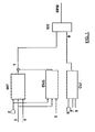
- the continuous control method comprises a block INT which evaluates the contribution of the retarder, when it is present in the engine system, to the fan speed value; moreover a block ENG evaluates the contribution of the engine system, which may comprise several additional elements, such as the turbo-charger circuit, to said value
- the two values are added up in output in order to obtain an overall value 1. In case the retarder is not present, its contribution is null.
- the retarder and the engine cooling system are managed together, since in the overall engine system there is the interaction between the two effects generated by the water heating cycle and by the functioning of the retarder, which brakes the kinematic chain of the vehicle, dissipating the kinetic energy into the heat in the hydraulic cooling circuit.
- the retarder generates heat in a rapid way, thus according to the percentage of braking torque required by the retarder, the block performs a predictive control of which fan speed is necessary in order to cool the water.
- block ENG the engine system
- the block INT estimates the amount of thermal power that the retarder will introduce in the cooling system: as a matter of fact the required fan rotation speed will be higher if the retarder is activated.
- the block INT receives at the input data relating to: a reference temperature parameter 2 of the fluid in the engine cooling system (for example 102 °C) which ideally should be maintained; the percentage 4 of braking torque required by the retarder 4; the current temperature 3 of the fluid in the engine cooling system.
- a reference temperature parameter 2 of the fluid in the engine cooling system for example 102 °C
- the percentage 4 of braking torque required by the retarder 4 the current temperature 3 of the fluid in the engine cooling system.
- the block ENG receives at the input data relating to: the reference temperature parameter 2; the current temperature 3 of the fluid in the engine cooling system; the measured value 5 of the current fan speed.
- a further block CLI suitable to determine and provide as output 9 a fan speed value given by the contribution of the behaviour of the air-conditioning unit.
- a control of the pressure of the gas (freon) in the circuit of the air-conditioning unit which should not exceed a certain value.
- the control of the gas pressure may be performed by controlling the fan rotation speed.
- the block CLI receives at the input data relating to: a constant reference pressure value 6 of the gas (freon) of the cooling circuit, for example 16bar; a current measured pressure value 7 of the freon; a fan speed value 8, for example 850 rpm.
- the fan speed control value RPM is given by the contribution in the output 1. Otherwise, if the block CLI is present, the fan speed control value RPM is determined in a block MX as the highest value between the two values present in the outputs 1 and 9.
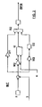
- the blocks INT, ENG, CLI comprise parallel branches which process the input data according to criteria of integration, derivation and multiplication, which are added up and limited in order to obtain the output value.
- the input data are available by means of the internal CAN line.
- the block INT evaluates the difference between the temperature constant 2 and the measured value 3 defined above.
- the difference is provided to three multiplier inputs by the appropriate constants M1, M2, M3, belonging to three parallel branches: the output of M1 is directly provided to an adder S2; the output of M2 feeds an integrator I2 whose second input receives the percentage value 4 of braking torque required by the retarder, and whose output is provided to a second input of the adder S2; the output of M3 is, on the contrary, provided to a third input of the adder S2.
- the latter provides in output the sum of the three received contributions to a saturator, whose output provides the value of the block INT contribution to the fan speed value.
- the block ENG evaluates the difference between the temperature constant 2 and the measured value 3 defined above.
- the difference is provided to three multiplier inputs by the appropriate constants M4, M5, M6, belonging to three parallel branches: the output of M4 is directly provided to an adder S3; the output of M5 feeds an integrator I3 whose second input receives the measured value 5 of the current fan speed, and whose output is provided to a second input of the adder S3; the output of M6 is, on the contrary, provided to a derivator D3, whose output is provided to a third input of the adder S2.
- the latter provides in output the sum of the three received contributions to a saturator, whose output provides the value of the block INT contribution to the fan speed value.
- the block CLI evaluates the difference between the pressure constant 6 of the freon and the measured value 7 defined above.
- the difference is provided to three multiplier inputs by the appropriate constants M7, M8, M9, belonging to three parallel branches: the output of M7 is directly provided to an adder S4; the output of M8 feeds an integrator I4 whose second input receives the fan speed value 8, and whose output is provided to a second input of the adder S4; the output of M6 is, on the contrary, provided to a derivator D4, whose output is provided to a third input of the adder S4.
- the latter provides in output the sum of the three received contributions to a saturator, whose output provides the value of the block CLI contribution to the fan speed value.
- the fan speed control of the continuous type according to the invention may be applied to the electromagnetic coupling by means of a pulse control, using the PWM technique (Pulse Width Modulation).
- the fan speed control of the continuous type optimizes the fuel consumption.
- the pulse control of the type PWM may cause the wearing of the material of the coupling.
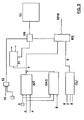
- the system as described above ( fig. 1 ) is completed by decisional blocks, which are able to decide what kind of fan speed control has to be instantly actuated, whether of the continuous or discrete type, according to its evaluations of the driving or travelling conditions.
- the method comprises the block of fig. 1 , and also a block 51 which receives the speed value 1 given by adding up the value calculated by the blocks INT and ENG described above, and evaluates its positioning with respect to two discrete fan speed values, an intermediate value and a maximum value of direct coupling, or the null value, which it chooses at its outputs.
- a decision circuit D5 is foreseen to actuate the decision on the type of fan speed control, enabling the outputs of the block MX described above or of the block 51 according to the signals received at its inputs.
- a block 52 receives a measurement 10 of the current fuel consumption. If said measurement is lower than a threshold 11, for example it is null while braking or when the accelerator pedal is released, the decision circuit D5 provides to the block 51 a choice signal of the original discrete control, since there is no problem of fuel consumption.
- a block 53 may also be present which is able to evaluate the degree of instant and progressive wear of the electromagnetic coupling according to available tabular values.
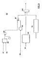
- FIG. 6 A possible embodiment of the block 53 is illustrated in figure 6 .
- Measured values of speed engine (angular speed of the drive shaft), of instant fan speed and of the overall distance covered are available, for example by means of the CAN data line. Moreover, the temperature data of the electromagnetic coupling may also be available.
- the fan speed 61 and the drive shaft speed 62 are provided to a block 65 which verifies the difference between the two speed values, and uses such difference in order to find in a pre-stored table, of the type known, the incremental value of the instant wear (in mm/s) which is currently occurring.
- This wear value is integrated in an integrator 66. Each time the engine is started, the integrator starts from a predetermined value, for example zero; each time the engine is stopped, the obtained value is stored and is then added to the trend obtained in the following functioning of the engine.
- the output of the integrator is provided to a comparator 67 which compares it with a tabular value provided by the block 68, which gives in output a value of expected wear, or tolerable wear, as a function of the overall covered kilometres which are available at the input 63.
- the table is preloaded. If the calculated wear is higher than the expected and tolerable value, then the output of the comparator 67 will provide to the system, as output of the block 53, the indication to choose the speed control of the original discrete type, which minimizes the wear of the coupling.
- the data on the coupling temperature is available, it is provided to the input 64 of a block 69 which evaluates if the coupling temperature is higher than a threshold: then also the output of the block 69 gives to the system the indication to choose the speed control of the discrete type, which minimizes the wear of the coupling.
- An optional block 70 may also be available, suitable for identifying the type of vehicular usage, which, as a matter of fact, evaluates if it is used on motorways or not, according to the available vehicular parameters.
- This block may be realized in a way known in the art.
- a motorway usage would be suitable for a continuous pulse control of the fan speed, in order to minimize fuel consumption.
- a usage for which the dispersion of the thermal flow of the vehicle systems is more difficult such as for example a hilly or mountainous road, with numerous upward slopes, where the fuel consumption increases a lot, the advantage of a continuous control would be less evident, while the risk to wear the coupling may prevail.
- the output of the block 70 gives to the system the indication to choose the speed control of the original discrete type, which minimizes the wear of the coupling.
- the outputs of the blocks 67, 69 and 70 are provided to a logic OR which provides the indication signal about the control type to be actuated by the decision circuit D5 ( fig. 5 ).
- the apparatus suitable for the realization of the method may comprise an electronic control unit, which comprises a software which performs the operations described above, appropriately programmed using the programming techniques available to the person skilled in the art. Moreover the apparatus comprises an interface which converts the fan speed data provided in output by the control unit into an electric signal or similar, whose characteristics depend on the type of coupling device between the fan and the drive shaft. In the example of the electromagnetic coupling described above, the signal is a pulse electric signal.
- control method may advantageously be realized by means of a computer program, which comprises program code means performing one or more steps of said method, when said program is run on a computer.
- program code means performing one or more steps of said method
- the scope of the present patent is meant to cover also said computer program and the computer-readable means that comprises a recorded message, such computer-readable means comprising the program code means for performing one or more steps of such method, when such program is run on a computer.
Landscapes
- Engineering & Computer Science (AREA)
- Chemical & Material Sciences (AREA)
- Combustion & Propulsion (AREA)
- Mechanical Engineering (AREA)
- General Engineering & Computer Science (AREA)
- Control Of Vehicle Engines Or Engines For Specific Uses (AREA)
- Control Of Positive-Displacement Air Blowers (AREA)
Abstract
Description
- The present invention refers to a method and apparatus for controlling the rotation speed of a fan of the engine cooling circuit in a vehicle.
- The propulsion systems using thermal engines are usually equipped with a fluid cooling circuit, with different levels of complexity, which uses a fan.
- There are various vehicle systems that may require the activation of the fan: for example, in addition to the circulation system of the engine cooling fluid, which may include various additional elements such as the turbosupercharger circuit and its respective interrefrigeration steps, also the deceleration systems of the dissipative type, such as for example hydraulic decelerators, known as "retarder", the air-conditioning unit, the power takeoffs, and others.
- Usually there is one single fan placed between the engine and the radiator cores, such as the condenser of the air-conditioning circuit, the interrefrigeration heat-exchanger ("aftercooler") of the turbosupercharger circuit, and the engine cooling radiator.
- It is known in the art to make the fan rotate at different discrete speeds, according to the different conditions detected by specially provided control circuits.
- There are several travel conditions wherein the fan rotation speed would be too high, if the fan was able to rotate only at the maximum speed. This would cause an excessive cooling of the circulating fluids: for example an excessive cooling of the engine oil would increase its viscosity, which increases its friction and the fuel consumption.
- Therefore the cooling fan absorbs a remarkable percentage of the power delivered by the engine, thus stopping it, or decreasing its rotation speed in particular operating conditions, makes it possible to spare a lot of energy.
- The fan is usually activated, for certain vehicular applications, such as for example the commercial and industrial ones, by means of a mechanical connection to the drive shaft, using appropriate devices which, for example, are suitable to control the speed variation, instead of using a direct connection to the drive shaft.
- Devices such as the viscous joint, or the electromagnetic coupling, which generate a friction coupling between fan and engine, are known in the art, and, according to the vehicular conditions, they can vary the gear ratio between drive shaft and fan. The viscous joint has the advantage to provide a continuous gear ratio control, but it has the disadvantage to continually drive the fan which, moreover, has a delayed response to the temperature changes. On the other hand, the electromagnetic coupling provides a reasonable number of levels of engine/fan speed ratio, which results in the advantage of a quicker response and a reduced fan driving when the coupling is disconnected, but it has the disadvantage to provide a less gradual variation of the fan speed. Such different levels determine different power absorption and therefore different fuel consumption levels. Said modalities for varying the fan speed, however, are not optimal, since the simplified decision mode, according to which the fan has two or three discrete progressive speeds, still determines a too high fan rotation speed, which does not optimize the fuel consumption.
- Therefore the aim of the present invention is to overcome all the drawbacks mentioned above related to an activation according to discrete speed levels, and to provide a method and apparatus for controlling the rotation speed of a fan of the engine cooling circuit in a vehicle, which is able to optimize the fan speed variation, and consequently to optimize the fuel consumption, by keeping a satisfactory performance in terms of engine cooling.
- In particular, a continuous control of the fan rotation speed is actuated, which means that a complete decoupling from the rotation of the drive shaft is possible, according to appropriate control strategies, in order to optimize functioning, efficiency and fuel consumption.
- Advantageously, the continuous control of the fan rotation speed is actuated on the coupling joint between fan and engine.
- In case of an electromagnetic joint coupling, a mechanical coupling is actuated by means of a pulse control.
- The subject of the present invention is a method for controlling the rotation speed of a fan of the engine cooling circuit in a vehicle, comprising the steps of: evaluating the contribution to the fan rotation speed deriving from the presence of a retarder in the engine unit, according to the difference between a reference temperature value of the fluid of the engine cooling system and a measured current temperature of the fluid of the engine cooling system, and according to the percentage of braking torque required by the retarder; evaluating the contribution to the fan rotation speed deriving from the engine system, according to the difference between a reference temperature value of the fluid of the engine cooling system and a measured current temperature of the fluid of the engine cooling system, and according to the measured value of the current fan speed; obtaining said fan rotation speed by adding up the contributions from said retarder and engine system.
- The subject of the present invention is also a method for controlling the rotation speed of a fan of the engine cooling circuit in a vehicle, when said fan is coupled to said engine by means of an electromagnetic joint coupling, the method comprising the steps of: evaluating the contribution to the fan rotation speed deriving from the presence of a retarder in the engine unit, according to the difference between a reference temperature value of the fluid of the engine cooling system and a measured current temperature of the fluid of the engine cooling system, and according to the percentage of braking torque required by the retarder; evaluating the contribution to the fan rotation speed deriving from the engine system, according to the difference between a reference temperature value of the fluid of the engine cooling system and a measured current temperature of the fluid of the engine cooling system, and according to the measured value of the current fan speed; obtaining said fan rotation speed by adding up the contributions from said retarder and engine system; comparison of said first speed value with respect to discrete predetermined fan speed values, and providing a second fan rotation speed value, such as one among a null value, an intermediate value and a maximum value of direct coupling between said coupling and said fan; evaluation of a measurement of the current fuel consumption with respect to a threshold, choosing said fan rotation speed as first speed value if said measurement of the current fuel consumption is higher than the threshold, otherwise as second speed value.
- The subject of the present invention is in particular a method and apparatus for controlling the rotation speed of a fan of the engine cooling circuit in a vehicle, as described more fully in the claims which are an integral part of the present description.
- Further purposes and advantages of the present invention will become clear from the following detailed description of a preferred embodiment (and respective alternative embodiments) and the drawings that are attached hereto, which are merely illustrative and non-limitative, in which:
-
figure 1 shows a block diagram of a first alternative embodiment of the method for controlling the fan rotation speed according to the present invention; -
figures 2 ,3 ,4 show block diagrams of embodiments of the INT, ENG, CLI blocks of the method offig. 1 . -
figure 5 shows a block diagram of a second alternative embodiment of the method for controlling the fan rotation speed according to the present invention; -
figure 6 shows a functional block diagram of an embodiment of theblock 53 offig. 5 . - In the drawings the same reference numbers and letters are used to identify the same elements or components.
- In the following there is the description of the method that is object of the invention, which allows to perform a continuous control of the fan rotation speed, allowing the decoupling from the rotation of the drive shaft.
- The method is described with reference to the functional block diagrams of the attached figures, wherein each block corresponds to the logic functions performed by the apparatus which realizes them.
- Different systems of the vehicle may require the activation of the fan, as they generate heat which is transferred in the respective cooling systems. In the non-limitative example described below, the involved systems are the engine unit, the deceleration system (henceforth called retarder), and the air-conditioning unit.
- Said vehicular systems provide, in a way known in the art, for example on the CAN internal data line, signals or magnitudes which, together with others, are used as input of the continuous control system that is object of the invention, which is suitable to provide in output a magnitude expressing the fan rotation speed.
- With reference to
figure 1 , the continuous control method comprises a block INT which evaluates the contribution of the retarder, when it is present in the engine system, to the fan speed value; moreover a block ENG evaluates the contribution of the engine system, which may comprise several additional elements, such as the turbo-charger circuit, to said value The two values are added up in output in order to obtain an overall value 1. In case the retarder is not present, its contribution is null. - The retarder and the engine cooling system are managed together, since in the overall engine system there is the interaction between the two effects generated by the water heating cycle and by the functioning of the retarder, which brakes the kinematic chain of the vehicle, dissipating the kinetic energy into the heat in the hydraulic cooling circuit.
- The retarder generates heat in a rapid way, thus according to the percentage of braking torque required by the retarder, the block performs a predictive control of which fan speed is necessary in order to cool the water. Considering only the contribution of the engine system (block ENG) would excessively delay the optimal intervention of the fan. Therefore the block INT estimates the amount of thermal power that the retarder will introduce in the cooling system: as a matter of fact the required fan rotation speed will be higher if the retarder is activated.
- The block INT receives at the input data relating to: a
reference temperature parameter 2 of the fluid in the engine cooling system (for example 102 °C) which ideally should be maintained; thepercentage 4 of braking torque required by theretarder 4; thecurrent temperature 3 of the fluid in the engine cooling system. - The block ENG receives at the input data relating to: the
reference temperature parameter 2; thecurrent temperature 3 of the fluid in the engine cooling system; the measuredvalue 5 of the current fan speed. - An embodiment of the blocks INT and ENG will be described below with reference respectively to
figures 2 and3 . - Preferably it is also present a further block CLI suitable to determine and provide as output 9 a fan speed value given by the contribution of the behaviour of the air-conditioning unit. As a matter of fact, it is necessary to provide a control of the pressure of the gas (freon) in the circuit of the air-conditioning unit, which should not exceed a certain value. Given that the increase of the gas pressure is correlated to the temperature increase of the respective cooling circuit, the control of the gas pressure may be performed by controlling the fan rotation speed.
- The block CLI receives at the input data relating to: a constant
reference pressure value 6 of the gas (freon) of the cooling circuit, for example 16bar; a current measuredpressure value 7 of the freon; afan speed value 8, for example 850 rpm. - An embodiment of the block CLI will be described below with reference to
figure 4 . - If the block CLI is not present, the fan speed control value RPM is given by the contribution in the output 1. Otherwise, if the block CLI is present, the fan speed control value RPM is determined in a block MX as the highest value between the two values present in the
outputs 1 and 9. - In a non limitative example the blocks INT, ENG, CLI comprise parallel branches which process the input data according to criteria of integration, derivation and multiplication, which are added up and limited in order to obtain the output value. The input data are available by means of the internal CAN line.
- In
fig. 2 the block INT evaluates the difference between thetemperature constant 2 and the measuredvalue 3 defined above. The difference is provided to three multiplier inputs by the appropriate constants M1, M2, M3, belonging to three parallel branches: the output of M1 is directly provided to an adder S2; the output of M2 feeds an integrator I2 whose second input receives thepercentage value 4 of braking torque required by the retarder, and whose output is provided to a second input of the adder S2; the output of M3 is, on the contrary, provided to a third input of the adder S2. The latter provides in output the sum of the three received contributions to a saturator, whose output provides the value of the block INT contribution to the fan speed value. - In
fig. 3 the block ENG evaluates the difference between thetemperature constant 2 and the measuredvalue 3 defined above. The difference is provided to three multiplier inputs by the appropriate constants M4, M5, M6, belonging to three parallel branches: the output of M4 is directly provided to an adder S3; the output of M5 feeds an integrator I3 whose second input receives the measuredvalue 5 of the current fan speed, and whose output is provided to a second input of the adder S3; the output of M6 is, on the contrary, provided to a derivator D3, whose output is provided to a third input of the adder S2. The latter provides in output the sum of the three received contributions to a saturator, whose output provides the value of the block INT contribution to the fan speed value. - In
fig. 4 the block CLI evaluates the difference between thepressure constant 6 of the freon and the measuredvalue 7 defined above. The difference is provided to three multiplier inputs by the appropriate constants M7, M8, M9, belonging to three parallel branches: the output of M7 is directly provided to an adder S4; the output of M8 feeds an integrator I4 whose second input receives thefan speed value 8, and whose output is provided to a second input of the adder S4; the output of M6 is, on the contrary, provided to a derivator D4, whose output is provided to a third input of the adder S4. The latter provides in output the sum of the three received contributions to a saturator, whose output provides the value of the block CLI contribution to the fan speed value. - In the following a description is given of an alternative embodiment of the control method of the fan rotation speed, in case of electromagnetic joint coupling to the drive shaft. It is known in the art to impose the coupling a condition which makes the fan rotate according to discrete speeds, for example two speeds, an intermediate speed and a maximum speed (in addition to the condition of fan stopped), with direct coupling. As said above, this type of speed control may be improved in terms of fuel consumption. On the other hand, the direct coupling guarantees the less possible wear of the material of the coupling.
- The fan speed control of the continuous type according to the invention may be applied to the electromagnetic coupling by means of a pulse control, using the PWM technique (Pulse Width Modulation). The fan speed control of the continuous type, as said, optimizes the fuel consumption. But on the other hand, the pulse control of the type PWM may cause the wearing of the material of the coupling. In order to solve this potential drawback, the system as described above (
fig. 1 ) is completed by decisional blocks, which are able to decide what kind of fan speed control has to be instantly actuated, whether of the continuous or discrete type, according to its evaluations of the driving or travelling conditions. - In this case the method comprises the block of
fig. 1 , and also ablock 51 which receives the speed value 1 given by adding up the value calculated by the blocks INT and ENG described above, and evaluates its positioning with respect to two discrete fan speed values, an intermediate value and a maximum value of direct coupling, or the null value, which it chooses at its outputs. - A decision circuit D5 is foreseen to actuate the decision on the type of fan speed control, enabling the outputs of the block MX described above or of the
block 51 according to the signals received at its inputs. - A
block 52 receives ameasurement 10 of the current fuel consumption. If said measurement is lower than a threshold 11, for example it is null while braking or when the accelerator pedal is released, the decision circuit D5 provides to the block 51 a choice signal of the original discrete control, since there is no problem of fuel consumption. - A
block 53 may also be present which is able to evaluate the degree of instant and progressive wear of the electromagnetic coupling according to available tabular values. - A possible embodiment of the
block 53 is illustrated infigure 6 . - Measured values of speed engine (angular speed of the drive shaft), of instant fan speed and of the overall distance covered are available, for example by means of the CAN data line. Moreover, the temperature data of the electromagnetic coupling may also be available.
- The
fan speed 61 and thedrive shaft speed 62 are provided to ablock 65 which verifies the difference between the two speed values, and uses such difference in order to find in a pre-stored table, of the type known, the incremental value of the instant wear (in mm/s) which is currently occurring. This wear value is integrated in anintegrator 66. Each time the engine is started, the integrator starts from a predetermined value, for example zero; each time the engine is stopped, the obtained value is stored and is then added to the trend obtained in the following functioning of the engine. - The output of the integrator is provided to a
comparator 67 which compares it with a tabular value provided by theblock 68, which gives in output a value of expected wear, or tolerable wear, as a function of the overall covered kilometres which are available at theinput 63. The table is preloaded. If the calculated wear is higher than the expected and tolerable value, then the output of thecomparator 67 will provide to the system, as output of theblock 53, the indication to choose the speed control of the original discrete type, which minimizes the wear of the coupling. Moreover if the data on the coupling temperature is available, it is provided to theinput 64 of ablock 69 which evaluates if the coupling temperature is higher than a threshold: then also the output of theblock 69 gives to the system the indication to choose the speed control of the discrete type, which minimizes the wear of the coupling. - An
optional block 70 may also be available, suitable for identifying the type of vehicular usage, which, as a matter of fact, evaluates if it is used on motorways or not, according to the available vehicular parameters. This block may be realized in a way known in the art. - A motorway usage would be suitable for a continuous pulse control of the fan speed, in order to minimize fuel consumption. On the contrary, a usage for which the dispersion of the thermal flow of the vehicle systems is more difficult, such as for example a hilly or mountainous road, with numerous upward slopes, where the fuel consumption increases a lot, the advantage of a continuous control would be less evident, while the risk to wear the coupling may prevail. Then also the output of the
block 70 gives to the system the indication to choose the speed control of the original discrete type, which minimizes the wear of the coupling. - The outputs of the
blocks fig. 5 ). - The apparatus suitable for the realization of the method may comprise an electronic control unit, which comprises a software which performs the operations described above, appropriately programmed using the programming techniques available to the person skilled in the art. Moreover the apparatus comprises an interface which converts the fan speed data provided in output by the control unit into an electric signal or similar, whose characteristics depend on the type of coupling device between the fan and the drive shaft. In the example of the electromagnetic coupling described above, the signal is a pulse electric signal.
- At least a portion of the control method according to the present invention may advantageously be realized by means of a computer program, which comprises program code means performing one or more steps of said method, when said program is run on a computer. For this reason the scope of the present patent is meant to cover also said computer program and the computer-readable means that comprises a recorded message, such computer-readable means comprising the program code means for performing one or more steps of such method, when such program is run on a computer.
- It will be apparent to the person skilled in the art that further alternative and equivalent embodiments of the invention can be conceived and reduced to practice without departing from the scope of the invention.
- The advantages deriving from the use of this invention are evident.
- Using this solution it is possible to keep an optimal and precise temperature control of the fluid of the different cooling circuits, and therefore it is possible to keep the temperature higher, thus increasing the efficiency of the engine, and reducing the fuel consumption.
- While with the existing systems, given their imprecision and delay of activation, the temperature should be kept lower, in order to avoid problems of overheating.
- From the description set forth above it will be possible for the person skilled in the art to embody the invention with no need of describing further details.
Claims (14)
- Method for controlling the rotation speed of a fan of the engine cooling circuit in a vehicle, comprising the steps of:- evaluating the contribution to the fan rotating speed deriving from the presence of a retarder in the engine unit, according to the difference between a reference temperature value (2) of the fluid of the engine cooling system and a measured current temperature (3) of the fluid of the engine cooling system, and according to a percentage value (4) of the braking torque required by the retarder;- evaluating the contribution to the fan rotating speed deriving from the engine system, according to the difference between a reference temperature value (2) of the fluid of the engine cooling system and a measured current temperature (3) of the fluid of the engine cooling system, and according to a measured value (5) of the current fan speed;- obtaining said fan rotating speed by adding up the contributions given by said retarder and engine system.
- Control method as in the claim 1, further comprising the steps of:- evaluating the contribution to the fan rotating speed deriving from an air-conditioning unit, according to the difference between a reference pressure value of the gas of the air-conditioning cooling system (6), and a current measured value (7) of the gas pressure, and according to a current speed of the fan;- obtaining said fan rotating speed from the highest value between said sum of the contributions given by said retarder and engine system, and said contribution deriving from the air-conditioning unit.
- Control method as in claim 1 or 2, wherein each one of said contributions to the fan rotating speed deriving from said retarder, engine system and air-conditioning unit is determined according to parallel branches which process the input data according to criteria of integration, derivation, and multiplication which are added up and limited in order to obtain an output value.
- Method for controlling the rotation speed of a fan of the engine cooling circuit in a vehicle, said fan being coupled to said engine unit by means of an electromagnetic joint coupling, the method comprising the steps of:- evaluating the contribution to the fan rotating speed deriving from the presence of a retarder in the engine unit, according to the difference between a reference temperature value (2) of the fluid of the engine cooling system and a measured current temperature (3) of the fluid in the engine cooling system, and according to a percentage value (4) of the braking torque required by the retarder;- evaluating the contribution to the fan rotating speed deriving from the engine system, according to the difference between a reference temperature value (2) of the fluid of the engine cooling system and a measured current temperature (3) of the fluid in the engine cooling system, and according to a measured value (5) of the current speed of the fan;- obtaining a first value of the fan rotating speed by adding up the contributions given by said retarder and engine system;- comparing said first speed value with respect to preassigned discrete values of the fan speed, and providing a second value of the fan rotating speed as one among a null value, an intermediate value and a maximum value of direct coupling between said coupling and said fan;- evaluating a measurement (10) of the current fuel consumption with respect to a threshold (11);- choosing said fan rotating speed as said first speed value if said measurement (10) of the current fuel consumption is higher than the threshold, otherwise as said second speed value.
- Control method as in the claim 4, further comprising steps of:- evaluating the contribution to the fan rotating speed deriving from an air-conditioning unit, according to the difference between a reference pressure value of the gas of the air-conditioning cooling system (6), and a measured current value (7) of the gas pressure, and according to a current speed of the fan;- obtaining said first value of the fan rotating speed from the highest between said sum of the contributions given by said retarder and engine system, and said contribution deriving from the air-conditioning unit.
- Control method as in claim 4 or 5, further comprising an evaluation step of the wear degree of said electromagnetic coupling comprising the steps of:- evaluating the difference between a measured engine speed value and a measured fan speed value;- using the difference in order to find in a stored table, an increment value of the instant wear of said electromagnetic coupling;- integrating said increment value of the instant wear adding it up to previous values starting from a first usage of said electromagnetic coupling;- comparing said integrated value with a tabular value (68), which provides in output a value of expected wear, or tolerable wear, as a function of the overall kilometres covered by the vehicle;- choosing of said fan rotating speed as said first speed value if said integrated value is lower than said expected wear value, otherwise as said second speed value.
- Control method as in claim 6, further comprising a comparison step of a measured temperature value of said electromagnetic coupling with respect to a threshold temperature value:- choosing said fan rotating speed as said first speed value if said measured temperature value is lower than threshold temperature value, otherwise as said second speed value.
- Control method as in claim 4 or 5, wherein each one of said contributions to the fan rotating speed deriving from said retarder, engine system and air-conditioning unit is determined according to parallel branches which process the input data according to criteria of integration, derivation, and multiplication which are added up and limited in order to obtain an output value.
- Control method as in claim 3 or 8, wherein the contribution to the fan rotating speed deriving from said retarder (INT) is evaluated by means of the difference between said reference temperature value (2) and the measured value (3); the difference is provided to said three parallel branches which comprise three multiplications by constant values (M1, M2, M3); a first multiplication (M1) is directly provided to an adder (S2); a second multiplication (M2) feeds an integrator (I2) whose second input receives said percentage value (4) of braking torque required by the retarder and whose output is provided to a second input of the adder (S2); a third multiplication (M3) is provided to a derivator (D2) whose output is provided to a third input of the adder (S2); said adder (S2) providing the sum to a saturator, whose output provides said contribution to the fan rotating speed deriving from the presence of the retarder (INT).
- Control method as in claim 3 or 8, wherein the contribution to the fan rotating speed deriving from said engine unit (ENG) is evaluated by means of the difference between said reference temperature value (2) and the measured value (3); the difference is provided to said three parallel branches which comprise three multiplications by constant values (M4, M5, M6); a first multiplication (M4) is directly provided to an adder (S3); a second multiplication (M5) feeds an integrator (I3) whose second input receives said measured value (5) of fan current speed and whose output is provided to a second input of the adder (S3); a third multiplication (M6) is provided to a derivator (D3) whose output is provided to a third input of the adder (S3); said adder (S3) providing the sum to a saturator, whose output provides said contribution to the fan rotating speed deriving from said engine unit (ENG).
- Control method as in claim 3 or 8, wherein the contribution to the fan rotating speed deriving from said air-conditioning unit (CLI) is evaluated by means of the difference between the reference pressure value (6) of the gas of the cooling circuit and a current measured pressure value (7) of the gas; the difference is provided to said three parallel branches which comprise three multiplications by constant values (M7, M8, M9); a first multiplication (M7) is directly provided to an adder (S4) ; a second multiplication (M6) feeds an integrator (I4) whose second input receives said current fan speed value and whose output is provided to a second input of the adder (S4) ; a third multiplication (M9) is provided to a derivator (D4) whose output is provided to a third input of the adder (S4) ; said adder (S4) providing the sum to a saturator, whose output provides said contribution to the fan rotating speed deriving from said air-conditioning unit (CLI).
- Apparatus for controlling the rotation speed of an engine cooling circuit fan, comprising an electronic control unit comprising means for performing the steps of the method according to any of the previous claims, and an interface for converting the output data of said electronic control unit into a control signal for a coupling device between said cooling circuit fan and said vehicle engine.
- Computer program comprising program code means suitable for performing the steps of any claim from 1 to 11, when such program is run on a computer.
- Computer-readable means comprising a recorded program, said computer-readable means comprising program code means suitable for performing the steps according to the claims from 1 to 11, when said program is run on a computer.
Priority Applications (5)
| Application Number | Priority Date | Filing Date | Title |
|---|---|---|---|
| ES09425469T ES2741537T3 (en) | 2009-11-17 | 2009-11-17 | Method and apparatus for controlling the rotation speed of a motor cooling circuit fan in a vehicle |
| EP09425469.5A EP2322777B1 (en) | 2009-11-17 | 2009-11-17 | Method and apparatus for controlling the rotation speed of a fan of the engine cooling circuit in a vehicle |
| AU2010236069A AU2010236069B2 (en) | 2009-11-17 | 2010-10-28 | Method and apparatus for controlling the rotation speed of a fan of the engine cooling circuit in a vehicle |
| BRPI1013443-3A BRPI1013443B1 (en) | 2009-11-17 | 2010-11-17 | method and apparatus for controlling the speed of rotation of a fan of the engine cooling circuit in a vehicle |
| CN201010547599.2A CN102061976B (en) | 2009-11-17 | 2010-11-17 | Method and apparatus for controlling the rotation speed of a fan of the engine cooling circuit in a vehicle |
Applications Claiming Priority (1)
| Application Number | Priority Date | Filing Date | Title |
|---|---|---|---|
| EP09425469.5A EP2322777B1 (en) | 2009-11-17 | 2009-11-17 | Method and apparatus for controlling the rotation speed of a fan of the engine cooling circuit in a vehicle |
Publications (2)
| Publication Number | Publication Date |
|---|---|
| EP2322777A1 true EP2322777A1 (en) | 2011-05-18 |
| EP2322777B1 EP2322777B1 (en) | 2019-05-15 |
Family
ID=42145060
Family Applications (1)
| Application Number | Title | Priority Date | Filing Date |
|---|---|---|---|
| EP09425469.5A Active EP2322777B1 (en) | 2009-11-17 | 2009-11-17 | Method and apparatus for controlling the rotation speed of a fan of the engine cooling circuit in a vehicle |
Country Status (5)
| Country | Link |
|---|---|
| EP (1) | EP2322777B1 (en) |
| CN (1) | CN102061976B (en) |
| AU (1) | AU2010236069B2 (en) |
| BR (1) | BRPI1013443B1 (en) |
| ES (1) | ES2741537T3 (en) |
Cited By (3)
| Publication number | Priority date | Publication date | Assignee | Title |
|---|---|---|---|---|
| CN104895818A (en) * | 2015-04-27 | 2015-09-09 | 潍柴动力股份有限公司 | Control method, device and system of engine electric-control fan |
| WO2024003600A1 (en) * | 2022-06-30 | 2024-01-04 | Volvo Truck Corporation | Method and system and computer program product of controlling vehicle fan speed to regulate coolant temperature |
| CN117519330A (en) * | 2022-07-28 | 2024-02-06 | 比亚迪股份有限公司 | Control method of motor cooling system, motor cooling system and motor |
Families Citing this family (4)
| Publication number | Priority date | Publication date | Assignee | Title |
|---|---|---|---|---|
| CN103883545B (en) * | 2012-12-20 | 2016-03-16 | 北汽福田汽车股份有限公司 | The controlling method of cooling fan of engine and device |
| CN112406462B (en) * | 2020-11-06 | 2022-07-12 | 广州汽车集团股份有限公司 | A cooling fan control method and system based on engine operating efficiency |
| CN114294088B (en) * | 2021-12-30 | 2022-10-28 | 潍柴动力股份有限公司 | Cooling system control method and device, cooling system and driving equipment |
| CN118094760B (en) * | 2024-02-06 | 2025-01-10 | 北京北摩高科摩擦材料股份有限公司 | Method, device, equipment and medium for generating airplane wheel cooling fan model |
Citations (3)
| Publication number | Priority date | Publication date | Assignee | Title |
|---|---|---|---|---|
| DE19710384A1 (en) * | 1997-03-13 | 1998-09-17 | Behr Gmbh & Co | Device for controlling rotational speed for e.g. ventilator for cooling components of vehicle |
| US6328000B1 (en) * | 2000-07-07 | 2001-12-11 | Detroit Diesel Corporation | Closed loop fan control using fan speed feedback |
| WO2008069104A1 (en) * | 2006-11-30 | 2008-06-12 | Komatsu Ltd. | Control device for cooling fan for vehicle |
Family Cites Families (2)
| Publication number | Priority date | Publication date | Assignee | Title |
|---|---|---|---|---|
| DE59808784D1 (en) * | 1997-04-23 | 2003-07-31 | Voith Turbo Kg | Method and device for maximum utilization of the braking effect of a retarder |
| JP4464644B2 (en) * | 2003-09-11 | 2010-05-19 | キャタピラージャパン株式会社 | Fan speed control method |
-
2009
- 2009-11-17 EP EP09425469.5A patent/EP2322777B1/en active Active
- 2009-11-17 ES ES09425469T patent/ES2741537T3/en active Active
-
2010
- 2010-10-28 AU AU2010236069A patent/AU2010236069B2/en active Active
- 2010-11-17 CN CN201010547599.2A patent/CN102061976B/en active Active
- 2010-11-17 BR BRPI1013443-3A patent/BRPI1013443B1/en active IP Right Grant
Patent Citations (4)
| Publication number | Priority date | Publication date | Assignee | Title |
|---|---|---|---|---|
| DE19710384A1 (en) * | 1997-03-13 | 1998-09-17 | Behr Gmbh & Co | Device for controlling rotational speed for e.g. ventilator for cooling components of vehicle |
| US6328000B1 (en) * | 2000-07-07 | 2001-12-11 | Detroit Diesel Corporation | Closed loop fan control using fan speed feedback |
| WO2008069104A1 (en) * | 2006-11-30 | 2008-06-12 | Komatsu Ltd. | Control device for cooling fan for vehicle |
| US20100064991A1 (en) * | 2006-11-30 | 2010-03-18 | Komatsu Ltd. | Control device for cooling fan for vehicle |
Cited By (3)
| Publication number | Priority date | Publication date | Assignee | Title |
|---|---|---|---|---|
| CN104895818A (en) * | 2015-04-27 | 2015-09-09 | 潍柴动力股份有限公司 | Control method, device and system of engine electric-control fan |
| WO2024003600A1 (en) * | 2022-06-30 | 2024-01-04 | Volvo Truck Corporation | Method and system and computer program product of controlling vehicle fan speed to regulate coolant temperature |
| CN117519330A (en) * | 2022-07-28 | 2024-02-06 | 比亚迪股份有限公司 | Control method of motor cooling system, motor cooling system and motor |
Also Published As
| Publication number | Publication date |
|---|---|
| CN102061976A (en) | 2011-05-18 |
| CN102061976B (en) | 2015-07-01 |
| AU2010236069B2 (en) | 2014-05-22 |
| BRPI1013443A2 (en) | 2015-06-30 |
| AU2010236069A1 (en) | 2011-06-02 |
| BRPI1013443B1 (en) | 2021-01-12 |
| ES2741537T3 (en) | 2020-02-11 |
| EP2322777B1 (en) | 2019-05-15 |
Similar Documents
| Publication | Publication Date | Title |
|---|---|---|
| AU2010236069B2 (en) | Method and apparatus for controlling the rotation speed of a fan of the engine cooling circuit in a vehicle | |
| CN102381313B (en) | The method for controlling electric oil pump operating | |
| US6986727B2 (en) | Retarding control for an electric drive machine | |
| CN101680534B (en) | Control device for vehicle | |
| EP3115244A1 (en) | Control apparatus for electrically driven vehicle | |
| EP0952315B1 (en) | A control system for minimizing electricity consumption in a cooling system of an internal combustion engine | |
| WO2019197858A1 (en) | Cooling method and cooling device of electric motor | |
| AU2010236071B2 (en) | Method and device for the predictive estimate of the wear of the coupling joint between a cooling circuit fan and an engine system in a vehicle | |
| JP5389248B2 (en) | Work vehicle and control method of work vehicle | |
| WO2009119256A1 (en) | Drive controller | |
| CN102007324A (en) | Hydraulic control apparatus | |
| JP4813971B2 (en) | Engine control method | |
| JP4075189B2 (en) | Power output device | |
| CN102149565B (en) | Method for controlling a thermoregulation device for a power supply battery of an electric traction vehicle | |
| CN104302153A (en) | Method and apparatus for controlling a coolant circuit thermally coupled to a power electronics device | |
| KR102394783B1 (en) | Control method for preventing overheating of fanclutch | |
| JP5685277B2 (en) | Initial setting method of mechanical automatic transmission | |
| EP4656470A1 (en) | A braking unit | |
| JP2013181613A (en) | Protection and control device for power unit | |
| JP5752723B2 (en) | Initial setting method of mechanical automatic transmission | |
| JP5860824B2 (en) | Initial setting method of mechanical automatic transmission | |
| KR20260065303A (en) | Oil Flow Control Device for Automatic Transmission Cooling and Its Control Method | |
| JP5851433B2 (en) | Initial setting method of mechanical automatic transmission | |
| CN119489834A (en) | Torque converter protection action for high-demand customers |
Legal Events
| Date | Code | Title | Description |
|---|---|---|---|
| PUAI | Public reference made under article 153(3) epc to a published international application that has entered the european phase |
Free format text: ORIGINAL CODE: 0009012 |
|
| AK | Designated contracting states |
Kind code of ref document: A1 Designated state(s): AT BE BG CH CY CZ DE DK EE ES FI FR GB GR HR HU IE IS IT LI LT LU LV MC MK MT NL NO PL PT RO SE SI SK SM TR |
|
| AX | Request for extension of the european patent |
Extension state: AL BA RS |
|
| 17P | Request for examination filed |
Effective date: 20111116 |
|
| 17Q | First examination report despatched |
Effective date: 20120216 |
|
| STAA | Information on the status of an ep patent application or granted ep patent |
Free format text: STATUS: EXAMINATION IS IN PROGRESS |
|
| GRAP | Despatch of communication of intention to grant a patent |
Free format text: ORIGINAL CODE: EPIDOSNIGR1 |
|
| STAA | Information on the status of an ep patent application or granted ep patent |
Free format text: STATUS: GRANT OF PATENT IS INTENDED |
|
| INTG | Intention to grant announced |
Effective date: 20181206 |
|
| GRAS | Grant fee paid |
Free format text: ORIGINAL CODE: EPIDOSNIGR3 |
|
| GRAA | (expected) grant |
Free format text: ORIGINAL CODE: 0009210 |
|
| STAA | Information on the status of an ep patent application or granted ep patent |
Free format text: STATUS: THE PATENT HAS BEEN GRANTED |
|
| AK | Designated contracting states |
Kind code of ref document: B1 Designated state(s): AT BE BG CH CY CZ DE DK EE ES FI FR GB GR HR HU IE IS IT LI LT LU LV MC MK MT NL NO PL PT RO SE SI SK SM TR |
|
| REG | Reference to a national code |
Ref country code: CH Ref legal event code: EP Ref country code: GB Ref legal event code: FG4D |
|
| REG | Reference to a national code |
Ref country code: DE Ref legal event code: R096 Ref document number: 602009058344 Country of ref document: DE |
|
| REG | Reference to a national code |
Ref country code: IE Ref legal event code: FG4D |
|
| REG | Reference to a national code |
Ref country code: NL Ref legal event code: FP |
|
| REG | Reference to a national code |
Ref country code: CH Ref legal event code: NV Representative=s name: HEPP WENGER RYFFEL AG, CH |
|
| REG | Reference to a national code |
Ref country code: SE Ref legal event code: TRGR |
|
| REG | Reference to a national code |
Ref country code: LT Ref legal event code: MG4D |
|
| PG25 | Lapsed in a contracting state [announced via postgrant information from national office to epo] |
Ref country code: FI Free format text: LAPSE BECAUSE OF FAILURE TO SUBMIT A TRANSLATION OF THE DESCRIPTION OR TO PAY THE FEE WITHIN THE PRESCRIBED TIME-LIMIT Effective date: 20190515 Ref country code: NO Free format text: LAPSE BECAUSE OF FAILURE TO SUBMIT A TRANSLATION OF THE DESCRIPTION OR TO PAY THE FEE WITHIN THE PRESCRIBED TIME-LIMIT Effective date: 20190815 Ref country code: PT Free format text: LAPSE BECAUSE OF FAILURE TO SUBMIT A TRANSLATION OF THE DESCRIPTION OR TO PAY THE FEE WITHIN THE PRESCRIBED TIME-LIMIT Effective date: 20190915 Ref country code: HR Free format text: LAPSE BECAUSE OF FAILURE TO SUBMIT A TRANSLATION OF THE DESCRIPTION OR TO PAY THE FEE WITHIN THE PRESCRIBED TIME-LIMIT Effective date: 20190515 Ref country code: LT Free format text: LAPSE BECAUSE OF FAILURE TO SUBMIT A TRANSLATION OF THE DESCRIPTION OR TO PAY THE FEE WITHIN THE PRESCRIBED TIME-LIMIT Effective date: 20190515 |
|
| PG25 | Lapsed in a contracting state [announced via postgrant information from national office to epo] |
Ref country code: LV Free format text: LAPSE BECAUSE OF FAILURE TO SUBMIT A TRANSLATION OF THE DESCRIPTION OR TO PAY THE FEE WITHIN THE PRESCRIBED TIME-LIMIT Effective date: 20190515 Ref country code: BG Free format text: LAPSE BECAUSE OF FAILURE TO SUBMIT A TRANSLATION OF THE DESCRIPTION OR TO PAY THE FEE WITHIN THE PRESCRIBED TIME-LIMIT Effective date: 20190815 Ref country code: GR Free format text: LAPSE BECAUSE OF FAILURE TO SUBMIT A TRANSLATION OF THE DESCRIPTION OR TO PAY THE FEE WITHIN THE PRESCRIBED TIME-LIMIT Effective date: 20190816 |
|
| REG | Reference to a national code |
Ref country code: AT Ref legal event code: MK05 Ref document number: 1133696 Country of ref document: AT Kind code of ref document: T Effective date: 20190515 |
|
| PG25 | Lapsed in a contracting state [announced via postgrant information from national office to epo] |
Ref country code: SK Free format text: LAPSE BECAUSE OF FAILURE TO SUBMIT A TRANSLATION OF THE DESCRIPTION OR TO PAY THE FEE WITHIN THE PRESCRIBED TIME-LIMIT Effective date: 20190515 Ref country code: AT Free format text: LAPSE BECAUSE OF FAILURE TO SUBMIT A TRANSLATION OF THE DESCRIPTION OR TO PAY THE FEE WITHIN THE PRESCRIBED TIME-LIMIT Effective date: 20190515 Ref country code: DK Free format text: LAPSE BECAUSE OF FAILURE TO SUBMIT A TRANSLATION OF THE DESCRIPTION OR TO PAY THE FEE WITHIN THE PRESCRIBED TIME-LIMIT Effective date: 20190515 Ref country code: EE Free format text: LAPSE BECAUSE OF FAILURE TO SUBMIT A TRANSLATION OF THE DESCRIPTION OR TO PAY THE FEE WITHIN THE PRESCRIBED TIME-LIMIT Effective date: 20190515 Ref country code: RO Free format text: LAPSE BECAUSE OF FAILURE TO SUBMIT A TRANSLATION OF THE DESCRIPTION OR TO PAY THE FEE WITHIN THE PRESCRIBED TIME-LIMIT Effective date: 20190515 Ref country code: CZ Free format text: LAPSE BECAUSE OF FAILURE TO SUBMIT A TRANSLATION OF THE DESCRIPTION OR TO PAY THE FEE WITHIN THE PRESCRIBED TIME-LIMIT Effective date: 20190515 |
|
| REG | Reference to a national code |
Ref country code: ES Ref legal event code: FG2A Ref document number: 2741537 Country of ref document: ES Kind code of ref document: T3 Effective date: 20200211 |
|
| REG | Reference to a national code |
Ref country code: DE Ref legal event code: R097 Ref document number: 602009058344 Country of ref document: DE |
|
| PG25 | Lapsed in a contracting state [announced via postgrant information from national office to epo] |
Ref country code: SM Free format text: LAPSE BECAUSE OF FAILURE TO SUBMIT A TRANSLATION OF THE DESCRIPTION OR TO PAY THE FEE WITHIN THE PRESCRIBED TIME-LIMIT Effective date: 20190515 |
|
| PLBE | No opposition filed within time limit |
Free format text: ORIGINAL CODE: 0009261 |
|
| STAA | Information on the status of an ep patent application or granted ep patent |
Free format text: STATUS: NO OPPOSITION FILED WITHIN TIME LIMIT |
|
| PG25 | Lapsed in a contracting state [announced via postgrant information from national office to epo] |
Ref country code: TR Free format text: LAPSE BECAUSE OF FAILURE TO SUBMIT A TRANSLATION OF THE DESCRIPTION OR TO PAY THE FEE WITHIN THE PRESCRIBED TIME-LIMIT Effective date: 20190515 |
|
| 26N | No opposition filed |
Effective date: 20200218 |
|
| PG25 | Lapsed in a contracting state [announced via postgrant information from national office to epo] |
Ref country code: PL Free format text: LAPSE BECAUSE OF FAILURE TO SUBMIT A TRANSLATION OF THE DESCRIPTION OR TO PAY THE FEE WITHIN THE PRESCRIBED TIME-LIMIT Effective date: 20190515 |
|
| PG25 | Lapsed in a contracting state [announced via postgrant information from national office to epo] |
Ref country code: SI Free format text: LAPSE BECAUSE OF FAILURE TO SUBMIT A TRANSLATION OF THE DESCRIPTION OR TO PAY THE FEE WITHIN THE PRESCRIBED TIME-LIMIT Effective date: 20190515 |
|
| PG25 | Lapsed in a contracting state [announced via postgrant information from national office to epo] |
Ref country code: LU Free format text: LAPSE BECAUSE OF NON-PAYMENT OF DUE FEES Effective date: 20191117 Ref country code: MC Free format text: LAPSE BECAUSE OF FAILURE TO SUBMIT A TRANSLATION OF THE DESCRIPTION OR TO PAY THE FEE WITHIN THE PRESCRIBED TIME-LIMIT Effective date: 20190515 |
|
| REG | Reference to a national code |
Ref country code: BE Ref legal event code: MM Effective date: 20191130 |
|
| PG25 | Lapsed in a contracting state [announced via postgrant information from national office to epo] |
Ref country code: IE Free format text: LAPSE BECAUSE OF NON-PAYMENT OF DUE FEES Effective date: 20191117 |
|
| PG25 | Lapsed in a contracting state [announced via postgrant information from national office to epo] |
Ref country code: BE Free format text: LAPSE BECAUSE OF NON-PAYMENT OF DUE FEES Effective date: 20191130 |
|
| PG25 | Lapsed in a contracting state [announced via postgrant information from national office to epo] |
Ref country code: CY Free format text: LAPSE BECAUSE OF FAILURE TO SUBMIT A TRANSLATION OF THE DESCRIPTION OR TO PAY THE FEE WITHIN THE PRESCRIBED TIME-LIMIT Effective date: 20190515 |
|
| PG25 | Lapsed in a contracting state [announced via postgrant information from national office to epo] |
Ref country code: IS Free format text: LAPSE BECAUSE OF FAILURE TO SUBMIT A TRANSLATION OF THE DESCRIPTION OR TO PAY THE FEE WITHIN THE PRESCRIBED TIME-LIMIT Effective date: 20190915 |
|
| PG25 | Lapsed in a contracting state [announced via postgrant information from national office to epo] |
Ref country code: MT Free format text: LAPSE BECAUSE OF FAILURE TO SUBMIT A TRANSLATION OF THE DESCRIPTION OR TO PAY THE FEE WITHIN THE PRESCRIBED TIME-LIMIT Effective date: 20190515 Ref country code: HU Free format text: LAPSE BECAUSE OF FAILURE TO SUBMIT A TRANSLATION OF THE DESCRIPTION OR TO PAY THE FEE WITHIN THE PRESCRIBED TIME-LIMIT; INVALID AB INITIO Effective date: 20091117 |
|
| PG25 | Lapsed in a contracting state [announced via postgrant information from national office to epo] |
Ref country code: MK Free format text: LAPSE BECAUSE OF FAILURE TO SUBMIT A TRANSLATION OF THE DESCRIPTION OR TO PAY THE FEE WITHIN THE PRESCRIBED TIME-LIMIT Effective date: 20190515 |
|
| P01 | Opt-out of the competence of the unified patent court (upc) registered |
Effective date: 20230523 |
|
| REG | Reference to a national code |
Ref country code: CH Ref legal event code: U11 Free format text: ST27 STATUS EVENT CODE: U-0-0-U10-U11 (AS PROVIDED BY THE NATIONAL OFFICE) Effective date: 20251201 |
|
| PGFP | Annual fee paid to national office [announced via postgrant information from national office to epo] |
Ref country code: NL Payment date: 20251124 Year of fee payment: 17 |
|
| PGFP | Annual fee paid to national office [announced via postgrant information from national office to epo] |
Ref country code: DE Payment date: 20251126 Year of fee payment: 17 |
|
| PGFP | Annual fee paid to national office [announced via postgrant information from national office to epo] |
Ref country code: GB Payment date: 20251125 Year of fee payment: 17 |
|
| PGFP | Annual fee paid to national office [announced via postgrant information from national office to epo] |
Ref country code: IT Payment date: 20251110 Year of fee payment: 17 |
|
| PGFP | Annual fee paid to national office [announced via postgrant information from national office to epo] |
Ref country code: FR Payment date: 20251124 Year of fee payment: 17 |
|
| PGFP | Annual fee paid to national office [announced via postgrant information from national office to epo] |
Ref country code: SE Payment date: 20251124 Year of fee payment: 17 Ref country code: CH Payment date: 20251201 Year of fee payment: 17 |
|
| PGFP | Annual fee paid to national office [announced via postgrant information from national office to epo] |
Ref country code: ES Payment date: 20251209 Year of fee payment: 17 |