EP2322312A1 - Method for manufacturing laser-welded steel pipe - Google Patents
Method for manufacturing laser-welded steel pipe Download PDFInfo
- Publication number
- EP2322312A1 EP2322312A1 EP09770280A EP09770280A EP2322312A1 EP 2322312 A1 EP2322312 A1 EP 2322312A1 EP 09770280 A EP09770280 A EP 09770280A EP 09770280 A EP09770280 A EP 09770280A EP 2322312 A1 EP2322312 A1 EP 2322312A1
- Authority
- EP
- European Patent Office
- Prior art keywords
- laser
- keyhole
- welded steel
- laser beam
- open pipe
- Prior art date
- Legal status (The legal status is an assumption and is not a legal conclusion. Google has not performed a legal analysis and makes no representation as to the accuracy of the status listed.)
- Granted
Links
Images



Classifications
-
- B—PERFORMING OPERATIONS; TRANSPORTING
- B21—MECHANICAL METAL-WORKING WITHOUT ESSENTIALLY REMOVING MATERIAL; PUNCHING METAL
- B21C—MANUFACTURE OF METAL SHEETS, WIRE, RODS, TUBES, PROFILES OR LIKE SEMI-MANUFACTURED PRODUCTS OTHERWISE THAN BY ROLLING; AUXILIARY OPERATIONS USED IN CONNECTION WITH METAL-WORKING WITHOUT ESSENTIALLY REMOVING MATERIAL
- B21C37/00—Manufacture of metal sheets, rods, wire, tubes, profiles or like semi-manufactured products, not otherwise provided for; Manufacture of tubes of special shape
- B21C37/06—Manufacture of metal sheets, rods, wire, tubes, profiles or like semi-manufactured products, not otherwise provided for; Manufacture of tubes of special shape of tubes or metal hoses; Combined procedures for making tubes, e.g. for making multi-wall tubes
- B21C37/08—Making tubes with welded or soldered seams
-
- B—PERFORMING OPERATIONS; TRANSPORTING
- B23—MACHINE TOOLS; METAL-WORKING NOT OTHERWISE PROVIDED FOR
- B23K—SOLDERING OR UNSOLDERING; WELDING; CLADDING OR PLATING BY SOLDERING OR WELDING; CUTTING BY APPLYING HEAT LOCALLY, e.g. FLAME CUTTING; WORKING BY LASER BEAM
- B23K26/00—Working by laser beam, e.g. welding, cutting or boring
- B23K26/02—Positioning or observing the workpiece, e.g. with respect to the point of impact; Aligning, aiming or focusing the laser beam
- B23K26/03—Observing, e.g. monitoring, the workpiece
-
- B—PERFORMING OPERATIONS; TRANSPORTING
- B23—MACHINE TOOLS; METAL-WORKING NOT OTHERWISE PROVIDED FOR
- B23K—SOLDERING OR UNSOLDERING; WELDING; CLADDING OR PLATING BY SOLDERING OR WELDING; CUTTING BY APPLYING HEAT LOCALLY, e.g. FLAME CUTTING; WORKING BY LASER BEAM
- B23K26/00—Working by laser beam, e.g. welding, cutting or boring
- B23K26/02—Positioning or observing the workpiece, e.g. with respect to the point of impact; Aligning, aiming or focusing the laser beam
- B23K26/03—Observing, e.g. monitoring, the workpiece
- B23K26/032—Observing, e.g. monitoring, the workpiece using optical means
-
- B—PERFORMING OPERATIONS; TRANSPORTING
- B23—MACHINE TOOLS; METAL-WORKING NOT OTHERWISE PROVIDED FOR
- B23K—SOLDERING OR UNSOLDERING; WELDING; CLADDING OR PLATING BY SOLDERING OR WELDING; CUTTING BY APPLYING HEAT LOCALLY, e.g. FLAME CUTTING; WORKING BY LASER BEAM
- B23K26/00—Working by laser beam, e.g. welding, cutting or boring
- B23K26/20—Bonding
- B23K26/21—Bonding by welding
- B23K26/24—Seam welding
- B23K26/26—Seam welding of rectilinear seams
- B23K26/262—Seam welding of rectilinear seams of longitudinal seams of tubes
-
- B—PERFORMING OPERATIONS; TRANSPORTING
- B23—MACHINE TOOLS; METAL-WORKING NOT OTHERWISE PROVIDED FOR
- B23K—SOLDERING OR UNSOLDERING; WELDING; CLADDING OR PLATING BY SOLDERING OR WELDING; CUTTING BY APPLYING HEAT LOCALLY, e.g. FLAME CUTTING; WORKING BY LASER BEAM
- B23K26/00—Working by laser beam, e.g. welding, cutting or boring
- B23K26/346—Working by laser beam, e.g. welding, cutting or boring in combination with welding or cutting covered by groups B23K5/00 - B23K25/00, e.g. in combination with resistance welding
- B23K26/348—Working by laser beam, e.g. welding, cutting or boring in combination with welding or cutting covered by groups B23K5/00 - B23K25/00, e.g. in combination with resistance welding in combination with arc heating, e.g. tungsten inert gas [TIG], metal inert gas [MIG] or plasma welding
-
- B—PERFORMING OPERATIONS; TRANSPORTING
- B23—MACHINE TOOLS; METAL-WORKING NOT OTHERWISE PROVIDED FOR
- B23K—SOLDERING OR UNSOLDERING; WELDING; CLADDING OR PLATING BY SOLDERING OR WELDING; CUTTING BY APPLYING HEAT LOCALLY, e.g. FLAME CUTTING; WORKING BY LASER BEAM
- B23K2101/00—Articles made by soldering, welding or cutting
- B23K2101/04—Tubular or hollow articles
- B23K2101/06—Tubes
-
- B—PERFORMING OPERATIONS; TRANSPORTING
- B23—MACHINE TOOLS; METAL-WORKING NOT OTHERWISE PROVIDED FOR
- B23K—SOLDERING OR UNSOLDERING; WELDING; CLADDING OR PLATING BY SOLDERING OR WELDING; CUTTING BY APPLYING HEAT LOCALLY, e.g. FLAME CUTTING; WORKING BY LASER BEAM
- B23K2101/00—Articles made by soldering, welding or cutting
- B23K2101/04—Tubular or hollow articles
- B23K2101/10—Pipe-lines
-
- B—PERFORMING OPERATIONS; TRANSPORTING
- B23—MACHINE TOOLS; METAL-WORKING NOT OTHERWISE PROVIDED FOR
- B23K—SOLDERING OR UNSOLDERING; WELDING; CLADDING OR PLATING BY SOLDERING OR WELDING; CUTTING BY APPLYING HEAT LOCALLY, e.g. FLAME CUTTING; WORKING BY LASER BEAM
- B23K2103/00—Materials to be soldered, welded or cut
- B23K2103/02—Iron or ferrous alloys
- B23K2103/04—Steel or steel alloys
Definitions
- the present invention relates to methods for manufacturing a steel pipe obtained by welding the longitudinal edges of an open pipe with a laser beam (hereinafter, referred to as a laser welded steel pipe), in particular, a method for manufacturing a laser welded steel pipe suitable for digging and transportation of oil and natural gas, such as oil country tubular goods or a line pipe.
- Steel pipes known as oil country tubular goods or line pipes fall into two broad categories: welded steel pipes (e.g., electric resistance welded steel pipes and UOE steel pipes) and seamless steel pipes.
- electric resistance welded steel pipes can be manufactured at low cost by using a hot rolled steel strip (so-called a hot rolled steel coil) as the raw material and thus are economically advantageous.
- electric resistance welded steel pipes are usually manufactured by forming steel strips into cylindrical open pipes with forming rolls (here, the open pipes are pipe-like steel strips that are formed using multiple forming rolls and have the edges thereof unwelded; hereinafter, such pipe-like steel strips are referred to as open pipes) and then welding the longitudinal edges of the open pipes (i.e., both edges of each cylindrical steel strip) by electric resistance welding (also referred to as high-frequency resistance welding) while compressing the longitudinal edges using squeeze rolls; thus, electrical resistance welded steel pipes unavoidably have a weld (so-called a seam) and the problem of a deteriorated low-temperature toughness of the seam.
- a weld weld
- a seam weld
- Electric resistance welded steel pipes have another problem: Alloy elements often segregate in molten metal while the longitudinal edges are being welded, and thus the corrosion resistance of the seam is often deteriorated. Thus, oil country tubular goods and line pipes based on electric resistance welded steel pipes have a problem with the use in the harsh corrosion environment (e.g., the sour environment).
- laser welding has attracted attention as a welding method that does not deteriorate the low-temperature toughness or the corrosion resistance of the seam.
- the heat source can be small in dimensions, heat energy can converge to a high density, and thus the formation of oxide and the segregation of alloy elements in molten metal can be prevented. Therefore, if laser welding is applied to the manufacturing of welded steel pipes, then the deterioration of the low-temperature toughness and corrosion resistance of the seam can be prevented.
- the manufacturing process of welded steel pipes has introduced a technology to produce a steel pipe by welding the longitudinal edges of an open pipe under irradiation with a laser beam (i.e., laser welded steel pipes).
- the seam of the laser welded steel pipe may have an opening if the contact point of the longitudinal edges of the open pipe, at which the squeeze rolls compress the longitudinal edges (hereinafter, referred to as the contact point or the squeezing point) has a shift from the circumferential position of irradiation with the laser beam; the portion having such an opening should be handled as a welding defect and removed, and this decreases the yield rate of laser welded steel pipes.
- Japanese Unexamined Patent Application Publication No. H10-76383 discloses a technique to assess the status of laser welding, in which a laser beam is applied to one side of a steel strip, and a plasma illumination emerging on the other side is monitored.
- the plasma illumination scatters over a wide area, and thus, with this technique, it is difficult to have an accurate understanding of the status of laser welding and impossible to detect any shift of the position of irradiation with the laser beam from the longitudinal edges accurately.
- Japanese Unexamined Patent Application Publication No. H8-267241 discloses a technique to assess the formation status of penetration beads, in which the emission intensity generated by laser welding is measured.
- the emission intensity greatly varies because of various factors, and thus, with this technique, it is difficult to have an accurate understanding of the formation status of penetration beads.
- Japanese Unexamined Patent Application Publication No. 2001-25867 discloses a technique to control welding conditions, in which molten metal formed by arc welding is imaged, and the obtained image is used to analyze the shape of penetration beads.
- the direct application of this technique for arc welding to laser welding fails to provide a clear image of molten metal. This is because in laser welding, heat energy converges to a high density, and thus an excessive light intensity is generated. As a result, it is difficult in laser welding to have an accurate understanding of the shape of penetration beads.
- Japanese Unexamined Patent Application Publication No. 2001-25867 discloses a technique of irradiating molten metal with a laser beam through an interference filter; however, this laser beam is used to image molten metal and thus has no contribution to welding.
- the present invention is intended to provide a method for manufacturing a laser welded steel pipe at a high yield rate and in a stable manner, in which the status of laser welding is accurately assessed during manufacturing of the laser welded steel pipe, and the assessment is used to modify welding conditions.
- the present invention is as follows:
- the status of laser welding can be accurately assessed during the manufacturing of laser welded steel pipes, and the assessment can be used to modify welding conditions so that the contact point of the longitudinal edges can be always located in keyhole(s) or molten metal formed by irradiation with laser beam(s).
- laser welded steel pipes can be manufactured at a high yield rate and in a stable manner.
- the obtained laser welded steel pipes are excellent in terms of the low-temperature toughness and the corrosion resistance of the seam thereof and thus can be suitable for the use as oil country tubular goods or line pipes that are used in cold districts or the corrosion environment.
- 1 open pipe; 2: longitudinal edge; 3, 3-1, 3-2, 3-3, and 3-4: laser beam; 4: keyhole; 5: molten metal; 6: seam; 7: mandrel bar; 8: monitoring camera; 9: illuminating device; 10: plasma illumination sensor; 11: image processor; 12: assessment device; 13: position controller; 14: welding head; 15: reflected-light sensor; 16: monitoring device; 17: monitoring device; 18: electrode; 19: arc; 20: welding current; 21: Lorentz force
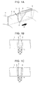
- FIG. 1A is an oblique perspective diagram schematically illustrating an example of welding at the contact point of the longitudinal edges 2 of an open pipe 1 according to the present invention.
- Arrow A in Fig. 1A represents the direction of travel of the open pipe.
- a keyhole 4 and molten metal 5 formed around it, both generated by irradiation with a laser beam 3, are shown in perspective diagrams.
- Fig. 1A a deep cavity 4 (hereinafter, referred to as a keyhole 4) in molten metal 5, as shown in Fig. 1A .
- a keyhole 4 a deep cavity 4
- Figs. 1B and 1C are perspective diagrams derived from Fig. 1A , illustrating the keyhole 4 and molten metal 5 formed around it on a cross-section taken in the circumferential direction of the pipe (in the direction perpendicular to the welding line).
- This keyhole 4 indicates the point at which the heat energy of the laser beam 3 converges to the highest density.
- a laser welded steel pipe can be manufactured in a stable manner by monitoring the keyhole 4 and, as shown in Fig. 1B , performing laser welding in such a manner that the contact point C of the longitudinal edges can be located in the keyhole 4.
- matching the contact point C of the longitudinal edges 2 to the keyhole 4 requires a high-accuracy position control technique.
- laser welding may be so performed that the contact point C of the longitudinal edges 2 can be located in molten metal 5, which is formed around the keyhole 4.
- Molten metal 5 has a length Lm in the circumferential direction of the pipe (in the direction perpendicular to the welding line) greater than the size of the keyhole 4, Lk, and thus the irradiation point of the laser beam can be easily controlled in the circumferential direction of the pipe by relatively easy techniques, which are based on the positional control of a welding head 14, and a converging lens or a converging mirror housed in the welding head 14; in this way, the laser welded steel pipe can be manufactured in a stable manner.
- the contact point C of the longitudinal edges 2 may be any point on the direction of travel A of the open pipe 1 as long as at that point the mean gap width G of the longitudinal edges 2 measured in the thickness direction has been reduced to 0.5 mm or smaller by squeeze rolls.
- the keyhole 4 penetrates from the outer surface to the inner surface of molten metal 5 and can be monitored accurately.
- the present invention was made on the basis of these findings.
- the open pipe 1 shown in Fig. 1A is obtained by forming a steel strip into a cylinder with forming rolls. With the longitudinal edges 2 of this open pipe 1 compressed with squeeze rolls (not shown in the drawing), the open pipe 1 is irradiated with the laser beam 3 from the side of the outer surface thereof. At the same time, the irradiation point of the laser beam 3 is monitored from the side of the inner surface of the open pipe 1 for detection of the keyhole 4.
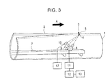
- the keyhole 4 can be easily detected by ordinary image processing techniques as long as it can penetrate from the outer surface to the inner surface of the open pipe 1. The keyhole 4 detected on the side of the inner surface would mean that stable laser welding is in progress; in this case, welding conditions are kept unchanged. Note that Fig. 1A shows no monitoring device for the keyhole 4 therein; the keyhole monitoring device used in the present invention is shown in Fig. 3 .
- the keyhole 4 not found would mean that the keyhole 4 is closed; in this case, welding conditions should be modified and so adjusted that stable laser welding can progress. And, if the keyhole 4 can be detected under the modified welding conditions, then laser welding is performed with these welding conditions maintained. Note that the keyhole 4 is the most likely to be closed when the contact point C of the longitudinal edges 2 deviates out of the keyhole 4 or from molten metal 5, which is formed around the keyhole 4.
- Specific welding conditions reached by adjustment when the keyhole 4 is closed are the most preferably ones under which the irradiation point of the laser beam is moved in the circumferential direction of the open pipe 1 so that the contact point C of the longitudinal edges 2 can be located at the irradiation point of the laser beam 3 (the keyhole 4) or in molten metal 5.
- the contact point of the longitudinal edges 2 as well as the positions of the keyhole 4 and molten metal 5 are subjected to image processing based on a keyhole monitoring device and thus recognized, the circumferential direction and the distance of travel of the open pipe are calculated, and then the irradiation point of the laser beam 3 is moved by controlling the positions of the welding head 14 and a converging lens or a converging mirror housed in the welding head 14 so that the contact point C of the longitudinal edges 2 can be located in the keyhole 4 or molten metal 5.
- Such an adjustment of the positional relationship between the contact point of the longitudinal edges 2 and the keyhole 4 or molten metal 5 can be easily achieved by monitoring the open pipe 1 from the side of the inner surface thereof to detect the keyhole 4.
- the keyhole 4 When the size of the keyhole 4 measured on the side of the inner surface is smaller than 0.2 mm in diameter, the keyhole 4 may possibly be in a closed state.
- the keyhole 4 preferably has a diameter equal to or greater than 0.2 mm on the side of the inner surface.
- the diameter measured on the side of the inner surface exceeds 1.0 mm, not only welding defects such as burn-through occur, but also the width of the weld left after molten metal is solidified (i.e., the seam 6) is significantly expanded, thereby disfiguring the laser welded steel pipe.
- the diameter of the keyhole 4 measured on the side of the inner surface of the open pipe 1 is more preferably in the range of 0.2 to 1.0 mm.
- the minor axis is preferably equal to or longer than 0.2 mm. Note that the size of the keyhole 4 was monitored from the inside of the open pipe 1 using a monitoring camera 8 fastened on a mandrel bar 7 suspended between stands, as shown in Fig. 3 .
- Imaging conditions were as follows: the inner surface of the open pipe 1 was irradiated by an illuminating device 9 with a ray of light having a wavelength component different from those of the laser beam and the plasma illumination used, for example, an ultraviolet ray having a wavelength of 337 nm, and imaged through a filter that allows only rays of light having this wavelength to pass through, so that any disturbance due to infrared light, plasma illuminations, or other kinds of light coming from the keyhole 4 or molten metal 5 could be prevented.
- the wavelength allowed to pass through the filter is chosen depending on the spectrum of the plasma light emission, to have a band of wavelength different from this spectrum, with available light sources and filters also taken into account.
- the camera speed was set at 30 frames per second, and the mean value thereof was calculated using five still images randomly sampled.
- the shape of the keyhole on the side of the inner surface was almost perfectly circular or ellipsoidal; when the shape of the keyhole was ellipsoidal, the minor axis was measured.
- an image processor 11, which processes a video shot by the monitoring camera 8 to form the images of the contact point C of the longitudinal edges 2, the keyhole 4, and molten metal 5 and then digitizes the dimensions and positions of them, as well as an assessment device 12 and a position controller 13 for the laser beam were used to judge whether the keyhole 4 was closed and control the irradiation point of the laser beam.
- the monitoring device for the keyhole 4 is never limited to the constitution described above; it may have any other possible constitution.
- FIGs. 2A to 2E are plan views of an open pipe with the irradiation points of a plurality of laser beams. Arrow A in each drawing represents the direction of travel of the open pipe.
- Fig. 2A shows an arrangement for irradiation with two laser beams, illustrating an example in which laser beams 3-1 and 3-2 are arranged across the longitudinal edges.
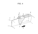
- Fig. 4 is an oblique perspective diagram schematically illustrating an example of welding at the contact point of the longitudinal edges of an open pipe using laser beams arranged as shown in Fig. 2A . Arrow A in Fig.
- Fig. 4 represents the direction of travel of the open pipe. Note that keyholes 4 and molten metal 5 formed around them, both generated by irradiation with the two laser beams 3, are shown in perspective diagrams.
- Fig. 2B shows an arrangement for irradiation with three laser beams and is an example in which a laser beam 3-1 heats the longitudinal edges first and then laser beams 3-2 and 3-3 are arranged across the longitudinal edges.
- Fig. 2C shows an arrangement for irradiation with four laser beams and is an example in which four laser beams 3-1, 3-2, 3-3, and 3-4 are arranged pairwise across the longitudinal edges.
- Fig. 2B shows an arrangement for irradiation with three laser beams and is an example in which a laser beam 3-1 heats the longitudinal edges first and then laser beams 3-2 and 3-3 are arranged across the longitudinal edges.
- Fig. 2C shows an arrangement for irradiation with four laser beams and is an example in which four laser beams 3-1,
- FIG. 2D shows an arrangement for irradiation with two laser beams and is an example in which laser beams 3-1 and 3-2 having different laser power levels are arranged across the longitudinal edges. This is an example of arrangement in which the power of the laser beam 3-1 is smaller than that of the laser beam 3-2, and thus the laser beam 3-1 is closer to the longitudinal edges.
- Fig. 2E shows an arrangement for irradiation with two laser beams and is an example in which two laser beams 3-1 and 3-2 are longitudinally aligned (in tandem) along the longitudinal edges.
- the laser beams are handled not as a plurality of laser beams but as a single laser beam.
- all to be monitored is the keyhole formed by the laser beam 3-2, which is the closest to molten metal.
- Three or more laser beams longitudinally aligned (in tandem) along the longitudinal edges would also be handled as a single laser beam.
- all to be monitored is also the keyhole that is the closest to molten metal.
- the arrangement of the irradiation points of the laser beams is never limited to the examples shown in Figs. 2A to 2E ; they can be freely arranged for specific purposes.
- the number of laser beams used in the present invention is preferably in the range of one to four. Five or more laser beams would be disadvantageous because of equipment cost, manufacturing cost, and a complicated positional control of the laser beams.
- a plurality of keyholes 4 are all monitored, and laser welding is so performed that the contact point of the longitudinal edges 2 can be located between the two keyholes that are located across the longitudinal edges 2 and whose distances to the longitudinal edges 2 in the direction perpendicular to the longitudinal edges (L1 and L2) are longer than that of any other keyhole, as shown in Figs. 2A to 2E .
- positioning the contact point of the longitudinal edges 2 at this definite point requires a high-accuracy control technique.
- laser welding may be so performed that the contact point of the longitudinal edges 2 can be controlled to be located in molten metal 5, which is formed around the two keyholes 4.
- Molten metal 5 has a length Lm in the circumferential direction of the pipe (in the direction perpendicular to the welding line) greater than the size of each keyhole 4, Lk, and thus relatively easy techniques can be used for control.
- Such an adjustment of the positional relationship between the contact point of the longitudinal edges 2 and two keyholes 4 or molten metal 5 formed between these two keyholes 4 can be easily performed by monitoring the open pipe 1 from the side of the inner surface thereof to detect the keyholes 4.
- the number of molten pools is often one.
- keyholes 4 all having a size of less than 0.1 mm on the side of the inner surface would possibly lead to a closed state of any of the keyholes 4.
- the keyholes 4 preferably have diameters equal to or greater than 0.1 mm on the side of the inner surface.
- the diameter measured on the side of the inner surface exceeds 1.0 mm, not only welding defects such as burn-through occur, but also the width of the weld left after molten metal is solidified (i.e., the seam 6) is significantly expanded, thereby disfiguring the laser welded steel pipe.
- the diameters of the keyholes 4 measured on the side of the inner surface of the open pipe 1 are more preferably in the range of 0.1 to 1.0 mm.
- the shape of the keyholes is ellipsoidal, the minor axes are preferably equal to or longer than 0.1 mm.
- the laser beams are handled not as a plurality of laser beams but as a single laser beam, and thus all to be monitored is the keyhole formed by the laser beam 3-2, which is the closest to molten metal 5; so, the keyhole 4 preferably has a diameter equal to or greater than 0.2 mm on the side of the inner surface.
- any closed state of the keyhole 4 would affect the manufacturing of the laser welded steel pipe even if it lasts only for a short period of time.
- a closed state lasting for 0.01 seconds or longer in laser welding progressing at a welding speed exceeding 5 m/min would cause welding defects due to many spatters, such as insufficient melting and undercutting, thereby leading to a decreased yield rate of laser welded steel pipes.
- Such a closed state of any keyhole disappearing in a short period of time is difficult to detect only by monitoring the keyhole in the above-described manner.
- the status of the keyhole is analyzed by, besides the monitoring of the keyhole, measuring a ray of reflected light and a plasma illumination both generated from the irradiation point of the laser beam using sensors, and the status of welding is monitored on the basis of the relative values of the measurement obtained for the ray of reflected light and that for plasma illumination.
- the ray of reflected light generated from the irradiation point of the laser beam is preferably measured from the side of the outer surface of the open pipe 1. The reason for this is because it allows the intensity of reflected light to be measured accurately even when a short-time closed state of the keyhole occurs.
- the plasma illumination generated from the irradiation point of the laser beam is preferably measured from the side of the inner surface of the open pipe 1.
- the reason for this is because on the side of the outer surface of the open pipe 1, plasma illuminations generated by the laser excitation of shielding gas and fumes cause disturbance, leading to a decreased measurement accuracy; however, measuring the plasma illumination from the side of the inner surface would be free from plasma generation on the side of the inner surface when a short-time closed state of the keyhole 4 occurs, thereby ensuring that the presence or absence of any closed state of the keyhole of can be determined accurately.
- the ray of reflected light was monitored from the outside of the open pipe 1 using a reflected-light sensor 15, which was suspended from a welding head 14, and a monitoring device 16, as shown in Fig. 5 .
- Conditions for data collection were as follows: Measurement was performed with the reflected-light sensor 15 equipped with a filter that allowed only rays of light having the same wavelength as laser to pass through, so that any disturbance due to infrared light coming from the keyhole 4 or molten metal 5 could be prevented. Fluctuations in the intensity of the reflected light were assessed using the monitoring device 16. For example, a photodiode or other similar devices can be used as the reflected-light sensor.
- rays of reflected light coaxial with laser light can be measured by delivering it to the reflected-light sensor using a mirror housed in the welding head or by some other means.
- the measurement of the plasma illumination measurement was performed with a plasma illumination sensor 10 installed along with the monitoring device for the keyhole, as shown in Fig. 3 .
- Conditions for data collection were as follows: Measurement was performed with the plasma illumination sensor 10 equipped with a filter that allowed only the wavelength of the laser-generated plasma illumination, so that any disturbance due to infrared light coming from the keyhole 4 or molten metal 5 could be prevented. Fluctuations in the intensity of the plasma illumination were assessed using the monitoring device 17.
- the plasma illumination sensor include Si-device element-based one for the range of 300 to 900 nm.
- the rate of data collection was 1 kHz in frequency.
- fluctuations in the intensity of the ray of reflected light and/or the plasma illumination exceed 15% on a relative value basis, an alarm is given, and welding conditions are modified and so adjusted that stable laser welding can progress.
- the monitoring devices for the ray of reflected light and the plasma illumination generated by irradiation with the laser beam may have any constitution; they are never limited to the constitutions described above.
- welding conditions reached by adjustment when fluctuations in the intensity of the ray of reflected light and/or the plasma illumination exceed 15% on a relative value basis are the same as those reached by adjustment when the keyhole 4 is closed. This means that when fluctuations in the intensity of the ray of reflected light and/or the plasma illumination exceed 15% on a relative value basis, welding conditions are the most preferably adjusted in the following manner: The irradiation point of the laser beam is moved in the circumferential direction of the open pipe 1 so that the contact point of the longitudinal edges 2 can be located at the irradiation point of the laser beam 3 (the keyhole 4) or in molten metal 5.
- the contact point of the longitudinal edges 2 as well as the positions of the keyhole 4 and molten metal 5 are subjected to image processing based on a keyhole monitoring device and thus recognized, the circumferential direction and the distance of travel of the open pipe are calculated, and then the irradiation point of the laser beam is moved by controlling the positions of the welding head 14 and a converging lens or a converging mirror housed in the welding head 14 so that the contact point 2 of the longitudinal edges 2 can be located in the keyhole 4 or molten metal 5.
- the devices for measuring the ray of reflected light and the plasma illumination generated by irradiation with the laser beam are never limited to the constitutions described above and may have any constitution.
- the oscillator of the laser beam used in the present invention may be any of various forms of oscillators.
- Gas lasers in which a gas (e.g., CO 2 (carbon dioxide gas), helium-neon, argon, nitrogen, or iodine (I)) is used as a medium
- solid lasers in which a solid (e.g., YAG doped with a rare earth element) is used as a medium
- fiber lasers in which fiber is used as the laser medium instead of bulk, and some other lasers are suitable; otherwise, a semiconductor laser may be used.
- the laser power exceeds 15 kW (the power of a single laser or the total power of several lasers) and that the laser focusing length is equal to or longer than 200 mm.
- Any laser power of a single laser or any total laser power of several lasers not higher than 15 kW would result in a welding speed of lower than 5 m/min, thereby posing the problem of the frequent occurrence of blowholes.
- Any laser focusing length shorter than 200 mm would pose the problem of unstable welding due to shifts of the longitudinal edges of the open pipe, which is formed from a steel strip, in the direction of the Z-axis (in the direction of the optical axis of the laser beam).
- the open pipe may be heated from the outer surface thereof using an auxiliary heat source.
- the constitution of the auxiliary heat source is not particularly limited as long as it allows the outer surface of the open pipe to be heated and molten.
- means based on the burner melting method, the plasma melting method, the TIG (Tungsten Inert Gas) melting method, the electron beam melting method, the laser beam melting method, or some other possible melting method are suitable.
- the auxiliary heat source is preferably placed in integration with the laser beam.
- the auxiliary heat and the laser are placed separately, a great amount of heat is required to obtain the effect of the auxiliary heat, and welding defects (e.g., undercutting) are very difficult to prevent.
- the auxiliary heat is placed in the position preceding the laser beam. The reason for this is because it allows for the removal of moisture and oil content from the longitudinal edges.
- An arc is preferably used as a more preferable auxiliary heat source.
- the source of the arc is one that can produce the electromagnetic force (i.e., the electromagnetic force generated from the magnetic field of the welding current) acting in the direction to prevent burn-through of molten metal.
- the TIG welding method, the plasma arc welding method, and other similar known techniques can be used. More specifically, as shown in Fig. 6 , the electrode 18 is used as the negative electrode, and the longitudinal edges 2 of the open pipe 1 are used as the positive electrode; Lorentz force 21, under which molten metal 5 condenses around the arc 19 in accordance with Fleming's left-hand rule, can be used, and thus burn-through of molten metal 5 can be prevented.
- the arc is preferably placed in integration with the laser beam.
- the reason for this is because, as described above, it makes possible to effectively give the effect of the magnetic field emerging around the welding current 20, which generates the arc 19, to molten metal 5, which is formed by the laser beam.
- the source of the arc is placed in the position preceding the laser beam 3. The reason for this is because it allows for the removal of moisture and oil content from the longitudinal edges 2.
- the distance between the irradiation point of the laser beam 3 and the electrode 18 of the arc measured on the outer surface of the open pipe 1 is preferably equal to or shorter than 7 mm. The reason for this is because when the distance between the irradiation point of the laser beam 3 and the electrode 18 of the arc exceeds 7 mm, the amount of molten metal 5 molten by the arc 19 is small, and thus the effect of the magnetic field emerging around the welding current 20 is small.
- an open pipe 1 made of a thick material e.g., one having a thickness of equal to or greater than 4 mm
- preheating of the longitudinal edges 2 by high-frequency heating or some other means would be advantageous by improving the productivity of laser welded steel pipes and giving some other benefits.
- the status of laser welding can be accurately assessed during the manufacturing of laser welded steel pipes, and the assessment can be used to modify welding conditions so that the contact point of the longitudinal edges can be always located in keyhole(s) or molten metal formed by irradiation with laser beam(s).
- laser welded steel pipes can be manufactured at a high yield rate and in a stable manner.
- the obtained laser welded steel pipes are excellent in terms of the low-temperature toughness and the corrosion resistance of the seam thereof, and thus can be suitable for the use as oil country tubular goods or line pipes that are used in cold districts or the corrosion environment.
- Laser welded steel pipes were manufactured by forming steel strips into cylindrical open pipes with forming rolls and then irradiating each open pipe with a laser beam from the side of the outer surface while compressing the longitudinal edges of the open pipe using squeeze rolls. Components of the steel strips were as shown in Table 1.
- a monitoring device for the keyhole 4 was a monitoring camera 8 attached using the device shown in Fig. 3 to the mandrel bar 7 of a device for cutting inner beads, and was inserted into each open pipe 1. Note that the plasma illumination sensor 10 and the monitoring device 17 for it were not used, although shown in Fig. 3 .
- the monitoring camera 8 was a camera that could visualize the predefined wavelength (i.e., 337 nm) only, in order to prevent disturbance due to light such as plasma illuminations generated by irradiation with the laser beam 3.
- Table 2 Weight Steel Pipe Nos. 1 to 4 are examples in which a keyhole 4 was monitored from the side of the inner surface of the open pipe 1, the size of the keyhole 4 was adjusted as shown in Table 2, and the positional relationship between the contact point of the longitudinal edges and the keyhole 4 or molten metal 5 was adjusted as shown in Table 2. Adjustment was made in such a manner that when the keyhole diameter was smaller than 0.2 mm, the irradiation point of the laser beam was moved in the circumferential direction of the open pipe 1 so that the contact point C of the longitudinal edges 2 could be located at the irradiation point of the laser beam 3 (the keyhole 4) or in molten metal 5.
- Welded Steel Pipe Nos. 5 and 6, which are comparative examples, are examples in which the monitoring of the keyhole 4 was omitted. Also, Welded Steel Pipe Nos. 7 and 8, which are comparative examples, are examples in which only the monitoring of the keyhole 4 was performed, and the size and the positional relationship of the keyhole 4 were not adjusted.
- the obtained laser welded steel pipes were subjected to ultrasonic examination, in which the seam was examined over 20 m of its length in accordance with JIS Standard G0582. Results of the examination are shown in Table 2. Note that in Table 2, defects were evaluated on the basis of the peak indicated height relative to the standard artificial defect, an N5 notch on the inner and outer surfaces, in accordance with the following criteria: the relative peak indicated height was equal to or lower than 10%--A: Excellent ( ⁇ ); higher than 10% but not higher than 25%--B: Good ( ⁇ ); higher than 25% but not higher than 50%--C: Acceptable ( ⁇ ); higher than 50%--D: Not acceptable (x).
- the laser welded steel pipes indicated as Steel Type A i.e., low-alloy steels
- Steel Type B i.e., stainless steels
- both types of laser welded steel pipes were subjected to Charpy impact test according to JIS Standard Z2242.
- Test pieces were V-notched subsize test pieces in accordance with JIS Standard Z2202 and sampled from the seam. The test temperature was - 60°C, at which the absorption energy v E -60 (J) was measured. Results are shown in Table 2.
- examples of the present invention (Welded Steel Pipe Nos. 1 to 4) tested A: Excellent ( ⁇ ) or B: Good ( ⁇ ) in ultrasonic examination, and the absorption energy thereof measured in Charpy impact test (-60°C) ranged from 82 to 112 J.
- comparative examples (Welded Steel Pipe Nos. 5 to 8) tested C: Acceptable ( ⁇ ) or D: Not acceptable (x) in ultrasonic examination, and the absorption energy thereof measured in Charpy impact test (-60°) ranged from 8.7 to 38 J.
- the use of the present invention allows for stable laser welding even with an open pipe made of a thick material (one having a thickness of equal to or greater than 4 mm).
- the seam of the laser welded steel pipes of the present invention in which the formation of welding defects and/or deposits was prevented as demonstrated by the results of ultrasonic examination, has an excellent corrosion resistance; it also has an excellent low-temperature toughness as demonstrated by the results of Charpy impact test.
- Laser welded steel pipes were manufactured by forming steel strips into cylindrical open pipes with forming rolls and then irradiating each open pipe with a laser beam 3 from the side of the outer surface while compressing the longitudinal edges 2 of the open pipe 1 using squeeze rolls. Additionally, a plasma jet or a TIG arc was used as an auxiliary heat source, and the auxiliary heat was so placed that they could heat the longitudinal edges 2 before the laser beam 3 did. Components of the steel strips were as shown in Table 3.
- a monitoring device for the keyhole 4 was a monitoring camera 8 attached using the device shown in Fig. 3 to the mandrel bar 7 of a device for cutting inner beads, and was inserted.into each open pipe 1. Note that the plasma illumination sensor 10 and the monitoring device 17 for it were not used, although shown in Fig. 3 .
- the monitoring camera 8 was a camera that could visualize the predefined wavelength (i.e., 337 nm) only, in order to prevent disturbance due to light such as plasma illuminations generated by irradiation with the laser beam.
- Table 4 (Welded Steel Pipe Nos. 1 to 4) are examples in which the open pipe was heated and molten by the plasma jet or the TIG arc from the side of the outer surface thereof, and then a keyhole was monitored from the side of the inner surface of the open pipe with irradiation with the laser beam ongoing, the size of the keyhole was adjusted as shown in Table 4, and the positional relationship between the contact point of the longitudinal edges and the keyhole or molten metal was adjusted as shown in Table 4.
- Welded Steel Pipe Nos. 5 and 6, which are also examples of the present invention, are examples in which no auxiliary heat source was used.
- Adjustment was made in such a manner that when the keyhole diameter was smaller than 0.2 mm, the irradiation point of the laser beam was moved in the circumferential direction of the open pipe 1 so that the contact point C of the longitudinal edges 2 could be located at the irradiation point of the laser beam 3 (the keyhole 4) or in molten metal 5.
- the obtained laser welded steel pipes were subjected to ultrasonic examination, in which the seam was examined over 20 m of its length in accordance with JIS Standard G0582. Results of the examination are shown in Table 4. Note that in Table 4, defects were evaluated on the basis of the peak indicated height relative to the standard artificial defect, an N5 notch on the inner and outer surfaces, in accordance with the following criteria: the relative peak indicated height was equal to or lower than 10%--A: Excellent ( ⁇ ); higher than 10% but not higher than 25%--B: Good ( ⁇ ); higher than 25% but not higher than 50%--C: Acceptable ( ⁇ ); higher than 50%--D: Not acceptable (x). Visual inspections of the steel pipes for inner beads were also performed.
- examples of the present invention (Welded Steel Pipe Nos. 1 to 4) tested A: Excellent ( ⁇ ) or B: Good ( ⁇ ) in ultrasonic examination. Also, the appearance of inner beads of the steel pipes was favorable. On the other hand, the examples of the present invention in which no auxiliary heat source was used (Welded Steel Pipe Nos. 5 and 6) tested B: Good ( ⁇ ) in ultrasonic examination; however, burn-through and undercutting were found in inner beads of the steel pipes.
- the use of the present invention allows for stable laser welding even with an open pipe made of a thick material (one having a thickness of equal to or greater than 4 mm).
- Laser welded steel pipes were manufactured by forming steel strips into cylindrical open pipes with forming rolls and then irradiating each open pipe with a laser beam from the side of the outer surface while compressing the longitudinal edges of the open pipe using squeeze rolls. Additionally, a TIG arc was used as auxiliary heating means, and the arc was so placed that it could heat and melt the longitudinal edges before the laser beam did. Components of the steel strips were as shown in Table 5.
- a monitoring device for the keyhole was a monitoring camera 8 attached using the device shown in Fig. 3 to the mandrel bar 7 of a device for cutting inner beads, and was inserted into each open pipe 1. Note that the plasma illumination sensor 10 and the monitoring device 17 for it were not used, although shown in Fig. 3 .
- the monitoring camera 8 was a camera that could visualize the predefined wavelength (i.e., 337 nm) only, in order to prevent disturbance due to light such as plasma illuminations generated by irradiation with the laser beam.
- Table 6 (Welded Steel Pipe Nos. 1 to 4) are examples in which the open pipe was heated and molten by the TIG arc from the side of the outer surface thereof, and then a keyhole was monitored from the side of the inner surface of the open pipe with irradiation with the laser beam ongoing, the size of the keyhole was adjusted as shown in Table 6, and the positional relationship between the contact point of the longitudinal edges and the keyhole or molten metal was adjusted as shown in Table 6.
- Welded Steel Pipe Nos. 5 to 8 which are also examples of the present invention, are examples in which the TIG arc was not used.
- Adjustment was made in such a manner that when the keyhole diameter was smaller than 0.2 mm, the irradiation point of the laser beam was moved in the circumferential direction of the open pipe 1 so that the contact point C of the longitudinal edges 2 could be located at the irradiation point of the laser beam 3 (the keyhole 4) or in molten metal 5.
- the obtained laser welded steel pipes were subjected to ultrasonic examination, in which the seam was examined over 20 m of its length in accordance with JIS Standard G0582. Results of the examination are shown in Table 6. Note that in Table 6, defects were evaluated on the basis of the peak indicated height relative to the standard artificial defect, an N5 notch on the inner and outer surfaces, in accordance with the following criteria: the relative peak indicated height was equal to or lower than 10%--A: Excellent ( ⁇ ); higher than 10% but not higher than 25%--B: Good ( ⁇ ); higher than 25% but not higher than 50%--C: Acceptable ( ⁇ ); higher than 50%--D: Not acceptable (x). Visual inspections of the steel pipes for inner beads were also performed.
- the use of the present invention allows for stable laser welding even with an open pipe made of a thick material (one having a thickness of equal to or greater than 4 mm).
- Laser welded steel pipes were manufactured by forming steel strips into cylindrical open pipes with forming rolls and then irradiating each open pipe with laser beam(s) (two beams or one beam) from the side of the outer surface while compressing the longitudinal edges of the open pipe using squeeze rolls. Components of the steel strips were as shown in Table 7. In laser welding, 5-kW and 10-kW fiber laser oscillators were used, the welding conditions of which were as shown in Table 8.
- a monitoring device for keyholes was a monitoring camera 8 attached using the device shown in Fig. 3 to the mandrel bar 7 of a device for cutting inner beads, and was inserted into each open pipe. Note that the plasma illumination sensor 10 and the monitoring device 17 for it were not used, although shown in Fig. 3 .
- the monitoring camera 8 was a camera that could visualize the predefined wavelength (i.e., 337 nm) only, in order to prevent disturbance due to light such as plasma illuminations generated by irradiation with the laser beam(s).
- Table 8 (Welded Steel Pipe Nos. 1 to 4) are examples in which the open pipe was irradiated with two laser beams from the side of the outer surface thereof to have two keyholes formed thereon, and the keyholes were monitored from the side of the inner surface of the open pipe, the sizes of the keyholes were adjusted as shown in Table 8, and the positional relationship between the contact point of the longitudinal edges and the keyholes or molten metal was adjusted as shown in Table 8.
- Welded Steel Pipe Nos. 5 to 8 which are also examples of the present invention, are examples in which the open pipe was irradiated with one laser beam to have one keyhole formed.
- Adjustment was made in such a manner that when at least one keyhole diameter was smaller than 0.1 mm, the irradiation points and focusing points of the laser beams were moved in the circumferential direction of the open pipe 1 so that the contact point C of the longitudinal edges 2 could be located between the two keyholes and at the irradiation points of the laser beams 3 (the keyholes 4) or in molten metal 5.
- the obtained laser welded steel pipes were subjected to ultrasonic examination, in which the seam was examined over 20 m of its length in accordance with JIS Standard G0582. Results of the examination are shown in Table 8. Note that in Table 8, defects were evaluated on the basis of the peak indicated height relative to the standard artificial defect, an N5 notch on the inner and outer surfaces, in accordance with the following criteria: the relative peak indicated height was equal to or lower than 10%--A: Excellent ( ⁇ ); higher than 10% but not higher than 25%--B: Good ( ⁇ ); higher than 25% but not higher than 50%--C: Acceptable ( ⁇ ); higher than 50%--D: Not acceptable (x). Visual inspections of the steel pipes for inner beads were also performed.
- the use of the present invention allows for stable laser welding even with an open pipe made of a thick material (one having a thickness of equal to or greater than 4 mm).
- Laser welded steel pipes were manufactured by forming steel strips into cylindrical open pipes with forming rolls and then irradiating each open pipe with a laser beam from the side of the outer surface while compressing the longitudinal edges of the open pipe using squeeze rolls. Additionally, a TIG arc was used as auxiliary heating means, and the arc was so placed that it could heat and melt the longitudinal edges before the laser beam did. Components of the steel strips were as shown in Table 9.
- a monitoring device for the keyhole was a monitoring camera 8 attached using the device shown in Fig. 3 to the mandrel bar 7 of a device for cutting inner beads, and was inserted into each open pipe 1.
- the monitoring camera 8 was a camera that could visualize the predefined wavelength (i.e., 337 nm) only, in order to prevent disturbance due to light such as plasma illuminations generated by irradiation with the laser beam 3.
- a sensor 15 for the ray of reflected light generated from the irradiation point of the laser beam 3 was attached to a welding head 14 using the device shown in Fig. 5
- a sensor 10 for the plasma illumination was attached to the mandrel bar 7 using the device shown in Fig. 3 .
- Welded Steel Pipe Nos. 1 and 2 two of the examples of the present invention shown in Table 10, are examples in which a keyhole was monitored and the intensity of a plasma illumination was measured from the side of the inner surface of the open pipe using the device shown in Fig. 3 , and the intensity of a ray of reflected light was measured from the side of the outer surface using the device shown in Fig. 5 , and then the positional relationship between the contact point of the longitudinal edges and the keyhole or molten metal was adjusted as shown in Table 10 on the basis of the size of the keyhole, fluctuations on a relative value basis the measurement for the ray of reflected light, and fluctuations on a relative value basis of the measurement for the plasma illumination.
- Adjustment was made in such a manner that when the keyhole diameter was smaller than 0.2 mm, the irradiation point of the laser beam was moved in the circumferential direction of the open pipe 1 so that the contact point C of the longitudinal edges 2 could be located at the irradiation point of the laser beam 3 (the keyhole 4) or in molten metal 5.
- 3 and 4 are examples in which the open pipe was heated and molten by a TIG arc from the side of the outer surface thereof, and then, with irradiation with the laser beam ongoing, a keyhole was monitored and the intensity of a plasma illumination was measured from the side of the inner surface of the open pipe, and the intensity of a ray of reflected light was measured from the side of the outer surface, and then the positional relationship between the contact point of the longitudinal edges and the keyhole or molten metal was adjusted as shown in Table 10 on the basis of the size of the keyhole, fluctuations on a relative value basis of the measurement for the ray of reflected light, and fluctuations on a relative value basis of the measurement for the plasma illumination.
- Adjustment was made in such a manner that when fluctuations in the intensity of the plasma illumination or fluctuations in the intensity of the ray of reflected light exceeded 15% on a relative value basis, the irradiation point of the laser beam was moved in the circumferential direction of the open pipe 1 so that the contact point C of the longitudinal edges 2 could be located at the irradiation point of the laser beam 3 (the keyhole 4) or in molten metal 5.
- Examples of the present invention are examples in which the ray of reflected light and the plasma illumination were not measured, and thus not reflected in adjustment of the positional relationship between the contact point of the longitudinal edges and the keyhole or molten metal even if fluctuations in the intensity of the plasma illumination or in the intensity of the ray of reflected light had exceeded 15% on a relative value basis.
- the obtained laser welded steel pipes were subjected to ultrasonic examination, in which the seam was examined over 20 m of its length in accordance with JIS Standard G0582. Results of the examination are shown in Table 10. Note that in Table 10, defects were evaluated on the basis of the peak indicated height relative to the standard artificial defect, an N5 notch on the inner and outer surfaces, in accordance with the following criteria: the relative peak indicated height was equal to or lower than 10%--A: Excellent ( ⁇ ); higher than 10% but not higher than 25%--B: Good ( ⁇ ); higher than 25% but not higher than 50%--C: Acceptable ( ⁇ ); higher than 50%--D: Not acceptable (x). Visual inspections of the steel pipes for inner beads were also performed.
- examples of the present invention (Welded Steel Pipe Nos. 1 to 4) tested A: Excellent ( ⁇ ) or B: Good ( ⁇ ) in ultrasonic examination. Also, the appearance of inner beads of the steel pipes was favorable.
- examples of the present invention in which the ray of reflected light and the plasma illumination were not measured, and thus not reflected in adjustment of the positional relationship between the contact point of the longitudinal edges and the keyhole or molten metal even if fluctuations in the intensity of the plasma illumination or in the intensity of the ray of reflected light had exceeded 15% on a relative value basis (Welded Steel Pipe Nos.
- the use of the present invention allows for stable laser welding even with an open pipe made of a thick material (one having a thickness of equal to or greater than 4 mm).
- Laser welded steel pipes (outer diameter: 273.0 mm; thickness: 6.4 mm) were manufactured by forming steel strips into cylindrical open pipes 1 with forming rolls and then irradiating each open pipe 1 with laser beam(s) 3 (two beams or one beam) from the side of the outer surface while compressing the longitudinal edges 2 of the open pipe 1 using squeeze rolls. Additionally, a TIG arc was used as auxiliary heating means, and the arc 19 was so placed that it could heat and melt the longitudinal edges 2 before the laser beam 3 did. Components of the steel strips were as shown in Table 11.
- a monitoring device for keyholes 4 was a monitoring camera 8 attached using the device shown in Fig. 3 to the mandrel bar 7 of a device for cutting inner beads, and was inserted into each open pipe 1.
- the monitoring camera 8 was a camera that could visualize the predefined wavelength (i.e., 337 nm) only, in order to prevent disturbance due to light such as plasma illuminations generated by irradiation with the laser beam(s) 3.
- a sensor 15 for ray(s) of reflected light generated from the irradiation point(s) of the laser beam(s) was attached to a welding head 14 as shown in Fig. 5
- a sensor 10 for plasma illumination(s) was attached to the mandrel bar 7 as shown in Fig. 3 .
- Welded Steel Pipes Nos. 1 and 2 two of the examples of the present invention shown in Table 12, are examples in which, with the open pipe irradiated with two laser beams, keyholes 4 were monitored and the intensity of plasma illuminations was measured from the side of the inner surface of the open pipe using the device shown in Fig. 3 , and the intensity of rays of reflected light was measured from the side of the outer surface using the device shown in Fig.
- Welded Steel Pipe Nos. 3 and 4 are examples in which the open pipe was heated and molten by a TIG arc from the side of the outer surface thereof, and then, with irradiation ongoing with two laser streams obtained by splitting a laser beam 3 in the optical system used, keyholes 4 were monitored and the intensity of plasma illuminations was measured from the side of the inner surface of the open pipe 1, and the intensity of rays of reflected light was measured from the side of the outer surface, and then the positional relationship between the contact point C of the longitudinal edges 2 and the keyholes 4 or molten metal 5 was adjusted as shown in Table 12 on the basis of the sizes of the keyholes 4, fluctuations on a relative value basis of the measurements for the rays of reflected light, and fluctuations on a relative value basis of the measurements for the plasma illuminations.
- Adjustment was made in such a manner that when at least one keyhole diameter was smaller than 0.1 mm, the irradiation points and focusing points of the laser beams were moved in the circumferential direction of the open pipe 1 so that the contact point C of the longitudinal edges 2 could be located between the two keyholes and at the irradiation points of the laser beams 3 (the keyholes 4) or in molten metal 5.
- Examples of the present invention are examples in which the rays of reflected light and the plasma illuminations were not measured, and thus not reflected in adjustment of the positional relationship between the contact point C of the longitudinal edges 2 and the keyholes 4 or molten metal 5 even if fluctuations in the intensity of the plasma illuminations or in the intensity of the rays of reflected light had exceeded 15% on a relative value basis.
- the obtained laser welded steel pipes were subjected to ultrasonic examination, in which the seam was examined over 20 m of its length in accordance with JIS Standard G0582. Results of the examination are shown in Table 12. Note that in Table 12, defects were evaluated on the basis of the peak indicated height relative to the standard artificial defect, an N5 notch on the inner and outer surfaces, in accordance with the following criteria: the relative peak indicated height was equal to or lower than 10%--A: Excellent ( ⁇ ); higher than 10% but not higher than 25%--B: Good (O); higher than 25% but not higher than 50%--C: Acceptable ( ⁇ ); higher than 50%--D: Not acceptable (x). Visual inspections of the steel pipes for inner beads were also performed.
- examples of the present invention (Welded Steel Pipe Nos. 1 to 4) tested A: Excellent ( ⁇ ) or B: Good (O) in ultrasonic examination. Also, the appearance of inner beads of the steel pipes was favorable.
- the examples of the present invention in which the rays of reflected light and the plasma illuminations were not measured, and thus not reflected in adjustment of the positional relationship between the contact point C of the longitudinal edges 2 and the keyholes 4 or molten metal 5 even if fluctuations in the intensity of the plasma illuminations or in the intensity of the rays of reflected light had exceeded 15% on a relative value basis (Steel Pipe Nos.
- the use of the present invention allows for stable laser welding even when the open pipe 1 is made of a thick material (one having a thickness of equal to or greater than 4 mm).
- the status of laser welding can be accurately assessed during the manufacturing of laser welded steel pipes by monitoring of keyhole(s) 4 and optionally measuring ray(s) of reflected light and plasma illumination(s), so that the contact point C of the longitudinal edges 2 can be always located in the keyhole(s) 4 or molten metal 5 formed by irradiation with laser beam(s) 3.
- laser welded steel pipes can be manufactured at a high yield rate and in a stable manner. In this way, the present invention has a profound benefit to industry.
Landscapes
- Engineering & Computer Science (AREA)
- Physics & Mathematics (AREA)
- Optics & Photonics (AREA)
- Mechanical Engineering (AREA)
- Plasma & Fusion (AREA)
- Laser Beam Processing (AREA)
Abstract


Description
- The present invention relates to methods for manufacturing a steel pipe obtained by welding the longitudinal edges of an open pipe with a laser beam (hereinafter, referred to as a laser welded steel pipe), in particular, a method for manufacturing a laser welded steel pipe suitable for digging and transportation of oil and natural gas, such as oil country tubular goods or a line pipe.
- Steel pipes known as oil country tubular goods or line pipes fall into two broad categories: welded steel pipes (e.g., electric resistance welded steel pipes and UOE steel pipes) and seamless steel pipes. Of these kinds of steel pipes, electric resistance welded steel pipes can be manufactured at low cost by using a hot rolled steel strip (so-called a hot rolled steel coil) as the raw material and thus are economically advantageous.
- However, electric resistance welded steel pipes are usually manufactured by forming steel strips into cylindrical open pipes with forming rolls (here, the open pipes are pipe-like steel strips that are formed using multiple forming rolls and have the edges thereof unwelded; hereinafter, such pipe-like steel strips are referred to as open pipes) and then welding the longitudinal edges of the open pipes (i.e., both edges of each cylindrical steel strip) by electric resistance welding (also referred to as high-frequency resistance welding) while compressing the longitudinal edges using squeeze rolls; thus, electrical resistance welded steel pipes unavoidably have a weld (so-called a seam) and the problem of a deteriorated low-temperature toughness of the seam. Thus, oil country tubular goods and line pipes based on electric resistance welded steel pipes have a problem with the use in cold districts. The reason why the low-temperature toughness of the seam is deteriorated is as follows: When the longitudinal edges are welded, hot molten metal reacts with oxygen in the air to form oxide, and the oxide is likely to remain in the seam.
- Electric resistance welded steel pipes have another problem: Alloy elements often segregate in molten metal while the longitudinal edges are being welded, and thus the corrosion resistance of the seam is often deteriorated. Thus, oil country tubular goods and line pipes based on electric resistance welded steel pipes have a problem with the use in the harsh corrosion environment (e.g., the sour environment).
- Incidentally, welding with laser beams (hereinafter, referred to as laser welding) has attracted attention as a welding method that does not deteriorate the low-temperature toughness or the corrosion resistance of the seam. With laser welding, the heat source can be small in dimensions, heat energy can converge to a high density, and thus the formation of oxide and the segregation of alloy elements in molten metal can be prevented. Therefore, if laser welding is applied to the manufacturing of welded steel pipes, then the deterioration of the low-temperature toughness and corrosion resistance of the seam can be prevented.
- So, the manufacturing process of welded steel pipes has introduced a technology to produce a steel pipe by welding the longitudinal edges of an open pipe under irradiation with a laser beam (i.e., laser welded steel pipes).
- In laser welding, however, molten metal is formed in a very narrow area. As a result, the seam of the laser welded steel pipe may have an opening if the contact point of the longitudinal edges of the open pipe, at which the squeeze rolls compress the longitudinal edges (hereinafter, referred to as the contact point or the squeezing point) has a shift from the circumferential position of irradiation with the laser beam; the portion having such an opening should be handled as a welding defect and removed, and this decreases the yield rate of laser welded steel pipes.
- As a solution to this, researchers have examined various techniques to monitor the status of irradiation with a laser beam during the manufacturing of a laser welded steel pipe.
- For example, Japanese Unexamined Patent Application Publication No.
H10-76383 - And, Japanese Unexamined Patent Application Publication No.
H8-267241 - Japanese Unexamined Patent Application Publication No.
2001-25867 - In addition, Japanese Unexamined Patent Application Publication No.
2001-25867 - The present invention is intended to provide a method for manufacturing a laser welded steel pipe at a high yield rate and in a stable manner, in which the status of laser welding is accurately assessed during manufacturing of the laser welded steel pipe, and the assessment is used to modify welding conditions.
- More specifically, the present invention is as follows:
- 1. A method for manufacturing a laser welded steel pipe in which a steel strip is formed into a cylindrical open pipe and then the longitudinal edges of the open pipe are welded by irradiating the outer surface of the open pipe with a laser beam while compressing the longitudinal edges of the open pipe with squeeze rolls, including a step of monitoring the irradiation point of the laser beam, with which the longitudinal edges are irradiated, from the side of the inner surface of the open pipe, and an assessment step in which the conditions of welding with the laser beam are kept unchanged if a keyhole is found penetrating out of the inner surface of the open pipe, or modified if no keyhole is found penetrating out of the inner surface of the open pipe, so that welding can be performed with a keyhole penetrating from the outer surface to the inner surface of the open pipe captured at the irradiation point of the laser beam.
In the method for manufacturing a laser welded steel pipe according to the present invention, the size of the keyhole measured on the side of the inner surface of the open pipe is preferably equal to or greater than 0.2 mm in diameter. And, the contact point of the longitudinal edges, at which the squeeze rolls compress the longitudinal edges, is preferably located in molten metal formed by irradiation with the laser beam. Otherwise, the contact point of the longitudinal edges, at which the squeeze rolls compress the longitudinal edges, is preferably located in the keyhole. - 2. The method for manufacturing a laser welded steel pipe according to 1 above, wherein an auxiliary heat source for heating from the side of the outer surface is so used that the longitudinal edges can be heated and molten, and the heated portion is emitted by laser beam.
- 3. The method for manufacturing a laser welded steel pipe according to 2 above, wherein the auxiliary heat source is an arc.
- 4. The method for manufacturing a laser welded steel pipe according to 1 to 3 above, further including, besides the step of monitoring the irradiation point of the laser beam, with which the longitudinal edges are irradiated, from the side of the inner surface of the open pipe, a step of measuring a ray of reflected light and a plasma illumination both generated from the irradiation point by irradiation with the laser beam using sensors, wherein the assessment step is thus as follows: With the status of welding monitored on the basis of the individual measurements provided by the sensors, the conditions of welding with the laser beam are kept unchanged if a keyhole is found penetrating out of the inner surface of the open pipe and if fluctuations on a relative value basis of the measurement for the ray of reflected light and that for the plasma illumination are small, or modified if a keyhole is found penetrating out of the inner surface of the open pipe, instable, and repeatedly closing and if fluctuations on a relative value basis of the measurement for the ray of reflected light and that for the plasma illumination are large, so that welding can be performed with a keyhole penetrating from the outer surface to the inner surface of the open pipe at the irradiation point of the laser beam. Note that here the reflected light mentioned above is also referred to as feedback light.
- 5. The method for manufacturing a laser welded steel pipe according to 1 to 4 above, wherein the size of the keyhole measured on the side of the inner surface of the open pipe is equal to or greater than 0.2 mm in diameter.
- 6. The method for manufacturing a laser welded steel pipe according to 1 to 5 above, wherein the contact point of the longitudinal edges, at which the squeeze rolls compress the longitudinal edges, is located in molten metal formed by irradiation with the laser beam.
- 7. The method for manufacturing a laser welded steel pipe according to 1 to 5 above, wherein the contact point of the longitudinal edges, at which the squeeze rolls compress the longitudinal edges, is located in the keyhole.
- 8. The method for manufacturing a laser welded steel pipe according to 2 to 7 above, wherein an oscillator of the laser beam and the auxiliary heat source are placed in integration.
- 9. The method for manufacturing a laser welded steel pipe according to 2 to 7 above, wherein an oscillator of the laser beam and the auxiliary heat source are placed in integration, and the auxiliary heat source heats the longitudinal edges before the laser beam does.
- 10. The method for manufacturing a laser welded steel pipe according to 3 to 9 above, wherein the oscillator of the laser beam is a fiber laser oscillator offering a laser power of higher than 15 kW and a laser focusing length equal to or longer than 200 mm.
- 11. The method for manufacturing a laser welded steel pipe according to any of 3 to 10 above, wherein the distance between the irradiation point of the laser beam and the electrode of the arc measured on the outer surface of the open pipe is equal to or shorter than 7 mm.
- 12. The method for manufacturing a laser welded steel pipe according to 4 to 10 above, wherein the ray of reflected light is measured from the side of the outer surface of the open pipe, whereas the plasma illumination is measured from the side of the inner surface of the open pipe.
- 13. The method for manufacturing a laser welded steel pipe according to 1 above, wherein the laser beam is a plurality of laser beams, and welding is performed with keyholes penetrating from the outer surface to the inner surface of the open pipe individually at the irradiation points of the laser beams.
- 14. The method for manufacturing a laser welded steel pipe according to 13 above, further including, besides the step of monitoring the irradiation points of the laser beams, with which the longitudinal edges are irradiated, from the side of the inner surface, a step of measuring rays of reflected light and plasma illuminations both generated from the irradiation points by irradiation with the laser beams using sensors, wherein the assessment step is thus as follows: With the status of welding monitored on the basis of the individual measurements provided by the sensors, the conditions of welding with the laser beams are kept unchanged if a plurality of keyholes are found penetrating out of the inner surface of the open pipe and if fluctuation on a relative value basis of the measurements for the rays of reflected light and those for the plasma illuminations are small, or modified if any keyhole is found penetrating out of the inner surface of the open pipe, instable, and repeatedly closing and if fluctuation on a relative value basis of the measurements for the rays of reflected light and those for the plasma illuminations are large, so that welding can be performed with any keyhole penetrating from the outer surface to the inner surface of the open pipe at any of the irradiation points of the laser beams.
- 15. The method for manufacturing a laser welded steel pipe according to 13 or 14 above, wherein the contact point of the longitudinal edges is located between two of the keyholes that are located across the longitudinal edges and whose distances to the longitudinal edges in the direction perpendicular to the longitudinal edges are longer than that of any other one of the keyholes.
- 16. The method for manufacturing a laser welded steel pipe according to 13 to 15 above, wherein the sizes of the keyholes measured on the side of the inner surface of the open pipe are all equal to or greater than 0.1 mm in diameter.
- 17. The method for manufacturing a laser welded steel pipe according to 13 to 16 above, wherein the contact point of the longitudinal edges is located in molten metal formed by irradiation with the laser beams.
- 18. The method for manufacturing a laser welded steel pipe according to 13 to 17 above, wherein the laser beams are two laser beams.
- 19. The method for manufacturing a laser welded steel pipe according to 13 to 18 above, wherein an auxiliary heat source for heating from the side of the outer surface of the open pipe is so used that the longitudinal edges can be further heated and molten.
- With the present invention, the status of laser welding can be accurately assessed during the manufacturing of laser welded steel pipes, and the assessment can be used to modify welding conditions so that the contact point of the longitudinal edges can be always located in keyhole(s) or molten metal formed by irradiation with laser beam(s). As a result, laser welded steel pipes can be manufactured at a high yield rate and in a stable manner. The obtained laser welded steel pipes are excellent in terms of the low-temperature toughness and the corrosion resistance of the seam thereof and thus can be suitable for the use as oil country tubular goods or line pipes that are used in cold districts or the corrosion environment.
-
-
Fig. 1A: Fig. 1A is an oblique perspective diagram schematically illustrating an example of welding at the contact point of the longitudinal edges of an open pipe according to the present invention. -
Figs. 1B and 1C: Figs. 1B and 1C are perspective diagrams derived fromFig. 1A , illustrating akeyhole 4 andmolten metal 5 formed around it on a cross-section taken in the circumferential direction of the pipe (in the direction perpendicular to the welding line). -
Figs. 2A to 2E: Figs. 2A to 2E are plan views of the irradiation points of a plurality of laser beams. -
Fig. 3: Fig. 3 is a keyhole diameter measuring device and a plasma illumination measuring device. -
Fig. 4: Fig. 4 is an oblique perspective diagram schematically illustrating an example of welding at the contact point of the longitudinal edges of an open pipe using laser beams arranged as shown inFig. 2A . -
Fig. 5: Fig. 5 is a reflected-light measuring device. -
Fig. 6: Fig. 6 is a diagram illustrating a method for preventing molten metal burn-through using an arc. - 1: open pipe; 2: longitudinal edge; 3, 3-1, 3-2, 3-3, and 3-4: laser beam; 4: keyhole; 5: molten metal; 6: seam; 7: mandrel bar; 8: monitoring camera; 9: illuminating device; 10: plasma illumination sensor; 11: image processor; 12: assessment device; 13: position controller; 14: welding head; 15: reflected-light sensor; 16: monitoring device; 17: monitoring device; 18: electrode; 19: arc; 20: welding current; 21: Lorentz force
- For the manufacturing of laser welded steel pipes by applying laser welding to the longitudinal edges of open pipes, the inventors studied and discussed techniques to monitor the status of laser welding.
Fig. 1A is an oblique perspective diagram schematically illustrating an example of welding at the contact point of thelongitudinal edges 2 of anopen pipe 1 according to the present invention. Arrow A inFig. 1A represents the direction of travel of the open pipe. Note that akeyhole 4 andmolten metal 5 formed around it, both generated by irradiation with alaser beam 3, are shown in perspective diagrams. The inventors focused on the point that upon irradiation with thelaser beam 3, thelongitudinal edges 2 are molten by heat energy converging to a high density, generated molten metal evaporates, and thus the evaporating pressure and the reaction force to evaporation form a deep cavity 4 (hereinafter, referred to as a keyhole 4) inmolten metal 5, as shown inFig. 1A . It is considered that the inside of thekeyhole 4 is invaded by thelaser beam 3 and filled with hot plasma generated by the ionization of metal vapor caused by the energy of thelaser beam 3. Note thatFigs. 1B and 1C are perspective diagrams derived fromFig. 1A , illustrating thekeyhole 4 andmolten metal 5 formed around it on a cross-section taken in the circumferential direction of the pipe (in the direction perpendicular to the welding line). - This
keyhole 4 indicates the point at which the heat energy of thelaser beam 3 converges to the highest density. Thus, a laser welded steel pipe can be manufactured in a stable manner by monitoring thekeyhole 4 and, as shown inFig. 1B , performing laser welding in such a manner that the contact point C of the longitudinal edges can be located in thekeyhole 4. However, matching the contact point C of thelongitudinal edges 2 to thekeyhole 4 requires a high-accuracy position control technique. To solve this, laser welding may be so performed that the contact point C of thelongitudinal edges 2 can be located inmolten metal 5, which is formed around thekeyhole 4.Molten metal 5 has a length Lm in the circumferential direction of the pipe (in the direction perpendicular to the welding line) greater than the size of thekeyhole 4, Lk, and thus the irradiation point of the laser beam can be easily controlled in the circumferential direction of the pipe by relatively easy techniques, which are based on the positional control of awelding head 14, and a converging lens or a converging mirror housed in thewelding head 14; in this way, the laser welded steel pipe can be manufactured in a stable manner. Note that the contact point C of thelongitudinal edges 2 may be any point on the direction of travel A of theopen pipe 1 as long as at that point the mean gap width G of thelongitudinal edges 2 measured in the thickness direction has been reduced to 0.5 mm or smaller by squeeze rolls. - Furthermore, when stable laser welding is in progress, the
keyhole 4 penetrates from the outer surface to the inner surface ofmolten metal 5 and can be monitored accurately. - The present invention was made on the basis of these findings.
- The
open pipe 1 shown inFig. 1A is obtained by forming a steel strip into a cylinder with forming rolls. With thelongitudinal edges 2 of thisopen pipe 1 compressed with squeeze rolls (not shown in the drawing), theopen pipe 1 is irradiated with thelaser beam 3 from the side of the outer surface thereof. At the same time, the irradiation point of thelaser beam 3 is monitored from the side of the inner surface of theopen pipe 1 for detection of thekeyhole 4. Thekeyhole 4 can be easily detected by ordinary image processing techniques as long as it can penetrate from the outer surface to the inner surface of theopen pipe 1. Thekeyhole 4 detected on the side of the inner surface would mean that stable laser welding is in progress; in this case, welding conditions are kept unchanged. Note thatFig. 1A shows no monitoring device for thekeyhole 4 therein; the keyhole monitoring device used in the present invention is shown inFig. 3 . - The
keyhole 4 not found would mean that thekeyhole 4 is closed; in this case, welding conditions should be modified and so adjusted that stable laser welding can progress. And, if thekeyhole 4 can be detected under the modified welding conditions, then laser welding is performed with these welding conditions maintained. Note that thekeyhole 4 is the most likely to be closed when the contact point C of thelongitudinal edges 2 deviates out of thekeyhole 4 or frommolten metal 5, which is formed around thekeyhole 4. The reason for this is because when the contact point C is irradiated with thelaser beam 3, it is easy for the laser beam to travel efficiently in the gap of the contact point C in the thickness direction, and thus the keyhole is likely to form; however, when any point other than the contact point C is irradiated with thelaser beam 3, it is needed that molten metal evaporates from the surface of the steel strip so that the evaporating pressure and the reaction force to evaporation can form adeep cavity 4 inmolten metal 5, laser power of a higher output is required, and thus thekeyhole 4 becomes more likely to be closed. - Specific welding conditions reached by adjustment when the
keyhole 4 is closed are the most preferably ones under which the irradiation point of the laser beam is moved in the circumferential direction of theopen pipe 1 so that the contact point C of thelongitudinal edges 2 can be located at the irradiation point of the laser beam 3 (the keyhole 4) or inmolten metal 5. For example, it is preferable that the contact point of thelongitudinal edges 2 as well as the positions of thekeyhole 4 andmolten metal 5 are subjected to image processing based on a keyhole monitoring device and thus recognized, the circumferential direction and the distance of travel of the open pipe are calculated, and then the irradiation point of thelaser beam 3 is moved by controlling the positions of thewelding head 14 and a converging lens or a converging mirror housed in thewelding head 14 so that the contact point C of thelongitudinal edges 2 can be located in thekeyhole 4 ormolten metal 5. - As for other welding conditions, it is also preferable to take actions such as controlling the focusing point of the laser beam, moving the irradiation point of the beam in the longitudinal direction of the open pipe, up-regulating the laser power, and/or down-regulating the welding speed.
- Such an adjustment of the positional relationship between the contact point of the
longitudinal edges 2 and thekeyhole 4 ormolten metal 5 can be easily achieved by monitoring theopen pipe 1 from the side of the inner surface thereof to detect thekeyhole 4. - When the size of the
keyhole 4 measured on the side of the inner surface is smaller than 0.2 mm in diameter, thekeyhole 4 may possibly be in a closed state. Thus, thekeyhole 4 preferably has a diameter equal to or greater than 0.2 mm on the side of the inner surface. However, when the diameter measured on the side of the inner surface exceeds 1.0 mm, not only welding defects such as burn-through occur, but also the width of the weld left after molten metal is solidified (i.e., the seam 6) is significantly expanded, thereby disfiguring the laser welded steel pipe. Thus, the diameter of thekeyhole 4 measured on the side of the inner surface of theopen pipe 1 is more preferably in the range of 0.2 to 1.0 mm. When the shape of the keyhole is ellipsoidal, the minor axis is preferably equal to or longer than 0.2 mm. Note that the size of thekeyhole 4 was monitored from the inside of theopen pipe 1 using amonitoring camera 8 fastened on amandrel bar 7 suspended between stands, as shown inFig. 3 . Imaging conditions were as follows: the inner surface of theopen pipe 1 was irradiated by an illuminatingdevice 9 with a ray of light having a wavelength component different from those of the laser beam and the plasma illumination used, for example, an ultraviolet ray having a wavelength of 337 nm, and imaged through a filter that allows only rays of light having this wavelength to pass through, so that any disturbance due to infrared light, plasma illuminations, or other kinds of light coming from thekeyhole 4 ormolten metal 5 could be prevented. Here, the wavelength allowed to pass through the filter is chosen depending on the spectrum of the plasma light emission, to have a band of wavelength different from this spectrum, with available light sources and filters also taken into account. The camera speed was set at 30 frames per second, and the mean value thereof was calculated using five still images randomly sampled. In addition, the shape of the keyhole on the side of the inner surface was almost perfectly circular or ellipsoidal; when the shape of the keyhole was ellipsoidal, the minor axis was measured. Additionally, animage processor 11, which processes a video shot by themonitoring camera 8 to form the images of the contact point C of thelongitudinal edges 2, thekeyhole 4, andmolten metal 5 and then digitizes the dimensions and positions of them, as well as anassessment device 12 and aposition controller 13 for the laser beam were used to judge whether thekeyhole 4 was closed and control the irradiation point of the laser beam. Note that the monitoring device for thekeyhole 4 is never limited to the constitution described above; it may have any other possible constitution. - When two or
more laser beams 3 are used, such an arrangement for irradiation with a plurality of laser beams as shown inFigs. 2A to 2E is possible.Figs. 2A to 2E are plan views of an open pipe with the irradiation points of a plurality of laser beams. Arrow A in each drawing represents the direction of travel of the open pipe.Fig. 2A shows an arrangement for irradiation with two laser beams, illustrating an example in which laser beams 3-1 and 3-2 are arranged across the longitudinal edges.Fig. 4 is an oblique perspective diagram schematically illustrating an example of welding at the contact point of the longitudinal edges of an open pipe using laser beams arranged as shown inFig. 2A . Arrow A inFig. 4 represents the direction of travel of the open pipe. Note thatkeyholes 4 andmolten metal 5 formed around them, both generated by irradiation with the twolaser beams 3, are shown in perspective diagrams.Fig. 2B shows an arrangement for irradiation with three laser beams and is an example in which a laser beam 3-1 heats the longitudinal edges first and then laser beams 3-2 and 3-3 are arranged across the longitudinal edges.Fig. 2C shows an arrangement for irradiation with four laser beams and is an example in which four laser beams 3-1, 3-2, 3-3, and 3-4 are arranged pairwise across the longitudinal edges.Fig. 2D shows an arrangement for irradiation with two laser beams and is an example in which laser beams 3-1 and 3-2 having different laser power levels are arranged across the longitudinal edges. This is an example of arrangement in which the power of the laser beam 3-1 is smaller than that of the laser beam 3-2, and thus the laser beam 3-1 is closer to the longitudinal edges.Fig. 2E shows an arrangement for irradiation with two laser beams and is an example in which two laser beams 3-1 and 3-2 are longitudinally aligned (in tandem) along the longitudinal edges. In this example, the laser beams are handled not as a plurality of laser beams but as a single laser beam. In monitoring of keyholes, all to be monitored is the keyhole formed by the laser beam 3-2, which is the closest to molten metal. Three or more laser beams longitudinally aligned (in tandem) along the longitudinal edges would also be handled as a single laser beam. In monitoring of keyholes, all to be monitored is also the keyhole that is the closest to molten metal. - When a plurality of laser beams are used, the arrangement of the irradiation points of the laser beams is never limited to the examples shown in
Figs. 2A to 2E ; they can be freely arranged for specific purposes. However, the number of laser beams used in the present invention is preferably in the range of one to four. Five or more laser beams would be disadvantageous because of equipment cost, manufacturing cost, and a complicated positional control of the laser beams. - In the present invention, a plurality of
keyholes 4 are all monitored, and laser welding is so performed that the contact point of thelongitudinal edges 2 can be located between the two keyholes that are located across thelongitudinal edges 2 and whose distances to thelongitudinal edges 2 in the direction perpendicular to the longitudinal edges (L1 and L2) are longer than that of any other keyhole, as shown inFigs. 2A to 2E . However, positioning the contact point of thelongitudinal edges 2 at this definite point requires a high-accuracy control technique. To solve this, laser welding may be so performed that the contact point of thelongitudinal edges 2 can be controlled to be located inmolten metal 5, which is formed around the twokeyholes 4.Molten metal 5 has a length Lm in the circumferential direction of the pipe (in the direction perpendicular to the welding line) greater than the size of eachkeyhole 4, Lk, and thus relatively easy techniques can be used for control. - Such an adjustment of the positional relationship between the contact point of the
longitudinal edges 2 and twokeyholes 4 ormolten metal 5 formed between these twokeyholes 4 can be easily performed by monitoring theopen pipe 1 from the side of the inner surface thereof to detect thekeyholes 4. Note that when welding is performed while the irradiation with a plurality of laser beams is being performed to form penetrating keyholes, the number of molten pools is often one. When the number of molten pools is one as above,keyholes 4 all having a size of less than 0.1 mm on the side of the inner surface would possibly lead to a closed state of any of thekeyholes 4. Thus, thekeyholes 4 preferably have diameters equal to or greater than 0.1 mm on the side of the inner surface. However, when the diameter measured on the side of the inner surface exceeds 1.0 mm, not only welding defects such as burn-through occur, but also the width of the weld left after molten metal is solidified (i.e., the seam 6) is significantly expanded, thereby disfiguring the laser welded steel pipe. Thus, the diameters of thekeyholes 4 measured on the side of the inner surface of theopen pipe 1 are more preferably in the range of 0.1 to 1.0 mm. When the shape of the keyholes is ellipsoidal, the minor axes are preferably equal to or longer than 0.1 mm. - In addition, in such an example as shown in
Fig. 2E , in which two laser beams 3-1 and 3-2 are longitudinally aligned (in tandem) along the longitudinal edges, the laser beams are handled not as a plurality of laser beams but as a single laser beam, and thus all to be monitored is the keyhole formed by the laser beam 3-2, which is the closest tomolten metal 5; so, thekeyhole 4 preferably has a diameter equal to or greater than 0.2 mm on the side of the inner surface. - Incidentally, any closed state of the
keyhole 4 would affect the manufacturing of the laser welded steel pipe even if it lasts only for a short period of time. For example, a closed state lasting for 0.01 seconds or longer in laser welding progressing at a welding speed exceeding 5 m/min would cause welding defects due to many spatters, such as insufficient melting and undercutting, thereby leading to a decreased yield rate of laser welded steel pipes. Such a closed state of any keyhole disappearing in a short period of time is difficult to detect only by monitoring the keyhole in the above-described manner. To solve this, the status of the keyhole is analyzed by, besides the monitoring of the keyhole, measuring a ray of reflected light and a plasma illumination both generated from the irradiation point of the laser beam using sensors, and the status of welding is monitored on the basis of the relative values of the measurement obtained for the ray of reflected light and that for plasma illumination. - The ray of reflected light generated from the irradiation point of the laser beam is preferably measured from the side of the outer surface of the
open pipe 1. The reason for this is because it allows the intensity of reflected light to be measured accurately even when a short-time closed state of the keyhole occurs. - And, the plasma illumination generated from the irradiation point of the laser beam is preferably measured from the side of the inner surface of the
open pipe 1. The reason for this is because on the side of the outer surface of theopen pipe 1, plasma illuminations generated by the laser excitation of shielding gas and fumes cause disturbance, leading to a decreased measurement accuracy; however, measuring the plasma illumination from the side of the inner surface would be free from plasma generation on the side of the inner surface when a short-time closed state of thekeyhole 4 occurs, thereby ensuring that the presence or absence of any closed state of the keyhole of can be determined accurately. - In addition, when a plurality of laser beams are used, rays of reflected light generated from all of the irradiation points of the laser beams are monitored; however, the irradiation points are close to each other, and thus only one monitoring device that can see the whole area in which the irradiation positions are distributed is needed for monitoring.
- Small fluctuations on a relative value basis of the measurement (e.g., intensity) for the ray of reflected light and that for the plasma illumination, both of which are generated by irradiation with the laser beam, indicate that the
keyhole 4 penetrates from the outer surface to the inner surface; in this case, welding conditions are kept unchanged. Large fluctuations on a relative value basis indicate that thekeyhole 4 does not penetrate from the outer surface to the inner surface; in this case, welding conditions are modified and so adjusted that stable laser welding can progress. - Note that in measuring the ray of reflected light generated by irradiation with the laser beam, the ray of reflected light was monitored from the outside of the
open pipe 1 using a reflected-light sensor 15, which was suspended from awelding head 14, and amonitoring device 16, as shown inFig. 5 . Conditions for data collection were as follows: Measurement was performed with the reflected-light sensor 15 equipped with a filter that allowed only rays of light having the same wavelength as laser to pass through, so that any disturbance due to infrared light coming from thekeyhole 4 ormolten metal 5 could be prevented. Fluctuations in the intensity of the reflected light were assessed using themonitoring device 16. For example, a photodiode or other similar devices can be used as the reflected-light sensor. In addition, rays of reflected light coaxial with laser light can be measured by delivering it to the reflected-light sensor using a mirror housed in the welding head or by some other means. - As for the measurement of the plasma illumination, measurement was performed with a
plasma illumination sensor 10 installed along with the monitoring device for the keyhole, as shown inFig. 3 . Conditions for data collection were as follows: Measurement was performed with theplasma illumination sensor 10 equipped with a filter that allowed only the wavelength of the laser-generated plasma illumination, so that any disturbance due to infrared light coming from thekeyhole 4 ormolten metal 5 could be prevented. Fluctuations in the intensity of the plasma illumination were assessed using themonitoring device 17. Examples of the plasma illumination sensor include Si-device element-based one for the range of 300 to 900 nm. - The rate of data collection was 1 kHz in frequency. When fluctuations in the intensity of the ray of reflected light and/or the plasma illumination exceed 15% on a relative value basis, an alarm is given, and welding conditions are modified and so adjusted that stable laser welding can progress. Note that the monitoring devices for the ray of reflected light and the plasma illumination generated by irradiation with the laser beam may have any constitution; they are never limited to the constitutions described above.
- Specific welding conditions reached by adjustment when fluctuations in the intensity of the ray of reflected light and/or the plasma illumination exceed 15% on a relative value basis are the same as those reached by adjustment when the
keyhole 4 is closed. This means that when fluctuations in the intensity of the ray of reflected light and/or the plasma illumination exceed 15% on a relative value basis, welding conditions are the most preferably adjusted in the following manner: The irradiation point of the laser beam is moved in the circumferential direction of theopen pipe 1 so that the contact point of thelongitudinal edges 2 can be located at the irradiation point of the laser beam 3 (the keyhole 4) or inmolten metal 5. For example, it is preferable that the contact point of thelongitudinal edges 2 as well as the positions of thekeyhole 4 andmolten metal 5 are subjected to image processing based on a keyhole monitoring device and thus recognized, the circumferential direction and the distance of travel of the open pipe are calculated, and then the irradiation point of the laser beam is moved by controlling the positions of thewelding head 14 and a converging lens or a converging mirror housed in thewelding head 14 so that thecontact point 2 of thelongitudinal edges 2 can be located in thekeyhole 4 ormolten metal 5. - Note that the devices for measuring the ray of reflected light and the plasma illumination generated by irradiation with the laser beam are never limited to the constitutions described above and may have any constitution.
- As for other welding conditions, it is also preferable to take actions such as controlling the focusing point of the laser beam, moving the irradiation point of the beam in the longitudinal direction of the open pipe, up-regulating the laser power, and/or down-regulating the welding speed.
- The oscillator of the laser beam used in the present invention may be any of various forms of oscillators. Gas lasers, in which a gas (e.g., CO2 (carbon dioxide gas), helium-neon, argon, nitrogen, or iodine (I)) is used as a medium, solid lasers, in which a solid (e.g., YAG doped with a rare earth element) is used as a medium, fiber lasers, in which fiber is used as the laser medium instead of bulk, and some other lasers are suitable; otherwise, a semiconductor laser may be used.
- However, in the present invention, it is the most preferable that the laser power exceeds 15 kW (the power of a single laser or the total power of several lasers) and that the laser focusing length is equal to or longer than 200 mm. Any laser power of a single laser or any total laser power of several lasers not higher than 15 kW would result in a welding speed of lower than 5 m/min, thereby posing the problem of the frequent occurrence of blowholes. Any laser focusing length shorter than 200 mm would pose the problem of unstable welding due to shifts of the longitudinal edges of the open pipe, which is formed from a steel strip, in the direction of the Z-axis (in the direction of the optical axis of the laser beam).
- The open pipe may be heated from the outer surface thereof using an auxiliary heat source. The constitution of the auxiliary heat source is not particularly limited as long as it allows the outer surface of the open pipe to be heated and molten. For example, means based on the burner melting method, the plasma melting method, the TIG (Tungsten Inert Gas) melting method, the electron beam melting method, the laser beam melting method, or some other possible melting method are suitable.
- In addition, the auxiliary heat source is preferably placed in integration with the laser beam. The reason for this is because when the auxiliary heat and the laser are placed separately, a great amount of heat is required to obtain the effect of the auxiliary heat, and welding defects (e.g., undercutting) are very difficult to prevent. More preferably, the auxiliary heat is placed in the position preceding the laser beam. The reason for this is because it allows for the removal of moisture and oil content from the longitudinal edges.
- An arc is preferably used as a more preferable auxiliary heat source. The source of the arc is one that can produce the electromagnetic force (i.e., the electromagnetic force generated from the magnetic field of the welding current) acting in the direction to prevent burn-through of molten metal. For example, the TIG welding method, the plasma arc welding method, and other similar known techniques can be used. More specifically, as shown in
Fig. 6 , theelectrode 18 is used as the negative electrode, and thelongitudinal edges 2 of theopen pipe 1 are used as the positive electrode;Lorentz force 21, under whichmolten metal 5 condenses around thearc 19 in accordance with Fleming's left-hand rule, can be used, and thus burn-through ofmolten metal 5 can be prevented. In addition, the arc is preferably placed in integration with the laser beam. The reason for this is because, as described above, it makes possible to effectively give the effect of the magnetic field emerging around the welding current 20, which generates thearc 19, tomolten metal 5, which is formed by the laser beam. More preferably, the source of the arc is placed in the position preceding thelaser beam 3. The reason for this is because it allows for the removal of moisture and oil content from thelongitudinal edges 2. - And, the distance between the irradiation point of the
laser beam 3 and theelectrode 18 of the arc measured on the outer surface of theopen pipe 1 is preferably equal to or shorter than 7 mm. The reason for this is because when the distance between the irradiation point of thelaser beam 3 and theelectrode 18 of the arc exceeds 7 mm, the amount ofmolten metal 5 molten by thearc 19 is small, and thus the effect of the magnetic field emerging around the welding current 20 is small. - In the present invention, even an
open pipe 1 made of a thick material (e.g., one having a thickness of equal to or greater than 4 mm) can be welded using laser without preheating of thelongitudinal edges 2 by high-frequency heating or some other means. However, preheating of thelongitudinal edges 2 by high-frequency heating or some other means would be advantageous by improving the productivity of laser welded steel pipes and giving some other benefits. - As described above, with the present invention, the status of laser welding can be accurately assessed during the manufacturing of laser welded steel pipes, and the assessment can be used to modify welding conditions so that the contact point of the longitudinal edges can be always located in keyhole(s) or molten metal formed by irradiation with laser beam(s). As a result, laser welded steel pipes can be manufactured at a high yield rate and in a stable manner. Taking advantage of laser welding, the obtained laser welded steel pipes are excellent in terms of the low-temperature toughness and the corrosion resistance of the seam thereof, and thus can be suitable for the use as oil country tubular goods or line pipes that are used in cold districts or the corrosion environment.
- Laser welded steel pipes were manufactured by forming steel strips into cylindrical open pipes with forming rolls and then irradiating each open pipe with a laser beam from the side of the outer surface while compressing the longitudinal edges of the open pipe using squeeze rolls. Components of the steel strips were as shown in Table 1.
- In laser welding, a 25-kW CO2 laser oscillator was used, the power and welding speed of which were as shown in Table 2.
- A monitoring device for the
keyhole 4 was amonitoring camera 8 attached using the device shown inFig. 3 to themandrel bar 7 of a device for cutting inner beads, and was inserted into eachopen pipe 1. Note that theplasma illumination sensor 10 and themonitoring device 17 for it were not used, although shown inFig. 3 . Themonitoring camera 8 was a camera that could visualize the predefined wavelength (i.e., 337 nm) only, in order to prevent disturbance due to light such as plasma illuminations generated by irradiation with thelaser beam 3. - The examples of the present invention shown in Table 2 (Welded Steel Pipe Nos. 1 to 4) are examples in which a
keyhole 4 was monitored from the side of the inner surface of theopen pipe 1, the size of thekeyhole 4 was adjusted as shown in Table 2, and the positional relationship between the contact point of the longitudinal edges and thekeyhole 4 ormolten metal 5 was adjusted as shown in Table 2. Adjustment was made in such a manner that when the keyhole diameter was smaller than 0.2 mm, the irradiation point of the laser beam was moved in the circumferential direction of theopen pipe 1 so that the contact point C of thelongitudinal edges 2 could be located at the irradiation point of the laser beam 3 (the keyhole 4) or inmolten metal 5. - Welded Steel Pipe Nos. 5 and 6, which are comparative examples, are examples in which the monitoring of the
keyhole 4 was omitted. Also, Welded Steel Pipe Nos. 7 and 8, which are comparative examples, are examples in which only the monitoring of thekeyhole 4 was performed, and the size and the positional relationship of thekeyhole 4 were not adjusted. - The obtained laser welded steel pipes were subjected to ultrasonic examination, in which the seam was examined over 20 m of its length in accordance with JIS Standard G0582. Results of the examination are shown in Table 2. Note that in Table 2, defects were evaluated on the basis of the peak indicated height relative to the standard artificial defect, an N5 notch on the inner and outer surfaces, in accordance with the following criteria: the relative peak indicated height was equal to or lower than 10%--A: Excellent (⊙); higher than 10% but not higher than 25%--B: Good (○); higher than 25% but not higher than 50%--C: Acceptable (Δ); higher than 50%--D: Not acceptable (x).
- The laser welded steel pipes indicated as Steel Type A (i.e., low-alloy steels) were quenched (quenching temperature: 880°C) and tempered (tempering temperature: 650°C), whereas the laser welded steel pipes indicated as Steel Type B (i.e., stainless steels) were treated by heat twice (heating temperature: 780°C for the first treatment and 650C for the second treatment). Thereafter, both types of laser welded steel pipes were subjected to Charpy impact test according to JIS Standard Z2242. Test pieces were V-notched subsize test pieces in accordance with JIS Standard Z2202 and sampled from the seam. The test temperature was - 60°C, at which the absorption energy vE-60 (J) was measured. Results are shown in Table 2.
- As clearly seen in Table 2, examples of the present invention (Welded Steel Pipe Nos. 1 to 4) tested A: Excellent (⊙) or B: Good (○) in ultrasonic examination, and the absorption energy thereof measured in Charpy impact test (-60°C) ranged from 82 to 112 J. On the other hand, comparative examples (Welded Steel Pipe Nos. 5 to 8) tested C: Acceptable (Δ) or D: Not acceptable (x) in ultrasonic examination, and the absorption energy thereof measured in Charpy impact test (-60°) ranged from 8.7 to 38 J.
- Therefore, the use of the present invention allows for stable laser welding even with an open pipe made of a thick material (one having a thickness of equal to or greater than 4 mm).
- The seam of the laser welded steel pipes of the present invention, in which the formation of welding defects and/or deposits was prevented as demonstrated by the results of ultrasonic examination, has an excellent corrosion resistance; it also has an excellent low-temperature toughness as demonstrated by the results of Charpy impact test.
- Laser welded steel pipes were manufactured by forming steel strips into cylindrical open pipes with forming rolls and then irradiating each open pipe with a
laser beam 3 from the side of the outer surface while compressing thelongitudinal edges 2 of theopen pipe 1 using squeeze rolls. Additionally, a plasma jet or a TIG arc was used as an auxiliary heat source, and the auxiliary heat was so placed that they could heat thelongitudinal edges 2 before thelaser beam 3 did. Components of the steel strips were as shown in Table 3. - In laser welding, a 20-kW fiber laser oscillator was used, the power and welding speed of which were as shown in Table 4.
- A monitoring device for the
keyhole 4 was amonitoring camera 8 attached using the device shown inFig. 3 to themandrel bar 7 of a device for cutting inner beads, and was inserted.into eachopen pipe 1. Note that theplasma illumination sensor 10 and themonitoring device 17 for it were not used, although shown inFig. 3 . Themonitoring camera 8 was a camera that could visualize the predefined wavelength (i.e., 337 nm) only, in order to prevent disturbance due to light such as plasma illuminations generated by irradiation with the laser beam. - Examples of the present invention shown in Table 4 (Welded Steel Pipe Nos. 1 to 4) are examples in which the open pipe was heated and molten by the plasma jet or the TIG arc from the side of the outer surface thereof, and then a keyhole was monitored from the side of the inner surface of the open pipe with irradiation with the laser beam ongoing, the size of the keyhole was adjusted as shown in Table 4, and the positional relationship between the contact point of the longitudinal edges and the keyhole or molten metal was adjusted as shown in Table 4. Welded Steel Pipe Nos. 5 and 6, which are also examples of the present invention, are examples in which no auxiliary heat source was used.
- Adjustment was made in such a manner that when the keyhole diameter was smaller than 0.2 mm, the irradiation point of the laser beam was moved in the circumferential direction of the
open pipe 1 so that the contact point C of thelongitudinal edges 2 could be located at the irradiation point of the laser beam 3 (the keyhole 4) or inmolten metal 5. - The obtained laser welded steel pipes were subjected to ultrasonic examination, in which the seam was examined over 20 m of its length in accordance with JIS Standard G0582. Results of the examination are shown in Table 4. Note that in Table 4, defects were evaluated on the basis of the peak indicated height relative to the standard artificial defect, an N5 notch on the inner and outer surfaces, in accordance with the following criteria: the relative peak indicated height was equal to or lower than 10%--A: Excellent (⊙); higher than 10% but not higher than 25%--B: Good (○); higher than 25% but not higher than 50%--C: Acceptable (Δ); higher than 50%--D: Not acceptable (x). Visual inspections of the steel pipes for inner beads were also performed.
- As clearly seen in Table 4, examples of the present invention (Welded Steel Pipe Nos. 1 to 4) tested A: Excellent (⊙) or B: Good (○) in ultrasonic examination. Also, the appearance of inner beads of the steel pipes was favorable. On the other hand, the examples of the present invention in which no auxiliary heat source was used (Welded Steel Pipe Nos. 5 and 6) tested B: Good (○) in ultrasonic examination; however, burn-through and undercutting were found in inner beads of the steel pipes.
- Therefore, the use of the present invention allows for stable laser welding even with an open pipe made of a thick material (one having a thickness of equal to or greater than 4 mm).
- Laser welded steel pipes were manufactured by forming steel strips into cylindrical open pipes with forming rolls and then irradiating each open pipe with a laser beam from the side of the outer surface while compressing the longitudinal edges of the open pipe using squeeze rolls. Additionally, a TIG arc was used as auxiliary heating means, and the arc was so placed that it could heat and melt the longitudinal edges before the laser beam did. Components of the steel strips were as shown in Table 5.
- In laser welding, a 10-kW fiber laser oscillator was used, the power and welding speed of which were as shown in Table 6.
- A monitoring device for the keyhole was a
monitoring camera 8 attached using the device shown inFig. 3 to themandrel bar 7 of a device for cutting inner beads, and was inserted into eachopen pipe 1. Note that theplasma illumination sensor 10 and themonitoring device 17 for it were not used, although shown inFig. 3 . Themonitoring camera 8 was a camera that could visualize the predefined wavelength (i.e., 337 nm) only, in order to prevent disturbance due to light such as plasma illuminations generated by irradiation with the laser beam. - Examples of the present invention shown in Table 6 (Welded Steel Pipe Nos. 1 to 4) are examples in which the open pipe was heated and molten by the TIG arc from the side of the outer surface thereof, and then a keyhole was monitored from the side of the inner surface of the open pipe with irradiation with the laser beam ongoing, the size of the keyhole was adjusted as shown in Table 6, and the positional relationship between the contact point of the longitudinal edges and the keyhole or molten metal was adjusted as shown in Table 6. Welded Steel Pipe Nos. 5 to 8, which are also examples of the present invention, are examples in which the TIG arc was not used.
- Adjustment was made in such a manner that when the keyhole diameter was smaller than 0.2 mm, the irradiation point of the laser beam was moved in the circumferential direction of the
open pipe 1 so that the contact point C of thelongitudinal edges 2 could be located at the irradiation point of the laser beam 3 (the keyhole 4) or inmolten metal 5. - The obtained laser welded steel pipes were subjected to ultrasonic examination, in which the seam was examined over 20 m of its length in accordance with JIS Standard G0582. Results of the examination are shown in Table 6. Note that in Table 6, defects were evaluated on the basis of the peak indicated height relative to the standard artificial defect, an N5 notch on the inner and outer surfaces, in accordance with the following criteria: the relative peak indicated height was equal to or lower than 10%--A: Excellent (⊙); higher than 10% but not higher than 25%--B: Good (○); higher than 25% but not higher than 50%--C: Acceptable (Δ); higher than 50%--D: Not acceptable (x). Visual inspections of the steel pipes for inner beads were also performed.
- As clearly seen in Table 6, examples of the present invention (Welded Steel Pipe Nos. 1 to 4) tested A: Excellent (⊙) or B: Good (○) in ultrasonic examination. Also, the appearance of inner beads of the steel pipes was favorable. On the other hand, the examples of the present invention in which the TIC arc was not used (Welded Steel Pipe Nos. 5 to 8) tested B: Good (○) in ultrasonic examination; however, burn-through and undercutting were found in inner beads of the steel pipes.
- Therefore, the use of the present invention allows for stable laser welding even with an open pipe made of a thick material (one having a thickness of equal to or greater than 4 mm).
- Laser welded steel pipes were manufactured by forming steel strips into cylindrical open pipes with forming rolls and then irradiating each open pipe with laser beam(s) (two beams or one beam) from the side of the outer surface while compressing the longitudinal edges of the open pipe using squeeze rolls. Components of the steel strips were as shown in Table 7. In laser welding, 5-kW and 10-kW fiber laser oscillators were used, the welding conditions of which were as shown in Table 8.
- A monitoring device for keyholes was a
monitoring camera 8 attached using the device shown inFig. 3 to themandrel bar 7 of a device for cutting inner beads, and was inserted into each open pipe. Note that theplasma illumination sensor 10 and themonitoring device 17 for it were not used, although shown inFig. 3 . Themonitoring camera 8 was a camera that could visualize the predefined wavelength (i.e., 337 nm) only, in order to prevent disturbance due to light such as plasma illuminations generated by irradiation with the laser beam(s). - Examples of the present invention shown in Table 8 (Welded Steel Pipe Nos. 1 to 4) are examples in which the open pipe was irradiated with two laser beams from the side of the outer surface thereof to have two keyholes formed thereon, and the keyholes were monitored from the side of the inner surface of the open pipe, the sizes of the keyholes were adjusted as shown in Table 8, and the positional relationship between the contact point of the longitudinal edges and the keyholes or molten metal was adjusted as shown in Table 8. Welded Steel Pipe Nos. 5 to 8, which are also examples of the present invention, are examples in which the open pipe was irradiated with one laser beam to have one keyhole formed.
- Adjustment was made in such a manner that when at least one keyhole diameter was smaller than 0.1 mm, the irradiation points and focusing points of the laser beams were moved in the circumferential direction of the
open pipe 1 so that the contact point C of thelongitudinal edges 2 could be located between the two keyholes and at the irradiation points of the laser beams 3 (the keyholes 4) or inmolten metal 5. - The obtained laser welded steel pipes were subjected to ultrasonic examination, in which the seam was examined over 20 m of its length in accordance with JIS Standard G0582. Results of the examination are shown in Table 8. Note that in Table 8, defects were evaluated on the basis of the peak indicated height relative to the standard artificial defect, an N5 notch on the inner and outer surfaces, in accordance with the following criteria: the relative peak indicated height was equal to or lower than 10%--A: Excellent (⊙); higher than 10% but not higher than 25%--B: Good (○); higher than 25% but not higher than 50%--C: Acceptable (Δ); higher than 50%--D: Not acceptable (x). Visual inspections of the steel pipes for inner beads were also performed.
- As clearly seen in Table 8, examples of the present invention (Welded Steel Pipe Nos. 1 to 4) tested A: Excellent (⊙) or B: Good (○) in ultrasonic examination. Also, the appearance of inner beads of the steel pipes was favorable. On the other hand, the examples of the present invention in which the open pipe was irradiated with one laser beam to have one keyhole formed (Welded Steel Pipe Nos. 5 to 8) tested B: Good (○) in ultrasonic examination; however, undercutting was found in inner beads of the steel pipes.
- Therefore, the use of the present invention allows for stable laser welding even with an open pipe made of a thick material (one having a thickness of equal to or greater than 4 mm).
- Laser welded steel pipes were manufactured by forming steel strips into cylindrical open pipes with forming rolls and then irradiating each open pipe with a laser beam from the side of the outer surface while compressing the longitudinal edges of the open pipe using squeeze rolls. Additionally, a TIG arc was used as auxiliary heating means, and the arc was so placed that it could heat and melt the longitudinal edges before the laser beam did. Components of the steel strips were as shown in Table 9.
- In laser welding, a 20-kW fiber laser oscillator was used, the power and welding speed of which were as shown in Table 10.
- A monitoring device for the keyhole was a
monitoring camera 8 attached using the device shown inFig. 3 to themandrel bar 7 of a device for cutting inner beads, and was inserted into eachopen pipe 1. Themonitoring camera 8 was a camera that could visualize the predefined wavelength (i.e., 337 nm) only, in order to prevent disturbance due to light such as plasma illuminations generated by irradiation with thelaser beam 3. - Additionally, a
sensor 15 for the ray of reflected light generated from the irradiation point of thelaser beam 3 was attached to awelding head 14 using the device shown inFig. 5 , and asensor 10 for the plasma illumination was attached to themandrel bar 7 using the device shown inFig. 3 . - Welded Steel Pipe Nos. 1 and 2, two of the examples of the present invention shown in Table 10, are examples in which a keyhole was monitored and the intensity of a plasma illumination was measured from the side of the inner surface of the open pipe using the device shown in
Fig. 3 , and the intensity of a ray of reflected light was measured from the side of the outer surface using the device shown inFig. 5 , and then the positional relationship between the contact point of the longitudinal edges and the keyhole or molten metal was adjusted as shown in Table 10 on the basis of the size of the keyhole, fluctuations on a relative value basis the measurement for the ray of reflected light, and fluctuations on a relative value basis of the measurement for the plasma illumination. Adjustment was made in such a manner that when the keyhole diameter was smaller than 0.2 mm, the irradiation point of the laser beam was moved in the circumferential direction of theopen pipe 1 so that the contact point C of thelongitudinal edges 2 could be located at the irradiation point of the laser beam 3 (the keyhole 4) or inmolten metal 5. - Further, adjustment was made in such a manner that when fluctuations in the intensity of the plasma illuminations or in the intensity of the rays of reflected lights exceeded 15% on a relative value basis, the irradiation point of the laser beam was moved in the circumferential direction of the
open pipe 1 so that the contact point C of thelongitudinal edges 2 could be located at the irradiation point of the laser beam 3 (the keyhole 4) or inmolten metal 5. Welded Steel Pipe Nos. 3 and 4 are examples in which the open pipe was heated and molten by a TIG arc from the side of the outer surface thereof, and then, with irradiation with the laser beam ongoing, a keyhole was monitored and the intensity of a plasma illumination was measured from the side of the inner surface of the open pipe, and the intensity of a ray of reflected light was measured from the side of the outer surface, and then the positional relationship between the contact point of the longitudinal edges and the keyhole or molten metal was adjusted as shown in Table 10 on the basis of the size of the keyhole, fluctuations on a relative value basis of the measurement for the ray of reflected light, and fluctuations on a relative value basis of the measurement for the plasma illumination. - Adjustment was made in such a manner that when fluctuations in the intensity of the plasma illumination or fluctuations in the intensity of the ray of reflected light exceeded 15% on a relative value basis, the irradiation point of the laser beam was moved in the circumferential direction of the
open pipe 1 so that the contact point C of thelongitudinal edges 2 could be located at the irradiation point of the laser beam 3 (the keyhole 4) or inmolten metal 5. - Examples of the present invention (Welded Steel Pipe Nos. 5 to 8) are examples in which the ray of reflected light and the plasma illumination were not measured, and thus not reflected in adjustment of the positional relationship between the contact point of the longitudinal edges and the keyhole or molten metal even if fluctuations in the intensity of the plasma illumination or in the intensity of the ray of reflected light had exceeded 15% on a relative value basis.
- The obtained laser welded steel pipes were subjected to ultrasonic examination, in which the seam was examined over 20 m of its length in accordance with JIS Standard G0582.
Results of the examination are shown in Table 10. Note that in Table 10, defects were evaluated on the basis of the peak indicated height relative to the standard artificial defect, an N5 notch on the inner and outer surfaces, in accordance with the following criteria: the relative peak indicated height was equal to or lower than 10%--A: Excellent (⊙); higher than 10% but not higher than 25%--B: Good (○); higher than 25% but not higher than 50%--C: Acceptable (Δ); higher than 50%--D: Not acceptable (x). Visual inspections of the steel pipes for inner beads were also performed. - As clearly seen in Table 10, examples of the present invention (Welded Steel Pipe Nos. 1 to 4) tested A: Excellent (⊙) or B: Good (○) in ultrasonic examination. Also, the appearance of inner beads of the steel pipes was favorable. On the other hand, the examples of the present invention in which the ray of reflected light and the plasma illumination were not measured, and thus not reflected in adjustment of the positional relationship between the contact point of the longitudinal edges and the keyhole or molten metal even if fluctuations in the intensity of the plasma illumination or in the intensity of the ray of reflected light had exceeded 15% on a relative value basis (Welded Steel Pipe Nos. 5 to 8) tested favorable in ultrasonic examination; however, a short-time closed state of the keyhole occurred frequently, and spatters had formed in the vicinity of inner beads of the steel pipes. Also, in examples of the present invention (Welded Steel Pipe Nos. 5 and 6), burn-through and undercutting were found in inner beads of the steel pipes. Incidentally, the presence or absence of the closed state of the keyhole was confirmed by imaging the keyhole at 1000 frames per second after replacing the monitoring camera shown in
Fig. 3 (30 frames/sec), which were used in Examples 1 to 4, with a high-speed camera. Any closed state of the keyhole lasting for 0.01 seconds or longer was regarded as the presence of a closed state. It was found that fluctuations in the intensity of the plasma illumination and those in the intensity of the ray of reflected light, and short-time closed states of the keyhole lasting for 0.01 seconds occurred almost synchronously. - Therefore, the use of the present invention allows for stable laser welding even with an open pipe made of a thick material (one having a thickness of equal to or greater than 4 mm).
- Laser welded steel pipes (outer diameter: 273.0 mm; thickness: 6.4 mm) were manufactured by forming steel strips into cylindrical
open pipes 1 with forming rolls and then irradiating eachopen pipe 1 with laser beam(s) 3 (two beams or one beam) from the side of the outer surface while compressing thelongitudinal edges 2 of theopen pipe 1 using squeeze rolls. Additionally, a TIG arc was used as auxiliary heating means, and thearc 19 was so placed that it could heat and melt thelongitudinal edges 2 before thelaser beam 3 did. Components of the steel strips were as shown in Table 11. - In laser welding, 10-kW and 20-kW fiber laser oscillators were used, the welding conditions of which were as shown in Table 12.
- A monitoring device for
keyholes 4 was amonitoring camera 8 attached using the device shown inFig. 3 to themandrel bar 7 of a device for cutting inner beads, and was inserted into eachopen pipe 1. Themonitoring camera 8 was a camera that could visualize the predefined wavelength (i.e., 337 nm) only, in order to prevent disturbance due to light such as plasma illuminations generated by irradiation with the laser beam(s) 3. - Additionally, a
sensor 15 for ray(s) of reflected light generated from the irradiation point(s) of the laser beam(s) was attached to awelding head 14 as shown inFig. 5 , and asensor 10 for plasma illumination(s) was attached to themandrel bar 7 as shown inFig. 3 . - Welded Steel Pipes Nos. 1 and 2, two of the examples of the present invention shown in Table 12, are examples in which, with the open pipe irradiated with two laser beams,
keyholes 4 were monitored and the intensity of plasma illuminations was measured from the side of the inner surface of the open pipe using the device shown inFig. 3 , and the intensity of rays of reflected light was measured from the side of the outer surface using the device shown inFig. 5 , and then the positional relationship between the contact point of the longitudinal edges and the keyholes or molten metal was adjusted as shown in Table 12 on the basis of the size of thekeyholes 4, fluctuations on a relative value basis of the measurements for the rays of reflected light, and fluctuations on a relative value basis of the measurements for the plasma illuminations. Adjustment was made in such a manner that when at least one keyhole diameter was smaller than 0.1 mm, the irradiation points and focusing points of the laser beams were moved in the circumferential direction of theopen pipe 1 so that the contact point C of thelongitudinal edges 2 could be located between the two keyholes and at the irradiation points of the laser beams 3 (the keyholes 4) or inmolten metal 5. - Further, adjustment was made in such a manner that when fluctuations in the intensity of the plasma illuminations or in the intensity of the rays of reflected light exceeded 15% on a relative value basis, the irradiation points and focusing points of the laser beams were moved in the circumferential direction of the
open pipe 1 so that the contact point C of thelongitudinal edges 2 could be located between the two keyholes and at the irradiation points of the laser beams 3 (the keyholes 4) or inmolten metal 5. - Welded Steel Pipe Nos. 3 and 4 are examples in which the open pipe was heated and molten by a TIG arc from the side of the outer surface thereof, and then, with irradiation ongoing with two laser streams obtained by splitting a
laser beam 3 in the optical system used,keyholes 4 were monitored and the intensity of plasma illuminations was measured from the side of the inner surface of theopen pipe 1, and the intensity of rays of reflected light was measured from the side of the outer surface, and then the positional relationship between the contact point C of thelongitudinal edges 2 and thekeyholes 4 ormolten metal 5 was adjusted as shown in Table 12 on the basis of the sizes of thekeyholes 4, fluctuations on a relative value basis of the measurements for the rays of reflected light, and fluctuations on a relative value basis of the measurements for the plasma illuminations. Adjustment was made in such a manner that when at least one keyhole diameter was smaller than 0.1 mm, the irradiation points and focusing points of the laser beams were moved in the circumferential direction of theopen pipe 1 so that the contact point C of thelongitudinal edges 2 could be located between the two keyholes and at the irradiation points of the laser beams 3 (the keyholes 4) or inmolten metal 5. Further, adjustment was made in such a manner that when fluctuations in the intensity of the plasma illuminations or in the intensity of the rays of reflected light exceeded 15% on a relative value basis, the irradiation points and focusing points of the laser beams were moved in the circumferential direction of theopen pipe 1 so that the contact point C of thelongitudinal edges 2 could be located between the two keyholes and at the irradiation points of the laser beams 3 (the keyholes 4) or inmolten metal 5. - Examples of the present invention (Welded Steel Pipe Nos. 5 to 8) are examples in which the rays of reflected light and the plasma illuminations were not measured, and thus not reflected in adjustment of the positional relationship between the contact point C of the
longitudinal edges 2 and thekeyholes 4 ormolten metal 5 even if fluctuations in the intensity of the plasma illuminations or in the intensity of the rays of reflected light had exceeded 15% on a relative value basis. - The obtained laser welded steel pipes were subjected to ultrasonic examination, in which the seam was examined over 20 m of its length in accordance with JIS Standard G0582. Results of the examination are shown in Table 12. Note that in Table 12, defects were evaluated on the basis of the peak indicated height relative to the standard artificial defect, an N5 notch on the inner and outer surfaces, in accordance with the following criteria: the relative peak indicated height was equal to or lower than 10%--A: Excellent (⊙); higher than 10% but not higher than 25%--B: Good (O); higher than 25% but not higher than 50%--C: Acceptable (Δ); higher than 50%--D: Not acceptable (x). Visual inspections of the steel pipes for inner beads were also performed.
- As clearly seen in Table 12, examples of the present invention (Welded Steel Pipe Nos. 1 to 4) tested A: Excellent (⊙) or B: Good (O) in ultrasonic examination. Also, the appearance of inner beads of the steel pipes was favorable. On the other hand, the examples of the present invention in which the rays of reflected light and the plasma illuminations were not measured, and thus not reflected in adjustment of the positional relationship between the contact point C of the
longitudinal edges 2 and thekeyholes 4 ormolten metal 5 even if fluctuations in the intensity of the plasma illuminations or in the intensity of the rays of reflected light had exceeded 15% on a relative value basis (Steel Pipe Nos. 5 to 8) tested favorable in ultrasonic examination; however, a short-time closed state of the keyholes occurred frequently, and spatters had formed in the vicinity of inner beads of the steel pipes. Also, in examples of the present invention (Welded Steel Pipe Nos. 5 and 6), burn-through and undercutting were found in inner beads of the steel pipes. Incidentally, the presence or absence of the closed state of the keyholes was confirmed by imaging the keyholes at 1000 frames per second after replacing the monitoring camera shown inFig. 3 (30 frames/sec), which were used in Examples 1 to 4, with a high-speed camera. Any closed state of the keyhole lasting for 0.01 seconds or longer was regarded as the presence of a closed state. It was found that fluctuations in the intensity of the plasma illuminations and those in the intensity of the rays of reflected light, and short-time closed states of the keyholes lasting for 0.01 seconds occurred almost synchronously. - Therefore, the use of the present invention allows for stable laser welding even when the
open pipe 1 is made of a thick material (one having a thickness of equal to or greater than 4 mm). - The status of laser welding can be accurately assessed during the manufacturing of laser welded steel pipes by monitoring of keyhole(s) 4 and optionally measuring ray(s) of reflected light and plasma illumination(s), so that the contact point C of the
longitudinal edges 2 can be always located in the keyhole(s) 4 ormolten metal 5 formed by irradiation with laser beam(s) 3. As a result, laser welded steel pipes can be manufactured at a high yield rate and in a stable manner. In this way, the present invention has a profound benefit to industry.Table 1 Steel type Components (mass%) C Si Mn P S Cr Ni Cu Al Ti N Balance A 0.05 0.2 1.4 0.01 0.004 - - 0.04 0.04 0.035 0.003 Fe and unavoidable impurities B 0.01 0.18 0.31 0.01 0.002 12.65 2.85 0.15 0.025 0.014 0.01 Fe and unavoidable impurities Table 3 Steel type Components (mass%) C Si Mn P S Cr Ni Cu Al Ti N Balance A 0.06 0.29 1.71 0.011 0.003 - - 0.03 0.032 0.031 0.003 Fe and unavoidable impurities B 0.01 0.18 0.27 0.01 0.002 12.8 2.8 0.15 0.023 0.014 0.01 Fe and unavoidable impurities Table 2 Welded steel pipe No Steel type Dimensions of the welded steel pipe Welding conditions Ultrasonic examination* Charpy test* Remarks Outer diameter (mm) Thickness (mm) Welding speed (m/min) Laser power (kW) Keyhole(s) Position of the contact point of the longitudinal edges vE-60 (J) Size of the test piece (mm) Monitoring Diameter (inner surface side) Result 1 A 323 8 9 22 Yes ≥0.5 mm Inside the keyhole(s) A⊙ 112 5 Examples 2 A 323 8 9 to 10 23 Yes ≥0.3 mm Inside molten metal A⊙ 91 5 3 B 273 6.4 10 20 Yes ≥0.2 mm Inside molten metal BO 82 5 4 B 273 6.4 10 to 11 22 Yes ≥0.3 mm Inside the keyhole(s) A⊙ 108 5 5 A 323 8 9 22 No - - CΔ 27 5 Comparative examples 6 A 323 8 9 to 10 22 No - - D× 14 5 7 B 273 6.4 10 19 Yes ≥0.3 mm Outside molten metal D× 8.7 5 8 B 273 6.4 10 to 11 21 Yes Closed state found Inside molten metal CΔ 38 5 * Seam Table 4 Welded steel pipe No Steel type Dimensions of the welded steel pipe Welding conditions Ultrasonic examination* Appearance of inner beads of the steel pipe Remarks Outer diameter (mm) Thickness (mm) Welding speed (m/min) Laser power (kW) Auxiliary heat source Keyhole(s) Position of the contact point of the longitudinal edges Monitoring Diameter (inner surface side) Result 1 A 323 8 10 20 Plasma jet Yes ≥0.2 mm Inside molten metal A⊙ Favorable Examples 2 A 323 8 10 20 TIG arc Yes ≥0.2 mm Inside molten metal A⊙ Favorable 3 B 273 7.5 8 20 Plasma jet Yes ≥0.4 mm Inside molten metal A⊙ Favorable 4 B 273 7.5 8 20 TIG arc Yes ≥0.4 mm Inside molten metal BO Favorable 5 A 323 8 10 20 None Yes ≥0.2 mm Inside molten metal BO Undercutting and burn-through found Examples 6 B 273 7.5 8 20 None Yes ≥0.4 mm Inside molten metal BO Undercutting and burn-through found * Seam Table 5 Steel type Components (mass%) C Si Mn P S Cr Ni Cu Al Ti N Balance A 0.05 0.21 1.52 0.01 0.004 - - 0.04 0.035 0.039 0.003 Fe and unavoidable impurities B 0.01 0.16 0.29 0.01 0.002 12.7 2.9 0.15 0.024 0.015 0.011 Fe and unavoidable impurities Table 7 Steel type Components (mass%) C Si Mn P S Cr Ni Cu Al Ti N Balance A 0.05 0.26 1.62 0.01 0.003 - - 0.04 0.032 0.035 0.003 Fe and unavoidable impurities B 0.01 0.15 0.25 0.011 0.002 12.7 3 0.17 0.027 0.016 0.009 Fe and unavoidable impurities Table 6 Welded steel pipe No Steel type Dimensions of the welded steel pipe Welding conditions Ultrasonic examination* Appearance of inner beads of the steel pipe Remarks Outer diameter (mm) Thickness (mm) Welding speed (m/min) Laser power (kW) Heating with a TIG arc Keyhole(s) Position of the contact point of the longitudinal edges Monitoring Diameter (inner surface side) Result 1 A 273 6.4 5 10 Yes Yes ≥0.2 mm Inside molten metal A⊙ Favorable Examples 2 A 273 6.4 3 10 Yes Yes ≥0.4 mm Inside molten metal BO Favorable 3 B 273 6.4 5 10 Yes Yes ≥0.2 mm Inside molten metal A⊙ Favorable 4 B 273 6.4 3 10 Yes Yes ≥0.4 mm Inside molten metal BO Favorable 5 A 273 6.4 5 10 No Yes ≥0.2 mm Inside molten metal BO Undercutting and burn-through found Examples 6 A 273 6.4 3 10 No Yes ≥0.4 mm Inside molten metal BO Undercutting and burn-through found 7 B 273 6.4 5 10 No Yes ≥0.2 mm Inside molten metal BO Undercutting and burn-through found 8 B 273 6.4 3 10 No Yes ≥0.4 mm Inside molten metal BO Undercutting and burn-through found * Seam Table 8 Welded steel pipe No Steel type Dimensions of the steel pipe Welding conditions Keyhole(s) Position of the contact point of the longitudinal edges Ultrasonic examination steel Appearance of inner beads of the pipe Remarks Outer diameter (mm) Thickness (mm) Welding speed (m/min) Laser power (kW) Irradiation with laser Monitoring Diameter (inner surface side) Result 1 A 273 6.4 5 5 kW × 2 lasers Two 5-kW beams Yes ≥0.1 mm Between two keyholes, inside molten metal A⊙ Favorable Examples 2 A 273 6.4 3 10 kW ×1 laser One 10-kW beam split into two in the optical system Yes ≥0.2 mm Between two keyholes, inside molten metal B○ Favorable 3 B 273 6.4 5 5 kW × 2 lasers Two 5-kW beams Yes ≥0.1 mm Between two keyholes, inside molten metal A⊙ Favorable 4 B 273 6.4 3 10 kW × 1 laser One 10-kW beam split into two in the optical system Yes ≥0.2 mm Between two keyholes, inside molten metal A⊙ Favorable 5 A 273 6.4 5 10 kW × 1 laser One 10-kW beam Yes ≥0.2 mm Inside molten metal BO Undercutting found Examples 6 A 273 6.4 3 10 kW ×1 laser One 10-kW beam Yes ≥0.4 mm Inside molten metal BO Undercutting found 7 B 273 6.4 5 10 kW × 1 laser One 10-kW beam Yes ≥0.2 mm Inside molten metal BO Undercutting found 8 B 273 6.4 3 10 kW × 1 laser One 10-kW beam Yes ≥0.4 mm Inside molten metal BO Undercutting found * Seam Table 9 Steel type Components (mass%) C Si Mn P S Cr Ni Cu Al Ti N Balance A 0.05 0.22 1.53 0.01 0.003 - - 0.05 0.034 0.038 0.004 Fe and unavoidable impurities B 0.01 0.15 0.28 0.01 0.002 12.8 2.9 0.14 0.025 0.016 0.011 Fe and unavoidable impurities Table 11 Steel type Components (mass%) C Si Mn P S Cr Ni Cu Al Ti N Balance A 0.06 0.3 2.05 0.008 0.002 - - 0.15 0.026 0.024 0.004 Fe and unavoidable impurities B 0.01 0.16 0.24 0.01 0.002 12.8 2.9 0.2 0.015 0.03 0.012 Fe and unavoidable impurities Table 10 Welded steel pipe No Steel type Dimensions of the steel pipe Welding conditions Ultrasonic examination* Appearance of inner beads of the steel pipe Remarks Outer diameter (mm) Thickness (mm) Welding speed (m/ Laser power (kW Heating with a TIC arc Monitoring of keyhole(s) Monitoring of ray(s) of reflected right Monitoring of plasma illumination(s) Keyhole diameter (inner surface side) Position of the contact point of the longitudinal edges Closed state of keyhole(s) found Result 1 A 273 6.4 10 20 No Yes Yes Yes ≥0.2 mm Inside molten metal No BO Favorable Examples 2 B 273 6.4 10 20 No Yes Yes Yes ≥0.2 mm Inside molten metal No BO Favorable 3 A 273 6.4 10 20 Yes Yes Yes Yes ≥0.2 mm Inside molten metal No A⊙ Favorable 4 B 273 6.4 10 20 Yes Yes Yes Yes ≥0.2 mm Inside molten metal No A⊙ Favorable 5 A 273 6.4 10 20 No Yes No No ≥0.2 mm Inside molten metal Yes B⊙ Many spatters, undercutting, and burn-through found Examples 6 B 273 6.4 10 20 No Yes No No ≥0.2 mm Inside molten metal Yes BO Many spatters and burn-through found 7 A 273 6.4 10 20 Yes Yes No No ≥0.2 mm Inside molten metal Yes BO Many spatters, undercutting, and burn-through found 8 B 273 6.4 10 20 Yes Yes No No ≥0.2 mm Inside molten metal Yes BO Many spatters and burn-through found * Seam Table 12 Welded steel pipe Steel type No Welding conditions Ultrasonic examination* Appearance of inner beads of the steel pipe Remarks Welding speed (m/min Laser power (kW) Irradiation with laser Heating with a TIC arc Monitoring of keyhole(s) Monitoring of ray(s) of reflected right Monitoring of plasma illumination(s) Keyhole diameter (inner surface side) Position of the contact point of the longitudinal edges Closed state of keyhole(s) found Result 1 A 10 10kW × 2 lasers Two 10-kW beams No Yes Yes Yes ≥0.1 mm Between two keyholes, inside molten metal No BO Favorable Examples 2 B 10 10kW × 2 lasers Two 10-kW beams No Yes Yes Yes ≥0.1 mm Between two keyholes, inside molten metal No BO Favorable 3 A 10 20 kW × 1 laser One 20-kW beam split into two in the optical system Yes Yes Yes Yes ≥0.1 mm Between two keyholes, inside molten metal No A⊙ Favorable 4 B 10 20 kW × 1 laser One 20-kW beam split into two in the optical system Yes Yes Yes Yes ≥0.1 mm Between two keyholes, inside molten metal No A⊙ Favorable 5 A 10 10 kW × 2 lasers Two 10-kW beams No Yes No No ≥0.1 mm Inside molten metal Yes BO Many spatters, undercutting, and burn-through found Examples 6 B 10 10 kW × 2 lasers Two 10-kW beams No Yes No No ≥0.1 mm Inside molten metal Yes BO Many spatters, undercutting, and burn-through found 7 A 10 20 kW × 1 laser One 20-kW beam split into two in the optical system Yes Yes No No ≥0.1 mm Inside molten metal Yes BO Many spatters found 8 B 10 20 kW × 1 laser One 20-kW beam split into two in the optical system Yes Yes No No ≥0.1 mm Inside molten metal Yes BO Many spatters found * Seam
Claims (19)
- A method for manufacturing a laser welded steel pipe in which a steel strip is formed into a cylindrical open pipe with a forming roll and then the longitudinal edge of the open pipe is welded by irradiating the outer surface of the open pipe with a laser beam while compressing the longitudinal edge of the open pipe with a squeeze roll, comprising:a step of monitoring an irradiation point of the laser beam, with which the longitudinal edge is irradiated, from the side of the inner surface of the open pipe, and an assessment step in which conditions of welding with the laser beam are kept unchanged if a keyhole is found penetrating out of the inner surface of the open pipe, or modified if no keyhole is found penetrating out of the inner surface of the open pipe, so that welding can be performed with a keyhole penetrating from the outer surface to the inner surface of the open pipe captured at the irradiation point of the laser beam.
- The method for manufacturing a laser welded steel pipe according to Claim 1, wherein an auxiliary heat source is used for heating from the side of the outer surface so that the longitudinal edge can be further heated and molten, and for emitting the laser beam.
- The method for manufacturing a laser welded steel pipe according to Claim 2, wherein the auxiliary heat source is an arc.
- The method for manufacturing a laser welded steel pipe according to any of Claims 1 to 3, further comprising, besides the step of monitoring the irradiation point of the laser beam, with which the longitudinal edge is irradiated, from the side of the inner surface of the open pipe, a step of measuring a ray of reflected light and a plasma illumination both generated from the irradiation point by irradiation with the laser beam using sensors, wherein the assessment step is thus as follows: with the status of welding monitored on the basis of the individual measurements provided by the sensors, the conditions of welding with the laser beam are kept unchanged if a keyhole is found penetrating out of the inner surface of the open pipe and if fluctuations on a relative value basis of the measurement for the ray of reflected light and that for the plasma illumination are small, or modified if a keyhole is found penetrating out of the inner surface of the open pipe, instable, and repeatedly closing and if fluctuations on a relative value basis of the measurement for the ray of reflected light and that for the plasma illumination are
large, so that welding can be performed with a keyhole penetrating from the outer surface to the inner surface of the open pipe captured at the irradiation point of the laser beam. - The method for manufacturing a laser welded steel pipe according to any of Claims 1 to 4, wherein the size of the keyhole measured on the side of the inner surface of the open pipe is equal to or greater than 0.2 mm in diameter.
- The method for manufacturing a laser welded steel pipe according to any of Claims 1 to 5, wherein the contact point of the longitudinal edge, at which the squeeze roll compresses the longitudinal edge, is located in molten metal formed by irradiation with the laser beam.
- The method for manufacturing a laser welded steel pipe according to any of Claims 1 to 5, wherein the contact point of the longitudinal edge, at which the squeeze roll compresses the longitudinal edge, is located in the keyhole.
- The method for manufacturing a laser welded steel pipe according to any of Claims 2 to 7, wherein an oscillator of the laser beam and the auxiliary heat source are placed in integration.
- The method for manufacturing a laser welded steel pipe according to any of Claims 2 to 7, wherein an oscillator of the laser beam and the auxiliary heat source are placed in integration, and the auxiliary heat source heats the longitudinal edge before the laser beam does.
- The method for manufacturing a laser welded steel pipe according to any of Claims 3 to 9, wherein an oscillator of the laser beam is a fiber laser oscillator offering a laser power of higher than 15 kW and a laser focusing length equal to or longer than 200 mm.
- The method for manufacturing a laser welded steel pipe according to any of Claims 3 to 10, wherein the distance between the irradiation point of the laser beam and an electrode of the arc measured on the outer surface of the open pipe is equal to or shorter than 7 mm.
- The method for manufacturing a laser welded steel pipe according to any of Claims 4 to 10, wherein the ray of reflected light is measured from the side of the outer surface of the open pipe, whereas the plasma illumination is measured from the side of the inner surface of the open pipe.
- The method for manufacturing a laser welded steel pipe according to Claim 1, wherein the laser beam is a plurality of laser beams, and welding is performed with keyholes penetrating from the outer surface to the inner surface of the open pipe individually captured at the irradiation points of the laser beams.
- The method for manufacturing a laser welded steel pipe according to Claim 13, further comprising, besides the step of monitoring the irradiation points of the laser beams, with which the longitudinal edge is irradiated, from the side of the inner surface, a step of measuring rays of reflected light and plasma illuminations both generated from the irradiation points by irradiation with the laser beams using sensors, wherein the assessment step is thus as follows: with the status of welding monitored on the basis of the individual measurements provided by the sensors, the conditions of welding with the laser beams are kept unchanged if a plurality of keyholes are found penetrating out of the inner surface of the open pipe and if the relative values of the measurements for the rays of reflected light and those for the plasma illuminations are small, or modified if any keyhole is found penetrating out of the inner surface of the open pipe, instable, and repeatedly closing and if the relative values of the measurements for the rays of reflected light and those for the plasma illuminations are large, so that welding can be performed with any keyhole penetrating from the outer surface to the inner surface of the open pipe captured at any of the irradiation points of the laser beams.
- The method for manufacturing a laser welded steel pipe according to Claim 13 or 14, wherein the contact point of the longitudinal edge is located between two of the keyholes that are located across the longitudinal edge and whose distances to the longitudinal edge in the direction perpendicular to the longitudinal edge are longer than that of any other one of the keyholes.
- The method for manufacturing a laser welded steel pipe according to any of Claims 13 to 15, wherein the sizes of the keyholes measured on the side of the inner surface of the open pipe are all equal to or greater than 0.1 mm in diameter.
- The method for manufacturing a laser welded steel pipe according to any of Claims 13 to 16, wherein the contact point of the longitudinal edge is located in molten metal formed by irradiation with the laser beams.
- The method for manufacturing a laser welded steel pipe according to any of Claims 13 to 17, wherein the laser beams are two laser beams.
- The method for manufacturing a laser welded steel pipe according to any of Claims 13 to 18, wherein an auxiliary heat source is used for heating from the side of the outer surface so that the longitudinal edge can be further heated and molten.
Applications Claiming Priority (7)
| Application Number | Priority Date | Filing Date | Title |
|---|---|---|---|
| JP2008162991 | 2008-06-23 | ||
| JP2008281766 | 2008-10-31 | ||
| JP2008281782 | 2008-10-31 | ||
| JP2008321837 | 2008-12-18 | ||
| JP2009064027 | 2009-03-17 | ||
| JP2009064029 | 2009-03-17 | ||
| PCT/JP2009/061791 WO2009157570A1 (en) | 2008-06-23 | 2009-06-22 | Method for manufacturing laser-welded steel pipe |
Publications (3)
| Publication Number | Publication Date |
|---|---|
| EP2322312A1 true EP2322312A1 (en) | 2011-05-18 |
| EP2322312A4 EP2322312A4 (en) | 2015-05-27 |
| EP2322312B1 EP2322312B1 (en) | 2020-01-08 |
Family
ID=41444630
Family Applications (1)
| Application Number | Title | Priority Date | Filing Date |
|---|---|---|---|
| EP09770280.7A Active EP2322312B1 (en) | 2008-06-23 | 2009-06-22 | Method for manufacturing laser-welded steel pipe |
Country Status (5)
| Country | Link |
|---|---|
| US (1) | US8604382B2 (en) |
| EP (1) | EP2322312B1 (en) |
| KR (1) | KR101318819B1 (en) |
| CN (1) | CN102066040B (en) |
| WO (1) | WO2009157570A1 (en) |
Cited By (5)
| Publication number | Priority date | Publication date | Assignee | Title |
|---|---|---|---|---|
| EP2666579A1 (en) * | 2012-05-21 | 2013-11-27 | General Electric Company | Hybrid laser arc welding process and apparatus |
| DE102015115270A1 (en) | 2015-09-10 | 2017-03-16 | Laser Zentrum Hannover E.V. | Method for producing a welded joint in a joint gap and process observation device |
| EP3045255A4 (en) * | 2013-09-12 | 2017-05-17 | JFE Steel Corporation | Device and method for determining laser weld quality |
| WO2018227115A1 (en) * | 2017-06-09 | 2018-12-13 | Ipg Photonics Corporation | Laser-based keyhole welding |
| EP3542917A4 (en) * | 2016-11-15 | 2020-07-15 | Nippon Steel Corporation | OPERATING MONITORING DEVICE, METHOD AND PROGRAM FOR HIGH-FREQUENCY RESISTANCE WELDING AND INDUCTION-HEATED WELDING OF RESISTANCE WELDED STEEL TUBE |
Families Citing this family (23)
| Publication number | Priority date | Publication date | Assignee | Title |
|---|---|---|---|---|
| JP5827454B2 (en) * | 2010-03-08 | 2015-12-02 | 株式会社神戸製鋼所 | Laser / arc combined welding method and welded member manufacturing method using the welding method |
| DE102010029694A1 (en) * | 2010-06-04 | 2011-12-08 | Robert Bosch Gmbh | Welding device and method for welding |
| ES3061078T3 (en) | 2010-09-25 | 2026-03-31 | Ipg Photonics Canada Inc | Aparatus and method for coherent imaging and feedback control for modification of materials |
| US10124410B2 (en) | 2010-09-25 | 2018-11-13 | Ipg Photonics Corporation | Methods and systems for coherent imaging and feedback control for modification of materials |
| US12397368B2 (en) | 2010-09-25 | 2025-08-26 | Ipg Photonics Corporation | Methods and systems for coherent imaging and feedback control for modification of materials using dynamic optical path switch in the reference arms |
| WO2012147213A1 (en) * | 2011-04-28 | 2012-11-01 | Jfeスチール株式会社 | Method for producing laser welded steel pipe |
| US9683682B2 (en) * | 2012-08-03 | 2017-06-20 | Lincoln Global, Inc. | Methods and systems of joining pipes |
| JP6073476B2 (en) | 2012-08-10 | 2017-02-01 | エスエムエス メーア ゲゼルシャフト ミット ベシュレンクテル ハフツングSMS Meer GmbH | Method and apparatus for optically measuring the inside of a tube |
| CN103111027A (en) * | 2013-02-04 | 2013-05-22 | 抚顺中煤科工安全仪器有限公司 | Carbon dioxide absorption pot of compressed oxygen self-rescuer and processing method |
| PL2972479T3 (en) | 2013-03-13 | 2021-04-19 | Ipg Photonics (Canada) Inc. | Methods and systems for characterizing laser machining properties by measuring keyhole dynamics using interferometry |
| CN105246613B (en) * | 2013-05-24 | 2017-03-08 | 杰富意钢铁株式会社 | Manufacturing method of steel pipe |
| EP2883646B1 (en) * | 2013-12-12 | 2016-11-02 | Autotech Engineering, A.I.E. | Methods for joining two blanks and blanks and products obtained |
| US10464168B2 (en) | 2014-01-24 | 2019-11-05 | Lincoln Global, Inc. | Method and system for additive manufacturing using high energy source and hot-wire |
| US9676058B2 (en) * | 2014-01-27 | 2017-06-13 | General Electric Company | Method and system for detecting drilling progress in laser drilling |
| EP2942143B1 (en) | 2014-05-09 | 2017-03-15 | Gestamp HardTech AB | Methods for joining two blanks and blanks and products obtained |
| CN104014934B (en) * | 2014-06-19 | 2016-08-24 | 兰州理工大学 | It is applicable to the electric arc auxiliary laser melt-brazing method of foreign material docking |
| US11154946B2 (en) * | 2014-06-30 | 2021-10-26 | Illinois Tool Works Inc. | Systems and methods for the control of welding parameters |
| DE102015112215A1 (en) * | 2015-07-27 | 2017-02-02 | Salzgitter Flachstahl Gmbh | High-alloy steel, in particular for the production of hydroformed tubes and method for producing such tubes from this steel |
| JP6159005B1 (en) * | 2016-11-21 | 2017-07-05 | 株式会社中田製作所 | Welded pipe manufacturing apparatus and welded pipe manufacturing method |
| US11027362B2 (en) | 2017-12-19 | 2021-06-08 | Lincoln Global, Inc. | Systems and methods providing location feedback for additive manufacturing |
| MX2021000687A (en) | 2018-07-19 | 2021-03-25 | Ipg Photonics Corp | Systems and methods for monitoring and/or controlling wobble-processing using inline coherent imaging (ici). |
| CN111122568B (en) | 2018-11-01 | 2022-04-22 | 华中科技大学苏州脑空间信息研究院 | High-flux optical tomography method and imaging system |
| DE102020207414A1 (en) * | 2019-09-10 | 2021-03-11 | Sms Group Gmbh | Internal welding of pipes and profiles |
Family Cites Families (23)
| Publication number | Priority date | Publication date | Assignee | Title |
|---|---|---|---|---|
| JPS608916B2 (en) * | 1982-10-06 | 1985-03-06 | 工業技術院長 | Welding method using laser and MIG |
| US4649256A (en) * | 1985-01-10 | 1987-03-10 | Nippon Steel Corporation | High-frequency electric resistance welding method using irradiation with a laser beam |
| DE3632952A1 (en) * | 1986-09-27 | 1988-04-07 | Hoesch Ag | METHOD AND DEVICE FOR THE CONTINUOUS PRODUCTION OF TUBULAR BODIES BY LASER LENGTH SEAL WELDING |
| US4857697A (en) * | 1987-01-21 | 1989-08-15 | Metal Box Public Limited Company | Continuous seam welding apparatus and methods |
| JPH06155059A (en) | 1992-11-20 | 1994-06-03 | Nakata Seisakusho:Kk | Welding method in automatic pipe-making machine |
| JPH08267241A (en) | 1995-03-31 | 1996-10-15 | Kobe Steel Ltd | Judging method of back bead forming condition at welding |
| JPH08300172A (en) * | 1995-04-28 | 1996-11-19 | Nkk Corp | Manufacturing method of welded steel pipe |
| JP3719764B2 (en) * | 1996-04-01 | 2005-11-24 | Jfeスチール株式会社 | Seam copying method in laser welding pipe making |
| JPH1076383A (en) | 1996-08-30 | 1998-03-24 | Nkk Corp | Laser welding monitoring method |
| JPH10193148A (en) | 1996-12-27 | 1998-07-28 | Sumitomo Metal Ind Ltd | Method and apparatus for determining welding position and method and apparatus for manufacturing welded pipe |
| JPH11179581A (en) * | 1997-12-24 | 1999-07-06 | Nkk Corp | Laser beam irradiation position control method in butt welding with laser beam |
| JP3579788B2 (en) | 1999-07-13 | 2004-10-20 | 株式会社日立製作所 | Uranami welding control method and apparatus |
| JP2001170787A (en) * | 1999-12-14 | 2001-06-26 | Sumitomo Metal Ind Ltd | Laser welding monitoring method |
| JP2001321974A (en) | 2000-05-12 | 2001-11-20 | Sumitomo Metal Ind Ltd | Method for monitoring and controlling the displacement of the energy beam irradiation position of welded pipe |
| MY137246A (en) * | 2002-04-30 | 2009-01-30 | Jfe Steel Corp | Method and instrument for measuring bead cutting shape of electric welded tube |
| DE10221210A1 (en) * | 2002-05-13 | 2003-12-04 | Hydro Aluminium Deutschland | Monitor and control of laser welding has a camera as a sensor to receive the beams from the weld root, at the processing zone, to give a beam image for trouble-free identification of good/bad welds |
| US20060011592A1 (en) * | 2004-07-14 | 2006-01-19 | Pei-Chung Wang | Laser welding control |
| JP4179558B2 (en) * | 2004-09-17 | 2008-11-12 | トヨタ自動車株式会社 | Laser welding quality evaluation method and apparatus |
| JP2008518785A (en) | 2004-10-29 | 2008-06-05 | ジョンソン コントロールズ テクノロジー カンパニー | Laser welding method and laser welding apparatus |
| KR100602382B1 (en) * | 2004-12-20 | 2006-07-18 | 재단법인 포항산업과학연구원 | Arc welding apparatus and method |
| US8253062B2 (en) * | 2005-06-10 | 2012-08-28 | Chrysler Group Llc | System and methodology for zero-gap welding |
| JP2007190566A (en) * | 2006-01-17 | 2007-08-02 | Miyachi Technos Corp | Fiber laser processing equipment |
| GB0615153D0 (en) * | 2006-07-31 | 2006-09-06 | Rolls Royce Plc | Laser cleaning of components |
-
2009
- 2009-06-22 CN CN200980123799.0A patent/CN102066040B/en not_active Expired - Fee Related
- 2009-06-22 EP EP09770280.7A patent/EP2322312B1/en active Active
- 2009-06-22 US US12/999,001 patent/US8604382B2/en not_active Expired - Fee Related
- 2009-06-22 WO PCT/JP2009/061791 patent/WO2009157570A1/en not_active Ceased
- 2009-06-22 KR KR1020107028685A patent/KR101318819B1/en not_active Expired - Fee Related
Non-Patent Citations (1)
| Title |
|---|
| See references of WO2009157570A1 * |
Cited By (6)
| Publication number | Priority date | Publication date | Assignee | Title |
|---|---|---|---|---|
| EP2666579A1 (en) * | 2012-05-21 | 2013-11-27 | General Electric Company | Hybrid laser arc welding process and apparatus |
| EP3045255A4 (en) * | 2013-09-12 | 2017-05-17 | JFE Steel Corporation | Device and method for determining laser weld quality |
| US10002418B2 (en) | 2013-09-12 | 2018-06-19 | Jfe Steel Corporation | Laser beam welding diagnosis apparatus and laser beam welding diagnosis method |
| DE102015115270A1 (en) | 2015-09-10 | 2017-03-16 | Laser Zentrum Hannover E.V. | Method for producing a welded joint in a joint gap and process observation device |
| EP3542917A4 (en) * | 2016-11-15 | 2020-07-15 | Nippon Steel Corporation | OPERATING MONITORING DEVICE, METHOD AND PROGRAM FOR HIGH-FREQUENCY RESISTANCE WELDING AND INDUCTION-HEATED WELDING OF RESISTANCE WELDED STEEL TUBE |
| WO2018227115A1 (en) * | 2017-06-09 | 2018-12-13 | Ipg Photonics Corporation | Laser-based keyhole welding |
Also Published As
| Publication number | Publication date |
|---|---|
| EP2322312A4 (en) | 2015-05-27 |
| CN102066040A (en) | 2011-05-18 |
| CN102066040B (en) | 2015-08-12 |
| KR20110020847A (en) | 2011-03-03 |
| US8604382B2 (en) | 2013-12-10 |
| EP2322312B1 (en) | 2020-01-08 |
| US20110100965A1 (en) | 2011-05-05 |
| KR101318819B1 (en) | 2013-10-17 |
| WO2009157570A1 (en) | 2009-12-30 |
Similar Documents
| Publication | Publication Date | Title |
|---|---|---|
| EP2322312B1 (en) | Method for manufacturing laser-welded steel pipe | |
| JP5375527B2 (en) | Laser welded steel pipe manufacturing method | |
| RU2448796C1 (en) | Welded steel tube produced using high-power-density beam and method of its production | |
| KR100228252B1 (en) | Method for manufacturing steel pipe by using high density energy beam | |
| Ma et al. | Two-pass laser welding of galvanized high-strength dual-phase steel for a zero-gap lap joint configuration | |
| Liu et al. | Real-time monitoring of the laser hot-wire welding process | |
| RU2668641C1 (en) | Method of laser-arc welding of steel formulated pipe stock | |
| EP2692476B1 (en) | Method for producing laser-welded steel tube | |
| Sibillano et al. | A study of the shielding gas influence on the laser beam welding of AA5083 aluminium alloys by in-process spectroscopic investigation | |
| RU2668619C1 (en) | Method of laser surface cleaning | |
| Sibillano et al. | Correlation analysis in laser welding plasma | |
| RU2563067C2 (en) | Production of steel pipes with help of laser welding | |
| EP4393632A1 (en) | Laser welding method for si-containing steel sheets | |
| JP5338511B2 (en) | Laser welded steel pipe manufacturing method | |
| Zhao et al. | Plasma behavior and control with small diameter assisting gas nozzle during CO2 laser welding | |
| RU2456107C1 (en) | Method of producing steel pipe by laser welding | |
| JP4935703B2 (en) | Method for producing ERW steel pipe with good weld toughness | |
| JP5803160B2 (en) | Laser welded steel pipe manufacturing method | |
| CN105215551B (en) | Hybrid Laser-Arc Welding synergistic enhancing effect online test method and device | |
| Taparli et al. | Tungsten inert gas bead-on-plate weld chemical composition analysis by laser-induced breakdown spectroscopy | |
| Walz et al. | Hybrid welding of steel for offshore applications | |
| Ono et al. | Development of high power laser pipe welding process | |
| KR102783063B1 (en) | LASER WELDING METHOD AND LASER WELDING APPARATUS FOR Si-CONTAINING STEEL SHEETS | |
| Li et al. | Plasma Interaction and Dynamic Monitoring of Hybrid Laser-Arc Welding of Large-Length Continuous Welds in Large Cruise Ships | |
| JPH0871779A (en) | Laser welding apparatus for pipe and method thereof |
Legal Events
| Date | Code | Title | Description |
|---|---|---|---|
| PUAI | Public reference made under article 153(3) epc to a published international application that has entered the european phase |
Free format text: ORIGINAL CODE: 0009012 |
|
| 17P | Request for examination filed |
Effective date: 20110119 |
|
| AK | Designated contracting states |
Kind code of ref document: A1 Designated state(s): AT BE BG CH CY CZ DE DK EE ES FI FR GB GR HR HU IE IS IT LI LT LU LV MC MK MT NL NO PL PT RO SE SI SK TR |
|
| AX | Request for extension of the european patent |
Extension state: AL BA RS |
|
| DAX | Request for extension of the european patent (deleted) | ||
| RA4 | Supplementary search report drawn up and despatched (corrected) |
Effective date: 20150428 |
|
| RIC1 | Information provided on ipc code assigned before grant |
Ipc: B23K 101/06 20060101ALI20150421BHEP Ipc: B23K 26/03 20060101ALI20150421BHEP Ipc: B23K 26/26 20140101AFI20150421BHEP |
|
| STAA | Information on the status of an ep patent application or granted ep patent |
Free format text: STATUS: EXAMINATION IS IN PROGRESS |
|
| 17Q | First examination report despatched |
Effective date: 20180808 |
|
| REG | Reference to a national code |
Ref country code: DE Ref legal event code: R079 Ref document number: 602009060954 Country of ref document: DE Free format text: PREVIOUS MAIN CLASS: B23K0026260000 Ipc: B23K0101100000 |
|
| GRAP | Despatch of communication of intention to grant a patent |
Free format text: ORIGINAL CODE: EPIDOSNIGR1 |
|
| STAA | Information on the status of an ep patent application or granted ep patent |
Free format text: STATUS: GRANT OF PATENT IS INTENDED |
|
| RIC1 | Information provided on ipc code assigned before grant |
Ipc: B23K 103/04 20060101ALI20190806BHEP Ipc: B23K 26/348 20140101ALI20190806BHEP Ipc: B23K 26/262 20140101ALI20190806BHEP Ipc: B23K 26/03 20060101ALI20190806BHEP Ipc: B23K 101/10 20060101AFI20190806BHEP Ipc: B23K 101/06 20060101ALI20190806BHEP |
|
| INTG | Intention to grant announced |
Effective date: 20190902 |
|
| GRAS | Grant fee paid |
Free format text: ORIGINAL CODE: EPIDOSNIGR3 |
|
| GRAA | (expected) grant |
Free format text: ORIGINAL CODE: 0009210 |
|
| STAA | Information on the status of an ep patent application or granted ep patent |
Free format text: STATUS: THE PATENT HAS BEEN GRANTED |
|
| AK | Designated contracting states |
Kind code of ref document: B1 Designated state(s): AT BE BG CH CY CZ DE DK EE ES FI FR GB GR HR HU IE IS IT LI LT LU LV MC MK MT NL NO PL PT RO SE SI SK TR |
|
| REG | Reference to a national code |
Ref country code: GB Ref legal event code: FG4D |
|
| REG | Reference to a national code |
Ref country code: CH Ref legal event code: EP |
|
| REG | Reference to a national code |
Ref country code: DE Ref legal event code: R096 Ref document number: 602009060954 Country of ref document: DE |
|
| REG | Reference to a national code |
Ref country code: IE Ref legal event code: FG4D |
|
| REG | Reference to a national code |
Ref country code: AT Ref legal event code: REF Ref document number: 1222097 Country of ref document: AT Kind code of ref document: T Effective date: 20200215 |
|
| REG | Reference to a national code |
Ref country code: NL Ref legal event code: MP Effective date: 20200108 |
|
| REG | Reference to a national code |
Ref country code: LT Ref legal event code: MG4D |
|
| PG25 | Lapsed in a contracting state [announced via postgrant information from national office to epo] |
Ref country code: FI Free format text: LAPSE BECAUSE OF FAILURE TO SUBMIT A TRANSLATION OF THE DESCRIPTION OR TO PAY THE FEE WITHIN THE PRESCRIBED TIME-LIMIT Effective date: 20200108 Ref country code: NO Free format text: LAPSE BECAUSE OF FAILURE TO SUBMIT A TRANSLATION OF THE DESCRIPTION OR TO PAY THE FEE WITHIN THE PRESCRIBED TIME-LIMIT Effective date: 20200408 Ref country code: LT Free format text: LAPSE BECAUSE OF FAILURE TO SUBMIT A TRANSLATION OF THE DESCRIPTION OR TO PAY THE FEE WITHIN THE PRESCRIBED TIME-LIMIT Effective date: 20200108 Ref country code: NL Free format text: LAPSE BECAUSE OF FAILURE TO SUBMIT A TRANSLATION OF THE DESCRIPTION OR TO PAY THE FEE WITHIN THE PRESCRIBED TIME-LIMIT Effective date: 20200108 Ref country code: PT Free format text: LAPSE BECAUSE OF FAILURE TO SUBMIT A TRANSLATION OF THE DESCRIPTION OR TO PAY THE FEE WITHIN THE PRESCRIBED TIME-LIMIT Effective date: 20200531 |
|
| PG25 | Lapsed in a contracting state [announced via postgrant information from national office to epo] |
Ref country code: GR Free format text: LAPSE BECAUSE OF FAILURE TO SUBMIT A TRANSLATION OF THE DESCRIPTION OR TO PAY THE FEE WITHIN THE PRESCRIBED TIME-LIMIT Effective date: 20200409 Ref country code: BG Free format text: LAPSE BECAUSE OF FAILURE TO SUBMIT A TRANSLATION OF THE DESCRIPTION OR TO PAY THE FEE WITHIN THE PRESCRIBED TIME-LIMIT Effective date: 20200408 Ref country code: HR Free format text: LAPSE BECAUSE OF FAILURE TO SUBMIT A TRANSLATION OF THE DESCRIPTION OR TO PAY THE FEE WITHIN THE PRESCRIBED TIME-LIMIT Effective date: 20200108 Ref country code: LV Free format text: LAPSE BECAUSE OF FAILURE TO SUBMIT A TRANSLATION OF THE DESCRIPTION OR TO PAY THE FEE WITHIN THE PRESCRIBED TIME-LIMIT Effective date: 20200108 Ref country code: SE Free format text: LAPSE BECAUSE OF FAILURE TO SUBMIT A TRANSLATION OF THE DESCRIPTION OR TO PAY THE FEE WITHIN THE PRESCRIBED TIME-LIMIT Effective date: 20200108 Ref country code: IS Free format text: LAPSE BECAUSE OF FAILURE TO SUBMIT A TRANSLATION OF THE DESCRIPTION OR TO PAY THE FEE WITHIN THE PRESCRIBED TIME-LIMIT Effective date: 20200508 |
|
| REG | Reference to a national code |
Ref country code: DE Ref legal event code: R097 Ref document number: 602009060954 Country of ref document: DE |
|
| PG25 | Lapsed in a contracting state [announced via postgrant information from national office to epo] |
Ref country code: CZ Free format text: LAPSE BECAUSE OF FAILURE TO SUBMIT A TRANSLATION OF THE DESCRIPTION OR TO PAY THE FEE WITHIN THE PRESCRIBED TIME-LIMIT Effective date: 20200108 Ref country code: RO Free format text: LAPSE BECAUSE OF FAILURE TO SUBMIT A TRANSLATION OF THE DESCRIPTION OR TO PAY THE FEE WITHIN THE PRESCRIBED TIME-LIMIT Effective date: 20200108 Ref country code: DK Free format text: LAPSE BECAUSE OF FAILURE TO SUBMIT A TRANSLATION OF THE DESCRIPTION OR TO PAY THE FEE WITHIN THE PRESCRIBED TIME-LIMIT Effective date: 20200108 Ref country code: EE Free format text: LAPSE BECAUSE OF FAILURE TO SUBMIT A TRANSLATION OF THE DESCRIPTION OR TO PAY THE FEE WITHIN THE PRESCRIBED TIME-LIMIT Effective date: 20200108 Ref country code: SK Free format text: LAPSE BECAUSE OF FAILURE TO SUBMIT A TRANSLATION OF THE DESCRIPTION OR TO PAY THE FEE WITHIN THE PRESCRIBED TIME-LIMIT Effective date: 20200108 Ref country code: ES Free format text: LAPSE BECAUSE OF FAILURE TO SUBMIT A TRANSLATION OF THE DESCRIPTION OR TO PAY THE FEE WITHIN THE PRESCRIBED TIME-LIMIT Effective date: 20200108 |
|
| PLBE | No opposition filed within time limit |
Free format text: ORIGINAL CODE: 0009261 |
|
| STAA | Information on the status of an ep patent application or granted ep patent |
Free format text: STATUS: NO OPPOSITION FILED WITHIN TIME LIMIT |
|
| REG | Reference to a national code |
Ref country code: AT Ref legal event code: MK05 Ref document number: 1222097 Country of ref document: AT Kind code of ref document: T Effective date: 20200108 |
|
| 26N | No opposition filed |
Effective date: 20201009 |
|
| REG | Reference to a national code |
Ref country code: DE Ref legal event code: R082 Ref document number: 602009060954 Country of ref document: DE Representative=s name: HL KEMPNER PATENTANWALT, RECHTSANWALT, SOLICIT, DE |
|
| PG25 | Lapsed in a contracting state [announced via postgrant information from national office to epo] |
Ref country code: IT Free format text: LAPSE BECAUSE OF FAILURE TO SUBMIT A TRANSLATION OF THE DESCRIPTION OR TO PAY THE FEE WITHIN THE PRESCRIBED TIME-LIMIT Effective date: 20200108 Ref country code: AT Free format text: LAPSE BECAUSE OF FAILURE TO SUBMIT A TRANSLATION OF THE DESCRIPTION OR TO PAY THE FEE WITHIN THE PRESCRIBED TIME-LIMIT Effective date: 20200108 Ref country code: MC Free format text: LAPSE BECAUSE OF FAILURE TO SUBMIT A TRANSLATION OF THE DESCRIPTION OR TO PAY THE FEE WITHIN THE PRESCRIBED TIME-LIMIT Effective date: 20200108 |
|
| REG | Reference to a national code |
Ref country code: CH Ref legal event code: PL |
|
| PG25 | Lapsed in a contracting state [announced via postgrant information from national office to epo] |
Ref country code: PL Free format text: LAPSE BECAUSE OF FAILURE TO SUBMIT A TRANSLATION OF THE DESCRIPTION OR TO PAY THE FEE WITHIN THE PRESCRIBED TIME-LIMIT Effective date: 20200108 Ref country code: SI Free format text: LAPSE BECAUSE OF FAILURE TO SUBMIT A TRANSLATION OF THE DESCRIPTION OR TO PAY THE FEE WITHIN THE PRESCRIBED TIME-LIMIT Effective date: 20200108 |
|
| GBPC | Gb: european patent ceased through non-payment of renewal fee |
Effective date: 20200622 |
|
| PG25 | Lapsed in a contracting state [announced via postgrant information from national office to epo] |
Ref country code: LU Free format text: LAPSE BECAUSE OF NON-PAYMENT OF DUE FEES Effective date: 20200622 |
|
| REG | Reference to a national code |
Ref country code: BE Ref legal event code: MM Effective date: 20200630 |
|
| PG25 | Lapsed in a contracting state [announced via postgrant information from national office to epo] |
Ref country code: LI Free format text: LAPSE BECAUSE OF NON-PAYMENT OF DUE FEES Effective date: 20200630 Ref country code: IE Free format text: LAPSE BECAUSE OF NON-PAYMENT OF DUE FEES Effective date: 20200622 Ref country code: CH Free format text: LAPSE BECAUSE OF NON-PAYMENT OF DUE FEES Effective date: 20200630 Ref country code: GB Free format text: LAPSE BECAUSE OF NON-PAYMENT OF DUE FEES Effective date: 20200622 |
|
| PG25 | Lapsed in a contracting state [announced via postgrant information from national office to epo] |
Ref country code: BE Free format text: LAPSE BECAUSE OF NON-PAYMENT OF DUE FEES Effective date: 20200630 |
|
| PGFP | Annual fee paid to national office [announced via postgrant information from national office to epo] |
Ref country code: DE Payment date: 20210525 Year of fee payment: 13 Ref country code: FR Payment date: 20210513 Year of fee payment: 13 |
|
| PG25 | Lapsed in a contracting state [announced via postgrant information from national office to epo] |
Ref country code: TR Free format text: LAPSE BECAUSE OF FAILURE TO SUBMIT A TRANSLATION OF THE DESCRIPTION OR TO PAY THE FEE WITHIN THE PRESCRIBED TIME-LIMIT Effective date: 20200108 Ref country code: MT Free format text: LAPSE BECAUSE OF FAILURE TO SUBMIT A TRANSLATION OF THE DESCRIPTION OR TO PAY THE FEE WITHIN THE PRESCRIBED TIME-LIMIT Effective date: 20200108 Ref country code: CY Free format text: LAPSE BECAUSE OF FAILURE TO SUBMIT A TRANSLATION OF THE DESCRIPTION OR TO PAY THE FEE WITHIN THE PRESCRIBED TIME-LIMIT Effective date: 20200108 |
|
| PG25 | Lapsed in a contracting state [announced via postgrant information from national office to epo] |
Ref country code: MK Free format text: LAPSE BECAUSE OF FAILURE TO SUBMIT A TRANSLATION OF THE DESCRIPTION OR TO PAY THE FEE WITHIN THE PRESCRIBED TIME-LIMIT Effective date: 20200108 |
|
| REG | Reference to a national code |
Ref country code: DE Ref legal event code: R119 Ref document number: 602009060954 Country of ref document: DE |
|
| PG25 | Lapsed in a contracting state [announced via postgrant information from national office to epo] |
Ref country code: FR Free format text: LAPSE BECAUSE OF NON-PAYMENT OF DUE FEES Effective date: 20220630 |
|
| PG25 | Lapsed in a contracting state [announced via postgrant information from national office to epo] |
Ref country code: DE Free format text: LAPSE BECAUSE OF NON-PAYMENT OF DUE FEES Effective date: 20230103 |