EP2322125A1 - Method for manufacturing absorbent article - Google Patents
Method for manufacturing absorbent article Download PDFInfo
- Publication number
- EP2322125A1 EP2322125A1 EP09770131A EP09770131A EP2322125A1 EP 2322125 A1 EP2322125 A1 EP 2322125A1 EP 09770131 A EP09770131 A EP 09770131A EP 09770131 A EP09770131 A EP 09770131A EP 2322125 A1 EP2322125 A1 EP 2322125A1
- Authority
- EP
- European Patent Office
- Prior art keywords
- roll
- elastic member
- web
- continuum
- outer peripheral
- Prior art date
- Legal status (The legal status is an assumption and is not a legal conclusion. Google has not performed a legal analysis and makes no representation as to the accuracy of the status listed.)
- Withdrawn
Links
Images



Classifications
-
- A—HUMAN NECESSITIES
- A61—MEDICAL OR VETERINARY SCIENCE; HYGIENE
- A61F—FILTERS IMPLANTABLE INTO BLOOD VESSELS; PROSTHESES; DEVICES PROVIDING PATENCY TO, OR PREVENTING COLLAPSING OF, TUBULAR STRUCTURES OF THE BODY, e.g. STENTS; ORTHOPAEDIC, NURSING OR CONTRACEPTIVE DEVICES; FOMENTATION; TREATMENT OR PROTECTION OF EYES OR EARS; BANDAGES, DRESSINGS OR ABSORBENT PADS; FIRST-AID KITS
- A61F13/00—Bandages or dressings; Absorbent pads
- A61F13/15—Absorbent pads, e.g. sanitary towels, swabs or tampons for external or internal application to the body; Supporting or fastening means therefor; Tampon applicators
- A61F13/15577—Apparatus or processes for manufacturing
- A61F13/15585—Apparatus or processes for manufacturing of babies' napkins, e.g. diapers
- A61F13/15593—Apparatus or processes for manufacturing of babies' napkins, e.g. diapers having elastic ribbons fixed thereto; Devices for applying the ribbons
- A61F13/15609—Apparatus or processes for manufacturing of babies' napkins, e.g. diapers having elastic ribbons fixed thereto; Devices for applying the ribbons the ribbons being applied in an irregular path
Definitions
- the present invention relates to a manufacturing method for an absorptive article including a leg opening portion and a crotch portion and having an elastic member disposed extending from the leg opening portion to the crotch portion.
- the above-mentioned web laminate is formed in the following manner. Specifically, a continuum of the first elastic member and a continuum of the second elastic member are placed, each in a desired layout, between the first web and a second web each coated with an adhesive, while being swung in a direction (hereinafter, a CD direction) crossing a moving direction (hereinafter, an MD direction). Then, the continuum of the first elastic member and the continuum of the second elastic member are sandwiched and pressed between nip rolls to be bonded to the first web and the second web.
- a CD direction a direction crossing a moving direction
- Patent document 1 Japanese Patent Application Publication No. 2006-141642
- a continuum of the first elastic member and a continuum of the second elastic member are disposed in an undesired locus in the crotch portion when they are disposed in accordance with the shape of the leg opening portion.
- stresses caused by the continuum of the first elastic member and the continuum of the second elastic member are developed in the widthwise and the lengthwise directions of the disposable diaper, and the absorber is caused to deform, thereby inducing a leak of the body fluid from the wearer. Therefore, the stresses caused by the continuum of the first elastic member and the continuum of the second elastic member in the crotch portion need to be reduced.
- a continuum 4A of the first elastic member and a continuum 5A of the second elastic member placed in a region 3A corresponding to a crotch portion 3 be displaced, by their respective restoring forces, from the positions X1 and X2 (at which the continuums of the first and second elastic members are placed between a first web 7A and a second web 7B) to the positions Y1 and Y2 (at which they are as nearly parallel to the MD direction of the first web 7A and the second web 7B as possible) (hereinafter referred to be as aligned positions).
- the continuum 4A of the first elastic member and the continuum 5A of the second elastic member are pressed between the nip rolls immediately after being placed in the desired layout between the first web 7A and the second web 7B, which are coated with the adhesive. Accordingly, the method has the following problem. In other words, the continuum 4A of the first elastic member and the continuum 5A of the second elastic member placed in the region 3A corresponding to the crotch portion 3 will be bonded to the first web 7A and the second web 7B while remaining in the positions X1 and X2, prior to being displaced to the aligned positions Y1 and Y2.
- the present invention has therefore been made in consideration of the above-described problems inherent in the related art. It is an object of the present invention to provide a manufacturing method for an absorptive article, which can properly bond the elastic member to the web, in the region corresponding to the crotch portion.
- a first aspect of the present invention is summarized as a manufacturing method for an absorptive article provided with a leg opening portion and a crotch portion and having an elastic member disposed extending from the leg opening portion to the crotch portion.
- the manufacturing method includes: placing a continuum of the elastic member in a desired layout, on at least one surface of a web being transported continuously, while swinging the continuum of the elastic member in a direction crossing a moving direction of the web; feeding the web on which the continuum of the elastic member is placed, between a first roll, which is rotating in the moving direction, and a second roll; and pressing the continuum of the elastic member and the web between the first roll and the second roll.
- a recess is formed in a predetermined pattern on at least an outer peripheral surface of the first roll, and the continuum of the elastic member and the web are pressed between the first roll and the second roll while the continuum of the elastic member placed in an area corresponding to the crotch portion on one surface of the web faces the recess formed on the outer peripheral surface of the first roll.
- the present invention can provide the manufacturing method for an absorptive article, which can properly bond the elastic member to the web, in the region corresponding to the crotch portion.
- FIG. 1 (a) is an expanded view of an absorptive article 1 manufactured by the manufacturing method according to the first embodiment of the present invention.
- FIG. 1(b) is an expanded view of the absorptive article 1 in the process of being manufactured by the manufacturing method according to the first embodiment of the present invention.
- the absorptive article 1 manufactured by the manufacturing method according to the first embodiment of the present invention may be a pants-type disposable diaper or an open-type disposable diaper.
- the absorptive article 1 manufactured by the manufacturing method according to the first embodiment of the present invention includes a liquid-permeable top sheet 6A, a liquid-impermeable back sheet 6B, and an absorber 12 disposed between the top sheet 6A and the back sheet 6B.
- the absorptive article 1 is provided with leg opening portions 2, a crotch portion 3, a front waistband portion 15, and a rear waistband portion 16.
- the absorptive article 1 includes one or more first elastic member 4 and one or more second elastic member 5 disposed extending from the leg opening portion 2 to the crotch portion 3.
- the first and second elastic members 4 and 5 form a leg gather.
- the leg gather is disposed along an opening portion in the leg opening portion 2.
- the absorptive article 1 may be configured to include only any one of the first and second elastic members 4 and 5 disposed extending from the leg opening portion 2 to the crotch portion 3.
- the absorptive article 1 includes one or more third elastic members 13 disposed in the front waistband portion 15, and one or more fourth elastic members 14 disposed in the rear waistband portion 16.
- the third and fourth elastic members 13 and 14 form a waist gather.
- a first web 7A is continuously transported. Further, the width direction (or CD direction) of a first web 7A corresponds to the lengthwise direction of the absorptive article 1, and the lengthwise direction (or MD direction) of the first web 7A corresponds to the width direction of the absorptive article 1.
- a raw fabric 40A of the first web unrolls to dispense the first web 7A therefrom, and turns the first web 7A around to change its direction by a guide roll 50A.
- an adhesive coating apparatus 51 applies a coating of an adhesive 18A to a surface of the first web 7A facing a second web 7B, at its predetermined location.
- a continuum 4A of the first elastic member and a continuum 5A of the second elastic member are placed in a desired layout on at least one surface of the first web 7A coated with the adhesive 18A, while swinging the continuum 4A of the first elastic member and the continuum 5A of the second elastic member in the CD direction of the first web 7A (that is, a direction crossing its moving direction).
- the desired layout of the first elastic member 4 (that is, the continuum 4A of the first elastic member) may be different from the desired layout of the second elastic member 5 (that is, the continuum 5A of the second elastic member).
- a fourth step placing the first web 7A on which the continuum 4A of the first elastic member and the continuum 5A of the second elastic member are fed, between a first roll 8, which is rotating in the MD direction, and a second roll 9.
- the continuum 4A of the first elastic member, the continuum 5A of the second elastic member, and the first web 7A can be pressed between the first roll 8 and the second roll 9.
- an adhesive coating apparatus 52 applies a coating of an adhesive 18B to a surface of the second web 7B, on the surface facing the first web 7A, at its predetermined location.
- the second web 7B is dispensed by unrolling a raw fabric of the second web 7B.
- a roll 53 by a roll 53, the surface of the first web 7A on which the continuum 4A of the first elastic member and the continuum 5A of the second elastic member are bonded, and the surface of the second web 7B on which the adhesive 18B is applied, are bonded.
- the continuum 4A of the first elastic member and the continuum 5A of the second elastic member that form the leg gather can be disposed between the first web 7A and the second web 7B.
- a recess 20 is formed in a predetermined pattern on the outer peripheral surface of the first roll 8. Note that, regions other than the recess 20 on the outer peripheral surface of the first roll 8 will be hereinafter called as projections 21A to 21 E.
- the continuum 4A of the first elastic member, the continuum 5A of the second elastic member, and the first web 7A are sandwiched and pressed between the first roll 8 and the second roll 9.
- the continuum 4A of the first elastic member and the continuum 5A of the second elastic member placed in a region 3A corresponding to the crotch portion on the one surface of the first web 7A faces the recess 20 formed in the outer peripheral surface of the first roll 8.
- the continuum 4A of the first elastic member and the continuum 5A of the second elastic member placed in a region 2A corresponding to the leg opening portion faces the projection 21 E formed on the outer peripheral surface of the first roll 8.
- the first continuum 4A of the first elastic member and the second continuum 5A of the second elastic member which are placed in the region 2A corresponding to the leg opening portion, can be bonded to the first web and the second web, while remaining in the positions X1 and X2.
- the first continuum 4A of the first elastic member and the second continuum 5A of the second elastic member can be bonded to the first web and the second web after being changed into the aligned positions Y1 and Y2.
- the first roll 8 is illustrated in the expanded view by way of example.
- FIG. 5 an example is shown in which the outer peripheral length L1 of the first roll 8 is substantially equal to the width B of the absorptive article (that is, the pitch distance between products in the MD direction of the first web 7A).
- an upper half 21 E1 of the projection 21 E is a portion facing the continuum 4A of the first elastic member, and a lower half 21 E2 of the projection 21 E is a portion facing the continuum 5A of the second elastic member.
- region 20A and 20B on the outer peripheral surface of the first roll 8 have the recess 20 formed therein, since these regions are portions facing the continuum 4A of the first elastic member and the continuum 5A of the second elastic member placed in the region 3A corresponding to the crotch portion 3.
- the continuum 4A of the first elastic member and the continuum 5A of the second elastic member that are placed on the region 3A corresponding to the crotch portion 3 need to face the recess 20 formed in the outer peripheral surface of the first roll 8, whether the continuum 4A of the first elastic member and the continuum 5A of the second elastic member are in the positions X1 and X2 or positions Y1 and Y2 in FIG. 1(b) .
- the region 20A and 20B on the outer peripheral surface of the first roll 8 are formed so that the width Z1 of the region 20A and 20B in the CD direction is greater than the distance Z2 between the continuum 4A of the first elastic member in the position X1 and the continuum 5A of the second elastic member in the position X2.
- the recess 20 may be formed in any pattern on the outer peripheral surface of the first roll 8, provided only that the recess 20 is formed in the region 20A and 20B as mentioned above.
- the projections 21 A to 21 D are provided in order for the first and roll 8 and the second roll 9 to stably press the continuums therebetween.
- the projections 21A and 21 B or the projections 21C and 21 D may be formed integrally with or separate from each other on the outer peripheral surface of the first roll 8.
- FIG. 6 an example is shown in which the outer peripheral length L1 of the first roll 8 is substantially half the width B of the absorptive article 1 (that is, the pitch distance between products in the MD direction of the first web 7A).
- the first roll 8 makes two revolutions towards the length B in the width direction of the absorptive article 1, in order to press the continuum 4A of the first elastic member and the continuum 5A of the second elastic member placed in a product pitch in the MD direction of the first web 7A.
- a portion of the first roll 8 facing the continuum 4A of the first elastic member shifts in the order of; a projection 21 F1, a recess 20C, a recess 20D, and a projection 21 F4.
- a portion of the first roll 8 while facing the continuum 5A of the second elastic member shifts in the order of: a projection 21 F3, the recess 20C, the recess 20D, and a projection 21 F2.
- the regions 20C and 20D on the outer peripheral surface of the first roll 8 have the recess 20 formed therein, since these regions are the portions facing the continuum 4A of the first elastic member and the continuum 5A of the second elastic member placed in the region 3A corresponding to the crotch portion 3.
- the recess 20 may be formed in any pattern on the outer peripheral surface of the first roll 8, provided only that the recess 20 is formed in the regions 20C and 20D.
- the outer peripheral surface of the first roll 8 may be provided with the projections 21 A to 21 D (not shown) in order for the first roll 8 and the second roll 9 to stably press the continuums therebetween.
- first roll 8 is a driven roll and the second roll 9 is a non-driven roll.
- both of the first roll 8 and the second roll 9 are driven rolls.
- the recess 20 may be formed in the predetermined pattern on the outer peripheral surface of the second roll 9, as in the case of the outer peripheral surface of the first roll 8.
- an anti-adhesion process may be applied on the outer peripheral surface of the second roll 9, in order to prevent the adhesive 18A which is coated on the first web 7A, from adhering onto the outer peripheral surface of the second roll 9.
- the anti-adhesion process on the outer peripheral surface of the second roll 9 can be performed by covering the outer peripheral surface of the second roll 9 with a second non-adhesive member 10.
- the second non-adhesive member 10 is replaceable.
- the silicone rubber or the like may be used.
- an adhesive tape having an anti-adhesive process, or the like may be used.
- the anti-adhesion process may be likewise applied on the outer peripheral surface of the first roll 8.
- the anti-adhesion process on the outer peripheral surface of the first roll 8 can be performed by covering the outer peripheral surface of the first roll 8 with a first non-adhesive member.
- the first non-adhesive member is replaceable
- the above-described manufacturing method may further include a step of cooling the second roll 9.
- the thickness of the above-mentioned second non-adhesive member 10 be less than the thickness of the above-mentioned first non-adhesive member in order to improve the effect of cooling of the second roll 9.
- the recess 20 is formed so as to face the region 3A corresponding to the crotch portion 3 on the outer peripheral surface of the first roll 8. Accordingly, by use of the first roll 8 and the second roll 9, the continuum 4A of the first elastic member and the continuum 5A of the second elastic member placed in the region 2A corresponding to the leg opening portion 2, can be bonded to the first web and the second web, while remaining in the positions at which the continuums 4A and 5A are placed between the first web and the second web 7A and 7B.
- the continuum 4A of the first elastic member and the continuum 5A of the second elastic member placed in the region 3A corresponding to the crotch portion 3 can be bonded to the first web 7A and the second web 7B, after being displaced to their aligned positions Y1 and Y2.
- the absorptive article of the first embodiment of the present invention by setting the outer peripheral length of the first roll 8 shorter than the width B of the absorptive article 1, a space can be formed in the vicinity of a point at which the first roll 8 and the second roll 9 are pressed to each other.
- the first swinging guide 17 and the second swinging guide 18 can be brought close to a point at which the first roll 8 and the second roll 9 are pressed to each other, and thus, the desired layout can be arranged in a form close to the locus of the first swinging guide 17 and the second swinging guide 18.
- the second roll 9 may be the non-driven roll. At this time, the second roll 9 rotates twice in accordance with the feeding speed of the first web 7A and the second web 7B. Accordingly, even when the peripheral speed is changed in any of the first roll 8 and the second roll 9 owing to the wearing or the like, the changes in the peripheral speed of the first roll 8 and the second roll 9 can be accommodated.
- the first roll 8 that is the roll having the recess 20 formed therein, may be the driven roll. This makes it possible to adjust and eliminate a misalignment between the predetermined pattern of the recess 20 and the desired layout of the placement of the continuum 4A of the first elastic member and the continuum 5A of the second elastic member.
- the manufacturing method may include the step of cooling the second roll 9. This makes it possible to achieve the effect of hardening the adhesive 18A coated on the first web 7A, and the effect of allowing heat to escape from the adhesive 18A.
- the adhesive 18A that is coated on the portion facing recess 20 is not cooled, thereby taking a long time to be hardened. Meanwhile, the adhesive 18A that is coated on the portion facing the projection 21 is cooled, thereby taking a short time to be hardened. Accordingly, the continuum 4A of the first elastic member and the continuum 5A of the second elastic member are easily displaced to the aligned positions Y1 and Y2.
- the anti-adhesion process may be applied on the outer peripheral surface of the second roll 9. Accordingly, the adhesive 18A coated on the first web 7A can be prevented from adhering onto the outer peripheral surface of the second roll 9.
- the thickness of the above-mentioned second non-adhesive member 10 may be less than the thickness of the above-mentioned first non-adhesive member. Accordingly, the above-mentioned effect of cooling the second roll 9 can be further improved.
- the anti-adhesion process on the outer peripheral surface of the second roll 9 may be performed by covering the outer peripheral surface of the second roll 9 with the second non-adhesive member 10, which is replaceable.
- the second roll 9 is a flat roll having no recess formed therein, it is not required to replace the outer peripheral surface of the roll having the recess 20 formed therein, such as the first roll 8.
- the first web 7A and the second web 7B are bonded together, after the first web 7A is bonded with the continuum 4A of the first elastic member and the continuum 5A of the second elastic member and second elastic member, respectively.
- the present invention is not limited to the foregoing.
- the leg gather may be formed for example by performing the following steps.
- the raw fabric 40A of the first web is unrolled to dispense the first web 7A therefrom, and the first web 7A is turned around to change its direction by the guide roll 50A.
- the raw fabric 40B of the second web is also unrolled to dispense the second web 7B therefrom, and the second web 7B is turned around to change its direction by a guide roll 50B.
- the adhesive coating apparatus 51 applies a coating of the adhesive 18A to the surface of the first web 7A facing the second web 7B, at its predetermined location.
- the adhesive coating apparatus 52 applies a coating of the adhesive 18B to the surface of the second web 7B facing the first web 7A, at its predetermined location.
- the continuum 4A of the first elastic member is placed in the desired layout on the surface of the first web 7A coated with the adhesive 18A, while the continuum 4A of the first elastic member is swung by the first swinging guide 17, in the CD direction of the first web 7A (that is, the direction crossing its moving direction).
- the continuum 5A of the second elastic member is placed in the desired layout on the surface of the second web 7B coated with the adhesive 18B, while the continuum 5A of the second elastic member is swung by the second swinging guide 18, in the CD direction of the second web 7B (that is, the direction crossing its moving direction).
- the desired layout of the first elastic member 4 (that is, the continuum 4A of the first elastic member) may be different from the desired layout of the second elastic member 5 (that is, the continuum 5A of the second elastic member).
- the first web 7A on which the continuum 4A of the first elastic member is placed thereon and the second web 7B on which the continuum 5A of the second elastic member is placed are placed between the first roll 8, which is rotating in the MD direction, and the second roll 9.
- the continuum 4A of the first elastic member, the continuum 5A of the second elastic member, the first web 7A, and the second web 7B can be sandwiched and pressed between the first roll 8 and the second roll 9.
- the continuum 4A of the first elastic member and the continuum 5A of the second elastic member, which form the leg gather, can be disposed between the first web 7A and the second web 7B.
- the present invention is useful in manufacturing method for an absorptive article since it is possible to provide a manufacturing method for an absorptive article, which can properly bond the elastic member to the web, in the region corresponding to the crotch portion.
Landscapes
- Health & Medical Sciences (AREA)
- Engineering & Computer Science (AREA)
- Vascular Medicine (AREA)
- Epidemiology (AREA)
- Biomedical Technology (AREA)
- Heart & Thoracic Surgery (AREA)
- Manufacturing & Machinery (AREA)
- Life Sciences & Earth Sciences (AREA)
- Animal Behavior & Ethology (AREA)
- General Health & Medical Sciences (AREA)
- Public Health (AREA)
- Veterinary Medicine (AREA)
- Absorbent Articles And Supports Therefor (AREA)
Abstract
Description
- The present invention relates to a manufacturing method for an absorptive article including a leg opening portion and a crotch portion and having an elastic member disposed extending from the leg opening portion to the crotch portion.
- There has heretofore been known a manufacturing method for a disposable diaper having a web laminate in which a first elastic member and a second elastic member are sandwiched and bonded, in a predetermined curved shape, between a first web and a second web. (See Patent document 1, for example.)
- In such a manufacturing method, the above-mentioned web laminate is formed in the following manner. Specifically, a continuum of the first elastic member and a continuum of the second elastic member are placed, each in a desired layout, between the first web and a second web each coated with an adhesive, while being swung in a direction (hereinafter, a CD direction) crossing a moving direction (hereinafter, an MD direction). Then, the continuum of the first elastic member and the continuum of the second elastic member are sandwiched and pressed between nip rolls to be bonded to the first web and the second web.
- Patent document 1; Japanese Patent Application Publication No.
2006-141642 - Generally, in the above-mentioned manufacturing method for a disposable diaper, a continuum of the first elastic member and a continuum of the second elastic member are disposed in an undesired locus in the crotch portion when they are disposed in accordance with the shape of the leg opening portion. As a result, stresses caused by the continuum of the first elastic member and the continuum of the second elastic member are developed in the widthwise and the lengthwise directions of the disposable diaper, and the absorber is caused to deform, thereby inducing a leak of the body fluid from the wearer. Therefore, the stresses caused by the continuum of the first elastic member and the continuum of the second elastic member in the crotch portion need to be reduced.
- It is therefore desired that, as shown in
FIG.1 (a) and FIG.1 (b) , acontinuum 4A of the first elastic member and acontinuum 5A of the second elastic member placed in aregion 3A corresponding to acrotch portion 3 be displaced, by their respective restoring forces, from the positions X1 and X2 (at which the continuums of the first and second elastic members are placed between afirst web 7A and asecond web 7B) to the positions Y1 and Y2 (at which they are as nearly parallel to the MD direction of thefirst web 7A and thesecond web 7B as possible) (hereinafter referred to be as aligned positions). - However, in the above-mentioned manufacturing method, the
continuum 4A of the first elastic member and thecontinuum 5A of the second elastic member are pressed between the nip rolls immediately after being placed in the desired layout between thefirst web 7A and thesecond web 7B, which are coated with the adhesive. Accordingly, the method has the following problem. In other words, thecontinuum 4A of the first elastic member and thecontinuum 5A of the second elastic member placed in theregion 3A corresponding to thecrotch portion 3 will be bonded to thefirst web 7A and thesecond web 7B while remaining in the positions X1 and X2, prior to being displaced to the aligned positions Y1 and Y2. - The present invention has therefore been made in consideration of the above-described problems inherent in the related art. It is an object of the present invention to provide a manufacturing method for an absorptive article, which can properly bond the elastic member to the web, in the region corresponding to the crotch portion.
- A first aspect of the present invention is summarized as a manufacturing method for an absorptive article provided with a leg opening portion and a crotch portion and having an elastic member disposed extending from the leg opening portion to the crotch portion. The manufacturing method includes: placing a continuum of the elastic member in a desired layout, on at least one surface of a web being transported continuously, while swinging the continuum of the elastic member in a direction crossing a moving direction of the web; feeding the web on which the continuum of the elastic member is placed, between a first roll, which is rotating in the moving direction, and a second roll; and pressing the continuum of the elastic member and the web between the first roll and the second roll. A recess is formed in a predetermined pattern on at least an outer peripheral surface of the first roll, and the continuum of the elastic member and the web are pressed between the first roll and the second roll while the continuum of the elastic member placed in an area corresponding to the crotch portion on one surface of the web faces the recess formed on the outer peripheral surface of the first roll.
- As described above, the present invention can provide the manufacturing method for an absorptive article, which can properly bond the elastic member to the web, in the region corresponding to the crotch portion.
-
-
FIG. 1 is expanded views of an absorptive article manufactured by a manufacturing method according to a first embodiment of the present invention. -
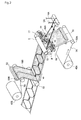
FIG. 2 is a perspective view illustrating the manufacturing method according to the first embodiment of the present invention. -
FIG. 3 is a side view illustrating the manufacturing method according to the first embodiment of the present invention. -
FIG. 4 is a perspective view of a first roll used in the manufacturing method according to the first embodiment of the present invention. -
FIG. 5 is an expanded view of the first roll used in the manufacturing method according to the first embodiment of the present invention. -
FIG. 6 is an expanded view of the first roll used in the manufacturing method according to the first embodiment of the present invention is controlled. - Description will be given with reference to
FIGs. 1A to 6 with regard to the manufacturing method according to the first embodiment of the present invention. -
FIG. 1 (a) is an expanded view of an absorptive article 1 manufactured by the manufacturing method according to the first embodiment of the present invention.FIG. 1(b) is an expanded view of the absorptive article 1 in the process of being manufactured by the manufacturing method according to the first embodiment of the present invention. - Note that, the absorptive article 1 manufactured by the manufacturing method according to the first embodiment of the present invention may be a pants-type disposable diaper or an open-type disposable diaper.
- As shown in
FIG. 1(a) , the absorptive article 1 manufactured by the manufacturing method according to the first embodiment of the present invention includes a liquid-permeable top sheet 6A, a liquid-impermeable back sheet 6B, and anabsorber 12 disposed between thetop sheet 6A and theback sheet 6B. - The absorptive article 1 is provided with leg opening
portions 2, acrotch portion 3, afront waistband portion 15, and arear waistband portion 16. - Here, the absorptive article 1 includes one or more first
elastic member 4 and one or more secondelastic member 5 disposed extending from the leg openingportion 2 to thecrotch portion 3. The first and secondelastic members portion 2. Note that, the absorptive article 1 may be configured to include only any one of the first and secondelastic members portion 2 to thecrotch portion 3. - Also, the absorptive article 1 includes one or more third
elastic members 13 disposed in thefront waistband portion 15, and one or more fourthelastic members 14 disposed in therear waistband portion 16. The third and fourthelastic members - Description will be given below with reference to
FIGs. 1A to 6 with regard to the manufacturing method for the absorptive article 1 according to the first embodiment of the present invention. Specifically, in the manufacturing method for the absorptive article 1 according to the first embodiment of the present invention, description will be given with regard to a step of forming the leg gather to be disposed in the leg openingportion 2 of the absorptive article 1. - Note that, in this manufacturing method, a
first web 7A is continuously transported. Further, the width direction (or CD direction) of afirst web 7A corresponds to the lengthwise direction of the absorptive article 1, and the lengthwise direction (or MD direction) of thefirst web 7A corresponds to the width direction of the absorptive article 1. - As shown in
FIGs. 2 and3 , in a first step, araw fabric 40A of the first web unrolls to dispense thefirst web 7A therefrom, and turns thefirst web 7A around to change its direction by aguide roll 50A. - In a second step, an
adhesive coating apparatus 51 applies a coating of an adhesive 18A to a surface of thefirst web 7A facing asecond web 7B, at its predetermined location. - In a third step, by a first swinging
guide 17 and a second swingingguide 18, respectively, acontinuum 4A of the first elastic member and acontinuum 5A of the second elastic member are placed in a desired layout on at least one surface of thefirst web 7A coated with the adhesive 18A, while swinging thecontinuum 4A of the first elastic member and thecontinuum 5A of the second elastic member in the CD direction of thefirst web 7A (that is, a direction crossing its moving direction). - Here, the desired layout of the first elastic member 4 (that is, the
continuum 4A of the first elastic member) may be different from the desired layout of the second elastic member 5 (that is, thecontinuum 5A of the second elastic member). - In a fourth step, placing the
first web 7A on which thecontinuum 4A of the first elastic member and thecontinuum 5A of the second elastic member are fed, between afirst roll 8, which is rotating in the MD direction, and asecond roll 9. Thecontinuum 4A of the first elastic member, thecontinuum 5A of the second elastic member, and thefirst web 7A can be pressed between thefirst roll 8 and thesecond roll 9. - In a fifth step, an
adhesive coating apparatus 52 applies a coating of an adhesive 18B to a surface of thesecond web 7B, on the surface facing thefirst web 7A, at its predetermined location. Here, thesecond web 7B is dispensed by unrolling a raw fabric of thesecond web 7B. - In a sixth step, by a
roll 53, the surface of thefirst web 7A on which thecontinuum 4A of the first elastic member and thecontinuum 5A of the second elastic member are bonded, and the surface of thesecond web 7B on which the adhesive 18B is applied, are bonded. - In this manner, the
continuum 4A of the first elastic member and thecontinuum 5A of the second elastic member that form the leg gather can be disposed between thefirst web 7A and thesecond web 7B. - Here, as shown in
FIG. 4 , arecess 20 is formed in a predetermined pattern on the outer peripheral surface of thefirst roll 8. Note that, regions other than the recess 20 on the outer peripheral surface of thefirst roll 8 will be hereinafter called asprojections 21A to 21 E. - In the above fourth step, the
continuum 4A of the first elastic member, thecontinuum 5A of the second elastic member, and thefirst web 7A are sandwiched and pressed between thefirst roll 8 and thesecond roll 9. Here, thecontinuum 4A of the first elastic member and thecontinuum 5A of the second elastic member placed in aregion 3A corresponding to the crotch portion on the one surface of thefirst web 7A faces therecess 20 formed in the outer peripheral surface of thefirst roll 8. Also, on the one surface of thefirst web 7A, thecontinuum 4A of the first elastic member and thecontinuum 5A of the second elastic member placed in aregion 2A corresponding to the leg opening portion faces theprojection 21 E formed on the outer peripheral surface of thefirst roll 8. - This makes it is possible to avoid the
continuum 4A of the first elastic member and thecontinuum 5A of the second elastic member placed in theregion 3A corresponding to thecrotch portion 3, from being bonded to the first web and the second web while remaining in the positions X1 and X2 (at which thecontinuums second web - In other words, according to the above-described manufacturing method, by use of the
first roll 8 and thesecond roll 9, thefirst continuum 4A of the first elastic member and thesecond continuum 5A of the second elastic member, which are placed in theregion 2A corresponding to the leg opening portion, can be bonded to the first web and the second web, while remaining in the positions X1 and X2. Concurrently, by use of theroll 53, thefirst continuum 4A of the first elastic member and thesecond continuum 5A of the second elastic member can be bonded to the first web and the second web after being changed into the aligned positions Y1 and Y2. - Referring to
FIGs. 5 and6 , thefirst roll 8 is illustrated in the expanded view by way of example. - In
FIG. 5 , an example is shown in which the outer peripheral length L1 of thefirst roll 8 is substantially equal to the width B of the absorptive article (that is, the pitch distance between products in the MD direction of thefirst web 7A). - In the example shown in
FIG. 5 , an upper half 21 E1 of theprojection 21 E is a portion facing thecontinuum 4A of the first elastic member, and a lower half 21 E2 of theprojection 21 E is a portion facing thecontinuum 5A of the second elastic member. - Note that,
region first roll 8 have therecess 20 formed therein, since these regions are portions facing thecontinuum 4A of the first elastic member and thecontinuum 5A of the second elastic member placed in theregion 3A corresponding to thecrotch portion 3. - More specifically, the
continuum 4A of the first elastic member and thecontinuum 5A of the second elastic member that are placed on theregion 3A corresponding to thecrotch portion 3 need to face therecess 20 formed in the outer peripheral surface of thefirst roll 8, whether thecontinuum 4A of the first elastic member and thecontinuum 5A of the second elastic member are in the positions X1 and X2 or positions Y1 and Y2 inFIG. 1(b) . - Therefore, the
region first roll 8 are formed so that the width Z1 of theregion continuum 4A of the first elastic member in the position X1 and thecontinuum 5A of the second elastic member in the position X2. - In other words, the
recess 20 may be formed in any pattern on the outer peripheral surface of thefirst roll 8, provided only that therecess 20 is formed in theregion - Also, the
projections 21 A to 21 D are provided in order for the first androll 8 and thesecond roll 9 to stably press the continuums therebetween. Here, theprojections projections first roll 8. - On the other hand, in
FIG. 6 , an example is shown in which the outer peripheral length L1 of thefirst roll 8 is substantially half the width B of the absorptive article 1 (that is, the pitch distance between products in the MD direction of thefirst web 7A). - In the example shown in
FIG. 6 , thefirst roll 8 makes two revolutions towards the length B in the width direction of the absorptive article 1, in order to press thecontinuum 4A of the first elastic member and thecontinuum 5A of the second elastic member placed in a product pitch in the MD direction of thefirst web 7A. - In the meantime, a portion of the
first roll 8 facing thecontinuum 4A of the first elastic member shifts in the order of; a projection 21 F1, arecess 20C, arecess 20D, and a projection 21 F4. Meanwhile, a portion of thefirst roll 8 while facing thecontinuum 5A of the second elastic member shifts in the order of: a projection 21 F3, therecess 20C, therecess 20D, and a projection 21 F2. - Note that, the
regions first roll 8 have therecess 20 formed therein, since these regions are the portions facing thecontinuum 4A of the first elastic member and thecontinuum 5A of the second elastic member placed in theregion 3A corresponding to thecrotch portion 3. - In other words, the
recess 20 may be formed in any pattern on the outer peripheral surface of thefirst roll 8, provided only that therecess 20 is formed in theregions - Also, the outer peripheral surface of the
first roll 8 may be provided with theprojections 21 A to 21 D (not shown) in order for thefirst roll 8 and thesecond roll 9 to stably press the continuums therebetween. - Note that, it may be configured that the
first roll 8 is a driven roll and thesecond roll 9 is a non-driven roll. Alternatively, it may be configured that both of thefirst roll 8 and thesecond roll 9 are driven rolls. - Also, the
recess 20 may be formed in the predetermined pattern on the outer peripheral surface of thesecond roll 9, as in the case of the outer peripheral surface of thefirst roll 8. - Also, an anti-adhesion process may be applied on the outer peripheral surface of the
second roll 9, in order to prevent the adhesive 18A which is coated on thefirst web 7A, from adhering onto the outer peripheral surface of thesecond roll 9. - For example, the anti-adhesion process on the outer peripheral surface of the
second roll 9 can be performed by covering the outer peripheral surface of thesecond roll 9 with a secondnon-adhesive member 10. Here, the secondnon-adhesive member 10 is replaceable. As an example of the anti-adhesion process, the silicone rubber or the like may be used. Further, as an example of the secondnon-adhesive member 10, an adhesive tape having an anti-adhesive process, or the like may be used. - Also, the anti-adhesion process may be likewise applied on the outer peripheral surface of the
first roll 8. For example, the anti-adhesion process on the outer peripheral surface of thefirst roll 8 can be performed by covering the outer peripheral surface of thefirst roll 8 with a first non-adhesive member. Here, the first non-adhesive member is replaceable - Also, the above-described manufacturing method may further include a step of cooling the
second roll 9. Here, it is preferable that the thickness of the above-mentioned secondnon-adhesive member 10 be less than the thickness of the above-mentioned first non-adhesive member in order to improve the effect of cooling of thesecond roll 9. - According to the absorptive article of the first embodiment of the present invention, the
recess 20 is formed so as to face theregion 3A corresponding to thecrotch portion 3 on the outer peripheral surface of thefirst roll 8. Accordingly, by use of thefirst roll 8 and thesecond roll 9, thecontinuum 4A of the first elastic member and thecontinuum 5A of the second elastic member placed in theregion 2A corresponding to theleg opening portion 2, can be bonded to the first web and the second web, while remaining in the positions at which thecontinuums second web roll 53, thecontinuum 4A of the first elastic member and thecontinuum 5A of the second elastic member placed in theregion 3A corresponding to thecrotch portion 3 can be bonded to thefirst web 7A and thesecond web 7B, after being displaced to their aligned positions Y1 and Y2. - According to the absorptive article of the first embodiment of the present invention, by setting the outer peripheral length of the
first roll 8 shorter than the width B of the absorptive article 1, a space can be formed in the vicinity of a point at which thefirst roll 8 and thesecond roll 9 are pressed to each other. Thereby, the first swingingguide 17 and the second swingingguide 18 can be brought close to a point at which thefirst roll 8 and thesecond roll 9 are pressed to each other, and thus, the desired layout can be arranged in a form close to the locus of the first swingingguide 17 and the second swingingguide 18. - According to the absorptive article according to the first embodiment of the present invention, the
second roll 9 may be the non-driven roll. At this time, thesecond roll 9 rotates twice in accordance with the feeding speed of thefirst web 7A and thesecond web 7B. Accordingly, even when the peripheral speed is changed in any of thefirst roll 8 and thesecond roll 9 owing to the wearing or the like, the changes in the peripheral speed of thefirst roll 8 and thesecond roll 9 can be accommodated. - According to the absorptive article of the first embodiment of the present invention, the
first roll 8, that is the roll having therecess 20 formed therein, may be the driven roll. This makes it possible to adjust and eliminate a misalignment between the predetermined pattern of therecess 20 and the desired layout of the placement of thecontinuum 4A of the first elastic member and thecontinuum 5A of the second elastic member. - According to the absorptive article of the first embodiment of the present invention, the manufacturing method may include the step of cooling the
second roll 9. This makes it possible to achieve the effect of hardening the adhesive 18A coated on thefirst web 7A, and the effect of allowing heat to escape from the adhesive 18A. - In other words, on the
first web 7A, the adhesive 18A that is coated on theportion facing recess 20 is not cooled, thereby taking a long time to be hardened. Meanwhile, the adhesive 18A that is coated on the portion facing the projection 21 is cooled, thereby taking a short time to be hardened. Accordingly, thecontinuum 4A of the first elastic member and thecontinuum 5A of the second elastic member are easily displaced to the aligned positions Y1 and Y2. - According to the absorptive article of the first embodiment of the present invention, the anti-adhesion process may be applied on the outer peripheral surface of the
second roll 9. Accordingly, the adhesive 18A coated on thefirst web 7A can be prevented from adhering onto the outer peripheral surface of thesecond roll 9. - According to the absorptive article of the first embodiment of the present invention, the thickness of the above-mentioned second
non-adhesive member 10 may be less than the thickness of the above-mentioned first non-adhesive member. Accordingly, the above-mentioned effect of cooling thesecond roll 9 can be further improved. - According to the absorptive article of the first embodiment of the present invention, the anti-adhesion process on the outer peripheral surface of the
second roll 9 may be performed by covering the outer peripheral surface of thesecond roll 9 with the secondnon-adhesive member 10, which is replaceable. Thereby, when the outer peripheral surface of thesecond roll 9 is worn out, it only needs to replace the secondnon-adhesive member 10, and thesecond roll 9 in itself does not need to be replaced. Accordingly, the cost for replacing thesecond roll 9 in itself can be reduced. - In other words, when the
second roll 9 is a flat roll having no recess formed therein, it is not required to replace the outer peripheral surface of the roll having therecess 20 formed therein, such as thefirst roll 8. - In the above-mentioned embodiment, the
first web 7A and thesecond web 7B are bonded together, after thefirst web 7A is bonded with thecontinuum 4A of the first elastic member and thecontinuum 5A of the second elastic member and second elastic member, respectively. However, the present invention is not limited to the foregoing. - The leg gather may be formed for example by performing the following steps.
- In a first step, the
raw fabric 40A of the first web is unrolled to dispense thefirst web 7A therefrom, and thefirst web 7A is turned around to change its direction by theguide roll 50A. At the same time, theraw fabric 40B of the second web is also unrolled to dispense thesecond web 7B therefrom, and thesecond web 7B is turned around to change its direction by aguide roll 50B. - In a second step, the
adhesive coating apparatus 51 applies a coating of the adhesive 18A to the surface of thefirst web 7A facing thesecond web 7B, at its predetermined location. At the same time, theadhesive coating apparatus 52 applies a coating of the adhesive 18B to the surface of thesecond web 7B facing thefirst web 7A, at its predetermined location. - In a third step, the
continuum 4A of the first elastic member is placed in the desired layout on the surface of thefirst web 7A coated with the adhesive 18A, while thecontinuum 4A of the first elastic member is swung by the first swingingguide 17, in the CD direction of thefirst web 7A (that is, the direction crossing its moving direction). At the same time, thecontinuum 5A of the second elastic member is placed in the desired layout on the surface of thesecond web 7B coated with the adhesive 18B, while thecontinuum 5A of the second elastic member is swung by the second swingingguide 18, in the CD direction of thesecond web 7B (that is, the direction crossing its moving direction). - Here, the desired layout of the first elastic member 4 (that is, the
continuum 4A of the first elastic member) may be different from the desired layout of the second elastic member 5 (that is, thecontinuum 5A of the second elastic member). - In a fourth step, the
first web 7A on which thecontinuum 4A of the first elastic member is placed thereon and thesecond web 7B on which thecontinuum 5A of the second elastic member is placed are placed between thefirst roll 8, which is rotating in the MD direction, and thesecond roll 9. By use of thefirst roll 8 and thesecond roll 9, thecontinuum 4A of the first elastic member, thecontinuum 5A of the second elastic member, thefirst web 7A, and thesecond web 7B can be sandwiched and pressed between thefirst roll 8 and thesecond roll 9. - In this manner, the
continuum 4A of the first elastic member and thecontinuum 5A of the second elastic member, which form the leg gather, can be disposed between thefirst web 7A and thesecond web 7B. - While the invention has been described in detail above with reference to the above-mentioned embodiments, it should be apparent to those skilled in the art that this invention is not limited to the embodiments described herein. The invention may be practiced in the form of modifications and variations without departing from the basic concept and scope of the invention as defined in the appended claims. It is to be therefore understood that the disclosure herein is for purposes of illustration only and is not intended to limit the scope of the invention.
- Note that the entire contents of Japanese Patent Application No.
2008-165293 (filed on June 25, 2008 - The present invention is useful in manufacturing method for an absorptive article since it is possible to provide a manufacturing method for an absorptive article, which can properly bond the elastic member to the web, in the region corresponding to the crotch portion.
Claims (8)
- A manufacturing method for an absorptive article provided with a leg opening portion and a crotch portion and having an elastic member disposed extending from the leg opening portion to the crotch portion, comprising:placing a continuum of the elastic member in a desired layout, on at least one surface of a web being transported continuously, while swinging the continuum of the elastic member in a direction crossing a moving direction of the web;feeding the web on which the continuum of the elastic member is placed, between a first roll, which is rotating in the moving direction, and a second roll; andpressing the continuum of the elastic member and the web between the first roll and the second roll, whereina recess is formed in a predetermined pattern on at least an outer peripheral surface of the first roll, andthe continuum of the elastic member and the web are pressed between the first roll and the second roll while the continuum of the elastic member placed in an area corresponding to the crotch portion on one surface of the web faces the recess formed on the outer peripheral surface of the first roll.
- The manufacturing method for an absorptive article according to claim 1, wherein an outer peripheral length of the first roll is approximately equal to or substantially half of the absorptive article in its width direction.
- The manufacturing method for an absorptive article according to any of claims 1 and 2, wherein the first roll is a driven roll, and the second roll is a non-driven roll.
- The manufacturing method for an absorptive article according to any one of claims 1 to 3, further comprising: cooling the second roll.
- The manufacturing method for an absorptive article according to any one of claims 1 to 4, wherein an anti-adhesion process is applied on at least an outer peripheral surface of the second roll.
- The manufacturing method for an absorptive article according to claim 4, wherein
an anti-adhesion process is applied on the outer peripheral surface of the second roll, by covering at least the outer peripheral surface of the second roll with a second non-adhesive member which is replaceable. - The manufacturing method for an absorptive article according to claim 6, wherein
the anti-adhesion process is applied on the outer peripheral surface of the first roll, by covering the outer peripheral surface of the first roll with a first non-adhesive member which is replaceable, and
a thickness of the second non-adhesive member is less than a thickness of the first non-adhesive member. - The manufacturing method for an absorptive article according to any one of claims 1 to 7, wherein
the elastic member includes a first elastic member and a second elastic member, and
a desired layout of the first elastic member is different from a desired layout of the second elastic member.
Applications Claiming Priority (2)
| Application Number | Priority Date | Filing Date | Title |
|---|---|---|---|
| JP2008165293A JP5385556B2 (en) | 2008-06-25 | 2008-06-25 | Method for manufacturing absorbent article |
| PCT/JP2009/061357 WO2009157421A1 (en) | 2008-06-25 | 2009-06-23 | Method for manufacturing absorbent article |
Publications (2)
| Publication Number | Publication Date |
|---|---|
| EP2322125A1 true EP2322125A1 (en) | 2011-05-18 |
| EP2322125A4 EP2322125A4 (en) | 2013-02-20 |
Family
ID=41444487
Family Applications (1)
| Application Number | Title | Priority Date | Filing Date |
|---|---|---|---|
| EP09770131A Withdrawn EP2322125A4 (en) | 2008-06-25 | 2009-06-23 | Method for manufacturing absorbent article |
Country Status (18)
| Country | Link |
|---|---|
| US (1) | US8221572B2 (en) |
| EP (1) | EP2322125A4 (en) |
| JP (1) | JP5385556B2 (en) |
| KR (1) | KR101425702B1 (en) |
| CN (1) | CN102076294B (en) |
| AR (1) | AR072299A1 (en) |
| AU (1) | AU2009263388B2 (en) |
| CA (1) | CA2728956A1 (en) |
| CO (1) | CO6341538A2 (en) |
| EA (1) | EA018819B1 (en) |
| MA (1) | MA32489B1 (en) |
| MX (1) | MX2009006951A (en) |
| MY (1) | MY152019A (en) |
| NZ (1) | NZ590438A (en) |
| RU (1) | RU2399368C2 (en) |
| TW (1) | TW201014581A (en) |
| WO (1) | WO2009157421A1 (en) |
| ZA (1) | ZA201100511B (en) |
Families Citing this family (10)
| Publication number | Priority date | Publication date | Assignee | Title |
|---|---|---|---|---|
| US20100193138A1 (en) * | 2009-01-30 | 2010-08-05 | Joseph Allen Eckstein | System for High-Speed Continuous Application of a Strip Material to a Moving Sheet-Like Substrate Material at Laterally Shifting Locations |
| JP5396321B2 (en) * | 2010-03-26 | 2014-01-22 | ユニ・チャーム株式会社 | Absorber manufacturing equipment |
| US10993849B2 (en) | 2010-09-16 | 2021-05-04 | Dsg Technology Holdings Ltd. | Article with chassis having an elastic distribution, absorbent core and system and method for making same |
| CA2812185C (en) | 2010-09-16 | 2021-03-02 | Dsg Technology Holdings Ltd | Article with elastic distribution and system and method for making same |
| CN103201097B (en) * | 2010-10-28 | 2015-10-14 | 花王株式会社 | The manufacture method of Stretchable sheet |
| JP5089751B2 (en) * | 2010-10-28 | 2012-12-05 | 花王株式会社 | Method for producing elastic sheet |
| KR101264517B1 (en) * | 2011-02-18 | 2013-05-14 | 삼성에스디아이 주식회사 | Laminating apparatus for electrode substrate |
| CN107847368A (en) | 2015-02-26 | 2018-03-27 | 瑞德科技控股有限公司 | Disposable absorbent core and disposable absorbent assembly including same and method of manufacture |
| JP6359071B2 (en) * | 2016-11-25 | 2018-07-18 | 大王製紙株式会社 | Trunks type disposable diaper |
| US10925776B2 (en) | 2016-12-22 | 2021-02-23 | Dsg Technology Holdings Ltd. | Disposable floating absorbent core and disposable absorbent assembly including same, and method of making same |
Family Cites Families (18)
| Publication number | Priority date | Publication date | Assignee | Title |
|---|---|---|---|---|
| FR2112075B1 (en) * | 1970-09-18 | 1973-12-07 | Elastelle Fontanille Il | |
| JPH0611275B2 (en) * | 1989-06-29 | 1994-02-16 | ユニ・チャーム株式会社 | Disposable brief manufacturing method |
| JP2757932B2 (en) * | 1993-05-26 | 1998-05-25 | 株式会社日本吸収体技術研究所 | Tapeless absorber product and method of manufacturing the same |
| JP3086141B2 (en) * | 1994-11-10 | 2000-09-11 | 花王株式会社 | Oscillation bonding method for elastic members |
| US6336543B1 (en) * | 1998-04-22 | 2002-01-08 | Wilbur C. Thomas | Method for forming a replaceable roll covering and apparatus |
| US6387471B1 (en) * | 1999-03-31 | 2002-05-14 | Kimberly-Clark Worldwide, Inc. | Creep resistant composite elastic material with improved aesthetics, dimensional stability and inherent latency and method of producing same |
| PL365887A1 (en) * | 2000-12-20 | 2005-01-10 | Kimberly-Clark Worldwide, Inc. | Thin, high capacity absorbent structure and method for producing same |
| JP3561477B2 (en) * | 2001-03-16 | 2004-09-02 | 大王製紙株式会社 | Method for manufacturing elastic sheet |
| US6845283B2 (en) * | 2002-07-26 | 2005-01-18 | Kimberly-Clark Worldwide, Inc. | Process and apparatus for making articles |
| US7097725B2 (en) * | 2002-10-16 | 2006-08-29 | Zuiko Corporation | Placement device |
| JP2004155586A (en) * | 2002-10-16 | 2004-06-03 | Zuiko Corp | Placement device |
| JP4205400B2 (en) * | 2002-11-12 | 2009-01-07 | ユニ・チャーム株式会社 | Method and apparatus for attaching an elastic member to a disposable worn article produced continuously |
| JP4208625B2 (en) * | 2003-03-31 | 2009-01-14 | 花王株式会社 | Absorbent article and manufacturing method thereof |
| JP3645248B2 (en) * | 2003-08-05 | 2005-05-11 | ユニ・チャーム株式会社 | Disposable diapers |
| JP4698208B2 (en) * | 2004-11-18 | 2011-06-08 | 花王株式会社 | Disposable diaper manufacturing method |
| JP4551800B2 (en) * | 2005-03-28 | 2010-09-29 | 大王製紙株式会社 | Pants-type disposable diaper |
| JP2006312525A (en) * | 2005-05-09 | 2006-11-16 | Livedo Corporation | Carrying device and carrying method of thread-like elastic member |
| JP2008165293A (en) | 2006-12-27 | 2008-07-17 | Seiko Epson Corp | Data search apparatus, device management apparatus, data search method, and computer program |
-
2008
- 2008-06-25 JP JP2008165293A patent/JP5385556B2/en not_active Expired - Fee Related
- 2008-08-22 RU RU2008134331/11A patent/RU2399368C2/en not_active IP Right Cessation
-
2009
- 2009-02-20 US US12/390,068 patent/US8221572B2/en not_active Expired - Fee Related
- 2009-06-23 CA CA2728956A patent/CA2728956A1/en not_active Abandoned
- 2009-06-23 EP EP09770131A patent/EP2322125A4/en not_active Withdrawn
- 2009-06-23 MY MYPI20106165 patent/MY152019A/en unknown
- 2009-06-23 WO PCT/JP2009/061357 patent/WO2009157421A1/en not_active Ceased
- 2009-06-23 AU AU2009263388A patent/AU2009263388B2/en not_active Ceased
- 2009-06-23 CN CN2009801238353A patent/CN102076294B/en not_active Expired - Fee Related
- 2009-06-23 EA EA201100100A patent/EA018819B1/en not_active IP Right Cessation
- 2009-06-23 NZ NZ590438A patent/NZ590438A/en unknown
- 2009-06-23 KR KR1020107028846A patent/KR101425702B1/en not_active Expired - Fee Related
- 2009-06-24 AR ARP090102328A patent/AR072299A1/en unknown
- 2009-06-25 TW TW098121387A patent/TW201014581A/en unknown
- 2009-06-25 MX MX2009006951A patent/MX2009006951A/en active IP Right Grant
-
2011
- 2011-01-19 MA MA33536A patent/MA32489B1/en unknown
- 2011-01-20 ZA ZA2011/00511A patent/ZA201100511B/en unknown
- 2011-01-24 CO CO11007192A patent/CO6341538A2/en active IP Right Grant
Also Published As
| Publication number | Publication date |
|---|---|
| US8221572B2 (en) | 2012-07-17 |
| NZ590438A (en) | 2012-09-28 |
| MX2009006951A (en) | 2010-02-19 |
| AU2009263388A1 (en) | 2009-12-30 |
| EA018819B1 (en) | 2013-10-30 |
| EP2322125A4 (en) | 2013-02-20 |
| JP2010004973A (en) | 2010-01-14 |
| MA32489B1 (en) | 2011-07-03 |
| EA201100100A1 (en) | 2011-08-30 |
| CN102076294B (en) | 2013-06-05 |
| US20090320993A1 (en) | 2009-12-31 |
| RU2399368C2 (en) | 2010-09-20 |
| RU2008134331A (en) | 2010-02-27 |
| KR101425702B1 (en) | 2014-08-01 |
| WO2009157421A1 (en) | 2009-12-30 |
| CO6341538A2 (en) | 2011-11-21 |
| MY152019A (en) | 2014-08-15 |
| TW201014581A (en) | 2010-04-16 |
| AR072299A1 (en) | 2010-08-18 |
| CN102076294A (en) | 2011-05-25 |
| ZA201100511B (en) | 2012-01-25 |
| JP5385556B2 (en) | 2014-01-08 |
| AU2009263388B2 (en) | 2013-12-19 |
| CA2728956A1 (en) | 2009-12-30 |
| KR20110031924A (en) | 2011-03-29 |
Similar Documents
| Publication | Publication Date | Title |
|---|---|---|
| AU2009263388B2 (en) | Manufacturing method for absorptive article | |
| EP2356960B1 (en) | Device for manufacturing absorptive article and method of manufacturing absorptive article | |
| EP2186493B1 (en) | Method of manufacturing disposable diaper | |
| EP2621437B1 (en) | Pants-type diaper | |
| US9295590B2 (en) | Method and apparatus for applying an elastic material to a moving substrate in a curved path | |
| EP2925261B1 (en) | Methods and apparatus for applying adhesives in patterns to an advancing substrate | |
| EP3257488B1 (en) | Method and device for manufacturing sheet member for absorptive articles | |
| US8349117B2 (en) | Absorbent wearing article and process of making the same | |
| KR101621583B1 (en) | Manufacturing method of composite sheet and manufacturing device | |
| EP2403456B1 (en) | Apparatus and method for manufacturing absorbent article | |
| WO2013080782A1 (en) | Disposable nappy and method for manufacturing extendible sheet | |
| KR20150003242A (en) | Disposable diaper and method for producing disposable diaper | |
| JP5859918B2 (en) | Absorbent article manufacturing apparatus and absorbent article manufacturing method | |
| EP3326596B1 (en) | Method of making wearable article comprising elastic belt | |
| CN103501744B (en) | There is the bar tape processing unit of central branches pushing out ring and use the method for this device | |
| KR102070473B1 (en) | Composite stretchable material | |
| US11166859B2 (en) | Method of making wearable article comprising elastic belt | |
| US8535468B2 (en) | Method for making disposable bodily fluid handling composite pad | |
| US12616614B2 (en) | Absorbent articles with corrugated elastomeric laminates and methods for making corrugated elastomeric laminates | |
| US20250345213A1 (en) | Methods and apparatuses for making absorbent articles with elastomeric laminates having been accumulated and refreshed | |
| CN120344220A (en) | Elastic cover for wearable article and method of making the same |
Legal Events
| Date | Code | Title | Description |
|---|---|---|---|
| PUAI | Public reference made under article 153(3) epc to a published international application that has entered the european phase |
Free format text: ORIGINAL CODE: 0009012 |
|
| 17P | Request for examination filed |
Effective date: 20110121 |
|
| AK | Designated contracting states |
Kind code of ref document: A1 Designated state(s): AT BE BG CH CY CZ DE DK EE ES FI FR GB GR HR HU IE IS IT LI LT LU LV MC MK MT NL NO PL PT RO SE SI SK TR |
|
| AX | Request for extension of the european patent |
Extension state: AL BA RS |
|
| DAX | Request for extension of the european patent (deleted) | ||
| A4 | Supplementary search report drawn up and despatched |
Effective date: 20130123 |
|
| RIC1 | Information provided on ipc code assigned before grant |
Ipc: A61F 13/49 20060101ALI20130117BHEP Ipc: A61F 13/15 20060101AFI20130117BHEP |
|
| 17Q | First examination report despatched |
Effective date: 20140321 |
|
| STAA | Information on the status of an ep patent application or granted ep patent |
Free format text: STATUS: THE APPLICATION IS DEEMED TO BE WITHDRAWN |
|
| 18D | Application deemed to be withdrawn |
Effective date: 20140801 |