EP2321156B1 - Inflator for an airbag - Google Patents
Inflator for an airbag Download PDFInfo
- Publication number
- EP2321156B1 EP2321156B1 EP09811928A EP09811928A EP2321156B1 EP 2321156 B1 EP2321156 B1 EP 2321156B1 EP 09811928 A EP09811928 A EP 09811928A EP 09811928 A EP09811928 A EP 09811928A EP 2321156 B1 EP2321156 B1 EP 2321156B1
- Authority
- EP
- European Patent Office
- Prior art keywords
- airbag
- gas
- inflator
- gas generant
- temperature
- Prior art date
- Legal status (The legal status is an assumption and is not a legal conclusion. Google has not performed a legal analysis and makes no representation as to the accuracy of the status listed.)
- Active
Links
Images


Classifications
-
- B—PERFORMING OPERATIONS; TRANSPORTING
- B60—VEHICLES IN GENERAL
- B60R—VEHICLES, VEHICLE FITTINGS, OR VEHICLE PARTS, NOT OTHERWISE PROVIDED FOR
- B60R21/00—Arrangements or fittings on vehicles for protecting or preventing injuries to occupants or pedestrians in case of accidents or other traffic risks
- B60R21/02—Occupant safety arrangements or fittings, e.g. crash pads
- B60R21/16—Inflatable occupant restraints or confinements designed to inflate upon impact or impending impact, e.g. air bags
- B60R21/26—Inflatable occupant restraints or confinements designed to inflate upon impact or impending impact, e.g. air bags characterised by the inflation fluid source or means to control inflation fluid flow
-
- B—PERFORMING OPERATIONS; TRANSPORTING
- B60—VEHICLES IN GENERAL
- B60R—VEHICLES, VEHICLE FITTINGS, OR VEHICLE PARTS, NOT OTHERWISE PROVIDED FOR
- B60R21/00—Arrangements or fittings on vehicles for protecting or preventing injuries to occupants or pedestrians in case of accidents or other traffic risks
- B60R21/02—Occupant safety arrangements or fittings, e.g. crash pads
- B60R21/16—Inflatable occupant restraints or confinements designed to inflate upon impact or impending impact, e.g. air bags
- B60R21/26—Inflatable occupant restraints or confinements designed to inflate upon impact or impending impact, e.g. air bags characterised by the inflation fluid source or means to control inflation fluid flow
- B60R21/261—Inflatable occupant restraints or confinements designed to inflate upon impact or impending impact, e.g. air bags characterised by the inflation fluid source or means to control inflation fluid flow with means other than bag structure to diffuse or guide inflation fluid
- B60R21/262—Elongated tubular diffusers, e.g. curtain-type
-
- B—PERFORMING OPERATIONS; TRANSPORTING
- B60—VEHICLES IN GENERAL
- B60R—VEHICLES, VEHICLE FITTINGS, OR VEHICLE PARTS, NOT OTHERWISE PROVIDED FOR
- B60R21/00—Arrangements or fittings on vehicles for protecting or preventing injuries to occupants or pedestrians in case of accidents or other traffic risks
- B60R21/02—Occupant safety arrangements or fittings, e.g. crash pads
- B60R21/16—Inflatable occupant restraints or confinements designed to inflate upon impact or impending impact, e.g. air bags
- B60R21/26—Inflatable occupant restraints or confinements designed to inflate upon impact or impending impact, e.g. air bags characterised by the inflation fluid source or means to control inflation fluid flow
- B60R2021/26029—Ignitors
-
- B—PERFORMING OPERATIONS; TRANSPORTING
- B60—VEHICLES IN GENERAL
- B60R—VEHICLES, VEHICLE FITTINGS, OR VEHICLE PARTS, NOT OTHERWISE PROVIDED FOR
- B60R21/00—Arrangements or fittings on vehicles for protecting or preventing injuries to occupants or pedestrians in case of accidents or other traffic risks
- B60R21/02—Occupant safety arrangements or fittings, e.g. crash pads
- B60R21/16—Inflatable occupant restraints or confinements designed to inflate upon impact or impending impact, e.g. air bags
- B60R21/26—Inflatable occupant restraints or confinements designed to inflate upon impact or impending impact, e.g. air bags characterised by the inflation fluid source or means to control inflation fluid flow
- B60R21/268—Inflatable occupant restraints or confinements designed to inflate upon impact or impending impact, e.g. air bags characterised by the inflation fluid source or means to control inflation fluid flow using instantaneous release of stored pressurised gas
- B60R21/274—Inflatable occupant restraints or confinements designed to inflate upon impact or impending impact, e.g. air bags characterised by the inflation fluid source or means to control inflation fluid flow using instantaneous release of stored pressurised gas characterised by means to rupture or open the fluid source
Definitions
- the present disclosure generally relates to pyrotechnic inflators for airbags.
- Airbags can typically include an inflator that can be connected to the one or more airbags positioned within the vehicle, and can rapidly produce a quantity of inflation fluid or gas that can fill the airbag(s) to protect the occupant(s).
- a vehicle can include an inflatable curtain airbag.
- the inflatable curtain airbag can be deployed from a headliner of the vehicle, and can inflate to protect the head of the occupant(s) from contact with the side of the vehicle, such as the windows.
- Certain inflatable curtain airbags such as those designed to withstand mostly a lateral impact event, may utilize a "hot gas" inflator since cooling of the gas and the resulting loss of airbag pressure may not be an issue due to the short duration of the event.
- Other inflatable curtain airbags, such as those designed to withstand a rollover event can generally use "cold gas" inflators to meet the extended pressure requirements.
- the inflator can include a housing having a first end and a second end and defining a cavity.
- the inflator can also include a gas generant disposed in the housing for producing a combustion gas to inflate the airbag.
- the gas generant can define a bore.
- the inflator can also include a temporary closure for temporarily sealing the cavity.
- the inflator can include an igniter for igniting the gas generant to produce the combustion gas and for generating a shockwave to propogate through the bore and open the temporary closure.
- the inflator in combination with an airbag.
- the inflator can include a housing that defines a cavity, and has a first end and a second end.
- the inflator can also include a compressed gas normally retained within the chamber at a first temperature.
- the inflator can include a gas generant of a combustible material disposed in the chamber, and the gas generant can define a throughbore.
- the inflator can also include a temporary closure that seals the cavity from the airbag prior to inflation of the airbag.
- the inflator can further include an igniter disposed within the housing that opens the temporary closure to allow release of at least a portion of the compressed gas at a first temperature from the cavity to the airbag. The igniter can be further operative to ignite the gas generant for generating a combustion gas at a second temperature.
- the method can include igniting a reactive charge upon receipt of a signal.
- the method can also include opening a temporary closure with a shockwave created by the ignition of the reactive charge.
- the method can also include propogating the reactive charge through a bore extending through a gas generant to open the temporary closure.
- the method can further include igniting the gas generate.
- the method can include inflating the airbag with a gas that passes through an opening created by opening the temporary closure.
- Fig. 1 is a schematic illustration of an exemplary motor vehicle including an inflator for inflating an airbag according to the principles of the present disclosure, the airbag shown in a first or deployed position;
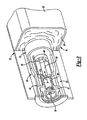
- Fig. 2 is a partially cut-away illustration of the inflator of Fig. 1 , shown operatively associated with the airbag, the airbag shown in a second or stowed position;
- Fig. 3 is a detailed sectional view of the inflator of Fig. 1 .
- the airbag system 12 can include an airbag 16 and an inflator 18.
- the airbag 16 can include a cushion 20, which can be stored within a trim panel 22 of the motor vehicle 10.
- the airbag 16 can comprise a side impact inflatable curtain airbag, which when inflated by the inflator 18 can occupy a large volume of a passenger cabin 10a in the motor vehicle 10 as illustrated in Fig. 1 .
- the inflator 18 can create a rapidly expanding gas that can inflate the airbag 16 within milliseconds of detection of a predetermined event (e.g., impending vehicle rollover) of the motor vehicle 10 to enable the airbag 16 to inflate and create a barrier between occupant(s) of the motor vehicle 10 and the motor vehicle 10 itself, which may prevent or minimize injuries to the occupant(s).
- a predetermined event e.g., impending vehicle rollover
- the inflator 18 can include a housing 30, an igniter system 32 and a closure member in the form of a rupturable gas outlet membrane or burst disk 34 ( Fig. 3 ).
- the housing 30 can be cylindrical, and can have a generally circular cross section.
- the housing 30 can be composed of a metal or metal alloy, such as steel, magnesium alloy, etc., and can be formed through any suitable method, such as stamping, machining, casting, extrusion, etc. With reference to the environmental view of Fig. 1 , it should be noted that although the housing 30 is illustrated as having a particular length relative to the vehicle 10, the housing 30 could have any suitable length.
- the housing 30 can have a first end 36, a second end 38 and can define an intermediate portion defining a cavity 42.
- the first end 36 can be coupled to the igniter system 32.
- the second end 38 can define an outlet 38a.
- the outlet 38a can be in communication with the airbag 16 to enable gases within the housing 30 to inflate the airbag 16.
- the burst disk 34 defines a temporary closure for the housing 30 that can be positioned over the outlet 38a to control the inflation of the airbag 16.
- the cavity 42 can generally extend from the first end 36 to the second end 38, and can store a compressed gas.
- the cavity 42 can be configured to store the compressed gas at a pressure from about 6500 pounds per square inch to about 8500 pounds per square inch, for example. This pressure may vary, however, for particular applications.
- the igniter system 32 can include an initiator 44 and a gas generant 45.
- the initiator 44 can comprise any suitable initiator, such as that disclosed in commonly assigned U.S. Patent No. 7,210,703 , incorporated herein by reference in its entirety, the initiator 44 will not be discussed in detail herein. Briefly, however, the initiator 44 can include a squib 46, a reactive charge 47, a dome or cap 48, a first conductive pin 50, a second conductive pin 52 and a bridgewire (not specifically shown).
- the squib 46 can produce a detonation or ignition charge upon receipt of an electrical signal, such as an electrical current, as will be discussed.
- the reactive charge 47 can be contained within a charge chamber 47a, and can be in communication with and responsive to the squib 46 to detonate or ignite upon receipt of the charge from the squib 46.
- the detonation of the reactive charge 47 can create a shockwave, which can radiate away from the reactive charge 47 in a direction generally indicated by the arrow A.
- the shockwave A can rupture the cap 48, and can pass through the gas generant 45, as will be discussed herein.
- the cap 48 Prior to activation of the reactive charge 47, the cap 48 can seal the gas generant 45 and the chamber 40 of the housing 30 from the initiator 44. Generally, the cap 48 can be positioned between the initiator 44 and the generant 45.
- the first conductive pin 50 can be isolated from the squib 46, while the second conductive pin 52 can be coupled to the squib 46.
- the bridgewire can connect the first conductive pin 50 to the second conductive pin 52. Additional reactive charge 47 can also be packed about the bridgewire, if desired.
- an electric current can be introduced to the first conductive pin 50 and the second conductive pin 52. The introduction of the electric current can cause the squib 46 to fire, and produce a detonation or ignition charge, which in turn, can detonate the reactive charge 47 to create the shockwave A.
- the reactive charge 47 can ignite the gas generant 45 after at least a portion of the shockwave A passes through a bore 56 defined in the gas generant 45.
- the gas generant 45 can comprise any material suitable for generating sufficient combustion gases to inflate the airbag 16.
- the gas generant 45 can be a solid grain that comprises a pyrotechnic material.
- the gas generant 45 can comprise a monolithic gas generant grain. Examples of suitable gas generants are described in commonly owned U.S. Serial No. 11/472,260 filed 21 June 2006 , which is hereby incorporated by reference as if fully set forth herein. It will be understood, however, that other gas generants may be employed within the scope of the present teachings.
- the gas generant 45 can generally be formed into one or more cylindrical structures. It should be understood, however, that although the gas generant 45 can have any desired shape, so long as propogation of the shockwave A is provided. The gas generant 45 can be held in place with a plug 49, if desired. The gas generant 45 can generally be ignited by the detonation of the reactive charge 47.
- the bore 56 can generally be formed or defined about a longitudinal axis defined by the gas generant 45, and the gas generant 45 can be positioned proximate to the cap 48 of the initiator 44 such that at least a portion of the shockwave A can travel through the bore 56.
- the bore 56 can have any desired shape, but can generally have a circular cross-section.
- the bore 56 can be of any suitable size to enable the transmission of a sufficient shockwave A to open the temporary closure or burst disk 34.
- the bore 56 can have a diameter from about 4.5 millimeters to about 9.0 millimeters.
- the diameter of the bore 56 can be proportional to a diameter of the gas generant 45, and thus, the diameter of the bore 56 may increase or decrease depending upon the diameter of the gas generant 45.
- the passage of at least a portion of the shockwave A through the gas generant 45 can rupture the burst disk 34.
- the burst disk 34 can comprise any rupturable device or other temporary closure device that can be positioned over the outlet 38a of the second end 38 of the housing 30.
- the burst disk 34 can include one or more scored seams to facilitate the rupturing of the burst disk 34.
- the burst disk 34 can generally be rupturable to open to enable the compressed gas to exit the cavity 42 of the inflator 18 and inflate the airbag 16.
- the shockwave A can initially rupture the burst disk 34
- at least a portion of the compressed gas at a first temperature can enter the airbag 16 for initially inflating the airbag 16.
- the first temperature can generally comprise the ambient, unheated temperature of the compressed gas within the cavity 42.
- a combustion gas is generated that has a second temperature or increased temperature. The heated combustion gas can pass through the outlet 38a to further inflate the airbag 16.
- the inflator 18 can be used to quickly inflate a large volume airbag 16, such as a side curtain airbag.
- a signal in the form of an electric current can trigger the initiator 44, causing the squib 46 to detonate the reactive charge 47.
- the detonation of the reactive charge 47 can create the shockwave A.
- the shockwave A can rupture the cap 48, and can pass through the bore 56 defined in the gas generant 45 to rupture the burst disk 34 ( Fig. 3 ).
- the burst disk 34 ruptures, at least a portion of the compressed gas stored within the chamber 40 can pass through the outlet 38a of the second end 38 of the housing 30.
- the compressed gas that initially flows through the outlet 38a to inflate the airbag 16 can be unheated, "cold" or at a first temperature, the initial impact pressures on the airbag 16 can be minimized, which in turn can decrease the potential damage to the airbag 16.
- the inflator 18 can inflate large volume airbags very quickly.
- the inflator 18 can consistently perform as this pressure can maximize the ignitability of the gas generant 45, and can enhance burn rate characteristics of the gas generant 45.
- the use of the gas generant 45 can decrease the length of the housing 30, when compared to a standard cold gas inflator, while supplying enough pressure to sustain the airbag 16 for an extended period (e.g., during a vehicle rollover event).
Landscapes
- Physics & Mathematics (AREA)
- Fluid Mechanics (AREA)
- Engineering & Computer Science (AREA)
- Mechanical Engineering (AREA)
- Air Bags (AREA)
- Feeding, Discharge, Calcimining, Fusing, And Gas-Generation Devices (AREA)
Description
- The present disclosure generally relates to pyrotechnic inflators for airbags.
- The statements in this section merely provide background information related to the present disclosure and may not constitute prior art.
- Inflatable safety restraint devices, or airbags can be found on most new vehicles. Airbags can typically include an inflator that can be connected to the one or more airbags positioned within the vehicle, and can rapidly produce a quantity of inflation fluid or gas that can fill the airbag(s) to protect the occupant(s).
- For example, a vehicle can include an inflatable curtain airbag. The inflatable curtain airbag can be deployed from a headliner of the vehicle, and can inflate to protect the head of the occupant(s) from contact with the side of the vehicle, such as the windows. Certain inflatable curtain airbags, such as those designed to withstand mostly a lateral impact event, may utilize a "hot gas" inflator since cooling of the gas and the resulting loss of airbag pressure may not be an issue due to the short duration of the event. Other inflatable curtain airbags, such as those designed to withstand a rollover event can generally use "cold gas" inflators to meet the extended pressure requirements. As there is typically no heating of the gas in a "cold gas" inflator, these inflators can be heavy and very large to accommodate the volume of gas required to inflate the airbag. Accordingly, it may be desirable to provide a more compact inflator for a side curtain airbag.
An inflator according to the preamble of claim 1 is disclosed inUS 6328906 B1 . - An inflator for an airbag is provided. The inflator can include a housing having a first end and a second end and defining a cavity. The inflator can also include a gas generant disposed in the housing for producing a combustion gas to inflate the airbag. The gas generant can define a bore. The inflator can also include a temporary closure for temporarily sealing the cavity. The inflator can include an igniter for igniting the gas generant to produce the combustion gas and for generating a shockwave to propogate through the bore and open the temporary closure.
- Further provided is an inflator in combination with an airbag. The inflator can include a housing that defines a cavity, and has a first end and a second end. The inflator can also include a compressed gas normally retained within the chamber at a first temperature. The inflator can include a gas generant of a combustible material disposed in the chamber, and the gas generant can define a throughbore. The inflator can also include a temporary closure that seals the cavity from the airbag prior to inflation of the airbag. The inflator can further include an igniter disposed within the housing that opens the temporary closure to allow release of at least a portion of the compressed gas at a first temperature from the cavity to the airbag. The igniter can be further operative to ignite the gas generant for generating a combustion gas at a second temperature.
- Also provided is a method for inflating an airbag. The method can include igniting a reactive charge upon receipt of a signal. The method can also include opening a temporary closure with a shockwave created by the ignition of the reactive charge. The method can also include propogating the reactive charge through a bore extending through a gas generant to open the temporary closure. The method can further include igniting the gas generate. The method can include inflating the airbag with a gas that passes through an opening created by opening the temporary closure.
- Further areas of applicability will become apparent from the description provided herein. It should be understood that the description and specific examples are intended for purposes of illustration only and are not intended to limit the scope of the present disclosure.
- The drawings described herein are for illustration purposes only and are not intended to limit the scope of the present disclosure in any way.
-
Fig. 1 is a schematic illustration of an exemplary motor vehicle including an inflator for inflating an airbag according to the principles of the present disclosure, the airbag shown in a first or deployed position; -
Fig. 2 is a partially cut-away illustration of the inflator ofFig. 1 , shown operatively associated with the airbag, the airbag shown in a second or stowed position; and -
Fig. 3 is a detailed sectional view of the inflator ofFig. 1 . - The following description is merely exemplary in nature and is not intended to limit the present teachings, their application, or uses. Although the following description is related generally to an inflator that can be used with an airbag system in an automobile, it will be understood that the inflator, as described and claimed herein, can be used with any suitable vehicle, such as a train, bus, aircraft, etc. Therefore, it will be understood that the following discussions are not intended to limit the scope of the appended claims.
- With reference to
Fig. 1 , a portion of anexemplary motor vehicle 10 including anairbag system 12 is shown. Theairbag system 12 can include anairbag 16 and aninflator 18. Asvarious airbags 16 known in the art could be employed with theinflator 18, such as a front impact airbag, a knee bolster, an inflatable curtain, or an overhead airbag, theairbag 16 will not be discussed in great detail herein. Briefly, however, with particular reference toFig. 2 , theairbag 16 can include acushion 20, which can be stored within atrim panel 22 of themotor vehicle 10. In this example, theairbag 16 can comprise a side impact inflatable curtain airbag, which when inflated by theinflator 18 can occupy a large volume of a passenger cabin 10a in themotor vehicle 10 as illustrated inFig. 1 . Generally, theinflator 18 can create a rapidly expanding gas that can inflate theairbag 16 within milliseconds of detection of a predetermined event (e.g., impending vehicle rollover) of themotor vehicle 10 to enable theairbag 16 to inflate and create a barrier between occupant(s) of themotor vehicle 10 and themotor vehicle 10 itself, which may prevent or minimize injuries to the occupant(s). - Generally, with reference to
Figs. 2 and3 , theinflator 18 can include ahousing 30, anigniter system 32 and a closure member in the form of a rupturable gas outlet membrane or burst disk 34 (Fig. 3 ). Thehousing 30 can be cylindrical, and can have a generally circular cross section. Thehousing 30 can be composed of a metal or metal alloy, such as steel, magnesium alloy, etc., and can be formed through any suitable method, such as stamping, machining, casting, extrusion, etc. With reference to the environmental view ofFig. 1 , it should be noted that although thehousing 30 is illustrated as having a particular length relative to thevehicle 10, thehousing 30 could have any suitable length. Thehousing 30 can have afirst end 36, asecond end 38 and can define an intermediate portion defining acavity 42. - The
first end 36 can be coupled to theigniter system 32. With reference toFig. 3 , thesecond end 38 can define anoutlet 38a. Theoutlet 38a can be in communication with theairbag 16 to enable gases within thehousing 30 to inflate theairbag 16. As will be discussed, theburst disk 34 defines a temporary closure for thehousing 30 that can be positioned over theoutlet 38a to control the inflation of theairbag 16. As shown inFigs. 1 and3 , thecavity 42 can generally extend from thefirst end 36 to thesecond end 38, and can store a compressed gas. Generally, thecavity 42 can be configured to store the compressed gas at a pressure from about 6500 pounds per square inch to about 8500 pounds per square inch, for example. This pressure may vary, however, for particular applications. - With reference to
Figs. 2 and3 , theigniter system 32 can include aninitiator 44 and a gas generant 45. As theinitiator 44 can comprise any suitable initiator, such as that disclosed in commonly assignedU.S. Patent No. 7,210,703 , incorporated herein by reference in its entirety, theinitiator 44 will not be discussed in detail herein. Briefly, however, theinitiator 44 can include asquib 46, a reactive charge 47, a dome orcap 48, a firstconductive pin 50, a secondconductive pin 52 and a bridgewire (not specifically shown). Thesquib 46 can produce a detonation or ignition charge upon receipt of an electrical signal, such as an electrical current, as will be discussed. The reactive charge 47 can be contained within acharge chamber 47a, and can be in communication with and responsive to thesquib 46 to detonate or ignite upon receipt of the charge from thesquib 46. Typically, the detonation of the reactive charge 47 can create a shockwave, which can radiate away from the reactive charge 47 in a direction generally indicated by the arrow A. The shockwave A can rupture thecap 48, and can pass through thegas generant 45, as will be discussed herein. - Prior to activation of the reactive charge 47, the
cap 48 can seal thegas generant 45 and the chamber 40 of thehousing 30 from theinitiator 44. Generally, thecap 48 can be positioned between theinitiator 44 and the generant 45. The firstconductive pin 50 can be isolated from thesquib 46, while the secondconductive pin 52 can be coupled to thesquib 46. The bridgewire can connect the firstconductive pin 50 to the secondconductive pin 52. Additional reactive charge 47 can also be packed about the bridgewire, if desired. Upon receipt of a signal, such as a signal indicative of an impending rollover or other vehicle in which airbag deployment is desired, an electric current can be introduced to the firstconductive pin 50 and the secondconductive pin 52. The introduction of the electric current can cause thesquib 46 to fire, and produce a detonation or ignition charge, which in turn, can detonate the reactive charge 47 to create the shockwave A. - The reactive charge 47 can ignite the
gas generant 45 after at least a portion of the shockwave A passes through abore 56 defined in thegas generant 45. In the embodiment illustrated, thegas generant 45 can comprise any material suitable for generating sufficient combustion gases to inflate theairbag 16. The gas generant 45 can be a solid grain that comprises a pyrotechnic material. As is known, in certain applications, thegas generant 45 can comprise a monolithic gas generant grain. Examples of suitable gas generants are described in commonly ownedU.S. Serial No. 11/472,260 filed 21 June 2006 - The gas generant 45 can generally be formed into one or more cylindrical structures. It should be understood, however, that although the
gas generant 45 can have any desired shape, so long as propogation of the shockwave A is provided. The gas generant 45 can be held in place with aplug 49, if desired. The gas generant 45 can generally be ignited by the detonation of the reactive charge 47. - The
bore 56 can generally be formed or defined about a longitudinal axis defined by thegas generant 45, and thegas generant 45 can be positioned proximate to thecap 48 of theinitiator 44 such that at least a portion of the shockwave A can travel through thebore 56. Thebore 56 can have any desired shape, but can generally have a circular cross-section. In addition, thebore 56 can be of any suitable size to enable the transmission of a sufficient shockwave A to open the temporary closure or burstdisk 34. As an example, thebore 56 can have a diameter from about 4.5 millimeters to about 9.0 millimeters. For certain applications, the diameter of thebore 56 can be proportional to a diameter of thegas generant 45, and thus, the diameter of thebore 56 may increase or decrease depending upon the diameter of thegas generant 45. The passage of at least a portion of the shockwave A through thegas generant 45 can rupture theburst disk 34. - With reference to
Fig. 3 , theburst disk 34 can comprise any rupturable device or other temporary closure device that can be positioned over theoutlet 38a of thesecond end 38 of thehousing 30. In certain applications, theburst disk 34 can include one or more scored seams to facilitate the rupturing of theburst disk 34. Theburst disk 34 can generally be rupturable to open to enable the compressed gas to exit thecavity 42 of the inflator 18 and inflate theairbag 16. - In this regard, as the shockwave A can initially rupture the
burst disk 34, at least a portion of the compressed gas at a first temperature can enter theairbag 16 for initially inflating theairbag 16. Generally, the first temperature can generally comprise the ambient, unheated temperature of the compressed gas within thecavity 42. As the detonation of the reactive charge 47 ignites thegas generant 45, a combustion gas is generated that has a second temperature or increased temperature. The heated combustion gas can pass through theoutlet 38a to further inflate theairbag 16. - In the manner described, the inflator 18 can be used to quickly inflate a
large volume airbag 16, such as a side curtain airbag. In the event of an impending rollover, for example, a signal in the form of an electric current can trigger theinitiator 44, causing thesquib 46 to detonate the reactive charge 47. The detonation of the reactive charge 47 can create the shockwave A. The shockwave A can rupture thecap 48, and can pass through thebore 56 defined in thegas generant 45 to rupture the burst disk 34 (Fig. 3 ). - With reference to
Fig. 3 , when theburst disk 34 ruptures, at least a portion of the compressed gas stored within the chamber 40 can pass through theoutlet 38a of thesecond end 38 of thehousing 30. As the compressed gas that initially flows through theoutlet 38a to inflate theairbag 16 can be unheated, "cold" or at a first temperature, the initial impact pressures on theairbag 16 can be minimized, which in turn can decrease the potential damage to theairbag 16. - The inflator 18 can inflate large volume airbags very quickly. In addition, by storing the compressed gas at about 6500 pounds per square inch to about 8500 pounds per square inch in the chamber 40, the inflator 18 can consistently perform as this pressure can maximize the ignitability of the
gas generant 45, and can enhance burn rate characteristics of thegas generant 45. Further, the use of thegas generant 45 can decrease the length of thehousing 30, when compared to a standard cold gas inflator, while supplying enough pressure to sustain theairbag 16 for an extended period (e.g., during a vehicle rollover event). - While specific examples have been described in the specification and illustrated in the drawings, it will be understood by those of ordinary skill in the art that various changes can be made and equivalents can be substituted for elements thereof without departing from the scope of the present disclosure as defined in the claims. Furthermore, the mixing and matching of features, elements and/or functions between various examples is expressly contemplated herein so that one of ordinary skill in the art would appreciate from this disclosure that features, elements and/or functions of one example can be incorporated into another example as appropriate, unless described otherwise, above. Moreover, many modifications can be made to adapt a particular situation or material to the teachings of the present disclosure without departing from the essential scope thereof. Therefore, it is intended that the present disclosure not be limited to the particular examples illustrated by the drawings and described in the specification as the best mode presently contemplated for carrying out this invention, but that the scope of the present disclosure will include any embodiments falling within the foregoing description and the appended claims.
Claims (10)
- An inflator (18) for an airbag (12), comprising:a housing (30) having a first end (36) and a second end (38) and defining a cavity (42);a gas generant (45) disposed in the housing (30) for producing a combustion gas to inflate the airbag (12), the gas generant (45) defining a bore (56);a temporary closure (34) for temporarily sealing the cavity (42); andan igniter (32) for igniting the gas generant (45) to produce the combustion gas,wherein the housing (30) defines a cavity (42) and the inflator (18) further includes a compressed gas stored in the cavity (42) of the housing (30) at a first temperature for initially inflating the airbag (12),wherein ignition of the gas generant (45) generates the combustion gas at a second temperature greater than the first temperature,characterized in that the igniter (32) is able to generate a shockwave to propagate through the bore (56) and open the temporary closure (34), andwherein when the temporary closure (34) opens, the compressed gas at the first temperature enters the airbag (12) to begin to inflate the airbag (12).
- Inflator (18) as claimed in claim 1, wherein the bore (56) extends from a first end (36) of the gas generant (45) to a second end (36) of the gas generant (45), and extends generally along a central axis of the gas generant (45).
- Inflator (18) as claimed in claim 1, wherein the bore (56) has a diameter from about 4.5 millimeters to about 9.0 millimeters.
- Inflator (18) as claimed in claim 1, wherein the compressed gas is stored in the chamber at a pressure from about 44.5 MPa to about 60 MPa.
- Inflator (18) as claimed in claim 1, wherein the gas generant (45) is a monolithic grain.
- Airbag (12) comprising an inflator (18) as claimed in any one of claims 1 to 5, characterized in that:the igniter (32) is disposed within the housing (30), opens the temporary closure (34) to allow release of at least a portion of the compressed gas at the first temperature from the cavity (42) to the airbag (12), and in that the igniter (32) further ignites the gas generant (45) for generating a combustion gas at the second temperature.
- Airbag (12) as claimed in claim 6, wherein the airbags (12) is a side impact airbag.
- A method for inflating an airbag comprising an inflator (18) as claimed in any one of claim 1 to 5 (12) comprising :- igniting a reactive charge upon receipt of a signal;- opening a temporary closure (34) with a shockwave created by the ignition of the reactive charge, the shock wave being propagated through a bore (56) extending through a gas generant (45) to open the temporary closure (34);- igniting the gas generant (45); and- inflating the airbag (12) with a gas that passes through an opening created by opening the temporary closure (34).
- Method as claimed in claim 8, further comprising :- storing a compressed gas at a first temperature proximate the gas generant (45);- initially inflating the airbag (12) with at least a portion of the compressed gas at the first temperature;- generating a combustion gas at a second temperature; and- further inflating the airbag (12) with the combustion gas.
- Method as claimed in claim 8, wherein inflating the airbag (12) further comprises:inflating a side curtain airbag.
Applications Claiming Priority (2)
| Application Number | Priority Date | Filing Date | Title |
|---|---|---|---|
| US12/204,020 US7883108B2 (en) | 2008-09-04 | 2008-09-04 | Inflator for an airbag |
| PCT/US2009/053738 WO2010027621A1 (en) | 2008-09-04 | 2009-08-13 | Inflator for an airbag |
Publications (3)
| Publication Number | Publication Date |
|---|---|
| EP2321156A1 EP2321156A1 (en) | 2011-05-18 |
| EP2321156A4 EP2321156A4 (en) | 2012-04-04 |
| EP2321156B1 true EP2321156B1 (en) | 2013-03-06 |
Family
ID=41724175
Family Applications (1)
| Application Number | Title | Priority Date | Filing Date |
|---|---|---|---|
| EP09811928A Active EP2321156B1 (en) | 2008-09-04 | 2009-08-13 | Inflator for an airbag |
Country Status (6)
| Country | Link |
|---|---|
| US (1) | US7883108B2 (en) |
| EP (1) | EP2321156B1 (en) |
| JP (1) | JP5707328B2 (en) |
| KR (1) | KR20110051223A (en) |
| CN (1) | CN102143865B (en) |
| WO (1) | WO2010027621A1 (en) |
Cited By (1)
| Publication number | Priority date | Publication date | Assignee | Title |
|---|---|---|---|---|
| WO2014187790A1 (en) | 2013-05-21 | 2014-11-27 | Autoliv Development Ab | Gas generator |
Families Citing this family (8)
| Publication number | Priority date | Publication date | Assignee | Title |
|---|---|---|---|---|
| JP5229336B2 (en) * | 2011-02-07 | 2013-07-03 | トヨタ自動車株式会社 | Curtain airbag device |
| US8657333B2 (en) * | 2011-07-27 | 2014-02-25 | Autoliv Asp, Inc. | Inflator device with fuel-rich monolithic grain and oxidant-enhanced combustion |
| US9725185B2 (en) * | 2012-08-01 | 2017-08-08 | Raytheon Company | Ram air turbine overspeed protection |
| DE102016002937A1 (en) | 2016-03-11 | 2017-09-14 | Trw Airbag Systems Gmbh | Hybrid gas generator, gas bag unit and vehicle safety system with such a hybrid gas generator and method for forming a shock wave |
| US10493948B2 (en) | 2017-11-09 | 2019-12-03 | Autoliv Asp, Inc. | Pressure wave generating inflator device with slidable gas generator |
| DE102019100262A1 (en) * | 2018-10-02 | 2020-04-02 | Trw Automotive Gmbh | Assembly from a diffuser and a gas generator, gas bag module and method for assembling an assembly |
| US11912221B2 (en) * | 2019-12-05 | 2024-02-27 | Autoliv Asp, Inc. | Actuator devices and assemblies for automotive safety devices |
| CN114030440A (en) * | 2021-12-02 | 2022-02-11 | 湖北航天化学技术研究所 | Gas generator |
Family Cites Families (19)
| Publication number | Priority date | Publication date | Assignee | Title |
|---|---|---|---|---|
| US5747730A (en) | 1995-03-31 | 1998-05-05 | Atlantic Research Corporation | Pyrotechnic method of generating a particulate-free, non-toxic odorless and colorless gas |
| EP0778181A3 (en) | 1995-12-04 | 1999-04-14 | Morton International, Inc. | Igniter for gas bag inflator |
| US5884938A (en) * | 1996-04-15 | 1999-03-23 | Autoliv Asp Inc. | Pressurized fluid containing airbag inflator |
| US6328906B1 (en) * | 1997-12-18 | 2001-12-11 | Atlantic Research Corporation | Chemical delivery systems for fire suppression |
| US6093269A (en) | 1997-12-18 | 2000-07-25 | Atlantic Research Corporation | Pyrotechnic gas generant composition including high oxygen balance fuel |
| US5979936A (en) * | 1997-12-23 | 1999-11-09 | Autoliv Asp, Inc. | Airbag inflator |
| JP4426079B2 (en) | 1999-09-27 | 2010-03-03 | ダイセル化学工業株式会社 | Initiator assembly |
| JP2002166817A (en) * | 1999-10-01 | 2002-06-11 | Daicel Chem Ind Ltd | Hybrid inflator |
| JP2002308040A (en) * | 2001-02-07 | 2002-10-23 | Nippon Kayaku Co Ltd | Gas producer |
| EP1453706B1 (en) * | 2001-12-14 | 2006-04-19 | Key Safety Systems, Inc. | Opening device for a cold gas inflator |
| US6629703B2 (en) * | 2001-12-14 | 2003-10-07 | Breed Automotive Technology, Inc. | Opening device for a cold gas inflator |
| JP4062037B2 (en) | 2001-12-25 | 2008-03-19 | タカタ株式会社 | Inflator and airbag device |
| JP2005518295A (en) | 2002-02-26 | 2005-06-23 | オートモーティブ システムズ ラボラトリー インコーポレーテッド | Air belt inflator |
| TW595560U (en) | 2003-05-05 | 2004-06-21 | Chung Shan Inst Of Science | Combinative inflation device |
| US7210703B2 (en) | 2004-10-26 | 2007-05-01 | Autoliv Asp, Inc. | One-piece initiator device for inflators |
| US7703395B2 (en) * | 2005-02-10 | 2010-04-27 | Trw Vehicle Safety Systems Inc. | Inflator having an ignition nozzle |
| US7758709B2 (en) | 2006-06-21 | 2010-07-20 | Autoliv Asp, Inc. | Monolithic gas generant grains |
| US20080023948A1 (en) * | 2006-07-27 | 2008-01-31 | Daicel Chemical Industries, Ltd. | Gas generator for restraining device for vehicle |
| JP2008030547A (en) * | 2006-07-27 | 2008-02-14 | Daicel Chem Ind Ltd | Gas generator for vehicle restraint system |
-
2008
- 2008-09-04 US US12/204,020 patent/US7883108B2/en active Active
-
2009
- 2009-08-13 EP EP09811928A patent/EP2321156B1/en active Active
- 2009-08-13 KR KR1020117005001A patent/KR20110051223A/en not_active Ceased
- 2009-08-13 CN CN200980134530.2A patent/CN102143865B/en active Active
- 2009-08-13 WO PCT/US2009/053738 patent/WO2010027621A1/en not_active Ceased
- 2009-08-13 JP JP2011526087A patent/JP5707328B2/en active Active
Cited By (1)
| Publication number | Priority date | Publication date | Assignee | Title |
|---|---|---|---|---|
| WO2014187790A1 (en) | 2013-05-21 | 2014-11-27 | Autoliv Development Ab | Gas generator |
Also Published As
| Publication number | Publication date |
|---|---|
| US7883108B2 (en) | 2011-02-08 |
| EP2321156A1 (en) | 2011-05-18 |
| US20100052299A1 (en) | 2010-03-04 |
| JP5707328B2 (en) | 2015-04-30 |
| CN102143865A (en) | 2011-08-03 |
| KR20110051223A (en) | 2011-05-17 |
| JP2012501899A (en) | 2012-01-26 |
| EP2321156A4 (en) | 2012-04-04 |
| CN102143865B (en) | 2014-10-01 |
| WO2010027621A1 (en) | 2010-03-11 |
Similar Documents
| Publication | Publication Date | Title |
|---|---|---|
| US7883108B2 (en) | Inflator for an airbag | |
| US5345876A (en) | Hybrid inflator | |
| US6199905B1 (en) | High thermal efficiency inflator and passive restraints incorporating same | |
| US5542702A (en) | Pressurized gas inflator for vehicle occupant protection systems | |
| EP0635403A1 (en) | Piston driven cold gas air bag inflator | |
| US8893622B2 (en) | Tablet-breaking initiator for airbag inflator | |
| EP1319558A1 (en) | Opening device for a cold gas inflator | |
| EP1545943A2 (en) | Dual stage inflator with extended gas delivery for a vehicular airbag system | |
| EP1613508B1 (en) | Belt and side impact inflator | |
| JP2025508193A (en) | Initiator for gas generator of vehicle safety device | |
| US6976704B2 (en) | Adaptive output airbag inflation device | |
| WO1996040541A1 (en) | Airbag inflator system | |
| EP2338023B1 (en) | Airbag with ignition distributor | |
| US7290797B2 (en) | Center discharge hybrid inflator device | |
| US7316417B2 (en) | Inflator with internally mounted initiator | |
| CN100375691C (en) | inflator | |
| KR100513912B1 (en) | Hybrid gas generator unit used in motor vehicle safety for inflating a side airbag | |
| EP1453706B1 (en) | Opening device for a cold gas inflator | |
| EP3931050B1 (en) | Initiator for an automotive safety device | |
| WO2013123371A1 (en) | Shockwave generating mechanism for automotive inflator deployment | |
| WO2000021800A9 (en) | Vortex valve inflator for inflatable restraint system |
Legal Events
| Date | Code | Title | Description |
|---|---|---|---|
| PUAI | Public reference made under article 153(3) epc to a published international application that has entered the european phase |
Free format text: ORIGINAL CODE: 0009012 |
|
| 17P | Request for examination filed |
Effective date: 20110225 |
|
| AK | Designated contracting states |
Kind code of ref document: A1 Designated state(s): AT BE BG CH CY CZ DE DK EE ES FI FR GB GR HR HU IE IS IT LI LT LU LV MC MK MT NL NO PL PT RO SE SI SK SM TR |
|
| AX | Request for extension of the european patent |
Extension state: AL BA RS |
|
| DAX | Request for extension of the european patent (deleted) | ||
| A4 | Supplementary search report drawn up and despatched |
Effective date: 20120306 |
|
| RIC1 | Information provided on ipc code assigned before grant |
Ipc: B60R 21/26 20110101AFI20120229BHEP |
|
| GRAJ | Information related to disapproval of communication of intention to grant by the applicant or resumption of examination proceedings by the epo deleted |
Free format text: ORIGINAL CODE: EPIDOSDIGR1 |
|
| GRAP | Despatch of communication of intention to grant a patent |
Free format text: ORIGINAL CODE: EPIDOSNIGR1 |
|
| GRAP | Despatch of communication of intention to grant a patent |
Free format text: ORIGINAL CODE: EPIDOSNIGR1 |
|
| GRAS | Grant fee paid |
Free format text: ORIGINAL CODE: EPIDOSNIGR3 |
|
| GRAA | (expected) grant |
Free format text: ORIGINAL CODE: 0009210 |
|
| AK | Designated contracting states |
Kind code of ref document: B1 Designated state(s): AT BE BG CH CY CZ DE DK EE ES FI FR GB GR HR HU IE IS IT LI LT LU LV MC MK MT NL NO PL PT RO SE SI SK SM TR |
|
| REG | Reference to a national code |
Ref country code: GB Ref legal event code: FG4D |
|
| REG | Reference to a national code |
Ref country code: CH Ref legal event code: EP Ref country code: AT Ref legal event code: REF Ref document number: 599412 Country of ref document: AT Kind code of ref document: T Effective date: 20130315 |
|
| REG | Reference to a national code |
Ref country code: IE Ref legal event code: FG4D |
|
| REG | Reference to a national code |
Ref country code: DE Ref legal event code: R096 Ref document number: 602009013797 Country of ref document: DE Effective date: 20130502 |
|
| REG | Reference to a national code |
Ref country code: AT Ref legal event code: MK05 Ref document number: 599412 Country of ref document: AT Kind code of ref document: T Effective date: 20130306 |
|
| PG25 | Lapsed in a contracting state [announced via postgrant information from national office to epo] |
Ref country code: AT Free format text: LAPSE BECAUSE OF FAILURE TO SUBMIT A TRANSLATION OF THE DESCRIPTION OR TO PAY THE FEE WITHIN THE PRESCRIBED TIME-LIMIT Effective date: 20130306 Ref country code: ES Free format text: LAPSE BECAUSE OF FAILURE TO SUBMIT A TRANSLATION OF THE DESCRIPTION OR TO PAY THE FEE WITHIN THE PRESCRIBED TIME-LIMIT Effective date: 20130617 Ref country code: NO Free format text: LAPSE BECAUSE OF FAILURE TO SUBMIT A TRANSLATION OF THE DESCRIPTION OR TO PAY THE FEE WITHIN THE PRESCRIBED TIME-LIMIT Effective date: 20130606 Ref country code: SE Free format text: LAPSE BECAUSE OF FAILURE TO SUBMIT A TRANSLATION OF THE DESCRIPTION OR TO PAY THE FEE WITHIN THE PRESCRIBED TIME-LIMIT Effective date: 20130306 Ref country code: LT Free format text: LAPSE BECAUSE OF FAILURE TO SUBMIT A TRANSLATION OF THE DESCRIPTION OR TO PAY THE FEE WITHIN THE PRESCRIBED TIME-LIMIT Effective date: 20130306 Ref country code: BG Free format text: LAPSE BECAUSE OF FAILURE TO SUBMIT A TRANSLATION OF THE DESCRIPTION OR TO PAY THE FEE WITHIN THE PRESCRIBED TIME-LIMIT Effective date: 20130606 |
|
| REG | Reference to a national code |
Ref country code: NL Ref legal event code: VDEP Effective date: 20130306 |
|
| REG | Reference to a national code |
Ref country code: LT Ref legal event code: MG4D |
|
| PG25 | Lapsed in a contracting state [announced via postgrant information from national office to epo] |
Ref country code: LV Free format text: LAPSE BECAUSE OF FAILURE TO SUBMIT A TRANSLATION OF THE DESCRIPTION OR TO PAY THE FEE WITHIN THE PRESCRIBED TIME-LIMIT Effective date: 20130306 Ref country code: FI Free format text: LAPSE BECAUSE OF FAILURE TO SUBMIT A TRANSLATION OF THE DESCRIPTION OR TO PAY THE FEE WITHIN THE PRESCRIBED TIME-LIMIT Effective date: 20130306 Ref country code: GR Free format text: LAPSE BECAUSE OF FAILURE TO SUBMIT A TRANSLATION OF THE DESCRIPTION OR TO PAY THE FEE WITHIN THE PRESCRIBED TIME-LIMIT Effective date: 20130607 Ref country code: SI Free format text: LAPSE BECAUSE OF FAILURE TO SUBMIT A TRANSLATION OF THE DESCRIPTION OR TO PAY THE FEE WITHIN THE PRESCRIBED TIME-LIMIT Effective date: 20130306 |
|
| PG25 | Lapsed in a contracting state [announced via postgrant information from national office to epo] |
Ref country code: HR Free format text: LAPSE BECAUSE OF FAILURE TO SUBMIT A TRANSLATION OF THE DESCRIPTION OR TO PAY THE FEE WITHIN THE PRESCRIBED TIME-LIMIT Effective date: 20130306 Ref country code: BE Free format text: LAPSE BECAUSE OF FAILURE TO SUBMIT A TRANSLATION OF THE DESCRIPTION OR TO PAY THE FEE WITHIN THE PRESCRIBED TIME-LIMIT Effective date: 20130306 |
|
| PG25 | Lapsed in a contracting state [announced via postgrant information from national office to epo] |
Ref country code: PT Free format text: LAPSE BECAUSE OF FAILURE TO SUBMIT A TRANSLATION OF THE DESCRIPTION OR TO PAY THE FEE WITHIN THE PRESCRIBED TIME-LIMIT Effective date: 20130708 Ref country code: IS Free format text: LAPSE BECAUSE OF FAILURE TO SUBMIT A TRANSLATION OF THE DESCRIPTION OR TO PAY THE FEE WITHIN THE PRESCRIBED TIME-LIMIT Effective date: 20130706 Ref country code: CZ Free format text: LAPSE BECAUSE OF FAILURE TO SUBMIT A TRANSLATION OF THE DESCRIPTION OR TO PAY THE FEE WITHIN THE PRESCRIBED TIME-LIMIT Effective date: 20130306 Ref country code: RO Free format text: LAPSE BECAUSE OF FAILURE TO SUBMIT A TRANSLATION OF THE DESCRIPTION OR TO PAY THE FEE WITHIN THE PRESCRIBED TIME-LIMIT Effective date: 20130306 Ref country code: EE Free format text: LAPSE BECAUSE OF FAILURE TO SUBMIT A TRANSLATION OF THE DESCRIPTION OR TO PAY THE FEE WITHIN THE PRESCRIBED TIME-LIMIT Effective date: 20130306 Ref country code: NL Free format text: LAPSE BECAUSE OF FAILURE TO SUBMIT A TRANSLATION OF THE DESCRIPTION OR TO PAY THE FEE WITHIN THE PRESCRIBED TIME-LIMIT Effective date: 20130306 Ref country code: SK Free format text: LAPSE BECAUSE OF FAILURE TO SUBMIT A TRANSLATION OF THE DESCRIPTION OR TO PAY THE FEE WITHIN THE PRESCRIBED TIME-LIMIT Effective date: 20130306 |
|
| PG25 | Lapsed in a contracting state [announced via postgrant information from national office to epo] |
Ref country code: PL Free format text: LAPSE BECAUSE OF FAILURE TO SUBMIT A TRANSLATION OF THE DESCRIPTION OR TO PAY THE FEE WITHIN THE PRESCRIBED TIME-LIMIT Effective date: 20130306 |
|
| PLBE | No opposition filed within time limit |
Free format text: ORIGINAL CODE: 0009261 |
|
| STAA | Information on the status of an ep patent application or granted ep patent |
Free format text: STATUS: NO OPPOSITION FILED WITHIN TIME LIMIT |
|
| PG25 | Lapsed in a contracting state [announced via postgrant information from national office to epo] |
Ref country code: DK Free format text: LAPSE BECAUSE OF FAILURE TO SUBMIT A TRANSLATION OF THE DESCRIPTION OR TO PAY THE FEE WITHIN THE PRESCRIBED TIME-LIMIT Effective date: 20130306 |
|
| 26N | No opposition filed |
Effective date: 20131209 |
|
| PG25 | Lapsed in a contracting state [announced via postgrant information from national office to epo] |
Ref country code: IT Free format text: LAPSE BECAUSE OF FAILURE TO SUBMIT A TRANSLATION OF THE DESCRIPTION OR TO PAY THE FEE WITHIN THE PRESCRIBED TIME-LIMIT Effective date: 20130306 |
|
| REG | Reference to a national code |
Ref country code: DE Ref legal event code: R097 Ref document number: 602009013797 Country of ref document: DE Effective date: 20131209 |
|
| REG | Reference to a national code |
Ref country code: CH Ref legal event code: PL |
|
| PG25 | Lapsed in a contracting state [announced via postgrant information from national office to epo] |
Ref country code: LI Free format text: LAPSE BECAUSE OF NON-PAYMENT OF DUE FEES Effective date: 20130831 Ref country code: CH Free format text: LAPSE BECAUSE OF NON-PAYMENT OF DUE FEES Effective date: 20130831 Ref country code: MC Free format text: LAPSE BECAUSE OF FAILURE TO SUBMIT A TRANSLATION OF THE DESCRIPTION OR TO PAY THE FEE WITHIN THE PRESCRIBED TIME-LIMIT Effective date: 20130306 |
|
| REG | Reference to a national code |
Ref country code: IE Ref legal event code: MM4A |
|
| PG25 | Lapsed in a contracting state [announced via postgrant information from national office to epo] |
Ref country code: IE Free format text: LAPSE BECAUSE OF NON-PAYMENT OF DUE FEES Effective date: 20130813 |
|
| PG25 | Lapsed in a contracting state [announced via postgrant information from national office to epo] |
Ref country code: SM Free format text: LAPSE BECAUSE OF FAILURE TO SUBMIT A TRANSLATION OF THE DESCRIPTION OR TO PAY THE FEE WITHIN THE PRESCRIBED TIME-LIMIT Effective date: 20130306 |
|
| PG25 | Lapsed in a contracting state [announced via postgrant information from national office to epo] |
Ref country code: TR Free format text: LAPSE BECAUSE OF FAILURE TO SUBMIT A TRANSLATION OF THE DESCRIPTION OR TO PAY THE FEE WITHIN THE PRESCRIBED TIME-LIMIT Effective date: 20130306 Ref country code: MT Free format text: LAPSE BECAUSE OF FAILURE TO SUBMIT A TRANSLATION OF THE DESCRIPTION OR TO PAY THE FEE WITHIN THE PRESCRIBED TIME-LIMIT Effective date: 20130306 Ref country code: CY Free format text: LAPSE BECAUSE OF FAILURE TO SUBMIT A TRANSLATION OF THE DESCRIPTION OR TO PAY THE FEE WITHIN THE PRESCRIBED TIME-LIMIT Effective date: 20130306 |
|
| PG25 | Lapsed in a contracting state [announced via postgrant information from national office to epo] |
Ref country code: MK Free format text: LAPSE BECAUSE OF FAILURE TO SUBMIT A TRANSLATION OF THE DESCRIPTION OR TO PAY THE FEE WITHIN THE PRESCRIBED TIME-LIMIT Effective date: 20130306 Ref country code: HU Free format text: LAPSE BECAUSE OF FAILURE TO SUBMIT A TRANSLATION OF THE DESCRIPTION OR TO PAY THE FEE WITHIN THE PRESCRIBED TIME-LIMIT; INVALID AB INITIO Effective date: 20090813 Ref country code: LU Free format text: LAPSE BECAUSE OF NON-PAYMENT OF DUE FEES Effective date: 20130813 |
|
| REG | Reference to a national code |
Ref country code: FR Ref legal event code: PLFP Year of fee payment: 8 |
|
| REG | Reference to a national code |
Ref country code: FR Ref legal event code: PLFP Year of fee payment: 9 |
|
| REG | Reference to a national code |
Ref country code: FR Ref legal event code: PLFP Year of fee payment: 10 |
|
| PGFP | Annual fee paid to national office [announced via postgrant information from national office to epo] |
Ref country code: GB Payment date: 20210824 Year of fee payment: 13 |
|
| GBPC | Gb: european patent ceased through non-payment of renewal fee |
Effective date: 20220813 |
|
| PG25 | Lapsed in a contracting state [announced via postgrant information from national office to epo] |
Ref country code: GB Free format text: LAPSE BECAUSE OF NON-PAYMENT OF DUE FEES Effective date: 20220813 |
|
| PGFP | Annual fee paid to national office [announced via postgrant information from national office to epo] |
Ref country code: DE Payment date: 20250827 Year of fee payment: 17 |
|
| PGFP | Annual fee paid to national office [announced via postgrant information from national office to epo] |
Ref country code: FR Payment date: 20250825 Year of fee payment: 17 |