EP2321093B1 - Vented cutting head body for abrasive jet system - Google Patents
Vented cutting head body for abrasive jet system Download PDFInfo
- Publication number
- EP2321093B1 EP2321093B1 EP09770596A EP09770596A EP2321093B1 EP 2321093 B1 EP2321093 B1 EP 2321093B1 EP 09770596 A EP09770596 A EP 09770596A EP 09770596 A EP09770596 A EP 09770596A EP 2321093 B1 EP2321093 B1 EP 2321093B1
- Authority
- EP
- European Patent Office
- Prior art keywords
- venting
- abrasive
- cutting head
- orifice
- head body
- Prior art date
- Legal status (The legal status is an assumption and is not a legal conclusion. Google has not performed a legal analysis and makes no representation as to the accuracy of the status listed.)
- Active
Links
Images




Classifications
-
- B—PERFORMING OPERATIONS; TRANSPORTING
- B24—GRINDING; POLISHING
- B24C—ABRASIVE OR RELATED BLASTING WITH PARTICULATE MATERIAL
- B24C5/00—Devices or accessories for generating abrasive blasts
- B24C5/02—Blast guns, e.g. for generating high velocity abrasive fluid jets for cutting materials
-
- B—PERFORMING OPERATIONS; TRANSPORTING
- B24—GRINDING; POLISHING
- B24C—ABRASIVE OR RELATED BLASTING WITH PARTICULATE MATERIAL
- B24C1/00—Methods for use of abrasive blasting for producing particular effects; Use of auxiliary equipment in connection with such methods
- B24C1/04—Methods for use of abrasive blasting for producing particular effects; Use of auxiliary equipment in connection with such methods for treating only selected parts of a surface, e.g. for carving stone or glass
- B24C1/045—Methods for use of abrasive blasting for producing particular effects; Use of auxiliary equipment in connection with such methods for treating only selected parts of a surface, e.g. for carving stone or glass for cutting
-
- B—PERFORMING OPERATIONS; TRANSPORTING
- B24—GRINDING; POLISHING
- B24C—ABRASIVE OR RELATED BLASTING WITH PARTICULATE MATERIAL
- B24C7/00—Equipment for feeding abrasive material; Controlling the flowability, constitution, or other physical characteristics of abrasive blasts
- B24C7/0046—Equipment for feeding abrasive material; Controlling the flowability, constitution, or other physical characteristics of abrasive blasts the abrasive material being fed in a gaseous carrier
- B24C7/0053—Equipment for feeding abrasive material; Controlling the flowability, constitution, or other physical characteristics of abrasive blasts the abrasive material being fed in a gaseous carrier with control of feed parameters, e.g. feed rate of abrasive material or carrier
- B24C7/0061—Equipment for feeding abrasive material; Controlling the flowability, constitution, or other physical characteristics of abrasive blasts the abrasive material being fed in a gaseous carrier with control of feed parameters, e.g. feed rate of abrasive material or carrier of feed pressure
-
- B—PERFORMING OPERATIONS; TRANSPORTING
- B24—GRINDING; POLISHING
- B24C—ABRASIVE OR RELATED BLASTING WITH PARTICULATE MATERIAL
- B24C7/00—Equipment for feeding abrasive material; Controlling the flowability, constitution, or other physical characteristics of abrasive blasts
- B24C7/0046—Equipment for feeding abrasive material; Controlling the flowability, constitution, or other physical characteristics of abrasive blasts the abrasive material being fed in a gaseous carrier
- B24C7/0076—Equipment for feeding abrasive material; Controlling the flowability, constitution, or other physical characteristics of abrasive blasts the abrasive material being fed in a gaseous carrier the blasting medium being a liquid stream
Definitions
- the present invention relates generally to abrasive jet systems and, in particular, to abrasive jet systems having a vented cutting head body.
- abrasive jet systems are used to process workpieces by pressurizing fluid and then delivering the pressurized fluid against a workpiece.
- Abrasive jet systems produce high-pressure abrasive fluid jets (commonly referred to as abrasive jets) suitable for cutting through hard materials.
- High-pressure fluid can flow through a jet-forming jewel orifice of a cutting head assembly to form a high-pressure fluid jet into which abrasive particles are entrained.
- the high-pressure abrasive fluid jet is discharged from the cutting head assembly towards the workpiece.
- the abrasive and the fluid jet are often mixed together in a mixing chamber within the cutting head assembly.
- Abrasive delivered into the mixing chamber has a tendency to move upstream through the cutting head assembly towards the jewel orifice. This is because the upstream pressure (e.g ., the pressure in a flow passageway between the mixing chamber and the jewel orifice) may be lower than the pressure in the mixing chamber.
- the pressure differential often leads to abrasive movement that may result in the abrasive striking and causing damage to a jewel orifice holder supporting the jewel orifice.
- the abrasive may also eventually migrate upstream past the jewel orifice holder and ultimately to the top of the jewel orifice. Abrasive may slowly accumulate on the upstream surfaces of the jewel orifice. If some of the accumulated abrasive becomes dislodged, it may be picked-up by the high-pressure fluid that is forced through the jet-forming jewel orifice. The picked-up abrasive may quickly damage the jewel orifice, resulting in malfunctioning and/or significantly impaired performance of the cutting head assembly.
- the abrasive jet system has to be shut down to replace the damaged jewel orifice and clean abrasive from the cutting head assembly such that the waterjet cutting process can be performed once again. Unfortunately, the downtime may significantly reduce the productivity of the abrasive jet system.
- Document EP 1 422 026 discloses in its Figure 2 an abrasive jet system having a nozzle assembly for producing an abrasive jet, the abrasive jet system comprising:
- An abrasive jet system in some embodiments, has a nozzle assembly and a venting system for controlling the flow of media, such as abrasive, within the nozzle assembly.
- the venting system can protect various components of the nozzle system from the abrasive.
- the venting system may include one or more vents for regulating the pressure within a cutting head body of the nozzle assembly to minimize, limit, or substantially eliminate media that reaches components of the nozzle assembly, such as an orifice mount, jewel orifice, and the like.
- the vents may include at least one venting port positioned between an orifice mount that retains a jewel orifice and a mixing region in which abrasive is mixed with a fluid jet produced by the jewel orifice. An isolator between the mixing region and orifice mount further protects the jewel orifice or other upstream components.
- an abrasive jet system having a nozzle assembly for producing an abrasive jet comprises a cutting head body that includes an orifice mount receiving section adapted to receive an orifice mount for retaining a jewel orifice, a mixing region positioned downstream of the orifice mount receiving section, an abrasive feed port through which abrasive moves into the mixing region, and a cutting head vent.
- the cutting head vent has a venting port and a venting through-hole extending outwardly from the venting port through a sidewall of the cutting head body.
- the venting port is positioned between the orifice mount receiving section and the mixing region such that the venting port is downstream of a fluid jet exit of an orifice mount in the orifice mount receiving section during use.
- an abrasive waterjet cutting head body comprises a mixing region, an abrasive feed port through which abrasive moves into the mixing region, a venting port positioned upstream of the abrasive feed port and downstream of an orifice mount seating face of the cutting head body such that the venting port is downstream of a fluid jet exit of an orifice mount seated against the orifice mount seating face.
- a venting passageway extends from the venting port through a sidewall of the cutting head body.
- a method for producing an abrasive waterjet includes delivering a fluid jet produced by a jet generating orifice through an orifice mount towards a mixing region in the cutting head body.
- the abrasive is delivered through an abrasive feed port to the mixing region to entrain the abrasive in the fluid jet.
- the fluid is passed through a venting port positioned upstream of the mixing region and downstream of the orifice mount to adjust pressure in at least a portion of a passageway in the cutting head body extending between the orifice mount and the mixing region.
- An abrasive jet system can have a nozzle assembly and a venting system for controlling the flow of abrasive within the nozzle assembly.
- the venting system can include one or more vents for regulating the pressure within at least a portion of the nozzle assembly to minimize, limit, or substantially eliminate physical interaction between the abrasive and an upstream component.
- the vents can be positioned between an orifice mount retaining a jewel orifice and an internal mixing region in which abrasive is mixed with a fluid jet.
- the vents in some embodiments, can be used to increase or decrease the pressure upstream of a mixing region to protect a wide range of different components that are upstream of the mixing region.
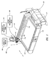
- FIG. 1 shows an abrasive jet assembly 100 for processing a wide range of workpieces.
- the abrasive jet system 100 includes an end effector assembly 114 moved using an actuation system 115.
- a control system 117 commands the actuation system 115 to control the path of travel of the end effector assembly 114, capable of generating and delivering a downwardly directed fluid jet (e.g., a waterjet, abrasive jet, and the like) suitable for cleaning, abrading, cutting, milling, or otherwise processing workpieces.
- a downwardly directed fluid jet e.g., a waterjet, abrasive jet, and the like
- the actuation system 115 of Figure 1 includes a ram 116 for motion along a vertical Z-axis.
- the ram 116 is slidably coupled to a bridge 110 for motion along an X-axis that is generally parallel to a longitudinal axis 119 (shown corresponding to the X-axis) of the bridge 110.
- the bridge 110 is mounted on one or more rails 123 to allow the bridge 110 to move in a direction perpendicular to its longitudinal axis 119.
- the illustrated bridge 110 can move along a Y-axis that is generally perpendicular to the X-axis.
- the end effector assembly 114 can be moved along the X-axis, Y-axis, and/or Z-axis using the actuation system 115.
- the control system 117 may generally include one or more computing devices, such as controllers, processors, microprocessors, digital signal processors (DSP), application-specific integrated circuits (ASIC), and the like. To store information, the control system 117 may also include one or more storage devices, such as volatile memory, non-volatile memory, read-only memory (ROM), random access memory (RAM), and the like. The storage devices can be coupled to the computing devices by one or more busses.
- the control system 117 of Figure 1 may further include one or more input devices (e.g., a display, keyboard, touchpad, controller module, or any other peripheral device for user input).
- the end effector assembly 114 is coupled to a source of pressurized fluid 155, a source of abrasive 156, and a venting pressurization device 158.
- Pressurized fluid such as water
- abrasive from the source of pressurized fluid 155 and abrasive from the source of abrasive 156 are combined together in the end effector assembly 114 to generate an abrasive jet comprising both abrasive (or other media) and the fluid.
- the venting pressurization device 158 can actively vent the end effector assembly 114 by providing a venting fluid (e.g., air) to control the flow of abrasive within the end effector assembly 114 to, for example, improve performance, increase the working life of one or more components of the end effector assembly 114, adjust entrainment of the abrasive, and the like.
- a venting fluid e.g., air
- the source of abrasive 156 can contain various types of abrasive that are ultimately entrained in the fluid jet. Although many different types of abrasive may be used, some embodiments use particles on the order of about 220 mesh or finer. The particular size can be selected based on the rate of abrasion and the desired surface textures (e.g., surface smoothness). Exemplary abrasive includes garnet particles, silica sand, glass particles, combinations thereof, and the like. The characteristics of abrasive can be selected based on whether the fluid jet abrades, texturizes, cuts, etches, polishes, cleans, or performs another procedure. Other types of media, even non-abrasive media, can also be contained in and outputted by the source 156, if needed or desired.
- the venting pressurization device 158 of Figure 1 may be a gas (e.g., air, nitrogen, and the like) compressor, such as a pump with a fixed or variable displacement, that causes the pressure of the gas delivered to the end effector assembly 114 to be greater than the ambient air pressure and/or the temperature of the gas to be greater than the ambient temperature.
- the venting pressurization device 158 is an electric pump capable of compressing a gas to a pressure of at least (0.34 MPa) (50 psi).
- the venting pressurization device 158 may be a fan or blower driven by one or more motors.
- the venting pressurization device 158 includes a vacuum device for drawing a vacuum such that a pressure within a portion of the end effector assembly 114 is less than the ambient air pressure.
- the abrasive jet is discharged from the end effector assembly 114 towards a workpiece positioned on a table/catcher tank 170 and is manipulated along a selected path, using selected operating parameters, to process the workpiece to achieve a desired end product.
- the control system 117 may be used to control the source of pressurized fluid 155, the source of abrasive 156, and/or the venting pressurization device 158 to produce types of abrasive jets with desired characteristics.
- the end effector assembly 114 includes a valve assembly 214 and a nozzle assembly 200.
- the end effector assembly 114 may also include an annular shield or skirt 212 that is temporarily or permanently coupled to the nozzle assembly 200.
- the nozzle assembly 200 can be for ultrahigh pressures, medium pressures, low pressures, or combinations thereof.
- Ultrahigh pressure cutting head assemblies can operate at pressures equal to or greater than about 551 MPa (80,000 psi).
- High-pressure cutting head assemblies can operate at a pressure in the range of about 345 MPa (50,000 psi) to about 621 MPa (90,000 psi).
- Medium-pressure cutting head assemblies can operate at a pressure in the range of about 103 MPa (15,000 psi) to about 345 MPa (50,000 psi).
- Low-pressure cutting head assemblies can operate at a pressure in the range of about 69 MPa (10,000 psi) to about 276 MPa (40,000 psi).
- the components of cutting head assemblies can be selected based on the operating parameters, such as working pressures, cutting action, and the like.
- the valve assembly 214 selectively controls the flow of pressurized fluid into the nozzle assembly 200.
- U.S. Publication No. 2003/0037650 discloses various types of valve assemblies that can be used with the illustrated nozzle assembly 200.
- valve assemblies can also be used with the nozzle assembly 200, if needed or desired.
- Pressurized fluid from the source of fluid 155 can pass downwardly through the valve assembly 214 and into the nozzle assembly 200.
- abrasives from the abrasive source 156 are delivered into the nozzle assembly 200 via an abrasive port 222.
- the illustrated nozzle assembly 200 also includes an auxiliary port 220 used to control operation of the end effector assembly 114.
- the port 220 can allow the introduction of a second substance or allow the nozzle assembly 200 to be connected to a pressurization source (e.g., a vacuum source, pump, and the like) or one or more sensors (e.g., pressure sensors).
- a pressurization source e.g., a vacuum source, pump, and the like
- sensors e.g., pressure sensors
- a venting line 232 provides communication between the nozzle assembly 200 and the venting pressurization device 158.
- a venting fluid from the venting pressurization device 158 may pass through the venting line 232 and into the nozzle assembly 200.
- the venting line 232 in some embodiments, is in the form of one or more hoses, conduits, tubes, pipes, or other suitable components that can define fluid pathways.
- the venting line 232 is a flexible hose extending between the nozzle assembly 200 and the venting pressurization device158.
- a protruding line connector 234 of the nozzle assembly 200 is coupled to a downstream end 235 of the venting line 232.
- the pressurization device 158 can be coupled directly to the exterior of the nozzle assembly 200.
- the pressurization device 158 can be physically mounted to the nozzle assembly 200 by a plurality of fasteners, welds, or the like.
- Various types of connectors or brackets can be used to couple the pressurization device 158 to the nozzle assembly 200.
- the nozzle assembly 200 can thus carry the pressurization device 158 during processing.
- FIG 3 illustrates a venting system 239 including the venting pressurization device 158, the venting line 232, and a vented cutting head body 227 of the nozzle assembly 200.
- the nozzle assembly 200 includes a feed conduit 218, the cutting head body 227, and a mixing tube 225 releasably coupled to the cutting head body 227 via a retainer 229 ( Figure 4 ).
- the mixing tube 225 extends along the length of the shield 212.
- a jet generating assembly 236 of Figure 4 for generating a fluid jet includes an orifice mount 260 and a jewel orifice 241 and, in some embodiments, a seal assembly 238.
- the illustrated jet generating assembly 236 produces a high-pressure fluid jet from the feed fluid F flowing through the feed conduit 218.
- the seal assembly 238 has a passageway 246 that tapers inwardly in the downstream direction so as to direct the fluid F into and through the jewel orifice 241.
- the jewel orifice 241 produces a fluid jet in which abrasive A, flowing through the abrasive port 222, is entrained at a mixing region 249, illustrated as a mixing chamber.
- abrasive A flowing through the abrasive port 222
- a mixing region 249 illustrated as a mixing chamber.
- Various types of jewel orifices or other fluid jet producing devices can be used to achieve the desired flow characteristics of a fluid jet.
- the orifice mount 260 is fixed with respect to the cutting head body 227 and includes a recess (e.g., a disk-shaped recess) dimensioned to receive and to hold the jewel orifice 241.
- the jewel orifice 241 is kept in proper alignment with respect to the passageway 246 of the seal assembly 238 and the mixing tube 225.
- the configuration and size of the orifice mount 260 can be selected based on the desired position of the jewel orifice 241.
- the illustrated orifice mount 260 is disk-shaped and is removably retained by the cutting head body 227. If the orifice mount 260 becomes worn, it can be replaced without damaging the cutting head body 227 or altering the venting functionality of the cutting head body 227.
- a vent 239 includes a venting port 243 positioned between the orifice mount 260 and the mixing region 249.
- the venting port 243 can be in the form of one or more apertures, openings, inlets, and the like. Fluid from the venting line 232 can flow through the venting port 243 into or out of a venting region 245, illustrated as a venting chamber, to control movement of the abrasive A within the cutting head body 227.
- the pressure in the venting chamber 245 can be sufficiently high to minimize, limit, or substantially prevent the movement of the abrasive A through the venting chamber 245.
- a wide range of desired pressure differentials can be maintained between the mixing region 249 and the venting chamber 245 using the vent 239, as detailed below.
- the venting port 243 has a diameter that is equal to or less than about 0.762 mm (0.03 inches), about 0.508 mm (0.02 inches), or about 0.254 mm (0.01 inches), or ranges encompassing such dimensions.
- the venting port 243 having a diameter equal to or less than about 0.508 mm (0.03 inches) can be used to deliver air at a pressure in the range of about 0 MPa (0 psi) to about 0.2 MPa (30 psi) such that the pressurized venting chamber 245 serves as an effective abrasive barrier without appreciably effecting the vacuum in the mixing region 249.
- venting port 243 can be selected to maintain a vacuum (or desired positive pressure) in the mixing region 249 for proper abrasive entrainment. Different working pressures in the mixing region 249 can be utilized to adjust performance of the waterjet assembly 100 as discussed in detail below.
- the cutting head body 227 has a one-piece construction formed via a machining process, injection molding process (e.g., an injection molding process), and the like.
- the cutting head body 227 can be made, in whole or in part, of one or more metals (e.g., steel, aluminum, titanium, etc.), metal alloys, and the like. Because the cutting head body 227 has a reliable one-piece construction, it is not prone to malfunction. Therefore, even though other components of the nozzle assembly 200 may be frequently replaced, the cutting head body 227 has a relatively long working life with consistent, reliable operation.
- the cutting head body 227 of Figure 5 includes a sidewall 261 that defines an orifice mount receiving section 262, the venting chamber 245, the mixing region 249, and the bore 248 for receiving the mixing tube 225.
- Figure 5 shows the cutting head body 227 with the mixing tube 225 removed.
- the receiving section 262 is adapted to receive and support the orifice mount 260.
- the venting port 243 is spaced apart from a lower surface 269 of the orifice mount 260 (shown separated from the cutting head body 227).
- the lower surface 269 of the orifice mount 260 can bear against the support surface 267 of the cutting head body 227.
- the receiving section 262 includes a generally cylindrical sidewall 263 extending from the support surface 267.
- the sidewall 263 can closely surround the orifice mount 260 to limit side-to-side movement of the jewel orifice 241.
- a seating member 273 can facilitate seating of the orifice mount 260.
- the seating member 273 can be an annular member, an O-ring, or other type of component suitable for maintaining the proper position of the orifice mount 260 with respect to the receiving section 262.
- a removable isolator 283 is positioned between the venting chamber 245 and the mixing region 249.
- the isolator 283 of Figure 6 is a convergent-divergent flow device that includes an upstream converging section 297 and a downstream diverging section 299.
- the isolator 283 has a through-hole 285 sized to closely surround the fluid jet passing therethrough so as to physically obstruct or impede the flow of abrasive in the upstream direction.
- the isolator 283 can thus inhibit upstream flow of the abrasive A, if any, into the venting chamber 245 while the through-hole 285 allows a desired amount of spreading of the fluid jet before the abrasive entrainment.
- the isolator can create an accelerated flow around the fluid jet.
- the isolator 283 can create a high speed flow (e.g. , a supersonic flow) about the fluid jet. This flow can further prevent upstream migration of the abrasive.
- the isolator 283 can be removably coupled to the cutting head body 227. External threads of the isolator 283 can mate with internal threads of the cutting head body 227. The isolator 283 can be rotated to remove it from the cutting head body 227. In other embodiments, the isolator 283 is permanently coupled to the cutting head body 227 via one or more welds. In other embodiments, the isolator 283 can be integrally formed with the cutting head body 227.
- the isolator 283 can be made, in whole or in part, of a hardened, wear-resistant material. This type of material is especially well suited for reducing wear to increase the service life of the isolator 283.
- the isolator 283 can be repeatedly exposed to the fluid jet exiting the orifice mount 260.
- the hardened, wear-resistant material may be harder than the material forming the cutting head body 227. Accordingly, the isolator 283, for example, can erode less than the cutting head body 227 when both the isolator 283 and the cutting head body 227 are contacted by the fluid jet.
- Hardened, wear-resistant materials may include, without limitation, tungsten carbide, titanium carbide, alumina, and other abrasion resistant materials that can withstand exposure to the fluid jets disclosed herein.
- Various types of testing methods e.g ., the Rockwell hardness test or Brinell hardness test
- Rockwell hardness test or Brinell hardness test
- an inner surface 287 of the cutting head body 227 defines the mixing region 249, an abrasive inlet 291 of the abrasive port 222, and an auxiliary inlet 293 of the auxiliary port 220.
- Abrasive passing through the inlet 291 is entrained in the fluid jet passing through the mixing region 249.
- Entraining can include, without limitation, mixing, combining, or otherwise bringing together two or more different substances.
- the abrasives A can be partially or fully mixed with the fluid forming the fluid jet such that the fluid jet carries the abrasives A into and through the mixing tube 225, thereby forming an abrasive jet.
- the term "abrasive jet” generally refers to, but is not limited to, a fluid jet carrying abrasive.
- the bore 248 of Figure 5 includes an entrance 250 positioned opposite the isolator 283, an exit 252 opposite the entrance 250, and a longitudinal axis 254 extending therebetween.
- the entrance 250 is proximate to the location of abrasive entrainment to facilitate entry of the abrasive jet into the mixing tube 225.
- a sensor 302 can be operated to evaluate performance of the nozzle assembly 200.
- the sensor 302 can be a pressure sensor capable of outputting at least one signal indicative of the pressure in a passageway 304 extending between the receiving section 263 and the mixing tube 225.
- the sensor 302 of Figure 6 is positioned in or connected to the venting chamber 245 and measures the pressure proximate to a fluid jet flow path 328 along the passageway 304. As the fluid jet passes along the flow path 328, the sensor 302 can continuously or intermittently measure the pressure in the venting chamber 245. Sensors can also be at any number of other locations along the cutting head body 227.
- the term "pressure sensor” includes, but is not limited to, a sensor that detects an absolute pressure or a pressure differential, or both.
- Exemplary pressure sensors include, without limitation, absolute pressure sensors, differential pressure sensors, gauge pressure sensors, pressure transducers, and the like.
- the illustrated sensor 302 is a pressure sensor capable of sending one or more signals to the control system 117 (illustrated schematically in Figure 6 ) via a line 311 (shown in phantom line). In other systems, the sensor 302 communicates wirelessly with the control system 117.
- the control system 117 can adjust one or more processing parameters (e.g. , operating pressures, flow rates of the working fluid or abrasive, flow rate of a venting fluid, and the like). For example, if the pressure in the venting chamber 245 is below a desired pressure, the control system 117 commands the venting pressurization device 158 to increase the pressure in the venting chamber 245. The control system 117 can also shut off the jet, for example, during non-processing stages ( e.g ., between processing workpieces), to perform maintenance, to replace components of the abrasive jet system 100, and the like.
- processing parameters e.g. , operating pressures, flow rates of the working fluid or abrasive, flow rate of a venting fluid, and the like.
- the cutting head body 227 includes the sidewall 261 defining a venting through-hole 312 extending outwardly from the venting port 243, which is positioned upstream of an isolator 313 with a through-hole 317 having, in one embodiment, a generally uniform diameter along the longitudinal length of through-hole 317.
- a tubular surface 314 of the cutting head body 227 defines the venting through-hole 312 and extends continuously and uninterruptedly from the venting port 243 to an exterior surface 322 of the cutting head body 227.
- the illustrated venting through-hole 312 has a generally straight configuration. In other embodiments, the venting through-hole 312 can have a curved configuration or angled configuration.
- fluid F from the source of pressurized fluid 155 is delivered through the valve assembly 214 along the feed conduit 218 of the nozzle assembly 200 of Figure 4 .
- the fluid F is then delivered to the jet generating assembly 236.
- the jewel orifice 241 produces a fluid jet that passes through a central passageway 316 of the orifice mount 260 (see Figure 5 ).
- the fluid jet exits a fluid jet exit 318 of the orifice mount 260, enters the venting chamber 245, and proceeds through the isolator 283 into the mixing region 249.
- the abrasive A from the source of abrasive 156 is delivered through the abrasive port 222 and into the mixing region 249 via the abrasive inlet 291.
- the fluid jet and abrasive A are combined together and delivered through a channel 234 of the mixing tube 225 of Figure 4 .
- the abrasive A and fluid F can be further mixed in the mixing tube 225 to produce a desired abrasive jet 240 exiting the mixing tube 225.
- the venting pressurization device 158 outputs venting fluid that passes through the venting port 243 and into the venting chamber 245.
- the venting pressurization device 158 can keep the venting chamber 245 at a desired pressure (e.g., below atmospheric pressure, equal to atmospheric pressure, above atmospheric pressure, or combinations thereof).
- the pressure in the venting chamber 245 can be selected based on the desired pressure differential between the venting chamber 245 and the mixing region 249.
- the pressure of the venting chamber 245 can be below atmospheric pressure to increase spreading of the jet.
- the pressure of the venting chamber 245 can be generally at atmospheric pressure to avoid pressure changes due to improper operation of pressurization devices, such as mechanical pumps.
- ambient air can flow through the cutting head body 227 and into the venting chamber 245 to keep the venting chamber 245 at approximately atmospheric pressure.
- the pressure of the venting chamber 245 can be greater than atmospheric pressure to enhance jet coherency.
- the pressure of the venting chamber 245 may be at different pressures based on the desired properties of the jet.
- the sensor 302 of Figure 7 positioned along the venting line 232 is used to evaluate the venting pressures, if needed or desired. As such, the pressure of the venting chamber 245 can be accurately controlled to achieve a constant or varying pressure.
- the flow rate of the venting fluid can be increased or decreased to increase or decrease the pressure in the venting chamber 245.
- a sufficient amount of venting fluid can be passed through the venting port 243 to keep the venting chamber pressure at or above the pressure in the mixing region 249.
- the venting chamber 245 can be maintained at or above a first pressure
- the mixing region 249 can be maintained at or below a second pressure, which is less than the first pressure.
- a vacuum is maintained in the mixing region 249.
- the first pressure can be at least 0.3 MPa (0.05 psi) greater than the second pressure. This pressure differential may be maintained to inhibit, limit, or substantially prevent the abrasives A from migrating into and/or through the venting chamber 245.
- the venting fluid and the fluid jet can flow through the isolator 283 and into the mixing region 249, thereby further inhibiting upstream flow of the abrasive A.
- Vents can also provide passive venting by, for example, establishing fluid communication between the ambient external air and the interior of a cutting head body.
- Figure 8A shows a cutting head body 400 that includes a passive vent 401 having a venting through-hole 402 with a first end 410 for communicating with a venting chamber 416 and a second end 420 for communicating with external ambient air.
- the pressure in the cutting head body 400 can be at a relatively low pressure (e.g., below atmospheric pressure) due to the vacuum effect of the high speed flow of the fluid jet.
- the low pressure causes ambient air to be drawn through the second end 420 and into the vent through-hole 402.
- the air is then drawn into the venting chamber 416, resulting in a relatively high venting chamber pressure as compared to the pressure in a mixing region 430.
- the passive vent 401 can include one or more orifice members to control the flow of fluid into the venting chamber 416.
- a flow regulating orifice member 423 is positioned along the passive vent 401 and has a through-hole 427 through which ambient air flows.
- the diameter of the through-hole 427 can be increased or decreased to increase or decrease the flow rate of air passing through the orifice member 423 and ultimately into the venting chamber 416.
- the through-hole 427 can have a generally uniform diameter, illustrated in Figure 8B , or a varying diameter along its longitudinal length.
- the orifice 423 can be permanently or temporarily coupled to the cutting head body 400.
- the orifice member 423 has an outer surface 431 with external threads that mate with internal threads along an inner surface 429 of the passive vent 401.
- the orifice member 423 is permanently coupled to the inner surface 429 via one or more adhesives or welds.
- the illustrated cutting head body 400 includes a stop 433 that prevents movement of the orifice member 423 towards the venting chamber 416.
- the orifice member 423 can be replaced with another orifice member based on the waterjet orifice size.
- Example orifice members include, without limitation, metering orifices, regulating orifices, and the like. Regulating orifices can be in the form of valves for actively adjusting fluid flow rates.
- the illustrated orifice member 423 is a type of orifice without movable components for producing desired fluid flow rates.
- the orifice member 423 can be made, in whole or in part, of a hardened material, such as a wear resistant material, to resist wear that may lead to appreciable dimensional changes. If a highly-pressurized fluid flows through the passive vent 401, the orifice member 423 can be in the form of a jewel. Other types of materials can also be used to make the orifice.
- a cutting head body can include a plurality of vents.
- An illustrated cutting head body 462 of Figure 9 includes a plurality of vents 470, 472, 474.
- the vents 470, 472, 474 can be used with a venting pressurization device, such as the venting pressurization device 158 discussed in connection with Figure 1 , or with atmospheric air, as discussed in connection with Figure 8A .
- the vent 470 may provide communication between a venting chamber 480 and the external environment, while the vent 472 may provide communication between a venting pressurization device and the venting chamber 480.
- the illustrated venting chamber 480 is a generally cylindrical passageway extending between an orifice mount receiving section 482 and a mixing region 486.
- An isolator can be positioned between the venting chamber 480 and the mixing region 486 to further inhibit upstream movement of the abrasives in the mixing region 486, if needed or desired.
- the vents of Figures 2-8B can be formed by drilling a hole through the cutting head body.
- the vent can be formed during the manufacturing of the cutting head body.
- a cutting head body with a vent can be formed using an injection molding process.
- a single manufacturing process can form a unitary vented cutting head body.
- the cutting head body can have a multi-piece construction.
- Figure 10 illustrates a cutting head body 500 that includes an upstream section 502 and a downstream section 504. Vents 510 are formed in the upstream section 502, the downstream section 504, or both.
- vent 510 is formed by the upstream section 502 and the downstream section 504.
- the vent 510 extends radially outward from a center bore 519 of the cutting head body 500 and is formed, at least in part, by the downstream section 504.
- vent 510 can be formed, at least in part, by a groove 511 (see Figure 11 ) extending generally along an upper surface 513 of the downstream section 504 and a lower surface 515 of the upstream section 502.
- the groove 511 can have a U-shaped cross-section, V-shaped cross-section, semi-circular cross-section, or any other suitable shape.
- Various types of milling or other machining techniques can be used to form the groove 511.
- the upstream section 502 can be conveniently separated from the downstream section 504. If an orifice member is positioned along the vent 510, the vent 510 can be accessed to inspect, replace, and/or reposition the orifice member. Any number of radially extending grooves can be provided to achieve the desired venting. Figure 11 shows an additional groove 519 in a broken line.
- the upstream and downstream sections 502, 504 can be permanently coupled together via one or more welds or permanent fasteners. Alternatively, the upstream and downstream sections 502, 504 can be removably coupled together via one or more couplers, fasteners (e.g., bolts), and the like.
Landscapes
- Engineering & Computer Science (AREA)
- Mechanical Engineering (AREA)
- Perforating, Stamping-Out Or Severing By Means Other Than Cutting (AREA)
Description
- The present invention relates generally to abrasive jet systems and, in particular, to abrasive jet systems having a vented cutting head body.
- Conventional abrasive jet systems are used to process workpieces by pressurizing fluid and then delivering the pressurized fluid against a workpiece. Abrasive jet systems produce high-pressure abrasive fluid jets (commonly referred to as abrasive jets) suitable for cutting through hard materials. High-pressure fluid can flow through a jet-forming jewel orifice of a cutting head assembly to form a high-pressure fluid jet into which abrasive particles are entrained. The high-pressure abrasive fluid jet is discharged from the cutting head assembly towards the workpiece.
- The abrasive and the fluid jet are often mixed together in a mixing chamber within the cutting head assembly. Abrasive delivered into the mixing chamber has a tendency to move upstream through the cutting head assembly towards the jewel orifice. This is because the upstream pressure (e.g., the pressure in a flow passageway between the mixing chamber and the jewel orifice) may be lower than the pressure in the mixing chamber. The pressure differential often leads to abrasive movement that may result in the abrasive striking and causing damage to a jewel orifice holder supporting the jewel orifice.
- The abrasive may also eventually migrate upstream past the jewel orifice holder and ultimately to the top of the jewel orifice. Abrasive may slowly accumulate on the upstream surfaces of the jewel orifice. If some of the accumulated abrasive becomes dislodged, it may be picked-up by the high-pressure fluid that is forced through the jet-forming jewel orifice. The picked-up abrasive may quickly damage the jewel orifice, resulting in malfunctioning and/or significantly impaired performance of the cutting head assembly. The abrasive jet system has to be shut down to replace the damaged jewel orifice and clean abrasive from the cutting head assembly such that the waterjet cutting process can be performed once again. Unfortunately, the downtime may significantly reduce the productivity of the abrasive jet system.
- Related prior art is disclosed in
US 2005/017091 ,WO 92/19384 US 4 951 429 ,US 4 995 164 ,EP 1 422 026 , which is seen as closest prior art, andUS 5 320 289 . - Document
EP 1 422 026 discloses in itsFigure 2 an abrasive jet system having a nozzle assembly for producing an abrasive jet, the abrasive jet system comprising: - a cutting head body of the nozzle assembly including an orifice mount receiving section adapted to receive an orifice mount, a mixing region positioned downstream of the orifice mount receiving section, an abrasive feed port through which abrasive moves into the mixing region, and a cutting head vent having a venting port and a venting through-hole extending outwardly from the venting port through a sidewall, the venting port positioned between the orifice mount receiving section and the mixing region.
- An abrasive jet system, in some embodiments, has a nozzle assembly and a venting system for controlling the flow of media, such as abrasive, within the nozzle assembly. The venting system can protect various components of the nozzle system from the abrasive.
- The venting system may include one or more vents for regulating the pressure within a cutting head body of the nozzle assembly to minimize, limit, or substantially eliminate media that reaches components of the nozzle assembly, such as an orifice mount, jewel orifice, and the like. The vents, in some embodiments, may include at least one venting port positioned between an orifice mount that retains a jewel orifice and a mixing region in which abrasive is mixed with a fluid jet produced by the jewel orifice. An isolator between the mixing region and orifice mount further protects the jewel orifice or other upstream components.
- In some systems, an abrasive jet system having a nozzle assembly for producing an abrasive jet comprises a cutting head body that includes an orifice mount receiving section adapted to receive an orifice mount for retaining a jewel orifice, a mixing region positioned downstream of the orifice mount receiving section, an abrasive feed port through which abrasive moves into the mixing region, and a cutting head vent. The cutting head vent has a venting port and a venting through-hole extending outwardly from the venting port through a sidewall of the cutting head body. The venting port is positioned between the orifice mount receiving section and the mixing region such that the venting port is downstream of a fluid jet exit of an orifice mount in the orifice mount receiving section during use.
- In some systems, an abrasive waterjet cutting head body comprises a mixing region, an abrasive feed port through which abrasive moves into the mixing region, a venting port positioned upstream of the abrasive feed port and downstream of an orifice mount seating face of the cutting head body such that the venting port is downstream of a fluid jet exit of an orifice mount seated against the orifice mount seating face. In some embodiments, a venting passageway extends from the venting port through a sidewall of the cutting head body.
- In some systems, a method for producing an abrasive waterjet is provided. The method includes delivering a fluid jet produced by a jet generating orifice through an orifice mount towards a mixing region in the cutting head body. The abrasive is delivered through an abrasive feed port to the mixing region to entrain the abrasive in the fluid jet. The fluid is passed through a venting port positioned upstream of the mixing region and downstream of the orifice mount to adjust pressure in at least a portion of a passageway in the cutting head body extending between the orifice mount and the mixing region.
-
-
Figure 1 is an isometric view of an abrasive jet system. -
Figure 2 is an isometric view of an end effector assembly. -
Figure 3 is a side elevational view of a nozzle assembly in communication with a venting pressurization device. -
Figure 4 is a cross-sectional view of a nozzle assembly having a vented cutting head body. -
Figure 5 is an exploded, cross-sectional view of some components of a nozzle assembly. -
Figure 6 is a detailed cross-sectional view of a portion of a cutting head body having a vent and a removable isolator. -
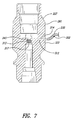
Figure 7 is a cross-sectional view of a vented cutting head body taken along line 7-7 ofFigure 4 . -
Figure 8A is a cross-sectional view of a vented cutting head body for venting ambient air. -
Figure 8B is a detailed view of a portion of the cutting head body ofFigure 8A . -
Figure 9 is a cross-sectional view of a vented cutting head body including a plurality of vents. -
Figure 10 is a cross-sectional view of a multi-piece cutting head body. -
Figure 11 is a cross-sectional view of the cutting head body ofFigure 10 taken along line 11-11. - The following description relates to abrasive jet systems, assemblies, and subcomponents, for generating and delivering abrasive jets suitable for cleaning, abrading, cutting, milling, or otherwise processing workpieces. An abrasive jet system can have a nozzle assembly and a venting system for controlling the flow of abrasive within the nozzle assembly. The venting system can include one or more vents for regulating the pressure within at least a portion of the nozzle assembly to minimize, limit, or substantially eliminate physical interaction between the abrasive and an upstream component. The vents can be positioned between an orifice mount retaining a jewel orifice and an internal mixing region in which abrasive is mixed with a fluid jet. The vents, in some embodiments, can be used to increase or decrease the pressure upstream of a mixing region to protect a wide range of different components that are upstream of the mixing region.
-
Figure 1 shows anabrasive jet assembly 100 for processing a wide range of workpieces. Theabrasive jet system 100 includes anend effector assembly 114 moved using anactuation system 115. Acontrol system 117 commands theactuation system 115 to control the path of travel of theend effector assembly 114, capable of generating and delivering a downwardly directed fluid jet (e.g., a waterjet, abrasive jet, and the like) suitable for cleaning, abrading, cutting, milling, or otherwise processing workpieces. - The
actuation system 115 ofFigure 1 includes aram 116 for motion along a vertical Z-axis. Theram 116 is slidably coupled to abridge 110 for motion along an X-axis that is generally parallel to a longitudinal axis 119 (shown corresponding to the X-axis) of thebridge 110. Thebridge 110 is mounted on one ormore rails 123 to allow thebridge 110 to move in a direction perpendicular to itslongitudinal axis 119. The illustratedbridge 110 can move along a Y-axis that is generally perpendicular to the X-axis. Theend effector assembly 114 can be moved along the X-axis, Y-axis, and/or Z-axis using theactuation system 115. - Other types of positioning systems employing one or more linear slides, rail systems, carriages, motors, and the like can be used to selectively move the
end effector assembly 114 as needed or desired.U.S. Patent No. 6,000,308 andU.S. Publication No. 2003/0037650 (Application Serial No.09/940,689 end effector assembly 114. - The
control system 117 may generally include one or more computing devices, such as controllers, processors, microprocessors, digital signal processors (DSP), application-specific integrated circuits (ASIC), and the like. To store information, thecontrol system 117 may also include one or more storage devices, such as volatile memory, non-volatile memory, read-only memory (ROM), random access memory (RAM), and the like. The storage devices can be coupled to the computing devices by one or more busses. Thecontrol system 117 ofFigure 1 may further include one or more input devices (e.g., a display, keyboard, touchpad, controller module, or any other peripheral device for user input). - The
end effector assembly 114 is coupled to a source ofpressurized fluid 155, a source of abrasive 156, and a ventingpressurization device 158. Pressurized fluid, such as water, from the source ofpressurized fluid 155 and abrasive from the source of abrasive 156 are combined together in theend effector assembly 114 to generate an abrasive jet comprising both abrasive (or other media) and the fluid. The ventingpressurization device 158 can actively vent theend effector assembly 114 by providing a venting fluid (e.g., air) to control the flow of abrasive within theend effector assembly 114 to, for example, improve performance, increase the working life of one or more components of theend effector assembly 114, adjust entrainment of the abrasive, and the like. - The source of abrasive 156 can contain various types of abrasive that are ultimately entrained in the fluid jet. Although many different types of abrasive may be used, some embodiments use particles on the order of about 220 mesh or finer. The particular size can be selected based on the rate of abrasion and the desired surface textures (e.g., surface smoothness). Exemplary abrasive includes garnet particles, silica sand, glass particles, combinations thereof, and the like. The characteristics of abrasive can be selected based on whether the fluid jet abrades, texturizes, cuts, etches, polishes, cleans, or performs another procedure. Other types of media, even non-abrasive media, can also be contained in and outputted by the
source 156, if needed or desired. - The venting
pressurization device 158 ofFigure 1 may be a gas (e.g., air, nitrogen, and the like) compressor, such as a pump with a fixed or variable displacement, that causes the pressure of the gas delivered to theend effector assembly 114 to be greater than the ambient air pressure and/or the temperature of the gas to be greater than the ambient temperature. In some embodiments, the ventingpressurization device 158 is an electric pump capable of compressing a gas to a pressure of at least (0.34 MPa) (50 psi). Alternatively, the ventingpressurization device 158 may be a fan or blower driven by one or more motors. In some embodiments, the ventingpressurization device 158 includes a vacuum device for drawing a vacuum such that a pressure within a portion of theend effector assembly 114 is less than the ambient air pressure. - The abrasive jet is discharged from the
end effector assembly 114 towards a workpiece positioned on a table/catcher tank 170 and is manipulated along a selected path, using selected operating parameters, to process the workpiece to achieve a desired end product. Thecontrol system 117 may be used to control the source ofpressurized fluid 155, the source of abrasive 156, and/or the ventingpressurization device 158 to produce types of abrasive jets with desired characteristics. - Referring to
Figure 2 , theend effector assembly 114 includes avalve assembly 214 and anozzle assembly 200. In some embodiments, if desired, theend effector assembly 114 may also include an annular shield orskirt 212 that is temporarily or permanently coupled to thenozzle assembly 200. Thenozzle assembly 200 can be for ultrahigh pressures, medium pressures, low pressures, or combinations thereof. Ultrahigh pressure cutting head assemblies can operate at pressures equal to or greater than about 551 MPa (80,000 psi). High-pressure cutting head assemblies can operate at a pressure in the range of about 345 MPa (50,000 psi) to about 621 MPa (90,000 psi). Medium-pressure cutting head assemblies can operate at a pressure in the range of about 103 MPa (15,000 psi) to about 345 MPa (50,000 psi). Low-pressure cutting head assemblies can operate at a pressure in the range of about 69 MPa (10,000 psi) to about 276 MPa (40,000 psi). - The components of cutting head assemblies, such as mixing tubes, jewel orifices, and orifice mounts can be selected based on the operating parameters, such as working pressures, cutting action, and the like. The
valve assembly 214 selectively controls the flow of pressurized fluid into thenozzle assembly 200.U.S. Publication No. 2003/0037650 discloses various types of valve assemblies that can be used with the illustratednozzle assembly 200. - Other types of valve assemblies can also be used with the
nozzle assembly 200, if needed or desired. - Pressurized fluid from the source of
fluid 155 can pass downwardly through thevalve assembly 214 and into thenozzle assembly 200. Within thenozzle assembly 200, abrasives from theabrasive source 156 are delivered into thenozzle assembly 200 via anabrasive port 222. The illustratednozzle assembly 200 also includes anauxiliary port 220 used to control operation of theend effector assembly 114. Theport 220, for example, can allow the introduction of a second substance or allow thenozzle assembly 200 to be connected to a pressurization source (e.g., a vacuum source, pump, and the like) or one or more sensors (e.g., pressure sensors).U.S. Publication No. 2003/0037650 andU.S. Patent Nos. 6,875,084 and5,643,058 disclose methods and devices that can be used with theports 220, 223. - A
venting line 232 provides communication between thenozzle assembly 200 and the ventingpressurization device 158. A venting fluid from the ventingpressurization device 158 may pass through theventing line 232 and into thenozzle assembly 200. Theventing line 232, in some embodiments, is in the form of one or more hoses, conduits, tubes, pipes, or other suitable components that can define fluid pathways. In some embodiments, theventing line 232 is a flexible hose extending between thenozzle assembly 200 and the venting pressurization device158. A protrudingline connector 234 of thenozzle assembly 200 is coupled to adownstream end 235 of theventing line 232. - The
pressurization device 158 can be coupled directly to the exterior of thenozzle assembly 200. For example, thepressurization device 158 can be physically mounted to thenozzle assembly 200 by a plurality of fasteners, welds, or the like. Various types of connectors or brackets can be used to couple thepressurization device 158 to thenozzle assembly 200. Thenozzle assembly 200 can thus carry thepressurization device 158 during processing. -
Figure 3 illustrates aventing system 239 including the ventingpressurization device 158, theventing line 232, and a vented cuttinghead body 227 of thenozzle assembly 200. Thenozzle assembly 200 includes afeed conduit 218, the cuttinghead body 227, and a mixingtube 225 releasably coupled to the cuttinghead body 227 via a retainer 229 (Figure 4 ). The mixingtube 225 extends along the length of theshield 212. Ajet generating assembly 236 ofFigure 4 for generating a fluid jet includes anorifice mount 260 and ajewel orifice 241 and, in some embodiments, aseal assembly 238. The illustratedjet generating assembly 236 produces a high-pressure fluid jet from the feed fluid F flowing through thefeed conduit 218. - Sometimes the
seal assembly 238 has apassageway 246 that tapers inwardly in the downstream direction so as to direct the fluid F into and through thejewel orifice 241. Thejewel orifice 241 produces a fluid jet in which abrasive A, flowing through theabrasive port 222, is entrained at a mixingregion 249, illustrated as a mixing chamber. Various types of jewel orifices or other fluid jet producing devices can be used to achieve the desired flow characteristics of a fluid jet. - The
orifice mount 260 is fixed with respect to the cuttinghead body 227 and includes a recess (e.g., a disk-shaped recess) dimensioned to receive and to hold thejewel orifice 241. Thejewel orifice 241 is kept in proper alignment with respect to thepassageway 246 of theseal assembly 238 and the mixingtube 225. The configuration and size of theorifice mount 260 can be selected based on the desired position of thejewel orifice 241. The illustratedorifice mount 260 is disk-shaped and is removably retained by the cuttinghead body 227. If theorifice mount 260 becomes worn, it can be replaced without damaging the cuttinghead body 227 or altering the venting functionality of the cuttinghead body 227. - A
vent 239 includes a ventingport 243 positioned between theorifice mount 260 and the mixingregion 249. The ventingport 243 can be in the form of one or more apertures, openings, inlets, and the like. Fluid from theventing line 232 can flow through the ventingport 243 into or out of aventing region 245, illustrated as a venting chamber, to control movement of the abrasive A within the cuttinghead body 227. In some embodiments, the pressure in theventing chamber 245 can be sufficiently high to minimize, limit, or substantially prevent the movement of the abrasive A through the ventingchamber 245. A wide range of desired pressure differentials can be maintained between the mixingregion 249 and the ventingchamber 245 using thevent 239, as detailed below. - Sometimes the venting
port 243 has a diameter that is equal to or less than about 0.762 mm (0.03 inches), about 0.508 mm (0.02 inches), or about 0.254 mm (0.01 inches), or ranges encompassing such dimensions. In some embodiments, for example, the ventingport 243 having a diameter equal to or less than about 0.508 mm (0.03 inches) can be used to deliver air at a pressure in the range of about 0 MPa (0 psi) to about 0.2 MPa (30 psi) such that thepressurized venting chamber 245 serves as an effective abrasive barrier without appreciably effecting the vacuum in the mixingregion 249. The dimensions, position, and configuration of the ventingport 243 can be selected to maintain a vacuum (or desired positive pressure) in the mixingregion 249 for proper abrasive entrainment. Different working pressures in the mixingregion 249 can be utilized to adjust performance of thewaterjet assembly 100 as discussed in detail below. - Referring to
Figure 5 , the cuttinghead body 227 has a one-piece construction formed via a machining process, injection molding process (e.g., an injection molding process), and the like. The cuttinghead body 227 can be made, in whole or in part, of one or more metals (e.g., steel, aluminum, titanium, etc.), metal alloys, and the like. Because the cuttinghead body 227 has a reliable one-piece construction, it is not prone to malfunction. Therefore, even though other components of thenozzle assembly 200 may be frequently replaced, the cuttinghead body 227 has a relatively long working life with consistent, reliable operation. - The cutting
head body 227 ofFigure 5 includes asidewall 261 that defines an orificemount receiving section 262, the ventingchamber 245, the mixingregion 249, and thebore 248 for receiving the mixingtube 225. (Figure 5 shows the cuttinghead body 227 with the mixingtube 225 removed.) The receivingsection 262 is adapted to receive and support theorifice mount 260. When theorifice mount 260 is seated against asupport surface 267 of the receivingsection 262, the ventingport 243 is spaced apart from alower surface 269 of the orifice mount 260 (shown separated from the cutting head body 227). When assembled, thelower surface 269 of theorifice mount 260 can bear against thesupport surface 267 of the cuttinghead body 227. - The receiving
section 262 includes a generallycylindrical sidewall 263 extending from thesupport surface 267. Thesidewall 263 can closely surround theorifice mount 260 to limit side-to-side movement of thejewel orifice 241. A seatingmember 273 can facilitate seating of theorifice mount 260. The seatingmember 273 can be an annular member, an O-ring, or other type of component suitable for maintaining the proper position of theorifice mount 260 with respect to the receivingsection 262. - Referring to
Figure 5 , aremovable isolator 283 is positioned between the ventingchamber 245 and the mixingregion 249. Theisolator 283 ofFigure 6 is a convergent-divergent flow device that includes an upstream convergingsection 297 and a downstream divergingsection 299. In some embodiments, including the illustrated embodiment ofFigure 6 , theisolator 283 has a through-hole 285 sized to closely surround the fluid jet passing therethrough so as to physically obstruct or impede the flow of abrasive in the upstream direction. Theisolator 283 can thus inhibit upstream flow of the abrasive A, if any, into the ventingchamber 245 while the through-hole 285 allows a desired amount of spreading of the fluid jet before the abrasive entrainment. In some embodiments, the isolator can create an accelerated flow around the fluid jet. For example, theisolator 283 can create a high speed flow (e.g., a supersonic flow) about the fluid jet. This flow can further prevent upstream migration of the abrasive. - The
isolator 283 can be removably coupled to the cuttinghead body 227. External threads of theisolator 283 can mate with internal threads of the cuttinghead body 227. Theisolator 283 can be rotated to remove it from the cuttinghead body 227. In other embodiments, theisolator 283 is permanently coupled to the cuttinghead body 227 via one or more welds. In other embodiments, theisolator 283 can be integrally formed with the cuttinghead body 227. - Various materials can be used to form the
isolator 283. In some embodiments, for example, theisolator 283 can be made, in whole or in part, of a hardened, wear-resistant material. This type of material is especially well suited for reducing wear to increase the service life of theisolator 283. In such embodiments, theisolator 283 can be repeatedly exposed to the fluid jet exiting theorifice mount 260. The hardened, wear-resistant material may be harder than the material forming the cuttinghead body 227. Accordingly, theisolator 283, for example, can erode less than the cuttinghead body 227 when both theisolator 283 and the cuttinghead body 227 are contacted by the fluid jet. - Hardened, wear-resistant materials may include, without limitation, tungsten carbide, titanium carbide, alumina, and other abrasion resistant materials that can withstand exposure to the fluid jets disclosed herein. Various types of testing methods (e.g., the Rockwell hardness test or Brinell hardness test) can be used to determine material hardness.
- Referring again to
Figures 4 and5 , aninner surface 287 of the cuttinghead body 227 defines the mixingregion 249, anabrasive inlet 291 of theabrasive port 222, and anauxiliary inlet 293 of theauxiliary port 220. Abrasive passing through theinlet 291 is entrained in the fluid jet passing through the mixingregion 249. Entraining can include, without limitation, mixing, combining, or otherwise bringing together two or more different substances. For example, the abrasives A can be partially or fully mixed with the fluid forming the fluid jet such that the fluid jet carries the abrasives A into and through the mixingtube 225, thereby forming an abrasive jet. As used herein, the term "abrasive jet" generally refers to, but is not limited to, a fluid jet carrying abrasive. - The
bore 248 ofFigure 5 includes anentrance 250 positioned opposite theisolator 283, anexit 252 opposite theentrance 250, and alongitudinal axis 254 extending therebetween. In some embodiments, theentrance 250 is proximate to the location of abrasive entrainment to facilitate entry of the abrasive jet into the mixingtube 225. - With reference to
Figure 6 , asensor 302 can be operated to evaluate performance of thenozzle assembly 200. Thesensor 302 can be a pressure sensor capable of outputting at least one signal indicative of the pressure in apassageway 304 extending between the receivingsection 263 and the mixingtube 225. Thesensor 302 ofFigure 6 is positioned in or connected to theventing chamber 245 and measures the pressure proximate to a fluidjet flow path 328 along thepassageway 304. As the fluid jet passes along theflow path 328, thesensor 302 can continuously or intermittently measure the pressure in theventing chamber 245. Sensors can also be at any number of other locations along the cuttinghead body 227. - The term "pressure sensor" includes, but is not limited to, a sensor that detects an absolute pressure or a pressure differential, or both. Exemplary pressure sensors include, without limitation, absolute pressure sensors, differential pressure sensors, gauge pressure sensors, pressure transducers, and the like. The illustrated
sensor 302 is a pressure sensor capable of sending one or more signals to the control system 117 (illustrated schematically inFigure 6 ) via a line 311 (shown in phantom line). In other systems, thesensor 302 communicates wirelessly with thecontrol system 117. - Based on one or more signals from the
sensor 302, thecontrol system 117 can adjust one or more processing parameters (e.g., operating pressures, flow rates of the working fluid or abrasive, flow rate of a venting fluid, and the like). For example, if the pressure in theventing chamber 245 is below a desired pressure, thecontrol system 117 commands the ventingpressurization device 158 to increase the pressure in theventing chamber 245. Thecontrol system 117 can also shut off the jet, for example, during non-processing stages (e.g., between processing workpieces), to perform maintenance, to replace components of theabrasive jet system 100, and the like. - Referring to
Figure 7 , the cuttinghead body 227 includes thesidewall 261 defining a venting through-hole 312 extending outwardly from the ventingport 243, which is positioned upstream of anisolator 313 with a through-hole 317 having, in one embodiment, a generally uniform diameter along the longitudinal length of through-hole 317. Atubular surface 314 of the cuttinghead body 227 defines the venting through-hole 312 and extends continuously and uninterruptedly from the ventingport 243 to anexterior surface 322 of the cuttinghead body 227. The illustrated venting through-hole 312 has a generally straight configuration. In other embodiments, the venting through-hole 312 can have a curved configuration or angled configuration. - In some methods of operation, fluid F from the source of
pressurized fluid 155 is delivered through thevalve assembly 214 along thefeed conduit 218 of thenozzle assembly 200 ofFigure 4 . The fluid F is then delivered to thejet generating assembly 236. Thejewel orifice 241 produces a fluid jet that passes through acentral passageway 316 of the orifice mount 260 (seeFigure 5 ). The fluid jet exits afluid jet exit 318 of theorifice mount 260, enters the ventingchamber 245, and proceeds through theisolator 283 into the mixingregion 249. - To form the abrasive jet, the abrasive A from the source of abrasive 156 is delivered through the
abrasive port 222 and into the mixingregion 249 via theabrasive inlet 291. The fluid jet and abrasive A are combined together and delivered through achannel 234 of the mixingtube 225 ofFigure 4 . The abrasive A and fluid F can be further mixed in the mixingtube 225 to produce a desiredabrasive jet 240 exiting the mixingtube 225. - The venting
pressurization device 158 outputs venting fluid that passes through the ventingport 243 and into the ventingchamber 245. The ventingpressurization device 158 can keep the ventingchamber 245 at a desired pressure (e.g., below atmospheric pressure, equal to atmospheric pressure, above atmospheric pressure, or combinations thereof). The pressure in theventing chamber 245 can be selected based on the desired pressure differential between the ventingchamber 245 and the mixingregion 249. The pressure of the ventingchamber 245 can be below atmospheric pressure to increase spreading of the jet. The pressure of the ventingchamber 245 can be generally at atmospheric pressure to avoid pressure changes due to improper operation of pressurization devices, such as mechanical pumps. For example, ambient air can flow through the cuttinghead body 227 and into the ventingchamber 245 to keep the ventingchamber 245 at approximately atmospheric pressure. The pressure of the ventingchamber 245 can be greater than atmospheric pressure to enhance jet coherency. During processing, the pressure of the ventingchamber 245 may be at different pressures based on the desired properties of the jet. Thesensor 302 ofFigure 7 positioned along theventing line 232 is used to evaluate the venting pressures, if needed or desired. As such, the pressure of the ventingchamber 245 can be accurately controlled to achieve a constant or varying pressure. - The flow rate of the venting fluid can be increased or decreased to increase or decrease the pressure in the
venting chamber 245. A sufficient amount of venting fluid can be passed through the ventingport 243 to keep the venting chamber pressure at or above the pressure in the mixingregion 249. For example, the ventingchamber 245 can be maintained at or above a first pressure, and the mixingregion 249 can be maintained at or below a second pressure, which is less than the first pressure. In some systems, for example, a vacuum is maintained in the mixingregion 249. The first pressure can be at least 0.3 MPa (0.05 psi) greater than the second pressure. This pressure differential may be maintained to inhibit, limit, or substantially prevent the abrasives A from migrating into and/or through the ventingchamber 245. The venting fluid and the fluid jet can flow through theisolator 283 and into the mixingregion 249, thereby further inhibiting upstream flow of the abrasive A. - Vents can also provide passive venting by, for example, establishing fluid communication between the ambient external air and the interior of a cutting head body.
Figure 8A , for example, shows a cuttinghead body 400 that includes apassive vent 401 having a venting through-hole 402 with afirst end 410 for communicating with a ventingchamber 416 and asecond end 420 for communicating with external ambient air. The pressure in the cuttinghead body 400 can be at a relatively low pressure (e.g., below atmospheric pressure) due to the vacuum effect of the high speed flow of the fluid jet. The low pressure causes ambient air to be drawn through thesecond end 420 and into the vent through-hole 402. The air is then drawn into the ventingchamber 416, resulting in a relatively high venting chamber pressure as compared to the pressure in amixing region 430. - The
passive vent 401 can include one or more orifice members to control the flow of fluid into the ventingchamber 416. As shown inFigures 8A and 8B , a flow regulatingorifice member 423 is positioned along thepassive vent 401 and has a through-hole 427 through which ambient air flows. The diameter of the through-hole 427 can be increased or decreased to increase or decrease the flow rate of air passing through theorifice member 423 and ultimately into the ventingchamber 416. Additionally, the through-hole 427 can have a generally uniform diameter, illustrated inFigure 8B , or a varying diameter along its longitudinal length. - The
orifice 423 can be permanently or temporarily coupled to the cuttinghead body 400. In some systems, theorifice member 423 has anouter surface 431 with external threads that mate with internal threads along aninner surface 429 of thepassive vent 401. In some embodiments, theorifice member 423 is permanently coupled to theinner surface 429 via one or more adhesives or welds. The illustratedcutting head body 400 includes astop 433 that prevents movement of theorifice member 423 towards the ventingchamber 416. Theorifice member 423 can be replaced with another orifice member based on the waterjet orifice size. Example orifice members include, without limitation, metering orifices, regulating orifices, and the like. Regulating orifices can be in the form of valves for actively adjusting fluid flow rates. The illustratedorifice member 423 is a type of orifice without movable components for producing desired fluid flow rates. - The
orifice member 423 can be made, in whole or in part, of a hardened material, such as a wear resistant material, to resist wear that may lead to appreciable dimensional changes. If a highly-pressurized fluid flows through thepassive vent 401, theorifice member 423 can be in the form of a jewel. Other types of materials can also be used to make the orifice. - A cutting head body can include a plurality of vents. An illustrated
cutting head body 462 ofFigure 9 includes a plurality ofvents vents pressurization device 158 discussed in connection withFigure 1 , or with atmospheric air, as discussed in connection withFigure 8A . By way of example, thevent 470 may provide communication between a ventingchamber 480 and the external environment, while thevent 472 may provide communication between a venting pressurization device and the ventingchamber 480. - The illustrated
venting chamber 480 is a generally cylindrical passageway extending between an orificemount receiving section 482 and a mixingregion 486. An isolator can be positioned between the ventingchamber 480 and the mixingregion 486 to further inhibit upstream movement of the abrasives in the mixingregion 486, if needed or desired. - Various types of manufacturing techniques can be used to form the vents discussed herein. For example, the vents of
Figures 2-8B can be formed by drilling a hole through the cutting head body. In other embodiments, the vent can be formed during the manufacturing of the cutting head body. For example, a cutting head body with a vent can be formed using an injection molding process. Thus, a single manufacturing process can form a unitary vented cutting head body. Alternatively, the cutting head body can have a multi-piece construction.Figure 10 illustrates a cuttinghead body 500 that includes anupstream section 502 and adownstream section 504.Vents 510 are formed in theupstream section 502, thedownstream section 504, or both. - The illustrated
vent 510 is formed by theupstream section 502 and thedownstream section 504. Thevent 510 extends radially outward from a center bore 519 of the cuttinghead body 500 and is formed, at least in part, by thedownstream section 504. For example, vent 510 can be formed, at least in part, by a groove 511 (seeFigure 11 ) extending generally along anupper surface 513 of thedownstream section 504 and alower surface 515 of theupstream section 502. Thegroove 511 can have a U-shaped cross-section, V-shaped cross-section, semi-circular cross-section, or any other suitable shape. Various types of milling or other machining techniques can be used to form thegroove 511. - To access the
vent 510, theupstream section 502 can be conveniently separated from thedownstream section 504. If an orifice member is positioned along thevent 510, thevent 510 can be accessed to inspect, replace, and/or reposition the orifice member. Any number of radially extending grooves can be provided to achieve the desired venting.Figure 11 shows anadditional groove 519 in a broken line. - The upstream and
downstream sections downstream sections - Various methods and techniques described above provide a number of ways to carry out the disclosed embodiments.
- The scope of the invention is defined by the appended claims.
Claims (14)
- An abrasive jet system (100) having a nozzle assembly (200) for producing an abrasive jet, the abrasive jet system (100) comprising:an orifice mount (260) and a jewel orifice (241)a cutting head body (227) of the nozzle assembly (200) including an orifice mount receiving section adapted to receive the orifice mount (260) retaining the jewel orifice (241), a mixing region (249) positioned downstream of the orifice mount receiving section, an abrasive feed port through which abrasive moves into the mixing region (249), and a cutting head vent having a venting port and a venting through-hole (312, 402) extending outwardly from the venting port through a sidewall of the cutting head body (227), the venting port positioned between the orifice mount receiving section and the mixing region (249) such that the venting port is downstream of a fluid jet exit of the orifice mount (260) in the orifice mount receiving section during use.
- The abrasive jet system (100) of claim 1, further comprising:a venting pressurization device in communication with the cutting head vent, the venting pressurization device adapted to deliver fluid through the venting through-hole (312, 402) and the venting port as abrasive passes through the abrasive feed port and is mixed with a fluid jet produced by the jewel orifice (241) held by the orifice mount in the orifice mount receiving section.
- The abrasive jet system (100) of claim 2, wherein the venting pressurization device is a pump capable of sufficiently pressurizing the fluid so as to keep a pressure in a passageway between the orifice mount receiving section and the mixing region above a pressure in the mixing region (249) as the abrasive is mixed with the fluid jet.
- The abrasive jet system (100) of claim 1, wherein the venting through-hole (312, 402) provides fluid communication between the venting port and an ambient environment external to the cutting head body (227) such that atmospheric air external to the cutting head body (227) is drawn through the venting through-hole (312, 402) and the vent port as a fluid jet passes through the mixing region (249).
- The abrasive jet system (100) of claim 4, wherein
a flow regulating orifice member positioned in the venting through-hole (312, 402) - The abrasive jet system (100) of claim 1, wherein
the entire orifice mount (260) spaced apart from the venting port along the longitudinally-extending fluid jet flow path, and/or wherein the venting port has a diameter that is equal to or less than about 25,4 mm (0.03 inch), and/or, further comprising:at least one additional vent in the sidewall of the cutting head body (227), the at least one additional vent adapted to adjust a pressure in the cutting head body (227) between the orifice mount receiving section and the mixing region (240), and/or,further comprising:an isolator (283) mounted in the cutting head body (227) and positioned between the venting port and the mixing region (249). - The abrasive jet system (100) of claim 6, wherein the isolator (283) includes a passageway with an upstream converging section and a downstream diverging section.
- The abrasive jet system (100) of claim 6, wherein the isolator (283) is made of a material that is harder than the material of the cutting head body (227).
- The abrasive jet system (100) of one of the foregoing claims, further comprising:a pressure sensor positioned to measure a pressure at a location in the cutting head body (227) between the orifice mount receiving section and the mixing region (240).
- The abrasive jet system (100) of claim 9, wherein the pressure sensor is adapted to send at least one signal based, at least in part, on a measured pressure in an internal venting region that is adjacent to the vent port and through which a fluid jet produced by the jewel orifice (241) passes before the fluid jet is mixed with abrasive passing through the abrasive feed port.
- The abrasive jet system (100) of claim one of the foregoing claims, wherein the cutting head body (227) includes an upper section and a lower section that mates with the upper section to define the venting through-hole, the upper section includes the orifice mount receiving section, and the lower section is adapted to receive a mixing tube (225).
- The abrasive jet system (100) of claim 11, wherein the venting through-hole is defined, at least in part, by a groove (511) in one of the upper section and the lower section.
- The abrasive jet system (100) of one of the foregoing claims, wherein the venting port is located closer to the orifice mount seating face than the mixing region (249), and/or wherein the venting port has a diameter that is equal to or less than about 25,4 mm (0.03 inch).
- The abrasive jet system (100) of one of the foregoing claims, further comprising a tubular surface defining the venting passageway, the tubular surface extending continuously and uninterruptedly from the venting port to an exterior surface of the cutting head body (227) and/or wherein the venting passageway is the through-hole (312, 402) extending through a tubular wall of the cutting head body (227) to a venting chamber, the venting chamber being downstream of the orifice mount seating face, and/or further comprising: an orifice member positioned along the venting passageway.
Applications Claiming Priority (2)
| Application Number | Priority Date | Filing Date | Title |
|---|---|---|---|
| US12/144,489 US8210908B2 (en) | 2008-06-23 | 2008-06-23 | Vented cutting head body for abrasive jet system |
| PCT/US2009/040707 WO2009158061A1 (en) | 2008-06-23 | 2009-04-15 | Vented cutting head body for abrasive jet system |
Publications (2)
| Publication Number | Publication Date |
|---|---|
| EP2321093A1 EP2321093A1 (en) | 2011-05-18 |
| EP2321093B1 true EP2321093B1 (en) | 2013-01-02 |
Family
ID=40823084
Family Applications (1)
| Application Number | Title | Priority Date | Filing Date |
|---|---|---|---|
| EP09770596A Active EP2321093B1 (en) | 2008-06-23 | 2009-04-15 | Vented cutting head body for abrasive jet system |
Country Status (7)
| Country | Link |
|---|---|
| US (1) | US8210908B2 (en) |
| EP (1) | EP2321093B1 (en) |
| KR (1) | KR20110046391A (en) |
| CN (1) | CN102066054B (en) |
| ES (1) | ES2401853T3 (en) |
| TW (1) | TWI490087B (en) |
| WO (1) | WO2009158061A1 (en) |
Cited By (2)
| Publication number | Priority date | Publication date | Assignee | Title |
|---|---|---|---|---|
| EP3569359A1 (en) * | 2018-05-15 | 2019-11-20 | PTV, spol. s.r.o. | Abrasive heads with inserted jet |
| EP3572186A1 (en) * | 2018-05-22 | 2019-11-27 | PTV, spol. s.r.o. | Abrasive heads with clean gas infeed |
Families Citing this family (48)
| Publication number | Priority date | Publication date | Assignee | Title |
|---|---|---|---|---|
| US7464630B2 (en) * | 2001-08-27 | 2008-12-16 | Flow International Corporation | Apparatus for generating and manipulating a high-pressure fluid jet |
| US9108297B2 (en) * | 2010-06-21 | 2015-08-18 | Omax Corporation | Systems for abrasive jet piercing and associated methods |
| WO2012048047A1 (en) * | 2010-10-07 | 2012-04-12 | Omax Corporation | Piercing and/or cutting devices for abrasive waterjet systems and associated systems and methods |
| CN102430983B (en) * | 2011-11-24 | 2013-06-12 | 西南科技大学 | Two-side material supply type high-pressure grinding material water jet flow polishing device |
| US8894468B2 (en) * | 2012-05-16 | 2014-11-25 | Flow International Corporation | Fluid jet receptacle with rotatable inlet feed component and related fluid jet cutting system and method |
| US9358668B2 (en) | 2012-07-19 | 2016-06-07 | Ascent Aerospace, Llc | Fluid jet receiving receptacles and related fluid jet cutting systems |
| US9586306B2 (en) | 2012-08-13 | 2017-03-07 | Omax Corporation | Method and apparatus for monitoring particle laden pneumatic abrasive flow in an abrasive fluid jet cutting system |
| US8904912B2 (en) | 2012-08-16 | 2014-12-09 | Omax Corporation | Control valves for waterjet systems and related devices, systems, and methods |
| FR2995038B1 (en) * | 2012-08-30 | 2014-09-19 | Snecma | GAS TURBINE BLOWER HOUSING HAVING EQUIPMENT FASTENING BELT |
| CN102975127B (en) * | 2012-11-21 | 2016-01-06 | 中国航空工业集团公司北京航空材料研究院 | A kind of Split type inner cavity shot-peening spray gun |
| WO2014171959A1 (en) * | 2013-04-19 | 2014-10-23 | International Waterjet Parts, Inc. | Abrasivejet cutting head with improved abrasive conduit interface |
| ITTO20130363A1 (en) * | 2013-05-06 | 2014-11-07 | Biesse Spa | "WATER-JET" TYPE OPERATING HEAD FOR CUTTING OF MATERIALS WITH HIGH PRESSURE HYDRO-ABRASIVE JET |
| EP3089849B2 (en) * | 2013-12-20 | 2024-02-21 | Flow International Corporation | Abrasive slurry delivery systems and methods |
| US9884406B2 (en) * | 2014-01-15 | 2018-02-06 | Flow International Corporation | High-pressure waterjet cutting head systems, components and related methods |
| CN203738499U (en) * | 2014-04-04 | 2014-07-30 | 黄文侃 | Hub polishing device |
| US9346147B2 (en) * | 2014-05-07 | 2016-05-24 | Hypertherm, Inc. | Pedestal style waterjet orifice assembly |
| CN104690653A (en) * | 2014-12-20 | 2015-06-10 | 天津艾浮瑞特科技有限公司 | Ruby nozzle ultrashort acceleration bundling distance design of mining pre-mixing waterjet cutting machine |
| KR20170118861A (en) * | 2015-02-25 | 2017-10-25 | 신토고교 가부시키가이샤 | Nozzle assembly and surface treatment method using the nozzle assembly |
| CN104827409B (en) * | 2015-05-21 | 2017-03-01 | 遵义市节庆机电有限责任公司 | High-pressure water cutting machine nozzle |
| US10596717B2 (en) | 2015-07-13 | 2020-03-24 | Flow International Corporation | Methods of cutting fiber reinforced polymer composite workpieces with a pure waterjet |
| CN105690279B (en) * | 2016-04-07 | 2018-09-21 | 合肥通用机械研究院有限公司 | A kind of Water Cutting nozzle of anti-return water |
| CN105773442B (en) * | 2016-04-07 | 2019-05-28 | 合肥通用机械研究院有限公司 | A kind of ultra-high pressure water fluid jet milling water cutter head and its milling process |
| JP6511009B2 (en) | 2016-05-11 | 2019-05-08 | 株式会社スギノマシン | Nozzle device |
| US11577366B2 (en) | 2016-12-12 | 2023-02-14 | Omax Corporation | Recirculation of wet abrasive material in abrasive waterjet systems and related technology |
| IT201700013362A1 (en) * | 2017-02-07 | 2018-08-07 | Schneider Electric It Corp | Cooling System with reduced Pressure Drop |
| CN107511768A (en) * | 2017-08-24 | 2017-12-26 | 中国矿业大学 | A kind of malleation is fed abrasive jet system |
| US10744620B2 (en) * | 2017-09-21 | 2020-08-18 | Shape Technologies Group, Inc. | Air flow management systems and methods to facilitate the delivery of abrasives to an abrasive fluid jet cutting head |
| US11554461B1 (en) | 2018-02-13 | 2023-01-17 | Omax Corporation | Articulating apparatus of a waterjet system and related technology |
| US11224987B1 (en) | 2018-03-09 | 2022-01-18 | Omax Corporation | Abrasive-collecting container of a waterjet system and related technology |
| CZ307862B6 (en) * | 2018-05-15 | 2019-07-03 | PTV, spol. s r.o. | Abrasive head with inserted nozzle |
| CZ2018235A3 (en) * | 2018-05-22 | 2019-07-03 | PTV, spol. s r.o. | Pure gas intake abrasive head |
| US11318581B2 (en) * | 2018-05-25 | 2022-05-03 | Flow International Corporation | Abrasive fluid jet cutting systems, components and related methods for cutting sensitive materials |
| CN109877714B (en) * | 2019-03-31 | 2023-09-12 | 吉林大学 | A multi-field assisted ultra-micro jet processing device |
| EP4004672A1 (en) | 2019-07-29 | 2022-06-01 | Omax Corporation | Measuring abrasive flow rates in a conduit |
| US12051316B2 (en) | 2019-12-18 | 2024-07-30 | Hypertherm, Inc. | Liquid jet cutting head sensor systems and methods |
| WO2021138545A1 (en) | 2019-12-31 | 2021-07-08 | Cold Jet, Llc | Method and apparatus for enhanced blast stream |
| EP4127527A1 (en) | 2020-03-24 | 2023-02-08 | Hypertherm, Inc. | High-pressure seal for a liquid jet cutting system |
| KR20230005840A (en) | 2020-03-30 | 2023-01-10 | 하이퍼썸, 인크. | Cylinder for liquid jet pump with multifunctional connecting longitudinal ends |
| CN111890189B (en) * | 2020-07-15 | 2022-01-11 | 马鞍山欧凯新材料科技有限公司 | Carbon roller production device of high-strength corrosion-resistant aluminum plate recoiler |
| CN112518596A (en) * | 2020-12-28 | 2021-03-19 | 浙江湖州精沃机械有限公司 | High-pressure water flow cutting nozzle |
| CN114714261B (en) * | 2022-04-15 | 2022-12-27 | 江南大学 | Abrasive water jet nozzle for strengthening |
| CA3260905A1 (en) * | 2022-07-01 | 2024-01-04 | Cold Jet, Llc | Method and apparatus with venting or extraction of transport fluid from blast stream |
| CN115106946A (en) * | 2022-07-07 | 2022-09-27 | 浙江万里学院 | Sand blasting unit is used in processing of shower nozzle structure and auto-parts |
| CN115735440A (en) * | 2022-11-14 | 2023-03-07 | 内蒙古工业大学 | High-pressure air abrasive jet flow root cutting machine for grassland improvement |
| CN116752985B (en) * | 2023-07-04 | 2026-03-10 | 山东大学 | Pulse water jet device with adjustable frequency and application method |
| CN116945055B (en) * | 2023-09-20 | 2023-12-08 | 杭州泓芯微半导体有限公司 | Quartz thick material water cutting water jet converging device |
| WO2025064679A1 (en) * | 2023-09-22 | 2025-03-27 | Charles Johnston | An abrasivejet cutting head system |
| US20250222560A1 (en) * | 2024-01-09 | 2025-07-10 | Hypertherm, Inc. | Liquid jet processing heads with additive injection capabilities |
Family Cites Families (26)
| Publication number | Priority date | Publication date | Assignee | Title |
|---|---|---|---|---|
| US2985050A (en) * | 1958-10-13 | 1961-05-23 | North American Aviation Inc | Liquid cutting of hard materials |
| GB1592853A (en) * | 1976-11-02 | 1981-07-08 | Thormack Eng Ltd | Grit blasting apparatus and method |
| US4478368A (en) * | 1982-06-11 | 1984-10-23 | Fluidyne Corporation | High velocity particulate containing fluid jet apparatus and process |
| US4555872A (en) * | 1982-06-11 | 1985-12-03 | Fluidyne Corporation | High velocity particulate containing fluid jet process |
| JPS5969262A (en) * | 1982-10-11 | 1984-04-19 | Fukashi Uragami | Injection-type blast device |
| US4648215A (en) * | 1982-10-22 | 1987-03-10 | Flow Industries, Inc. | Method and apparatus for forming a high velocity liquid abrasive jet |
| EP0119338A1 (en) | 1983-03-17 | 1984-09-26 | Jetin Industrial Limited | High pressure liquid cutting apparatus |
| US4711056A (en) * | 1984-09-27 | 1987-12-08 | Libbey-Owens-Ford Co. | Abrasive fluid jet radius edge cutting of glass |
| DE3844344A1 (en) | 1988-12-30 | 1990-07-12 | Geesthacht Gkss Forschung | METHOD AND DEVICE FOR CUTTING AND CLEANING OF OBJECTS, AND TARGETED MATERIAL PROCESSING BY MEANS OF A WATER-ABRASIVE-AGENT MIXTURE |
| US4951429A (en) * | 1989-04-07 | 1990-08-28 | Flow Research, Inc. | Abrasivejet nozzle assembly for small hole drilling and thin kerf cutting |
| US4955164A (en) * | 1989-06-15 | 1990-09-11 | Flow Research, Inc | Method and apparatus for drilling small diameter holes in fragile material with high velocity liquid jet |
| WO1992019384A1 (en) | 1991-04-24 | 1992-11-12 | Ingersoll-Rand Company | Reverse flow limiter for fluid jet nozzle |
| DE69320301T2 (en) * | 1992-06-01 | 1999-04-08 | Charles Ernest Wavre Schumacher | MACHINE HEAD OF A WATER JET CUTTER AND TARGET DEVICE INTENDED FOR MOUNTING ON SUCH A HEAD |
| US5320289A (en) * | 1992-08-14 | 1994-06-14 | National Center For Manufacturing Sciences | Abrasive-waterjet nozzle for intelligent control |
| US5527204A (en) * | 1993-08-27 | 1996-06-18 | Rhoades; Lawrence J. | Abrasive jet stream cutting |
| US5643058A (en) * | 1995-08-11 | 1997-07-01 | Flow International Corporation | Abrasive fluid jet system |
| US5782673A (en) * | 1996-08-27 | 1998-07-21 | Warehime; Kevin S. | Fluid jet cutting and shaping system and method of using |
| US5851139A (en) * | 1997-02-04 | 1998-12-22 | Jet Edge Division Of Tc/American Monorail, Inc. | Cutting head for a water jet cutting assembly |
| US6000308A (en) * | 1998-03-23 | 1999-12-14 | Flow International Corporation | Screw drive method and apparatus |
| US6328638B1 (en) * | 1998-04-28 | 2001-12-11 | Flow International Corporation | Apparatus and methods for recovering abrasive from an abrasive-laden fluid |
| KR20010014577A (en) | 1999-03-18 | 2001-02-26 | 시부야 히로토시 | Method and apparatus for cleansing and scraping and method and apparatus for forming a cleansing and scraping media flow |
| US6280302B1 (en) * | 1999-03-24 | 2001-08-28 | Flow International Corporation | Method and apparatus for fluid jet formation |
| US7464630B2 (en) * | 2001-08-27 | 2008-12-16 | Flow International Corporation | Apparatus for generating and manipulating a high-pressure fluid jet |
| US20050017091A1 (en) * | 2003-07-22 | 2005-01-27 | Omax Corporation | Abrasive water-jet cutting nozzle having a vented water-jet pathway |
| CN1765582A (en) * | 2005-09-29 | 2006-05-03 | 江苏大学 | High pressure abrasive water jet cutting head device and mixing tube |
| US7862405B2 (en) * | 2005-11-28 | 2011-01-04 | Flow International Corporation | Zero-torque orifice mount assembly |
-
2008
- 2008-06-23 US US12/144,489 patent/US8210908B2/en active Active
-
2009
- 2009-04-15 KR KR1020107027738A patent/KR20110046391A/en not_active Withdrawn
- 2009-04-15 ES ES09770596T patent/ES2401853T3/en active Active
- 2009-04-15 WO PCT/US2009/040707 patent/WO2009158061A1/en not_active Ceased
- 2009-04-15 CN CN200980123700.7A patent/CN102066054B/en active Active
- 2009-04-15 EP EP09770596A patent/EP2321093B1/en active Active
- 2009-06-06 TW TW098118956A patent/TWI490087B/en active
Cited By (2)
| Publication number | Priority date | Publication date | Assignee | Title |
|---|---|---|---|---|
| EP3569359A1 (en) * | 2018-05-15 | 2019-11-20 | PTV, spol. s.r.o. | Abrasive heads with inserted jet |
| EP3572186A1 (en) * | 2018-05-22 | 2019-11-27 | PTV, spol. s.r.o. | Abrasive heads with clean gas infeed |
Also Published As
| Publication number | Publication date |
|---|---|
| TW201006610A (en) | 2010-02-16 |
| US8210908B2 (en) | 2012-07-03 |
| WO2009158061A1 (en) | 2009-12-30 |
| EP2321093A1 (en) | 2011-05-18 |
| TWI490087B (en) | 2015-07-01 |
| CN102066054A (en) | 2011-05-18 |
| KR20110046391A (en) | 2011-05-04 |
| ES2401853T3 (en) | 2013-04-25 |
| US20090318064A1 (en) | 2009-12-24 |
| CN102066054B (en) | 2013-08-28 |
Similar Documents
| Publication | Publication Date | Title |
|---|---|---|
| US8210908B2 (en) | Vented cutting head body for abrasive jet system | |
| EP2212059B1 (en) | Low-profile nozzle-system for formation of laterally directed fluid jets | |
| US8308525B2 (en) | Processes and apparatuses for enhanced cutting using blends of abrasive materials | |
| US20050017091A1 (en) | Abrasive water-jet cutting nozzle having a vented water-jet pathway | |
| KR102557330B1 (en) | Method for Cutting Fiber Reinforced Polymer Composite Workpieces Using Pure Waterjet | |
| EP3658332B1 (en) | Air flow management systems and methods to facilitate the delivery of abrasives to an abrasive fluid jet cutting head | |
| JP2885867B2 (en) | Abrasive jet nozzle assembly for small hole drilling and thin groove cutting | |
| EP1908551B1 (en) | Apparatus for generating a high-pressure fluid jet | |
| US20030037654A1 (en) | Apparatus for generating a high-pressure fluid jet | |
| CN103429373B (en) | Have for by cutter fluid flushing nozzle on blade, the device that is used for inter-nal chip machining | |
| EP3781353B1 (en) | Abrasive fluid jet cutting head and related method for cutting sensitive materials | |
| WO2014004322A1 (en) | Abrasivejet cutting head with enhanced abrasion-resistant cartridge | |
| Powell | Optimization of UHP Waterjet Cutting Head, The Orifice | |
| US12564915B2 (en) | Abrasive fluid jet with recycling system for abrasives and methods of use of same | |
| CN111660210A (en) | Nozzle, shot-peening apparatus, and shot-peening method | |
| JP2609416B2 (en) | Method and apparatus for controlling abrasive water jet nozzle | |
| EP3632618A1 (en) | Abrasive water-jet cutting machine and method, and composition comprising abrasive material | |
| JPH033799A (en) | Water jetting device equipped with pressure reduction device of high pressure water | |
| Mistri Ankit et al. | A Review on Abrasive Jet Machining |
Legal Events
| Date | Code | Title | Description |
|---|---|---|---|
| PUAI | Public reference made under article 153(3) epc to a published international application that has entered the european phase |
Free format text: ORIGINAL CODE: 0009012 |
|
| 17P | Request for examination filed |
Effective date: 20110124 |
|
| AK | Designated contracting states |
Kind code of ref document: A1 Designated state(s): AT BE BG CH CY CZ DE DK EE ES FI FR GB GR HR HU IE IS IT LI LT LU LV MC MK MT NL NO PL PT RO SE SI SK TR |
|
| AX | Request for extension of the european patent |
Extension state: AL BA RS |
|
| DAX | Request for extension of the european patent (deleted) | ||
| 17Q | First examination report despatched |
Effective date: 20110906 |
|
| GRAP | Despatch of communication of intention to grant a patent |
Free format text: ORIGINAL CODE: EPIDOSNIGR1 |
|
| GRAS | Grant fee paid |
Free format text: ORIGINAL CODE: EPIDOSNIGR3 |
|
| GRAA | (expected) grant |
Free format text: ORIGINAL CODE: 0009210 |
|
| AK | Designated contracting states |
Kind code of ref document: B1 Designated state(s): AT BE BG CH CY CZ DE DK EE ES FI FR GB GR HR HU IE IS IT LI LT LU LV MC MK MT NL NO PL PT RO SE SI SK TR |
|
| REG | Reference to a national code |
Ref country code: GB Ref legal event code: FG4D |
|
| REG | Reference to a national code |
Ref country code: CH Ref legal event code: EP Ref country code: AT Ref legal event code: REF Ref document number: 591321 Country of ref document: AT Kind code of ref document: T Effective date: 20130115 |
|
| REG | Reference to a national code |
Ref country code: IE Ref legal event code: FG4D |
|
| REG | Reference to a national code |
Ref country code: DE Ref legal event code: R096 Ref document number: 602009012524 Country of ref document: DE Effective date: 20130228 |
|
| REG | Reference to a national code |
Ref country code: SE Ref legal event code: TRGR |
|
| REG | Reference to a national code |
Ref country code: ES Ref legal event code: FG2A Ref document number: 2401853 Country of ref document: ES Kind code of ref document: T3 Effective date: 20130425 |
|
| REG | Reference to a national code |
Ref country code: AT Ref legal event code: MK05 Ref document number: 591321 Country of ref document: AT Kind code of ref document: T Effective date: 20130102 |
|
| REG | Reference to a national code |
Ref country code: NL Ref legal event code: VDEP Effective date: 20130102 |
|
| PG25 | Lapsed in a contracting state [announced via postgrant information from national office to epo] |
Ref country code: SI Free format text: LAPSE BECAUSE OF FAILURE TO SUBMIT A TRANSLATION OF THE DESCRIPTION OR TO PAY THE FEE WITHIN THE PRESCRIBED TIME-LIMIT Effective date: 20130102 |
|
| REG | Reference to a national code |
Ref country code: LT Ref legal event code: MG4D |
|
| PG25 | Lapsed in a contracting state [announced via postgrant information from national office to epo] |
Ref country code: IS Free format text: LAPSE BECAUSE OF FAILURE TO SUBMIT A TRANSLATION OF THE DESCRIPTION OR TO PAY THE FEE WITHIN THE PRESCRIBED TIME-LIMIT Effective date: 20130502 Ref country code: CZ Free format text: LAPSE BECAUSE OF FAILURE TO SUBMIT A TRANSLATION OF THE DESCRIPTION OR TO PAY THE FEE WITHIN THE PRESCRIBED TIME-LIMIT Effective date: 20130102 Ref country code: NO Free format text: LAPSE BECAUSE OF FAILURE TO SUBMIT A TRANSLATION OF THE DESCRIPTION OR TO PAY THE FEE WITHIN THE PRESCRIBED TIME-LIMIT Effective date: 20130402 Ref country code: AT Free format text: LAPSE BECAUSE OF FAILURE TO SUBMIT A TRANSLATION OF THE DESCRIPTION OR TO PAY THE FEE WITHIN THE PRESCRIBED TIME-LIMIT Effective date: 20130102 Ref country code: LT Free format text: LAPSE BECAUSE OF FAILURE TO SUBMIT A TRANSLATION OF THE DESCRIPTION OR TO PAY THE FEE WITHIN THE PRESCRIBED TIME-LIMIT Effective date: 20130102 Ref country code: BG Free format text: LAPSE BECAUSE OF FAILURE TO SUBMIT A TRANSLATION OF THE DESCRIPTION OR TO PAY THE FEE WITHIN THE PRESCRIBED TIME-LIMIT Effective date: 20130402 Ref country code: BE Free format text: LAPSE BECAUSE OF FAILURE TO SUBMIT A TRANSLATION OF THE DESCRIPTION OR TO PAY THE FEE WITHIN THE PRESCRIBED TIME-LIMIT Effective date: 20130102 |
|
| PG25 | Lapsed in a contracting state [announced via postgrant information from national office to epo] |
Ref country code: LV Free format text: LAPSE BECAUSE OF FAILURE TO SUBMIT A TRANSLATION OF THE DESCRIPTION OR TO PAY THE FEE WITHIN THE PRESCRIBED TIME-LIMIT Effective date: 20130102 Ref country code: PL Free format text: LAPSE BECAUSE OF FAILURE TO SUBMIT A TRANSLATION OF THE DESCRIPTION OR TO PAY THE FEE WITHIN THE PRESCRIBED TIME-LIMIT Effective date: 20130102 Ref country code: PT Free format text: LAPSE BECAUSE OF FAILURE TO SUBMIT A TRANSLATION OF THE DESCRIPTION OR TO PAY THE FEE WITHIN THE PRESCRIBED TIME-LIMIT Effective date: 20130502 Ref country code: NL Free format text: LAPSE BECAUSE OF FAILURE TO SUBMIT A TRANSLATION OF THE DESCRIPTION OR TO PAY THE FEE WITHIN THE PRESCRIBED TIME-LIMIT Effective date: 20130102 Ref country code: FI Free format text: LAPSE BECAUSE OF FAILURE TO SUBMIT A TRANSLATION OF THE DESCRIPTION OR TO PAY THE FEE WITHIN THE PRESCRIBED TIME-LIMIT Effective date: 20130102 Ref country code: GR Free format text: LAPSE BECAUSE OF FAILURE TO SUBMIT A TRANSLATION OF THE DESCRIPTION OR TO PAY THE FEE WITHIN THE PRESCRIBED TIME-LIMIT Effective date: 20130403 |
|
| PG25 | Lapsed in a contracting state [announced via postgrant information from national office to epo] |
Ref country code: HR Free format text: LAPSE BECAUSE OF FAILURE TO SUBMIT A TRANSLATION OF THE DESCRIPTION OR TO PAY THE FEE WITHIN THE PRESCRIBED TIME-LIMIT Effective date: 20130102 |
|
| PG25 | Lapsed in a contracting state [announced via postgrant information from national office to epo] |
Ref country code: SK Free format text: LAPSE BECAUSE OF FAILURE TO SUBMIT A TRANSLATION OF THE DESCRIPTION OR TO PAY THE FEE WITHIN THE PRESCRIBED TIME-LIMIT Effective date: 20130102 Ref country code: EE Free format text: LAPSE BECAUSE OF FAILURE TO SUBMIT A TRANSLATION OF THE DESCRIPTION OR TO PAY THE FEE WITHIN THE PRESCRIBED TIME-LIMIT Effective date: 20130102 Ref country code: DK Free format text: LAPSE BECAUSE OF FAILURE TO SUBMIT A TRANSLATION OF THE DESCRIPTION OR TO PAY THE FEE WITHIN THE PRESCRIBED TIME-LIMIT Effective date: 20130102 Ref country code: RO Free format text: LAPSE BECAUSE OF FAILURE TO SUBMIT A TRANSLATION OF THE DESCRIPTION OR TO PAY THE FEE WITHIN THE PRESCRIBED TIME-LIMIT Effective date: 20130102 |
|
| PLBE | No opposition filed within time limit |
Free format text: ORIGINAL CODE: 0009261 |
|
| STAA | Information on the status of an ep patent application or granted ep patent |
Free format text: STATUS: NO OPPOSITION FILED WITHIN TIME LIMIT |
|
| PG25 | Lapsed in a contracting state [announced via postgrant information from national office to epo] |
Ref country code: CY Free format text: LAPSE BECAUSE OF FAILURE TO SUBMIT A TRANSLATION OF THE DESCRIPTION OR TO PAY THE FEE WITHIN THE PRESCRIBED TIME-LIMIT Effective date: 20130102 Ref country code: MC Free format text: LAPSE BECAUSE OF FAILURE TO SUBMIT A TRANSLATION OF THE DESCRIPTION OR TO PAY THE FEE WITHIN THE PRESCRIBED TIME-LIMIT Effective date: 20130102 |
|
| REG | Reference to a national code |
Ref country code: CH Ref legal event code: PL |
|
| 26N | No opposition filed |
Effective date: 20131003 |
|
| REG | Reference to a national code |
Ref country code: DE Ref legal event code: R097 Ref document number: 602009012524 Country of ref document: DE Effective date: 20131003 |
|
| REG | Reference to a national code |
Ref country code: IE Ref legal event code: MM4A |
|
| PG25 | Lapsed in a contracting state [announced via postgrant information from national office to epo] |
Ref country code: CH Free format text: LAPSE BECAUSE OF NON-PAYMENT OF DUE FEES Effective date: 20130430 Ref country code: LI Free format text: LAPSE BECAUSE OF NON-PAYMENT OF DUE FEES Effective date: 20130430 |
|
| PG25 | Lapsed in a contracting state [announced via postgrant information from national office to epo] |
Ref country code: IE Free format text: LAPSE BECAUSE OF NON-PAYMENT OF DUE FEES Effective date: 20130415 |
|
| PG25 | Lapsed in a contracting state [announced via postgrant information from national office to epo] |
Ref country code: MT Free format text: LAPSE BECAUSE OF FAILURE TO SUBMIT A TRANSLATION OF THE DESCRIPTION OR TO PAY THE FEE WITHIN THE PRESCRIBED TIME-LIMIT Effective date: 20130102 |
|
| REG | Reference to a national code |
Ref country code: FR Ref legal event code: PLFP Year of fee payment: 7 |
|
| PG25 | Lapsed in a contracting state [announced via postgrant information from national office to epo] |
Ref country code: TR Free format text: LAPSE BECAUSE OF FAILURE TO SUBMIT A TRANSLATION OF THE DESCRIPTION OR TO PAY THE FEE WITHIN THE PRESCRIBED TIME-LIMIT Effective date: 20130102 |
|
| PG25 | Lapsed in a contracting state [announced via postgrant information from national office to epo] |
Ref country code: LU Free format text: LAPSE BECAUSE OF NON-PAYMENT OF DUE FEES Effective date: 20130415 Ref country code: MK Free format text: LAPSE BECAUSE OF FAILURE TO SUBMIT A TRANSLATION OF THE DESCRIPTION OR TO PAY THE FEE WITHIN THE PRESCRIBED TIME-LIMIT Effective date: 20130102 Ref country code: HU Free format text: LAPSE BECAUSE OF FAILURE TO SUBMIT A TRANSLATION OF THE DESCRIPTION OR TO PAY THE FEE WITHIN THE PRESCRIBED TIME-LIMIT; INVALID AB INITIO Effective date: 20090415 |
|
| REG | Reference to a national code |
Ref country code: FR Ref legal event code: PLFP Year of fee payment: 8 |
|
| REG | Reference to a national code |
Ref country code: FR Ref legal event code: PLFP Year of fee payment: 9 |
|
| REG | Reference to a national code |
Ref country code: FR Ref legal event code: PLFP Year of fee payment: 10 |
|
| P01 | Opt-out of the competence of the unified patent court (upc) registered |
Effective date: 20230328 |
|
| PGFP | Annual fee paid to national office [announced via postgrant information from national office to epo] |
Ref country code: SE Payment date: 20250211 Year of fee payment: 17 |
|
| PGFP | Annual fee paid to national office [announced via postgrant information from national office to epo] |
Ref country code: FR Payment date: 20250210 Year of fee payment: 17 |
|
| PGFP | Annual fee paid to national office [announced via postgrant information from national office to epo] |
Ref country code: GB Payment date: 20250220 Year of fee payment: 17 |
|
| PGFP | Annual fee paid to national office [announced via postgrant information from national office to epo] |
Ref country code: DE Payment date: 20250218 Year of fee payment: 17 |
|
| PGFP | Annual fee paid to national office [announced via postgrant information from national office to epo] |
Ref country code: ES Payment date: 20250507 Year of fee payment: 17 |
|
| PGFP | Annual fee paid to national office [announced via postgrant information from national office to epo] |
Ref country code: IT Payment date: 20260320 Year of fee payment: 18 |