EP2320278A2 - Developer Storage Container, Developing Device and Image Forming Apparatus - Google Patents
Developer Storage Container, Developing Device and Image Forming Apparatus Download PDFInfo
- Publication number
- EP2320278A2 EP2320278A2 EP10189895A EP10189895A EP2320278A2 EP 2320278 A2 EP2320278 A2 EP 2320278A2 EP 10189895 A EP10189895 A EP 10189895A EP 10189895 A EP10189895 A EP 10189895A EP 2320278 A2 EP2320278 A2 EP 2320278A2
- Authority
- EP
- European Patent Office
- Prior art keywords
- agitating
- toner
- area
- developer storage
- agitating portion
- Prior art date
- Legal status (The legal status is an assumption and is not a legal conclusion. Google has not performed a legal analysis and makes no representation as to the accuracy of the status listed.)
- Granted
Links
- 230000007423 decrease Effects 0.000 claims description 12
- 239000002699 waste material Substances 0.000 description 5
- 238000004140 cleaning Methods 0.000 description 4
- 238000000034 method Methods 0.000 description 3
- 239000000853 adhesive Substances 0.000 description 2
- 238000012986 modification Methods 0.000 description 2
- 230000004048 modification Effects 0.000 description 2
- 229920000139 polyethylene terephthalate Polymers 0.000 description 2
- 239000005020 polyethylene terephthalate Substances 0.000 description 2
- 238000011144 upstream manufacturing Methods 0.000 description 2
- 238000005452 bending Methods 0.000 description 1
- 239000003086 colorant Substances 0.000 description 1
- 239000000463 material Substances 0.000 description 1
- -1 polyethylene terephthalate Polymers 0.000 description 1
- 230000001105 regulatory effect Effects 0.000 description 1
- 238000010408 sweeping Methods 0.000 description 1
Images






Classifications
-
- G—PHYSICS
- G03—PHOTOGRAPHY; CINEMATOGRAPHY; ANALOGOUS TECHNIQUES USING WAVES OTHER THAN OPTICAL WAVES; ELECTROGRAPHY; HOLOGRAPHY
- G03G—ELECTROGRAPHY; ELECTROPHOTOGRAPHY; MAGNETOGRAPHY
- G03G15/00—Apparatus for electrographic processes using a charge pattern
- G03G15/06—Apparatus for electrographic processes using a charge pattern for developing
- G03G15/08—Apparatus for electrographic processes using a charge pattern for developing using a solid developer, e.g. powder developer
- G03G15/0822—Arrangements for preparing, mixing, supplying or dispensing developer
- G03G15/0877—Arrangements for metering and dispensing developer from a developer cartridge into the development unit
- G03G15/0881—Sealing of developer cartridges
- G03G15/0886—Sealing of developer cartridges by mechanical means, e.g. shutter, plug
-
- G—PHYSICS
- G03—PHOTOGRAPHY; CINEMATOGRAPHY; ANALOGOUS TECHNIQUES USING WAVES OTHER THAN OPTICAL WAVES; ELECTROGRAPHY; HOLOGRAPHY
- G03G—ELECTROGRAPHY; ELECTROPHOTOGRAPHY; MAGNETOGRAPHY
- G03G15/00—Apparatus for electrographic processes using a charge pattern
- G03G15/06—Apparatus for electrographic processes using a charge pattern for developing
- G03G15/08—Apparatus for electrographic processes using a charge pattern for developing using a solid developer, e.g. powder developer
- G03G15/0822—Arrangements for preparing, mixing, supplying or dispensing developer
- G03G15/0865—Arrangements for supplying new developer
- G03G15/0875—Arrangements for supplying new developer cartridges having a box like shape
-
- G—PHYSICS
- G03—PHOTOGRAPHY; CINEMATOGRAPHY; ANALOGOUS TECHNIQUES USING WAVES OTHER THAN OPTICAL WAVES; ELECTROGRAPHY; HOLOGRAPHY
- G03G—ELECTROGRAPHY; ELECTROPHOTOGRAPHY; MAGNETOGRAPHY
- G03G15/00—Apparatus for electrographic processes using a charge pattern
- G03G15/06—Apparatus for electrographic processes using a charge pattern for developing
- G03G15/08—Apparatus for electrographic processes using a charge pattern for developing using a solid developer, e.g. powder developer
- G03G15/0822—Arrangements for preparing, mixing, supplying or dispensing developer
- G03G15/0877—Arrangements for metering and dispensing developer from a developer cartridge into the development unit
-
- G—PHYSICS
- G03—PHOTOGRAPHY; CINEMATOGRAPHY; ANALOGOUS TECHNIQUES USING WAVES OTHER THAN OPTICAL WAVES; ELECTROGRAPHY; HOLOGRAPHY
- G03G—ELECTROGRAPHY; ELECTROPHOTOGRAPHY; MAGNETOGRAPHY
- G03G2215/00—Apparatus for electrophotographic processes
- G03G2215/06—Developing structures, details
- G03G2215/066—Toner cartridge or other attachable and detachable container for supplying developer material to replace the used material
- G03G2215/0692—Toner cartridge or other attachable and detachable container for supplying developer material to replace the used material using a slidable sealing member, e.g. shutter
-
- G—PHYSICS
- G03—PHOTOGRAPHY; CINEMATOGRAPHY; ANALOGOUS TECHNIQUES USING WAVES OTHER THAN OPTICAL WAVES; ELECTROGRAPHY; HOLOGRAPHY
- G03G—ELECTROGRAPHY; ELECTROPHOTOGRAPHY; MAGNETOGRAPHY
- G03G2215/00—Apparatus for electrophotographic processes
- G03G2215/08—Details of powder developing device not concerning the development directly
- G03G2215/0802—Arrangements for agitating or circulating developer material
- G03G2215/0816—Agitator type
- G03G2215/0827—Augers
Definitions
- the present invention relates to a developer storage container for storing a developer, and relates to a developing device and an image forming apparatus using the developer storage container.
- a surface of a photosensitive drum is uniformly charged by a charging device, and then exposed by an exposing device to form a latent image.
- the latent image is developed by a developing device to form a toner image.
- the toner image is transferred to a printing medium by a transfer unit, and is fixed to the printing medium by a fixing device.
- the developing device As the developing device repeatedly performs the developing process, the amount of a toner (i.e., a developer) in the developing device decreases. Therefore, the developing device has a toner cartridge detachably mounted to a main body of the developing device. When the toner stored in the developing device is used up, the toner cartridge is replaced with new one, so as to replenish the toner to the developing device.
- a toner i.e., a developer
- the toner cartridge has a toner supplying opening (i.e., a developer supplying opening) through which the toner is supplied to a toner hopper in the main body of the developing device.
- the toner supplying opening is formed to be relatively small (particularly, with respective to a length of the toner cartridge), in order to prevent decrease in rigidity of the toner cartridge, to prevent leakage of the toner, and to prevent scattering of the toner during a replacement operation of the toner cartridge.
- the main body of the developing device has a toner receiving opening through which the toner is supplied to the toner hopper.
- the toner receiving opening is provided in a partial area in the longitudinal direction of the developing device, corresponding to the toner supplying opening of the toner cartridge.
- the developing device has an agitating-and-conveying unit provided in the toner hopper, which agitates and conveys the toner throughout a length of the developing device (see, Japanese Laid-open Patent Publication No. 2007-264165 ).
- the present invention is intended to solve the above described problems, and an object of the present invention is to provide a developer storage container, a developing device and an image forming apparatus capable of effectively preventing a stagnation of a developer supplied via an opening of the developer storage container.
- the present invention provides a developer storage container including a developer storage portion that stores a developer and has an opening for supplying the developer.
- An agitating-and-supplying member is rotatably provided in the developer storage portion.
- the agitating-and-supplying member has a shaft portion and an agitating portion.
- the agitating portion has a fixed end and a distal end opposite to each other.
- the fixed end of the agitating portion is fixed to the shaft portion.
- the agitating portion has an area corresponding to the opening. In the area, a distance between a center axis of the shaft portion and the distal end of the agitating portion is longer than a distance between the center axis of the shaft portion and an outer wall of the developer storage portion.
- the present invention also provides a developing device including the above described developer storage container.
- the present invention also provides an image forming apparatus including the above described developer storage container.
- FIG. 1 is a schematic view showing a configuration of an image forming apparatus 1 according to the first embodiment of the present invention.
- the image forming apparatus 1 includes a developing device 2, exposing units 6k, 6c, 6m and 6y, a transferring unit 8, a feeding cassette 9 and a fixing unit 10.
- the developing device 2 includes developing units (also referred to as process units) 3k, 3c, 3m and 3y for forming toner images of black, cyan, magenta and yellow, and toner cartridges 4k, 4c, 4m and 4y respectively storing toners (developers) of black, cyan, magenta and yellow.
- the developing device 2 further includes a waste toner storage container 5 and a waste toner conveying unit 7.
- the developing device 2 has an integral structure, and is detachably mounted to a main body of the image forming apparatus 1.
- the developing units 3k, 3c, 3m and 3y are arranged along a medium feeding path in this order from an upstream side (i.e., a supply side) to a downstream side (i.e., an ejection side).
- the toner cartridges 4k, 4c, 4m and 4y (as developer storage containers) are detachably mounted to the respective developing units 3k, 3c, 3m and 3y.
- the toner cartridges 4k, 4c, 4m and 4y stores toners of the respective colors, and supply the toners to the developing units 3k, 3c, 3m and 3y.
- the waste toner storage container 5 collectively stores the waste toner ejected from the developing units 3k, 3c, 3m and 3y.
- the exposing units 6k, 6c, 6m and 6y are provided so as to face photosensitive drums 31 (described later) of the developing units 3k, 3c, 3m and 3y.
- the exposing units 6k, 6c, 6m and 6y respectively expose the surfaces of the photosensitive drums 31 to form latent images.
- the exposing units 6k, 6c, 6m and 6y are constituted by LED heads in this embodiment, but the exposing units 6k, 6c, 6m and 6y are not limited to LED heads.
- the transfer unit 8 includes transfer rollers 8k, 8c, 8m and 8y provided so as to face the photosensitive drums 31 of the developing units 3k, 3c, 3m and 3y, and a transfer belt 81 passing between the respective photosensitive drums 31 and the transfer rollers 8k, 8c, 8m and 8y.
- the transfer unit 8 transfers toner images from the photosensitive drums 31 to a printing medium.
- the feeding cassette 9 stores and feeds the printing media such as papers to the developing units 3k, 3c, 3m and 3y and the transfer unit 8.
- the fixing unit 10 includes a fixing roller 11 and a pressure roller 12 which fix the toner image to the printing medium by application of heat and pressure.
- the developing units 3k, 3c, 3m and 3y will be collectively referred to as the developing units 3.
- the toner cartridges 4k, 4c, 4m and 4y will be collectively referred to as the toner cartridges 4.
- the exposing units 6k, 6c, 6m and 6y will be collectively referred to as the exposing units 6.
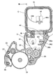
- FIG. 2 is a cross sectional view showing the developing unit 3 and the toner cartridge 4 according to the first embodiment.
- the developing unit 3 (i.e., the process unit) includes a photosensitive drum 31 as an image bearing body, a charging roller 32 as a charging device, a developing roller 33 as a developer bearing body, a developing blade 34 as a developer regulating member, a supplying roller 35 as a developer supplying member, a toner hopper 36 as a developer reservoir, a cleaning blade 37 as a cleaning member and a removed-toner conveying unit 38.
- the photosensitive drum 31 is an image bearing body on which a latent image is formed.
- the charging roller 32 uniformly charges the surface of the photosensitive drum 31.
- the developing roller 33 supplies the toner to the photosensitive drum 31 to develop the latent image on the photosensitive drum 31.
- the supplying roller 35 supplies the toner to the developing roller 33.
- the developing blade 34 regulates a thickness of a toner layer on the surface of the developing roller 33.
- the toner hopper 36 stores the toner supplied by the toner cartridge 4.
- the toner hopper 36 has a toner receiving opening 36a (as a developer receiving opening) and a feeding spiral 36b (as a developer distributing member).
- the toner receiving opening 36a is formed on a top of the toner hopper 36.
- the toner receiving opening 36a is located at a position corresponding to a toner supplying opening 42 (described later) of the toner cartridge 4.
- the toner receiving opening 36a is formed on a partial area of the toner hopper 36 in the longitudinal direction of the toner hopper 36 (i.e., parallel to an axial direction of the photosensitive drum 31). Further, in the longitudinal direction of the toner hopper 36, a length of the toner receiving opening 36a is shorter than the length of the toner hopper 36.
- the feeding spiral 36b has a shaft portion 361 whose center axis extends in the longitudinal direction of the toner hopper 36, and a spiral blade 362 protruding from the shaft portion 361 in a direction crossing a longitudinal direction of the shaft portion 361.
- the feeding spiral 36b (below the toner receiving portion 36a) is preferably disposed on a position shifted to a front side (i.e., a downstream side) with respect to a center of the toner receiving portion 36a in a rotating direction of an agitating-and-supplying member 43 (described later) of the toner cartridge 4.
- the cleaning blade 37 is configured to remove a residual toner that is not transferred to the printing medium but remains on the surface of the photosensitive drum 31.
- the removed-toner conveying unit 38 conveys the toner removed by the cleaning blade 37 toward the waste toner conveying unit 7 shown in FIG. 1 .
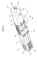
- FIGS. 3 and 4 are bottom perspective views showing the toner cartridge 4.
- the toner cartridge 4 includes an outer frame 41 (as a developer storage portion) with a toner supplying opening 42 (as an opening), an agitating-and-supplying member 43, and a toner supplying opening shutter 44 (as a shutter).
- the outer frame 41 has a box shape as shown in FIGS. 3 and 4 , and stores the toner therein.
- the toner supplying opening 42 is formed on the bottom of the outer frame 41.
- the toner supplying opening 42 is formed on a partial area of the outer frame 41 in a longitudinal direction of the outer frame 41. Further, in the longitudinal direction of the outer frame 41 (indicated by an arrow L in FIGS. 3 and 4 ), a length of the toner supplying opening 42 is shorter than a length of the outer frame 41.
- the toner supplying opening 42 is provided so as to encompass a center position of the outer frame 41 in the longitudinal direction.
- the agitating-and-supplying member 43 ( FIG. 2 ) is provided in the outer frame 41 so as to be rotatable about a center axis (i.e., a center line) parallel to the longitudinal direction of the outer frame 41.
- the toner supplying opening shutter 44 is movable in the longitudinal direction (indicated by the arrow L) of the outer frame 41.
- the toner supplying opening shutter 44 is movable between a position shown in FIG. 3 where the toner supplying opening shutter 44 closes the toner supplying opening 42, and a position shown in FIG. 4 where the toner supplying opening shutter 44 opens the toner supplying opening 42.
- the toner cartridge 4 includes the outer frame 41 and the toner supplying opening shutter 44 as described above, and further includes an agitating-and-supplying member driving gear 45 and a side cover 46.
- the outer frame 41 is in the form of a rectangular column having a top wall 41a, a bottom wall 41b, a first side wall 41c, a second side wall 41d, a third side wall 41e and a fourth side wall 41f.
- the walls 41a through 41f surround a space for storing the toner therein.
- the outer frame 41 is in the form of the rectangular column.
- the outer frame 41 can be in the form of, for example, a circular cylinder or a polygonal column such as a triangular column.
- Shaft-holes are formed on inner sides of the third wall 41e and the fourth wall 41f which are disposed on both ends of the outer frame 41 in the longitudinal direction. End portions (i.e., pins 43c and 43d shown in FIG. 5 ) of a shaft portion of the agitating-and-supplying member 43 engage and are supported by the shaft-holes.
- the toner supplying opening 42 is formed on the bottom wall 41b of the outer frame 41.
- the toner supplying opening 42' is located on a partial area in the longitudinal direction of the outer frame 41.
- the toner supplying opening 42 has a rectangular shape. Two longer edges of the toner supplying opening 42 are parallel to longer edges of the bottom wall 41b (i.e., parallel to the longitudinal direction of the outer frame 41).
- the toner supplying opening shutter 44 includes a top wall 44a, a bottom wall 44b, a first side wall 44c and a second side wall 44d.
- the top wall 44a, the bottom wall 44b, the first side wall 44c and the second side wall 44d surround the outer frame 41. That is, an inner surface of the top wall 44a faces an outer surface of the top wall 41a.
- An inner surface of the bottom wall 44b faces an outer surface of the bottom wall 41b.
- An inner surface of the first side wall 44c faces an outer surface of the first side wall 41c.
- An inner surface of the second side wall 44d faces an outer surface of the second side wall 41d.
- the toner supplying opening shutter 44 has two opened ends in the longitudinal direction of the outer frame 41, and the toner supplying opening shutter 44 is movable in the longitudinal direction of the outer frame 41 (i.e., in the direction indicated by the arrow L).
- a toner ejection opening 44e (as an ejection opening) is formed on the bottom wall 44b of the toner supplying opening shutter 44.
- the toner ejection opening 44e has substantially the same shape as the toner supplying opening 42.
- the toner supplying opening shutter 44 is moved in the longitudinal direction of the outer frame 41 as shown in FIG. 4 , the toner ejection opening 44e faces the toner supplying opening 42, so that the toner stored in the outer frame 41 is ejected outside (i.e., to the toner hopper 36).
- the toner supplying opening shutter 44 is moved in the longitudinal direction of the outer frame 41 as shown in FIG. 3 , the toner ejection opening 44e does not face the toner supplying opening 42 (instead, the toner ejection opening 44e faces the bottom wall 44b), so that an inner space of the outer frame 41 is closed.
- the agitating-and-supplying member driving gear 45 is provided on the fourth side wall 41f disposed on the end of the outer frame 41 in the longitudinal direction.
- the agitating-and-supplying member driving gear 45 transmits a rotation of a driving unit (not shown) provided on the developing unit 3 to the agitating-and-supplying member 43 in the outer frame 41.
- the side cover 46 is formed on the fourth side wall 41f so as to cover the agitating-and-supplying member driving gear 45.
- seal members such as sponges are provided on a gap between the toner supplying opening 42 and the bottom wall 44b of the toner supplying opening shutter 44, and a gap between the pins 43c and 43d ( FIG. 5 ) of the agitating-and-supplying member 43 and the shaft-holes (not shown) of the third and fourth side walls 41e and 41f.
- FIG. 5 is a perspective view showing the agitating-and-supplying member 43 provided in the toner cartridge 4. As shown in FIG. 5 , the agitating-and-supplying member 43 has a shaft portion 43a and an agitating portion 43b.
- the shaft portion 43a extends linearly, and has first and second pins (i.e., supporting pins) 43c and 43d provided on both ends in the longitudinal direction.
- the pins 43c and 43d are inserted into the shaft-holes (not shown) formed on the inner sides of the third and fourth side walls 41e and 41f of the outer frame 41, so that the shaft portion 43a is supported so as to be rotatable about a center axis of the shaft portion 43a.
- the shaft portion 43a has a mounting surface 43e extending along the center axis of the shaft portion 43a.
- FIG. 6 is a bottom view of the agitating-and-supplying member 43.
- the mounting surface 43e has a first area TA 1 at a center in the longitudinal direction, and second and third areas TA 2 and TA 3 on both sides of the first area TA 1 .
- the second area TA 2 is disposed on the first pin 43c, and the third area TA 3 is disposed on the second pin 43d.
- the mounting surface 43e 1 of the first area TA 1 is a surface whose normal line is perpendicular to the center axis of the shaft portion 43a.
- the mounting surface 43e 2 of the second area TA 2 is inclined so that a distance from the center axis of the shaft portion 43a increases toward the first pin 43c side.
- the mounting surface 43e 3 of the third area TA 3 is inclined so that a distance from the center axis of the shaft portion 43a increases toward the second pin 43d side.
- An angle between the mounting surface 43e 1 of the first area TA 1 and the mounting surface 43e 2 of the second area TA 2 , and an angle between the mounting surface 43e 1 of the first area TA 1 and the mounting surface 43e 3 of the third area TA 3 can be arbitrarily determined so as to cause the toner to move from the agitating portion 43b 2 fixed to the mounting surface 43e 2 and the agitating portion 43b 3 fixed to the mounting surface 43e 3 toward the agitating portion 43b 1 fixed to the mounting surface 43e 1 as described later.
- a length of the mounting surface 43e 1 of the first area TA 1 is shorter than the toner supplying opening 42 of the outer frame 41 in the longitudinal direction of the outer frame 41.
- the agitating portion 43b is fixed to the mounting surface 43e via a fixing means such as an adhesive agent.
- FIG. 7 is a front view of the agitating portion 43b.
- the agitating portion 43b has a substantially rectangular shape elongated along the shaft portion 43a.
- One of longer edges of the agitating portion 43b is fixed to the mounting surface 43e of the shaft portion 43a.
- the longer edge of the agitating portion 43b fixed to the mounting surface 43e will be referred to as a fixed longer edge F (also referred to as a fixed end).
- the agitating portion 43b is formed of a resilient member such as a film member.
- the agitating portion 43b is formed by bending a resilient member (for example, a film) having a flat shape. In this case, the resilient member is going to recover its original flat shape, so that a resilient force is generated.
- the agitating portion 43b can be formed of a material that generates a resilient force as described later.
- the agitating portion 43b is formed of polyethylene terephthalate (PET).
- the thickness of the agitating portion 43b is preferably in a range from 0.05 mm to 0.15 mm for generating a necessary resilient force.
- the most preferable thickness of the agitating portion 43b is preferably 0.10 mm.
- the length of the agitating portion 43b (fixed to the mounting surface 43e) is shorter than a distance between the inner surfaces of the third side wall 41e and the fourth side wall 41f of the outer frame 41.
- a distance between the center axis (indicated by a mark "Ax") of the shaft portion 43a and a longer edge of the agitating portion 43b farthest from the shaft portion 43a is longer than a maximum distance between the center axis of the shaft portion 43a and the inner surface of the outer frame 41.
- the agitating portion 43b contacts the inner surface of the outer frame 41 in a deflected manner.
- the longer edge of the agitating portion 43b farthest from the shaft portion 43a will be referred to as a distal longer edge D (also referred to as a distal end).
- the agitating portion 43b has a plurality of slits 43f extending from the distal longer edge D toward the fixed longer edge L of the agitating portion 43b.
- the agitating portion 43b has a first area KA 1 , a second area KA 2 and a third area KA 3 corresponding to the first area TA 1 , the second area TA 2 and the third area TA 3 of the mounting surface 43e of the shaft portion 43a.
- These areas KA 1 , KA 2 and KA 3 are separated by slits 43f. It is also possible to form additional slit(s) 43f within the areas KA 1 , KA 2 and KA 3 , in addition to the slits 43f separating the areas KA 1 , KA 2 and KA 3 .
- the numbers of the slits 43f within the areas KA 1 , KA 2 and KA 3 can be arbitrarily determined.
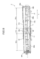
- FIG. 8 is a longitudinal sectional view of the toner cartridge 4, taken along line VIII-VIII in FIG. 2 .
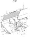
- FIG. 9 is a bottom perspective view of the toner cartridge 4. As shown in FIG. 8 , a length L1 of the agitating portion 43b 1 of the first area KA 1 in the longitudinal direction is shorter than or equal to a length L2 of the toner supplying opening 42 of the outer frame 41 in the longitudinal direction of the outer frame 41.
- the agitating portion 43b 1 of the first area KA 1 when the agitating portion 43b 1 of the first area KA 1 is in a position facing the toner supplying opening 42 of the outer frame 41, the agitating portion 43b 1 of the first area KA 1 protrudes outside the outer frame 41 via the toner supplying opening 42. Further, if the agitating portion 43b 1 has a suitable width (i.e.
- the agitating portion 43b 1 of the first area KA 1 protruding outside the outer frame 41 via the toner supplying opening 42 intrudes into the toner hopper 36 disposed below the toner supplying opening 42, and pushes the toner in the toner hopper 36 (more specifically, in the vicinity of the toner receiving opening 36a) toward the feeding spiral 36b.
- the width of the agitating portion 43b in a direction perpendicular to the center axis of the shaft portion 43a is determined so that the distance between the center axis of the shaft portion 43a and the distal longer edge D of the agitating portion 43b is longer than the maximum distance between the center axis of the shaft portion 43a and the inner surface of the outer frame 41. Further, the distance between the center axis of the shaft portion 43a and the distal longer edge D of the agitating portion 43b is longer than a distance between the center axis of the shaft portion 43a and the outer surface of the outer frame 41.
- the distance between the center axis of the shaft portion 43a and the distal longer edge D of the agitating portion 43b is longer than a distance between the center axis of the shaft portion 43a and the toner receiving opening 36a of the toner hopper 36.
- the distance between the center axis of the shaft portion 43a and the distal longer edge D of the agitating portion 43b has an upper limit so that the agitating portion 43b does not contact a device provided in the toner hopper 36 such as the feeding spiral 36.
- the slits 43f of the agitating portion 43b have lengths so as to extend from the distal longer edge D to reach the mounting surface 43.
- the lengths of the slits 43f can be arbitrarily determined.
- At least one of both sides of the agitating portion 43b 1 of the first area KA 1 has an inclined portion 43g so that a length of the agitating portion 43b 1 of the first area KA 1 (in a direction of the center axis of the shaft portion 43a) decreases toward the distal longer edge D.
- the length of the agitating portion 43b 1 of the first area KA 1 in the direction of the center axis of the shaft portion 43a is shorter at the distal longer edge D than at the fixed longer edge F.
- the agitating portion 43b 1 of the first area KA 1 is divided into two sections by the slit 43f.
- Each section of the agitating portion 43b 1 of the first area KA 1 has inclined portions 43g on both sides.
- the inclined portion 43g is inclined at an angle ⁇ with respect to a widthwise direction of the agitating portion 43 (i.e., a direction perpendicular to the center axis of the shaft portion 43a).
- the angle ⁇ is preferably in a range from 10 to 45 degrees, and more preferably in a range from 20 to 30 degrees.
- a length L3 of the agitating portion 43b 1 of the first area KA 1 protruding outside the outer frame 41 is shorter than a width L4 ( FIG. 9 ) of the toner supplying opening 42 in the widthwise direction of the toner cartridge 4.
- the agitating portion 43b 1 of the first area KA 1 has inclined portions 43g on both sides (i.e., on the sides facing the second area KA 2 and facing the third area KA 3 ) as shown in FIG. 7 .
- the agitating portion 43b 1 of the first area KA 1 has the inclined portion 43f on the side facing the third area KA 3 (i.e., the side that contacts the inner periphery 44f of the toner supplying opening 42).
- a length of the inclined portion 43f in the direction perpendicular to the center axis of the shaft portion 43a is longer than a length by which the agitating portion 43b 1 of the first area KA 1 protrudes outside the outer frame 41 via the toner ejection opening 44e.
- the mounting surface 43e 1 of the first area TA 1 is a surface whose normal line is perpendicular to the center axis of the shaft portion 43a.
- the mounting surface 43e 2 of the second area TA 2 is inclined so that a distance from the center axis of the shaft portion 43a increases toward the first pin 43c.
- the mounting surface 43e 3 of the third area TA 3 is inclined so that a distance from the center axis of the shaft portion 43a increases toward the second pin 43d.
- the agitating portion 43b has the first area KA 1 , the second area KA 2 and the third area KA 3 respectively corresponding to the first area TA 1 , the second area TA 2 and the third area TA 3 of the mounting surface 43e.
- the agitating portion 43b 2 of the second area KA 2 and the agitating portion 43b 3 of the third area KA 3 are inclined toward the agitating portion 43b 1 of the first area KA 1 . Therefore, when the shaft portion 43a rotates about the center axis, the toner is pushed by the agitating portion 43b 2 of the second area KA 2 and the agitating portion 43b 3 of the third area KA 3 and moves toward the agitating portion 43b 1 of the first area KA 1 . Thus, the toner is collected at the first area KA 1 , and is supplied to outside via the toner supplying opening 42 (disposed on a position corresponding to the first area KA 1 ).
- FIG. 10 is a cross sectional view for illustrating the operation of the toner cartridge 4 mounted to the developing unit 3, taken along line X-X in FIG. 4 .
- reference marks B, C and E indicate respective states of the agitating portion 43b as the agitating-and-supplying member 43 rotates in the direction indicated by the arrow A about the center axis of the shaft portion 43a.
- the agitating portion 43b (of the areas KA 1 , KA 2 and KA 3 ) contacts the inner surface of the outer frame 41 in such a manner that the agitating portion 43b is deflected as indicated by a reference mark "B".
- a deflecting direction of the agitating portion 43b is opposite to the rotating direction of the agitating-and-supplying member 43.
- a tip i.e., the distal longer end D
- the agitating portion 43b 1 of the first area KA 1 reaches the toner supplying opening 42 of the outer frame 41 as indicated by a reference mark "C" in FIG. 10 .
- the agitating portion 43b 1 of the first area KA 1 instantly changes its shape as indicated by a reference mark "E” in FIG. 10 .
- the agitating portion 43b 1 of the first area KA 1 changes its shape as indicated by the reference mark "E" to release its deflection, the agitating portion 43b 1 pushes the toner into the toner hopper 36. Further, the agitating portion 43b 1 disperses the toner stagnating in the vicinity of the toner receiving opening 36a of the toner hopper 36, and pushes the toner into the toner hopper 36 (to be more specific, toward the feeding spiral 36b).
- the agitating portion 43b 1 of the first area KA 1 When the agitating portion 43b 1 of the first area KA 1 is in a state shown by the reference mark "E", the agitating portion 43b 1 contacts an inner periphery 42a of the toner supplying opening 42.
- the tip (i.e., the distal longer edge D) of the agitating portion 43b 1 positions at a rear side with respect to the inner periphery 42a of the toner supplying opening 42 in a rotating direction of the agitating-and-supplying member 43.
- An angle ⁇ (which is greater than 0) is formed between the agitating portion 43b 1 and the inner periphery 42a of the toner supplying opening 42.
- the toner supplying opening shutter 44 When the toner supplying opening shutter 44 is moved to close the toner supply opening 42 in a state where the agitating portion 43b 1 protrudes outside the outer frame 41, the toner supplying opening shutter 44 pushes the inclined portion 43g of the agitating portion 43b 1 of the first area KA 1 , so that the agitating portion 43b 1 of the first area KA 1 is pushed into the outer frame 41. Thus, the agitating portion 43b is not nipped by the toner supplying opening shutter 44 and the outer frame 41.
- the agitating-and-supplying member 43 When the agitating-and-supplying member 43 further rotates in the direction indicated by the arrow A from the state indicated by the reference mark "E", the agitating portion 43b 1 of the first area KA 1 is deflected in a direction to increase its deflection, and is retracted inside the outer frame 41.
- the agitating portion 43b of the agitating-and-supplying member 43 protrudes outside the toner cartridge 4 and intrudes into the toner hopper 36 via the toner supplying opening 42, and therefore the stagnation of the toner in the toner hopper 36 (more specifically, in the vicinity of the toner receiving opening 36a) can be prevented.
- the second embodiment is different from the first embodiment in the structure of the agitating-and-supplying member 43 (243).
- an agitating-and-supplying member 243 according to the second embodiment and its related components will be described.
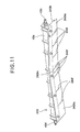
- FIG. 11 is a perspective view showing the agitating-and-supplying member 243 of the second embodiment of the present invention.
- the agitating-and-supplying member 243 includes a shaft portion 43a and an agitating portion 243b.
- the shaft portion 43a is the same as that of the first embodiment, but the agitating portion 243b is different from the agitating portion 43b of the first embodiment. Therefore, a structure of the agitating portion 243b will be described.
- FIG. 12 is a front view of the agitating portion 243b. As shown in FIG. 12 , a longitudinal direction of the agitating portion 243b is parallel to the center axis of the shaft portion 43a. An end of the agitating portion 243b in a direction perpendicular to the center axis of the shaft portion 43a (i.e., a fixed longer edge F) is fixed to the mounting surface 43e of the shaft portion 43a as in the first embodiment. Another longer edge of the agitating portion 243b (opposite to the fixed longer edge F) will be referred to as a distal longer edge D.
- a distal longer edge D Another longer edge of the agitating portion 243b (opposite to the fixed longer edge F)
- the agitating portion 243b has the first area KA 1 , the second area KA 2 and the third area KA 3 separated by slits 243f as described in the first embodiment.
- a width of the agitating portion 243b 1 of the first area KA 1 (in the direction perpendicular to the center axis of the shaft portion 43a) is the same as that of the first embodiment.
- the widths (in the direction perpendicular to the center axis of the shaft portion 43a) of the agitating portion 243b 2 of the second area KA 2 and the agitating portion 243b 3 of the third area KA 3 are shorter than those of the first embodiment.
- a distance between the center axis (Ax) of the shaft portion 43a and the distal longer edge D of the agitating portion 243b 2 of the second area KA 2 is longer than a maximum distance between the center axis of the shaft portion 43a and the inner surface of the outer frame 41.
- a distance between the center axis (Ax) of the shaft portion 43a and the distal longer edge D of the agitating portion 243b 3 of the third area KA 3 is longer than the maximum distance between the center axis of the shaft portion 43a and the inner surface of the outer frame 41. That is, the agitating portion 243b 2 of the second area KA 2 and the agitating portion 243b 3 of the third area KA 3 both contact the inner surface of the outer frame 41.
- the agitating portion 243b 2 of the second area KA 2 and the agitating portion 243b 3 of the third area KA 3 sweep the toner in a relatively upright manner, as compared with the agitating portion 43 of the first embodiment. As a result, the toner can efficiently be swept.
- the agitating portion 243b 2 of the second area KA 2 and the agitating portion 243b 3 of the third area KA 3 contact the inner surface of the outer frame 41, the agitating portion 243b 2 of the second area KA 2 and the agitating portion 243b 3 of the third area KA 3 can still be further deformed. Therefore, a resistance to the rotation of the agitating-and-supplying member 243 caused by the toner in the outer frame 41 is reduced by the deformation of the agitating portion 243b 2 of the second area KA 2 and the agitating portion 243b 3 of the third area KA 3 , with the result that a rotational load of the agitating-and-supplying member 243 is reduced.
- the length of the agitating portion 243b 1 of the first area KA 1 (in the longitudinal direction of the agitating portion 243b) is shorter than the length of the toner supplying opening 42 in the longitudinal direction of the outer frame 41, so that the agitating portion 243b 1 of the first area KA 1 can enter into the toner hopper 36.
- At least one of both sides of the agitating portion 243b 1 of the first area KA 1 has an inclined portion 243g so that a length of the agitating portion 243b 1 of the first area KA 1 (in the direction of the center axis of the shaft portion 43a) decreases toward the distal longer edge D.
- the length of the agitating portion 243b 1 of the first area KA 1 in the direction of the center axis of the shaft portion 43a is shorter at the distal longer edge D than at the fixed longer edge F.
- FIG. 13 is a cross sectional view showing the toner cartridge 4 mounted to the developing unit 3, corresponding to the cross section taken along line X-X in FIG. 4 .
- the agitating portion 243b 2 of the second area KA 2 and the agitating portion 243b 3 of the third area KA 3 are less deformed than the agitating portion 243b 1 of the first area KA 1 while sweeping the toner stored in the outer frame 41. That is, the agitating portion 243b 2 of the second area KA 2 and the agitating portion 243b 3 of the third area KA 3 sweep the toner in a relatively upright manner. Therefore, the toner can be efficiently swept.
- the agitating portion 243b 2 of the second area KA 2 and the agitating portion 243b 3 of the third area KA 3 can be further deformed even when the agitating portion 243b 2 of the second area KA 2 and the agitating portion 243b 3 of the third area KA 3 contact the inner surface of the outer frame 41, a resistance to the rotation of the agitating-and-supplying member 243 (caused by the toner) can be reduced, and a rotational load of the agitating-and-supplying member 243 is reduced.
- the third embodiment is different from the first embodiment in structure of the agitating-and-supplying member 43 (343).
- an agitating-and-supplying member 343 of the third embodiment and its related components will be described.
- FIG. 14 is a perspective view showing the agitating-and-supplying member 343 according to the third embodiment of the present invention.
- the agitating-and-supplying member 343 includes a shaft portion 343a and an agitating portion 343b.
- differences between the agitating-and-supplying member 343 of the third embodiment and the agitating-and-supplying member 43 of the first embodiment will be described.
- FIG. 15 is a bottom view of the agitating-and-supplying member 343.
- the shaft portion 343a linearly extends, and has first and second pins 343c and 343d are provided on both ends in the longitudinal direction.
- the pins 343c and 343d i.e., supporting pins
- the pins 343c and 343d are inserted into the shaft-holes formed on the inner sides of the third side wall 41e and the fourth side wall 41f (see, FIG. 8 ) of the outer frame 41, so that the shaft portion 343a is rotatable about the center axis.
- the shaft portion 343a has a mounting surface 343e extending in a direction of the center axis of the shaft portion 343a.
- the mounting surface 343 is formed as a flat surface.
- the agitating portion 343b is fixed to the mounting surface 343e using a fixing means such as an adhesive agent.
- FIG. 16 is a front view of the agitating portion 343b. As shown in FIG. 16 , a longitudinal direction of the agitating portion 343b is parallel to the center axis of the shaft portion 343a. An end of the agitating portion 343b in a direction perpendicular to the center axis of the shaft portion 343a (i.e., a fixed longer edge F) is fixed to the mounting surface 343e of the shaft portion 343a. Another longer edge of the agitating portion 343a (opposite to the fixed longer edge F) will be referred to as a distal longer edge D.
- the shaft portion 343b has a first area KA 1 , a second area KA 2 and a third area KA 3 separated by slits 343f as described in the first embodiment.
- a width of the agitating portion 343b 1 of the first area KA 1 is the same as that of the first embodiment.
- a width of the agitating portion 343b 2 of the second area KA 2 gradually decreases toward the first pin 343c.
- a width of the agitating portion 343b 3 of the third area KA 3 gradually decreases toward the second pin 343d.
- a distance between the center axis of the shaft portion 343a and the distal longer edge D of the agitating portion 343b 2 of the second area KA 2 gradually decreases toward the first pin 343c.
- a distance between the center axis of the shaft portion 343a and the distal longer edge D of the agitating portion 343b 3 of the third area KA 3 gradually decreases toward the second pin 343d.
- the distance between the center axis of the shaft portion 343a and the distal longer edge D of the agitating portion 343b 2 of the second area KA 2 is longer than a maximum distance between the center axis of the shaft portion 343a and the inner surface of the outer frame 41.
- the distance between the center axis of the shaft portion 343a and the distal longer edge D of the agitating portion 343b 3 of the third area KA 3 is longer than the maximum distance between the center axis of the shaft portion 343a and the inner surface of the outer frame 41. That is, the agitating portion 343b 2 of the second area KA 2 and the agitating portion 343b 3 of the third area KA 3 both contact the inner surface of the outer frame 41.
- the agitating portion 343b contacts the inner surface of the outer frame 41 in a deflected manner. Due to the above described widths of the agitating portion 343b 2 of the second area KA 2 and the agitating portion 343b 3 of the third area KA 3 , the deflection amounts of the agitating portion 343b 2 of the second area KA 2 and the agitating portion 343b 3 of the third area KA 3 decrease toward either end of the agitating portion 343b in the longitudinal direction.
- FIG. 17 is a longitudinal sectional view of the toner cartridge 4, taken along line VIII-VIII in FIG. 2 .
- outside parts (in the longitudinal direction of the agitating portion 343b) of the agitating portion 343b 2 of the second area KA 2 and the agitating portion 343b 3 of the third area KA 3 sweep the toner stored in the outer frame 41 in a relatively upright manner, and therefore a resistance to the rotation of the agitating-and-supplying member 343 (caused by the toner) is reduced, so that a rotational load of the agitating-and-supplying member 343 is reduced.
- the agitating portion 343b 2 of the second area KA 2 and the agitating portion 343b 3 of the third area KA 3 shift ahead of (i.e., to a front side of) the agitating portion 343b 1 of the first area KA 1 in the rotating direction of the agitating portion 343.
- the toner is caused to move from the agitating portion 343b 2 of the second area KA 2 and the agitating portion 343b 3 of the third area KA 3 toward the agitating portion 343b 1 of the first area KA 1 .
- the toner in the outer frame 41 is collected at the agitating portion 343b 1 of the first area KA 1 , and is supplied to the toner hopper 36 via the toner supplying opening 42. Therefore, the toner stored in the outer frame 41 is efficiently supplied to the toner hopper 36 via the toner supplying opening 42.
- the agitating portion 343b is fixed to the mounting surface 343e of the shaft portion 343a formed as a flat surface.
- mount the agitating portion 343b to a linearly extending shaft connecting the first and second pins 343c and 343d.
- mount the agitating portion 343b to the mounting surface 43e with inclined surfaces (see FIG. 6 ) as described in the first embodiment.
- the fourth embodiment is different from the first embodiment in structures of the toner supplying opening shutter 44 (444) and the agitating portion 43b (443b).
- a toner supplying opening shutter 444 and an agitating portion 443b of the fourth embodiment and their related components will be described.
- FIG. 18 is a bottom perspective view showing the toner supplying opening shutter 444 and the agitating portion 443b.
- the toner supplying opening shutter 444 of the fourth embodiment has the ejection opening 444e formed on the bottom wall 444b.
- An inner periphery 444f of the ejection opening 444e (on a rear side in the moving direction of the toner supplying opening shutter 444 to close the toner supplying opening 444e) is inclined with respect to the moving direction of the toner supplying opening shutter 444.
- FIG. 19 is a bottom view showing the toner ejection opening 444e.
- the inner periphery 444f of the toner ejection opening 444e is inclined so that an opening length (indicated by an arrow S) of the ejection opening 444e in the longitudinal direction of the outer frame 41 decreases in a rotating direction of the agitating portion 443b (indicated by an arrow R).
- the opening length S of the ejection opening 444e is shorter at a front side (i.e., a downstream side) in the rotating direction of the agitating portion 443b than at a rear side (i.e., an upstream side) in the rotating direction of the agitating portion 443b.
- An angle ⁇ of the inner periphery 444f with respect to a widthwise direction of the toner supplying opening shutter 444 is preferably in a range from 10 to 45 degrees, and more preferably in a range from 20 to 30 degrees.
- the agitating portion 443b of the fourth embodiment is different from the agitating portion 43b of the first embodiment in that the agitating portion 443b has no inclined portion 43g ( FIG. 7 ).
- the agitating portion 443b of the fourth embodiment is the same as the agitating portion 43b of the first embodiment in other respects.
- the inner periphery 444f of the toner ejection opening 444e on the rear side in the moving direction of the toner supplying opening shutter 444 for closing the toner supplying opening 42 is inclined as described above. Therefore, when the toner supplying opening shutter 444 is moved to close the toner supplying opening 42 in a state where the agitating portion 443b protrudes outside the outer frame 41 via the toner supplying opening 42 and the toner ejection opening 444e, the inner periphery 444f of the toner ejection opening 444e contacts a side edge of the agitating portion 443b, and pushes the agitating portion 443b into the outer frame 41. Thus, the agitating portion 443b is not nipped by the toner supplying opening shutter 444 and the outer frame 41.
- the agitating portion 443b is not required to have the inclined portion 43g ( FIG. 7 ). Therefore, a relatively large area of the agitating portion 443b protrudes into the toner hopper 36 via the toner supplying opening 42 and the toner ejection opening 444e. Thus, the toner stored in the toner hopper 36 is efficiently pushed toward the feeding spiral 36a ( FIG. 2 ).
Landscapes
- Physics & Mathematics (AREA)
- General Physics & Mathematics (AREA)
- Dry Development In Electrophotography (AREA)
- Mixers Of The Rotary Stirring Type (AREA)
Abstract
Description
- The present invention relates to a developer storage container for storing a developer, and relates to a developing device and an image forming apparatus using the developer storage container.
- In a general electrophotographic printer, a surface of a photosensitive drum is uniformly charged by a charging device, and then exposed by an exposing device to form a latent image. The latent image is developed by a developing device to form a toner image. The toner image is transferred to a printing medium by a transfer unit, and is fixed to the printing medium by a fixing device.
- As the developing device repeatedly performs the developing process, the amount of a toner (i.e., a developer) in the developing device decreases. Therefore, the developing device has a toner cartridge detachably mounted to a main body of the developing device. When the toner stored in the developing device is used up, the toner cartridge is replaced with new one, so as to replenish the toner to the developing device.
- The toner cartridge has a toner supplying opening (i.e., a developer supplying opening) through which the toner is supplied to a toner hopper in the main body of the developing device. The toner supplying opening is formed to be relatively small (particularly, with respective to a length of the toner cartridge), in order to prevent decrease in rigidity of the toner cartridge, to prevent leakage of the toner, and to prevent scattering of the toner during a replacement operation of the toner cartridge.
- The main body of the developing device has a toner receiving opening through which the toner is supplied to the toner hopper. The toner receiving opening is provided in a partial area in the longitudinal direction of the developing device, corresponding to the toner supplying opening of the toner cartridge. The developing device has an agitating-and-conveying unit provided in the toner hopper, which agitates and conveys the toner throughout a length of the developing device (see, Japanese Laid-open Patent Publication No.
2007-264165 - However, in the conventional developing device, a density of the toner in the vicinity of the toner receiving opening tends to be high, and therefore a fluidity of the toner tends to decrease. Therefore, a stagnation of the toner may occur in the vicinity of the toner receiving opening, and the toner may not be distributed throughout the developing device.
- The present invention is intended to solve the above described problems, and an object of the present invention is to provide a developer storage container, a developing device and an image forming apparatus capable of effectively preventing a stagnation of a developer supplied via an opening of the developer storage container.
- The present invention provides a developer storage container including a developer storage portion that stores a developer and has an opening for supplying the developer. An agitating-and-supplying member is rotatably provided in the developer storage portion. The agitating-and-supplying member has a shaft portion and an agitating portion. The agitating portion has a fixed end and a distal end opposite to each other. The fixed end of the agitating portion is fixed to the shaft portion. The agitating portion has an area corresponding to the opening. In the area, a distance between a center axis of the shaft portion and the distal end of the agitating portion is longer than a distance between the center axis of the shaft portion and an outer wall of the developer storage portion.
- With such a configuration, it becomes possible to prevent a stagnation of the developer supplied via the opening of the developer storage container.
- The present invention also provides a developing device including the above described developer storage container.
- The present invention also provides an image forming apparatus including the above described developer storage container.
- Further scope of applicability of the present invention will become apparent from the detailed description given hereinafter. However, it should be understood that the detailed description and specific embodiments, while indicating preferred embodiments of the invention, are given by way of illustration only, since various changes and modifications within the spirit and scope of the invention will become apparent to those skilled in the art from this detailed description.
- In the attached drawings:
-
FIG. 1 is a schematic view showing a configuration of an image forming apparatus according to the first embodiment; -
FIG. 2 is a cross sectional view showing a developing unit and a toner cartridge according to the first embodiment; -
FIG. 3 is a bottom perspective view showing the toner cartridge according to the first embodiment; -
FIG. 4 is a bottom perspective view showing the toner cartridge according to the first embodiment; -
FIG. 5 is a perspective view showing an agitating-and-supplying member provided in the toner cartridge according to the first embodiment; -
FIG. 6 is a bottom view showing the agitating-and-supplying member provided in the toner cartridge according to the first embodiment; -
FIG. 7 is a front view showing the agitating-and-supplying member according to the first embodiment; -
FIG. 8 is a longitudinal sectional view showing the toner cartridge according to the first embodiment, taken along line VIII-VIII inFIG. 2 ; -
FIG. 9 is a bottom perspective view showing the toner cartridge according to the first embodiment; -
FIG. 10 is a cross sectional view for illustrating an operation of the toner cartridge mounted to the developing unit according to the first embodiment; -
FIG. 11 is a perspective view showing an agitating-and-supplying member according to the second embodiment; -
FIG. 12 is a front view showing the agitating-and-supplying member according to the second embodiment; -
FIG. 13 is a cross sectional view showing a toner cartridge and a developing unit according to the second embodiment, taken along line VIII-VIII inFIG. 2 ; -
FIG. 14 is a perspective view showing an agitating-and-supplying member according to the third embodiment; -
FIG. 15 is a bottom view showing the agitating-and-supplying member according to the third embodiment; -
FIG. 16 is a front view showing the agitating-and-supplying member according to the third embodiment; -
FIG. 17 is a longitudinal sectional view showing a toner cartridge according to the third embodiment, taken along line VIII-VIII inFIG. 2 ; -
FIG. 18 is a bottom perspective view showing a toner supplying opening shutter and an agitating portion according to the fourth embodiment, and -
FIG. 19 is a bottom view showing a toner ejection opening according to the fourth embodiment. - Hereinafter, embodiments of the present invention will be described with reference to drawings.
-
FIG. 1 is a schematic view showing a configuration of animage forming apparatus 1 according to the first embodiment of the present invention. As shown inFIG. 1 , theimage forming apparatus 1 includes a developingdevice 2, exposingunits unit 8, afeeding cassette 9 and afixing unit 10. - The developing
device 2 includes developing units (also referred to as process units) 3k, 3c, 3m and 3y for forming toner images of black, cyan, magenta and yellow, andtoner cartridges device 2 further includes a wastetoner storage container 5 and a wastetoner conveying unit 7. - The developing
device 2 has an integral structure, and is detachably mounted to a main body of theimage forming apparatus 1. - The developing
units - The
toner cartridges units toner cartridges units - The waste
toner storage container 5 collectively stores the waste toner ejected from the developingunits - The
exposing units units exposing units photosensitive drums 31 to form latent images. Theexposing units exposing units - The
transfer unit 8 includestransfer rollers photosensitive drums 31 of the developingunits transfer belt 81 passing between the respectivephotosensitive drums 31 and thetransfer rollers transfer unit 8 transfers toner images from thephotosensitive drums 31 to a printing medium. - The feeding
cassette 9 stores and feeds the printing media such as papers to the developingunits transfer unit 8. - The fixing
unit 10 includes a fixingroller 11 and apressure roller 12 which fix the toner image to the printing medium by application of heat and pressure. - Hereinafter, the developing
units units 3. Thetoner cartridges toner cartridges 4. The exposingunits -
FIG. 2 is a cross sectional view showing the developingunit 3 and thetoner cartridge 4 according to the first embodiment. - As shown in
FIG. 2 , the developing unit 3 (i.e., the process unit) includes aphotosensitive drum 31 as an image bearing body, a chargingroller 32 as a charging device, a developingroller 33 as a developer bearing body, a developingblade 34 as a developer regulating member, a supplyingroller 35 as a developer supplying member, atoner hopper 36 as a developer reservoir, acleaning blade 37 as a cleaning member and a removed-toner conveying unit 38. - The
photosensitive drum 31 is an image bearing body on which a latent image is formed. The chargingroller 32 uniformly charges the surface of thephotosensitive drum 31. The developingroller 33 supplies the toner to thephotosensitive drum 31 to develop the latent image on thephotosensitive drum 31. The supplyingroller 35 supplies the toner to the developingroller 33. The developingblade 34 regulates a thickness of a toner layer on the surface of the developingroller 33. Thetoner hopper 36 stores the toner supplied by thetoner cartridge 4. - The
toner hopper 36 has atoner receiving opening 36a (as a developer receiving opening) and afeeding spiral 36b (as a developer distributing member). - The
toner receiving opening 36a is formed on a top of thetoner hopper 36. Thetoner receiving opening 36a is located at a position corresponding to a toner supplying opening 42 (described later) of thetoner cartridge 4. In this embodiment, thetoner receiving opening 36a is formed on a partial area of thetoner hopper 36 in the longitudinal direction of the toner hopper 36 (i.e., parallel to an axial direction of the photosensitive drum 31). Further, in the longitudinal direction of thetoner hopper 36, a length of thetoner receiving opening 36a is shorter than the length of thetoner hopper 36. - The
feeding spiral 36b has ashaft portion 361 whose center axis extends in the longitudinal direction of thetoner hopper 36, and aspiral blade 362 protruding from theshaft portion 361 in a direction crossing a longitudinal direction of theshaft portion 361. By the rotation of thefeeding spiral 36b, the toner supplied into the toner hopper 36 (via thetoner receiving opening 36a) is conveyed in the longitudinal direction of thetoner hopper 36 along a surface of thespiral blade 362 of thefeeding spiral 36b. Thefeeding spiral 36b (below thetoner receiving portion 36a) is preferably disposed on a position shifted to a front side (i.e., a downstream side) with respect to a center of thetoner receiving portion 36a in a rotating direction of an agitating-and-supplying member 43 (described later) of thetoner cartridge 4. - The
cleaning blade 37 is configured to remove a residual toner that is not transferred to the printing medium but remains on the surface of thephotosensitive drum 31. The removed-toner conveying unit 38 conveys the toner removed by thecleaning blade 37 toward the wastetoner conveying unit 7 shown inFIG. 1 . -
FIGS. 3 and4 are bottom perspective views showing thetoner cartridge 4. - As shown in
FIGS. 3 and4 , thetoner cartridge 4 includes an outer frame 41 (as a developer storage portion) with a toner supplying opening 42 (as an opening), an agitating-and-supplyingmember 43, and a toner supplying opening shutter 44 (as a shutter). - The
outer frame 41 has a box shape as shown inFIGS. 3 and4 , and stores the toner therein. - The
toner supplying opening 42 is formed on the bottom of theouter frame 41. In this embodiment, thetoner supplying opening 42 is formed on a partial area of theouter frame 41 in a longitudinal direction of theouter frame 41. Further, in the longitudinal direction of the outer frame 41 (indicated by an arrow L inFIGS. 3 and4 ), a length of thetoner supplying opening 42 is shorter than a length of theouter frame 41. In this embodiment, thetoner supplying opening 42 is provided so as to encompass a center position of theouter frame 41 in the longitudinal direction. - The agitating-and-supplying member 43 (
FIG. 2 ) is provided in theouter frame 41 so as to be rotatable about a center axis (i.e., a center line) parallel to the longitudinal direction of theouter frame 41. - The toner supplying
opening shutter 44 is movable in the longitudinal direction (indicated by the arrow L) of theouter frame 41. The toner supplyingopening shutter 44 is movable between a position shown inFIG. 3 where the toner supplyingopening shutter 44 closes thetoner supplying opening 42, and a position shown inFIG. 4 where the toner supplyingopening shutter 44 opens thetoner supplying opening 42. - The
toner cartridge 4 includes theouter frame 41 and the toner supplyingopening shutter 44 as described above, and further includes an agitating-and-supplyingmember driving gear 45 and aside cover 46. - The
outer frame 41 is in the form of a rectangular column having atop wall 41a, abottom wall 41b, afirst side wall 41c, asecond side wall 41d, athird side wall 41e and afourth side wall 41f. Thewalls 41a through 41f surround a space for storing the toner therein. - In this embodiment, the
outer frame 41 is in the form of the rectangular column. However, theouter frame 41 can be in the form of, for example, a circular cylinder or a polygonal column such as a triangular column. - Shaft-holes (not shown) are formed on inner sides of the
third wall 41e and thefourth wall 41f which are disposed on both ends of theouter frame 41 in the longitudinal direction. End portions (i.e., pins 43c and 43d shown inFIG. 5 ) of a shaft portion of the agitating-and-supplyingmember 43 engage and are supported by the shaft-holes. - The
toner supplying opening 42 is formed on thebottom wall 41b of theouter frame 41. The toner supplying opening 42' is located on a partial area in the longitudinal direction of theouter frame 41. Thetoner supplying opening 42 has a rectangular shape. Two longer edges of thetoner supplying opening 42 are parallel to longer edges of thebottom wall 41b (i.e., parallel to the longitudinal direction of the outer frame 41). - The toner supplying
opening shutter 44 includes atop wall 44a, abottom wall 44b, afirst side wall 44c and asecond side wall 44d. Thetop wall 44a, thebottom wall 44b, thefirst side wall 44c and thesecond side wall 44d surround theouter frame 41. That is, an inner surface of thetop wall 44a faces an outer surface of thetop wall 41a. An inner surface of thebottom wall 44b faces an outer surface of thebottom wall 41b. An inner surface of thefirst side wall 44c faces an outer surface of thefirst side wall 41c. An inner surface of thesecond side wall 44d faces an outer surface of thesecond side wall 41d. The toner supplyingopening shutter 44 has two opened ends in the longitudinal direction of theouter frame 41, and the toner supplyingopening shutter 44 is movable in the longitudinal direction of the outer frame 41 (i.e., in the direction indicated by the arrow L). - A toner ejection opening 44e (as an ejection opening) is formed on the
bottom wall 44b of the toner supplyingopening shutter 44. Thetoner ejection opening 44e has substantially the same shape as thetoner supplying opening 42. When the toner supplyingopening shutter 44 is moved in the longitudinal direction of theouter frame 41 as shown inFIG. 4 , the toner ejection opening 44e faces thetoner supplying opening 42, so that the toner stored in theouter frame 41 is ejected outside (i.e., to the toner hopper 36). In contrast, when the toner supplyingopening shutter 44 is moved in the longitudinal direction of theouter frame 41 as shown inFIG. 3 , thetoner ejection opening 44e does not face the toner supplying opening 42 (instead, the toner ejection opening 44e faces thebottom wall 44b), so that an inner space of theouter frame 41 is closed. - The agitating-and-supplying
member driving gear 45 is provided on thefourth side wall 41f disposed on the end of theouter frame 41 in the longitudinal direction. The agitating-and-supplyingmember driving gear 45 transmits a rotation of a driving unit (not shown) provided on the developingunit 3 to the agitating-and-supplyingmember 43 in theouter frame 41. - The side cover 46 is formed on the
fourth side wall 41f so as to cover the agitating-and-supplyingmember driving gear 45. - In order to prevent leakage of the toner, seal members such as sponges are provided on a gap between the
toner supplying opening 42 and thebottom wall 44b of the toner supplyingopening shutter 44, and a gap between thepins FIG. 5 ) of the agitating-and-supplyingmember 43 and the shaft-holes (not shown) of the third andfourth side walls -
FIG. 5 is a perspective view showing the agitating-and-supplyingmember 43 provided in thetoner cartridge 4. As shown inFIG. 5 , the agitating-and-supplyingmember 43 has ashaft portion 43a and an agitatingportion 43b. - The
shaft portion 43a extends linearly, and has first and second pins (i.e., supporting pins) 43c and 43d provided on both ends in the longitudinal direction. Thepins fourth side walls outer frame 41, so that theshaft portion 43a is supported so as to be rotatable about a center axis of theshaft portion 43a. - The
shaft portion 43a has a mountingsurface 43e extending along the center axis of theshaft portion 43a.FIG. 6 is a bottom view of the agitating-and-supplyingmember 43. As shown inFIG. 6 , the mountingsurface 43e has a first area TA1 at a center in the longitudinal direction, and second and third areas TA2 and TA3 on both sides of the first area TA1. The second area TA2 is disposed on thefirst pin 43c, and the third area TA3 is disposed on thesecond pin 43d. - The mounting
surface 43e1 of the first area TA1 is a surface whose normal line is perpendicular to the center axis of theshaft portion 43a. The mountingsurface 43e2 of the second area TA2 is inclined so that a distance from the center axis of theshaft portion 43a increases toward thefirst pin 43c side. The mountingsurface 43e3 of the third area TA3 is inclined so that a distance from the center axis of theshaft portion 43a increases toward thesecond pin 43d side. - An angle between the mounting
surface 43e1 of the first area TA1 and the mountingsurface 43e2 of the second area TA2, and an angle between the mountingsurface 43e1 of the first area TA1 and the mountingsurface 43e3 of the third area TA3 can be arbitrarily determined so as to cause the toner to move from the agitatingportion 43b2 fixed to the mountingsurface 43e2 and the agitatingportion 43b3 fixed to the mountingsurface 43e3 toward the agitatingportion 43b1 fixed to the mountingsurface 43e1 as described later. A length of the mountingsurface 43e1 of the first area TA1 is shorter than thetoner supplying opening 42 of theouter frame 41 in the longitudinal direction of theouter frame 41. - The agitating
portion 43b is fixed to the mountingsurface 43e via a fixing means such as an adhesive agent. -
FIG. 7 is a front view of the agitatingportion 43b. The agitatingportion 43b has a substantially rectangular shape elongated along theshaft portion 43a. One of longer edges of the agitatingportion 43b is fixed to the mountingsurface 43e of theshaft portion 43a. Hereinafter, the longer edge of the agitatingportion 43b fixed to the mountingsurface 43e will be referred to as a fixed longer edge F (also referred to as a fixed end). - The agitating
portion 43b is formed of a resilient member such as a film member. For example, the agitatingportion 43b is formed by bending a resilient member (for example, a film) having a flat shape. In this case, the resilient member is going to recover its original flat shape, so that a resilient force is generated. The agitatingportion 43b can be formed of a material that generates a resilient force as described later. In this embodiment, the agitatingportion 43b is formed of polyethylene terephthalate (PET). - The thickness of the agitating
portion 43b is preferably in a range from 0.05 mm to 0.15 mm for generating a necessary resilient force. The most preferable thickness of the agitatingportion 43b is preferably 0.10 mm. - In the longitudinal direction of the
outer frame 41, the length of the agitatingportion 43b (fixed to the mountingsurface 43e) is shorter than a distance between the inner surfaces of thethird side wall 41e and thefourth side wall 41f of theouter frame 41. - When the agitating
portion 43b is held in a flat shape as shown inFIG. 7 , a distance between the center axis (indicated by a mark "Ax") of theshaft portion 43a and a longer edge of the agitatingportion 43b farthest from theshaft portion 43a is longer than a maximum distance between the center axis of theshaft portion 43a and the inner surface of theouter frame 41. - Therefore, in a state where the agitating-and-supplying
member 43 is mounted in theouter frame 41, the agitatingportion 43b contacts the inner surface of theouter frame 41 in a deflected manner. Hereinafter, the longer edge of the agitatingportion 43b farthest from theshaft portion 43a will be referred to as a distal longer edge D (also referred to as a distal end). - The agitating
portion 43b has a plurality ofslits 43f extending from the distal longer edge D toward the fixed longer edge L of the agitatingportion 43b. - The agitating
portion 43b has a first area KA1, a second area KA2 and a third area KA3 corresponding to the first area TA1, the second area TA2 and the third area TA3 of the mountingsurface 43e of theshaft portion 43a. These areas KA1, KA2 and KA3 are separated byslits 43f. It is also possible to form additional slit(s) 43f within the areas KA1, KA2 and KA3, in addition to theslits 43f separating the areas KA1, KA2 and KA3. The numbers of theslits 43f within the areas KA1, KA2 and KA3 can be arbitrarily determined. -
FIG. 8 is a longitudinal sectional view of thetoner cartridge 4, taken along line VIII-VIII inFIG. 2 .FIG. 9 is a bottom perspective view of thetoner cartridge 4. As shown inFIG. 8 , a length L1 of the agitatingportion 43b1 of the first area KA1 in the longitudinal direction is shorter than or equal to a length L2 of thetoner supplying opening 42 of theouter frame 41 in the longitudinal direction of theouter frame 41. - Therefore, as shown in
FIG. 9 , when the agitatingportion 43b1 of the first area KA1 is in a position facing thetoner supplying opening 42 of theouter frame 41, the agitatingportion 43b1 of the first area KA1 protrudes outside theouter frame 41 via thetoner supplying opening 42. Further, if the agitatingportion 43b1 has a suitable width (i.e. a dimension perpendicular to the center axis of theshaft portion 43a), the agitatingportion 43b1 of the first area KA1 (protruding outside theouter frame 41 via the toner supplying opening 42) intrudes into thetoner hopper 36 disposed below thetoner supplying opening 42, and pushes the toner in the toner hopper 36 (more specifically, in the vicinity of thetoner receiving opening 36a) toward thefeeding spiral 36b. - As described above, the width of the agitating
portion 43b in a direction perpendicular to the center axis of theshaft portion 43a is determined so that the distance between the center axis of theshaft portion 43a and the distal longer edge D of the agitatingportion 43b is longer than the maximum distance between the center axis of theshaft portion 43a and the inner surface of theouter frame 41. Further, the distance between the center axis of theshaft portion 43a and the distal longer edge D of the agitatingportion 43b is longer than a distance between the center axis of theshaft portion 43a and the outer surface of theouter frame 41. More preferably, the distance between the center axis of theshaft portion 43a and the distal longer edge D of the agitatingportion 43b is longer than a distance between the center axis of theshaft portion 43a and thetoner receiving opening 36a of thetoner hopper 36. - The distance between the center axis of the
shaft portion 43a and the distal longer edge D of the agitatingportion 43b has an upper limit so that the agitatingportion 43b does not contact a device provided in thetoner hopper 36 such as the feedingspiral 36. - Referring back to
FIG. 7 , theslits 43f of the agitatingportion 43b have lengths so as to extend from the distal longer edge D to reach the mountingsurface 43. However, the lengths of theslits 43f can be arbitrarily determined. - At least one of both sides of the agitating
portion 43b1 of the first area KA1 has an inclinedportion 43g so that a length of the agitatingportion 43b1 of the first area KA1 (in a direction of the center axis of theshaft portion 43a) decreases toward the distal longer edge D. In other words, the length of the agitatingportion 43b1 of the first area KA1 in the direction of the center axis of theshaft portion 43a is shorter at the distal longer edge D than at the fixed longer edge F. - In this embodiment, the agitating
portion 43b1 of the first area KA1 is divided into two sections by theslit 43f. Each section of the agitatingportion 43b1 of the first area KA1 has inclinedportions 43g on both sides. - The
inclined portion 43g is inclined at an angle α with respect to a widthwise direction of the agitating portion 43 (i.e., a direction perpendicular to the center axis of theshaft portion 43a). The angle α is preferably in a range from 10 to 45 degrees, and more preferably in a range from 20 to 30 degrees. - With the provision of the
inclined portions 43g, when the toner supplyingopening shutter 44 is moved in a direction indicated by an arrow A to close the toner supplying opening 42 (in a state where the agitatingportion 43b1 of the first area KA1 protrudes outside via the toner supplying opening 42), aninner periphery 44f of thetoner supplying opening 42 on a rear side in the moving direction A contacts theinclined portion 43g of the agitatingportion 43b1 of the first area KA1, and pushes the agitatingportion 43b1 upward into thetoner cartridge 4. - In order to smoothly push the agitating
portion 43b1 of the first area KA1 into thetoner cartridge 4, it is necessary that a length L3 of the agitatingportion 43b1 of the first area KA1 protruding outside theouter frame 41 is shorter than a width L4 (FIG. 9 ) of thetoner supplying opening 42 in the widthwise direction of thetoner cartridge 4. - In this embodiment, the agitating
portion 43b1 of the first area KA1 has inclinedportions 43g on both sides (i.e., on the sides facing the second area KA2 and facing the third area KA3) as shown inFIG. 7 . However, it is only necessary that the agitatingportion 43b1 of the first area KA1 has the inclinedportion 43f on the side facing the third area KA3 (i.e., the side that contacts theinner periphery 44f of the toner supplying opening 42). - In this regard, a length of the
inclined portion 43f in the direction perpendicular to the center axis of theshaft portion 43a is longer than a length by which the agitatingportion 43b1 of the first area KA1 protrudes outside theouter frame 41 via the toner ejection opening 44e. - As described above, the mounting
surface 43e1 of the first area TA1 is a surface whose normal line is perpendicular to the center axis of theshaft portion 43a. The mountingsurface 43e2 of the second area TA2 is inclined so that a distance from the center axis of theshaft portion 43a increases toward thefirst pin 43c. The mountingsurface 43e3 of the third area TA3 is inclined so that a distance from the center axis of theshaft portion 43a increases toward thesecond pin 43d. Further, the agitatingportion 43b has the first area KA1, the second area KA2 and the third area KA3 respectively corresponding to the first area TA1, the second area TA2 and the third area TA3 of the mountingsurface 43e. - With such a configuration, as shown in
FIG. 8 , the agitatingportion 43b2 of the second area KA2 and the agitatingportion 43b3 of the third area KA3 are inclined toward the agitatingportion 43b1 of the first area KA1. Therefore, when theshaft portion 43a rotates about the center axis, the toner is pushed by the agitatingportion 43b2 of the second area KA2 and the agitatingportion 43b3 of the third area KA3 and moves toward the agitatingportion 43b1 of the first area KA1. Thus, the toner is collected at the first area KA1, and is supplied to outside via the toner supplying opening 42 (disposed on a position corresponding to the first area KA1). - An operation of the
toner cartridge 4 mounted to the developingunit 3 will be described with reference toFIG. 10 . -
FIG. 10 is a cross sectional view for illustrating the operation of thetoner cartridge 4 mounted to the developingunit 3, taken along line X-X inFIG. 4 . InFIG. 10 , reference marks B, C and E indicate respective states of the agitatingportion 43b as the agitating-and-supplyingmember 43 rotates in the direction indicated by the arrow A about the center axis of theshaft portion 43a. - First, as the agitating-and-supplying
member 43 rotates in the direction indicated by the arrow A about the center axis, the agitatingportion 43b (of the areas KA1, KA2 and KA3) contacts the inner surface of theouter frame 41 in such a manner that the agitatingportion 43b is deflected as indicated by a reference mark "B". A deflecting direction of the agitatingportion 43b is opposite to the rotating direction of the agitating-and-supplyingmember 43. With this rotation, the agitating-and-supplyingmember 43 conveys the toner (stored in the outer frame 41) in the rotating direction indicated by the arrow A. - In this regard, if a large amount of the toner is stored in the
outer frame 41, there may be cases where the agitatingportion 43b does not contacts the inner surface of theouter frame 41. - As the agitating-and-supplying
member 43 further rotates in the direction indicated by the arrow A about the center axis, a tip (i.e., the distal longer end D) of the agitatingportion 43b1 of the first area KA1 reaches thetoner supplying opening 42 of theouter frame 41 as indicated by a reference mark "C" inFIG. 10 . Further, due to the resilient force of the agitatingportion 43b1, the agitatingportion 43b1 of the first area KA1 instantly changes its shape as indicated by a reference mark "E" inFIG. 10 . - In this state, the tip of the agitating
portion 43b1 of the first area KA1 becomes free from contact with the inner surface of theouter frame 41. - As the agitating
portion 43b1 of the first area KA1 changes its shape as indicated by the reference mark "E" to release its deflection, the agitatingportion 43b1 pushes the toner into thetoner hopper 36. Further, the agitatingportion 43b1 disperses the toner stagnating in the vicinity of thetoner receiving opening 36a of thetoner hopper 36, and pushes the toner into the toner hopper 36 (to be more specific, toward thefeeding spiral 36b). - When the agitating
portion 43b1 of the first area KA1 is in a state shown by the reference mark "E", the agitatingportion 43b1 contacts aninner periphery 42a of thetoner supplying opening 42. The tip (i.e., the distal longer edge D) of the agitatingportion 43b1 positions at a rear side with respect to theinner periphery 42a of thetoner supplying opening 42 in a rotating direction of the agitating-and-supplyingmember 43. An angle θ (which is greater than 0) is formed between the agitatingportion 43b1 and theinner periphery 42a of thetoner supplying opening 42. When the toner supplyingopening shutter 44 is moved to close thetoner supply opening 42 in a state where the agitatingportion 43b1 protrudes outside theouter frame 41, the toner supplyingopening shutter 44 pushes theinclined portion 43g of the agitatingportion 43b1 of the first area KA1, so that the agitatingportion 43b1 of the first area KA1 is pushed into theouter frame 41. Thus, the agitatingportion 43b is not nipped by the toner supplyingopening shutter 44 and theouter frame 41. - When the agitating-and-supplying
member 43 further rotates in the direction indicated by the arrow A from the state indicated by the reference mark "E", the agitatingportion 43b1 of the first area KA1 is deflected in a direction to increase its deflection, and is retracted inside theouter frame 41. - As described above, according to the first embodiment, the agitating
portion 43b of the agitating-and-supplyingmember 43 protrudes outside thetoner cartridge 4 and intrudes into thetoner hopper 36 via thetoner supplying opening 42, and therefore the stagnation of the toner in the toner hopper 36 (more specifically, in the vicinity of thetoner receiving opening 36a) can be prevented. - Next, the second embodiment of the present invention will be described. The second embodiment is different from the first embodiment in the structure of the agitating-and-supplying member 43 (243). Hereinafter, an agitating-and-supplying
member 243 according to the second embodiment and its related components will be described. -
FIG. 11 is a perspective view showing the agitating-and-supplyingmember 243 of the second embodiment of the present invention. As shown inFIG. 11 , the agitating-and-supplyingmember 243 includes ashaft portion 43a and an agitatingportion 243b. Theshaft portion 43a is the same as that of the first embodiment, but the agitatingportion 243b is different from the agitatingportion 43b of the first embodiment. Therefore, a structure of the agitatingportion 243b will be described. -
FIG. 12 is a front view of the agitatingportion 243b. As shown inFIG. 12 , a longitudinal direction of the agitatingportion 243b is parallel to the center axis of theshaft portion 43a. An end of the agitatingportion 243b in a direction perpendicular to the center axis of theshaft portion 43a (i.e., a fixed longer edge F) is fixed to the mountingsurface 43e of theshaft portion 43a as in the first embodiment. Another longer edge of the agitatingportion 243b (opposite to the fixed longer edge F) will be referred to as a distal longer edge D. - The agitating
portion 243b has the first area KA1, the second area KA2 and the third area KA3 separated byslits 243f as described in the first embodiment. A width of the agitatingportion 243b1 of the first area KA1 (in the direction perpendicular to the center axis of theshaft portion 43a) is the same as that of the first embodiment. In contrast, the widths (in the direction perpendicular to the center axis of theshaft portion 43a) of the agitatingportion 243b2 of the second area KA2 and the agitatingportion 243b3 of the third area KA3 are shorter than those of the first embodiment. - In this regard, in a state where the agitating
portion 243 is held in a flat shape as shown inFIG. 12 , a distance between the center axis (Ax) of theshaft portion 43a and the distal longer edge D of the agitatingportion 243b2 of the second area KA2 is longer than a maximum distance between the center axis of theshaft portion 43a and the inner surface of theouter frame 41. Further, a distance between the center axis (Ax) of theshaft portion 43a and the distal longer edge D of the agitatingportion 243b3 of the third area KA3 is longer than the maximum distance between the center axis of theshaft portion 43a and the inner surface of theouter frame 41. That is, the agitatingportion 243b2 of the second area KA2 and the agitatingportion 243b3 of the third area KA3 both contact the inner surface of theouter frame 41. - When the agitating
portion 243b rotates contacting the inner surface of theouter frame 41, deflection amounts of the agitatingportion 243b2 of the second area KA2 and the agitatingportion 243b3 of the third area KA3 are relatively small, since the agitatingportion 243b2 of the second area KA2 and the agitatingportion 243b3 of the third area KA3 are relatively short as described above Therefore, the agitatingportion 243b2 of the second area KA2 and the agitatingportion 243b3 of the third area KA3 sweep the toner (stored in the outer frame 41) with a relatively small deflection, as compared with the agitatingportion 43 of the first embodiment. Thus, the agitatingportion 243b2 of the second area KA2 and the agitatingportion 243b3 of the third area KA3 sweep the toner in a relatively upright manner, as compared with the agitatingportion 43 of the first embodiment. As a result, the toner can efficiently be swept. - Further, even when the agitating
portion 243b2 of the second area KA2 and the agitatingportion 243b3 of the third area KA3 contact the inner surface of theouter frame 41, the agitatingportion 243b2 of the second area KA2 and the agitatingportion 243b3 of the third area KA3 can still be further deformed. Therefore, a resistance to the rotation of the agitating-and-supplyingmember 243 caused by the toner in theouter frame 41 is reduced by the deformation of the agitatingportion 243b2 of the second area KA2 and the agitatingportion 243b3 of the third area KA3, with the result that a rotational load of the agitating-and-supplyingmember 243 is reduced. - As described in the first embodiment, the length of the agitating
portion 243b1 of the first area KA1 (in the longitudinal direction of the agitatingportion 243b) is shorter than the length of thetoner supplying opening 42 in the longitudinal direction of theouter frame 41, so that the agitatingportion 243b1 of the first area KA1 can enter into thetoner hopper 36. - Further, as described in the first embodiment, at least one of both sides of the agitating
portion 243b1 of the first area KA1 has aninclined portion 243g so that a length of the agitatingportion 243b1 of the first area KA1 (in the direction of the center axis of theshaft portion 43a) decreases toward the distal longer edge D. In other words, the length of the agitatingportion 243b1 of the first area KA1 in the direction of the center axis of theshaft portion 43a is shorter at the distal longer edge D than at the fixed longer edge F. -
FIG. 13 is a cross sectional view showing thetoner cartridge 4 mounted to the developingunit 3, corresponding to the cross section taken along line X-X inFIG. 4 . As shown inFIG. 13 , according to the second embodiment, the agitatingportion 243b2 of the second area KA2 and the agitatingportion 243b3 of the third area KA3 are less deformed than the agitatingportion 243b1 of the first area KA1 while sweeping the toner stored in theouter frame 41. That is, the agitatingportion 243b2 of the second area KA2 and the agitatingportion 243b3 of the third area KA3 sweep the toner in a relatively upright manner. Therefore, the toner can be efficiently swept. Further, since the agitatingportion 243b2 of the second area KA2 and the agitatingportion 243b3 of the third area KA3 can be further deformed even when the agitatingportion 243b2 of the second area KA2 and the agitatingportion 243b3 of the third area KA3 contact the inner surface of theouter frame 41, a resistance to the rotation of the agitating-and-supplying member 243 (caused by the toner) can be reduced, and a rotational load of the agitating-and-supplyingmember 243 is reduced. - Next, the third embodiment of the present invention will be described.
- The third embodiment is different from the first embodiment in structure of the agitating-and-supplying member 43 (343). Hereinafter, an agitating-and-supplying
member 343 of the third embodiment and its related components will be described. -
FIG. 14 is a perspective view showing the agitating-and-supplyingmember 343 according to the third embodiment of the present invention. As shown inFIG. 14 , the agitating-and-supplyingmember 343 includes ashaft portion 343a and an agitatingportion 343b. Hereinafter, differences between the agitating-and-supplyingmember 343 of the third embodiment and the agitating-and-supplyingmember 43 of the first embodiment will be described. -
FIG. 15 is a bottom view of the agitating-and-supplyingmember 343. As shown inFIG. 15 , theshaft portion 343a linearly extends, and has first andsecond pins pins third side wall 41e and thefourth side wall 41f (see,FIG. 8 ) of theouter frame 41, so that theshaft portion 343a is rotatable about the center axis. - Referring back to
FIG. 14 , theshaft portion 343a has a mountingsurface 343e extending in a direction of the center axis of theshaft portion 343a. Unlike the mountingsurface 43e of the first embodiment, the mountingsurface 343 is formed as a flat surface. - The agitating
portion 343b is fixed to the mountingsurface 343e using a fixing means such as an adhesive agent. -
FIG. 16 is a front view of the agitatingportion 343b. As shown inFIG. 16 , a longitudinal direction of the agitatingportion 343b is parallel to the center axis of theshaft portion 343a. An end of the agitatingportion 343b in a direction perpendicular to the center axis of theshaft portion 343a (i.e., a fixed longer edge F) is fixed to the mountingsurface 343e of theshaft portion 343a. Another longer edge of the agitatingportion 343a (opposite to the fixed longer edge F) will be referred to as a distal longer edge D. - The
shaft portion 343b has a first area KA1, a second area KA2 and a third area KA3 separated byslits 343f as described in the first embodiment. A width of the agitatingportion 343b1 of the first area KA1 (in the direction perpendicular to the center axis of theshaft portion 343a) is the same as that of the first embodiment. In contrast, a width of the agitatingportion 343b2 of the second area KA2 gradually decreases toward thefirst pin 343c. Further, a width of the agitatingportion 343b3 of the third area KA3 gradually decreases toward thesecond pin 343d. In other words, a distance between the center axis of theshaft portion 343a and the distal longer edge D of the agitatingportion 343b2 of the second area KA2 gradually decreases toward thefirst pin 343c. A distance between the center axis of theshaft portion 343a and the distal longer edge D of the agitatingportion 343b3 of the third area KA3 gradually decreases toward thesecond pin 343d. - In this regard, in a state where the agitating
portion 343 is held in a flat shape as shown inFIG. 16 , the distance between the center axis of theshaft portion 343a and the distal longer edge D of the agitatingportion 343b2 of the second area KA2 is longer than a maximum distance between the center axis of theshaft portion 343a and the inner surface of theouter frame 41. Further, the distance between the center axis of theshaft portion 343a and the distal longer edge D of the agitatingportion 343b3 of the third area KA3 is longer than the maximum distance between the center axis of theshaft portion 343a and the inner surface of theouter frame 41. That is, the agitatingportion 343b2 of the second area KA2 and the agitatingportion 343b3 of the third area KA3 both contact the inner surface of theouter frame 41. - With such a configuration, in a state where the agitating-and-supplying
member 343 is mounted in thetoner cartridge 4, the agitatingportion 343b contacts the inner surface of theouter frame 41 in a deflected manner. Due to the above described widths of the agitatingportion 343b2 of the second area KA2 and the agitatingportion 343b3 of the third area KA3, the deflection amounts of the agitatingportion 343b2 of the second area KA2 and the agitatingportion 343b3 of the third area KA3 decrease toward either end of the agitatingportion 343b in the longitudinal direction. -
FIG. 17 is a longitudinal sectional view of thetoner cartridge 4, taken along line VIII-VIII inFIG. 2 . As shown inFIG. 17 , outside parts (in the longitudinal direction of the agitatingportion 343b) of the agitatingportion 343b2 of the second area KA2 and the agitatingportion 343b3 of the third area KA3 sweep the toner stored in theouter frame 41 in a relatively upright manner, and therefore a resistance to the rotation of the agitating-and-supplying member 343 (caused by the toner) is reduced, so that a rotational load of the agitating-and-supplyingmember 343 is reduced. - Further, during the rotation of the agitating-and-supplying
member 343, the agitatingportion 343b2 of the second area KA2 and the agitatingportion 343b3 of the third area KA3 shift ahead of (i.e., to a front side of) the agitatingportion 343b1 of the first area KA1 in the rotating direction of the agitatingportion 343. Thus, the toner is caused to move from the agitatingportion 343b2 of the second area KA2 and the agitatingportion 343b3 of the third area KA3 toward the agitatingportion 343b1 of the first area KA1. The toner in theouter frame 41 is collected at the agitatingportion 343b1 of the first area KA1, and is supplied to thetoner hopper 36 via thetoner supplying opening 42. Therefore, the toner stored in theouter frame 41 is efficiently supplied to thetoner hopper 36 via thetoner supplying opening 42. - In the third embodiment, the agitating
portion 343b is fixed to the mountingsurface 343e of theshaft portion 343a formed as a flat surface. However, it is also possible to mount the agitatingportion 343b to a linearly extending shaft connecting the first andsecond pins portion 343b to the mountingsurface 43e with inclined surfaces (seeFIG. 6 ) as described in the first embodiment. - Next, the fourth embodiment of the present invention will be described. The fourth embodiment is different from the first embodiment in structures of the toner supplying opening shutter 44 (444) and the agitating
portion 43b (443b). Hereinafter, a toner supplyingopening shutter 444 and an agitatingportion 443b of the fourth embodiment and their related components will be described. -
FIG. 18 is a bottom perspective view showing the toner supplyingopening shutter 444 and the agitatingportion 443b. As shown inFIG. 18 , the toner supplyingopening shutter 444 of the fourth embodiment has theejection opening 444e formed on thebottom wall 444b. Aninner periphery 444f of theejection opening 444e (on a rear side in the moving direction of the toner supplyingopening shutter 444 to close thetoner supplying opening 444e) is inclined with respect to the moving direction of the toner supplyingopening shutter 444. -
FIG. 19 is a bottom view showing thetoner ejection opening 444e. Theinner periphery 444f of thetoner ejection opening 444e is inclined so that an opening length (indicated by an arrow S) of theejection opening 444e in the longitudinal direction of theouter frame 41 decreases in a rotating direction of the agitatingportion 443b (indicated by an arrow R). In other words, the opening length S of theejection opening 444e is shorter at a front side (i.e., a downstream side) in the rotating direction of the agitatingportion 443b than at a rear side (i.e., an upstream side) in the rotating direction of the agitatingportion 443b. - An angle β of the
inner periphery 444f with respect to a widthwise direction of the toner supplying opening shutter 444 (perpendicular to the movable direction of the toner supplying opening shutter 444) is preferably in a range from 10 to 45 degrees, and more preferably in a range from 20 to 30 degrees. - The agitating
portion 443b of the fourth embodiment is different from the agitatingportion 43b of the first embodiment in that the agitatingportion 443b has noinclined portion 43g (FIG. 7 ). The agitatingportion 443b of the fourth embodiment is the same as the agitatingportion 43b of the first embodiment in other respects. - As described above, according to the fourth embodiment, the
inner periphery 444f of thetoner ejection opening 444e on the rear side in the moving direction of the toner supplyingopening shutter 444 for closing thetoner supplying opening 42 is inclined as described above. Therefore, when the toner supplyingopening shutter 444 is moved to close thetoner supplying opening 42 in a state where the agitatingportion 443b protrudes outside theouter frame 41 via thetoner supplying opening 42 and thetoner ejection opening 444e, theinner periphery 444f of the toner ejection opening 444e contacts a side edge of the agitatingportion 443b, and pushes the agitatingportion 443b into theouter frame 41. Thus, the agitatingportion 443b is not nipped by the toner supplyingopening shutter 444 and theouter frame 41. - Further, according to the fourth embodiment, the agitating
portion 443b is not required to have the inclinedportion 43g (FIG. 7 ). Therefore, a relatively large area of the agitatingportion 443b protrudes into thetoner hopper 36 via thetoner supplying opening 42 and thetoner ejection opening 444e. Thus, the toner stored in thetoner hopper 36 is efficiently pushed toward thefeeding spiral 36a (FIG. 2 ). - While the preferred embodiments of the present invention have been illustrated in detail, it should be apparent that modifications and improvements may be made to the invention without departing from the spirit and scope of the invention as described in the following claims.
Claims (13)
- A developer storage container (4) comprising:a developer storage portion (41) that stores a developer and has an opening (42) for supplying said developer to outside;an agitating-and-supplying member (43, 243, 343, 443) rotatably provided in said developer storage portion (42), said agitating-and-supplying member (43, 243, 343, 443) having a shaft portion (43a, 343a) and an agitating portion (43b, 243b, 343b, 443b), said agitating portion (43b, 243b, 343b, 443b) having a fixed end (F) and a distal end (D) opposite to each other, said fixed end (F) of said agitating portion (43b, 243b, 343b, 443b) being fixed to said shaft portion (43a, 443a),wherein said agitating portion (43b, 243b, 343b, 443b) has an area (KA1) corresponding to said opening (42), andwherein, in said area (KA1), a distance between a center axis of said shaft portion (43a, 343a) and said distal end (D) of said agitating portion (43b, 243b, 343b, 443b) is longer than a distance between said center axis of said shaft portion (43a, 343a) and an outer wall of said developer storage portion (41).
- The developer storage container (4) according to claim 1, wherein said agitating portion (43b, 243b, 343b, 443b) is constituted by a resilient member that protrudes from said shaft portion (43a, 343a) toward an inner surface of said developer storage portion (41).
- The developer storage container (4) according to claim 2, wherein said agitating portion (43b, 243b, 343b, 443b) is formed of a film member, and said agitating portion (43b, 243b, 343b, 443b) contacts said inner surface of said developer storage portion (41) in a deflected manner.
- The developer storage container (4) according to claim 3, wherein said agitating portion (43b, 243b, 343b, 443b) of said area (KA1) protrudes outside said developer storage portion (41) via said opening (42), and
wherein said agitating portion (43b, 243b, 343b, 443b) of other area (KA2, KA3) contacts said inner surface of said developer storage portion (41) in a deflected manner. - The developer storage container (4) according to claim 4, wherein said agitating portion (43b, 243b, 343b, 443b) of said area (KA1) is separated from said agitating portion of other area (KA2, KA3) by slits (43f, 243f, 343f).
- The developer storage container (4) according to claim 5, wherein a length of said agitating portion (43b, 243b, 343b, 443b) of said area (KA1) in a direction parallel to a center axis of said shaft portion (43a, 343a) is smaller than a length of said opening (42) in the same direction.
- The developer storage container (4) according to any one of claims 1 to 6, wherein a distance between said fixed end (F) and said distal end (D) of said agitating portion (243b) of said area (KA1) is longer than a distance between-said fixed end (F) and said distal end (D) of said agitating portion (243b) of other area (KA2, KA3).
- The developer storage container (4) according to any one of claims 1 to 7, wherein a distance between said fixed end (F) to said distal end (E) of said agitating portion (343b) gradually decreases as a distance from said area (KA1) increases.
- The developer storage container (4) according to any one of claims 1 to 8, further comprising a shutter (44, 444) provided on said developer storage portion (41) so as to be movable in a longitudinal direction of said developer storage portion (41),
wherein said shutter (44, 444) is movable between a first position where said shutter (44, 444) covers said opening (42), and a second position where said shutter (44, 444) opens said opening (42). - The developer storage container (4) according to any one of claims 4 to 6, wherein, in a state where said agitating portion (43b, 243b, 343b, 443b) of said area (KA1) protrudes outside said developer storage portion (41) via said opening (42), said agitating portion (43b, 243b, 343b, 443b) of said area (KA1) contacts an inner periphery (42a) of said opening (42), and said distal end (D) of said agitating portion (43b, 243b, 343b, 443b) positions at a rear side with respect to said inner periphery (42a) of said opening (42) in a rotating direction of said agitating-and-supplying member (43, 243, 343, 443).
- The developer storage container (4) according to any one of claims 1 to 10, wherein a length of said agitating portion (43b, 243b, 343b) in a direction parallel to said center axis of said shaft portion (43a) is shorter at said distal end (D) than at said fixed end (F).
- A developing device (2) comprising said developer storage container (4) according to any one of claims 1 to 11.
- An image forming apparatus (1) comprising said developer storage container (4) according to any one of claims 1 to 11.
Applications Claiming Priority (1)
| Application Number | Priority Date | Filing Date | Title |
|---|---|---|---|
| JP2009252754A JP4918127B2 (en) | 2009-11-04 | 2009-11-04 | Developer container, developing device, and image forming apparatus |
Publications (3)
| Publication Number | Publication Date |
|---|---|
| EP2320278A2 true EP2320278A2 (en) | 2011-05-11 |
| EP2320278A3 EP2320278A3 (en) | 2012-03-07 |
| EP2320278B1 EP2320278B1 (en) | 2018-07-04 |
Family
ID=43585729
Family Applications (1)
| Application Number | Title | Priority Date | Filing Date |
|---|---|---|---|
| EP10189895.5A Not-in-force EP2320278B1 (en) | 2009-11-04 | 2010-11-03 | Developer Storage Container, Developing Device and Image Forming Apparatus |
Country Status (4)
| Country | Link |
|---|---|
| US (1) | US8588661B2 (en) |
| EP (1) | EP2320278B1 (en) |
| JP (1) | JP4918127B2 (en) |
| CN (1) | CN102053531B (en) |
Cited By (1)
| Publication number | Priority date | Publication date | Assignee | Title |
|---|---|---|---|---|
| EP3343298A1 (en) * | 2016-12-28 | 2018-07-04 | HP Printing Korea Co., Ltd. | Developing cartridge |
Families Citing this family (19)
| Publication number | Priority date | Publication date | Assignee | Title |
|---|---|---|---|---|
| JP4413912B2 (en) * | 2006-11-29 | 2010-02-10 | 株式会社沖データ | Powder cartridge, developing device, and image forming apparatus |
| JP2012008531A (en) * | 2010-05-26 | 2012-01-12 | Canon Inc | Developer stirring member, developer cartridge, process cartridge, and image forming apparatus |
| JP5622655B2 (en) * | 2011-05-23 | 2014-11-12 | 株式会社沖データ | Developer container, and developing device and image forming apparatus using the developer container |
| KR101580841B1 (en) * | 2011-11-17 | 2015-12-30 | 삼성전자주식회사 | Devoloping device and image forming apparatus using the same |
| WO2013084340A1 (en) * | 2011-12-08 | 2013-06-13 | キヤノン株式会社 | Developer solution housing chamber, developing device, process cartridge, and image forming device |
| JP5998646B2 (en) * | 2012-05-30 | 2016-09-28 | 富士ゼロックス株式会社 | Powder container and image forming apparatus |
| JP5619087B2 (en) * | 2012-07-27 | 2014-11-05 | 株式会社沖データ | Developer container, image forming unit, and image forming apparatus |
| JP5632425B2 (en) * | 2012-07-31 | 2014-11-26 | 京セラドキュメントソリューションズ株式会社 | Toner container and image forming apparatus |
| JP5896358B2 (en) * | 2013-01-21 | 2016-03-30 | 株式会社沖データ | Developer container, developing device, and image forming apparatus |
| JP5975966B2 (en) * | 2013-10-30 | 2016-08-23 | 京セラドキュメントソリューションズ株式会社 | Image forming apparatus |
| JP6310374B2 (en) | 2013-11-28 | 2018-04-11 | 株式会社沖データ | Image forming unit, developer container, and image forming apparatus |
| JP6411766B2 (en) * | 2014-04-10 | 2018-10-24 | 株式会社沖データ | Developing unit, image forming unit, and image forming apparatus |
| JP6547340B2 (en) * | 2015-03-12 | 2019-07-24 | 富士ゼロックス株式会社 | Powder conveying member, powder container, and image forming apparatus |
| JP6620700B2 (en) * | 2016-08-10 | 2019-12-18 | 京セラドキュメントソリューションズ株式会社 | Developer container and image forming apparatus having the same |
| JP6672235B2 (en) * | 2017-09-29 | 2020-03-25 | キヤノン株式会社 | Developing device and process cartridge |
| JP7106303B2 (en) | 2018-03-09 | 2022-07-26 | キヤノン株式会社 | Development unit and process cartridge |
| JP7024543B2 (en) * | 2018-03-23 | 2022-02-24 | 沖電気工業株式会社 | Developer container, image forming unit, and image forming device |
| CN110727185A (en) * | 2019-09-24 | 2020-01-24 | 江西凯利德科技有限公司 | Developer supply container and accommodating container |
| JP7552243B2 (en) * | 2020-10-16 | 2024-09-18 | 富士フイルムビジネスイノベーション株式会社 | Powder breaking device, powder storage device, powder transport device, and powder utilization device |
Citations (1)
| Publication number | Priority date | Publication date | Assignee | Title |
|---|---|---|---|---|
| JP2007264165A (en) | 2006-03-28 | 2007-10-11 | Oki Data Corp | Developing device and image forming apparatus using the same |
Family Cites Families (7)
| Publication number | Priority date | Publication date | Assignee | Title |
|---|---|---|---|---|
| US6026263A (en) * | 1998-12-16 | 2000-02-15 | Mita Industrial Co., Ltd. | Combination including container for developer and rotating shaft mounted in container with improvements preventing toner from penetrating a gap formed by the shaft and ensuring that an agitator/conveyor of the shaft acts to fully agitate the toner |
| US6456810B1 (en) * | 1999-07-14 | 2002-09-24 | Brother Kogyo Kabushiki Kaisha | Developing cartridge having toner agitator agitating toners in toner container and transferring toner to developing chamber |
| JP3980836B2 (en) * | 2001-02-05 | 2007-09-26 | 株式会社リコー | Developing device and image forming apparatus |
| JP2007304281A (en) * | 2006-05-10 | 2007-11-22 | Fuji Xerox Co Ltd | Powder feeder, method for filling powder feeder with powder, and image forming apparatus |
| JP2008209757A (en) | 2007-02-27 | 2008-09-11 | Brother Ind Ltd | Developer cartridge, developing unit, and image forming apparatus |
| JP4595959B2 (en) * | 2007-05-07 | 2010-12-08 | 富士ゼロックス株式会社 | Developer supply container and image forming apparatus |
| JP5167690B2 (en) * | 2007-05-11 | 2013-03-21 | 富士ゼロックス株式会社 | Toner cartridge |
-
2009
- 2009-11-04 JP JP2009252754A patent/JP4918127B2/en active Active
-
2010
- 2010-11-03 EP EP10189895.5A patent/EP2320278B1/en not_active Not-in-force
- 2010-11-03 US US12/926,220 patent/US8588661B2/en not_active Expired - Fee Related
- 2010-11-04 CN CN201010535475.2A patent/CN102053531B/en active Active
Patent Citations (1)
| Publication number | Priority date | Publication date | Assignee | Title |
|---|---|---|---|---|
| JP2007264165A (en) | 2006-03-28 | 2007-10-11 | Oki Data Corp | Developing device and image forming apparatus using the same |
Cited By (4)
| Publication number | Priority date | Publication date | Assignee | Title |
|---|---|---|---|---|
| EP3343298A1 (en) * | 2016-12-28 | 2018-07-04 | HP Printing Korea Co., Ltd. | Developing cartridge |
| US10139750B2 (en) | 2016-12-28 | 2018-11-27 | S-Printing Solution Co., Ltd. | Developing cartridge, developing apparatus and image forming apparatus having the same |
| US10558144B2 (en) | 2016-12-28 | 2020-02-11 | Hewlett-Packard Development Company, L.P. | Developing cartridge, developing apparatus and image forming apparatus having the same |
| EP3742233A1 (en) * | 2016-12-28 | 2020-11-25 | Hewlett-Packard Development Company, L.P. | Developing cartridge, developing apparatus and image forming apparatus having the same |
Also Published As
| Publication number | Publication date |
|---|---|
| EP2320278A3 (en) | 2012-03-07 |
| CN102053531A (en) | 2011-05-11 |
| EP2320278B1 (en) | 2018-07-04 |
| US20110103846A1 (en) | 2011-05-05 |
| US8588661B2 (en) | 2013-11-19 |
| JP4918127B2 (en) | 2012-04-18 |
| JP2011099894A (en) | 2011-05-19 |
| CN102053531B (en) | 2014-08-13 |
Similar Documents
| Publication | Publication Date | Title |
|---|---|---|
| EP2320278B1 (en) | Developer Storage Container, Developing Device and Image Forming Apparatus | |
| US9354543B2 (en) | Developing device and image forming device having the same | |
| US8131183B2 (en) | Developer collection container, developer cartridge, developing unit and image forming apparatus | |
| JP5526103B2 (en) | Developer container and image forming apparatus to which the container is applied | |
| EP2610685B1 (en) | Developer storage container, image forming unit and image forming apparatus | |
| US8849164B2 (en) | Developer storage body, developing device and image forming apparatus | |
| CN101943873B (en) | Toner cartridge and image forming apparatus using the same | |
| US8224213B2 (en) | Toner transferring mechanism, developing apparatus and image forming apparatus therewith | |
| US9164422B2 (en) | Developer storage body, developing device and image forming apparatus having swing member | |
| US9122197B2 (en) | Developer storage body, image forming unit and image forming apparatus | |
| US20140334851A1 (en) | Developing apparatus and image forming apparatus | |
| CN110320775B (en) | Toner container | |
| EP2772807B1 (en) | Developer storage container, developing device and image forming apparatus | |
| EP2942671B1 (en) | Developing unit, image forming unit, and image forming apparatus | |
| JP5619246B2 (en) | Developer container and image forming apparatus to which the container is applied | |
| JP5663452B2 (en) | Developer container and image forming apparatus to which the container is applied | |
| US20240103427A1 (en) | Cleaning device, removable unit, and image forming apparatus | |
| JP7825146B2 (en) | Toner container and image forming apparatus | |
| US20160216638A1 (en) | Developer container, image forming unit and image forming apparatus | |
| JP6802767B2 (en) | Developer housing, image forming unit and image forming device | |
| JP5310125B2 (en) | Developing device and image forming apparatus | |
| JP2007271844A (en) | Developer transport device and image forming apparatus |
Legal Events
| Date | Code | Title | Description |
|---|---|---|---|
| PUAI | Public reference made under article 153(3) epc to a published international application that has entered the european phase |
Free format text: ORIGINAL CODE: 0009012 |
|
| AK | Designated contracting states |
Kind code of ref document: A2 Designated state(s): AL AT BE BG CH CY CZ DE DK EE ES FI FR GB GR HR HU IE IS IT LI LT LU LV MC MK MT NL NO PL PT RO RS SE SI SK SM TR |
|
| AX | Request for extension of the european patent |
Extension state: BA ME |
|
| PUAL | Search report despatched |
Free format text: ORIGINAL CODE: 0009013 |
|
| AK | Designated contracting states |
Kind code of ref document: A3 Designated state(s): AL AT BE BG CH CY CZ DE DK EE ES FI FR GB GR HR HU IE IS IT LI LT LU LV MC MK MT NL NO PL PT RO RS SE SI SK SM TR |
|
| AX | Request for extension of the european patent |
Extension state: BA ME |
|
| RIC1 | Information provided on ipc code assigned before grant |
Ipc: G03G 15/08 20060101AFI20120131BHEP |
|
| 17P | Request for examination filed |
Effective date: 20120831 |
|
| GRAP | Despatch of communication of intention to grant a patent |
Free format text: ORIGINAL CODE: EPIDOSNIGR1 |
|
| STAA | Information on the status of an ep patent application or granted ep patent |
Free format text: STATUS: GRANT OF PATENT IS INTENDED |
|
| INTG | Intention to grant announced |
Effective date: 20180209 |
|
| GRAS | Grant fee paid |
Free format text: ORIGINAL CODE: EPIDOSNIGR3 |
|
| GRAA | (expected) grant |
Free format text: ORIGINAL CODE: 0009210 |
|
| STAA | Information on the status of an ep patent application or granted ep patent |
Free format text: STATUS: THE PATENT HAS BEEN GRANTED |
|
| AK | Designated contracting states |
Kind code of ref document: B1 Designated state(s): AL AT BE BG CH CY CZ DE DK EE ES FI FR GB GR HR HU IE IS IT LI LT LU LV MC MK MT NL NO PL PT RO RS SE SI SK SM TR |
|
| REG | Reference to a national code |
Ref country code: GB Ref legal event code: FG4D |
|
| REG | Reference to a national code |
Ref country code: CH Ref legal event code: EP |
|
| REG | Reference to a national code |
Ref country code: AT Ref legal event code: REF Ref document number: 1015144 Country of ref document: AT Kind code of ref document: T Effective date: 20180715 |
|
| REG | Reference to a national code |
Ref country code: IE Ref legal event code: FG4D |
|
| REG | Reference to a national code |
Ref country code: DE Ref legal event code: R096 Ref document number: 602010051616 Country of ref document: DE |
|
| REG | Reference to a national code |
Ref country code: NL Ref legal event code: FP |
|
| REG | Reference to a national code |
Ref country code: FR Ref legal event code: PLFP Year of fee payment: 9 |
|
| REG | Reference to a national code |
Ref country code: LT Ref legal event code: MG4D |
|
| REG | Reference to a national code |
Ref country code: AT Ref legal event code: MK05 Ref document number: 1015144 Country of ref document: AT Kind code of ref document: T Effective date: 20180704 |
|
| PG25 | Lapsed in a contracting state [announced via postgrant information from national office to epo] |
Ref country code: GR Free format text: LAPSE BECAUSE OF FAILURE TO SUBMIT A TRANSLATION OF THE DESCRIPTION OR TO PAY THE FEE WITHIN THE PRESCRIBED TIME-LIMIT Effective date: 20181005 Ref country code: AT Free format text: LAPSE BECAUSE OF FAILURE TO SUBMIT A TRANSLATION OF THE DESCRIPTION OR TO PAY THE FEE WITHIN THE PRESCRIBED TIME-LIMIT Effective date: 20180704 Ref country code: NO Free format text: LAPSE BECAUSE OF FAILURE TO SUBMIT A TRANSLATION OF THE DESCRIPTION OR TO PAY THE FEE WITHIN THE PRESCRIBED TIME-LIMIT Effective date: 20181004 Ref country code: PL Free format text: LAPSE BECAUSE OF FAILURE TO SUBMIT A TRANSLATION OF THE DESCRIPTION OR TO PAY THE FEE WITHIN THE PRESCRIBED TIME-LIMIT Effective date: 20180704 Ref country code: RS Free format text: LAPSE BECAUSE OF FAILURE TO SUBMIT A TRANSLATION OF THE DESCRIPTION OR TO PAY THE FEE WITHIN THE PRESCRIBED TIME-LIMIT Effective date: 20180704 Ref country code: SE Free format text: LAPSE BECAUSE OF FAILURE TO SUBMIT A TRANSLATION OF THE DESCRIPTION OR TO PAY THE FEE WITHIN THE PRESCRIBED TIME-LIMIT Effective date: 20180704 Ref country code: FI Free format text: LAPSE BECAUSE OF FAILURE TO SUBMIT A TRANSLATION OF THE DESCRIPTION OR TO PAY THE FEE WITHIN THE PRESCRIBED TIME-LIMIT Effective date: 20180704 Ref country code: IS Free format text: LAPSE BECAUSE OF FAILURE TO SUBMIT A TRANSLATION OF THE DESCRIPTION OR TO PAY THE FEE WITHIN THE PRESCRIBED TIME-LIMIT Effective date: 20181104 Ref country code: CZ Free format text: LAPSE BECAUSE OF FAILURE TO SUBMIT A TRANSLATION OF THE DESCRIPTION OR TO PAY THE FEE WITHIN THE PRESCRIBED TIME-LIMIT Effective date: 20180704 Ref country code: LT Free format text: LAPSE BECAUSE OF FAILURE TO SUBMIT A TRANSLATION OF THE DESCRIPTION OR TO PAY THE FEE WITHIN THE PRESCRIBED TIME-LIMIT Effective date: 20180704 Ref country code: BG Free format text: LAPSE BECAUSE OF FAILURE TO SUBMIT A TRANSLATION OF THE DESCRIPTION OR TO PAY THE FEE WITHIN THE PRESCRIBED TIME-LIMIT Effective date: 20181004 |
|
| PG25 | Lapsed in a contracting state [announced via postgrant information from national office to epo] |
Ref country code: ES Free format text: LAPSE BECAUSE OF FAILURE TO SUBMIT A TRANSLATION OF THE DESCRIPTION OR TO PAY THE FEE WITHIN THE PRESCRIBED TIME-LIMIT Effective date: 20180704 Ref country code: LV Free format text: LAPSE BECAUSE OF FAILURE TO SUBMIT A TRANSLATION OF THE DESCRIPTION OR TO PAY THE FEE WITHIN THE PRESCRIBED TIME-LIMIT Effective date: 20180704 Ref country code: AL Free format text: LAPSE BECAUSE OF FAILURE TO SUBMIT A TRANSLATION OF THE DESCRIPTION OR TO PAY THE FEE WITHIN THE PRESCRIBED TIME-LIMIT Effective date: 20180704 Ref country code: HR Free format text: LAPSE BECAUSE OF FAILURE TO SUBMIT A TRANSLATION OF THE DESCRIPTION OR TO PAY THE FEE WITHIN THE PRESCRIBED TIME-LIMIT Effective date: 20180704 |
|
| REG | Reference to a national code |
Ref country code: DE Ref legal event code: R097 Ref document number: 602010051616 Country of ref document: DE |
|
| PG25 | Lapsed in a contracting state [announced via postgrant information from national office to epo] |
Ref country code: EE Free format text: LAPSE BECAUSE OF FAILURE TO SUBMIT A TRANSLATION OF THE DESCRIPTION OR TO PAY THE FEE WITHIN THE PRESCRIBED TIME-LIMIT Effective date: 20180704 Ref country code: RO Free format text: LAPSE BECAUSE OF FAILURE TO SUBMIT A TRANSLATION OF THE DESCRIPTION OR TO PAY THE FEE WITHIN THE PRESCRIBED TIME-LIMIT Effective date: 20180704 Ref country code: IT Free format text: LAPSE BECAUSE OF FAILURE TO SUBMIT A TRANSLATION OF THE DESCRIPTION OR TO PAY THE FEE WITHIN THE PRESCRIBED TIME-LIMIT Effective date: 20180704 |
|
| PLBE | No opposition filed within time limit |
Free format text: ORIGINAL CODE: 0009261 |
|
| STAA | Information on the status of an ep patent application or granted ep patent |
Free format text: STATUS: NO OPPOSITION FILED WITHIN TIME LIMIT |
|
| PG25 | Lapsed in a contracting state [announced via postgrant information from national office to epo] |
Ref country code: SK Free format text: LAPSE BECAUSE OF FAILURE TO SUBMIT A TRANSLATION OF THE DESCRIPTION OR TO PAY THE FEE WITHIN THE PRESCRIBED TIME-LIMIT Effective date: 20180704 Ref country code: DK Free format text: LAPSE BECAUSE OF FAILURE TO SUBMIT A TRANSLATION OF THE DESCRIPTION OR TO PAY THE FEE WITHIN THE PRESCRIBED TIME-LIMIT Effective date: 20180704 Ref country code: SM Free format text: LAPSE BECAUSE OF FAILURE TO SUBMIT A TRANSLATION OF THE DESCRIPTION OR TO PAY THE FEE WITHIN THE PRESCRIBED TIME-LIMIT Effective date: 20180704 |
|
| 26N | No opposition filed |
Effective date: 20190405 |
|
| REG | Reference to a national code |
Ref country code: CH Ref legal event code: PL |
|
| PG25 | Lapsed in a contracting state [announced via postgrant information from national office to epo] |
Ref country code: MC Free format text: LAPSE BECAUSE OF FAILURE TO SUBMIT A TRANSLATION OF THE DESCRIPTION OR TO PAY THE FEE WITHIN THE PRESCRIBED TIME-LIMIT Effective date: 20180704 Ref country code: LU Free format text: LAPSE BECAUSE OF NON-PAYMENT OF DUE FEES Effective date: 20181103 |
|
| REG | Reference to a national code |
Ref country code: BE Ref legal event code: MM Effective date: 20181130 |
|
| REG | Reference to a national code |
Ref country code: IE Ref legal event code: MM4A |
|
| PG25 | Lapsed in a contracting state [announced via postgrant information from national office to epo] |
Ref country code: CH Free format text: LAPSE BECAUSE OF NON-PAYMENT OF DUE FEES Effective date: 20181130 Ref country code: SI Free format text: LAPSE BECAUSE OF FAILURE TO SUBMIT A TRANSLATION OF THE DESCRIPTION OR TO PAY THE FEE WITHIN THE PRESCRIBED TIME-LIMIT Effective date: 20180704 Ref country code: LI Free format text: LAPSE BECAUSE OF NON-PAYMENT OF DUE FEES Effective date: 20181130 |
|
| PG25 | Lapsed in a contracting state [announced via postgrant information from national office to epo] |
Ref country code: IE Free format text: LAPSE BECAUSE OF NON-PAYMENT OF DUE FEES Effective date: 20181103 |
|
| PG25 | Lapsed in a contracting state [announced via postgrant information from national office to epo] |
Ref country code: BE Free format text: LAPSE BECAUSE OF NON-PAYMENT OF DUE FEES Effective date: 20181130 |
|
| PG25 | Lapsed in a contracting state [announced via postgrant information from national office to epo] |
Ref country code: MT Free format text: LAPSE BECAUSE OF NON-PAYMENT OF DUE FEES Effective date: 20181103 |
|
| PG25 | Lapsed in a contracting state [announced via postgrant information from national office to epo] |
Ref country code: TR Free format text: LAPSE BECAUSE OF FAILURE TO SUBMIT A TRANSLATION OF THE DESCRIPTION OR TO PAY THE FEE WITHIN THE PRESCRIBED TIME-LIMIT Effective date: 20180704 |
|
| PG25 | Lapsed in a contracting state [announced via postgrant information from national office to epo] |
Ref country code: PT Free format text: LAPSE BECAUSE OF FAILURE TO SUBMIT A TRANSLATION OF THE DESCRIPTION OR TO PAY THE FEE WITHIN THE PRESCRIBED TIME-LIMIT Effective date: 20180704 |
|
| PG25 | Lapsed in a contracting state [announced via postgrant information from national office to epo] |
Ref country code: CY Free format text: LAPSE BECAUSE OF FAILURE TO SUBMIT A TRANSLATION OF THE DESCRIPTION OR TO PAY THE FEE WITHIN THE PRESCRIBED TIME-LIMIT Effective date: 20180704 Ref country code: HU Free format text: LAPSE BECAUSE OF FAILURE TO SUBMIT A TRANSLATION OF THE DESCRIPTION OR TO PAY THE FEE WITHIN THE PRESCRIBED TIME-LIMIT; INVALID AB INITIO Effective date: 20101103 Ref country code: MK Free format text: LAPSE BECAUSE OF NON-PAYMENT OF DUE FEES Effective date: 20180704 |
|
| REG | Reference to a national code |
Ref country code: DE Ref legal event code: R082 Ref document number: 602010051616 Country of ref document: DE Representative=s name: VENNER SHIPLEY LLP, DE |
|
| PGFP | Annual fee paid to national office [announced via postgrant information from national office to epo] |
Ref country code: NL Payment date: 20201015 Year of fee payment: 11 |
|
| PGFP | Annual fee paid to national office [announced via postgrant information from national office to epo] |
Ref country code: FR Payment date: 20201013 Year of fee payment: 11 Ref country code: GB Payment date: 20201022 Year of fee payment: 11 Ref country code: DE Payment date: 20201020 Year of fee payment: 11 |
|
| REG | Reference to a national code |
Ref country code: DE Ref legal event code: R119 Ref document number: 602010051616 Country of ref document: DE |
|
| REG | Reference to a national code |
Ref country code: NL Ref legal event code: MM Effective date: 20211201 |
|
| GBPC | Gb: european patent ceased through non-payment of renewal fee |
Effective date: 20211103 |
|
| PG25 | Lapsed in a contracting state [announced via postgrant information from national office to epo] |
Ref country code: NL Free format text: LAPSE BECAUSE OF NON-PAYMENT OF DUE FEES Effective date: 20211201 |
|
| PG25 | Lapsed in a contracting state [announced via postgrant information from national office to epo] |
Ref country code: GB Free format text: LAPSE BECAUSE OF NON-PAYMENT OF DUE FEES Effective date: 20211103 Ref country code: DE Free format text: LAPSE BECAUSE OF NON-PAYMENT OF DUE FEES Effective date: 20220601 |
|
| PG25 | Lapsed in a contracting state [announced via postgrant information from national office to epo] |
Ref country code: FR Free format text: LAPSE BECAUSE OF NON-PAYMENT OF DUE FEES Effective date: 20211130 |