EP2320185A1 - Freeze-drying device and freeze-drying method - Google Patents
Freeze-drying device and freeze-drying method Download PDFInfo
- Publication number
- EP2320185A1 EP2320185A1 EP09794465A EP09794465A EP2320185A1 EP 2320185 A1 EP2320185 A1 EP 2320185A1 EP 09794465 A EP09794465 A EP 09794465A EP 09794465 A EP09794465 A EP 09794465A EP 2320185 A1 EP2320185 A1 EP 2320185A1
- Authority
- EP
- European Patent Office
- Prior art keywords
- shelf
- raw material
- freeze
- drying
- chamber
- Prior art date
- Legal status (The legal status is an assumption and is not a legal conclusion. Google has not performed a legal analysis and makes no representation as to the accuracy of the status listed.)
- Granted
Links
Images




Classifications
-
- F—MECHANICAL ENGINEERING; LIGHTING; HEATING; WEAPONS; BLASTING
- F26—DRYING
- F26B—DRYING SOLID MATERIALS OR OBJECTS BY REMOVING LIQUID THEREFROM
- F26B5/00—Drying solid materials or objects by processes not involving the application of heat
- F26B5/04—Drying solid materials or objects by processes not involving the application of heat by evaporation or sublimation of moisture under reduced pressure, e.g. in a vacuum
- F26B5/06—Drying solid materials or objects by processes not involving the application of heat by evaporation or sublimation of moisture under reduced pressure, e.g. in a vacuum the process involving freezing
-
- A—HUMAN NECESSITIES
- A23—FOODS OR FOODSTUFFS; TREATMENT THEREOF, NOT COVERED BY OTHER CLASSES
- A23B—PRESERVATION OF FOODS, FOODSTUFFS OR NON-ALCOHOLIC BEVERAGES; CHEMICAL RIPENING OF FRUIT OR VEGETABLES
- A23B2/00—Preservation of foods or foodstuffs, in general
- A23B2/90—Preservation of foods or foodstuffs, in general by drying or kilning; Subsequent reconstitution
- A23B2/92—Freeze drying
-
- F—MECHANICAL ENGINEERING; LIGHTING; HEATING; WEAPONS; BLASTING
- F26—DRYING
- F26B—DRYING SOLID MATERIALS OR OBJECTS BY REMOVING LIQUID THEREFROM
- F26B5/00—Drying solid materials or objects by processes not involving the application of heat
-
- F—MECHANICAL ENGINEERING; LIGHTING; HEATING; WEAPONS; BLASTING
- F26—DRYING
- F26B—DRYING SOLID MATERIALS OR OBJECTS BY REMOVING LIQUID THEREFROM
- F26B5/00—Drying solid materials or objects by processes not involving the application of heat
- F26B5/04—Drying solid materials or objects by processes not involving the application of heat by evaporation or sublimation of moisture under reduced pressure, e.g. in a vacuum
- F26B5/06—Drying solid materials or objects by processes not involving the application of heat by evaporation or sublimation of moisture under reduced pressure, e.g. in a vacuum the process involving freezing
- F26B5/065—Drying solid materials or objects by processes not involving the application of heat by evaporation or sublimation of moisture under reduced pressure, e.g. in a vacuum the process involving freezing the product to be freeze-dried being sprayed, dispersed or pulverised
Definitions
- the present invention relates to an injection-type freeze-drying apparatus and a freeze-drying method, which is capable of injecting a raw material for a medical product, a food product, a cosmetic product, or other chemicals in a vacuum chamber, to thereby freeze-dry the raw material.
- a raw material fluid is injected in a vacuum chamber, the raw material fluid being obtained by dissolving or dispersing a raw material for a medical product, a food product, a cosmetic product, or the like in a solvent or a disperse medium.
- the solvent takes heat from the raw material due to latent heat of vaporization thereof, and thus the raw material is frozen and dried.
- the raw material is formed into fine particles, and then is collected in a collector provided in a lower portion of the vacuum chamber.
- the raw material is heated by a resistive-heating-type heater provided to the collector. It should be noted that in order to efficiently freeze the raw material within the vacuum chamber, the raw material is previously cooled before the raw material is injected in the vacuum chamber (for example, see Patent Document 1).
- Patent Document 2 transports frozen fine particles (F), which have been discharged from a vacuum freezing column (11), by use of a conveyor belt (22) provided in a drying chamber (21). It is proposed that in place of the conveyor belt (22), a vibrating conveyor may be used (for example, see Patent Document 2).
- the raw material in the general freeze-drying method in the past, the raw material is frozen in advance before the raw material is received in the vacuum chamber, while in the injection-type freeze-drying method, the raw material is injected, formed into particles, and frozen by itself in the vacuum chamber. In view of the above-mentioned point, those methods are different from each other.
- a resistive-heating-type heater (25) is provided, and thus the drying process for the frozen fine particles (F) is promoted.
- the frozen fine particles (F) are dried more efficiently, and hence a quality of the particle products can be enhanced.
- a freeze-drying apparatus includes a vacuum chamber, an injection mechanism, a shelf, and a diffusion mechanism.
- the vacuum chamber is capable of being exhausted.
- the injection mechanism injects a raw material fluid including a raw material into the vacuum chamber exhausted.
- the shelf receives the raw material frozen when the raw material fluid is injected.
- the diffusion mechanism at least diffuses the raw material on the shelf by a vibration, the raw material being received on the shelf.
- a freeze-drying method includes injecting a raw material fluid including a raw material into a vacuum chamber exhausted.
- the raw material is at least diffused on a shelf by a vibration, the raw material being frozen when the raw material fluid is injected and being received by the shelf.
- a freeze-drying apparatus includes a vacuum chamber, an injection mechanism, a shelf, and a diffusion mechanism.
- the vacuum chamber is capable of being exhausted.
- the injection mechanism injects a raw material fluid including a raw material into the vacuum chamber exhausted.
- the shelf receives the raw material frozen when the raw material fluid is injected.
- the diffusion mechanism at least diffuses the raw material on the shelf by a vibration, the raw material being received on the shelf.
- the raw material on the shelf is diffused by the vibration, and hence it is possible to efficiently dry the frozen particles on the shelf.
- the diffusion mechanism may include a vibration generator to vibrate the shelf.
- the vibration generator may vibrate the shelf in a horizontal direction or an upper and lower direction. It is sufficient for the horizontal direction to be a substantial horizontal direction in light of the spirit of the present invention. Similarly, it is sufficient for the upper and lower direction to be a substantial upper and lower direction in light of the spirit of the present invention.
- the freeze-drying apparatus may further include a tilt mechanism to tilt the shelf in order to collect the raw material on the shelf.
- the tilt mechanism In a state in which the raw material on the shelf is diffused by the diffusion mechanism, the tilt mechanism is capable of tilting the shelf. Thus, it is possible to increase the collection rate of the raw material on the shelf.
- the diffusion mechanism may include a first vibration generator to vibrate the shelf when the shelf is held in a horizontal state, and a second vibration generator to vibrate the shelf when the shelf is held in a tilted state.
- the shelf may include at least a first shelf member and a second shelf member.
- the tilt mechanism may include a first tilt mechanism to tilt the first shelf member, and a second tilt mechanism to tilt the second shelf member.
- the first shelf member and the second shelf member may be tilted by the first tilt mechanism and the second tilt mechanism, to thereby split the shelf into the first shelf member and the second shelf member, respectively.
- the diffusion mechanism may include a first vibration generator to vibrate the shelf when the first shelf member and the second shelf member are held in a horizontal state, and a second vibration generator to vibrate the shelf when the first shelf member and the second shelf member are held in a tilted state.
- a first vibration generator to vibrate the shelf when the first shelf member and the second shelf member are held in a horizontal state
- a second vibration generator to vibrate the shelf when the first shelf member and the second shelf member are held in a tilted state.
- one first vibration generator may be provided, or two first vibration generators may be provided so that the first shelf member and the second shelf member can be each vibrated. The same applies to the second vibration generator.
- the vacuum chamber may include a freezing chamber within which the shelf is arranged, and the diffusion mechanism may include a vibration generator to vibrate the freezing chamber.
- the freezing chamber may be vibrated by the vibration generator, to thereby vibrate the shelf.
- the vacuum chamber may include a freezing chamber into which the raw material fluid is injected, and a drying chamber within which the shelf is arranged, the drying chamber being connected to the freezing chamber in a hermetically sealed manner.
- the diffusion mechanism may transport the frozen raw material by the vibration.
- the diffusion mechanism may include a vibration generator to vibrate the shelf, or the diffusion mechanism may include a vibration generator to vibrate the drying chamber. Otherwise, the diffusion mechanism may vibrate the shelf.
- the vibration generator may include a vibration motor mounted to the drying chamber in a changeable mounting angle in order to control a transport speed for the raw material. Also in a case where the vibration generator vibrates the shelf itself, a vibration motor similar to the above-mentioned vibration motor may be used.
- the freeze-drying apparatus may further include a thermal process mechanism to perform at least one of a heating and a cooling of the shelf.
- the shelf is cooled, and hence the freezing action of the raw material is promoted, or the shelf is heated, and hence the drying action of the particles after frozen is promoted. With this, a productivity of dried particles (particles after the frozen particles are dried by the thermal process mechanism) is promoted.
- a freeze-drying method includes injecting a raw material fluid including a raw material into a vacuum chamber exhausted.
- the raw material is at least diffused on a shelf by a vibration, the raw material being frozen when the raw material fluid is injected and being received by the shelf.
- the raw material on the shelf is diffused by the vibration, and hence it is possible to efficiently dry the frozen particles on the shelf.
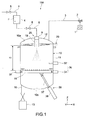
- Fig. 1 is a schematic view showing a freeze-drying apparatus according to an embodiment of the present invention.
- a freeze-drying apparatus 100 includes: a container 4 to store a raw material fluid F; a freezing chamber 10 being a vacuum chamber; a vacuum pump 1 for exhausting the freezing chamber 10; and an injection mechanism 25 to inject the raw material fluid F stored in the container 4 into the freezing chamber 10.
- the freezing chamber 10 has a cylindrical shape.
- the freezing chamber 10 includes: a main body 11; and a lid body 12 provided to be attachable to the main body 11.
- a top surface 10a is formed in the freezing chamber 10.
- the freezing chamber 10 includes a bottom surface 10b arranged to be opposed to the above-mentioned top surface 10a.
- a degree of vacuum within the freezing chamber 10 can be controlled in a range of from 0.1 to 500 Pa, for example.
- the raw material fluid F is one in a liquid form that is obtained by dissolving or dispersing fine powder of a raw material for a medical product, a food product, a cosmetic product, or the like in a solvent or a disperse media.
- the raw material fluid F includes one classified between a solid and liquid, that has a relatively large viscosity.
- an aqueous solution is used as a typical example of the raw material fluid F, that is, a case where the solvent is water.
- a gas-feeding tube 7 for feeding gas from a gas source (not shown) into the container 4. Nitrogen, argon, and other inert gas may be used as the gas.
- a raw material fluid-feeding tube 8 for feeding, due to a pressure of the gas fed from the gas-feeding tube 7, the raw material fluid F in the container 4 into the freezing chamber 10.
- On-off valves 5 and 6 there are respectively connected on-off valves 5 and 6.
- An exhaust tube 3 is connected between the vacuum pump 1 and the freezing chamber 10.
- the exhaust tube 3 is provided with an exhaust valve 2.
- the injection mechanism 25 includes at least a nozzle 9.
- the nozzle 9 is provided on an upper portion of the freezing chamber 10 and is connected to the raw material fluid-feeding tube 8.
- the freeze-drying apparatus 100 includes: a shelf 16 arranged in the freezing chamber 10; and a diffusion mechanism 30 to diffuse, by a vibration, the raw material received by the shelf 16. On the shelf 16, the frozen raw material of the raw material fluid F injected by the nozzle 9 is deposited.
- the diffusion mechanism 30 is constituted, for example, by a plurality of plunger-type vibration generators 31 and 32.
- a magnetic force or an air pressure is used for a power source for each of the vibration generators 31 and 32.
- Each of the vibration generators 31 and 32 is, for example, fixed to the freezing chamber 10 so that the plungers thereof abut against a peripheral portion of the shelf 16. In this manner, the shelf 16 is adapted to be vibrated.
- a tilt mechanism 35 to rotate the shelf 16 about a predetermined axis, for example, a rotational axis along the Y-axis direction of Fig. 1 , to thereby cause the shelf 16 to be tilted.
- the tilt mechanism 35 includes, for example, a rod 37 and a cylinder 36.
- the rod 37 is connected to a back surface of the shelf 16.
- the cylinder 36 is provided to be movable below the freezing chamber 10 so as to extend or retract the rod 37.
- the shelf 16 has a circular shape as seen in a plan view (seen in the Z-axis direction). However, the shelf 16 may have a rectangular shape.
- a rotational portion of the shelf 16 for example, an air bearing or a magnetic levitation system may be used. With this, it is possible to rotate the shelf 16 in a non-sliding manner.
- the vibration generators 31 operate when the shelf 16 is held in a horizontal state.
- the vibration generator 32 operates when the shelf 16 is tilted by the tilt mechanism 35.
- two vibration generators 31 are provided.
- One vibration generator 31 may be provided or three or more vibration generators 31 may be provided.
- a plurality of vibration generators 32 may be similarly provided.
- the shelf 16 is provided with a heating/cooling mechanism (not shown).
- a heating/cooling mechanism for example, there is used a system of circulating a liquid-phase medium in an inside of the shelf 16.
- a heating mechanism for the liquid-phase medium a resistive-heating-type heater such as a sheath heater is used.
- a cooling mechanism for the liquid-phase medium there is used a system of circulating the liquid-phase medium within a cooler which has been cooled with a coolant, to thereby performing a cooling.
- the resistive-heating-type heater such as the sheath heater may be used as the heating mechanism to directly heat the shelf 16. Otherwise, a Peltier device may be used as the cooling mechanism to directly cool the shelf 16.
- the freeze-drying apparatus 100 includes a cold trap 20.
- the cold trap 20 serves as a collection mechanism to collect a vapor, which is vaporized or sublimed from the raw material fluid F, in the freezing chamber 10.
- the cold trap 20 includes a tube through which a cooling medium flows.
- a cooling system in which the liquid-phase medium circulates through the tube, or a cooling system using a phase change of the coolant due to the circulation of the coolant.
- a cooling temperature is set to -60°C or less.
- the coolant-phase-change system the coolant providing a cooling temperature of -120°C or less is even used.
- a typical example of the liquid-phase medium includes silicone oil.
- the freeze-drying apparatus 100 does not have a structure in which the vacuum chamber and the cold trap are connected to each other via the vacuum exhaust tube as in the past.
- a flow velocity of the vapor is increased, and hence a phenomenon that the raw material is discharged to the outside of the vacuum chamber together with the vapor as in the past can be prevented.
- the collection rate of the raw material can be increased. Further, it becomes unnecessary to provide the baffle plate or the like for preventing the phenomenon in vicinity of the exhaust port of the vacuum chamber.
- Fig. 2 is a perspective view showing an example of a cold trap 20.
- Fig. 3(A) is a plan view of the cold trap 20 and
- Fig. 3(B) is a side view of the cold trap 20.
- the cold trap 20 is formed into a tube shape as described above.
- the cold trap 20 is constituted by two cooling tubes 21 and 22 arranged in an upper and lower direction.
- the cooling tubes 21 and 22 have a curved shape so as to provide predetermined spaces (gaps) 21a and 22a, respectively.
- the cooling tubes 21 and 22 are each turned back at a plurality of positions.
- Each of the cooling tubes 21 and 22 extends, as a whole, in a circular form as seen in the plan view.
- each of the cooling tubes 21 and 22 is formed to extend on the plane, and hence a larger collection area for the vapor in the freezing chamber 10 can be obtained. Further, due to the large collection area, no large pressure difference is generated in the freezing chamber 10.
- the raw material in the particle form after frozen hereinafter, referred to as frozen particles
- the cooling tubes 21 and 22 respectively include for the coolant, inlet portions 21b and 22b and outlet portions 21c and 22c, which are formed into a straight shape, for example.
- Fig. 4 is a perspective view showing a lid body 12 for the freezing chamber 10 in which the cold trap 20 is provided. As shown in Fig. 4 , the respective cooling tubes are provided in the lid body 12 in such a manner that the inlet portions 21b and 22b and the outlet portions 21c and 22c are projected to the outside of the freezing chamber 10.
- the respective cooling tubes are connected to a source (not shown) of the coolant in the outside of the freezing chamber 10.
- a worker removes the lid body 12.
- a maintenance for the cold trap 20 provided in the lid body 12 is also possible.
- a diameter r1 of the upper cooling tube 21 is set to be smaller than a diameter r2 of the lower cooling tube 22 so that the upper cooling tube 21 can be arranged above the space 22a (see Fig. 3(A) ) of the lower cooling tube 22.
- this configuration of the cold trap 20 it is possible to set the space to be the minimum or to eliminate the space as seen in the plan view. With this, the collection area for the vapor becomes further larger, and hence the collection rate is increased.
- each of the cooling tubes 21 and 22 there is provided an opening 23.
- the opening 23 and the nozzle 9 fixed to the lid body 12 are aligned to each other, and the nozzle 9 injects the raw material fluid F through the opening 23 substantially in a lower direction.
- a cover 19 is inserted in the opening 23.
- the cover 19 prevents the raw material fluid F injected by the nozzle 9 from splashing toward the cooling tubes 21 and 22.
- the cover 19 is not indispensable.
- the shelf 16 is arranged at a height position closer to the bottom surface 10b than the top surface 10a of the freezing chamber 10. Further, the cold trap 20 is arranged at a height position closer to the top surface 10a as compared to the shelf 16 arranged at the above-mentioned height position.
- a height h1 is, for example, 1 m or more, the height h1 extending from a reception surface of the shelf 16 (upper surface of shelf 16), on which the raw material is received, to the cold trap 20. However, depending on process conditions, the height h1 may be smaller than 1 m.
- the process conditions includes, for example, the kind of the raw material, the flow rate of the raw material fluid F flowing out of the nozzle 9, the degree of vacuum within the freezing chamber 10, and the thermal process temperature for the shelf 16.
- a collection container 13 to collect the raw material after freeze-dried is connected to a bottom portion of the freezing chamber 10 through a collection channel 15.
- a control portion (not shown) controls the respective operations of the exhaust valve 2, the vacuum pump 1, the on-off valves 5 and 6, the rotation of the shelf 16, the vibration of the shelf 16, and the like.
- the pressure within the freezing chamber 10 is lowered so that the pressure within the freezing chamber 10 is maintained in a predetermined degree of vacuum.
- the shelf 16 is held in the horizontal state as shown in Fig. 1 .
- the raw material fluid F is fed to the nozzle 9 due to the gas pressure. Then, from the nozzle 9 into the freezing chamber 10, the raw material fluid F is injected. In some cases, the raw material fluid F may be previously cooled before fed into the freezing chamber 10.
- the raw material fluid F injected from the nozzle 9 is one in a liquid form containing moisture of the solvent before the middle of the falling of raw material fluid F. After the middle of the falling of raw material fluid F, the moisture is vaporized or sublimed. Due to an endothermic reaction at the above-mentioned time, the raw material is frozen. The raw material is frozen, that is, the vapor is separated from the raw material, and hence the raw material is dried.
- the raw material is frozen means a state in which the raw material is deposited on the shelf 16 and the deposited raw material is frozen in such a degree that the deposited raw material does not adhere to the shelf 16. In this case, an entire or a part of at least a surface of the raw material may be frozen.
- the vapor is collected by the cold trap 20.
- the shelf 16 is cooled by the cooling mechanism. With this, the freezing action of the particles of the raw material is promoted, and hence the productivity of the particles is increased.
- the temperature of the reception surface of the shelf 16, which is lowered by the cooling mechanism is, for example, set to -60 to 0°C (0°C, -15°C, -20°C, -22.5°C, -25°C, -30°C, -40°C, -50°C, -60°C, or another temperature).
- the shelf 16 is vibrated in a horizontal direction due to the actuation of the vibration generator 31. With this, the frozen particles deposited on the shelf 16 are evenly diffused on the shelf 16 in such a manner that a deposition thickness thereof becomes smaller or a single layer thereof is formed. With this, a freezing efficiency and a drying efficiency of individual particles are promoted.
- the heating mechanism heats the shelf 16. With this, the drying action of the frozen particles is promoted, and hence the productivity of the particles is promoted.
- the drying process by the heating mechanism is referred to as a heat-drying in order to discriminate this drying process from the drying due to the freezing.
- the temperature of the deposition surface of the shelf 16, which is lowered by the heating mechanism is, for example, set to 20 to 50°C (20, 40, 50°C, or another temperature).
- the shelf 16 When the heat-drying of the frozen particles is terminated, the shelf 16 is tilted by the tilt mechanism 35 as shown in Fig. 5 . Further, due to the actuation of the vibration generator 32, the shelf 16 is vibrated. With this, dried particles (particles after heat-drying is terminated) are collected through the collection channel 15 into the collection container 13 due to its own weight and an acceleration thereof due to the vibration. Although when the shelf 16 is held in the tilted state, a vibration direction of the vibration generator 32 is a substantial horizontal direction, the vibration direction of the vibration generator 32 may be the tilted direction or another direction.
- the raw material of the raw material fluid F injected from the nozzle 9 is vaporized or sublimed in the middle of the falling of the raw material fluid F.
- the height position where the raw material is frozen within the freezing chamber 10 and the height position of the cold trap 20 are away from each other in some degree.
- the raw material can be prevented from being attracted toward the cold trap 20 together with the vapor.
- Fig. 6 is a schematic view showing a freeze-drying apparatus according to another embodiment of the present invention.
- the descriptions of members, functions thereof, and the like included in the freeze-drying apparatus 200 which are similar to those according to the embodiment shown in Fig. 1 and the like will be simplified or omitted, and different points will be mainly described.
- the nozzle 9 is arranged in a side surface 10d of the freezing chamber 10 being the vacuum chamber.
- the raw material fluid F is injected substantially in the horizontal direction.
- the height position of the nozzle 9 may be lower than the position shown in Fig. 6 .
- the nozzle 9 may be arranged in a height position in the middle of the distance between the cold trap 20 and the upper surface of the shelf 16, or at a height position closer to the shelf 16 as compared to the above-mentioned height position in the middle.
- Fig. 7 is a schematic view showing a freeze-drying apparatus according to still another embodiment of the present invention.
- the freeze-drying apparatus 300 shown in Fig. 7 includes, in the side surface 10d of the freezing chamber 10, a raw material fluid-feeding tube 28 extending from the outside to the inside of the freezing chamber 10. To an end portion of the raw material fluid-feeding tube 28, which extends in the freezing chamber 10, the nozzle 9 is connected. The nozzle 9 injects the raw material fluid F substantially in an upper direction.
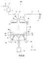
- Fig. 8 is a schematic view showing a freeze-drying apparatus according to still another embodiment of the present invention.
- the shelf 16 provided in the freezing chamber 10 of the freeze-drying apparatus 400 is adapted to be split into a first shelf member 16a and a second shelf member 16b, for example, about the center of the shelf 16 by two tilt mechanisms 35, as indicated by the two-dot chain lines of Fig. 8 . It is needless to say that the shelf 16 may be split into three or more parts by three or more tilt mechanisms 35.
- the two split shelves 16 (16a and 16b) in the tilted state receive a vibration from the vibration generators 32 and 32, respectively.
- the collection channel 15 provided in the center of the bottom surface 10b of the freezing chamber 10 the particles subjected to the heat-drying (and/or frozen) are collected into the collection container 13.
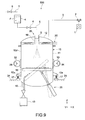
- Fig. 9 is a schematic view showing a freeze-drying apparatus according to still another embodiment.
- a plurality of vibration generators 33 are provided as vibration mechanisms to vibrate the freezing chamber 10.
- the vibration generators 33 are vibration motors including counter weights 34, for example.
- Two vibration generators 33 are respectively provided at positions away from each other by 180° as seen in the plan view, for example. That is, the vibration generators 33 are provided to be opposed to each other.
- the freezing chamber 10 is installed in a floor 24 through the coil springs 17. With this, the freezing chamber 10 can be vibrated.
- phases of the vibrations of both of the vibration generators 33 are controlled. Otherwise, the phases of the vibrations of both of the vibration generators 33 may be controlled in order to cause the freezing chamber 10 to be vibrated substantially in the horizontal direction.
- Fig. 10 is a schematic view showing a freeze-drying apparatus according to still another embodiment of the present invention.
- the freeze-drying apparatus 800 is an apparatus according to an embodiment in which the above-mentioned freeze-drying apparatuses 400 and 500 are combined to each other. That is, the vibration generators 33 to vibrate the freezing chamber 10 are provided as the diffusion mechanisms, and the shelf 16 can be split into a plurality of shelf members (16a and 16b).
- Fig. 11 is a schematic view showing a freeze-drying apparatus according to still another embodiment of the present invention.
- the vacuum chamber 60 includes: a freezing chamber 40; and a drying chamber 50 long in one direction (X-axis direction).
- a freezing chamber 40 In the lower portion of the freezing chamber 40, there is provided an opening 40a.
- the opening 40a is communicated through a bellows 26 to an opening 50a provided in an upper portion of the drying chamber 50. In this manner, the freezing chamber 40 and the drying chamber 50 are connected to each other in a hermetically sealed manner.
- the nozzle 9 injects the raw material fluid F fed from the container 4 storing the raw material fluid F.
- the vacuum pump 1 is connected through the exhaust tube 3 and the exhaust valve 2 to the drying chamber 50.
- a shelf 29 constituting a transport channel extending in a predetermined direction. Further, to an opposite side to a side on which the opening 50a of the drying chamber 50 is provided, the collection container 13 for the particles is connected.
- the shelf 29 receives the frozen particles falling from the freezing chamber 40 through the bellows 26, and causes the received frozen particles to be transported to the predetermined direction by a vibration.
- the shelf 29 may be configured to be capable of being thermally processed by the heating mechanism and the cooling mechanism.
- the vibration generators 33 to vibrate the drying chamber 50 are fixed.
- the vibration motors including the counter weights 34 shown in Fig. 9 and Fig. 10 are used, for example.
- the number of the vibration generators 33 is not limited.
- the coil springs 17 are provided through spring-mounting portions 50e on the outer surface of the drying chamber 50, and the drying chamber 50 is installed in the floor 24 through the coil springs 17. With this, the drying chamber 50 can be vibrated.
- a mounting angle of the vibration generators 33 with respect to the drying chamber 50 can be changed obliquely with respect to the horizontal direction (X-axis direction) as indicated by the two-dot chain lines, and hence it is possible to generate a vibration in an oblique direction in the X-Z plane.
- the drying chamber 50 is vibrated in the oblique direction, and hence the frozen particles are transported to the predetermined direction.
- the mounting angle of the vibration generators 33 with respect to the drying chamber 50 can be changed, and hence a transport speed for the frozen particles can be changed under control.
- the mounting angle of the vibration generators 33 with respect to the drying chamber 50 may be manually changed by a worker, or may be automatically changed through a mechanism to control the above-mentioned angle.
- the vibration generators 33 are capable of diffusing the frozen particles deposited on the shelf 29 by its own vibration.
- a cold trap 120 is connected to the drying chamber 50.
- the vapor vaporized or sublimed mainly from the raw material fluid F injected in the freezing chamber 40 is collected by the cold trap 120 within the drying chamber 50.
- the general shape of the cold trap 120 as seen in the plan view is designed depending on the shape of the top surface 10a of the drying chamber 50, for example. Any shape is possible as long as the area of the cold trap 120 as seen in the Z-axis direction becomes larger as much as possible. Further, the cold trap 120 may have the tube shape as described above, and a plate-shaped cold trap 120 and a cold trap 120 having any other shape are possible.
- a height h2 of the freezing chamber 40 is for example 1.5 m or more, the height h2 is not limited to thereto. Further, although a height h3 extending from the surface of the shelf 29 to the cold trap 120 is about 1 m, the height h3 is also not limited to this value.
- freeze-drying apparatus 600 thus configured will be described.
- the frozen particles which are injected and fallen from the nozzle 9 to be frozen, are deposited on the shelf 29 of the drying chamber 50 through the bellows 26.
- the shelf 29 is provided with the cooling mechanism, then the shelf 29 is cooled, to thereby promote the freezing action.
- the vibration generator 33 vibrates the drying chamber 50 with a result that the frozen particles deposited on the shelf 29 are diffused.
- a timing when the vibration of the drying chamber 50 is started is typically set to be before the injection of the raw material fluid, the above-mentioned timing may be set to be during or after the injection of the raw material fluid.
- the angle of the vibration generators 33 is changed with a result in which the frozen particles are transported toward the collection container 13. Otherwise, both of the diffusion and the transport of the particles may be performed simultaneously.
- the vibration of the drying chamber 50 is absorbed by the bellows 26, and hence this vibration is not transmitted to the freezing chamber 40. Otherwise, even if the above-mentioned vibration is transmitted to the freezing chamber 40, this vibration is attenuated in such a degree that the freezing chamber 40 is not influenced by this vibration.
- the shelf 29 is provided with the heating mechanism, then the shelf 29 is heated, to thereby promote the drying action of the frozen particles on the shelf 29 by the heating.
- the particles transported toward the collection container 13 are fallen and collected into the collection container 13.
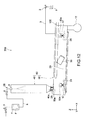
- Fig. 12 is a schematic view showing a freeze-drying apparatus according to still another embodiment of the present invention.
- the freeze-drying apparatus 700 is different from the freeze-drying apparatus 600 shown in Fig. 11 in that a longitudinal direction of the drying chamber 50 is tilted with respect to the horizontal direction (X-axis direction).
- a longitudinal direction of the drying chamber 50 is tilted with respect to the horizontal direction (X-axis direction).
- the vibration generators 33 may be fixed in the tilted state with respect to the shelf 29 of the drying chamber 50 as shown in Fig. 12 , to thereby generate the vibrational component in the oblique direction with respect to the shelf 29.
- both of the diffusion and the transport of the particles are performed simultaneously.
- Embodiments according to the present invention are not limited to the above-mentioned embodiments, and other various embodiments are conceivable.
- the drying chamber 50 may not vibrate and the shelf may vibrate in order to at least diffuse the frozen particles.
Landscapes
- Engineering & Computer Science (AREA)
- Life Sciences & Earth Sciences (AREA)
- Health & Medical Sciences (AREA)
- General Engineering & Computer Science (AREA)
- Mechanical Engineering (AREA)
- Molecular Biology (AREA)
- Zoology (AREA)
- Polymers & Plastics (AREA)
- Food Science & Technology (AREA)
- Chemical & Material Sciences (AREA)
- Wood Science & Technology (AREA)
- Drying Of Solid Materials (AREA)
- Freezing, Cooling And Drying Of Foods (AREA)
Abstract
Description
- The present invention relates to an injection-type freeze-drying apparatus and a freeze-drying method, which is capable of injecting a raw material for a medical product, a food product, a cosmetic product, or other chemicals in a vacuum chamber, to thereby freeze-dry the raw material.
- In an injection-type freeze-drying apparatus, a raw material fluid is injected in a vacuum chamber, the raw material fluid being obtained by dissolving or dispersing a raw material for a medical product, a food product, a cosmetic product, or the like in a solvent or a disperse medium. In the above-mentioned injection process, the solvent takes heat from the raw material due to latent heat of vaporization thereof, and thus the raw material is frozen and dried. At this time, the raw material is formed into fine particles, and then is collected in a collector provided in a lower portion of the vacuum chamber. Further, in order to promote the above-mentioned drying action, the raw material is heated by a resistive-heating-type heater provided to the collector. It should be noted that in order to efficiently freeze the raw material within the vacuum chamber, the raw material is previously cooled before the raw material is injected in the vacuum chamber (for example, see Patent Document 1).
- An apparatus (30) disclosed in
Patent Document 2 transports frozen fine particles (F), which have been discharged from a vacuum freezing column (11), by use of a conveyor belt (22) provided in a drying chamber (21). It is proposed that in place of the conveyor belt (22), a vibrating conveyor may be used (for example, see Patent Document 2). - It should be noted that in the general freeze-drying method in the past, the raw material is frozen in advance before the raw material is received in the vacuum chamber, while in the injection-type freeze-drying method, the raw material is injected, formed into particles, and frozen by itself in the vacuum chamber. In view of the above-mentioned point, those methods are different from each other.
-
- Patent Document 1: Japanese Patent Application Laid-open No.
2004-232883 Fig. 1 ) - Patent Document 2: Japanese Patent Application Laid-open No.
2006-177640 Fig. 6 ) - By the way, for example, in the drying chamber (21) of the apparatus (30) disclosed in the above-mentioned
Patent Document 2, a resistive-heating-type heater (25) is provided, and thus the drying process for the frozen fine particles (F) is promoted. Here, it is conceivable that the frozen fine particles (F) are dried more efficiently, and hence a quality of the particle products can be enhanced. - In view of the above-mentioned circumstances, it is an object of the present invention to provide a freeze-drying apparatus and a freeze-drying method, which are capable of increasing a drying efficiency of frozen particles.
- In order to achieve the above-mentioned object, a freeze-drying apparatus according to an embodiment of the present invention includes a vacuum chamber, an injection mechanism, a shelf, and a diffusion mechanism.
The vacuum chamber is capable of being exhausted. The injection mechanism injects a raw material fluid including a raw material into the vacuum chamber exhausted.
The shelf receives the raw material frozen when the raw material fluid is injected.
The diffusion mechanism at least diffuses the raw material on the shelf by a vibration, the raw material being received on the shelf. - A freeze-drying method according to an embodiment of the present invention includes injecting a raw material fluid including a raw material into a vacuum chamber exhausted.
The raw material is at least diffused on a shelf by a vibration, the raw material being frozen when the raw material fluid is injected and being received by the shelf. -
- [
Fig. 1 ] A schematic view showing a freeze-drying apparatus according to an embodiment of the present invention. - [
Fig. 2 ] A perspective view showing an example of a cold trap. - [
Figs. 3] Fig. 3(A) is a plan view of the cold trap andFig. 3(B) is a side view of the cold trap. - [
Fig. 4 ] A perspective view showing a lid body for a freezing chamber in which the cold trap is provided. - [
Fig. 5 ] A view showing a state in which particles are being collected into a collecting container in the freeze-drying apparatus shown inFig. 1 . - [
Fig. 6 ] A schematic view showing a freeze-drying apparatus according to another embodiment of the present invention, in a mode of injecting a raw material fluid in a horizontal direction. - [
Fig. 7 ] A schematic view showing a freeze-drying apparatus according to still another embodiment of the present invention, in a mode of injecting a raw material fluid in an upper direction. - [
Fig. 8 ] A schematic view showing a freeze-drying apparatus according to still another embodiment of the present invention, in a mode in which a shelf is to be split. - [
Fig. 9 ] A schematic view showing a freeze-drying apparatus according to still another embodiment of the present invention, in a mode in which a freezing chamber vibrates. - [
Fig. 10 ] A schematic view showing a freeze-drying apparatus according to still another embodiment of the present invention, in a mode in which a freezing chamber vibrates and a shelf is to be split into a plurality of shelf members. - [
Fig. 11 ] A schematic view showing a freeze-drying apparatus according to still another embodiment of the present invention, in which a vacuum chamber is divided into a freezing chamber and a drying chamber. - [
Fig. 12 ] A schematic view showing a freeze-drying apparatus according to still another embodiment of the present invention, in a mode in which a shelf of a drying chamber is tilted. - A freeze-drying apparatus includes a vacuum chamber, an injection mechanism, a shelf, and a diffusion mechanism. The vacuum chamber is capable of being exhausted. The injection mechanism injects a raw material fluid including a raw material into the vacuum chamber exhausted. The shelf receives the raw material frozen when the raw material fluid is injected. The diffusion mechanism at least diffuses the raw material on the shelf by a vibration, the raw material being received on the shelf.
- The raw material on the shelf is diffused by the vibration, and hence it is possible to efficiently dry the frozen particles on the shelf.
- The diffusion mechanism may include a vibration generator to vibrate the shelf.
- The vibration generator may vibrate the shelf in a horizontal direction or an upper and lower direction. It is sufficient for the horizontal direction to be a substantial horizontal direction in light of the spirit of the present invention. Similarly, it is sufficient for the upper and lower direction to be a substantial upper and lower direction in light of the spirit of the present invention.
- The freeze-drying apparatus may further include a tilt mechanism to tilt the shelf in order to collect the raw material on the shelf. In a state in which the raw material on the shelf is diffused by the diffusion mechanism, the tilt mechanism is capable of tilting the shelf. Thus, it is possible to increase the collection rate of the raw material on the shelf.
- The diffusion mechanism may include a first vibration generator to vibrate the shelf when the shelf is held in a horizontal state, and a second vibration generator to vibrate the shelf when the shelf is held in a tilted state.
- The shelf may include at least a first shelf member and a second shelf member. In this case, the tilt mechanism may include a first tilt mechanism to tilt the first shelf member, and a second tilt mechanism to tilt the second shelf member. Thus, the first shelf member and the second shelf member may be tilted by the first tilt mechanism and the second tilt mechanism, to thereby split the shelf into the first shelf member and the second shelf member, respectively.
- The diffusion mechanism may include a first vibration generator to vibrate the shelf when the first shelf member and the second shelf member are held in a horizontal state, and a second vibration generator to vibrate the shelf when the first shelf member and the second shelf member are held in a tilted state. In this case, one first vibration generator may be provided, or two first vibration generators may be provided so that the first shelf member and the second shelf member can be each vibrated. The same applies to the second vibration generator.
- The vacuum chamber may include a freezing chamber within which the shelf is arranged, and the diffusion mechanism may include a vibration generator to vibrate the freezing chamber. In the case where the shelf is arranged within the freezing chamber as described above, the freezing chamber may be vibrated by the vibration generator, to thereby vibrate the shelf.
- The vacuum chamber may include a freezing chamber into which the raw material fluid is injected, and a drying chamber within which the shelf is arranged, the drying chamber being connected to the freezing chamber in a hermetically sealed manner. In this case, the diffusion mechanism may transport the frozen raw material by the vibration. In this case, the diffusion mechanism may include a vibration generator to vibrate the shelf, or the diffusion mechanism may include a vibration generator to vibrate the drying chamber. Otherwise, the diffusion mechanism may vibrate the shelf.
- The vibration generator may include a vibration motor mounted to the drying chamber in a changeable mounting angle in order to control a transport speed for the raw material. Also in a case where the vibration generator vibrates the shelf itself, a vibration motor similar to the above-mentioned vibration motor may be used.
- The freeze-drying apparatus may further include a thermal process mechanism to perform at least one of a heating and a cooling of the shelf. The shelf is cooled, and hence the freezing action of the raw material is promoted, or the shelf is heated, and hence the drying action of the particles after frozen is promoted. With this, a productivity of dried particles (particles after the frozen particles are dried by the thermal process mechanism) is promoted.
- A freeze-drying method includes injecting a raw material fluid including a raw material into a vacuum chamber exhausted. The raw material is at least diffused on a shelf by a vibration, the raw material being frozen when the raw material fluid is injected and being received by the shelf. The raw material on the shelf is diffused by the vibration, and hence it is possible to efficiently dry the frozen particles on the shelf.
- Hereinafter, embodiments of the present invention will be described with reference to the drawings.
-
Fig. 1 is a schematic view showing a freeze-drying apparatus according to an embodiment of the present invention. - A freeze-
drying apparatus 100 includes: acontainer 4 to store a raw material fluid F; a freezingchamber 10 being a vacuum chamber; avacuum pump 1 for exhausting the freezingchamber 10; and aninjection mechanism 25 to inject the raw material fluid F stored in thecontainer 4 into the freezingchamber 10. - Typically, the freezing
chamber 10 has a cylindrical shape. The freezingchamber 10 includes: amain body 11; and alid body 12 provided to be attachable to themain body 11. When thelid body 12 is attached to themain body 11, atop surface 10a is formed in the freezingchamber 10. Further, the freezingchamber 10 includes abottom surface 10b arranged to be opposed to the above-mentionedtop surface 10a. A degree of vacuum within the freezingchamber 10 can be controlled in a range of from 0.1 to 500 Pa, for example. - The raw material fluid F is one in a liquid form that is obtained by dissolving or dispersing fine powder of a raw material for a medical product, a food product, a cosmetic product, or the like in a solvent or a disperse media. Here, the raw material fluid F includes one classified between a solid and liquid, that has a relatively large viscosity. In the following description, the description will be made of a case where an aqueous solution is used as a typical example of the raw material fluid F, that is, a case where the solvent is water.
- To the
container 4, there is connected a gas-feedingtube 7 for feeding gas from a gas source (not shown) into thecontainer 4. Nitrogen, argon, and other inert gas may be used as the gas. To thecontainer 4, there is connected a raw material fluid-feedingtube 8 for feeding, due to a pressure of the gas fed from the gas-feedingtube 7, the raw material fluid F in thecontainer 4 into the freezingchamber 10. To the gas-feedingtube 7 and the raw material fluid-feedingtube 8, there are respectively connected on-offvalves - An
exhaust tube 3 is connected between thevacuum pump 1 and the freezingchamber 10. Theexhaust tube 3 is provided with anexhaust valve 2. - The
injection mechanism 25 includes at least anozzle 9. For example, thenozzle 9 is provided on an upper portion of the freezingchamber 10 and is connected to the raw material fluid-feedingtube 8. - The freeze-
drying apparatus 100 includes: ashelf 16 arranged in the freezingchamber 10; and adiffusion mechanism 30 to diffuse, by a vibration, the raw material received by theshelf 16. On theshelf 16, the frozen raw material of the raw material fluid F injected by thenozzle 9 is deposited. - The
diffusion mechanism 30 is constituted, for example, by a plurality of plunger-type vibration generators vibration generators vibration generators chamber 10 so that the plungers thereof abut against a peripheral portion of theshelf 16. In this manner, theshelf 16 is adapted to be vibrated. - To the
shelf 16, there is connected atilt mechanism 35 to rotate theshelf 16 about a predetermined axis, for example, a rotational axis along the Y-axis direction ofFig. 1 , to thereby cause theshelf 16 to be tilted. Thetilt mechanism 35 includes, for example, arod 37 and acylinder 36. Therod 37 is connected to a back surface of theshelf 16. Thecylinder 36 is provided to be movable below the freezingchamber 10 so as to extend or retract therod 37. Typically, theshelf 16 has a circular shape as seen in a plan view (seen in the Z-axis direction). However, theshelf 16 may have a rectangular shape. - It should be noted that although not shown, in a rotational portion of the
shelf 16, for example, an air bearing or a magnetic levitation system may be used. With this, it is possible to rotate theshelf 16 in a non-sliding manner. - The
vibration generators 31 operate when theshelf 16 is held in a horizontal state. Thevibration generator 32 operates when theshelf 16 is tilted by thetilt mechanism 35. For example, twovibration generators 31 are provided. Onevibration generator 31 may be provided or three ormore vibration generators 31 may be provided. A plurality ofvibration generators 32 may be similarly provided. - The
shelf 16 is provided with a heating/cooling mechanism (not shown). For the heating/cooling mechanism, for example, there is used a system of circulating a liquid-phase medium in an inside of theshelf 16. As a heating mechanism for the liquid-phase medium, a resistive-heating-type heater such as a sheath heater is used. Further, a cooling mechanism for the liquid-phase medium, there is used a system of circulating the liquid-phase medium within a cooler which has been cooled with a coolant, to thereby performing a cooling. Further, the resistive-heating-type heater such as the sheath heater may be used as the heating mechanism to directly heat theshelf 16. Otherwise, a Peltier device may be used as the cooling mechanism to directly cool theshelf 16. - The freeze-
drying apparatus 100 includes acold trap 20. Thecold trap 20 serves as a collection mechanism to collect a vapor, which is vaporized or sublimed from the raw material fluid F, in the freezingchamber 10. - Typically, the
cold trap 20 includes a tube through which a cooling medium flows. In thecold trap 20, for example, there is used a cooling system in which the liquid-phase medium circulates through the tube, or a cooling system using a phase change of the coolant due to the circulation of the coolant. Typically, in the liquid-phase circulation cooling system, a cooling temperature is set to -60°C or less. In the coolant-phase-change system, the coolant providing a cooling temperature of -120°C or less is even used. A typical example of the liquid-phase medium includes silicone oil. - As described above, the freeze-
drying apparatus 100 does not have a structure in which the vacuum chamber and the cold trap are connected to each other via the vacuum exhaust tube as in the past. Thus, a flow velocity of the vapor is increased, and hence a phenomenon that the raw material is discharged to the outside of the vacuum chamber together with the vapor as in the past can be prevented. With this, the collection rate of the raw material can be increased. Further, it becomes unnecessary to provide the baffle plate or the like for preventing the phenomenon in vicinity of the exhaust port of the vacuum chamber. -
Fig. 2 is a perspective view showing an example of acold trap 20.Fig. 3(A) is a plan view of thecold trap 20 andFig. 3(B) is a side view of thecold trap 20. - The
cold trap 20 is formed into a tube shape as described above. For example, thecold trap 20 is constituted by twocooling tubes cooling tubes cooling tubes cooling tubes cooling tubes chamber 10 can be obtained. Further, due to the large collection area, no large pressure difference is generated in the freezingchamber 10. Thus, the raw material in the particle form after frozen (hereinafter, referred to as frozen particles) can be prevented from being attracted toward thecold trap 20. - The
cooling tubes inlet portions outlet portions Fig. 4 is a perspective view showing alid body 12 for the freezingchamber 10 in which thecold trap 20 is provided. As shown inFig. 4 , the respective cooling tubes are provided in thelid body 12 in such a manner that theinlet portions outlet portions chamber 10. - For example, during a maintenance for the freezing
chamber 10, a worker removes thelid body 12. Thus, during the above-mentioned maintenance, a maintenance for thecold trap 20 provided in thelid body 12 is also possible. - As shown in
Fig. 3(B) , for example, a diameter r1 of theupper cooling tube 21 is set to be smaller than a diameter r2 of thelower cooling tube 22 so that theupper cooling tube 21 can be arranged above thespace 22a (seeFig. 3(A) ) of thelower cooling tube 22. With this configuration of thecold trap 20, it is possible to set the space to be the minimum or to eliminate the space as seen in the plan view. With this, the collection area for the vapor becomes further larger, and hence the collection rate is increased. - In a center of each of the
cooling tubes opening 23. Theopening 23 and thenozzle 9 fixed to thelid body 12 are aligned to each other, and thenozzle 9 injects the raw material fluid F through theopening 23 substantially in a lower direction. As shown inFig. 1 , acover 19 is inserted in theopening 23. Thecover 19 prevents the raw material fluid F injected by thenozzle 9 from splashing toward thecooling tubes cover 19 is not indispensable. - The
shelf 16 is arranged at a height position closer to thebottom surface 10b than thetop surface 10a of the freezingchamber 10. Further, thecold trap 20 is arranged at a height position closer to thetop surface 10a as compared to theshelf 16 arranged at the above-mentioned height position. A height h1 is, for example, 1 m or more, the height h1 extending from a reception surface of the shelf 16 (upper surface of shelf 16), on which the raw material is received, to thecold trap 20. However, depending on process conditions, the height h1 may be smaller than 1 m. The process conditions includes, for example, the kind of the raw material, the flow rate of the raw material fluid F flowing out of thenozzle 9, the degree of vacuum within the freezingchamber 10, and the thermal process temperature for theshelf 16. - A
collection container 13 to collect the raw material after freeze-dried is connected to a bottom portion of the freezingchamber 10 through acollection channel 15. - A control portion (not shown) controls the respective operations of the
exhaust valve 2, thevacuum pump 1, the on-offvalves shelf 16, the vibration of theshelf 16, and the like. - The operation of the freeze-
drying apparatus 100 thus configured will be described. - When the
exhaust valve 2 is opened and thevacuum pump 1 is actuated, the pressure within the freezingchamber 10 is lowered so that the pressure within the freezingchamber 10 is maintained in a predetermined degree of vacuum. Theshelf 16 is held in the horizontal state as shown inFig. 1 . - When the on-off
valves nozzle 9 due to the gas pressure. Then, from thenozzle 9 into the freezingchamber 10, the raw material fluid F is injected. In some cases, the raw material fluid F may be previously cooled before fed into the freezingchamber 10. The raw material fluid F injected from thenozzle 9 is one in a liquid form containing moisture of the solvent before the middle of the falling of raw material fluid F. After the middle of the falling of raw material fluid F, the moisture is vaporized or sublimed. Due to an endothermic reaction at the above-mentioned time, the raw material is frozen. The raw material is frozen, that is, the vapor is separated from the raw material, and hence the raw material is dried. - "The raw material is frozen" means a state in which the raw material is deposited on the
shelf 16 and the deposited raw material is frozen in such a degree that the deposited raw material does not adhere to theshelf 16. In this case, an entire or a part of at least a surface of the raw material may be frozen. - At least during the injection of the raw material fluid F, the vapor is collected by the
cold trap 20. - During the injection of the raw material fluid F, the
shelf 16 is cooled by the cooling mechanism. With this, the freezing action of the particles of the raw material is promoted, and hence the productivity of the particles is increased. The temperature of the reception surface of theshelf 16, which is lowered by the cooling mechanism, is, for example, set to -60 to 0°C (0°C, -15°C, -20°C, -22.5°C, -25°C, -30°C, -40°C, -50°C, -60°C, or another temperature). - Further, during the injection of the raw material fluid F, after the injection of the raw material fluid F, or for a time period covering the start to the termination of the injection of the raw material fluid F, the
shelf 16 is vibrated in a horizontal direction due to the actuation of thevibration generator 31. With this, the frozen particles deposited on theshelf 16 are evenly diffused on theshelf 16 in such a manner that a deposition thickness thereof becomes smaller or a single layer thereof is formed. With this, a freezing efficiency and a drying efficiency of individual particles are promoted. - When the injection of the raw material fluid F is terminated, the heating mechanism heats the
shelf 16. With this, the drying action of the frozen particles is promoted, and hence the productivity of the particles is promoted. In the following description, the drying process by the heating mechanism is referred to as a heat-drying in order to discriminate this drying process from the drying due to the freezing. The temperature of the deposition surface of theshelf 16, which is lowered by the heating mechanism, is, for example, set to 20 to 50°C (20, 40, 50°C, or another temperature). - When the heat-drying of the frozen particles is terminated, the
shelf 16 is tilted by thetilt mechanism 35 as shown inFig. 5 . Further, due to the actuation of thevibration generator 32, theshelf 16 is vibrated. With this, dried particles (particles after heat-drying is terminated) are collected through thecollection channel 15 into thecollection container 13 due to its own weight and an acceleration thereof due to the vibration. Although when theshelf 16 is held in the tilted state, a vibration direction of thevibration generator 32 is a substantial horizontal direction, the vibration direction of thevibration generator 32 may be the tilted direction or another direction. - In this embodiment, the raw material of the raw material fluid F injected from the
nozzle 9 is vaporized or sublimed in the middle of the falling of the raw material fluid F. As described above, even in a configuration in which the raw material fluid F is injected from thenozzle 9 through theopenings 23 provided in thecooling tubes chamber 10, and the height position of thecold trap 20 are away from each other in some degree. Thus, the raw material can be prevented from being attracted toward thecold trap 20 together with the vapor. -
Fig. 6 is a schematic view showing a freeze-drying apparatus according to another embodiment of the present invention. In the following description, the descriptions of members, functions thereof, and the like included in the freeze-drying apparatus 200, which are similar to those according to the embodiment shown inFig. 1 and the like will be simplified or omitted, and different points will be mainly described. - In the freeze-
drying apparatus 200 shown inFig. 6 , thenozzle 9 is arranged in aside surface 10d of the freezingchamber 10 being the vacuum chamber. Thus, the raw material fluid F is injected substantially in the horizontal direction. - It should be noted that the height position of the
nozzle 9 may be lower than the position shown inFig. 6 . For example, thenozzle 9 may be arranged in a height position in the middle of the distance between thecold trap 20 and the upper surface of theshelf 16, or at a height position closer to theshelf 16 as compared to the above-mentioned height position in the middle. -
Fig. 7 is a schematic view showing a freeze-drying apparatus according to still another embodiment of the present invention. - The freeze-
drying apparatus 300 shown inFig. 7 includes, in theside surface 10d of the freezingchamber 10, a raw material fluid-feedingtube 28 extending from the outside to the inside of the freezingchamber 10. To an end portion of the raw material fluid-feedingtube 28, which extends in the freezingchamber 10, thenozzle 9 is connected. Thenozzle 9 injects the raw material fluid F substantially in an upper direction. -
Fig. 8 is a schematic view showing a freeze-drying apparatus according to still another embodiment of the present invention. - The
shelf 16 provided in the freezingchamber 10 of the freeze-drying apparatus 400 is adapted to be split into afirst shelf member 16a and asecond shelf member 16b, for example, about the center of theshelf 16 by twotilt mechanisms 35, as indicated by the two-dot chain lines ofFig. 8 . It is needless to say that theshelf 16 may be split into three or more parts by three ormore tilt mechanisms 35. - The two split shelves 16 (16a and 16b) in the tilted state receive a vibration from the
vibration generators collection channel 15 provided in the center of thebottom surface 10b of the freezingchamber 10, the particles subjected to the heat-drying (and/or frozen) are collected into thecollection container 13. -
Fig. 9 is a schematic view showing a freeze-drying apparatus according to still another embodiment. - In the side surface of the freezing
chamber 10 of the freeze-drying apparatus 500, a plurality ofvibration generators 33 are provided as vibration mechanisms to vibrate the freezingchamber 10. Thevibration generators 33 are vibration motors includingcounter weights 34, for example. Twovibration generators 33 are respectively provided at positions away from each other by 180° as seen in the plan view, for example. That is, thevibration generators 33 are provided to be opposed to each other. On theouter surface 10d of the freezingchamber 10, there are providedcoil springs 17 through spring-mountingportions 10e. The freezingchamber 10 is installed in afloor 24 through the coil springs 17. With this, the freezingchamber 10 can be vibrated. - In order to cause the freezing
chamber 10 to be vibrated substantially in the upper and lower direction, phases of the vibrations of both of thevibration generators 33 are controlled. Otherwise, the phases of the vibrations of both of thevibration generators 33 may be controlled in order to cause the freezingchamber 10 to be vibrated substantially in the horizontal direction. -
Fig. 10 is a schematic view showing a freeze-drying apparatus according to still another embodiment of the present invention. - The freeze-
drying apparatus 800 is an apparatus according to an embodiment in which the above-mentioned freeze-drying apparatuses vibration generators 33 to vibrate the freezingchamber 10 are provided as the diffusion mechanisms, and theshelf 16 can be split into a plurality of shelf members (16a and 16b). -
Fig. 11 is a schematic view showing a freeze-drying apparatus according to still another embodiment of the present invention. - In the freeze-
drying apparatus 600, thevacuum chamber 60 includes: a freezingchamber 40; and a dryingchamber 50 long in one direction (X-axis direction). In the lower portion of the freezingchamber 40, there is provided anopening 40a. Theopening 40a is communicated through abellows 26 to anopening 50a provided in an upper portion of the dryingchamber 50. In this manner, the freezingchamber 40 and the dryingchamber 50 are connected to each other in a hermetically sealed manner. - In the upper portion of the freezing
chamber 40, thenozzle 9 is provided. In this case, thenozzle 9 injects the raw material fluid F fed from thecontainer 4 storing the raw material fluid F. Thevacuum pump 1 is connected through theexhaust tube 3 and theexhaust valve 2 to the dryingchamber 50. - In the drying
chamber 50, there is provided ashelf 29 constituting a transport channel extending in a predetermined direction. Further, to an opposite side to a side on which theopening 50a of the dryingchamber 50 is provided, thecollection container 13 for the particles is connected. Theshelf 29 receives the frozen particles falling from the freezingchamber 40 through thebellows 26, and causes the received frozen particles to be transported to the predetermined direction by a vibration. As described in the above embodiments, theshelf 29 may be configured to be capable of being thermally processed by the heating mechanism and the cooling mechanism. - For example, on an outer surface of the drying
chamber 50, thevibration generators 33 to vibrate the dryingchamber 50 are fixed. For thevibration generators 33, it is sufficient that the vibration motors including thecounter weights 34 shown inFig. 9 andFig. 10 are used, for example. Further, the number of thevibration generators 33 is not limited. The coil springs 17 are provided through spring-mountingportions 50e on the outer surface of the dryingchamber 50, and the dryingchamber 50 is installed in thefloor 24 through the coil springs 17. With this, the dryingchamber 50 can be vibrated. - A mounting angle of the
vibration generators 33 with respect to the dryingchamber 50 can be changed obliquely with respect to the horizontal direction (X-axis direction) as indicated by the two-dot chain lines, and hence it is possible to generate a vibration in an oblique direction in the X-Z plane. The dryingchamber 50 is vibrated in the oblique direction, and hence the frozen particles are transported to the predetermined direction. The mounting angle of thevibration generators 33 with respect to the dryingchamber 50 can be changed, and hence a transport speed for the frozen particles can be changed under control. The mounting angle of thevibration generators 33 with respect to the dryingchamber 50 may be manually changed by a worker, or may be automatically changed through a mechanism to control the above-mentioned angle. - Further, the
vibration generators 33 are capable of diffusing the frozen particles deposited on theshelf 29 by its own vibration. In this case, the mounting angle of thevibration generators 33 with respect to the dryingchamber 50 set to be substantially horizontal, or the mounting angle of thevibration generators 33 with respect to the dryingchamber 50 set to be a predetermined angle, to thereby perform both of the diffusion and the transport of the frozen particles. - To the drying
chamber 50, acold trap 120 is connected. The vapor vaporized or sublimed mainly from the raw material fluid F injected in the freezingchamber 40 is collected by thecold trap 120 within the dryingchamber 50. - It is sufficient that the general shape of the
cold trap 120 as seen in the plan view is designed depending on the shape of thetop surface 10a of the dryingchamber 50, for example. Any shape is possible as long as the area of thecold trap 120 as seen in the Z-axis direction becomes larger as much as possible. Further, thecold trap 120 may have the tube shape as described above, and a plate-shapedcold trap 120 and acold trap 120 having any other shape are possible. - Although a height h2 of the freezing
chamber 40 is for example 1.5 m or more, the height h2 is not limited to thereto. Further, although a height h3 extending from the surface of theshelf 29 to thecold trap 120 is about 1 m, the height h3 is also not limited to this value. - The operation of the freeze-
drying apparatus 600 thus configured will be described. - The frozen particles, which are injected and fallen from the
nozzle 9 to be frozen, are deposited on theshelf 29 of the dryingchamber 50 through thebellows 26. In a case where theshelf 29 is provided with the cooling mechanism, then theshelf 29 is cooled, to thereby promote the freezing action. - The
vibration generator 33 vibrates the dryingchamber 50 with a result that the frozen particles deposited on theshelf 29 are diffused. Although a timing when the vibration of the dryingchamber 50 is started is typically set to be before the injection of the raw material fluid, the above-mentioned timing may be set to be during or after the injection of the raw material fluid. After that, the angle of thevibration generators 33 is changed with a result in which the frozen particles are transported toward thecollection container 13. Otherwise, both of the diffusion and the transport of the particles may be performed simultaneously. The vibration of the dryingchamber 50 is absorbed by thebellows 26, and hence this vibration is not transmitted to the freezingchamber 40. Otherwise, even if the above-mentioned vibration is transmitted to the freezingchamber 40, this vibration is attenuated in such a degree that the freezingchamber 40 is not influenced by this vibration. - In the case where the
shelf 29 is provided with the heating mechanism, then theshelf 29 is heated, to thereby promote the drying action of the frozen particles on theshelf 29 by the heating. The particles transported toward thecollection container 13 are fallen and collected into thecollection container 13. -
Fig. 12 is a schematic view showing a freeze-drying apparatus according to still another embodiment of the present invention. - The freeze-
drying apparatus 700 is different from the freeze-drying apparatus 600 shown inFig. 11 in that a longitudinal direction of the dryingchamber 50 is tilted with respect to the horizontal direction (X-axis direction). In the case where the dryingchamber 50 is previously provided under the tilted state as described above, even if a vibrational component generated by thevibration generator 33 is oriented only in the longitudinal direction of the dryingchamber 50, the particles can be transported toward thecollection container 13. However, thevibration generators 33 may be fixed in the tilted state with respect to theshelf 29 of the dryingchamber 50 as shown inFig. 12 , to thereby generate the vibrational component in the oblique direction with respect to theshelf 29. - Typically, in the freeze-
drying apparatus 700, both of the diffusion and the transport of the particles are performed simultaneously. - Embodiments according to the present invention are not limited to the above-mentioned embodiments, and other various embodiments are conceivable.
- In each of the above-mentioned embodiments, the configuration in which the
shelf 16 and theshelf 29 are provided with both of the heating mechanism and the cooling mechanism has been described. However, a configuration in which any one of the heating mechanism and the cooling mechanism is provided may be employed. - Although in the embodiments shown in
Fig. 11 andFig. 12 , the configuration in which the dryingchamber 50 vibrates, the dryingchamber 50 may not vibrate and the shelf may vibrate in order to at least diffuse the frozen particles. -
- F...
- raw material fluid
- 1...
- vacuum pump
- 9...
- nozzle
- 10, 40...
- freezing chamber
- 11...
- main body
- 12...
- lid body
- 16, 29...
- shelf
- 20, 120...
- cold trap
- 21, 22...
- cooling tube
- 21a, 22a...
- space
- 23...
- opening
- 25...
- injection mechanism
- 30...
- diffusion mechanism
- 31,
- vibration generator
- 35...
- tilt mechanism
- 32, 33...40...
- freezing chamber
- 50...
- drying chamber
- 60...
- vacuum chamber
- 100, 200, 300, 400, 500, 600, 700, 800...
- freeze-drying apparatus
Claims (12)
- A freeze-drying apparatus, comprising:a vacuum chamber to be capable of being exhausted;an injection mechanism to inject a raw material fluid including a raw material into the vacuum chamber exhausted;a shelf to receive the raw material frozen when the raw material fluid is injected; anda diffusion mechanism to at least diffuse the raw material on the shelf by a vibration, the raw material being received on the shelf.
- The freeze-drying apparatus according to claim 1, wherein the diffusion mechanism includes a vibration generator to vibrate the shelf.
- The freeze-drying apparatus according to claim 1, further comprising a tilt mechanism to tilt the shelf in order to collect the raw material on the shelf.
- The freeze-drying apparatus according to claim 3, wherein the diffusion mechanism includes
a first vibration generator to vibrate the shelf when the shelf is held in a horizontal state, and
a second vibration generator to vibrate the shelf when the shelf is held in a tilted state. - The freeze-drying apparatus according to claim 3,
wherein the shelf includes at least
a first shelf member, and
a second shelf member,
wherein the tilt mechanism includes,
a first tilt mechanism to tilt the first shelf member, and
a second tilt mechanism to tilt the second shelf member, and
wherein the first shelf member and the second shelf member are tilted by the first tilt mechanism and the second tilt mechanism, to thereby split the shelf into the first shelf member and the second shelf member, respectively. - The freeze-drying apparatus according to claim 5, wherein the diffusion mechanism includes
a first vibration generator to vibrate the shelf when the first shelf member and the second shelf member are held in a horizontal state, and
a second vibration generator to vibrate the shelf when the first shelf member and the second shelf member are held in a tilted state. - The freeze-drying apparatus according to claim 1,
wherein the vacuum chamber includes a freezing chamber within which the shelf is arranged, and
wherein the diffusion mechanism includes a vibration generator to vibrate the freezing chamber. - The freeze-drying apparatus according to claim 1, wherein the vacuum chamber includes
a freezing chamber into which the raw material fluid is injected, and
a drying chamber within which the shelf is arranged, the drying chamber being connected to the freezing chamber in a hermetically sealed manner, and
wherein the diffusion mechanism transports the frozen raw material by the vibration. - The freeze-drying apparatus according to claim 8, wherein the diffusion mechanism includes a vibration generator to vibrate the drying chamber.
- The freeze-drying apparatus according to claim 9, wherein the vibration generator includes a vibration motor mounted to the drying chamber in a changeable mounting angle in order to control a transport speed for the raw material.
- The freeze-drying apparatus according to claim 1, further comprising a thermal process mechanism to perform at least one of a heating and a cooling of the shelf.
- A freeze-drying method, comprising:injecting a raw material fluid including a raw material into a vacuum chamber exhausted; andat least diffusing the raw material on a shelf by a vibration, the raw material being frozen when the raw material fluid is injected and being received by the shelf.
Applications Claiming Priority (2)
| Application Number | Priority Date | Filing Date | Title |
|---|---|---|---|
| JP2008180124 | 2008-07-10 | ||
| PCT/JP2009/062426 WO2010005021A1 (en) | 2008-07-10 | 2009-07-08 | Freeze-drying device and freeze-drying method |
Publications (3)
| Publication Number | Publication Date |
|---|---|
| EP2320185A1 true EP2320185A1 (en) | 2011-05-11 |
| EP2320185A4 EP2320185A4 (en) | 2014-06-25 |
| EP2320185B1 EP2320185B1 (en) | 2016-08-24 |
Family
ID=41507134
Family Applications (1)
| Application Number | Title | Priority Date | Filing Date |
|---|---|---|---|
| EP09794465.6A Active EP2320185B1 (en) | 2008-07-10 | 2009-07-08 | Freeze-drying device |
Country Status (6)
| Country | Link |
|---|---|
| US (1) | US8978268B2 (en) |
| EP (1) | EP2320185B1 (en) |
| JP (1) | JP5386487B2 (en) |
| KR (1) | KR101280159B1 (en) |
| CN (1) | CN102089605B (en) |
| WO (1) | WO2010005021A1 (en) |
Cited By (2)
| Publication number | Priority date | Publication date | Assignee | Title |
|---|---|---|---|---|
| US8978268B2 (en) | 2008-07-10 | 2015-03-17 | Ulvac, Inc. | Freeze-drying apparatus and freeze-drying method |
| WO2017078639A1 (en) * | 2015-11-05 | 2017-05-11 | Türkyilmaz Murat | Drier with solar radiation simulation |
Families Citing this family (19)
| Publication number | Priority date | Publication date | Assignee | Title |
|---|---|---|---|---|
| JP5398630B2 (en) * | 2010-04-28 | 2014-01-29 | 森永製菓株式会社 | Freeze-dried food and method for producing the same |
| CN103180037B (en) * | 2010-10-29 | 2015-05-06 | 株式会社爱发科 | Vacuum freeze drying apparatus and frozen particle manufacturing method |
| US9116085B2 (en) | 2011-03-30 | 2015-08-25 | Toyota Jidosha Kabushiki Kaisha | Mist testing device |
| JP5477321B2 (en) * | 2011-03-30 | 2014-04-23 | トヨタ自動車株式会社 | Spray inspection equipment |
| KR20160074071A (en) | 2014-12-18 | 2016-06-28 | 빌리브마이크론(주) | Rfid reader for performing antenna auto matching |
| EP3303958B1 (en) * | 2015-06-01 | 2019-10-09 | IMA Life North America Inc. | Bulk freeze drying using spray freezing and agitated drying with heating |
| KR102097686B1 (en) | 2016-10-05 | 2020-05-26 | 메디칸(주) | Rotation freeze-drying apparatus and methods |
| US10040637B2 (en) * | 2016-10-25 | 2018-08-07 | Rec Silicon Inc | Oscillatory feeder |
| TWI860477B (en) * | 2020-05-18 | 2024-11-01 | 日商Mii股份有限公司 | Vacuum freeze drying device and vacuum freeze drying method |
| JP6777350B1 (en) | 2020-05-18 | 2020-10-28 | 株式会社エムアイアイ | Vacuum freeze-drying equipment and vacuum freeze-drying method |
| US20230235956A1 (en) * | 2020-06-01 | 2023-07-27 | Ima Life North America Inc. | Freeze drying with combined freezing chamber and condenser |
| CA3173146C (en) * | 2020-11-16 | 2023-10-31 | Joel Peter LENNON-MEYER | Continuous throughput lyophilizer/powder filler within a sterile boundary |
| WO2022175999A1 (en) | 2021-02-16 | 2022-08-25 | 株式会社アルバック | Freeze-drying apparatus and freeze-drying method |
| CN113108557B (en) * | 2021-03-29 | 2022-06-14 | 北京善在量子健康科技有限公司 | Auxiliary device for cold trap glass cover of freeze dryer |
| JP7085088B1 (en) * | 2021-08-03 | 2022-06-16 | 株式会社エムアイアイ | Freeze-dried |
| CN113606879B (en) * | 2021-08-12 | 2022-08-26 | 四川和诚振药科技有限公司 | Device for realizing ultra-fast agglomeration-free vacuum freeze drying through vibration mixing |
| CN113606880B (en) * | 2021-08-12 | 2022-11-15 | 四川和诚振药科技有限公司 | Method for realizing dynamic ultra-fast agglomeration-free freeze drying by utilizing high-acceleration vibration |
| JP7367240B1 (en) * | 2022-05-19 | 2023-10-23 | 株式会社神鋼環境ソリューション | Particle manufacturing device and frozen particle manufacturing method |
| JP7680062B2 (en) * | 2023-07-03 | 2025-05-20 | 大川原化工機株式会社 | Powder removal device for vacuum spray freeze drying apparatus, powder removal method for vacuum spray freeze drying apparatus, and vacuum spray freeze drying apparatus |
Family Cites Families (14)
| Publication number | Priority date | Publication date | Assignee | Title |
|---|---|---|---|---|
| FR1211320A (en) | 1956-04-18 | 1960-03-15 | Method and apparatus for dehydrating in an enclosure | |
| US3362835A (en) * | 1964-01-15 | 1968-01-09 | Fmc Corp | Spray freeze drying system |
| US3445247A (en) * | 1964-10-08 | 1969-05-20 | Basic Vegetable Products Inc | Freeze dried product and process for producing the same |
| GB1171929A (en) * | 1966-12-20 | 1969-11-26 | Hills Bros Coffee | Improvements in or relating to Freeze-Drying methods and apparatus |
| US4670993A (en) * | 1984-08-16 | 1987-06-09 | E.C.C. America Inc. | Method for fluidizing fine kaolin particles |
| JP3867267B2 (en) * | 2001-12-28 | 2007-01-10 | 株式会社大川原製作所 | Powder production apparatus using liquid raw material and method for producing powder using this apparatus |
| JP3893560B2 (en) | 2002-01-11 | 2007-03-14 | 株式会社大川原製作所 | Method for producing granular material using liquid raw material and apparatus for producing granular material |
| JP3942093B2 (en) | 2003-01-28 | 2007-07-11 | 株式会社アルバック | Spray type vacuum freeze dryer |
| JP4421885B2 (en) * | 2003-12-12 | 2010-02-24 | 株式会社アルバック | Enclosing device by spraying vacuum drying method |
| WO2005105253A1 (en) * | 2004-05-01 | 2005-11-10 | Agresearch Limited | Drying process and apparatus |
| JP4180551B2 (en) * | 2004-09-27 | 2008-11-12 | 株式会社アルバック | Freeze vacuum drying apparatus and freeze vacuum drying method |
| JP2006177640A (en) | 2004-12-24 | 2006-07-06 | Ulvac Japan Ltd | Freeze vacuum dryer |
| US7650985B2 (en) * | 2006-11-08 | 2010-01-26 | Sandvik Mining & Construction Australia Pty Ltd | Closure system for a trough |
| US8978268B2 (en) | 2008-07-10 | 2015-03-17 | Ulvac, Inc. | Freeze-drying apparatus and freeze-drying method |
-
2009
- 2009-07-08 US US13/003,002 patent/US8978268B2/en active Active
- 2009-07-08 CN CN200980126514.9A patent/CN102089605B/en active Active
- 2009-07-08 JP JP2010519796A patent/JP5386487B2/en active Active
- 2009-07-08 KR KR1020117000293A patent/KR101280159B1/en active Active
- 2009-07-08 EP EP09794465.6A patent/EP2320185B1/en active Active
- 2009-07-08 WO PCT/JP2009/062426 patent/WO2010005021A1/en not_active Ceased
Cited By (2)
| Publication number | Priority date | Publication date | Assignee | Title |
|---|---|---|---|---|
| US8978268B2 (en) | 2008-07-10 | 2015-03-17 | Ulvac, Inc. | Freeze-drying apparatus and freeze-drying method |
| WO2017078639A1 (en) * | 2015-11-05 | 2017-05-11 | Türkyilmaz Murat | Drier with solar radiation simulation |
Also Published As
| Publication number | Publication date |
|---|---|
| CN102089605A (en) | 2011-06-08 |
| JP5386487B2 (en) | 2014-01-15 |
| KR101280159B1 (en) | 2013-06-28 |
| KR20110015687A (en) | 2011-02-16 |
| US8978268B2 (en) | 2015-03-17 |
| EP2320185A4 (en) | 2014-06-25 |
| US20110192047A1 (en) | 2011-08-11 |
| JPWO2010005021A1 (en) | 2012-01-05 |
| CN102089605B (en) | 2015-01-21 |
| WO2010005021A1 (en) | 2010-01-14 |
| EP2320185B1 (en) | 2016-08-24 |
Similar Documents
| Publication | Publication Date | Title |
|---|---|---|
| EP2320185B1 (en) | Freeze-drying device | |
| EP2320184B1 (en) | Freeze-drying device | |
| EP2320183B1 (en) | Freeze-drying device | |
| JP6640260B2 (en) | Pressurizing apparatus using cooling combining fan and ejector, and method of pressurizing | |
| US11448463B2 (en) | Freeze drying chamber for a bulk freeze drying system | |
| JP2009540853A (en) | Biological sample crusher | |
| CN115867759B (en) | Freeze drying system and method for freeze drying a bulk product containing a liquid | |
| EP4281720A1 (en) | Drying chamber for a bulk freeze drying system | |
| JP5362124B2 (en) | Freeze vacuum dryer | |
| US20220241699A1 (en) | Terpene extraction system and method of extracting terpenes from plant biomass |
Legal Events
| Date | Code | Title | Description |
|---|---|---|---|
| PUAI | Public reference made under article 153(3) epc to a published international application that has entered the european phase |
Free format text: ORIGINAL CODE: 0009012 |
|
| 17P | Request for examination filed |
Effective date: 20110131 |
|
| AK | Designated contracting states |
Kind code of ref document: A1 Designated state(s): AT BE BG CH CY CZ DE DK EE ES FI FR GB GR HR HU IE IS IT LI LT LU LV MC MK MT NL NO PL PT RO SE SI SK SM TR |
|
| AX | Request for extension of the european patent |
Extension state: AL BA RS |
|
| DAX | Request for extension of the european patent (deleted) | ||
| A4 | Supplementary search report drawn up and despatched |
Effective date: 20140522 |
|
| RIC1 | Information provided on ipc code assigned before grant |
Ipc: F26B 5/06 20060101AFI20140516BHEP Ipc: A23L 3/44 20060101ALI20140516BHEP |
|
| 17Q | First examination report despatched |
Effective date: 20150520 |
|
| GRAP | Despatch of communication of intention to grant a patent |
Free format text: ORIGINAL CODE: EPIDOSNIGR1 |
|
| INTG | Intention to grant announced |
Effective date: 20160310 |
|
| RAP1 | Party data changed (applicant data changed or rights of an application transferred) |
Owner name: ULVAC, INC. |
|
| GRAS | Grant fee paid |
Free format text: ORIGINAL CODE: EPIDOSNIGR3 |
|
| GRAA | (expected) grant |
Free format text: ORIGINAL CODE: 0009210 |
|
| AK | Designated contracting states |
Kind code of ref document: B1 Designated state(s): AT BE BG CH CY CZ DE DK EE ES FI FR GB GR HR HU IE IS IT LI LT LU LV MC MK MT NL NO PL PT RO SE SI SK SM TR |
|
| REG | Reference to a national code |
Ref country code: GB Ref legal event code: FG4D |
|
| REG | Reference to a national code |
Ref country code: CH Ref legal event code: EP |
|
| REG | Reference to a national code |
Ref country code: AT Ref legal event code: REF Ref document number: 823483 Country of ref document: AT Kind code of ref document: T Effective date: 20160915 |
|
| REG | Reference to a national code |
Ref country code: IE Ref legal event code: FG4D |
|
| REG | Reference to a national code |
Ref country code: DE Ref legal event code: R096 Ref document number: 602009040650 Country of ref document: DE |
|
| REG | Reference to a national code |
Ref country code: LT Ref legal event code: MG4D |
|
| REG | Reference to a national code |
Ref country code: NL Ref legal event code: MP Effective date: 20160824 |
|
| REG | Reference to a national code |
Ref country code: AT Ref legal event code: MK05 Ref document number: 823483 Country of ref document: AT Kind code of ref document: T Effective date: 20160824 |
|
| PG25 | Lapsed in a contracting state [announced via postgrant information from national office to epo] |
Ref country code: NL Free format text: LAPSE BECAUSE OF FAILURE TO SUBMIT A TRANSLATION OF THE DESCRIPTION OR TO PAY THE FEE WITHIN THE PRESCRIBED TIME-LIMIT Effective date: 20160824 Ref country code: HR Free format text: LAPSE BECAUSE OF FAILURE TO SUBMIT A TRANSLATION OF THE DESCRIPTION OR TO PAY THE FEE WITHIN THE PRESCRIBED TIME-LIMIT Effective date: 20160824 Ref country code: FI Free format text: LAPSE BECAUSE OF FAILURE TO SUBMIT A TRANSLATION OF THE DESCRIPTION OR TO PAY THE FEE WITHIN THE PRESCRIBED TIME-LIMIT Effective date: 20160824 Ref country code: LT Free format text: LAPSE BECAUSE OF FAILURE TO SUBMIT A TRANSLATION OF THE DESCRIPTION OR TO PAY THE FEE WITHIN THE PRESCRIBED TIME-LIMIT Effective date: 20160824 Ref country code: NO Free format text: LAPSE BECAUSE OF FAILURE TO SUBMIT A TRANSLATION OF THE DESCRIPTION OR TO PAY THE FEE WITHIN THE PRESCRIBED TIME-LIMIT Effective date: 20161124 |
|
| PG25 | Lapsed in a contracting state [announced via postgrant information from national office to epo] |
Ref country code: LV Free format text: LAPSE BECAUSE OF FAILURE TO SUBMIT A TRANSLATION OF THE DESCRIPTION OR TO PAY THE FEE WITHIN THE PRESCRIBED TIME-LIMIT Effective date: 20160824 Ref country code: GR Free format text: LAPSE BECAUSE OF FAILURE TO SUBMIT A TRANSLATION OF THE DESCRIPTION OR TO PAY THE FEE WITHIN THE PRESCRIBED TIME-LIMIT Effective date: 20161125 Ref country code: AT Free format text: LAPSE BECAUSE OF FAILURE TO SUBMIT A TRANSLATION OF THE DESCRIPTION OR TO PAY THE FEE WITHIN THE PRESCRIBED TIME-LIMIT Effective date: 20160824 Ref country code: ES Free format text: LAPSE BECAUSE OF FAILURE TO SUBMIT A TRANSLATION OF THE DESCRIPTION OR TO PAY THE FEE WITHIN THE PRESCRIBED TIME-LIMIT Effective date: 20160824 Ref country code: PT Free format text: LAPSE BECAUSE OF FAILURE TO SUBMIT A TRANSLATION OF THE DESCRIPTION OR TO PAY THE FEE WITHIN THE PRESCRIBED TIME-LIMIT Effective date: 20161226 Ref country code: SE Free format text: LAPSE BECAUSE OF FAILURE TO SUBMIT A TRANSLATION OF THE DESCRIPTION OR TO PAY THE FEE WITHIN THE PRESCRIBED TIME-LIMIT Effective date: 20160824 |
|
| PG25 | Lapsed in a contracting state [announced via postgrant information from national office to epo] |
Ref country code: EE Free format text: LAPSE BECAUSE OF FAILURE TO SUBMIT A TRANSLATION OF THE DESCRIPTION OR TO PAY THE FEE WITHIN THE PRESCRIBED TIME-LIMIT Effective date: 20160824 Ref country code: RO Free format text: LAPSE BECAUSE OF FAILURE TO SUBMIT A TRANSLATION OF THE DESCRIPTION OR TO PAY THE FEE WITHIN THE PRESCRIBED TIME-LIMIT Effective date: 20160824 |
|
| REG | Reference to a national code |
Ref country code: DE Ref legal event code: R097 Ref document number: 602009040650 Country of ref document: DE |
|
| PG25 | Lapsed in a contracting state [announced via postgrant information from national office to epo] |
Ref country code: DK Free format text: LAPSE BECAUSE OF FAILURE TO SUBMIT A TRANSLATION OF THE DESCRIPTION OR TO PAY THE FEE WITHIN THE PRESCRIBED TIME-LIMIT Effective date: 20160824 Ref country code: PL Free format text: LAPSE BECAUSE OF FAILURE TO SUBMIT A TRANSLATION OF THE DESCRIPTION OR TO PAY THE FEE WITHIN THE PRESCRIBED TIME-LIMIT Effective date: 20160824 Ref country code: SM Free format text: LAPSE BECAUSE OF FAILURE TO SUBMIT A TRANSLATION OF THE DESCRIPTION OR TO PAY THE FEE WITHIN THE PRESCRIBED TIME-LIMIT Effective date: 20160824 Ref country code: BG Free format text: LAPSE BECAUSE OF FAILURE TO SUBMIT A TRANSLATION OF THE DESCRIPTION OR TO PAY THE FEE WITHIN THE PRESCRIBED TIME-LIMIT Effective date: 20161124 Ref country code: BE Free format text: LAPSE BECAUSE OF FAILURE TO SUBMIT A TRANSLATION OF THE DESCRIPTION OR TO PAY THE FEE WITHIN THE PRESCRIBED TIME-LIMIT Effective date: 20160824 Ref country code: SK Free format text: LAPSE BECAUSE OF FAILURE TO SUBMIT A TRANSLATION OF THE DESCRIPTION OR TO PAY THE FEE WITHIN THE PRESCRIBED TIME-LIMIT Effective date: 20160824 Ref country code: CZ Free format text: LAPSE BECAUSE OF FAILURE TO SUBMIT A TRANSLATION OF THE DESCRIPTION OR TO PAY THE FEE WITHIN THE PRESCRIBED TIME-LIMIT Effective date: 20160824 |
|
| REG | Reference to a national code |
Ref country code: FR Ref legal event code: PLFP Year of fee payment: 9 |
|
| PLBE | No opposition filed within time limit |
Free format text: ORIGINAL CODE: 0009261 |
|
| STAA | Information on the status of an ep patent application or granted ep patent |
Free format text: STATUS: NO OPPOSITION FILED WITHIN TIME LIMIT |
|
| 26N | No opposition filed |
Effective date: 20170526 |
|
| PG25 | Lapsed in a contracting state [announced via postgrant information from national office to epo] |
Ref country code: SI Free format text: LAPSE BECAUSE OF FAILURE TO SUBMIT A TRANSLATION OF THE DESCRIPTION OR TO PAY THE FEE WITHIN THE PRESCRIBED TIME-LIMIT Effective date: 20160824 |
|
| REG | Reference to a national code |
Ref country code: CH Ref legal event code: PL |
|
| GBPC | Gb: european patent ceased through non-payment of renewal fee |
Effective date: 20170708 |
|
| REG | Reference to a national code |
Ref country code: IE Ref legal event code: MM4A |
|
| PG25 | Lapsed in a contracting state [announced via postgrant information from national office to epo] |
Ref country code: GB Free format text: LAPSE BECAUSE OF NON-PAYMENT OF DUE FEES Effective date: 20170708 Ref country code: CH Free format text: LAPSE BECAUSE OF NON-PAYMENT OF DUE FEES Effective date: 20170731 Ref country code: IE Free format text: LAPSE BECAUSE OF NON-PAYMENT OF DUE FEES Effective date: 20170708 Ref country code: LI Free format text: LAPSE BECAUSE OF NON-PAYMENT OF DUE FEES Effective date: 20170731 |
|
| REG | Reference to a national code |
Ref country code: FR Ref legal event code: PLFP Year of fee payment: 10 |
|
| PG25 | Lapsed in a contracting state [announced via postgrant information from national office to epo] |
Ref country code: LU Free format text: LAPSE BECAUSE OF NON-PAYMENT OF DUE FEES Effective date: 20170708 |
|
| PG25 | Lapsed in a contracting state [announced via postgrant information from national office to epo] |
Ref country code: MT Free format text: LAPSE BECAUSE OF NON-PAYMENT OF DUE FEES Effective date: 20170708 |
|
| PG25 | Lapsed in a contracting state [announced via postgrant information from national office to epo] |
Ref country code: HU Free format text: LAPSE BECAUSE OF FAILURE TO SUBMIT A TRANSLATION OF THE DESCRIPTION OR TO PAY THE FEE WITHIN THE PRESCRIBED TIME-LIMIT; INVALID AB INITIO Effective date: 20090708 Ref country code: MC Free format text: LAPSE BECAUSE OF FAILURE TO SUBMIT A TRANSLATION OF THE DESCRIPTION OR TO PAY THE FEE WITHIN THE PRESCRIBED TIME-LIMIT Effective date: 20160824 |
|
| PG25 | Lapsed in a contracting state [announced via postgrant information from national office to epo] |
Ref country code: CY Free format text: LAPSE BECAUSE OF NON-PAYMENT OF DUE FEES Effective date: 20160824 |
|
| PG25 | Lapsed in a contracting state [announced via postgrant information from national office to epo] |
Ref country code: MK Free format text: LAPSE BECAUSE OF FAILURE TO SUBMIT A TRANSLATION OF THE DESCRIPTION OR TO PAY THE FEE WITHIN THE PRESCRIBED TIME-LIMIT Effective date: 20160824 |
|
| PG25 | Lapsed in a contracting state [announced via postgrant information from national office to epo] |
Ref country code: TR Free format text: LAPSE BECAUSE OF FAILURE TO SUBMIT A TRANSLATION OF THE DESCRIPTION OR TO PAY THE FEE WITHIN THE PRESCRIBED TIME-LIMIT Effective date: 20160824 |
|
| PG25 | Lapsed in a contracting state [announced via postgrant information from national office to epo] |
Ref country code: IS Free format text: LAPSE BECAUSE OF FAILURE TO SUBMIT A TRANSLATION OF THE DESCRIPTION OR TO PAY THE FEE WITHIN THE PRESCRIBED TIME-LIMIT Effective date: 20161224 |
|
| REG | Reference to a national code |
Ref country code: DE Ref legal event code: R082 Ref document number: 602009040650 Country of ref document: DE Representative=s name: D YOUNG & CO LLP, DE |
|
| PGFP | Annual fee paid to national office [announced via postgrant information from national office to epo] |
Ref country code: DE Payment date: 20250722 Year of fee payment: 17 |
|
| PGFP | Annual fee paid to national office [announced via postgrant information from national office to epo] |
Ref country code: IT Payment date: 20250724 Year of fee payment: 17 |
|
| PGFP | Annual fee paid to national office [announced via postgrant information from national office to epo] |
Ref country code: FR Payment date: 20250725 Year of fee payment: 17 |