EP2320172A2 - Ice transfer device - Google Patents
Ice transfer device Download PDFInfo
- Publication number
- EP2320172A2 EP2320172A2 EP10188803A EP10188803A EP2320172A2 EP 2320172 A2 EP2320172 A2 EP 2320172A2 EP 10188803 A EP10188803 A EP 10188803A EP 10188803 A EP10188803 A EP 10188803A EP 2320172 A2 EP2320172 A2 EP 2320172A2
- Authority
- EP
- European Patent Office
- Prior art keywords
- ice
- transfer device
- containing member
- lid
- chamber walls
- Prior art date
- Legal status (The legal status is an assumption and is not a legal conclusion. Google has not performed a legal analysis and makes no representation as to the accuracy of the status listed.)
- Withdrawn
Links
- 238000010276 construction Methods 0.000 description 8
- 238000000034 method Methods 0.000 description 2
- 241001417527 Pempheridae Species 0.000 description 1
- 230000004888 barrier function Effects 0.000 description 1
- 230000009286 beneficial effect Effects 0.000 description 1
- 230000005484 gravity Effects 0.000 description 1
- 238000004519 manufacturing process Methods 0.000 description 1
Images



Classifications
-
- F—MECHANICAL ENGINEERING; LIGHTING; HEATING; WEAPONS; BLASTING
- F25—REFRIGERATION OR COOLING; COMBINED HEATING AND REFRIGERATION SYSTEMS; HEAT PUMP SYSTEMS; MANUFACTURE OR STORAGE OF ICE; LIQUEFACTION SOLIDIFICATION OF GASES
- F25C—PRODUCING, WORKING OR HANDLING ICE
- F25C5/00—Working or handling ice
- F25C5/20—Distributing ice
-
- F—MECHANICAL ENGINEERING; LIGHTING; HEATING; WEAPONS; BLASTING
- F25—REFRIGERATION OR COOLING; COMBINED HEATING AND REFRIGERATION SYSTEMS; HEAT PUMP SYSTEMS; MANUFACTURE OR STORAGE OF ICE; LIQUEFACTION SOLIDIFICATION OF GASES
- F25C—PRODUCING, WORKING OR HANDLING ICE
- F25C5/00—Working or handling ice
- F25C5/20—Distributing ice
- F25C5/22—Distributing ice particularly adapted for household refrigerators
-
- Y—GENERAL TAGGING OF NEW TECHNOLOGICAL DEVELOPMENTS; GENERAL TAGGING OF CROSS-SECTIONAL TECHNOLOGIES SPANNING OVER SEVERAL SECTIONS OF THE IPC; TECHNICAL SUBJECTS COVERED BY FORMER USPC CROSS-REFERENCE ART COLLECTIONS [XRACs] AND DIGESTS
- Y10—TECHNICAL SUBJECTS COVERED BY FORMER USPC
- Y10T—TECHNICAL SUBJECTS COVERED BY FORMER US CLASSIFICATION
- Y10T29/00—Metal working
- Y10T29/53—Means to assemble or disassemble
Definitions
- the present invention generally relates to an ice transfer device, and more specifically, to an ice transfer device with a revolving chamber.
- an ice transfer device in one aspect of the present invention, includes an ice-containing member having a plurality of interior chambers separated by substantially radially-extending chamber walls.
- a base is disposed below the ice-containing member and includes an ice-dispensing aperture.
- a lid is adjacent to the ice-containing member and operable between a first position wherein the lid is in abutting contact with the ice-containing member and a second position wherein the lid is spaced a predetermined distance from the chamber walls.
- an ice transfer device in another aspect of the present invention, includes an ice-containing member having a cylindrical exterior shape and a plurality of interior chambers.
- a base is disposed below the ice-containing member and includes an ice-dispensing aperture.
- a housing extends over the ice-containing member. The housing generally conforms to the exterior shape of the ice-containing member. The housing includes an ice-receiving aperture vertically offset from the base aperture.
- a method of making ice through an ice dispenser includes forming a horizontally-rotating ice-containing member.
- a plurality of chambers are formed inside the ice-containing member that are defined by substantially radially-extending chamber walls.
- the ice-containing member is covered with a translocatable lid.
- An ice-receiving aperture is provided in the lid vertically offset from the base aperture.
- a base is provided below the ice-containing member, the base including an ice-dispensing aperture.
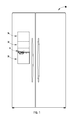
- FIG. 1 is a front elevational view of one embodiment of a refrigerator according to the present invention
- FIG. 2 is a top perspective view of one embodiment of an ice transfer device while receiving ice
- FIG. 3 is a top perspective view of the ice transfer device of FIG. 3 while dispensing ice;
- FIG. 4 is a top perspective view of an ice dispenser in an appliance door
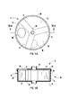
- FIG. 5A is a top plan view of the ice dispenser of FIG. 3 ;
- FIG. 5B is a side cross-sectional view of the ice dispenser of FIG. 5A taken at line VB-VB;
- FIG. 6A is a top plan view of the ice dispenser with the lid raised during rotation of the chamber walls;
- FIG. 6B is a side cross-sectional view of the ice dispenser of FIG. 6A taken at line VIB-VIB;
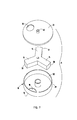
- FIG. 7 is a top perspective exploded view of the ice dispenser of FIG. 3 ;
- FIG. 8 is a top plan view of another embodiment of an ice dispenser
- FIG. 9 is a top plan view of another embodiment of an ice dispenser.
- FIG. 10 is a top plan view of another embodiment of an ice dispenser
- FIG. 11 is a top plan view of another embodiment of an ice dispenser
- FIG. 12 is a top plan view of another embodiment of an ice dispenser
- FIG. 13 is a top plan view of another embodiment of an ice dispenser
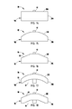
- FIG. 14 is a side elevational view of one embodiment of an ice dispenser side profile configuration
- FIG. 15 is a side elevational view of another embodiment of an ice dispenser side profile configuration
- FIG. 16 is a side elevational view of another embodiment of an ice dispenser side profile configuration
- FIG. 17 is a side elevational view of another embodiment of an ice dispenser side profile configuration.
- FIG. 18 is a side elevational view of another embodiment of an ice dispenser side profile configuration.
- the reference numeral 10 generally designates an appliance that includes an ice transfer device 9 having an ice-containing member 11 with a plurality of interior chambers 12 separated by substantially radially-extending chamber walls 14.
- a base 16 is disposed below the ice-containing member 11 and includes an ice-dispensing aperture 18.
- a lid 20 is adjacent to the ice-containing member 11 and operable between a first position 22 wherein the lid 20 is in abutting contact with the ice-containing member and a second position 24 wherein the lid 20 is spaced a predetermined distance from the chamber walls 14.
- the ice-containing member 11 is adapted for use over an ice dispenser 26 having a trap door 28.
- the ice-containing member 11 includes a sidewall 29 that rests on the base 16 to form a cylindrical configuration wherein the lid 20 is adapted for vertical translation relative to the chamber walls 14.
- the lid 20 includes an ice-receiving aperture 30 that is disposed generally substantially below an ice bin 32.
- the ice bin 32 receives and stores ice from an ice-maker 34 operably connected with the ice bin 32.
- the ice bin 32 When a user desires ice 36, and activates an actuator 38 in the appliance 10, the ice bin 32 deposits ice 36 that is generated in the ice-maker 34 through the ice-receiving aperture 30 into one of the plurality of interior chambers 12.
- the ice 36 cascades into the chamber 12 onto the base 16 until the amount of ice reaches a predetermined maximum volume.
- the maximum volume is determined based on data collected from a weight sensor, ice level sensor, etc.
- the chamber walls 14 rotate counterclockwise in the direction of arrow 40, which consequently rotates the ice 36 disposed in the ice-filled interior chamber 12.
- the ice 36 is moved over the base 16 and eventually slides over the ice-dispensing aperture 18 disposed above the trapdoor 28 of the ice dispenser 26.
- the ice 36 cascades downward through the ice-dispensing aperture 18, through the trapdoor 28 and out of the ice dispenser 26 into the waiting cup of a user. If more ice 36 is desired, then the process outlined above repeats until sufficient ice 36 has been dispensed to the user or until the ice bin 32 has been emptied.
- the ice-containing member 11 is rotatably connected with a vertically-extending pivot pin 40 that allows for rotational movement of the ice-containing member 11.
- the pivot pin 40 may extend upward from the lid 20, downward from the base 16 or both.
- the lid 20 is adapted to move vertically upward and downward relative to the chamber walls 14 and sidewall 29.
- the lid 20 elevates slightly ( FIG. 6B ) to minimize frictional resistance between the rotating chamber walls 14 and the lid 20.
- the lid 20 descends into abutting contact with the chamber walls 14.
- the combination of the lid 20, chamber walls 14 and the base 16, provide an efficient thermal barrier that minimizes the amount of cool air that leaves the appliance 10, while at the same time minimizing the amount of warm air that enters the appliance 10.
- the chamber walls 14 are arranged symmetrically inside the ice-containing member 11 and are specifically designed to direct ice from the chamber 14 out of and through the ice-dispensing aperture 18.
- Each chamber wall 14 includes an arcuate outer end 50 that complements the interior circumferential area 52 of the sidewall 29.
- the lid 20 is sealed against the sidewall 29 with the chamber walls 14 disposed between the lid 20 and the housing 29.
- FIG. 8 illustrates a linear chamber wall construction 60 wherein the chamber walls 14A effectively dispense ice using two chambers 12A.
- FIG. 9 illustrates a second linear chamber wall construction 62 with four chamber walls 14B that effectively dispense ice using four chambers 12B.
- FIG. 10 illustrates yet another linear chamber wall construction embodiment 64 that includes three chambers 12C with three linear chamber walls 14C.
- FIG. 11 illustrates an offset chamber wall construction 66 that is a variation of the embodiment of FIG. 10 with chamber walls 14D that include an offset portion that form offset chambers 12D.
- FIG. 12 illustrates a sweeper wall construction 68 that is another variation of the embodiment illustrated in Fig. 10 , with chambers 12E separated by thin chamber walls 14E that also include a thick flanged end 69.
- FIG. 13 3 illustrates an arcuate wall construction 70 having three chambers 12F, that are divided by arcuate chamber walls 14F that include an arcuate portion. It will be understood by a person having ordinary skill in the art that any number of possible configuration could be used and that the end use may define which embodiment is most beneficial to a user.
- the ice-containing member 11 may also have a variety of side profile configurations.
- the ice-containing member 11A may have a standard cylindrical configuration 80 with a planar circular lid 20A and a cylindrical sidewall 29A.
- the ice-containing member 11B has an arcuate top embodiment 82 includes a lid 20B that has an arcuate cross-section and which is disposed on a cylindrical sidewall 29B. This construction may accommodate a high ice volume.
- FIG. 16 includes ice-containing member 11C with a cylindrical sidewall 29C and a lid 20C with downwardly slanting walls 83 that also allow for increased capacity for storing ice 52.
- the arcuate construction 86 illustrated in FIG. 17 includes an ice-containing member I I D with a cylindrical sidewall 29D and a lid 20D with an arcuate cross section.
- An arcuate lower cavity area 87 is formed under the ice-containing member 11D which causes ice 52, under the force of gravity, to flow to the outside edges of the ice-containing member 11D. This functionality aids in directing ice 52 to the ice-dispensing aperture 18 during ice dispensing.
- FIG. 18 is similar to FIG. 17 , but the lid 20E includes downwardly slanting walls on a cylindrical sidewall 29E.
- a lower cavity 90 is formed below the ice-containing member 11E.
- the stops effectively locate the ice-receiving aperture in the lid 20 in position under an ice maker 32 and above a first chamber 12a while at the same time locating a second chamber 12b over the ice-dispensing aperture 18.
Landscapes
- Engineering & Computer Science (AREA)
- Physics & Mathematics (AREA)
- Mechanical Engineering (AREA)
- Thermal Sciences (AREA)
- General Engineering & Computer Science (AREA)
- Production, Working, Storing, Or Distribution Of Ice (AREA)
- Confectionery (AREA)
Abstract
Description
- The present invention generally relates to an ice transfer device, and more specifically, to an ice transfer device with a revolving chamber.
- In one aspect of the present invention, an ice transfer device includes an ice-containing member having a plurality of interior chambers separated by substantially radially-extending chamber walls. A base is disposed below the ice-containing member and includes an ice-dispensing aperture. A lid is adjacent to the ice-containing member and operable between a first position wherein the lid is in abutting contact with the ice-containing member and a second position wherein the lid is spaced a predetermined distance from the chamber walls.
- In another aspect of the present invention, an ice transfer device includes an ice-containing member having a cylindrical exterior shape and a plurality of interior chambers. A base is disposed below the ice-containing member and includes an ice-dispensing aperture. A housing extends over the ice-containing member. The housing generally conforms to the exterior shape of the ice-containing member. The housing includes an ice-receiving aperture vertically offset from the base aperture.
- In yet another aspect of the present invention, a method of making ice through an ice dispenser includes forming a horizontally-rotating ice-containing member. A plurality of chambers are formed inside the ice-containing member that are defined by substantially radially-extending chamber walls. The ice-containing member is covered with a translocatable lid. An ice-receiving aperture is provided in the lid vertically offset from the base aperture. A base is provided below the ice-containing member, the base including an ice-dispensing aperture.
- These and other features, advantages, and objects of the present invention will be further understood and appreciated by those skilled in the art upon studying the following specification, claims, and appended drawings.
-
FIG. 1 is a front elevational view of one embodiment of a refrigerator according to the present invention; -
FIG. 2 is a top perspective view of one embodiment of an ice transfer device while receiving ice; -
FIG. 3 is a top perspective view of the ice transfer device ofFIG. 3 while dispensing ice; -
FIG. 4 is a top perspective view of an ice dispenser in an appliance door; -
FIG. 5A is a top plan view of the ice dispenser ofFIG. 3 ; -
FIG. 5B is a side cross-sectional view of the ice dispenser ofFIG. 5A taken at line VB-VB; -
FIG. 6A is a top plan view of the ice dispenser with the lid raised during rotation of the chamber walls; -
FIG. 6B is a side cross-sectional view of the ice dispenser ofFIG. 6A taken at line VIB-VIB; -
FIG. 7 is a top perspective exploded view of the ice dispenser ofFIG. 3 ; -
FIG. 8 is a top plan view of another embodiment of an ice dispenser; -
FIG. 9 is a top plan view of another embodiment of an ice dispenser; -
FIG. 10 is a top plan view of another embodiment of an ice dispenser; -
FIG. 11 is a top plan view of another embodiment of an ice dispenser; -
FIG. 12 is a top plan view of another embodiment of an ice dispenser; -
FIG. 13 is a top plan view of another embodiment of an ice dispenser; -
FIG. 14 is a side elevational view of one embodiment of an ice dispenser side profile configuration; -
FIG. 15 is a side elevational view of another embodiment of an ice dispenser side profile configuration; -
FIG. 16 is a side elevational view of another embodiment of an ice dispenser side profile configuration; -
FIG. 17 is a side elevational view of another embodiment of an ice dispenser side profile configuration; and -
FIG. 18 is a side elevational view of another embodiment of an ice dispenser side profile configuration. - For purposes of description herein the terms "upper," "lower," "right," "left," "rear," "front," "vertical," "horizontal," and derivatives thereof shall relate to the invention as oriented in
FIGS. 1 and2 . However, it is to be understood that the invention may assume various alternative orientations and step sequences, except where expressly specified to the contrary. It is also to be understood that the specific devices and processes illustrated in the attached drawings, and described in the following specification are simply exemplary embodiments of the inventive concepts defined in the appended claims. Hence, specific dimensions and other physical characteristics relating to the embodiments disclosed herein are not to be considered as limiting, unless the claims expressly state otherwise. - Referring to the embodiment illustrated in
FIG. 1-3 , thereference numeral 10 generally designates an appliance that includes anice transfer device 9 having an ice-containingmember 11 with a plurality ofinterior chambers 12 separated by substantially radially-extendingchamber walls 14. Abase 16 is disposed below the ice-containingmember 11 and includes an ice-dispensingaperture 18. Alid 20 is adjacent to the ice-containingmember 11 and operable between afirst position 22 wherein thelid 20 is in abutting contact with the ice-containing member and asecond position 24 wherein thelid 20 is spaced a predetermined distance from thechamber walls 14. - Referring now to the embodiment illustrated in
FIGS. 2-4 , the ice-containingmember 11 is adapted for use over anice dispenser 26 having atrap door 28. The ice-containingmember 11 includes asidewall 29 that rests on thebase 16 to form a cylindrical configuration wherein thelid 20 is adapted for vertical translation relative to thechamber walls 14. Thelid 20 includes an ice-receivingaperture 30 that is disposed generally substantially below anice bin 32. Theice bin 32 receives and stores ice from an ice-maker 34 operably connected with theice bin 32. When a user desiresice 36, and activates anactuator 38 in theappliance 10, theice bin 32deposits ice 36 that is generated in the ice-maker 34 through the ice-receivingaperture 30 into one of the plurality ofinterior chambers 12. Theice 36 cascades into thechamber 12 onto thebase 16 until the amount of ice reaches a predetermined maximum volume. The maximum volume is determined based on data collected from a weight sensor, ice level sensor, etc. After the predetermined maximum volume has been reached, or if the user deactivates the actuator before the predetermined maximum level can be reached, thechamber walls 14 rotate counterclockwise in the direction ofarrow 40, which consequently rotates theice 36 disposed in the ice-filledinterior chamber 12. As thechamber walls 14 rotate, theice 36 is moved over thebase 16 and eventually slides over the ice-dispensingaperture 18 disposed above thetrapdoor 28 of theice dispenser 26. Theice 36 cascades downward through the ice-dispensingaperture 18, through thetrapdoor 28 and out of the ice dispenser 26 into the waiting cup of a user. Ifmore ice 36 is desired, then the process outlined above repeats untilsufficient ice 36 has been dispensed to the user or until theice bin 32 has been emptied. - Referring again to
FIGS. 5A, 5B ,6A, and 6B , the ice-containingmember 11 is rotatably connected with a vertically-extendingpivot pin 40 that allows for rotational movement of the ice-containingmember 11. Thepivot pin 40 may extend upward from thelid 20, downward from the base 16 or both. Thelid 20 is adapted to move vertically upward and downward relative to thechamber walls 14 andsidewall 29. During use, thelid 20 elevates slightly (FIG. 6B ) to minimize frictional resistance between therotating chamber walls 14 and thelid 20. After thechamber walls 14 have stopped rotating, thelid 20 descends into abutting contact with thechamber walls 14. The combination of thelid 20,chamber walls 14 and thebase 16, provide an efficient thermal barrier that minimizes the amount of cool air that leaves theappliance 10, while at the same time minimizing the amount of warm air that enters theappliance 10. - Referring to
FIG. 7 , thechamber walls 14 are arranged symmetrically inside the ice-containingmember 11 and are specifically designed to direct ice from thechamber 14 out of and through the ice-dispensingaperture 18. Eachchamber wall 14 includes an arcuateouter end 50 that complements the interiorcircumferential area 52 of thesidewall 29. In another embodiment, thelid 20 is sealed against thesidewall 29 with thechamber walls 14 disposed between thelid 20 and thehousing 29. - As shown in the illustrated embodiments of
FIGS. 8-13 , thechamber walls 14 of the ice-transfer device 9 may have various configurations.FIG. 8 illustrates a linearchamber wall construction 60 wherein thechamber walls 14A effectively dispense ice using twochambers 12A.FIG. 9 illustrates a second linearchamber wall construction 62 with fourchamber walls 14B that effectively dispense ice using fourchambers 12B.FIG. 10 illustrates yet another linear chamberwall construction embodiment 64 that includes threechambers 12C with threelinear chamber walls 14C.FIG. 11 illustrates an offsetchamber wall construction 66 that is a variation of the embodiment ofFIG. 10 withchamber walls 14D that include an offset portion that form offsetchambers 12D. Thechamber walls 14D ofFIG. 11 are designed to provide additional guidance ofice 36 to the ice-dispensingaperture 18.FIG. 12 illustrates asweeper wall construction 68 that is another variation of the embodiment illustrated inFig. 10 , withchambers 12E separated bythin chamber walls 14E that also include a thick flanged end 69.FIG. 13 3 illustrates anarcuate wall construction 70 having threechambers 12F, that are divided byarcuate chamber walls 14F that include an arcuate portion. It will be understood by a person having ordinary skill in the art that any number of possible configuration could be used and that the end use may define which embodiment is most beneficial to a user. - Referring now to
FIGS. 14-18 , the ice-containingmember 11 may also have a variety of side profile configurations. As shown inFIG. 14 , the ice-containingmember 11A may have a standardcylindrical configuration 80 with a planarcircular lid 20A and acylindrical sidewall 29A. Alternatively, as shown inFIG. 15 the ice-containingmember 11B has an arcuatetop embodiment 82 includes alid 20B that has an arcuate cross-section and which is disposed on acylindrical sidewall 29B. This construction may accommodate a high ice volume. The slanttop embodiment 84 shown inFIG. 16 includes ice-containingmember 11C with acylindrical sidewall 29C and a lid 20C with downwardly slantingwalls 83 that also allow for increased capacity for storingice 52. Thearcuate construction 86 illustrated inFIG. 17 includes an ice-containing member I I D with acylindrical sidewall 29D and alid 20D with an arcuate cross section. An arcuate lower cavity area 87 is formed under the ice-containingmember 11D which causesice 52, under the force of gravity, to flow to the outside edges of the ice-containingmember 11D. This functionality aids in directingice 52 to the ice-dispensingaperture 18 during ice dispensing.FIG. 18 is similar toFIG. 17 , but thelid 20E includes downwardly slanting walls on acylindrical sidewall 29E. Alower cavity 90 is formed below the ice-containingmember 11E. - It is contemplated that there may be stops disposed on the ice-containing
member 10 that hold the ice-containingmember 10 in position or a sensor that effectively locates the chambers in correct rotational alignment during an ice-dispensing event. The stops effectively locate the ice-receiving aperture in thelid 20 in position under anice maker 32 and above a first chamber 12a while at the same time locating a second chamber 12b over the ice-dispensingaperture 18.
Claims (14)
- An ice transfer device (9) comprising:an ice-containing member (11) including a plurality of interior chambers (12) separated by substantially radially-extending chamber walls (14);a base (16) disposed below the ice-containing member (11) and having an ice-dispensing aperture (18);a lid (20) adjacent to the ice-containing member and operable between a first position, wherein the lid is in abutting contact with the ice-containing member (11) and a second position, wherein the lid (20) is spaced a predetermined distance from the housing.
- The ice transfer device of claim 1, further comprising:an ice-receiving aperture (30) disposed in the lid (20).
- The ice transfer device of claim 2, wherein the ice-receiving aperture (30) is vertically offset from the ice dispensing aperture (18).
- The ice transfer device of claim 2, wherein a chamber wall is disposed horizontally between the ice-receiving aperture (30) and the ice-dispensing aperture (18).
- The ice transfer device of claim 1, further comprising:a lower cavity area disposed under the ice-containing member (11).
- The ice transfer device of any of the preceding claims, wherein the ice-containing member (11) has a cylindrical exterior shape with a central axis and includes a plurality of chamber walls (14) rotatable about the central axis, the lid being vertically adjustable relative to the ice-containing member.
- The ice transfer device of claim 6, further comprising:a pivot pin disposed proximate the central axis.
- The ice transfer device of claim 6, wherein the lid (20) has an arcuate cross-section.
- The ice transfer device of claim 6, wherein one of the plurality of chamber walls (14) is disposed horizontally between the ice-receiving aperture and the ice-dispensing aperture.
- The ice transfer device of claim 6, wherein the lid (20) includes downwardly slanting walls.
- The ice transfer device of claim 6, wherein the chamber walls (14) have an arcuate shape.
- The ice transfer device of claim 6, wherein the chamber walls (14) have an offset portion.
- The ice transfer device of claim 6, wherein the chamber walls (14) include a flanged end.
- The ice transfer device of claim 6, wherein each chamber wall (14) includes an arcuate outer end that complements an interior circumferential area of the ice-containing member.
Applications Claiming Priority (1)
| Application Number | Priority Date | Filing Date | Title |
|---|---|---|---|
| US12/612,147 US8714414B2 (en) | 2009-11-04 | 2009-11-04 | Ice transfer device |
Publications (2)
| Publication Number | Publication Date |
|---|---|
| EP2320172A2 true EP2320172A2 (en) | 2011-05-11 |
| EP2320172A3 EP2320172A3 (en) | 2017-12-13 |
Family
ID=43530259
Family Applications (1)
| Application Number | Title | Priority Date | Filing Date |
|---|---|---|---|
| EP10188803.0A Withdrawn EP2320172A3 (en) | 2009-11-04 | 2010-10-26 | Ice transfer device |
Country Status (2)
| Country | Link |
|---|---|
| US (1) | US8714414B2 (en) |
| EP (1) | EP2320172A3 (en) |
Cited By (1)
| Publication number | Priority date | Publication date | Assignee | Title |
|---|---|---|---|---|
| CN105546899A (en) * | 2016-01-29 | 2016-05-04 | 合肥华凌股份有限公司 | Ice selection bucket for automatic ice making machine of refrigerator and ice making machine |
Families Citing this family (8)
| Publication number | Priority date | Publication date | Assignee | Title |
|---|---|---|---|---|
| US20130042644A1 (en) * | 2011-08-17 | 2013-02-21 | Alan Joseph Mitchell | Fluidizer for an ice dispensing assembly of a cooling compartment |
| US20160207692A1 (en) * | 2012-11-12 | 2016-07-21 | Jose L. Martinez | Dry food dispenser |
| US20140131384A1 (en) * | 2012-11-12 | 2014-05-15 | Jose L MARTINEZ | Personal Cereal Dispenser |
| JP6442842B2 (en) | 2014-03-14 | 2019-01-09 | 富士電機株式会社 | Ice feeder |
| KR102421480B1 (en) * | 2014-10-06 | 2022-07-15 | 아이스브레이커 노르딕 에이피에스 | Ice cube producing unit |
| US10753666B2 (en) * | 2014-10-06 | 2020-08-25 | Icebreaker Nordic Aps | Ice cube producing unit |
| CN108759216B (en) * | 2018-05-21 | 2020-11-20 | 海尔智家股份有限公司 | Ice crusher and refrigerator |
| CN108759218B (en) * | 2018-05-21 | 2020-11-20 | 海尔智家股份有限公司 | Ice crusher and refrigerator |
Family Cites Families (20)
| Publication number | Priority date | Publication date | Assignee | Title |
|---|---|---|---|---|
| US3101872A (en) * | 1960-06-24 | 1963-08-27 | Continental Vending Machine Co | Ice storing and dispensing mechanism for beverage dispensing machines and the like |
| US3075363A (en) * | 1960-12-16 | 1963-01-29 | Freez King Corp | Ice dispensing attachment for beverage dispensing machine |
| US3207366A (en) * | 1962-12-03 | 1965-09-21 | Jr Robert B Feistel | Ice cube making and vending machine |
| US3747363A (en) * | 1972-05-30 | 1973-07-24 | Gen Electric | Refrigerator including through-the-door ice service |
| US3798923A (en) * | 1972-07-14 | 1974-03-26 | Amana Refrigeration Inc | Refrigerator with ice dispensing means |
| US3881642A (en) * | 1973-09-10 | 1975-05-06 | King Seeley Thermos Co | Ice dispensing apparatus |
| US3874559A (en) * | 1974-01-16 | 1975-04-01 | John J Pink | Ice dispenser for freezer-refrigerators and the like |
| US4049161A (en) * | 1974-01-28 | 1977-09-20 | King-Seeley Thermos Co. | Ice making and vending machine |
| US4123918A (en) * | 1976-12-09 | 1978-11-07 | King-Seeley Thermos Co. | Ice dispensing machine |
| US4158426A (en) * | 1977-04-21 | 1979-06-19 | Whirlpool Corporation | Dispensing system and method for dispensing discrete elements |
| US4227383A (en) * | 1979-05-04 | 1980-10-14 | General Electric Company | Refrigerator including through-the-door ice service |
| US4930685A (en) * | 1988-02-26 | 1990-06-05 | Servend International, Inc. | Ice dispensing apparatus and method |
| JPH02194324A (en) | 1989-01-24 | 1990-07-31 | K L J Kk | Ground ice metering machine |
| NL1000603C2 (en) * | 1995-06-20 | 1996-12-23 | Rachid Miliani | Device for dosing and delivering solids. |
| US6062426A (en) * | 1998-05-01 | 2000-05-16 | North Star Ice Equipment Corporation | Ice storage/dispensing apparatus |
| KR100510698B1 (en) * | 2003-09-17 | 2005-08-31 | 엘지전자 주식회사 | Dispenser for ice-making apparatus in the refrigerator |
| US7175046B2 (en) * | 2004-06-21 | 2007-02-13 | Shen-Hao Yao | Merchandise output device of a vending machine |
| WO2006036835A2 (en) * | 2004-09-24 | 2006-04-06 | Robert Kinzie | Programmable dispensing apparatus |
| US7743622B2 (en) * | 2006-12-08 | 2010-06-29 | Whirlpool Corporation | Ice dispensing and detecting apparatus |
| US8220283B2 (en) * | 2006-12-21 | 2012-07-17 | Whirlpool Corporation | Ice crushing mechanism |
-
2009
- 2009-11-04 US US12/612,147 patent/US8714414B2/en not_active Expired - Fee Related
-
2010
- 2010-10-26 EP EP10188803.0A patent/EP2320172A3/en not_active Withdrawn
Non-Patent Citations (1)
| Title |
|---|
| None |
Cited By (1)
| Publication number | Priority date | Publication date | Assignee | Title |
|---|---|---|---|---|
| CN105546899A (en) * | 2016-01-29 | 2016-05-04 | 合肥华凌股份有限公司 | Ice selection bucket for automatic ice making machine of refrigerator and ice making machine |
Also Published As
| Publication number | Publication date |
|---|---|
| US20110101033A1 (en) | 2011-05-05 |
| EP2320172A3 (en) | 2017-12-13 |
| US8714414B2 (en) | 2014-05-06 |
Similar Documents
| Publication | Publication Date | Title |
|---|---|---|
| US8714414B2 (en) | Ice transfer device | |
| EP2674702B1 (en) | Refrigerator | |
| US9239181B2 (en) | Refrigerator with ice maker in freezing compartment and transfer device to ice bank in refrigerating compartment | |
| EP1930673B1 (en) | Ice dispensing and detecting apparatus | |
| US9841217B2 (en) | Ice making device, refrigerator including ice making device, and method of controlling refrigerator | |
| MXPA04003411A (en) | Device for making ice in refrigerated cabinets. | |
| EP2679939B1 (en) | Refrigerator | |
| CA2793581C (en) | Ice dispenser with crusher for a refrigerator appliance | |
| US6321802B1 (en) | Ice and beverage dispensing apparatus | |
| US8522571B2 (en) | Variable capacity ice storage assembly | |
| US20190145686A1 (en) | Refrigerator | |
| US10006689B2 (en) | Modular bucket and door architecture to deliver three ice functions | |
| EP3299749B1 (en) | Refrigerator | |
| EP2333462B1 (en) | Three forms of ice from a single well | |
| US12546525B2 (en) | Dispenser assembly for stand-alone ice making appliance | |
| US12429270B2 (en) | Refrigerator appliances and removable ice making assemblies | |
| US8220283B2 (en) | Ice crushing mechanism | |
| WO2023131079A1 (en) | Ice-making assembly for refrigeration appliance and refrigeration appliance | |
| US11262116B2 (en) | Refrigerator appliance having a removable ice storage bin | |
| KR20060133729A (en) | Refrigerator ice maker | |
| US8984899B2 (en) | Refrigerator appliance with ice dispenser | |
| US12222149B2 (en) | Refrigerator appliances and ice making assemblies having one or more ice ejection cams | |
| US20250237423A1 (en) | Dispenser assembly for stand-alone ice making appliance | |
| CN120232211A (en) | An ice making machine | |
| US20180299177A1 (en) | Ice maker assembly and refrigerator appliance |
Legal Events
| Date | Code | Title | Description |
|---|---|---|---|
| PUAI | Public reference made under article 153(3) epc to a published international application that has entered the european phase |
Free format text: ORIGINAL CODE: 0009012 |
|
| AK | Designated contracting states |
Kind code of ref document: A2 Designated state(s): AL AT BE BG CH CY CZ DE DK EE ES FI FR GB GR HR HU IE IS IT LI LT LU LV MC MK MT NL NO PL PT RO RS SE SI SK SM TR |
|
| AX | Request for extension of the european patent |
Extension state: BA ME |
|
| PUAL | Search report despatched |
Free format text: ORIGINAL CODE: 0009013 |
|
| AK | Designated contracting states |
Kind code of ref document: A3 Designated state(s): AL AT BE BG CH CY CZ DE DK EE ES FI FR GB GR HR HU IE IS IT LI LT LU LV MC MK MT NL NO PL PT RO RS SE SI SK SM TR |
|
| AX | Request for extension of the european patent |
Extension state: BA ME |
|
| RIC1 | Information provided on ipc code assigned before grant |
Ipc: F25C 5/00 20060101AFI20171107BHEP |
|
| STAA | Information on the status of an ep patent application or granted ep patent |
Free format text: STATUS: THE APPLICATION HAS BEEN PUBLISHED |
|
| STAA | Information on the status of an ep patent application or granted ep patent |
Free format text: STATUS: THE APPLICATION IS DEEMED TO BE WITHDRAWN |
|
| 18D | Application deemed to be withdrawn |
Effective date: 20180614 |