EP2320078A2 - Method for operating a wind turbine with reduced blade fouling - Google Patents
Method for operating a wind turbine with reduced blade fouling Download PDFInfo
- Publication number
- EP2320078A2 EP2320078A2 EP20100189248 EP10189248A EP2320078A2 EP 2320078 A2 EP2320078 A2 EP 2320078A2 EP 20100189248 EP20100189248 EP 20100189248 EP 10189248 A EP10189248 A EP 10189248A EP 2320078 A2 EP2320078 A2 EP 2320078A2
- Authority
- EP
- European Patent Office
- Prior art keywords
- wind turbine
- mode
- rotor blade
- afc
- environmental condition
- Prior art date
- Legal status (The legal status is an assumption and is not a legal conclusion. Google has not performed a legal analysis and makes no representation as to the accuracy of the status listed.)
- Granted
Links
- 230000002829 reductive effect Effects 0.000 title claims abstract description 15
- 238000000034 method Methods 0.000 title claims description 97
- 230000007613 environmental effect Effects 0.000 claims abstract description 66
- 241000238631 Hexapoda Species 0.000 claims description 44
- 239000000443 aerosol Substances 0.000 claims description 30
- 238000001556 precipitation Methods 0.000 claims description 15
- 239000000356 contaminant Substances 0.000 claims description 6
- 239000002245 particle Substances 0.000 claims description 5
- 230000001376 precipitating effect Effects 0.000 claims description 5
- 230000002441 reversible effect Effects 0.000 claims description 4
- 239000007789 gas Substances 0.000 description 93
- 239000003570 air Substances 0.000 description 21
- XLYOFNOQVPJJNP-UHFFFAOYSA-N water Substances O XLYOFNOQVPJJNP-UHFFFAOYSA-N 0.000 description 20
- 239000012535 impurity Substances 0.000 description 14
- 238000000926 separation method Methods 0.000 description 8
- 238000007664 blowing Methods 0.000 description 7
- 238000004140 cleaning Methods 0.000 description 7
- 238000011144 upstream manufacturing Methods 0.000 description 7
- 230000000903 blocking effect Effects 0.000 description 6
- 230000006870 function Effects 0.000 description 5
- 238000004519 manufacturing process Methods 0.000 description 5
- 230000008569 process Effects 0.000 description 5
- 239000000428 dust Substances 0.000 description 4
- 230000000694 effects Effects 0.000 description 4
- 239000012530 fluid Substances 0.000 description 4
- 230000003068 static effect Effects 0.000 description 4
- 230000003111 delayed effect Effects 0.000 description 3
- 238000012986 modification Methods 0.000 description 3
- 230000004048 modification Effects 0.000 description 3
- CURLTUGMZLYLDI-UHFFFAOYSA-N Carbon dioxide Chemical compound O=C=O CURLTUGMZLYLDI-UHFFFAOYSA-N 0.000 description 2
- 241001465754 Metazoa Species 0.000 description 2
- 238000013461 design Methods 0.000 description 2
- 238000005516 engineering process Methods 0.000 description 2
- 230000000977 initiatory effect Effects 0.000 description 2
- 230000000670 limiting effect Effects 0.000 description 2
- 238000012544 monitoring process Methods 0.000 description 2
- 230000002265 prevention Effects 0.000 description 2
- 238000005086 pumping Methods 0.000 description 2
- 238000009987 spinning Methods 0.000 description 2
- IJGRMHOSHXDMSA-UHFFFAOYSA-N Atomic nitrogen Chemical compound N#N IJGRMHOSHXDMSA-UHFFFAOYSA-N 0.000 description 1
- 239000012080 ambient air Substances 0.000 description 1
- 230000009286 beneficial effect Effects 0.000 description 1
- 239000006227 byproduct Substances 0.000 description 1
- 239000001569 carbon dioxide Substances 0.000 description 1
- 229910002092 carbon dioxide Inorganic materials 0.000 description 1
- 230000008859 change Effects 0.000 description 1
- 238000011109 contamination Methods 0.000 description 1
- 230000001419 dependent effect Effects 0.000 description 1
- 238000001514 detection method Methods 0.000 description 1
- 210000003608 fece Anatomy 0.000 description 1
- 230000005484 gravity Effects 0.000 description 1
- 230000005012 migration Effects 0.000 description 1
- 238000013508 migration Methods 0.000 description 1
- JCXJVPUVTGWSNB-UHFFFAOYSA-N nitrogen dioxide Inorganic materials O=[N]=O JCXJVPUVTGWSNB-UHFFFAOYSA-N 0.000 description 1
- 238000005457 optimization Methods 0.000 description 1
- 230000036961 partial effect Effects 0.000 description 1
- 230000003449 preventive effect Effects 0.000 description 1
- 238000011160 research Methods 0.000 description 1
- 230000004044 response Effects 0.000 description 1
- 241000894007 species Species 0.000 description 1
- 238000009736 wetting Methods 0.000 description 1
Images



Classifications
-
- F—MECHANICAL ENGINEERING; LIGHTING; HEATING; WEAPONS; BLASTING
- F03—MACHINES OR ENGINES FOR LIQUIDS; WIND, SPRING, OR WEIGHT MOTORS; PRODUCING MECHANICAL POWER OR A REACTIVE PROPULSIVE THRUST, NOT OTHERWISE PROVIDED FOR
- F03D—WIND MOTORS
- F03D7/00—Controlling wind motors
- F03D7/02—Controlling wind motors the wind motors having rotation axis substantially parallel to the air flow entering the rotor
- F03D7/04—Automatic control; Regulation
- F03D7/042—Automatic control; Regulation by means of an electrical or electronic controller
-
- F—MECHANICAL ENGINEERING; LIGHTING; HEATING; WEAPONS; BLASTING
- F03—MACHINES OR ENGINES FOR LIQUIDS; WIND, SPRING, OR WEIGHT MOTORS; PRODUCING MECHANICAL POWER OR A REACTIVE PROPULSIVE THRUST, NOT OTHERWISE PROVIDED FOR
- F03D—WIND MOTORS
- F03D7/00—Controlling wind motors
- F03D7/02—Controlling wind motors the wind motors having rotation axis substantially parallel to the air flow entering the rotor
- F03D7/022—Adjusting aerodynamic properties of the blades
-
- F—MECHANICAL ENGINEERING; LIGHTING; HEATING; WEAPONS; BLASTING
- F03—MACHINES OR ENGINES FOR LIQUIDS; WIND, SPRING, OR WEIGHT MOTORS; PRODUCING MECHANICAL POWER OR A REACTIVE PROPULSIVE THRUST, NOT OTHERWISE PROVIDED FOR
- F03D—WIND MOTORS
- F03D80/00—Details, components or accessories not provided for in groups F03D1/00 - F03D17/00
- F03D80/50—Maintenance or repair
- F03D80/55—Cleaning
-
- F—MECHANICAL ENGINEERING; LIGHTING; HEATING; WEAPONS; BLASTING
- F05—INDEXING SCHEMES RELATING TO ENGINES OR PUMPS IN VARIOUS SUBCLASSES OF CLASSES F01-F04
- F05B—INDEXING SCHEME RELATING TO WIND, SPRING, WEIGHT, INERTIA OR LIKE MOTORS, TO MACHINES OR ENGINES FOR LIQUIDS COVERED BY SUBCLASSES F03B, F03D AND F03G
- F05B2240/00—Components
- F05B2240/20—Rotors
- F05B2240/30—Characteristics of rotor blades, i.e. of any element transforming dynamic fluid energy to or from rotational energy and being attached to a rotor
-
- F—MECHANICAL ENGINEERING; LIGHTING; HEATING; WEAPONS; BLASTING
- F05—INDEXING SCHEMES RELATING TO ENGINES OR PUMPS IN VARIOUS SUBCLASSES OF CLASSES F01-F04
- F05B—INDEXING SCHEME RELATING TO WIND, SPRING, WEIGHT, INERTIA OR LIKE MOTORS, TO MACHINES OR ENGINES FOR LIQUIDS COVERED BY SUBCLASSES F03B, F03D AND F03G
- F05B2260/00—Function
- F05B2260/60—Fluid transfer
- F05B2260/63—Preventing clogging or obstruction of flow paths by dirt, dust, or foreign particles
-
- F—MECHANICAL ENGINEERING; LIGHTING; HEATING; WEAPONS; BLASTING
- F05—INDEXING SCHEMES RELATING TO ENGINES OR PUMPS IN VARIOUS SUBCLASSES OF CLASSES F01-F04
- F05B—INDEXING SCHEME RELATING TO WIND, SPRING, WEIGHT, INERTIA OR LIKE MOTORS, TO MACHINES OR ENGINES FOR LIQUIDS COVERED BY SUBCLASSES F03B, F03D AND F03G
- F05B2260/00—Function
- F05B2260/80—Diagnostics
-
- F—MECHANICAL ENGINEERING; LIGHTING; HEATING; WEAPONS; BLASTING
- F05—INDEXING SCHEMES RELATING TO ENGINES OR PUMPS IN VARIOUS SUBCLASSES OF CLASSES F01-F04
- F05B—INDEXING SCHEME RELATING TO WIND, SPRING, WEIGHT, INERTIA OR LIKE MOTORS, TO MACHINES OR ENGINES FOR LIQUIDS COVERED BY SUBCLASSES F03B, F03D AND F03G
- F05B2270/00—Control
- F05B2270/80—Devices generating input signals, e.g. transducers, sensors, cameras or strain gauges
-
- Y—GENERAL TAGGING OF NEW TECHNOLOGICAL DEVELOPMENTS; GENERAL TAGGING OF CROSS-SECTIONAL TECHNOLOGIES SPANNING OVER SEVERAL SECTIONS OF THE IPC; TECHNICAL SUBJECTS COVERED BY FORMER USPC CROSS-REFERENCE ART COLLECTIONS [XRACs] AND DIGESTS
- Y02—TECHNOLOGIES OR APPLICATIONS FOR MITIGATION OR ADAPTATION AGAINST CLIMATE CHANGE
- Y02E—REDUCTION OF GREENHOUSE GAS [GHG] EMISSIONS, RELATED TO ENERGY GENERATION, TRANSMISSION OR DISTRIBUTION
- Y02E10/00—Energy generation through renewable energy sources
- Y02E10/70—Wind energy
- Y02E10/72—Wind turbines with rotation axis in wind direction
Definitions
- the present disclosure relates generally to methods of operating a wind turbine with reduced fouling, particularly to wind turbines having an active flow control (AFC) system, and a wind turbine including such AFC system.
- AFC active flow control
- AFC technologies try to avoid flow separation over rotor blades by actively modifying the wind flow proximate to the rotor blade. This can be achieved by ejecting gas through apertures formed in the surface of the rotor blade.
- Blade fouling can substantially lower the performance, in particular the extracted power of wind turbines.
- a method of operating a wind turbine has at least one rotor blade and an active flow control (AFC) system.
- the at least one rotor blade has at least one aperture defined through a surface thereof, and the AFC system is configured to modify aerodynamic properties of the at least one rotor blade by ejecting gas through the at least one aperture.
- the method includes operating the wind turbine in a first mode, determining an environmental condition surrounding the wind turbine indicative of fouling of the AFC system, and operating the wind turbine in a second mode different than the first mode based on the environmental condition. The second mode facilitates reducing fouling of the AFC system.
- a method of operating a wind turbine has at least one rotor blade and an active flow control (AFC) system.
- the at least one rotor blade includes at least one aperture defined through a surface of the at least one rotor blade, and the AFC system is configured to modify aerodynamic properties of the at least one rotor blade.
- the method includes determining an environmental condition surrounding the wind turbine indicative of precipitation, and adjusting at least one of a pitch angle and an azimuth angle of the at least one rotor blade such that the at least one aperture is wetted.
- a wind turbine in yet another aspect, includes at least one rotor blade and an active flow control (AFC) system at least partially defined in the at least one rotor blade.
- the AFC system is configured to modify aerodynamic properties of the at least one rotor blade.
- the wind turbine further includes a sensor configured to measure an environmental condition surrounding the wind turbine, and a wind turbine controller.
- the wind turbine controller is configured to operate the wind turbine in a first mode, and operate the wind turbine in a second mode different than the first mode depending on the environmental condition.
- the second mode includes adjusting at least one operation parameter of the wind turbine such that fouling of the AFC system is reduced.
- Modem wind turbines are designed to produce a maximum amount of energy. However, if the wind speed becomes too large and therefore changes an angle of attack above a certain value, flow separation over wind turbine blades occurs and results in stall. In such a situation, energy production by the turbine is reduced. If he flow separation over wind turbine blades can be delayed, the design of the wind turbine can be favorably changed, e.g. to increase the production of energy across the wind speed range and/or to change design parameters such as chord. This will eventually result in a considerable increase of wind turbine energy production.
- Flow separation over wind turbine blades can be delayed by blowing gas out of small apertures arranged at the surface of the rotor blade.
- the gas may be fed to the apertures through manifolds within the rotor blade by a gas supply.
- gases may be used, such as, but not limited to air, nitrogen, or carbon dioxide.
- air will be exemplarily used without any intention to limit the scope of the appended claims.
- the gas flow rate through the manifolds and out of the apertures is controlled by the gas supply. Controlling the gas flow rate results in delayed flow separation, which changes the aerodynamic properties of the rotor blade.
- the system including a gas supply, manifolds, and apertures, actively controls a gas flow out of the apertures of the rotor blade. This system is referred to as an active flow control (AFC) system.
- AFC active flow control
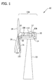
- Fig. 1 shows an exemplary wind turbine 10 having an AFC system 100, a sensor 12, and a wind turbine controller 14.
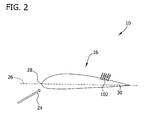
- Fig. 2 shows a chord-wise cross-sectional view of a rotor blade 16 being equipped with AFC system 100.
- wind turbine 10 includes three rotor blades 16, however, wind turbine 10 may include more or less than three rotor blades 16.
- Rotor blades 16 are mounted on a rotor hub 18 that is connected to a nacelle 20 fixed on top of a tower 22.
- Fig. 2 shows a position of AFC apertures 102 of rotor blade 16.
- rotor blade 16 is seen along a span-wise axis of rotor blade 16.
- a wind direction 24 impinges rotor blade 16 at an area slightly above where a chord line 26 intersects rotor blade 16 at a leading edge 28 of rotor blade 16.
- Aerodynamic properties of rotor blade 16 are changed by gas being ejected through apertures 102 defined through a surface 30 of rotor blade 16 on its suction side.
- Apertures 102 are typically positioned on the suction side of rotor blade 16 downwind of the airfoil maximum thickness. In Fig. 2 the suction side is an upper side of rotor blade 16. According to other embodiments, apertures 102 are positioned on a rotor blade section where flow separation mainly occurs.
- blade fouling of wind turbine 10, and especially fouling of apertures 102 and manifolds 104 included inside rotor blade 16, is avoided, or at least reduced, by operating wind turbine in a preventive manner such that AFC system 100, and especially manifolds 104 and apertures 102 of AFC system 100 collect less contamination or are not subject to contaminants in the first place.
- each rotor blade 16 includes at least one manifold 104. At a downstream end, manifold 104 is connected to at least one aperture 102 at surface 30 of rotor blade 16. For reasons of simplicity, only one rotor blade 16 with only one manifold 104 and one aperture 102 is depicted. However, a plurality of manifolds 104, typically of different lengths, can be provided within rotor blade 16. Furthermore, each manifold 104 is connected to a plurality of apertures 102. Although depicted only for one rotor blade 16, the other rotor blades 16 include manifolds 104 and apertures 102.
- manifold 104 is connected to a gas supply 106 from which gas is supplied to manifold 104.
- the terms "upstream” and "downstream” refer to gas flow directions within AFC system 100.
- the downstream direction is defined to be from gas supply 106 to aperture 102.
- the downstream direction is a direction of gas flow during an AFC mode in which gas is ejected through apertures 102 of rotor blades 16 in order to improve the aerodynamic properties of rotor blade 16.
- the upstream direction is defined as a direction from apertures 102 towards gas supply 106.
- gas supply 106 is located inside nacelle 20.
- gas supply 106 may also be located inside tower 22, inside rotor hub 18, and/or inside rotor blade 16. According to alternative embodiments, there is provided one gas supply 106 for each rotor blade 16. According to some of these embodiments, in each rotor blade 16 there is provided one gas supply 106.
- each manifold 104 is configured to channel gas and is connected to a valve 108.
- Each valve 108 is configured to block a gas flow to a respective manifold 104 and is positioned within nacelle 20 of wind turbine 10.
- Each valve 108 may be continuously adjusted from completely open to completely closed. It is to be understood that the term "blocking" does not necessarily mean complete blocking, I but may also imply partial blocking of manifolds 104. Valves 108 may thus have a flow control function. If valve 108 is not closed completely, the gas flow through the remaining valves 108 is not increased to the same extent as compared to the case when valve 108 closes completely.
- valves 108 may be replaced by other flow control devices which are configured to control gas flows of manifolds 104.
- valves 108 may also be positioned inside rotor hub 18, inside a rotor blade 16, or inside tower 22. The latter arrangement may be used when gas supply 106 is located inside tower 22.
- Manifolds 104 of rotor blades 16 are typically connected in parallel to gas supply 106 and may be blocked by their respective valves 108.
- An AFC controller 110 which may be included in or separate from wind turbine controller 14, controls valves 108 and gas supply 106. This control is indicated by arrows in Fig. 1 .
- the foregoing is merely exemplary and should not be construed as limiting because the present application also encompasses embodiments without valves 108.
- a gas flow rate through manifolds 104 is controlled by AFC controller 110.
- AFC controller 110 controls the gas flow rate through manifolds 104 by changing the gas flow rate of gas supply 106.
- AFC controller 110 controls the gas flow rate through manifolds 104 by blocking, e.g. manifold 104, thereby increasing the gas flow rate through the unblocked manifolds 104.
- AFC controller 110 may use valves 108. Each valve 108 may be continuously adjusted from completely open to completely closed, blocking the gas flow in the latter case.
- AFC controller 110 is part of AFC system 100, which includes manifolds 104, apertures 102, air supply 106, and valves 108. According to the embodiments described above, AFC system 100, particularly AFC controller 110, are configured to modify the aerodynamic properties of rotor blades 16 which typically results in delaying a flow separation over rotor blades 16.
- wind turbine controller 14 controls AFC controller 110, gas supply 106, and a pitch controller 32. According to further embodiments, wind turbine controller 14 further controls a yaw angle and/or a generator speed. Generally, wind turbine controller 14 is configured to adjust at least one operation parameter of wind turbine 10 based on an environmental condition measured by sensor 12 such that fouling of AFC system 100 is reduced. According to the embodiment shown in Fig. 1 , AFC controller 110 controls gas supply 106, while wind turbine controller 14 controls AFC controller 110. According to other embodiments, wind turbine controller 14 controls gas supply 106. Generally, wind turbine controller 14 may control any operation parameter of wind turbine 10. Operation parameters includes, but are not limited to including, a rotational speed, a pitch angle of rotor blades 16, a yaw angle, and/or a gas flow rate through AFC system 100, in particular through gas supply 106.
- Sensor 12 is configured to measure an environmental condition surrounding wind turbine 10.
- the environmental condition is indicative of fouling of AFC system 100.
- the environmental condition is processed by wind turbine controller 14 to determine how to operate wind turbine 10.
- sensor 12 may also be located in or at tower 22, inside rotor hub 18, inside rotor blade 16, and/or away from wind turbine 10.
- sensor 12 may be a weather station installed near wind turbine 10 or at least near a wind farm in which wind turbine 10 is located.
- the environmental condition includes, without limitation, an air humidity, a wind speed, an air temperature, an aerosol concentration, an airborne particle concentration, an airborne contaminants concentration, a concentration of any sort of flora, fauna, and/or any by-products thereof (e.g. fluff), a wind direction, a rain direction, a frequency of wind gusts, an atmospheric pressure, a wind chill factor, a cloud height, a cloud cover, a visibility, a dew point, a migration of birds and/or other animals, and/or a frequency and/or an amount of animal excrement, in particular bird droppings.
- any combination of two or more of the foregoing environmental conditions may be used to determine whether an increased risk for AFC fouling exists.
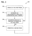
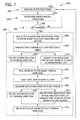
- Fig. 3 illustrates an exemplary method 200 of operating wind turbine 10 (shown in Fig. 1 ).
- Method 200 By performing method 200, fouling of rotor blade 16 (shown in Figs. 1 and 2 ) and/or AFC system 100 (shown in Fig. 1 ) is facilitated to be corrected and/or prevented.
- Method 200 is performed by wind turbine controller 14 (shown in Fig. 1 ) and/or AFC controller 110 (shown in Fig. 1 ) sending commands and/or instructions to components of wind turbine 10, such as AFC system 100 and/or any suitable component.
- Wind turbine controller 14 and/or AFC controller 110 is programmed with code segments configured to perform method 200.
- method 200 is encoded on a computer-readable medium that is readable by wind turbine controller 14 and/or AFC controller 110.
- wind turbine controller 14 and/or AFC controller 110 is configured to read computer-readable medium for performing method 200.
- method 200 includes operating 202 wind turbine 10 in a first mode, such as a normal mode.
- a normal mode refers to a mode of operating wind turbine 10 and/or AFC system 100 such that AFC system 100 a drives a flow of fluid to increase lift on at least one rotor blade 16.
- the normal mode includes normal operation over a substantially entire power curve; operating when a wind speed is too low to generate power but wind turbine 10 is prepared to generate power; using constant and variable speed-ranges; operating within a peak shaver range; operating in an above rated condition; and/or performing a storm cut out.
- Flow characteristics of the fluid flow during the normal mode are determined empirically and/or are predetermined to achieve optimal lift on rotor blade 16 depending on ambient conditions, such as a wind speed and/or a wind direction, precipitation, and/or other atmospheric and/or environmental conditions. At least one flow characteristic of the fluid flow may be adjusted and/or varied during the normal mode, based on changing ambient conditions and/or operating characteristics of wind turbine 10, to facilitate achieving optimal blade lift.
- Wind turbine 10 and/or AFC system 100 is operated 202 in the normal mode according to a predetermined schedule and/or based on wind conditions. For example, when wind speeds are high, operation 202 of AFC system 100 is substantially terminated because increased lift on rotor blade 16 is not desired in such wind conditions. However, even when active flow control is terminated, enough fluid is discharged from apertures 102 to facilitate preventing insects and/or other debris from flying into manifolds 104. Such termination of active flow control is considered to be part of the normal operating mode.
- wind turbine 10 determines 204 at least one environmental condition surrounding wind turbine 10. More specifically, wind turbine 10 collects data using sensor 12 and processes the data to determine 204 the environmental condition. Based on the environmental condition, it is determined 206 whether to operate wind turbine 10 in the normal mode or in a second mode, such as a cleaning mode.
- a second mode refers to a mode of operating wind turbine 10 and/or AFC system 100 to achieve an outcome in addition to or different than optimal lift on rotor blade 16.
- the term "optimal lift” refers to lift that maximizes power production and reduces the cost of power production, such as a lift that is optimized to account for initial costs of wind turbine 10 and/or a lift that produces a maximized ratio of annual energy capture over initial cost; however, any suitable optimization scheme can be used to achieve optimal lift.
- wind turbine 10 can be operated in more than two modes.
- the second mode is a mode that is intentionally beneficial for performing a cleaning operation rather than performing an operation target, such as capturing energy.
- AFC system 100 is controlled to facilitate removing debris from AFC system 100.
- the second mode includes at least one cleaning mode to facilitate removing debris from AFC system 100.
- wind turbine 10 By comparing the environmental condition with certain criteria, it is determined 206 whether to operate wind turbine 10 in the normal mode or in the second mode. If it is determined 206 to operate in the first mode, wind turbine 10 continues performing steps 202 and 204. If it is determined 206 to operate in the second mode, wind turbine 10 switches from the first mode to operate 208 in the second mode. Based on a time period, an operator's command, sensed environmental conditions, and/or any other suitable criteria, wind turbine 10 operates 208 in the second mode then returns to operating 202 in the first mode.
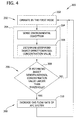
- Fig. 4 is a flowchart of a first example method 300 for operating wind turbine 10 (shown in Fig. 1 ).
- Method 300 includes at least some of the steps of method 200 (shown in Fig. 3 ) and, as such, similar steps are indicated with similar reference numbers.
- method 300 starts by determining 204 an environmental condition of wind turbine 10 indicative of fouling of AFC system 100 by sensing 304 an environmental condition using sensor 12. At least one sensed environmental condition is used to determine 306 specific values that indicate a higher risk of fouling of AFC system 100 of wind turbine 10. More specifically, estimated insect density and/or aerosol concentration are determined 306 from the sensed environmental condition.
- insect density, concentration of dust, impurities, or aerosols or the like are typical indicators that an elevated risk of AFC fouling exists.
- flying insects are likely to fly in the air next to wind turbine 10. Such flying insects may enter manifolds 104 of AFC system 100 via apertures 102, thus clogging manifolds 104 and apertures 102.
- fouling of AFC system 100 is more likely when there is a high concentration of dust particles or aerosols in the ambient air.
- Such conditions are detected 304 by sensor 12 either directly or indirectly.
- empirical knowledge or theoretical considerations may connect certain weather conditions with high insect activity or high aerosol concentration. Therefore, a higher aerosol concentration may be indirectly determined 306 from the actual weather conditions.
- sensed environmental conditions can be used to determine 306 insect density. Certain species of insects prefer to fly in conditions of high air humidity, low winds, and temperatures above 10 °C. If all those conditions are fulfilled, probability is high that apertures 102 may be clogged by those insects.
- the estimated insect density value and/or the estimated aerosol concentration value are determined 306 based on a state of the environmental condition sensed in step 304. According to further embodiments, additionally or alternatively to the estimated insect density value and/or the estimated aerosol concentration value, at least one of the above mentioned environmental conditions is used in method 300.
- the threshold value need not be constant for a different environmental condition.
- the threshold value rather may be a complex function of various parameters, e.g. air humidity, air temperature, and/or other variables.
- a typical value for the insect density threshold is in a range between about 0.003 m -3 and about 0.01 m -3
- an aerosol concentration threshold value is approximately equal to 10 ⁇ g• m -3 .
- the threshold function is influenced by which part of a power curve wind turbine 10 is running, a history of fouling-reduction actions, and/or a history of the environmental condition, e.g.
- a decision making process is implemented. In this decision making process, it is decided whether or not the detected environmental condition, in particular the measured insect density or aerosol density, makes it necessary to switch to the second mode, such as a foul ing-reducing mode.
- operation of wind turbine 10 is not changed from the first mode to the second mode. More specifically, in the exemplary embodiment, the operation parameters of wind turbine 10 are not changed based on the environmental conditions, and method 300 returns to step 302 to continue monitoring of the environmental condition surrounding wind turbine 10.
- any operation parameter may be adjusted based on considerations other than AFC fouling. In this context, energy yield and/or turbine loads are the most prominent consideration so that operation parameters, e.g. pitch angle, may be adjusted in order to increase the energy yield of the turbine.
- step 308 in the event that the estimated insect density value and/or the estimated aerosol concentration value is larger than its respective threshold value, operation of wind turbine 10 is changed from the first mode to the second mode.
- the second mode includes increasing 310 the gas flow of AFC system 100 for blowing insects or impurities out of rotor blade 16 through apertures 102 and/or for preventing insects or impurities from entering rotor blade 16 through apertures 102.
- AFC system 100 is cleaned, whereas by preventing insects or impurities from entering rotor blade 16 through apertures 102, AFC system 100 is prevented from fouling.
- apertures 102 of AFC system 100 By increasing 310 the gas flow through AFC system 100, clogging of apertures 102 of AFC system 100 by insects, aerosols, impurities, dust particles, dirt, and/or the like is prevented or at least reduced. Furthermore, not only apertures 102, but also manifolds 104, may be cleaned by increasing 310 the gas flow through AFC system 100. In this context, it is to be noted that cleaning is typically applied when wind turbine 10 is not producing power, whereas fouling prevention could be applied all the time and/or when demanded by the environmental condition.
- step 310 the cleaning of AFC system 100 ends and operation of wind turbine 10 returns 302 to the first mode.
- wind turbine 10 will continue to monitor 204 the environmental condition by returning to step 302.
- an operator may choose to continue with step 302, to end method 300, and/or to continue with a different method.
- Fig. 5 is a flowchart of a second example method 400 for operating wind turbine 10 (shown in Fig. 1 ).
- Method 400 includes at least some of the steps of method 200 (shown in Fig. 3 ) and, as such, similar steps are indicated with similar reference numbers.
- method 400 includes determining 204 an environmental condition surrounding wind turbine 10 indicative of fouling of AFC system 100.
- wind turbine 10 is operated such that, based on the detected environmental condition, fouling of AFC system 100 is reduced.
- At least one environmental condition is measured and/or sensed 404 by sensor 12.
- the measured or sensed value is then processed to determine 406 an estimated insect density value and/or an estimated aerosol concentration value.
- step 408 it is then decided whether the estimated insect density value and/or the estimated aerosol concentration value is larger than its respective threshold value.
- the threshold value need not be constant for a different environmental condition.
- the threshold value rather may be a complex function of various parameters, e.g. air humidity, air temperature, and/or other variables.
- the threshold function is influenced by which part of a power curve wind turbine 10 is running, a history of fouling-reduction actions, and/or a history of the environmental condition, e.g. last couple of weeks or years.
- a decision making process is implemented. In this decision making process, it is decided whether or not the detected environmental condition, in particular the measured insect density or aerosol density, makes it necessary to switch to the second mode, such as a fouling-reducing mode.
- wind turbine 10 continues operating 402 in the first mode. More specifically, the operation parameters of wind turbine 10 are not changed, and method 400 returns to step 402 to continue monitoring the environmental condition surrounding wind turbine 10. As explained above, considerations other than AFC fouling may result in adjusting the operational parameters.
- the second mode includes shutting down 410 wind turbine 10.
- rotor blades 10 may be pitched to a feathered position to avoid insects hitting a region of blade surface30 where manifolds 104 and/or apertures 102 are located.
- an operator or wind turbine controller 14 may restart wind turbine 10 to operate 402 in the first mode at some point when both the insect concentration and the aerosol concentration have dropped below their respective threshold values.
- the environmental conditions may be further monitored while wind turbine 10 is shut down 410.
- the operator may also have the option to continue with another method of operating wind turbine 10.
- Fig. 6 is a flowchart of a second example method 500 for operating wind turbine 10 (shown in Fig. 1 ).
- Method 500 includes at least some of the steps of method 200 (shown in Fig. 3 ) and, as such, similar steps are indicated with similar reference numbers.
- method 500 includes determining 504 environmental conditions, such as a presence of precipitation, using sensor 12. Based on data collected by sensor 12, wind turbine 10 determines 506 whether or not it is precipitating at the respective moment. In the event it is not precipitating, steps 502 and 504 are repeated until there is precipitation. Thus method 500 only continues to execute operations in case precipitation is detected.
- Method 500 is described with respect to detecting rain, however it should be understood that method 500 may be performed with any suitable precipitation.
- method 500 includes operating 208 wind turbine 10 in the second mode rather than the first mode. More specifically, when it is determined 506 that it is raining, method 500 continues to step 508 where pitch angles of rotor blades 16, an azimuth angle of rotor blade 16, and/or a rotor blade rotational speed are adjusted such that apertures 102 of AFC system 100 are wetted by the rain. To this end, rotor blades 16 are rotated such that apertures 102 face a rain direction relative to rotor blades 16. In this connection, “facing” means that an angle between a surface normal of aperture 102 and the rain direction is smaller than about 90°.
- rotor blades 16 are positioned such that rain impinges onto rotor blade surface 30 in an area where apertures 102 are located.
- apertures 102 face a similar direction so that the technical meaning of the above is easily understood by a person skilled in the art.
- the rain water is pulled 510 into rotor blades 16, more particularly into manifolds 104 formed within rotor blades 16, through apertures 102.
- This is typically accomplished by reversing a gas flow direction of AFC system 100 to the upstream direction.
- the gas flows into apertures 102 and towards gas supply 106.
- this may, for example, be achieved by reversing a pumping direction and/or a rotation direction of a fan or similar device.
- a pitch angle of each rotor blade 16 is adjusted such that a static pressure at apertures 102 is increased to force air to flow into apertures 102.
- the AFC mode is stopped or, even better, an inward gas flow into apertures 102 is initiated.
- the reversed operation of AFC gas supply 106 and the static pressure cooperate in order to increase the gas flow into apertures 102.
- water instead of actively pulling 510 water into rotor blade 16 through apertures 102, water enters apertures 102 and manifolds 104 due to gravity, cavitation, and/or capillary forces.
- step 512 the rain water and impurities within manifolds 104 and apertures 102 are blown out of rotor blade 16.
- the gas flow direction of AFC system 100 is again reversed to a downstream flow in which the gas flows from gas supply 106 towards apertures 102.
- this downstream gas flow is assisted by adjusting the pitch angle of each rotor blade 16 and/or an azimuth angle of rotor blade 16 such that a dynamic pressure at apertures 102 is increased to pull the gas out of apertures 102.
- manifolds 104 and apertures 102 are cleaned and, thus, fouling of AFC system 100 is reduced.
- method 500 may continue at step 208, or may return to step 502.
- Fig. 7 is a flowchart of a second example method 600 for operating wind turbine 10 (shown in Fig. 1 ).
- Method 600 includes at least some of the steps of method 200 (shown in Fig. 3 ) and, as such, similar steps are indicated with similar reference numbers.
- method 600 includes determining 604 environmental conditions, such as a presence of precipitation, using sensor 12. Based on data collected by sensor 12, wind turbine 10 determines 606 whether or not it is precipitating, such as raining, at the respective moment. These detection steps 604 and 606 are looped until precipitation is detected. Thus method 600 only continues to execute operations in case of precipitation.
- Method 600 is described below with respect to detecting rain, however it should be understood that method 600 may be performed with any suitable precipitation.
- method 600 includes operating 208 wind turbine 10 in the second mode rather than the first mode. More specifically, in the exemplary embodiment, method 600 continues to step 608 where pitch angles of rotor blades 16, an azimuth angle of rotor blade 16, and/or a rotor blade rotational speed are adjusted such that apertures 102 are wetted. To this end, rotor blades 16 are rotated such that apertures 102 face a rain direction. According to other embodiments, rotor blades 16 are rotated such that apertures 102 face the wind direction.
- wind turbine 10 is operated 610 at such a low rotational speed that spinning off of water from rotor blades 16 is reduced.
- rpm rotations per minute
- more rain water remains on rotor blades 16 and is available for dissolving and/or suspending contaminants and/or for rinsing apertures 102 and manifolds 104 of AFC system 100.
- the next step of the method may be step 612 or step 614 or a combination of both applied simultaneously or sequentially.
- step 612 a gas flow direction of gas supply 106 is reversed with respect to a direction of gas flow during an AFC mode.
- the gas flow direction is now upstream so that air and water at or near apertures 102 are pulled 616 into rotor blade 16 from blade surface 30.
- apertures 102 and/or manifolds 104 of AFC system 100 are rinsed with rain water.
- AFC controller 110 and gas supply 106 are configured to reverse 612 the gas flow direction.
- AFC system 100 is configured to switch to an upstream gas flow, in contrast to the downstream gas flow during the AFC mode. For example, this may be achieved by reversing 612 the pumping direction if gas supply 106 includes a pump, or by reversing 612 the rotational direction if gas supply 106 includes a fan or similar device. It will be understood by those skilled in the art that the foregoing is only meant as non-limiting examples.
- a pitch angle of rotor blades 16 may be adjusted 614 such that an actual angle of attack ⁇ is about 270°.
- step 614 is applied alternatively to step 375.
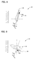
- the situation in step 614 is shown with more detail in Figs. 8 and 9 for a rotating rotor blade and in Figs. 10 and 11 for a non-rotating rotor blade.
- angle of attack ⁇ is defined as an angle between chord line 26 and a velocity vector v rel representing a relative motion between rotor blade 16 and inflow.
- Figs. 8 and 9 for a rotating rotor blade
- Figs. 10 and 11 for a non-rotating rotor blade.
- angle of attack ⁇ is defined as an angle between chord line 26 and a velocity vector v rel representing a relative motion between rotor blade 16 and inflow.
- vector v rel equals an ambient wind vector in direction and magnitude.
- the relative wind velocity v rel is determined as a vector sum of V ⁇ being the ambient wind speed vector and the rotational speed vector v x of rotor blade 16.
- rotational velocities of rotor blades 16 may be larger than typical wind speeds.
- This vector sum is done graphically within Figs. 8 and 9 .
- actual angle of attack ⁇ is chosen in q range between about 18° and about 330°. In this range, air is forced to flow or pulled 616 into apertures 102.
- Figures 9 and 11 show situations where actual angle of attack ⁇ is about 270°. In these situations, air is forced to flow or is pulled 616 into apertures 102. This can be seen very easily for the case of a non-rotating rotor blade 16 because, in that case, wind blows directly into apertures 102 on the suction side of rotor blade 16, as depicted in Fig. 11 .
- Fig. 9 shows the case for a rotating rotor blade.
- actual angle of attack ⁇ is in the range between about 18° and about 330°. In this range, air is forced to flow or is pulled 616 into apertures 102.
- Figs. 8 and 10 show situations for a rotating rotor blade and a non-rotating rotor blade, respectively, when an outward, i.e. downstream, gas flow is promoted.
- angle of attack ⁇ is set to a value smaller than a stall angle.
- the stall angle is defined as an angle at which stalling of a section of rotor blade 16, i.e. complete flow separation, occurs.
- step 618 ending of the rain shower may be awaited in step 618.
- step 620 a rotational speed of wind turbine 10 is increased in step 620.
- steps 618 and/or 620 are optional and either or both step may be omitted.
- method 600 continues with combined or alternative steps 622 and 624.
- This means the next step of method 600 may be step 622 or step 624 or a combination of both applied simultaneously or sequentially.
- both steps 622 and 624 are executed simultaneously or consecutively in order to amplify their effect.
- step 622 the gas flow direction of AFC system 100 is again reversed and set to the downstream direction.
- the gas flows from gas supply 106 to apertures 102. This promotes gas to flow out of apertures 102.
- the pitch angles of rotor blades 16 may be adjusted such that actual angle of attack ⁇ is smaller than a stall angle, i.e. an angle of attack where stalling occurs.
- Figs. 8 and 10 show situations where actual angle of attack ⁇ is smaller than the stall angle for the case of a rotating rotor blade and a non-rotating rotor blade, respectively.
- rotor blade 16 At the stall angle, rotor blade 16 has maximum lift. If actual angle of attack ⁇ becomes larger than the stall angle, wind turbine 10 generates less power and the unsteadiness in the aerodynamic response of a given airfoil is increased. Both effects are undesirable.
- angle of attack ⁇ is smaller than the stall angle, the flow at the given blade section is substantially attached. As the position of apertures 102 is on the suction side after the chord-wise location of maximum airfoil thickness of rotor blade 16, the gas flow out of apertures 102 will be promoted.
- the rain water together with the contaminants, e.g. insects or dirt, contained within manifolds 104 and apertures 102 are blown out due to the gas flow.
- the contaminants e.g. insects or dirt
- manifolds 104 and/or apertures 102 of AFC system 100 are cleaned thus reducing fouling of AFC system 100.
- the operation of wind turbine 10 continues with step 208 or returns to step 602.
- Various of the technical effects of the systems and methods described herein includes at least one of: (a) operating a wind turbine in a first mode; (b) determining an environmental condition surrounding a wind turbine indicative of fouling of an AFC system; (c) operating a wind turbine in a second mode different than a first mode based on an environmental condition, wherein the second mode facilitates reducing fouling of an AFC system; (d) determining an environmental condition surrounding a wind turbine indicative of precipitation; and (e) adjusting at least one of a pitch angle and an azimuth angle of at least one rotor blade such that at least one aperture is wetted.
Landscapes
- Engineering & Computer Science (AREA)
- Life Sciences & Earth Sciences (AREA)
- Sustainable Development (AREA)
- Sustainable Energy (AREA)
- Chemical & Material Sciences (AREA)
- Combustion & Propulsion (AREA)
- Mechanical Engineering (AREA)
- General Engineering & Computer Science (AREA)
- Physics & Mathematics (AREA)
- Fluid Mechanics (AREA)
- Wind Motors (AREA)
Abstract
Description
- The present disclosure relates generally to methods of operating a wind turbine with reduced fouling, particularly to wind turbines having an active flow control (AFC) system, and a wind turbine including such AFC system.
- Although horizontal axis wind turbines are well-established these days, there is still considerable engineering effort going on to further improve their overall efficiency, robustness, and power generating capability.
- This research has lead to the most recent AFC technologies which aim to improve wind turbine efficiency. AFC technologies try to avoid flow separation over rotor blades by actively modifying the wind flow proximate to the rotor blade. This can be achieved by ejecting gas through apertures formed in the surface of the rotor blade.
- The introduction of such AFC systems has brought about the fact that the apertures used for blowing gas eventually collect dirt or impurities. This phenomenon is one aspect of what is referred to as blade fouling. Blade fouling can substantially lower the performance, in particular the extracted power of wind turbines.
- In one aspect according to the present invention, a method of operating a wind turbine is provided. The wind turbine has at least one rotor blade and an active flow control (AFC) system. The at least one rotor blade has at least one aperture defined through a surface thereof, and the AFC system is configured to modify aerodynamic properties of the at least one rotor blade by ejecting gas through the at least one aperture. The method includes operating the wind turbine in a first mode, determining an environmental condition surrounding the wind turbine indicative of fouling of the AFC system, and operating the wind turbine in a second mode different than the first mode based on the environmental condition. The second mode facilitates reducing fouling of the AFC system.
- In another aspect, a method of operating a wind turbine is provided. The wind turbine has at least one rotor blade and an active flow control (AFC) system. The at least one rotor blade includes at least one aperture defined through a surface of the at least one rotor blade, and the AFC system is configured to modify aerodynamic properties of the at least one rotor blade. The method includes determining an environmental condition surrounding the wind turbine indicative of precipitation, and adjusting at least one of a pitch angle and an azimuth angle of the at least one rotor blade such that the at least one aperture is wetted.
- In yet another aspect, a wind turbine is provided. The wind turbine includes at least one rotor blade and an active flow control (AFC) system at least partially defined in the at least one rotor blade. The AFC system is configured to modify aerodynamic properties of the at least one rotor blade. The wind turbine further includes a sensor configured to measure an environmental condition surrounding the wind turbine, and a wind turbine controller. The wind turbine controller is configured to operate the wind turbine in a first mode, and operate the wind turbine in a second mode different than the first mode depending on the environmental condition. The second mode includes adjusting at least one operation parameter of the wind turbine such that fouling of the AFC system is reduced.
- Various aspects, advantages and features of the embodiments described herein are apparent from the dependent claims, the description, and the accompanying drawings.
-
Fig. 1 is a schematic side view of an exemplary wind turbine. -
Fig. 2 is a chord-wise cross sectional view of an exemplary rotor blade that may be used with the wind turbine shown inFig. 1 . -
Fig. 3 is a flowchart of an exemplary method for operating the wind turbine shown inFig. 1 . -
Fig. 4 is a flowchart of a first alternative method for operating the wind turbine shown in -
Fig. 1 . -
Fig. 5 is a flowchart of a second alternative method for operating the wind turbine shown inFig. 1 . -
Fig. 6 is a flowchart of a third alternative method for operating the wind turbine shown inFig. 1 . -
Fig. 7 is a flowchart of a fourth alternative method for operating the wind turbine shown inFig. 1 . -
Fig. 8 is a schematic view of the rotor blade shown inFig. 2 during performance of the method shown inFig. 7 as coupled to a rotating rotor. -
Fig. 9 is a schematic view of the rotor blade shown inFig. 2 during performance of the method shown inFig. 7 as coupled to a rotating rotor. -
Fig. 10 is a schematic view of the rotor blade shown inFig. 2 during performance of the method shown inFig. 7 as coupled to a non-rotating rotor. -
Fig. 11 is a schematic view of the rotor blade shown inFig. 2 during performance of the method shown inFig. 7 as coupled to a non-rotating rotor. - Reference will now be made in detail to the various embodiments, one or more examples of which are illustrated in each figure. Each example is provided by way of explanation and is not meant as a limitation. For example, features illustrated or described as part of one embodiment can be used on or in conjunction with other embodiments to yield yet further embodiments. It is intended that the present disclosure includes such modifications and variations.
- Modem wind turbines are designed to produce a maximum amount of energy. However, if the wind speed becomes too large and therefore changes an angle of attack above a certain value, flow separation over wind turbine blades occurs and results in stall. In such a situation, energy production by the turbine is reduced. If he flow separation over wind turbine blades can be delayed, the design of the wind turbine can be favorably changed, e.g. to increase the production of energy across the wind speed range and/or to change design parameters such as chord. This will eventually result in a considerable increase of wind turbine energy production.
- Flow separation over wind turbine blades can be delayed by blowing gas out of small apertures arranged at the surface of the rotor blade. The gas may be fed to the apertures through manifolds within the rotor blade by a gas supply. Various gases may be used, such as, but not limited to air, nitrogen, or carbon dioxide. In the following, the term "air" will be exemplarily used without any intention to limit the scope of the appended claims. The gas flow rate through the manifolds and out of the apertures is controlled by the gas supply. Controlling the gas flow rate results in delayed flow separation, which changes the aerodynamic properties of the rotor blade. The system, including a gas supply, manifolds, and apertures, actively controls a gas flow out of the apertures of the rotor blade. This system is referred to as an active flow control (AFC) system.
- Although the embodiments described herein are illustrated with respect to a nonzero-net-mass flow control system, it should be understood that the systems and methods described herein can also be used with a zero-net-mass flow control system.
-
Fig. 1 shows anexemplary wind turbine 10 having anAFC system 100, asensor 12, and awind turbine controller 14.Fig. 2 shows a chord-wise cross-sectional view of arotor blade 16 being equipped withAFC system 100. As shown inFig. 1 ,wind turbine 10 includes threerotor blades 16, however,wind turbine 10 may include more or less than threerotor blades 16.Rotor blades 16 are mounted on arotor hub 18 that is connected to anacelle 20 fixed on top of atower 22.Fig. 2 shows a position ofAFC apertures 102 ofrotor blade 16. InFig. 2 ,rotor blade 16 is seen along a span-wise axis ofrotor blade 16. In typical situations, awind direction 24impinges rotor blade 16 at an area slightly above where achord line 26 intersectsrotor blade 16 at a leadingedge 28 ofrotor blade 16. - Aerodynamic properties of
rotor blade 16 are changed by gas being ejected throughapertures 102 defined through asurface 30 ofrotor blade 16 on its suction side.Apertures 102 are typically positioned on the suction side ofrotor blade 16 downwind of the airfoil maximum thickness. InFig. 2 the suction side is an upper side ofrotor blade 16. According to other embodiments,apertures 102 are positioned on a rotor blade section where flow separation mainly occurs. - According to embodiments disclosed herein, blade fouling of
wind turbine 10, and especially fouling ofapertures 102 andmanifolds 104 included insiderotor blade 16, is avoided, or at least reduced, by operating wind turbine in a preventive manner such thatAFC system 100, and especially manifolds 104 andapertures 102 ofAFC system 100 collect less contamination or are not subject to contaminants in the first place. - In the embodiment shown in
Fig. 1 , eachrotor blade 16 includes at least onemanifold 104. At a downstream end,manifold 104 is connected to at least oneaperture 102 atsurface 30 ofrotor blade 16. For reasons of simplicity, only onerotor blade 16 with only onemanifold 104 and oneaperture 102 is depicted. However, a plurality ofmanifolds 104, typically of different lengths, can be provided withinrotor blade 16. Furthermore, each manifold 104 is connected to a plurality ofapertures 102. Although depicted only for onerotor blade 16, theother rotor blades 16 includemanifolds 104 andapertures 102. At an upstream end,manifold 104 is connected to agas supply 106 from which gas is supplied tomanifold 104. In this context, the terms "upstream" and "downstream" refer to gas flow directions withinAFC system 100. In particular, the downstream direction is defined to be fromgas supply 106 toaperture 102. The downstream direction is a direction of gas flow during an AFC mode in which gas is ejected throughapertures 102 ofrotor blades 16 in order to improve the aerodynamic properties ofrotor blade 16. On the other hand, the upstream direction is defined as a direction fromapertures 102 towardsgas supply 106. In the embodiment shown inFig. 1 ,gas supply 106 is located insidenacelle 20. According to other embodiments,gas supply 106 may also be located insidetower 22, insiderotor hub 18, and/orinside rotor blade 16. According to alternative embodiments, there is provided onegas supply 106 for eachrotor blade 16. According to some of these embodiments, in eachrotor blade 16 there is provided onegas supply 106. - According to the embodiment of
Fig. 1 , each manifold 104 is configured to channel gas and is connected to avalve 108. Eachvalve 108 is configured to block a gas flow to arespective manifold 104 and is positioned withinnacelle 20 ofwind turbine 10. Eachvalve 108 may be continuously adjusted from completely open to completely closed. It is to be understood that the term "blocking" does not necessarily mean complete blocking, I but may also imply partial blocking ofmanifolds 104.Valves 108 may thus have a flow control function. Ifvalve 108 is not closed completely, the gas flow through the remainingvalves 108 is not increased to the same extent as compared to the case whenvalve 108 closes completely. According to some embodiments,valves 108 may be replaced by other flow control devices which are configured to control gas flows ofmanifolds 104. According to other embodiments,valves 108 may also be positioned insiderotor hub 18, inside arotor blade 16, or insidetower 22. The latter arrangement may be used whengas supply 106 is located insidetower 22.Manifolds 104 ofrotor blades 16 are typically connected in parallel togas supply 106 and may be blocked by theirrespective valves 108. AnAFC controller 110, which may be included in or separate fromwind turbine controller 14,controls valves 108 andgas supply 106. This control is indicated by arrows inFig. 1 . The foregoing is merely exemplary and should not be construed as limiting because the present application also encompasses embodiments withoutvalves 108. - A gas flow rate through
manifolds 104 is controlled byAFC controller 110. According to one embodiment,AFC controller 110 controls the gas flow rate throughmanifolds 104 by changing the gas flow rate ofgas supply 106. According to a further embodiment,AFC controller 110 controls the gas flow rate throughmanifolds 104 by blocking,e.g. manifold 104, thereby increasing the gas flow rate through the unblockedmanifolds 104. Thus, an ejection pattern of ejected air is altered and the aerodynamic properties ofrotor blade 16 are varied. For blockingmanifolds 104,AFC controller 110 may usevalves 108. Eachvalve 108 may be continuously adjusted from completely open to completely closed, blocking the gas flow in the latter case.AFC controller 110 is part ofAFC system 100, which includesmanifolds 104,apertures 102,air supply 106, andvalves 108. According to the embodiments described above,AFC system 100, particularlyAFC controller 110, are configured to modify the aerodynamic properties ofrotor blades 16 which typically results in delaying a flow separation overrotor blades 16. - In the embodiment shown in
Fig. 1 ,wind turbine controller 14controls AFC controller 110,gas supply 106, and apitch controller 32. According to further embodiments,wind turbine controller 14 further controls a yaw angle and/or a generator speed. Generally,wind turbine controller 14 is configured to adjust at least one operation parameter ofwind turbine 10 based on an environmental condition measured bysensor 12 such that fouling ofAFC system 100 is reduced. According to the embodiment shown inFig. 1 ,AFC controller 110controls gas supply 106, whilewind turbine controller 14controls AFC controller 110. According to other embodiments,wind turbine controller 14controls gas supply 106. Generally,wind turbine controller 14 may control any operation parameter ofwind turbine 10. Operation parameters includes, but are not limited to including, a rotational speed, a pitch angle ofrotor blades 16, a yaw angle, and/or a gas flow rate throughAFC system 100, in particular throughgas supply 106. -
Sensor 12 is configured to measure an environmental condition surroundingwind turbine 10. The environmental condition is indicative of fouling ofAFC system 100. The environmental condition is processed bywind turbine controller 14 to determine how to operatewind turbine 10. Although depicted atnacelle 20,sensor 12 may also be located in or attower 22, insiderotor hub 18, insiderotor blade 16, and/or away fromwind turbine 10. For example,sensor 12 may be a weather station installed nearwind turbine 10 or at least near a wind farm in whichwind turbine 10 is located. - The environmental condition includes, without limitation, an air humidity, a wind speed, an air temperature, an aerosol concentration, an airborne particle concentration, an airborne contaminants concentration, a concentration of any sort of flora, fauna, and/or any by-products thereof (e.g. fluff), a wind direction, a rain direction, a frequency of wind gusts, an atmospheric pressure, a wind chill factor, a cloud height, a cloud cover, a visibility, a dew point, a migration of birds and/or other animals, and/or a frequency and/or an amount of animal excrement, in particular bird droppings. Furthermore, any combination of two or more of the foregoing environmental conditions may be used to determine whether an increased risk for AFC fouling exists.
-
Fig. 3 illustrates anexemplary method 200 of operating wind turbine 10 (shown inFig. 1 ). By performingmethod 200, fouling of rotor blade 16 (shown inFigs. 1 and2 ) and/or AFC system 100 (shown inFig. 1 ) is facilitated to be corrected and/or prevented.Method 200 is performed by wind turbine controller 14 (shown inFig. 1 ) and/or AFC controller 110 (shown inFig. 1 ) sending commands and/or instructions to components ofwind turbine 10, such asAFC system 100 and/or any suitable component.Wind turbine controller 14 and/orAFC controller 110 is programmed with code segments configured to performmethod 200. Alternatively,method 200 is encoded on a computer-readable medium that is readable bywind turbine controller 14 and/orAFC controller 110. In such an embodiment,wind turbine controller 14 and/orAFC controller 110 is configured to read computer-readable medium for performingmethod 200. - Referring to
Figs. 1-3 ,method 200 includes operating 202wind turbine 10 in a first mode, such as a normal mode. The term "normal mode" refers to a mode of operatingwind turbine 10 and/orAFC system 100 such that AFC system 100 a drives a flow of fluid to increase lift on at least onerotor blade 16. The normal mode includes normal operation over a substantially entire power curve; operating when a wind speed is too low to generate power butwind turbine 10 is prepared to generate power; using constant and variable speed-ranges; operating within a peak shaver range; operating in an above rated condition; and/or performing a storm cut out. Flow characteristics of the fluid flow during the normal mode are determined empirically and/or are predetermined to achieve optimal lift onrotor blade 16 depending on ambient conditions, such as a wind speed and/or a wind direction, precipitation, and/or other atmospheric and/or environmental conditions. At least one flow characteristic of the fluid flow may be adjusted and/or varied during the normal mode, based on changing ambient conditions and/or operating characteristics ofwind turbine 10, to facilitate achieving optimal blade lift. -
Wind turbine 10 and/orAFC system 100 is operated 202 in the normal mode according to a predetermined schedule and/or based on wind conditions. For example, when wind speeds are high,operation 202 ofAFC system 100 is substantially terminated because increased lift onrotor blade 16 is not desired in such wind conditions. However, even when active flow control is terminated, enough fluid is discharged fromapertures 102 to facilitate preventing insects and/or other debris from flying intomanifolds 104. Such termination of active flow control is considered to be part of the normal operating mode. - As
wind turbine 10 is operating 202 in the normal mode,wind turbine 10 determines 204 at least one environmental condition surroundingwind turbine 10. More specifically,wind turbine 10 collectsdata using sensor 12 and processes the data to determine 204 the environmental condition. Based on the environmental condition, it is determined 206 whether to operatewind turbine 10 in the normal mode or in a second mode, such as a cleaning mode. As used herein, the term "second mode" refers to a mode of operatingwind turbine 10 and/orAFC system 100 to achieve an outcome in addition to or different than optimal lift onrotor blade 16. As used herein, the term "optimal lift" refers to lift that maximizes power production and reduces the cost of power production, such as a lift that is optimized to account for initial costs ofwind turbine 10 and/or a lift that produces a maximized ratio of annual energy capture over initial cost; however, any suitable optimization scheme can be used to achieve optimal lift. It should be understood thatwind turbine 10 can be operated in more than two modes. In the exemplary embodiment, the second mode is a mode that is intentionally beneficial for performing a cleaning operation rather than performing an operation target, such as capturing energy. During the second mode,AFC system 100 is controlled to facilitate removing debris fromAFC system 100. The second mode includes at least one cleaning mode to facilitate removing debris fromAFC system 100. - By comparing the environmental condition with certain criteria, it is determined 206 whether to operate
wind turbine 10 in the normal mode or in the second mode. If it is determined 206 to operate in the first mode,wind turbine 10 continues performingsteps wind turbine 10 switches from the first mode to operate 208 in the second mode. Based on a time period, an operator's command, sensed environmental conditions, and/or any other suitable criteria,wind turbine 10 operates 208 in the second mode then returns to operating 202 in the first mode. -
Fig. 4 is a flowchart of afirst example method 300 for operating wind turbine 10 (shown inFig. 1 ).Method 300 includes at least some of the steps of method 200 (shown inFig. 3 ) and, as such, similar steps are indicated with similar reference numbers. Referring toFigs. 1 ,2 , and4 , whilewind turbine 10 is operating 302 in the first mode,method 300 starts by determining 204 an environmental condition ofwind turbine 10 indicative of fouling ofAFC system 100 by sensing 304 an environmentalcondition using sensor 12. At least one sensed environmental condition is used to determine 306 specific values that indicate a higher risk of fouling ofAFC system 100 ofwind turbine 10. More specifically, estimated insect density and/or aerosol concentration are determined 306 from the sensed environmental condition. - For example, insect density, concentration of dust, impurities, or aerosols or the like are typical indicators that an elevated risk of AFC fouling exists. For example, on days with specific weather conditions, flying insects are likely to fly in the air next to
wind turbine 10. Such flying insects may entermanifolds 104 ofAFC system 100 viaapertures 102, thus cloggingmanifolds 104 andapertures 102. Similarly, fouling ofAFC system 100 is more likely when there is a high concentration of dust particles or aerosols in the ambient air. Such conditions are detected 304 bysensor 12 either directly or indirectly. For example, empirical knowledge or theoretical considerations may connect certain weather conditions with high insect activity or high aerosol concentration. Therefore, a higher aerosol concentration may be indirectly determined 306 from the actual weather conditions. - According to another example, sensed environmental conditions can be used to determine 306 insect density. Certain species of insects prefer to fly in conditions of high air humidity, low winds, and temperatures above 10 °C. If all those conditions are fulfilled, probability is high that
apertures 102 may be clogged by those insects. - The estimated insect density value and/or the estimated aerosol concentration value are determined 306 based on a state of the environmental condition sensed in
step 304. According to further embodiments, additionally or alternatively to the estimated insect density value and/or the estimated aerosol concentration value, at least one of the above mentioned environmental conditions is used inmethod 300. - It is decided 308 whether the estimated insect density value and/or the estimated aerosol concentration value is larger than a respective threshold value. The threshold value need not be constant for a different environmental condition. The threshold value rather may be a complex function of various parameters, e.g. air humidity, air temperature, and/or other variables. In a particular embodiment, a typical value for the insect density threshold is in a range between about 0.003 m-3 and about 0.01 m-3, and an aerosol concentration threshold value is approximately equal to 10 µg• m-3. According to some embodiments, the threshold function is influenced by which part of a power
curve wind turbine 10 is running, a history of fouling-reduction actions, and/or a history of the environmental condition, e.g. last couple of weeks or years. According to yet further embodiments, instead of the above mentionedstep 308, a decision making process is implemented. In this decision making process, it is decided whether or not the detected environmental condition, in particular the measured insect density or aerosol density, makes it necessary to switch to the second mode, such as a foul ing-reducing mode. - In the exemplary embodiment, if neither the estimated insect density value nor the estimated aerosol concentration value is larger than its respective threshold value, operation of
wind turbine 10 is not changed from the first mode to the second mode. More specifically, in the exemplary embodiment, the operation parameters ofwind turbine 10 are not changed based on the environmental conditions, andmethod 300 returns to step 302 to continue monitoring of the environmental condition surroundingwind turbine 10. It will be understood by those skilled in the art that any operation parameter may be adjusted based on considerations other than AFC fouling. In this context, energy yield and/or turbine loads are the most prominent consideration so that operation parameters, e.g. pitch angle, may be adjusted in order to increase the energy yield of the turbine. On the other hand, safety considerations must be observed so that very high wind speeds or faults in the electrical subsystem may cause a turbine shutdown without any insect bloom or dust in the air. Whether energy yield, safety requirements, fouling prevention or any other consideration prevails in a certain situation will be determined on the exact circumstances of this situation. - In
step 308, in the event that the estimated insect density value and/or the estimated aerosol concentration value is larger than its respective threshold value, operation ofwind turbine 10 is changed from the first mode to the second mode. More specifically, in the exemplary embodiment, the second mode includes increasing 310 the gas flow ofAFC system 100 for blowing insects or impurities out ofrotor blade 16 throughapertures 102 and/or for preventing insects or impurities from enteringrotor blade 16 throughapertures 102. By blowing insects or impurities out ofrotor blade 16 throughapertures 102,AFC system 100 is cleaned, whereas by preventing insects or impurities from enteringrotor blade 16 throughapertures 102,AFC system 100 is prevented from fouling. By increasing 310 the gas flow throughAFC system 100, clogging ofapertures 102 ofAFC system 100 by insects, aerosols, impurities, dust particles, dirt, and/or the like is prevented or at least reduced. Furthermore, not onlyapertures 102, but also manifolds 104, may be cleaned by increasing 310 the gas flow throughAFC system 100. In this context, it is to be noted that cleaning is typically applied whenwind turbine 10 is not producing power, whereas fouling prevention could be applied all the time and/or when demanded by the environmental condition. - After
step 310, the cleaning ofAFC system 100 ends and operation ofwind turbine 10returns 302 to the first mode. Typically,wind turbine 10 will continue to monitor 204 the environmental condition by returning to step 302. According to a further embodiment, an operator may choose to continue withstep 302, to endmethod 300, and/or to continue with a different method. -
Fig. 5 is a flowchart of asecond example method 400 for operating wind turbine 10 (shown inFig. 1 ).Method 400 includes at least some of the steps of method 200 (shown inFig. 3 ) and, as such, similar steps are indicated with similar reference numbers. Referring toFigs. 1 ,2 , and5 , whilewind turbine 10 is operating 402 in the first mode,method 400 includes determining 204 an environmental condition surroundingwind turbine 10 indicative of fouling ofAFC system 100. In general,wind turbine 10 is operated such that, based on the detected environmental condition, fouling ofAFC system 100 is reduced. - To determine 204 the environmental condition, at least one environmental condition is measured and/or sensed 404 by
sensor 12. The measured or sensed value is then processed to determine 406 an estimated insect density value and/or an estimated aerosol concentration value. - In
step 408, it is then decided whether the estimated insect density value and/or the estimated aerosol concentration value is larger than its respective threshold value. The threshold value need not be constant for a different environmental condition. The threshold value rather may be a complex function of various parameters, e.g. air humidity, air temperature, and/or other variables. According to some embodiments, the threshold function is influenced by which part of a powercurve wind turbine 10 is running, a history of fouling-reduction actions, and/or a history of the environmental condition, e.g. last couple of weeks or years. According to yet further embodiments, instead of thestep 408, a decision making process is implemented. In this decision making process, it is decided whether or not the detected environmental condition, in particular the measured insect density or aerosol density, makes it necessary to switch to the second mode, such as a fouling-reducing mode. - In the exemplary embodiment, if neither the estimated insect density value nor the estimated aerosol concentration value is larger than its respective threshold value,
wind turbine 10 continues operating 402 in the first mode. More specifically, the operation parameters ofwind turbine 10 are not changed, andmethod 400 returns to step 402 to continue monitoring the environmental condition surroundingwind turbine 10. As explained above, considerations other than AFC fouling may result in adjusting the operational parameters. - In the event that the estimated insect density value or the estimated aerosol concentration value is larger than its respective threshold value, operation of
wind turbine 10 is changed from the first mode to the second mode, andwind turbine 10 operates 410 in the second mode for some time. More specifically, in the exemplary embodiment, the second mode includes shutting down 410wind turbine 10. According to some embodiments, when shutting down 410wind turbine 10,rotor blades 10 may be pitched to a feathered position to avoid insects hitting a region of blade surface30 wheremanifolds 104 and/orapertures 102 are located. - After
step 410, an operator orwind turbine controller 14 may restartwind turbine 10 to operate 402 in the first mode at some point when both the insect concentration and the aerosol concentration have dropped below their respective threshold values. To this end, the environmental conditions may be further monitored whilewind turbine 10 is shut down 410. The operator may also have the option to continue with another method of operatingwind turbine 10. -
Fig. 6 is a flowchart of asecond example method 500 for operating wind turbine 10 (shown inFig. 1 ).Method 500 includes at least some of the steps of method 200 (shown inFig. 3 ) and, as such, similar steps are indicated with similar reference numbers. Referring toFigs. 1 ,2 , and6 , whilewind turbine 10 is operating 502 in the first mode,method 500 includes determining 504 environmental conditions, such as a presence of precipitation, usingsensor 12. Based on data collected bysensor 12,wind turbine 10 determines 506 whether or not it is precipitating at the respective moment. In the event it is not precipitating,steps method 500 only continues to execute operations in case precipitation is detected.Method 500 is described with respect to detecting rain, however it should be understood thatmethod 500 may be performed with any suitable precipitation. - In the event a rain shower is detected in
step 506,method 500 includes operating 208wind turbine 10 in the second mode rather than the first mode. More specifically, when it is determined 506 that it is raining,method 500 continues to step 508 where pitch angles ofrotor blades 16, an azimuth angle ofrotor blade 16, and/or a rotor blade rotational speed are adjusted such thatapertures 102 ofAFC system 100 are wetted by the rain. To this end,rotor blades 16 are rotated such thatapertures 102 face a rain direction relative torotor blades 16. In this connection, "facing" means that an angle between a surface normal ofaperture 102 and the rain direction is smaller than about 90°. In other words,rotor blades 16 are positioned such that rain impinges ontorotor blade surface 30 in an area whereapertures 102 are located. Typicallyapertures 102 face a similar direction so that the technical meaning of the above is easily understood by a person skilled in the art. - In the exemplary embodiment, after wetting of
apertures 102, the rain water is pulled 510 intorotor blades 16, more particularly intomanifolds 104 formed withinrotor blades 16, throughapertures 102. This is typically accomplished by reversing a gas flow direction ofAFC system 100 to the upstream direction. In other words, the gas flows intoapertures 102 and towardsgas supply 106. As described above, this may, for example, be achieved by reversing a pumping direction and/or a rotation direction of a fan or similar device. To further increase the reverse gas flow, in some embodiments, a pitch angle of eachrotor blade 16 is adjusted such that a static pressure atapertures 102 is increased to force air to flow intoapertures 102. Generally, before this is done, the AFC mode is stopped or, even better, an inward gas flow intoapertures 102 is initiated. Thus, the reversed operation ofAFC gas supply 106 and the static pressure cooperate in order to increase the gas flow intoapertures 102. According to other embodiments, instead of actively pulling 510 water intorotor blade 16 throughapertures 102, water entersapertures 102 andmanifolds 104 due to gravity, cavitation, and/or capillary forces. - In
step 512, the rain water and impurities withinmanifolds 104 andapertures 102 are blown out ofrotor blade 16. To this end, the gas flow direction ofAFC system 100 is again reversed to a downstream flow in which the gas flows fromgas supply 106 towardsapertures 102. In some embodiments, this downstream gas flow is assisted by adjusting the pitch angle of eachrotor blade 16 and/or an azimuth angle ofrotor blade 16 such that a dynamic pressure atapertures 102 is increased to pull the gas out ofapertures 102. By blowing rain water and impurities out ofrotor blade 16,manifolds 104 andapertures 102 are cleaned and, thus, fouling ofAFC system 100 is reduced. After cleaning ofrotor blades 16,method 500 may continue atstep 208, or may return to step 502. -
Fig. 7 is a flowchart of asecond example method 600 for operating wind turbine 10 (shown inFig. 1 ).Method 600 includes at least some of the steps of method 200 (shown inFig. 3 ) and, as such, similar steps are indicated with similar reference numbers. Referring toFigs. 1 ,2 , and7 , whilewind turbine 10 is operating 602 in the first mode,method 600 includes determining 604 environmental conditions, such as a presence of precipitation, usingsensor 12. Based on data collected bysensor 12,wind turbine 10 determines 606 whether or not it is precipitating, such as raining, at the respective moment. These detection steps 604 and 606 are looped until precipitation is detected. Thusmethod 600 only continues to execute operations in case of precipitation.Method 600 is described below with respect to detecting rain, however it should be understood thatmethod 600 may be performed with any suitable precipitation. - In the event of a rain shower,
method 600 includes operating 208wind turbine 10 in the second mode rather than the first mode. More specifically, in the exemplary embodiment,method 600 continues to step 608 where pitch angles ofrotor blades 16, an azimuth angle ofrotor blade 16, and/or a rotor blade rotational speed are adjusted such thatapertures 102 are wetted. To this end,rotor blades 16 are rotated such thatapertures 102 face a rain direction. According to other embodiments,rotor blades 16 are rotated such thatapertures 102 face the wind direction. - In the exemplary embodiment, after
step 608,wind turbine 10 is operated 610 at such a low rotational speed that spinning off of water fromrotor blades 16 is reduced. Typically, forwind turbine 10 having blade lengths of about 50 meters, and a tower height of about 16 meters, this happens at a rotational speed between about 5 rotations per minute (rpm) and about 15 rpm. Thus, more rain water remains onrotor blades 16 and is available for dissolving and/or suspending contaminants and/or for rinsingapertures 102 andmanifolds 104 ofAFC system 100. - The next step of the method may be step 612 or step 614 or a combination of both applied simultaneously or sequentially. In
step 612, a gas flow direction ofgas supply 106 is reversed with respect to a direction of gas flow during an AFC mode. In other words, the gas flow direction is now upstream so that air and water at ornear apertures 102 are pulled 616 intorotor blade 16 fromblade surface 30. Thus,apertures 102 and/ormanifolds 104 ofAFC system 100 are rinsed with rain water. - In the exemplary embodiment, in particular,
AFC controller 110 andgas supply 106 are configured to reverse 612 the gas flow direction. In other words,AFC system 100 is configured to switch to an upstream gas flow, in contrast to the downstream gas flow during the AFC mode. For example, this may be achieved by reversing 612 the pumping direction ifgas supply 106 includes a pump, or by reversing 612 the rotational direction ifgas supply 106 includes a fan or similar device. It will be understood by those skilled in the art that the foregoing is only meant as non-limiting examples. - To assist this reversed gas flow, a pitch angle of
rotor blades 16 may be adjusted 614 such that an actual angle of attack α is about 270°. In some embodiments, especially where the gas flow direction ofgas supply 106 cannot be reversed,step 614 is applied alternatively to step 375. The situation instep 614 is shown with more detail inFigs. 8 and 9 for a rotating rotor blade and inFigs. 10 and 11 for a non-rotating rotor blade. Therein, angle of attack α is defined as an angle betweenchord line 26 and a velocity vector vrel representing a relative motion betweenrotor blade 16 and inflow. For the non-rotating rotor blade shown inFigs. 10 and 11 , vector vrel equals an ambient wind vector in direction and magnitude. For a rotating rotor blade, which case is depicted inFigs. 8 and 9 , the relative wind velocity vrel is determined as a vector sum of V∞ being the ambient wind speed vector and the rotational speed vector vx ofrotor blade 16. In this context, it is observed that rotational velocities ofrotor blades 16 may be larger than typical wind speeds. This vector sum is done graphically withinFigs. 8 and 9 . According to other embodiments, instep 614, actual angle of attack α is chosen in q range between about 18° and about 330°. In this range, air is forced to flow or pulled 616 intoapertures 102. -
Figures 9 and11 show situations where actual angle of attack α is about 270°. In these situations, air is forced to flow or is pulled 616 intoapertures 102. This can be seen very easily for the case of anon-rotating rotor blade 16 because, in that case, wind blows directly intoapertures 102 on the suction side ofrotor blade 16, as depicted inFig. 11 .Fig. 9 shows the case for a rotating rotor blade. According to other embodiments, actual angle of attack α is in the range between about 18° and about 330°. In this range, air is forced to flow or is pulled 616 intoapertures 102. - On the other hand,
Figs. 8 and10 show situations for a rotating rotor blade and a non-rotating rotor blade, respectively, when an outward, i.e. downstream, gas flow is promoted. In this event, angle of attack α is set to a value smaller than a stall angle. The stall angle is defined as an angle at which stalling of a section ofrotor blade 16, i.e. complete flow separation, occurs. - Referring again to
Fig. 7 , after reversing the gas flow direction insteps manifolds 104 throughapertures 102. In the following,apertures 102 and/ormanifolds 104 ofAFC system 100 are rinsed with the rain water. After the rain water has dissolved and loosened the impurities withinapertures 102 andmanifolds 104, the impurities are rinsed or blown out ofrotor blade 16. - To this end, ending of the rain shower may be awaited in
step 618. Subsequently, a rotational speed ofwind turbine 10 is increased instep 620. By increasing 620 the rotational speed ofwind turbine 10, the water and impurities on orinside rotor blade 16 are thrown out or spun offrotor blade 16 thus cleaningrotor blade 16, and inparticular AFC system 100. It will be understood by those skilled in the art steps 618 and/or 620 are optional and either or both step may be omitted. - After the
optional steps method 600 continues with combined oralternative steps method 600 may be step 622 or step 624 or a combination of both applied simultaneously or sequentially. Typically bothsteps - In
step 622, the gas flow direction ofAFC system 100 is again reversed and set to the downstream direction. In that case, the gas flows fromgas supply 106 toapertures 102. This promotes gas to flow out ofapertures 102. To assist this outward gas flow, the pitch angles ofrotor blades 16 may be adjusted such that actual angle of attack α is smaller than a stall angle, i.e. an angle of attack where stalling occurs. -
Figs. 8 and10 show situations where actual angle of attack α is smaller than the stall angle for the case of a rotating rotor blade and a non-rotating rotor blade, respectively. At the stall angle,rotor blade 16 has maximum lift. If actual angle of attack α becomes larger than the stall angle,wind turbine 10 generates less power and the unsteadiness in the aerodynamic response of a given airfoil is increased. Both effects are undesirable. In case angle of attack α is smaller than the stall angle, the flow at the given blade section is substantially attached. As the position ofapertures 102 is on the suction side after the chord-wise location of maximum airfoil thickness ofrotor blade 16, the gas flow out ofapertures 102 will be promoted. - According to
method 600, in thenext step 626, the rain water together with the contaminants, e.g. insects or dirt, contained withinmanifolds 104 andapertures 102 are blown out due to the gas flow. By blowing out 626 rain water and impurities,manifolds 104 and/orapertures 102 ofAFC system 100 are cleaned thus reducing fouling ofAFC system 100. After rain water is blown out 626 ofrotor blade 16, the operation ofwind turbine 10 continues withstep 208 or returns to step 602. - Various of the technical effects of the systems and methods described herein includes at least one of: (a) operating a wind turbine in a first mode; (b) determining an environmental condition surrounding a wind turbine indicative of fouling of an AFC system; (c) operating a wind turbine in a second mode different than a first mode based on an environmental condition, wherein the second mode facilitates reducing fouling of an AFC system; (d) determining an environmental condition surrounding a wind turbine indicative of precipitation; and (e) adjusting at least one of a pitch angle and an azimuth angle of at least one rotor blade such that at least one aperture is wetted.
- This written description uses examples, including the preferred mode, to enable any person skilled in the art to make and use the described subject-matter. While various specific embodiments have been disclosed in the foregoing, those skilled in the art will recognize that the spirit and scope of the claims allows for equally effective modifications. Especially, mutually non-exclusive features of the embodiments described above may be combined with each other. The patentable scope is defined by the claims, and may include such modifications and other examples that occur to those skilled in the art. Such other examples are intended to be within the scope of the claims if they have structural elements that do not differ from the literal language of the claims, or if they include equivalent structural elements with insubstantial differences from the literal language of the claims.
- Various aspect and embodiments of the present inventions are defined by the following numbered clauses:
- 1. A method of operating a wind turbine having at least one rotor blade and an active flow control (AFC) system, the at least one rotor blade having at least one aperture defined through a surface thereof and the AFC system configured to modify aerodynamic properties of the at least one rotor blade by ejecting gas through the at least one aperture, said method comprising:
- operating the wind turbine in a first mode;
- determining an environmental condition surrounding the wind turbine indicative of fouling of the AFC system; and
- operating the wind turbine in a second mode different than the first mode based on the environmental condition, the second mode facilitating reducing fouling of the AFC system.
- 2. The method according to
clause 1, wherein determining an environmental condition comprising determining at least one of an air humidity, a wind speed, an air temperature, an aerosol concentration, an airborne particle concentration, an airborne contaminants concentration, a wind direction, a rain direction, a frequency of wind gusts, an atmospheric pressure, a wind chill factor, a cloud height, a cloud cover, a visibility, and a dew point. - 3. The method according to any preceding clause, wherein
determining an environmental condition comprises determining whether an estimated insect density value is above an insect density threshold value based on the environmental condition; and
operating the wind turbine in a second mode comprises adjusting at least one operation parameter of the wind turbine based on the estimated insect density value such that clogging of the at least one aperture is reduced. - 4. The method according to any preceding clause, wherein the at least one operation parameter is a gas flow rate of the AFC system, said method further comprising increasing the gas flow rate of the AFC system when the estimated insect density value is larger than an insect density threshold value.
- 5. The method according to any preceding clause, operating the wind turbine in a second mode comprises shutting down the wind turbine when the estimated insect density value is larger than an insect density threshold value.
- 6. The method according to any preceding clause, wherein
determining an environmental condition comprises determining whether an aerosol concentration value is above an aerosol concentration threshold value; and
operating the wind turbine in a second mode comprises increasing a gas flow rate of the AFC system when the aerosol concentration value is larger than an aerosol concentration threshold value. - 7. The method according to any preceding clause, wherein
determining an environmental condition comprises determining whether it is precipitating; and
operating the wind turbine in a second mode comprises positioning the at least one rotor blade such that the at least one aperture is wetted by the precipitation. - 8. The method according to any preceding clause, wherein the positioning comprises at least one of:
- adjusting a pitch angle of the at least one rotor blade; and
- adjusting an azimuth angle of the at least one rotor blade.
- 9. The method according to any preceding clause, wherein the positioning comprises positioning the at least one rotor blade relative to a rain direction such that the at least one aperture faces the rain direction.
- 10. A method of operating a wind turbine having at least one rotor blade and an active flow control (AFC) system, the at least one rotor blade including at least one aperture defined through a surface of the at least one rotor blade and the AFC system configured to modify aerodynamic properties of the at least one rotor blade, said method comprising:
- determining an environmental condition surrounding the wind turbine indicative of precipitation; and
- adjusting at least one of a pitch angle and an azimuth angle of the at least one rotor blade such that the at least one aperture is wetted.
- 11. The method according to any preceding clause, further comprising operating the wind turbine at a rotational speed that prevents the precipitation from spinning off of the at least one rotor blade.
- 12. The method according to any preceding clause, wherein at least one manifold is defined in the at least one rotor blade, said method further comprising:
- initiating an inward gas flow into the at least one manifold through the at least one aperture; and
- adjusting the pitch angle of the at least one rotor blade to increase a static pressure at the at least one aperture to promote air to flow into the at least one aperture.
- 13. The method according to any preceding clause, further comprising adjusting the pitch angle of the at least one rotor blade to reduce a static pressure at the at least one aperture to promote gas to flow out of the at least one aperture.
- 14. The method according to any preceding clause, further comprising adjusting the pitch angle of the at least one rotor blade such that an actual angle of attack of the at least one rotor blade is smaller than a stall angle.
- 15. The method according to any preceding clause, wherein at least one manifold is defined in the at least one rotor blade, said method further comprising:
- initiating an inward gas flow into the at least one manifold; and
- adjusting the pitch angle of the at least one rotor blade such that an actual angle of attack of the at least one rotor blade is about 270 degrees.
- 16. The method according to any preceding clause, further comprising:
- setting a gas flow direction of the AFC system to an upstream gas flow direction; and
- pulling rain water into the at least one aperture.
- 17. The method according to any preceding clause, further comprising:
- after pulling the rain water into the at least one aperture, setting the gas flow direction of the AFC system to a downstream gas flow direction; and
- blowing gas through the at least one aperture to remove the rain water and impurities in the rain water from inside the AFC system.
- 18. A wind turbine comprising:
- at least one rotor blade;
- an active flow control (AFC) system at least partially defined in said at least one rotor blade, said AFC system configured to modify aerodynamic properties of said at least one rotor blade;
- a sensor configured to measure an environmental condition surrounding said wind turbine; and
- a wind turbine controller configured to:
- operate said wind turbine in a first mode; and
- operate said wind turbine in a second mode different than the first mode depending on the environmental condition, the second mode including adjusting at least one operation parameter of said wind turbine such that fouling of said AFC system is reduced.
- 19. The wind turbine according to any preceding clause, wherein said sensor is a rain sensor.
- 20. The wind turbine according to any preceding clause, wherein said AFC system is configured to reverse a gas flow direction through said AFC system.
Claims (10)
- A wind turbine (10) comprising:at least one rotor blade (16);an active flow control (AFC) system (100) at least partially defined in said at least one rotor blade, said AFC system configured to modify aerodynamic properties of said at least one rotor blade;a sensor (12) configured to measure an environmental condition surrounding said wind turbine; anda wind turbine controller (110) configured to:operate said wind turbine in a first mode; andoperate said wind turbine in a second mode different than the first mode depending on the environmental condition, the second mode including adjusting at least one operation parameter of said wind turbine such that fouling of said AFC system is reduced.
- The wind turbine (10) according to claim 1, wherein said sensor (12) is a rain sensor.
- The wind turbine (10) according to any preceding claim, wherein said AFC system (100) is configured to reverse a gas flow direction through said AFC system.
- A method (200) of operating a wind turbine (10) having at least one rotor blade (16) and an active flow control (AFC) system (100), the at least one rotor blade having at least one aperture (102) defined through a surface (30) thereof and the AFC system configured to modify aerodynamic properties of the at least one rotor blade by ejecting gas through the at least one aperture, said method comprising:operating the wind turbine in a first mode (202);determining an environmental condition surrounding the wind turbine (204) indicative of fouling of the AFC system; andoperating the wind turbine in a second mode (208) different than the first mode based on the environmental condition, the second mode facilitating reducing fouling of the AFC system.
- The method (200) according to claim 4, wherein determining an environmental condition comprising determining at least one of an air humidity, a wind speed, an air temperature, an aerosol concentration, an airborne particle concentration, an airborne contaminants concentration, a wind direction, a rain direction, a frequency of wind gusts, an atmospheric pressure, a wind chill factor, a cloud height, a cloud cover, a visibility, and a dew point.
- The method (200) according to claim 4 or claim 5, wherein
determining an environmental condition comprises determining whether an estimated insect density value is above an insect density threshold value based on the environmental condition; and
operating the wind turbine in a second mode (208) comprises adjusting at least one operation parameter of the wind turbine based on the estimated insect density value such that clogging of the at least one aperture is reduced. - The method (200,300) according to claim 6, wherein the at least one operation parameter is a gas flow rate of the AFC system (100), said method further comprising increasing the gas flow rate of the AFC system when the estimated insect density value is larger than an insect density threshold value (308).
- The method (200,300) according to claim 6 or claim 7, operating the wind turbine (10) in a second mode (208) comprises shutting down the wind turbine when the estimated insect density value is larger than an insect density threshold value (308).
- The method (200,300) according to any of claims 4 to 8, wherein
determining an environmental condition comprises determining whether an aerosol concentration value is above an aerosol concentration threshold value (308); and
operating the wind turbine in a second mode comprises increasing a gas flow rate of the AFC system when the aerosol concentration value is larger than an aerosol concentration threshold value. - The method (200,500) according to any of claims 4 to 9, wherein
determining an environmental condition (204) comprises determining whether it is precipitating (506); and
operating the wind turbine in a second mode (208) comprises positioning the at least one rotor blade such that the at least one aperture is wetted by the precipitation (508).
Applications Claiming Priority (1)
| Application Number | Priority Date | Filing Date | Title |
|---|---|---|---|
| US12/613,079 US8092172B2 (en) | 2009-11-05 | 2009-11-05 | Method for operating a wind turbine with reduced blade fouling |
Publications (3)
| Publication Number | Publication Date |
|---|---|
| EP2320078A2 true EP2320078A2 (en) | 2011-05-11 |
| EP2320078A3 EP2320078A3 (en) | 2014-02-19 |
| EP2320078B1 EP2320078B1 (en) | 2016-08-10 |
Family
ID=42231273
Family Applications (1)
| Application Number | Title | Priority Date | Filing Date |
|---|---|---|---|
| EP10189248.7A Not-in-force EP2320078B1 (en) | 2009-11-05 | 2010-10-28 | Method for operating a wind turbine with reduced blade fouling |
Country Status (3)
| Country | Link |
|---|---|
| US (2) | US8092172B2 (en) |
| EP (1) | EP2320078B1 (en) |
| CN (1) | CN102052247B (en) |
Families Citing this family (25)
| Publication number | Priority date | Publication date | Assignee | Title |
|---|---|---|---|---|
| CA2564494A1 (en) * | 2006-10-18 | 2008-04-18 | Boralex Inc. | Wind turbine control system |
| DE102007021632A1 (en) * | 2007-05-09 | 2008-11-20 | Ssb-Antriebstechnik Gmbh & Co. Kg | Electric drive |
| US8096761B2 (en) * | 2008-10-16 | 2012-01-17 | General Electric Company | Blade pitch management method and system |
| EP2336557B1 (en) * | 2009-12-17 | 2015-03-25 | Nordex Energy GmbH | Method for operating a wind farm with a reduced power operating mode |
| DE102011101897A1 (en) * | 2011-05-18 | 2012-11-22 | Nordex Energy Gmbh | Method for operating a wind energy plant |
| DK2541258T3 (en) * | 2011-06-30 | 2013-11-04 | Siemens Ag | Method and apparatus for recording 3D data for one or more airborne particles |
| US9115699B2 (en) | 2012-02-28 | 2015-08-25 | General Electric Company | Ultrasonic sound emitting devices for wind turbines |
| US9404478B2 (en) * | 2012-04-24 | 2016-08-02 | General Electric Company | Methods and systems for operating a wind turbine in noise reduced operation modes |
| US9125394B2 (en) | 2013-01-30 | 2015-09-08 | General Electric Company | Ultrasonic sound emitting devices for wind turbines |
| US9706766B2 (en) | 2013-06-25 | 2017-07-18 | General Electric Company | Active systems and methods for producing ultrasonic sound emissions from wind turbines |
| EP2818698B1 (en) | 2013-06-28 | 2017-08-09 | Alstom Renovables España, S.L. | Methods of operating a wind turbine |
| CN104454387A (en) * | 2014-12-03 | 2015-03-25 | 常州麟喃热处理厂 | Decontamination type wind machine |
| DE102014226979A1 (en) * | 2014-12-23 | 2016-06-23 | Ee-Techservice Ug (Haftungsbeschränkt) | Method and device for controlling the operation of wind turbines |
| DE102016110190A1 (en) * | 2016-06-02 | 2017-12-07 | Wobben Properties Gmbh | Method for controlling a wind turbine and wind turbine |
| CN109964029A (en) * | 2016-11-18 | 2019-07-02 | 菱重维斯塔斯海上风力有限公司 | It is higher than specified wind turbine operation during low eating condition |
| WO2018091056A1 (en) * | 2016-11-18 | 2018-05-24 | Mhi Vestas Offshore Wind A/S | Controlling wind turbine based on rain drop size |
| EP3545189B1 (en) | 2016-11-24 | 2021-03-24 | Vestas Wind Systems A/S | Improvements relating to wind turbines having blades equipped with boundary layer control system |
| US10683076B2 (en) | 2017-10-31 | 2020-06-16 | Coflow Jet, LLC | Fluid systems that include a co-flow jet |
| CN108087216B (en) * | 2017-12-19 | 2019-12-13 | 北京金风科创风电设备有限公司 | Cleaning device, blade, wind power generating set and blade cleaning method |
| US11635062B2 (en) | 2018-11-07 | 2023-04-25 | General Electric Renovables Espana, S.L. | Wind turbine and method to determine modal characteristics of the wind turbine in a continuous manner |
| US11920617B2 (en) | 2019-07-23 | 2024-03-05 | Coflow Jet, LLC | Fluid systems and methods that address flow separation |
| EP3835372A1 (en) | 2019-12-11 | 2021-06-16 | Siemens Gamesa Renewable Energy Innovation & Technology, S.L. | Protective coating suitable for a wind turbine blade, method for producing the same and wind turbine blade |
| WO2021257271A1 (en) | 2020-06-17 | 2021-12-23 | Coflow Jet, LLC | Fluid systems having a variable configuration |
| CN112031991B (en) * | 2020-09-21 | 2021-05-25 | 合肥凌山新能源科技有限公司 | Fan blade cleaning device for wind driven generator |
| WO2022204278A1 (en) | 2021-03-26 | 2022-09-29 | Coflow Jet, LLC | Wind turbine blades and wind turbine systems that include a co-flow jet |
Family Cites Families (39)
| Publication number | Priority date | Publication date | Assignee | Title |
|---|---|---|---|---|
| US3685292A (en) | 1971-03-19 | 1972-08-22 | Westinghouse Electric Corp | System and method for determining whether drain conduits for draining condensate from the turbine casing are clogged and clearing the conduits if they are |
| AU4218285A (en) | 1984-04-26 | 1985-11-15 | Sir Henry Lawson-Tancred, Sons & Co. Ltd. | Wind turbine blades |
| GB8602008D0 (en) | 1986-02-28 | 1986-03-05 | Int Research & Dev Co Ltd | Wind turbine |
| JPH05202537A (en) | 1992-01-28 | 1993-08-10 | Yoshio Usui | Fog water collecting device |
| US20010038798A1 (en) * | 1996-11-14 | 2001-11-08 | Francis X. Foster | Portable hand operated fluid pump |
| US5938404A (en) | 1997-06-05 | 1999-08-17 | Mcdonnell Douglas Helicopter Company | Oscillating air jets on aerodynamic surfaces |
| WO2000075508A1 (en) * | 1999-06-07 | 2000-12-14 | Bonus Energy A/S | Method on regulating the air flow around the windmill wing and device for use in such method |
| DE10022129C2 (en) * | 2000-05-06 | 2002-04-18 | Aloys Wobben | Method for operating a wind energy installation and wind energy installation for carrying out the method |
| EP1583905B1 (en) | 2001-12-06 | 2010-04-28 | PP Energy ApS | Method and apparatus for treatment of a rotor blade on a windmill |
| US6941483B2 (en) * | 2001-12-31 | 2005-09-06 | Hewlett-Packard Development Company, L.P. | Bus capability voting mechanism |
| US6972498B2 (en) | 2002-05-28 | 2005-12-06 | General Electric Company | Variable diameter wind turbine rotor blades |
| US6629674B1 (en) | 2002-07-24 | 2003-10-07 | General Electric Company | Method and apparatus for modulating airfoil lift |
| ITTO20020908A1 (en) * | 2002-10-17 | 2004-04-18 | Lorenzo Battisti | ANTI-ICE SYSTEM FOR WIND SYSTEMS. |
| US6940185B2 (en) * | 2003-04-10 | 2005-09-06 | Advantek Llc | Advanced aerodynamic control system for a high output wind turbine |
| WO2004092577A1 (en) | 2003-04-15 | 2004-10-28 | Vestas Wind Systems A/S | Method of servicing the outer components of a wind turbine such as the wind turbine blades and the tower with a work platform and work platform |
| DK1517033T5 (en) | 2003-09-16 | 2013-08-19 | Ah Ind As | Apparatus for cleaning elongated objects |
| FR2863320B1 (en) * | 2003-12-09 | 2007-11-16 | Ocea Sa | AEROGENERATOR BLADE EQUIPPED WITH DEFLECTING MEANS, AND CORRESPONDING AEROGENERATOR |
| SI1828599T1 (en) | 2004-12-14 | 2011-04-29 | Aloys Wobben | Rotor blade for a wind power station |
| DK176133B1 (en) | 2004-12-21 | 2006-09-18 | Lm Glasfiber As | Offshore wind turbine with ice fighting device |
| US7387491B2 (en) * | 2004-12-23 | 2008-06-17 | General Electric Company | Active flow modifications on wind turbine blades |
| US7582977B1 (en) | 2005-02-25 | 2009-09-01 | Clipper Windpower Technology, Inc. | Extendable rotor blades for power generating wind and ocean current turbines within a module mounted atop a main blade |
| US7435057B2 (en) | 2005-07-13 | 2008-10-14 | Jorge Parera | Blade for wind turbine |
| DE102005046860A1 (en) * | 2005-09-29 | 2007-04-05 | Daubner & Stommel GbR Bau-Werk-Planung (vertretungsberechtigter Gesellschafter: Matthias Stommel, 27777 Ganderkesee) | Wind energy plant operating method, involves adjusting operating parameter of plant e.g. wind incidence angle of rotor blade of rotor, based on signal generated by detection device in monitored area during entry of flying object |
| US20070231151A1 (en) | 2005-10-10 | 2007-10-04 | General Electric Company | Active flow control for wind turbine blades |
| US7354247B2 (en) * | 2005-10-27 | 2008-04-08 | General Electric Company | Blade for a rotor of a wind energy turbine |
| US7363808B2 (en) | 2005-12-05 | 2008-04-29 | General Electric Company | Method, system and computer program product for nacelle wind speed correction |
| DE102006032387A1 (en) | 2006-07-13 | 2008-01-24 | Repower Systems Ag | Wind turbine, has rotor blade with ice detection device having laser, where laser beam of laser runs within area of surface of component, and sensor provided in optical path of beam and detecting changes of physical characteristics of beam |
| US7420289B2 (en) | 2006-12-06 | 2008-09-02 | General Electric Company | Method for predicting a power curve for a wind turbine |
| EP2122164B1 (en) | 2007-01-05 | 2016-03-23 | LM WP Patent Holding A/S | Wind turbine blade with lift-regulating means in form of slots or holes |
| US7896616B2 (en) | 2007-01-29 | 2011-03-01 | General Electric Company | Integrated leading edge for wind turbine blade |
| US8230689B2 (en) * | 2007-06-26 | 2012-07-31 | Continental Automotive Systems Us, Inc. | Preliminary vehicle heating and cooling by peltier effect |
| US7882696B2 (en) * | 2007-06-28 | 2011-02-08 | Honeywell International Inc. | Integrated support and mixer for turbo machinery |
| US7934905B2 (en) * | 2007-11-30 | 2011-05-03 | General Electric Company | Wind energy system having an insect sensor |
| US20090311097A1 (en) | 2008-06-13 | 2009-12-17 | General Electric Company | Wind turbine inflow angle monitoring and control system |
| GB2466433B (en) | 2008-12-16 | 2011-05-25 | Vestas Wind Sys As | Turbulence sensor and blade condition sensor system |
| US20100135790A1 (en) | 2009-10-14 | 2010-06-03 | Sujan Kumar Pal | Wind turbine blade with foreign matter detection devices |
| US8321062B2 (en) * | 2009-11-05 | 2012-11-27 | General Electric Company | Systems and method for operating a wind turbine having active flow control |
| US8221075B2 (en) * | 2009-11-05 | 2012-07-17 | General Electric Company | Systems and method for operating a wind turbine having active flow control |
| US8047783B2 (en) * | 2009-11-05 | 2011-11-01 | General Electric Company | Systems and method for operating an active flow control system |
-
2009
- 2009-11-05 US US12/613,079 patent/US8092172B2/en active Active
-
2010
- 2010-10-28 EP EP10189248.7A patent/EP2320078B1/en not_active Not-in-force
- 2010-11-03 CN CN201010543355.7A patent/CN102052247B/en not_active Expired - Fee Related
-
2011
- 2011-12-07 US US13/313,192 patent/US8388315B2/en not_active Expired - Fee Related
Non-Patent Citations (1)
| Title |
|---|
| None |
Also Published As
| Publication number | Publication date |
|---|---|
| US20100143121A1 (en) | 2010-06-10 |
| CN102052247A (en) | 2011-05-11 |
| US8092172B2 (en) | 2012-01-10 |
| EP2320078B1 (en) | 2016-08-10 |
| US20120114482A1 (en) | 2012-05-10 |
| EP2320078A3 (en) | 2014-02-19 |
| US8388315B2 (en) | 2013-03-05 |
| CN102052247B (en) | 2015-07-29 |
Similar Documents
| Publication | Publication Date | Title |
|---|---|---|
| EP2320078B1 (en) | Method for operating a wind turbine with reduced blade fouling | |
| US20100143122A1 (en) | Active flow control system for wind turbine | |
| US7931445B2 (en) | Apparatus and method for cleaning an active flow control (AFC) system of a wind turbine | |
| US8047783B2 (en) | Systems and method for operating an active flow control system | |
| US8277185B2 (en) | Wind turbine, wind turbine controller and method for controlling a wind turbine | |
| US8096761B2 (en) | Blade pitch management method and system | |
| US8376704B2 (en) | Systems and method of assembling an air distribution system for use in a rotor blade of a wind turbine | |
| US7946814B2 (en) | Wind turbine blade cleaning method | |
| US20100189560A1 (en) | Method for De-Icing A Blade Of A Wind Turbine, A Wind Turbine And Use Thereof | |
| US10240580B2 (en) | Adjusting a rotor blade pitch angle | |
| CN114738206B (en) | Wind turbine blade icing operation control method, device and wind turbine | |
| EP2065595A2 (en) | Wind energy system having an insect sensor | |
| AU2012266654A1 (en) | Method for operating a wind energy plant in icing conditions | |
| US20150322916A1 (en) | Soiling shield for wind turbine blade | |
| CN111279074B (en) | Ventilation and water-gas separation system for wind driven generator | |
| US12044207B2 (en) | Methods and systems for determining roughness of wind turbine blades and wind turbine control | |
| KR20190085080A (en) | Wind turbine control based on raindrop size | |
| EP2818698B1 (en) | Methods of operating a wind turbine | |
| CN121576217A (en) | Bionic-based Typhoon-resistant Offshore Wind Turbine Blade Structure and Method |
Legal Events
| Date | Code | Title | Description |
|---|---|---|---|
| PUAI | Public reference made under article 153(3) epc to a published international application that has entered the european phase |
Free format text: ORIGINAL CODE: 0009012 |
|
| AK | Designated contracting states |
Kind code of ref document: A2 Designated state(s): AL AT BE BG CH CY CZ DE DK EE ES FI FR GB GR HR HU IE IS IT LI LT LU LV MC MK MT NL NO PL PT RO RS SE SI SK SM TR |
|
| AX | Request for extension of the european patent |
Extension state: BA ME |
|
| PUAL | Search report despatched |
Free format text: ORIGINAL CODE: 0009013 |
|
| AK | Designated contracting states |
Kind code of ref document: A3 Designated state(s): AL AT BE BG CH CY CZ DE DK EE ES FI FR GB GR HR HU IE IS IT LI LT LU LV MC MK MT NL NO PL PT RO RS SE SI SK SM TR |
|
| AX | Request for extension of the european patent |
Extension state: BA ME |
|
| RIC1 | Information provided on ipc code assigned before grant |
Ipc: F03D 11/00 20060101ALI20140113BHEP Ipc: F03D 7/02 20060101AFI20140113BHEP |
|
| 17P | Request for examination filed |
Effective date: 20140819 |
|
| RBV | Designated contracting states (corrected) |
Designated state(s): AL AT BE BG CH CY CZ DE DK EE ES FI FR GB GR HR HU IE IS IT LI LT LU LV MC MK MT NL NO PL PT RO RS SE SI SK SM TR |
|
| 17Q | First examination report despatched |
Effective date: 20150309 |
|
| REG | Reference to a national code |
Ref country code: DE Ref legal event code: R079 Ref document number: 602010035302 Country of ref document: DE Free format text: PREVIOUS MAIN CLASS: F03D0007040000 Ipc: F03D0080550000 |
|
| GRAP | Despatch of communication of intention to grant a patent |
Free format text: ORIGINAL CODE: EPIDOSNIGR1 |
|
| RIC1 | Information provided on ipc code assigned before grant |
Ipc: F03D 7/04 20060101ALI20160216BHEP Ipc: F03D 1/06 20060101ALI20160216BHEP Ipc: F03D 80/55 20160101AFI20160216BHEP |
|
| INTG | Intention to grant announced |
Effective date: 20160315 |
|
| GRAS | Grant fee paid |
Free format text: ORIGINAL CODE: EPIDOSNIGR3 |
|
| GRAA | (expected) grant |
Free format text: ORIGINAL CODE: 0009210 |
|
| AK | Designated contracting states |
Kind code of ref document: B1 Designated state(s): AL AT BE BG CH CY CZ DE DK EE ES FI FR GB GR HR HU IE IS IT LI LT LU LV MC MK MT NL NO PL PT RO RS SE SI SK SM TR |
|
| REG | Reference to a national code |
Ref country code: GB Ref legal event code: FG4D |
|
| REG | Reference to a national code |
Ref country code: CH Ref legal event code: EP Ref country code: AT Ref legal event code: REF Ref document number: 819314 Country of ref document: AT Kind code of ref document: T Effective date: 20160815 |
|
| REG | Reference to a national code |
Ref country code: IE Ref legal event code: FG4D |
|
| REG | Reference to a national code |
Ref country code: DE Ref legal event code: R096 Ref document number: 602010035302 Country of ref document: DE |
|
| REG | Reference to a national code |
Ref country code: LT Ref legal event code: MG4D |
|
| REG | Reference to a national code |
Ref country code: NL Ref legal event code: MP Effective date: 20160810 |
|
| REG | Reference to a national code |
Ref country code: AT Ref legal event code: MK05 Ref document number: 819314 Country of ref document: AT Kind code of ref document: T Effective date: 20160810 |
|
| PG25 | Lapsed in a contracting state [announced via postgrant information from national office to epo] |
Ref country code: RS Free format text: LAPSE BECAUSE OF FAILURE TO SUBMIT A TRANSLATION OF THE DESCRIPTION OR TO PAY THE FEE WITHIN THE PRESCRIBED TIME-LIMIT Effective date: 20160810 Ref country code: NO Free format text: LAPSE BECAUSE OF FAILURE TO SUBMIT A TRANSLATION OF THE DESCRIPTION OR TO PAY THE FEE WITHIN THE PRESCRIBED TIME-LIMIT Effective date: 20161110 Ref country code: IS Free format text: LAPSE BECAUSE OF FAILURE TO SUBMIT A TRANSLATION OF THE DESCRIPTION OR TO PAY THE FEE WITHIN THE PRESCRIBED TIME-LIMIT Effective date: 20161210 Ref country code: FI Free format text: LAPSE BECAUSE OF FAILURE TO SUBMIT A TRANSLATION OF THE DESCRIPTION OR TO PAY THE FEE WITHIN THE PRESCRIBED TIME-LIMIT Effective date: 20160810 Ref country code: NL Free format text: LAPSE BECAUSE OF FAILURE TO SUBMIT A TRANSLATION OF THE DESCRIPTION OR TO PAY THE FEE WITHIN THE PRESCRIBED TIME-LIMIT Effective date: 20160810 Ref country code: LT Free format text: LAPSE BECAUSE OF FAILURE TO SUBMIT A TRANSLATION OF THE DESCRIPTION OR TO PAY THE FEE WITHIN THE PRESCRIBED TIME-LIMIT Effective date: 20160810 Ref country code: HR Free format text: LAPSE BECAUSE OF FAILURE TO SUBMIT A TRANSLATION OF THE DESCRIPTION OR TO PAY THE FEE WITHIN THE PRESCRIBED TIME-LIMIT Effective date: 20160810 Ref country code: IT Free format text: LAPSE BECAUSE OF FAILURE TO SUBMIT A TRANSLATION OF THE DESCRIPTION OR TO PAY THE FEE WITHIN THE PRESCRIBED TIME-LIMIT Effective date: 20160810 |
|
| PG25 | Lapsed in a contracting state [announced via postgrant information from national office to epo] |
Ref country code: GR Free format text: LAPSE BECAUSE OF FAILURE TO SUBMIT A TRANSLATION OF THE DESCRIPTION OR TO PAY THE FEE WITHIN THE PRESCRIBED TIME-LIMIT Effective date: 20161111 Ref country code: PT Free format text: LAPSE BECAUSE OF FAILURE TO SUBMIT A TRANSLATION OF THE DESCRIPTION OR TO PAY THE FEE WITHIN THE PRESCRIBED TIME-LIMIT Effective date: 20161212 Ref country code: LV Free format text: LAPSE BECAUSE OF FAILURE TO SUBMIT A TRANSLATION OF THE DESCRIPTION OR TO PAY THE FEE WITHIN THE PRESCRIBED TIME-LIMIT Effective date: 20160810 Ref country code: BE Free format text: LAPSE BECAUSE OF NON-PAYMENT OF DUE FEES Effective date: 20161031 Ref country code: SE Free format text: LAPSE BECAUSE OF FAILURE TO SUBMIT A TRANSLATION OF THE DESCRIPTION OR TO PAY THE FEE WITHIN THE PRESCRIBED TIME-LIMIT Effective date: 20160810 Ref country code: PL Free format text: LAPSE BECAUSE OF FAILURE TO SUBMIT A TRANSLATION OF THE DESCRIPTION OR TO PAY THE FEE WITHIN THE PRESCRIBED TIME-LIMIT Effective date: 20160810 Ref country code: AT Free format text: LAPSE BECAUSE OF FAILURE TO SUBMIT A TRANSLATION OF THE DESCRIPTION OR TO PAY THE FEE WITHIN THE PRESCRIBED TIME-LIMIT Effective date: 20160810 Ref country code: ES Free format text: LAPSE BECAUSE OF FAILURE TO SUBMIT A TRANSLATION OF THE DESCRIPTION OR TO PAY THE FEE WITHIN THE PRESCRIBED TIME-LIMIT Effective date: 20160810 |
|
| PG25 | Lapsed in a contracting state [announced via postgrant information from national office to epo] |
Ref country code: EE Free format text: LAPSE BECAUSE OF FAILURE TO SUBMIT A TRANSLATION OF THE DESCRIPTION OR TO PAY THE FEE WITHIN THE PRESCRIBED TIME-LIMIT Effective date: 20160810 Ref country code: RO Free format text: LAPSE BECAUSE OF FAILURE TO SUBMIT A TRANSLATION OF THE DESCRIPTION OR TO PAY THE FEE WITHIN THE PRESCRIBED TIME-LIMIT Effective date: 20160810 |
|
| REG | Reference to a national code |
Ref country code: DE Ref legal event code: R119 Ref document number: 602010035302 Country of ref document: DE |
|
| PG25 | Lapsed in a contracting state [announced via postgrant information from national office to epo] |
Ref country code: DK Free format text: LAPSE BECAUSE OF FAILURE TO SUBMIT A TRANSLATION OF THE DESCRIPTION OR TO PAY THE FEE WITHIN THE PRESCRIBED TIME-LIMIT Effective date: 20160810 Ref country code: SK Free format text: LAPSE BECAUSE OF FAILURE TO SUBMIT A TRANSLATION OF THE DESCRIPTION OR TO PAY THE FEE WITHIN THE PRESCRIBED TIME-LIMIT Effective date: 20160810 Ref country code: BG Free format text: LAPSE BECAUSE OF FAILURE TO SUBMIT A TRANSLATION OF THE DESCRIPTION OR TO PAY THE FEE WITHIN THE PRESCRIBED TIME-LIMIT Effective date: 20161110 Ref country code: CZ Free format text: LAPSE BECAUSE OF FAILURE TO SUBMIT A TRANSLATION OF THE DESCRIPTION OR TO PAY THE FEE WITHIN THE PRESCRIBED TIME-LIMIT Effective date: 20160810 Ref country code: SM Free format text: LAPSE BECAUSE OF FAILURE TO SUBMIT A TRANSLATION OF THE DESCRIPTION OR TO PAY THE FEE WITHIN THE PRESCRIBED TIME-LIMIT Effective date: 20160810 Ref country code: BE Free format text: LAPSE BECAUSE OF FAILURE TO SUBMIT A TRANSLATION OF THE DESCRIPTION OR TO PAY THE FEE WITHIN THE PRESCRIBED TIME-LIMIT Effective date: 20160810 |
|
| REG | Reference to a national code |
Ref country code: CH Ref legal event code: PL |
|
| PLBE | No opposition filed within time limit |
Free format text: ORIGINAL CODE: 0009261 |
|
| STAA | Information on the status of an ep patent application or granted ep patent |
Free format text: STATUS: NO OPPOSITION FILED WITHIN TIME LIMIT |
|
| 26N | No opposition filed |
Effective date: 20170511 |
|
| GBPC | Gb: european patent ceased through non-payment of renewal fee |
Effective date: 20161110 |
|
| REG | Reference to a national code |
Ref country code: IE Ref legal event code: MM4A |
|
| REG | Reference to a national code |
Ref country code: FR Ref legal event code: ST Effective date: 20170630 |
|
| PG25 | Lapsed in a contracting state [announced via postgrant information from national office to epo] |
Ref country code: FR Free format text: LAPSE BECAUSE OF NON-PAYMENT OF DUE FEES Effective date: 20161102 Ref country code: DE Free format text: LAPSE BECAUSE OF NON-PAYMENT OF DUE FEES Effective date: 20170503 Ref country code: LI Free format text: LAPSE BECAUSE OF NON-PAYMENT OF DUE FEES Effective date: 20161031 Ref country code: CH Free format text: LAPSE BECAUSE OF NON-PAYMENT OF DUE FEES Effective date: 20161031 |
|
| PG25 | Lapsed in a contracting state [announced via postgrant information from national office to epo] |
Ref country code: LU Free format text: LAPSE BECAUSE OF NON-PAYMENT OF DUE FEES Effective date: 20161028 Ref country code: SI Free format text: LAPSE BECAUSE OF FAILURE TO SUBMIT A TRANSLATION OF THE DESCRIPTION OR TO PAY THE FEE WITHIN THE PRESCRIBED TIME-LIMIT Effective date: 20160810 |
|
| PG25 | Lapsed in a contracting state [announced via postgrant information from national office to epo] |
Ref country code: IE Free format text: LAPSE BECAUSE OF NON-PAYMENT OF DUE FEES Effective date: 20161028 Ref country code: GB Free format text: LAPSE BECAUSE OF NON-PAYMENT OF DUE FEES Effective date: 20161110 |
|
| PG25 | Lapsed in a contracting state [announced via postgrant information from national office to epo] |
Ref country code: HU Free format text: LAPSE BECAUSE OF FAILURE TO SUBMIT A TRANSLATION OF THE DESCRIPTION OR TO PAY THE FEE WITHIN THE PRESCRIBED TIME-LIMIT; INVALID AB INITIO Effective date: 20101028 Ref country code: CY Free format text: LAPSE BECAUSE OF FAILURE TO SUBMIT A TRANSLATION OF THE DESCRIPTION OR TO PAY THE FEE WITHIN THE PRESCRIBED TIME-LIMIT Effective date: 20160810 |
|
| PG25 | Lapsed in a contracting state [announced via postgrant information from national office to epo] |
Ref country code: MT Free format text: LAPSE BECAUSE OF NON-PAYMENT OF DUE FEES Effective date: 20161031 Ref country code: MK Free format text: LAPSE BECAUSE OF FAILURE TO SUBMIT A TRANSLATION OF THE DESCRIPTION OR TO PAY THE FEE WITHIN THE PRESCRIBED TIME-LIMIT Effective date: 20160810 Ref country code: MC Free format text: LAPSE BECAUSE OF FAILURE TO SUBMIT A TRANSLATION OF THE DESCRIPTION OR TO PAY THE FEE WITHIN THE PRESCRIBED TIME-LIMIT Effective date: 20160810 Ref country code: TR Free format text: LAPSE BECAUSE OF FAILURE TO SUBMIT A TRANSLATION OF THE DESCRIPTION OR TO PAY THE FEE WITHIN THE PRESCRIBED TIME-LIMIT Effective date: 20160810 |
|
| PG25 | Lapsed in a contracting state [announced via postgrant information from national office to epo] |
Ref country code: AL Free format text: LAPSE BECAUSE OF FAILURE TO SUBMIT A TRANSLATION OF THE DESCRIPTION OR TO PAY THE FEE WITHIN THE PRESCRIBED TIME-LIMIT Effective date: 20160810 |