EP2320050A2 - Gas turbine compressor and method of operation - Google Patents
Gas turbine compressor and method of operation Download PDFInfo
- Publication number
- EP2320050A2 EP2320050A2 EP10189803A EP10189803A EP2320050A2 EP 2320050 A2 EP2320050 A2 EP 2320050A2 EP 10189803 A EP10189803 A EP 10189803A EP 10189803 A EP10189803 A EP 10189803A EP 2320050 A2 EP2320050 A2 EP 2320050A2
- Authority
- EP
- European Patent Office
- Prior art keywords
- compressor
- guide vanes
- compression system
- inlet guide
- wet compression
- Prior art date
- Legal status (The legal status is an assumption and is not a legal conclusion. Google has not performed a legal analysis and makes no representation as to the accuracy of the status listed.)
- Withdrawn
Links
- 238000000034 method Methods 0.000 title claims description 18
- 230000006835 compression Effects 0.000 claims abstract description 43
- 238000007906 compression Methods 0.000 claims abstract description 43
- 239000000956 alloy Substances 0.000 claims abstract description 19
- 238000013461 design Methods 0.000 claims description 21
- XLYOFNOQVPJJNP-UHFFFAOYSA-N water Substances O XLYOFNOQVPJJNP-UHFFFAOYSA-N 0.000 claims description 14
- 239000000463 material Substances 0.000 claims description 10
- 239000007921 spray Substances 0.000 claims description 10
- 229910045601 alloy Inorganic materials 0.000 claims description 8
- 238000004891 communication Methods 0.000 claims description 3
- 238000012544 monitoring process Methods 0.000 claims description 2
- 238000005507 spraying Methods 0.000 claims description 2
- 239000007789 gas Substances 0.000 description 20
- 238000010248 power generation Methods 0.000 description 8
- PXHVJJICTQNCMI-UHFFFAOYSA-N Nickel Chemical compound [Ni] PXHVJJICTQNCMI-UHFFFAOYSA-N 0.000 description 4
- 230000003628 erosive effect Effects 0.000 description 3
- 239000000446 fuel Substances 0.000 description 3
- 238000002347 injection Methods 0.000 description 3
- 239000007924 injection Substances 0.000 description 3
- 238000013459 approach Methods 0.000 description 2
- 239000000567 combustion gas Substances 0.000 description 2
- 238000001704 evaporation Methods 0.000 description 2
- 230000008020 evaporation Effects 0.000 description 2
- VNWKTOKETHGBQD-UHFFFAOYSA-N methane Chemical compound C VNWKTOKETHGBQD-UHFFFAOYSA-N 0.000 description 2
- 229910052759 nickel Inorganic materials 0.000 description 2
- 229910000990 Ni alloy Inorganic materials 0.000 description 1
- 238000004378 air conditioning Methods 0.000 description 1
- 230000003416 augmentation Effects 0.000 description 1
- 238000001816 cooling Methods 0.000 description 1
- -1 i.e. Substances 0.000 description 1
- 239000007788 liquid Substances 0.000 description 1
- 239000000203 mixture Substances 0.000 description 1
- 238000012986 modification Methods 0.000 description 1
- 230000004048 modification Effects 0.000 description 1
- 239000003345 natural gas Substances 0.000 description 1
- 230000008520 organization Effects 0.000 description 1
- 230000003068 static effect Effects 0.000 description 1
- 230000035882 stress Effects 0.000 description 1
- 230000001629 suppression Effects 0.000 description 1
- 230000008646 thermal stress Effects 0.000 description 1
Images
Classifications
-
- F—MECHANICAL ENGINEERING; LIGHTING; HEATING; WEAPONS; BLASTING
- F02—COMBUSTION ENGINES; HOT-GAS OR COMBUSTION-PRODUCT ENGINE PLANTS
- F02C—GAS-TURBINE PLANTS; AIR INTAKES FOR JET-PROPULSION PLANTS; CONTROLLING FUEL SUPPLY IN AIR-BREATHING JET-PROPULSION PLANTS
- F02C7/00—Features, components parts, details or accessories, not provided for in, or of interest apart form groups F02C1/00 - F02C6/00; Air intakes for jet-propulsion plants
- F02C7/12—Cooling of plants
- F02C7/14—Cooling of plants of fluids in the plant, e.g. lubricant or fuel
- F02C7/141—Cooling of plants of fluids in the plant, e.g. lubricant or fuel of working fluid
- F02C7/143—Cooling of plants of fluids in the plant, e.g. lubricant or fuel of working fluid before or between the compressor stages
- F02C7/1435—Cooling of plants of fluids in the plant, e.g. lubricant or fuel of working fluid before or between the compressor stages by water injection
-
- F—MECHANICAL ENGINEERING; LIGHTING; HEATING; WEAPONS; BLASTING
- F04—POSITIVE - DISPLACEMENT MACHINES FOR LIQUIDS; PUMPS FOR LIQUIDS OR ELASTIC FLUIDS
- F04D—NON-POSITIVE-DISPLACEMENT PUMPS
- F04D27/00—Control, e.g. regulation, of pumps, pumping installations or pumping systems specially adapted for elastic fluids
- F04D27/02—Surge control
- F04D27/0246—Surge control by varying geometry within the pumps, e.g. by adjusting vanes
-
- F—MECHANICAL ENGINEERING; LIGHTING; HEATING; WEAPONS; BLASTING
- F04—POSITIVE - DISPLACEMENT MACHINES FOR LIQUIDS; PUMPS FOR LIQUIDS OR ELASTIC FLUIDS
- F04D—NON-POSITIVE-DISPLACEMENT PUMPS
- F04D29/00—Details, component parts, or accessories
- F04D29/70—Suction grids; Strainers; Dust separation; Cleaning
- F04D29/701—Suction grids; Strainers; Dust separation; Cleaning especially adapted for elastic fluid pumps
- F04D29/705—Adding liquids
Definitions
- the present application relates generally to gas turbine engines and more particularly relates to gas turbine compressors and methods of operating the same over varying temperatures so as to provide a level power output.
- the mass flow rate of air through the compressor of a gas turbine engine generally varies as a function of the ambient temperature.
- the density of the air may decrease by about ten percent (10%) to about twenty percent (20%) as compared to a standard ISO day ("International Organization for Standardization") of about 59 degrees Fahrenheit (about 15 degrees Celsius).
- ISO day International Organization for Standardization
- the overall power produced by the gas turbine engine also may be reduced by about ten percent (10%) to about twenty percent (20%) or so.
- This reduction in output generally coincides with higher consumer and industrial power demands due to increased air conditioning loads and the like.
- the combination of elevated power demands and reduced generation capacity may elevate power prices by a multiple of ten or more as compared to normal power demands and capacity during a lower temperature day.
- inlet fogging about the compressor inlet may reduce the compressor inlet air temperature. Such a reduction in air temperature generally restores the mass flow rate and thus the generated power. Inlet fogging, however, generally is only useful until the wet bulb temperature is reached such that the practice has limited utility on humid days.
- Wet compression involving a spray of water inside the compressor inlet also has been used. Latent heat for the evaporation of the water cools the inlet air stream so as to increase the power available due to the reduction of work required for compression of the inlet air.
- the addition of the water stream may have thermal stress and/or erosion issues.
- the present application thus provides a compressor for a gas turbine.
- the compressor may include a number of rotor wheels positioned about a compressor aft section having a low alloy material, a number of inlet guide vanes positioned about a compressor inlet section, and a wet compression system positioned about the compressor inlet section.
- the present application further provides for a method of operating a compressor in varying ambient temperatures so as to maintain a level power output.
- the method may include the steps of positioning a number of inlet guide vanes in an extended position until a predetermined ambient design condition temperature is reached, modulating the inlet guide vanes to an open position when the ambient temperature exceeds the predetermined ambient design condition temperature, and operating a wet compression system when the ambient temperature exceeds the predetermined ambient design condition temperature.
- the present application further provides for a compressor for a gas turbine.
- the compressor may include a number of rotor wheels with a number of oversized rotor blades positioned about a compressor aft section, a number of inlet guide vanes positioned about a compressor inlet section, and a wet compression system positioned about the compressor inlet section.
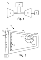
- Fig. 1 shows a schematic view of a gas turbine engine 10.
- the gas turbine engine 10 may include a compressor 12 to compress an incoming flow of air.
- the compressor 12 delivers the compressed flow of air to a combustor 14.
- the combustor 14 mixes the compressed flow of air with a compressed flow of fuel and ignites the mixture.
- the gas turbine engine 10 may include any number of combustors 14.
- the hot combustion gases are in turn delivered to a turbine 16.
- the hot combustion gases drive the turbine 16 so as to produce mechanical work.
- the mechanical work produced in the turbine 16 drives the compressor 12 and an external load 18 such as an electrical generator and the like.
- the gas turbine engine 10 may use natural gas, various types of syngas, liquid fuels, and other types of fuels.
- the gas turbine engine 10 may be an F Class engine offered by General Electric Company of Schenectady, New York or similar designs.
- the gas turbine engine 10 may have other configurations and may use other types of components.
- Other types of gas turbine engines may be used herein.
- Multiple gas turbine engines 10, other types of turbines, and other types of power generation equipment may be used herein together.
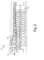
- Fig. 2 shows an example of the compressor 12.
- the compressor 12 may include a number of circumferentially spaced rotor blades 20 mounted on a rotor wheel 22. Each of the rotor wheels 22 may be attached to a driveshaft 24. The driveshaft 24 may be connected to the turbine 16.
- a number of circumferentially spaced stator blades 26 may be attached to a static compressor casing 28. The rotor blades 20 and the stator blades 26 lie in a flow path 30 beginning at a compressor inlet 32 in a staggered configuration.
- Fig. 3 shows a schematic view of a compressor 100 as may be described herein. Similar to the compressor 12 described above, the compressor 100 may include a number of rotor blades 110 attached to a rotor wheel 120 and a number of stator blades 130 attached to a compressor casing 140. The compressor 100 also defines a flow path 150 extending therethrough from a compressor inlet section 160 to a compressor aft section 170. Many other types of compressor 100 designs and components may be used herein. The compressor 100 may have any desired size. The compressor 100 described herein also may be used in other types of simple cycle or combined cycle power generation devices.
- the compressor 100 may be considered "oversized", i.e., if the operation of the overall gas turbine engine 10 declines by about ten percent (10%) to about twenty percent (20%) on a hot day, the size of the compressor 100 may be increased to provide about ten percent (10%) to about twenty percent (20%) more mass air flow rate therethrough.
- the rotor blades 110, the stator blades 130, and other components of the overall compressor 100 thus may be oversized as compared to typical compressor components.
- the compressor 100 also may have a number of inlet guide vanes 180 positioned about the compressor inlet section 160.
- the angle of the inlet guide vanes 180 may be variable. The angle may vary from a fully open position with little blockage or swirl to a fully extended or angled position of up to about five degrees (5°) to about fifteen degrees (15°). Other angles may be used herein.
- the angle of the inlet guide vanes 180 thus may vary according to the ambient conditions and the desired operating conditions as is described in more detail below. Any number or size of the inlet guide vanes 180 may be used herein.
- the compressor 100 also may have variable stator vanes used to provide flow modulation as well. For the purposes of clarity, only the inlet guide vanes 180 are shown herein.
- the compressor 100 also may include a wet compression system 190.
- the wet compression system 190 may include a number of spray heads 200 positioned about the compressor inlet section 160. Any number of spray heads 200 may be used.
- the wet compression system 190 and the spray heads 200 may be any type of water injection system.
- the wet compression system 190 injects a water droplet fog into the compressor inlet section 160 or otherwise such that the evaporation of the water reduces the compressor inlet temperature and hence the work required for compression.
- Mid-compressor injection also may be used herein. Specifically, water injection may be provided after several stages of compression.
- the inlet guide vanes 180 may be fully extended (i.e., angled) on a design condition day.
- the design condition is that predetermined ambient temperature to which the compressor 100 is designed for highest efficiency.
- the design condition day may be the ISO standard of about 59 degrees Fahrenheit (about 15 degrees Celsius) or otherwise.
- the inlet guide vanes 180 may be fully open on under hot day conditions.
- the hot day conditions may be about 110 degrees Fahrenheit (about 43.3° degrees Celsius) or otherwise above the design condition day temperatures.
- the inlet guide vanes 180 generally are fully extended on the design condition day so as to reduce the airflow to the oversized compressor 100 and fully opened on the hot day so as to provide as much airflow as is possible.
- the angle of the inlet guide vanes 180 thus may be varied with ambient temperatures and the overall operating conditions of the compressor 100.
- the compressor 100 also may use the water compression system 190 when the inlet guide vanes 180 are fully opened on a hot day and otherwise above the design condition day temperatures.
- the spray heads 200 of the wet compression system 90 inject the water droplet fog into the compressor inlet section 160, mid-section, or otherwise so as to reduce the work of compression and hence the compressor discharge temperature.
- the compressor 100 likewise may be oversized as compared to known compressors so as to overcome the reduction in power caused by a reduction in air density on a hot day.
- increased compressor discharge pressures and discharge temperatures generally may require the use of nickel based alloys for the components thereof.
- the use of the water compression system 190 on hot days thus allows for the use of lower cost "low alloy" materials for the rotor wheel 120 and perhaps other components of the compressor 100 given the minimized compressor discharge temperatures, particularly in the compressor aft section 170.
- a low alloy NiCrMoV material i.e., materials with a low alloy content, and similar types of materials with good creep resistance may be used herein.
- a balance may be found between how much power augmentation may be provided by opening the inlet guide vanes 180 for more airflow and how much via the wet compression system 190.
- modulation of the angle of the inlet guide vanes 180 may be used until the inlet guide vanes 180 are completely open.
- the wet compression system 190 likewise may be employed while the inlet guide vanes 180 are being modulated or when the vanes are open.
- the water compression system 190 serves to limit the stress and erosion issues associated with wet compression. Too much airflow without wet compression, however, may cause the compressor discharge pressure and temperature to be elevated which may promote creep.
- the angle of the inlet guide vanes 180 and the operation of the wet compression system 190 thus may be coordinated in the context of the compressor discharge pressure and temperature limits.
- a standard micro-controller 210 or an existing controller for the gas turbine engine 10 as a whole may control the operation of the inlet guide vanes 180 and the wet compression system 190 in the context of the ambient conditions so as to maximize or level the overall power generation.
- the micro-controller 210 may be of conventional design.
- the inlet guide vanes 180 may be in an extended position during the ambient design condition day but moved to an open position when the ambient conditions begin to approach hot day conditions.
- the wet compression system 190 may be used as the ambient conditions begin to approach hot day conditions or otherwise above the design condition day temperatures.
- the compressor 100 herein thus maintains level power generation even on hot days when power prices are at their maximum through the use of an oversized compressor 100, the inlet guide vanes 180, and the wet compression system 190.
- the use of the wet compression system 190 also may improve the simple cycle heat rate while not impairing the combined cycle heat rate.
- the compressor 100 also avoids the need for the use of high cost nickel alloys.
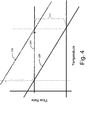
- Fig. 4 show the operation of the compressor 100 as is described herein in the context of flow rate, temperature, and power output.
- First output line 220 shows the operation of a known compressor 12. As the temperature increases, the power output declines as the flow rate declines. As is shown in second output line 230, increasing the size of the compressor 100 increases the power. Such increased power output, however, may result in increased compressor temperatures and pressures such that the more expensive alloy components may be required.
- the controller 210 herein balances the power output with the operation of the inlet guide vanes 180 and the wet compression system 190 so as to provide the level output line 240. Specifically, the inlet guide vanes 180 are closed on a design condition day to maintain the desired flow rate. The inlet guide vanes 180 are then modulated open as the temperature increases. The controller 210 likewise operates the wet compression system 190 as the temperature increases to maintain the level output line 240. Other types of power output targets may be accomplished herein with the compressor 100 and the like.
- the controller 210 also may balance the suppression of the compressor discharge temperature and the resultant power output increase with the potential for blade erosion and other potential types of damages. More specifically, the controller may balance the output benefits and the potential damage drawbacks in the context of the current price of power. In other words, the price of the power output may justify taking more of a damage risk so as to maintain the stability of the grid. Other parameters may be evaluated herein.
Landscapes
- Engineering & Computer Science (AREA)
- Mechanical Engineering (AREA)
- General Engineering & Computer Science (AREA)
- Chemical & Material Sciences (AREA)
- Combustion & Propulsion (AREA)
- Physics & Mathematics (AREA)
- Geometry (AREA)
- Structures Of Non-Positive Displacement Pumps (AREA)
Abstract
Description
- The present application relates generally to gas turbine engines and more particularly relates to gas turbine compressors and methods of operating the same over varying temperatures so as to provide a level power output.
- The mass flow rate of air through the compressor of a gas turbine engine generally varies as a function of the ambient temperature. On hot days, the density of the air may decrease by about ten percent (10%) to about twenty percent (20%) as compared to a standard ISO day ("International Organization for Standardization") of about 59 degrees Fahrenheit (about 15 degrees Celsius). As such, the overall power produced by the gas turbine engine also may be reduced by about ten percent (10%) to about twenty percent (20%) or so. This reduction in output, however, generally coincides with higher consumer and industrial power demands due to increased air conditioning loads and the like. As a result, the combination of elevated power demands and reduced generation capacity may elevate power prices by a multiple of ten or more as compared to normal power demands and capacity during a lower temperature day.
- Attempts to increase power generation on hot days have included increasing the size of the compressor to compensate for the lost flow rate. The increased scale, however, also may result in increased costs. Moreover, increased temperatures on warmer days may lead to increased compressor pressures and temperatures. Such increased pressures and temperatures generally require the use of expensive nickel based alloys at least in the aft section of the compressor so as to provide durability against low cycle fatigue. These alloys, however, may be relatively expensive as compared to standard gas turbine components.
- Various types of water cooling methods also have been used. For example, inlet fogging about the compressor inlet may reduce the compressor inlet air temperature. Such a reduction in air temperature generally restores the mass flow rate and thus the generated power. Inlet fogging, however, generally is only useful until the wet bulb temperature is reached such that the practice has limited utility on humid days. Wet compression involving a spray of water inside the compressor inlet also has been used. Latent heat for the evaporation of the water cools the inlet air stream so as to increase the power available due to the reduction of work required for compression of the inlet air. The addition of the water stream, however, may have thermal stress and/or erosion issues.
- There is thus a desire for an improved compressor and methods of operating the same so as to provide a constant level of power generation across the ambient temperature operating range, particularly on hot days. Such constant power generation would allow power producers to meet power generation requirements during periods of both high demand and hence high profitability. The compressor and methods thus should be temperature flexible while maintaining high levels of efficiency and durability.
- The present application thus provides a compressor for a gas turbine. The compressor may include a number of rotor wheels positioned about a compressor aft section having a low alloy material, a number of inlet guide vanes positioned about a compressor inlet section, and a wet compression system positioned about the compressor inlet section.
- The present application further provides for a method of operating a compressor in varying ambient temperatures so as to maintain a level power output. The method may include the steps of positioning a number of inlet guide vanes in an extended position until a predetermined ambient design condition temperature is reached, modulating the inlet guide vanes to an open position when the ambient temperature exceeds the predetermined ambient design condition temperature, and operating a wet compression system when the ambient temperature exceeds the predetermined ambient design condition temperature.
- The present application further provides for a compressor for a gas turbine. The compressor may include a number of rotor wheels with a number of oversized rotor blades positioned about a compressor aft section, a number of inlet guide vanes positioned about a compressor inlet section, and a wet compression system positioned about the compressor inlet section.
- There follows a detailed description of embodiments of the invention by way of example only with reference to the accompanying drawings, in which:
-
Fig. 1 is a schematic view of a gas turbine engine. -
Fig. 2 is a perspective exemplary view of a compressor flow path through a compressor. -
Fig. 3 is a schematic view of a compressor as is described herein. -
Fig. 4 is a chart showing a level power output as may be provided with the compressor described herein. - Referring now to the drawings, in which like numerals refer to like elements throughout the several views,
Fig. 1 shows a schematic view of agas turbine engine 10. As is known, thegas turbine engine 10 may include acompressor 12 to compress an incoming flow of air. Thecompressor 12 delivers the compressed flow of air to acombustor 14. Thecombustor 14 mixes the compressed flow of air with a compressed flow of fuel and ignites the mixture. Although only asingle combustor 14 is shown, thegas turbine engine 10 may include any number ofcombustors 14. The hot combustion gases are in turn delivered to aturbine 16. The hot combustion gases drive theturbine 16 so as to produce mechanical work. The mechanical work produced in theturbine 16 drives thecompressor 12 and anexternal load 18 such as an electrical generator and the like. - The
gas turbine engine 10 may use natural gas, various types of syngas, liquid fuels, and other types of fuels. Thegas turbine engine 10 may be an F Class engine offered by General Electric Company of Schenectady, New York or similar designs. Thegas turbine engine 10 may have other configurations and may use other types of components. Other types of gas turbine engines may be used herein. Multiplegas turbine engines 10, other types of turbines, and other types of power generation equipment may be used herein together. -
Fig. 2 shows an example of thecompressor 12. Thecompressor 12 may include a number of circumferentially spacedrotor blades 20 mounted on a rotor wheel 22. Each of the rotor wheels 22 may be attached to adriveshaft 24. Thedriveshaft 24 may be connected to theturbine 16. A number of circumferentially spacedstator blades 26 may be attached to astatic compressor casing 28. Therotor blades 20 and thestator blades 26 lie in aflow path 30 beginning at acompressor inlet 32 in a staggered configuration. -
Fig. 3 shows a schematic view of acompressor 100 as may be described herein. Similar to thecompressor 12 described above, thecompressor 100 may include a number ofrotor blades 110 attached to arotor wheel 120 and a number ofstator blades 130 attached to acompressor casing 140. Thecompressor 100 also defines aflow path 150 extending therethrough from acompressor inlet section 160 to acompressor aft section 170. Many other types ofcompressor 100 designs and components may be used herein. Thecompressor 100 may have any desired size. Thecompressor 100 described herein also may be used in other types of simple cycle or combined cycle power generation devices. - The
compressor 100 may be considered "oversized", i.e., if the operation of the overallgas turbine engine 10 declines by about ten percent (10%) to about twenty percent (20%) on a hot day, the size of thecompressor 100 may be increased to provide about ten percent (10%) to about twenty percent (20%) more mass air flow rate therethrough. Therotor blades 110, thestator blades 130, and other components of theoverall compressor 100 thus may be oversized as compared to typical compressor components. - The
compressor 100 also may have a number of inlet guide vanes 180 positioned about thecompressor inlet section 160. The angle of the inlet guide vanes 180 may be variable. The angle may vary from a fully open position with little blockage or swirl to a fully extended or angled position of up to about five degrees (5°) to about fifteen degrees (15°). Other angles may be used herein. The angle of theinlet guide vanes 180 thus may vary according to the ambient conditions and the desired operating conditions as is described in more detail below. Any number or size of theinlet guide vanes 180 may be used herein. We note that thecompressor 100 also may have variable stator vanes used to provide flow modulation as well. For the purposes of clarity, only theinlet guide vanes 180 are shown herein. - The
compressor 100 also may include awet compression system 190. Thewet compression system 190 may include a number of spray heads 200 positioned about thecompressor inlet section 160. Any number of spray heads 200 may be used. Thewet compression system 190 and the spray heads 200 may be any type of water injection system. Thewet compression system 190 injects a water droplet fog into thecompressor inlet section 160 or otherwise such that the evaporation of the water reduces the compressor inlet temperature and hence the work required for compression. Mid-compressor injection also may be used herein. Specifically, water injection may be provided after several stages of compression. - In use, the
inlet guide vanes 180 may be fully extended (i.e., angled) on a design condition day. The design condition is that predetermined ambient temperature to which thecompressor 100 is designed for highest efficiency. The design condition day may be the ISO standard of about 59 degrees Fahrenheit (about 15 degrees Celsius) or otherwise. Theinlet guide vanes 180 may be fully open on under hot day conditions. The hot day conditions may be about 110 degrees Fahrenheit (about 43.3° degrees Celsius) or otherwise above the design condition day temperatures. Theinlet guide vanes 180 generally are fully extended on the design condition day so as to reduce the airflow to theoversized compressor 100 and fully opened on the hot day so as to provide as much airflow as is possible. The angle of theinlet guide vanes 180 thus may be varied with ambient temperatures and the overall operating conditions of thecompressor 100. - The
compressor 100 also may use thewater compression system 190 when theinlet guide vanes 180 are fully opened on a hot day and otherwise above the design condition day temperatures. The spray heads 200 of the wet compression system 90 inject the water droplet fog into thecompressor inlet section 160, mid-section, or otherwise so as to reduce the work of compression and hence the compressor discharge temperature. - The
compressor 100 likewise may be oversized as compared to known compressors so as to overcome the reduction in power caused by a reduction in air density on a hot day. As described above, increased compressor discharge pressures and discharge temperatures generally may require the use of nickel based alloys for the components thereof. The use of thewater compression system 190 on hot days thus allows for the use of lower cost "low alloy" materials for therotor wheel 120 and perhaps other components of thecompressor 100 given the minimized compressor discharge temperatures, particularly in thecompressor aft section 170. For example, a low alloy NiCrMoV material, i.e., materials with a low alloy content, and similar types of materials with good creep resistance may be used herein. - A balance may be found between how much power augmentation may be provided by opening the
inlet guide vanes 180 for more airflow and how much via thewet compression system 190. Generally, modulation of the angle of theinlet guide vanes 180 may be used until theinlet guide vanes 180 are completely open. Thewet compression system 190 likewise may be employed while theinlet guide vanes 180 are being modulated or when the vanes are open. Thewater compression system 190 serves to limit the stress and erosion issues associated with wet compression. Too much airflow without wet compression, however, may cause the compressor discharge pressure and temperature to be elevated which may promote creep. The angle of theinlet guide vanes 180 and the operation of thewet compression system 190 thus may be coordinated in the context of the compressor discharge pressure and temperature limits. - A
standard micro-controller 210 or an existing controller for thegas turbine engine 10 as a whole may control the operation of theinlet guide vanes 180 and thewet compression system 190 in the context of the ambient conditions so as to maximize or level the overall power generation. Themicro-controller 210 may be of conventional design. For example, theinlet guide vanes 180 may be in an extended position during the ambient design condition day but moved to an open position when the ambient conditions begin to approach hot day conditions. Likewise, thewet compression system 190 may be used as the ambient conditions begin to approach hot day conditions or otherwise above the design condition day temperatures. - The
compressor 100 herein thus maintains level power generation even on hot days when power prices are at their maximum through the use of anoversized compressor 100, theinlet guide vanes 180, and thewet compression system 190. The use of thewet compression system 190 also may improve the simple cycle heat rate while not impairing the combined cycle heat rate. Thecompressor 100 also avoids the need for the use of high cost nickel alloys. -
Fig. 4 show the operation of thecompressor 100 as is described herein in the context of flow rate, temperature, and power output.First output line 220 shows the operation of a knowncompressor 12. As the temperature increases, the power output declines as the flow rate declines. As is shown insecond output line 230, increasing the size of thecompressor 100 increases the power. Such increased power output, however, may result in increased compressor temperatures and pressures such that the more expensive alloy components may be required. - The
controller 210 herein balances the power output with the operation of theinlet guide vanes 180 and thewet compression system 190 so as to provide thelevel output line 240. Specifically, theinlet guide vanes 180 are closed on a design condition day to maintain the desired flow rate. Theinlet guide vanes 180 are then modulated open as the temperature increases. Thecontroller 210 likewise operates thewet compression system 190 as the temperature increases to maintain thelevel output line 240. Other types of power output targets may be accomplished herein with thecompressor 100 and the like. - Moreover, the
controller 210 also may balance the suppression of the compressor discharge temperature and the resultant power output increase with the potential for blade erosion and other potential types of damages. More specifically, the controller may balance the output benefits and the potential damage drawbacks in the context of the current price of power. In other words, the price of the power output may justify taking more of a damage risk so as to maintain the stability of the grid. Other parameters may be evaluated herein. - It should be apparent that the foregoing relates only to certain embodiments of the present application and that numerous changes and modifications may be made herein by one of ordinary skill in the art without departing from the general spirit and scope of the invention as defined by the following claims and the equivalents thereof.
- For completeness, various aspects of the invention are now set out in the following numbered clauses:
- 1. A compressor for a gas turbine, comprising:
- a plurality of rotor wheels positioned about a compressor aft section;
- the plurality of rotor wheels comprising a low alloy material;
- a plurality of inlet guide vanes positioned about a compressor inlet section; and
- a wet compression system positioned about the compressor inlet section.
- 2. The compressor of clause 1, further comprising a plurality of rotor blades attached to the rotor wheel and wherein the plurality of rotor blades is oversized.
- 3. The compressor of clause 1, wherein the plurality of inlet guide vanes are capable of an open position and a fully extended position.
- 4. The compressor of clause 1, wherein the wet compression system comprises a plurality of spray heads.
- 5. The compressor of clause 1, further comprising a controller in communication with the plurality of inlet guide vanes and the wet compression system.
- 6. The compressor of clause 1, wherein the low alloy material comprises a NiCrMoV material.
- 7. The compressor of clause 1, wherein the low alloy material comprises a creep resistant material.
- 8. A method of operating a compressor in varying ambient temperatures so as to maintain a level power output, comprising:
- positioning a plurality of inlet guide vanes in an extended position until a predetermined ambient design condition temperature is reached;
- modulating the plurality of inlet guide vanes to an open position when the ambient temperature exceeds the predetermined ambient design condition temperature; and
- operating a wet compression system when the ambient temperature exceeds the predetermined ambient design condition temperature.
- 9. The method of clause 8, wherein operating a wet compression system comprises spraying water from a plurality of spray heads.
- 10. The method of clause 8, further comprising oversizing the compressor.
- 11. The method of clause 8, wherein the step of operating a wet compression system follows the step of positioning the plurality of inlet guide vanes in an open position.
- 12. The method of clause 8, further comprising monitoring a compressor discharge pressure and temperature.
- 13. The method of clause 8, wherein the modulating and the operating steps are controlled in the context of a current cost of the level power output.
- 14. A compressor for a gas turbine, comprising:
- a plurality of rotor wheels positioned about a compressor aft section;
- the plurality of rotor wheels comprising a plurality of oversized rotor blades;
- a plurality of inlet guide vanes positioned about a compressor inlet section; and
- a wet compression system positioned about the compressor inlet section.
- 15. The compressor of
clause 14, wherein the plurality of inlet guide vanes comprises an open position and a fully extended position. - 16. The compressor of
clause 14, wherein the wet compression system comprises a plurality of spray heads. - 17. The compressor of
clause 14, further comprising a controller in communication with the plurality of inlet guide vanes and the wet compression system. - 18. The compressor of
clause 14, wherein rotor wheel comprises a low alloy material. - 19. The compressor of
clause 18, wherein the low alloy material comprises a NiCrMoV material. - 20. The compressor of
clause 18, wherein the low alloy material comprises a creep resistant material.
Claims (13)
- A compressor (100) for a gas turbine (10), comprising:a plurality of rotor wheels (120) positioned about a compressor aft section (170);the plurality of rotor wheels (120) comprising a low alloy material;a plurality of inlet guide vanes (180) positioned about a compressor inlet section (160);anda wet compression system (190) positioned about the compressor inlet section (160).
- The compressor (100) of claim 1, further comprising a plurality of rotor blades (110) attached to the rotor wheel (120) and wherein the plurality of rotor blades (110) is oversized.
- The compressor (100) of claim 1 or 2, wherein the plurality of inlet guide vanes (180) are capable of an open position and a fully extended position.
- The compressor (100) of any of the preceding claims, wherein the wet compression system (190) comprises a plurality of spray heads (200).
- The compressor (100) of any of the preceding claims, further comprising a controller (210) in communication with the plurality of inlet guide vanes (180) and the wet compression system (190).
- The compressor (100) of any of the preceding claims, wherein the low alloy material comprises a NiCrMoV material.
- The compressor (100) of any of the preceding claims, wherein the low alloy material comprises a creep resistant material.
- A method of operating a compressor (100) in varying ambient temperatures so as to maintain a level power output (240), comprising:positioning a plurality of inlet guide vanes (180) in an extended position until a predetermined ambient design condition temperature is reached;modulating the plurality of inlet guide vanes (180) to an open position when the ambient temperature exceed the predetermined ambient design condition temperature;andoperating a wet compression system (190) when the ambient temperature exceeds the predetermined ambient design condition temperature.
- The method of claim 8, wherein operating a wet compression system (190) comprises spraying water from a plurality of spray heads (200).
- The method of claim 8 or 9, further comprising oversizing the compressor (100).
- The method of any of claims 8 to 10, wherein the step of operating a wet compression system (190) follows the step of positioning the plurality of inlet guide vanes (180) in an open position.
- The method of any of claims 8 to 11, further comprising monitoring a compressor discharge pressure and temperature.
- The method of any of claims 8 to 12, further comprising the step of installing a low alloy rotor wheel (120).
Applications Claiming Priority (1)
| Application Number | Priority Date | Filing Date | Title |
|---|---|---|---|
| US12/615,288 US8475117B2 (en) | 2009-11-10 | 2009-11-10 | Gas turbine compressor and method of operation |
Publications (2)
| Publication Number | Publication Date |
|---|---|
| EP2320050A2 true EP2320050A2 (en) | 2011-05-11 |
| EP2320050A3 EP2320050A3 (en) | 2018-02-07 |
Family
ID=43414831
Family Applications (1)
| Application Number | Title | Priority Date | Filing Date |
|---|---|---|---|
| EP10189803.9A Withdrawn EP2320050A3 (en) | 2009-11-10 | 2010-11-03 | Gas turbine compressor and method of operation |
Country Status (4)
| Country | Link |
|---|---|
| US (1) | US8475117B2 (en) |
| EP (1) | EP2320050A3 (en) |
| JP (1) | JP5855821B2 (en) |
| CN (1) | CN102062078B (en) |
Families Citing this family (7)
| Publication number | Priority date | Publication date | Assignee | Title |
|---|---|---|---|---|
| EP2969740B1 (en) * | 2013-03-15 | 2020-05-06 | President and Fellows of Harvard College | Void structures with repeating elongated-aperture pattern |
| JP6185781B2 (en) * | 2013-07-23 | 2017-08-23 | 三菱日立パワーシステムズ株式会社 | Axial flow compressor |
| US20150033751A1 (en) * | 2013-07-31 | 2015-02-05 | General Electric Company | System and method for a water injection system |
| US9440353B1 (en) | 2014-12-29 | 2016-09-13 | Google Inc. | Offline determination of robot behavior |
| US20170167389A1 (en) * | 2015-12-15 | 2017-06-15 | General Electric Company | System and Method for Controlling Gas Turbine Exhaust Energy Via Exhaust Gas Damper and Compressed Gas Supply |
| JP7032015B2 (en) | 2016-05-03 | 2022-03-08 | ゼネラル・エレクトリック・カンパニイ | Liquid injection device, and compressor assembly with liquid injection device |
| US10502220B2 (en) * | 2016-07-22 | 2019-12-10 | Solar Turbines Incorporated | Method for improving turbine compressor performance |
Family Cites Families (16)
| Publication number | Priority date | Publication date | Assignee | Title |
|---|---|---|---|---|
| JPS63272923A (en) * | 1987-05-01 | 1988-11-10 | Mitsui Eng & Shipbuild Co Ltd | Control method for output of gas turbine |
| JP3845875B2 (en) * | 1994-12-13 | 2006-11-15 | 株式会社日立製作所 | Gas turbine compressor and gas turbine |
| JP2877098B2 (en) * | 1995-12-28 | 1999-03-31 | 株式会社日立製作所 | Gas turbines, combined cycle plants and compressors |
| JPH1172029A (en) * | 1997-06-30 | 1999-03-16 | Hitachi Ltd | Gas turbine with power increase mechanism by water spray |
| DE19907907A1 (en) * | 1999-02-24 | 2000-08-31 | Abb Alstom Power Ch Ag | Multi-stage turbo compressor |
| US6582195B2 (en) * | 2001-06-27 | 2003-06-24 | General Electric Company | Compressor rotor blade spacer apparatus |
| GB2382847A (en) * | 2001-12-06 | 2003-06-11 | Alstom | Gas turbine wet compression |
| JP4495971B2 (en) * | 2002-01-25 | 2010-07-07 | アルストム テクノロジー リミテッド | Method for operating a gas turbine group |
| US7310950B2 (en) * | 2002-09-13 | 2007-12-25 | Siemens Power Generation, Inc. | Inlet airflow cooling control for a power generating system |
| ES2547641T3 (en) * | 2003-02-11 | 2015-10-07 | Alstom Technology Ltd | Procedure to operate a group of gas turbines |
| US6935119B2 (en) * | 2003-03-14 | 2005-08-30 | General Electric Company | Methods for operating gas turbine engines |
| DE10342097A1 (en) * | 2003-09-10 | 2005-04-07 | Alstom Technology Ltd | Axial Compressor |
| CA2606756C (en) * | 2005-05-02 | 2013-10-08 | Vast Power Portfolio, Llc | Wet compression apparatus and method |
| US7644573B2 (en) * | 2006-04-18 | 2010-01-12 | General Electric Company | Gas turbine inlet conditioning system and method |
| US7854809B2 (en) * | 2007-04-10 | 2010-12-21 | Siemens Energy, Inc. | Heat treatment system for a composite turbine engine component |
| US8137075B2 (en) * | 2007-08-31 | 2012-03-20 | Honeywell International Inc. | Compressor impellers, compressor sections including the compressor impellers, and methods of manufacturing |
-
2009
- 2009-11-10 US US12/615,288 patent/US8475117B2/en not_active Expired - Fee Related
-
2010
- 2010-11-03 EP EP10189803.9A patent/EP2320050A3/en not_active Withdrawn
- 2010-11-08 JP JP2010249248A patent/JP5855821B2/en not_active Expired - Fee Related
- 2010-11-10 CN CN201010552323.3A patent/CN102062078B/en not_active Expired - Fee Related
Non-Patent Citations (1)
| Title |
|---|
| None |
Also Published As
| Publication number | Publication date |
|---|---|
| EP2320050A3 (en) | 2018-02-07 |
| US20110110758A1 (en) | 2011-05-12 |
| JP5855821B2 (en) | 2016-02-09 |
| US8475117B2 (en) | 2013-07-02 |
| CN102062078A (en) | 2011-05-18 |
| CN102062078B (en) | 2015-12-16 |
| JP2011102584A (en) | 2011-05-26 |
Similar Documents
| Publication | Publication Date | Title |
|---|---|---|
| EP2320050A2 (en) | Gas turbine compressor and method of operation | |
| US8240975B1 (en) | Multiple staged compressor with last stage airfoil cooling | |
| KR101907295B1 (en) | Two-shaft gas turbine and method of controlling opening degree of inlet guide vane of the same | |
| CN104265461B (en) | For the method carrying air to gas turbine from compound compressor | |
| US9605556B2 (en) | Power station and method for its operation | |
| Badeer | GE aeroderivative gas turbines-design and operating features | |
| US20130298565A1 (en) | Gas turbine engine systems and related methods involving multiple gas turbine cores | |
| US20110210555A1 (en) | Gas turbine driven electric power system with constant output through a full range of ambient conditions | |
| US8152457B2 (en) | Compressor clearance control system using bearing oil waste heat | |
| US20130170962A1 (en) | Forward Step Honeycomb Seal for Turbine Shroud | |
| US10156242B2 (en) | Gas turbine and method for its operation | |
| EP2208862A2 (en) | Compressor clearance control system using turbine exhaust | |
| Bringhenti et al. | Methodology for gas turbine performance improvement using variable-geometry compressors and turbines | |
| EP2823168A1 (en) | Gas turbine engine configured to shape power output | |
| EP2613013B1 (en) | Stage and turbine of a gas turbine engine | |
| KR102042907B1 (en) | Method for manufacturing gas turbine | |
| CN106351744A (en) | Power augmentation system for a gas turbine | |
| JP2012500362A5 (en) | ||
| CN102926875B (en) | For controlling the method for the output of gas turbine and corresponding gas turbine engine systems | |
| EP3128154A1 (en) | Systems and methods for augmenting gas turbine power output with a pressurized air tank and/or an external compressor | |
| US9470098B2 (en) | Axial compressor and method for controlling stage-to-stage leakage therein | |
| US9458731B2 (en) | Turbine shroud cooling system | |
| Nasir et al. | Design and off-design operation and performance analysis of a gas turbine | |
| Rocha et al. | Introduction of the Taurus™ 65 industrial gas turbine for power generation | |
| US20240026801A1 (en) | Rotor cooling system for shutdown |
Legal Events
| Date | Code | Title | Description |
|---|---|---|---|
| PUAI | Public reference made under article 153(3) epc to a published international application that has entered the european phase |
Free format text: ORIGINAL CODE: 0009012 |
|
| AK | Designated contracting states |
Kind code of ref document: A2 Designated state(s): AL AT BE BG CH CY CZ DE DK EE ES FI FR GB GR HR HU IE IS IT LI LT LU LV MC MK MT NL NO PL PT RO RS SE SI SK SM TR |
|
| AX | Request for extension of the european patent |
Extension state: BA ME |
|
| PUAL | Search report despatched |
Free format text: ORIGINAL CODE: 0009013 |
|
| AK | Designated contracting states |
Kind code of ref document: A3 Designated state(s): AL AT BE BG CH CY CZ DE DK EE ES FI FR GB GR HR HU IE IS IT LI LT LU LV MC MK MT NL NO PL PT RO RS SE SI SK SM TR |
|
| AX | Request for extension of the european patent |
Extension state: BA ME |
|
| RIC1 | Information provided on ipc code assigned before grant |
Ipc: F02C 7/143 20060101AFI20180102BHEP Ipc: F04D 29/70 20060101ALI20180102BHEP |
|
| STAA | Information on the status of an ep patent application or granted ep patent |
Free format text: STATUS: THE APPLICATION IS DEEMED TO BE WITHDRAWN |
|
| 18D | Application deemed to be withdrawn |
Effective date: 20180602 |