EP2320035A1 - Variable valve device for internal combustion engine - Google Patents
Variable valve device for internal combustion engine Download PDFInfo
- Publication number
- EP2320035A1 EP2320035A1 EP10190188A EP10190188A EP2320035A1 EP 2320035 A1 EP2320035 A1 EP 2320035A1 EP 10190188 A EP10190188 A EP 10190188A EP 10190188 A EP10190188 A EP 10190188A EP 2320035 A1 EP2320035 A1 EP 2320035A1
- Authority
- EP
- European Patent Office
- Prior art keywords
- phase variable
- cam phase
- engine
- cam
- intake
- Prior art date
- Legal status (The legal status is an assumption and is not a legal conclusion. Google has not performed a legal analysis and makes no representation as to the accuracy of the status listed.)
- Granted
Links
Images


Classifications
-
- F—MECHANICAL ENGINEERING; LIGHTING; HEATING; WEAPONS; BLASTING
- F01—MACHINES OR ENGINES IN GENERAL; ENGINE PLANTS IN GENERAL; STEAM ENGINES
- F01L—CYCLICALLY OPERATING VALVES FOR MACHINES OR ENGINES
- F01L1/00—Valve-gear or valve arrangements, e.g. lift-valve gear
- F01L1/34—Valve-gear or valve arrangements, e.g. lift-valve gear characterised by the provision of means for changing the timing of the valves without changing the duration of opening and without affecting the magnitude of the valve lift
-
- F—MECHANICAL ENGINEERING; LIGHTING; HEATING; WEAPONS; BLASTING
- F01—MACHINES OR ENGINES IN GENERAL; ENGINE PLANTS IN GENERAL; STEAM ENGINES
- F01L—CYCLICALLY OPERATING VALVES FOR MACHINES OR ENGINES
- F01L1/00—Valve-gear or valve arrangements, e.g. lift-valve gear
- F01L1/02—Valve drive
- F01L1/04—Valve drive by means of cams, camshafts, cam discs, eccentrics or the like
- F01L1/047—Camshafts
-
- F—MECHANICAL ENGINEERING; LIGHTING; HEATING; WEAPONS; BLASTING
- F01—MACHINES OR ENGINES IN GENERAL; ENGINE PLANTS IN GENERAL; STEAM ENGINES
- F01L—CYCLICALLY OPERATING VALVES FOR MACHINES OR ENGINES
- F01L1/00—Valve-gear or valve arrangements, e.g. lift-valve gear
- F01L1/34—Valve-gear or valve arrangements, e.g. lift-valve gear characterised by the provision of means for changing the timing of the valves without changing the duration of opening and without affecting the magnitude of the valve lift
- F01L1/344—Valve-gear or valve arrangements, e.g. lift-valve gear characterised by the provision of means for changing the timing of the valves without changing the duration of opening and without affecting the magnitude of the valve lift changing the angular relationship between crankshaft and camshaft, e.g. using helicoidal gear
-
- F—MECHANICAL ENGINEERING; LIGHTING; HEATING; WEAPONS; BLASTING
- F02—COMBUSTION ENGINES; HOT-GAS OR COMBUSTION-PRODUCT ENGINE PLANTS
- F02D—CONTROLLING COMBUSTION ENGINES
- F02D13/00—Controlling the engine output power by varying inlet or exhaust valve operating characteristics, e.g. timing
- F02D13/02—Controlling the engine output power by varying inlet or exhaust valve operating characteristics, e.g. timing during engine operation
- F02D13/0223—Variable control of the intake valves only
- F02D13/0234—Variable control of the intake valves only changing the valve timing only
- F02D13/0238—Variable control of the intake valves only changing the valve timing only by shifting the phase, i.e. the opening periods of the valves are constant
-
- F—MECHANICAL ENGINEERING; LIGHTING; HEATING; WEAPONS; BLASTING
- F02—COMBUSTION ENGINES; HOT-GAS OR COMBUSTION-PRODUCT ENGINE PLANTS
- F02D—CONTROLLING COMBUSTION ENGINES
- F02D13/00—Controlling the engine output power by varying inlet or exhaust valve operating characteristics, e.g. timing
- F02D13/02—Controlling the engine output power by varying inlet or exhaust valve operating characteristics, e.g. timing during engine operation
- F02D13/0257—Independent control of two or more intake or exhaust valves respectively, i.e. one of two intake valves remains closed or is opened partially while the other is fully opened
-
- F—MECHANICAL ENGINEERING; LIGHTING; HEATING; WEAPONS; BLASTING
- F02—COMBUSTION ENGINES; HOT-GAS OR COMBUSTION-PRODUCT ENGINE PLANTS
- F02D—CONTROLLING COMBUSTION ENGINES
- F02D41/00—Electrical control of supply of combustible mixture or its constituents
- F02D41/0002—Controlling intake air
-
- F—MECHANICAL ENGINEERING; LIGHTING; HEATING; WEAPONS; BLASTING
- F01—MACHINES OR ENGINES IN GENERAL; ENGINE PLANTS IN GENERAL; STEAM ENGINES
- F01L—CYCLICALLY OPERATING VALVES FOR MACHINES OR ENGINES
- F01L1/00—Valve-gear or valve arrangements, e.g. lift-valve gear
- F01L1/02—Valve drive
- F01L1/04—Valve drive by means of cams, camshafts, cam discs, eccentrics or the like
- F01L1/047—Camshafts
- F01L2001/0471—Assembled camshafts
- F01L2001/0473—Composite camshafts, e.g. with cams or cam sleeve being able to move relative to the inner camshaft or a cam adjusting rod
-
- F—MECHANICAL ENGINEERING; LIGHTING; HEATING; WEAPONS; BLASTING
- F01—MACHINES OR ENGINES IN GENERAL; ENGINE PLANTS IN GENERAL; STEAM ENGINES
- F01L—CYCLICALLY OPERATING VALVES FOR MACHINES OR ENGINES
- F01L1/00—Valve-gear or valve arrangements, e.g. lift-valve gear
- F01L1/34—Valve-gear or valve arrangements, e.g. lift-valve gear characterised by the provision of means for changing the timing of the valves without changing the duration of opening and without affecting the magnitude of the valve lift
- F01L1/344—Valve-gear or valve arrangements, e.g. lift-valve gear characterised by the provision of means for changing the timing of the valves without changing the duration of opening and without affecting the magnitude of the valve lift changing the angular relationship between crankshaft and camshaft, e.g. using helicoidal gear
- F01L2001/34486—Location and number of the means for changing the angular relationship
- F01L2001/34489—Two phasers on one camshaft
-
- F—MECHANICAL ENGINEERING; LIGHTING; HEATING; WEAPONS; BLASTING
- F01—MACHINES OR ENGINES IN GENERAL; ENGINE PLANTS IN GENERAL; STEAM ENGINES
- F01L—CYCLICALLY OPERATING VALVES FOR MACHINES OR ENGINES
- F01L1/00—Valve-gear or valve arrangements, e.g. lift-valve gear
- F01L1/34—Valve-gear or valve arrangements, e.g. lift-valve gear characterised by the provision of means for changing the timing of the valves without changing the duration of opening and without affecting the magnitude of the valve lift
- F01L1/344—Valve-gear or valve arrangements, e.g. lift-valve gear characterised by the provision of means for changing the timing of the valves without changing the duration of opening and without affecting the magnitude of the valve lift changing the angular relationship between crankshaft and camshaft, e.g. using helicoidal gear
- F01L2001/34486—Location and number of the means for changing the angular relationship
- F01L2001/34493—Dual independent phasing system [DIPS]
-
- F—MECHANICAL ENGINEERING; LIGHTING; HEATING; WEAPONS; BLASTING
- F01—MACHINES OR ENGINES IN GENERAL; ENGINE PLANTS IN GENERAL; STEAM ENGINES
- F01L—CYCLICALLY OPERATING VALVES FOR MACHINES OR ENGINES
- F01L2800/00—Methods of operation using a variable valve timing mechanism
-
- F—MECHANICAL ENGINEERING; LIGHTING; HEATING; WEAPONS; BLASTING
- F02—COMBUSTION ENGINES; HOT-GAS OR COMBUSTION-PRODUCT ENGINE PLANTS
- F02D—CONTROLLING COMBUSTION ENGINES
- F02D41/00—Electrical control of supply of combustible mixture or its constituents
- F02D41/0002—Controlling intake air
- F02D2041/001—Controlling intake air for engines with variable valve actuation
-
- Y—GENERAL TAGGING OF NEW TECHNOLOGICAL DEVELOPMENTS; GENERAL TAGGING OF CROSS-SECTIONAL TECHNOLOGIES SPANNING OVER SEVERAL SECTIONS OF THE IPC; TECHNICAL SUBJECTS COVERED BY FORMER USPC CROSS-REFERENCE ART COLLECTIONS [XRACs] AND DIGESTS
- Y02—TECHNOLOGIES OR APPLICATIONS FOR MITIGATION OR ADAPTATION AGAINST CLIMATE CHANGE
- Y02T—CLIMATE CHANGE MITIGATION TECHNOLOGIES RELATED TO TRANSPORTATION
- Y02T10/00—Road transport of goods or passengers
- Y02T10/10—Internal combustion engine [ICE] based vehicles
- Y02T10/12—Improving ICE efficiencies
-
- Y—GENERAL TAGGING OF NEW TECHNOLOGICAL DEVELOPMENTS; GENERAL TAGGING OF CROSS-SECTIONAL TECHNOLOGIES SPANNING OVER SEVERAL SECTIONS OF THE IPC; TECHNICAL SUBJECTS COVERED BY FORMER USPC CROSS-REFERENCE ART COLLECTIONS [XRACs] AND DIGESTS
- Y02—TECHNOLOGIES OR APPLICATIONS FOR MITIGATION OR ADAPTATION AGAINST CLIMATE CHANGE
- Y02T—CLIMATE CHANGE MITIGATION TECHNOLOGIES RELATED TO TRANSPORTATION
- Y02T10/00—Road transport of goods or passengers
- Y02T10/10—Internal combustion engine [ICE] based vehicles
- Y02T10/40—Engine management systems
Definitions
- the present invention relates to a variable valve device for internal combustion engines, and more particularly, to techniques for optimizing valve opening/closing timings of intake and exhaust valves.
- cam phase variable mechanisms as a variable valve device for varying valve opening/closing timings (cam phases).
- cam phase variable mechanisms are applied to an engine having each cylinder provided with a plurality of intake valves and the valve opening/closing timings of all intake valves as well as only some of the intake valves are varied (split) in accordance with the operating condition of the engine (Japanese Laid-open Patent Publication No. 2009-144521 ).
- valve opening/closing timings of only some of the intake valves associated with the individual cylinders can be varied in this manner, the multiple intake valves can be made to open continuously as a whole, whereby highly flexible valve control can be executed so that the overall valve open period of the intake valves may be prolonged, making it possible to improve the operational performance of the engine.
- actuators for such cam phase variable mechanisms hydraulic actuators operated by means of operating oil pressure are generally used.
- a vane-type hydraulic actuator is used for an actuator for actuating all of the intake valves as well as for an actuator for actuating only some of the intake valves.
- An object of the present invention is to provide a variable valve device for an internal combustion engine which is capable of precisely controlling cam phases, thereby improving operational performance of the engine.
- the present invention provides a variable valve device for an internal combustion engine including cylinders each provided with a first intake valve actuated by is first intake cam and a second intake valve actuated by a second intake cam, the variable valve device including a first cam phase variable mechanism capable of varying phases of both the first and second intake cams, and a second cam phase variable mechanism capable of varying the phase of the second intake cam relative to that of the first intake cam, characterized in that the variable valve device further comprises phase variable control unit that controls the first and second cam phase variable mechanisms, and the phase variable control unit preferentially controls one of the first and second cam phase variable mechanisms over the other in accordance with an operating condition of the engine.
- variable valve device for an internal combustion engine is provided with the first cam phase variable mechanism capable of varying the phases of both the first and second intake cams by using operating oil pressure, and also with the second cam phase variable mechanism having a split change function and capable of retarding the phase of the second intake cam relative to that of the first intake cam by using the operating oil pressure, and one of the first and second cam phase variable mechanisms is preferentially controlled over the other in accordance with the operating condition of the engine.
- the first or second cam phase variable mechanism can be stably controlled in accordance with the operating condition of the engine, so that the phase of the first or second intake cam can be controlled with high precision to improve the output of the engine and also reduce the fuel cost, making it possible to improve the operational performance of the engine.
- the phase variable control unit preferentially controls one of the first and second cam phase variable mechanisms over the other in accordance with a region in which the engine is operating and which is determined by at least one of rotating speed and load of the engine.
- the first or second cam phase variable mechanism can be stably controlled in accordance with the rotating speed and load of the engine, so that the phase of the first or second intake cam can be precisely controlled to improve the engine output and also reduce the fuel cost, thereby making it possible to improve the operational performance of the engine.
- the phase variable control unit preferentially controls the second cam phase variable mechanism when the engine is operating in a low-speed, low-load region in which the rotating speed is lower than a predetermined rotating speed and also the load is lower than a predetermined load.
- the first cam phase variable mechanism is not controlled with the supply of the operating oil pressure stopped, and the operating oil pressure is supplied only to the second cam phase variable mechanism.
- phase of the second intake cam can therefore be precisely controlled to improve the output of the engine and also reduce the fuel cost, whereby the operational performance of the engine can be improved.
- the engine includes a throttle valve arranged in an intake passage thereof and capable of adjusting the amount of intake air, and the phase variable control unit preferentially controls the first cam phase variable mechanism when the engine is operating in a high-load region in which the load is higher than or equal to the predetermined load.
- the second cam phase variable mechanism is not controlled with the supply of the operating oil pressure stopped, and the operating oil pressure is supplied only to the first cam phase variable mechanism.
- phase of the first intake cam can therefore be precisely controlled to improve the output of the engine and also reduce the fuel cost, so that the operational performance of the engine can be improved.
- the phase variable control unit stops preferentially controlling one of the first and second cam phase variable mechanisms over the other when the engine is operating in a high-speed region in which the rotating speed is higher than or equal to the predetermined rotating speed.
- the first cam phase variable mechanism is fixed at the most retarded position and the second cam phase variable mechanism is fixed at the most advanced position.
- phase of the first intake cam can therefore be precisely controlled to improve the engine output and also reduce the fuel cost, whereby the operational performance of the engine can be improved.
- the phase variable control unit includes target value setting unit that sets a control target value for each of the first and second cam phase variable mechanisms, and dead zone setting unit that sets a dead zone with respect to each of the control target values set by the target value setting unit, wherein the dead zone setting unit sets the dead zones such that the dead zone associated with one of the first and second cam phase variable mechanisms which is to be preferentially controlled is narrower than the dead zone associated with the other of the first and second cam phase variable mechanisms.
- the first or second cam phase variable mechanism can be stably controlled, so that the phase of the first or second intake cam can be precisely controlled to improve the engine output and also reduce the fuel cost, making it possible to improve the operational performance of the engine.
- the phase variable control unit advances control start timing of one of the first and second cam phase variable mechanisms which is to be preferentially controlled over the other.
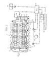
- FIG. 1 schematically illustrates the construction of a variable valve device for an internal combustion engine according to the present invention. More particularly, FIG. 1 is a top view showing the internal structure of a cylinder head 2 of an engine 1.
- the engine 1 is an in-line four-cylinder engine with a DOHC valve train, for example.
- cam sprockets 5 and 6 are connected to exhaust and intake camshafts 3 and 4, respectively, rotatably supported inside the cylinder head 2, and are also coupled to a crankshaft, not shown, by a chain 7.
- Each cylinder 8 of the engine 1 is provided with two intake valves 9 and 10 and two exhaust valves, not shown.
- the two intake valves 9 and 10 are actuated by first and second intake cams 11 and 12, respectively, which are alternately arranged on the intake camshaft 4. Specifically, out of the two intake valves, the first intake valve 9 is actuated by the first intake cam 11, and the second intake valve 10 by the second intake cam 12.
- the two exhaust valves are actuated by respective exhaust cams 13 fixed on the exhaust camshaft 3.
- the intake camshaft 4 has a double structure comprising a hollow outer camshaft and an inner camshaft inserted through the outer camshaft.
- the outer and inner camshafts are coaxially arranged with some gap therebetween and are rotatably supported by a plurality of cam journals 23 formed on the cylinder head 2 of the engine 1.
- the first intake cams 11 are fixed on the outer camshaft, while the second intake cams 12 are rotatably supported on the outer camshaft.
- the second intake cams 12 are fixed to the inner camshaft by fixing pins fitted through circumferentially elongated holes formed through the outer camshaft. Consequently, the first intake cams 11 are driven by rotation of the outer camshaft, while the second intake cams 12 are driven by rotation of the inner camshaft.
- the intake camshaft 4 is provided with a first cam phase variable mechanism 30 and a second cam phase variable mechanism 31.
- a vane-type hydraulic actuator conventionally known in the art is used, for example.
- the vane-type hydraulic actuator includes a cylindrical housing (cover) and a vane rotor rotatably arranged in the housing, and has the function of varying the rotational angle of the vane relative to the housing in accordance with the amount of operating oil supplied to the interior of the housing from a hydraulic unit 50 via a solenoid-operated hydraulic valve 52, 54, tamely, in accordance with the operating oil pressure.
- the first cam phase variable mechanism 30 is attached to the front end of the intake camshaft 4 with the housing fixed to the cam sprocket 6 and with the vane rotor fixed to the outer camshaft.
- the second cam phase variable mechanism 31 is attached to the rear end of the intake camshaft 4, and the outer and inner camshafts are fixed, respectively, to the housing and the vane rotor of the second cam phase variable mechanism 31.
- the first cam phase variable mechanism 30 provides the function of varying the rotational angle of the outer camshaft relative to the cam sprocket 6, while the second cam phase variable mechanism 31 provides the function of varying the rotational angle of the inner camshaft relative to the outer camshaft.
- the first cam phase variable mechanism 30 has the function of varying the valve opening/closing timing of the first and second intake valves 9 and 10 as a whole with respect to the valve opening/closing timing of the exhaust valves
- the second cam phase variable mechanism 31 has a split change function, namely, the function of varying a phase difference (amount of split) between the valve opening/closing timings of the first and second intake valves 9 and 10.
- a first cam sensor 32 for detecting an actual rotational angle of the outer camshaft is mounted to the cylinder head 2.
- the opening of the hydraulic valve 52 is adjusted so as to control the operation of the first cam phase variable mechanism 30.
- the second cam phase variable mechanism 31 is covered with an actuator cover 40.
- a second cam sensor 45 which detects the rotation timing of the vane rotor of the second cam phase variable mechanism 31 to detect an actual rotational angle of the inner camshaft.
- an actual rotational angle difference between the inner and outer camshafts can be detected from the information provided by the first and second cam sensors 32 and 45, and the opening of the solenoid-operated hydraulic valve 54 is adjusted on the basis of the actual rotational angle difference, whereby the operation of the second cam phase variable mechanism 31 can be controlled.
- An electronic control unit (ECU) 60 is a controller for performing various control operations on the engine 1 and comprises a CPU, memories, and so forth.
- Various sensors including an accelerator position sensor (APS) 62 for detecting the position of an accelerator of the engine 1 and a crank angle sensor 64 for detecting the crank angle of the engine 1, besides the first and second cam sensors 32 and 45, are connected to the input side of the ECU 60.
- Various devices including a throttle valve 66 arranged in the intake passage of the engine 1 for adjusting the amount of intake air, in addition to the solenoid-operated hydraulic valves 52 and 54, are connected to the output side of the ECU 60. Based on information about the accelerator position detected by the APS 62, engine load is detected, and based on information about the crank angle detected by the crank angle sensor 64, engine rotating speed Ne is detected.
- variable valve device of the first embodiment of the present invention configured in the manner described above.
- the operation of the first and second cam phase variable mechanisms 30 and 31 is controlled by the ECU 60 in accordance with a map illustrated in FIG. 2 , that is, in accordance with the operating condition of the engine 1 represented by the engine load and the engine rotating speed Ne (phase variable control unit).
- the operation control of the first and second cam phase variable mechanisms 30 and 31 is executed with the engine operating condition classified into four regions which include a region X in which the engine 1 is started and warmed up, a region A (low-speed, low-load region) in which the engine load and the engine rotating speed Ne are both low, a region B (high-load region) in which the engine load is high but the engine rotating speed Ne is low, and a region C (high-speed region) in which the engine rotating speed Ne is high.
- the or pressure supplied from the hydraulic unit 50 is not sufficiently high. Accordingly, the first cam phase variable mechanism (in FIG. 2 , indicated by “1ST VVT”) 30 is held at the most retarded position, and the second cam phase variable mechanism (in FIG. 2 , indicated by “2ND VVT”) 31 has its phase kept at the most advanced position by a locking pin.
- the first cam phase variable mechanism 30 is controlled to the most retarded position while the second cam phase variable mechanism 31 is controlled to an appropriate phase on the basis of the accelerator position information from the APS 62, as distinct from the region X1 corresponding to the start and warm-up of the engine 1.
- the oil pressure supplied from the hydraulic unit 50 is still not sufficiently high, and thus the second cam phase variable mechanism 31 is comparatively higher in controllability than the first cam phase variable mechanism 30, because the second cam phase variable mechanism 31 is configured to vary the phase of a fewer valves than the first cam phase variable mechanism 30.
- the first cam phase variable mechanism 30 is kept at the phase determined by the locking pin or is controlled to the most retarded position by the oil pressure, while the second cam phase variable mechanism 31 is controlled to an arbitrary phase. Also, while the engine load is lower than a predetermined value L 1 and the engine rotating speed Ne is equal to or higher than the predetermined value N 1 and at the same time is lower than a predetermined value N 2 , the first cam phase variable mechanism 30 is controlled to the most retarded position and the second cam phase variable mechanism 31 is controlled to an appropriate phase.
- the first cam phase variable mechanism 30 is controlled to an appropriately retarded position while the second cam phase variable mechanism 31 is controlled to the most advanced position.
- the first cam phase variable mechanism 30 is controlled to an appropriately retarded position and the second cam phase variable mechanism 31 is controlled to the most advanced position.
- the first cam phase variable mechanism 30 is controlled to the most retarded position while the second cam phase variable mechanism 31 is controlled to the most advanced position, as in the region X. Specifically, when the engine rotating speed Ne is equal to or higher than the predetermined value N 2 , the first cam phase variable mechanism 30 is controlled to the most retarded position and the second cam phase variable mechanism 31 is controlled to the most advanced position.
- the second cam phase variable mechanism 31 is preferentially controlled with the first cam phase variable mechanism 30 fixed at the most retarded position.
- the first cam phase variable mechanism 30 is preferentially controlled with the second cam phase variable mechanism 31 fixed at the most advanced position.
- the region C in which the engine rotating speed Ne is high such preference control is stopped and the first and second cam phase variable mechanisms 30 and 31 are fixed at the most retarded and advanced positions, respectively.
- the operating oil pressure has only to be supplied to at least one of the first and second cam phase variable mechanisms 30 and 31, without being simultaneously supplied to both of the first and second cam phase variable mechanisms 30 and 31. Consequently, fluctuations in the supply pressure of the operating oil can be suppressed in all of the regions A, B and C, whereby both of the first and second cam phase variable mechanisms 30 and 31 can be stably controlled with high accuracy.
- the first and second intake valves 9 and 10 can be continuously and smoothly operated as desired to increase the overall valve open period, and it is possible to satisfactorily lower the pumping loss of the engine 1 while precisely controlling the intake manifold pressure, whereby the engine output can be improved and the fuel cost reduced.
- the second cam phase variable mechanism 31 is controlled in such a manner that the mechanism 31 is controlled to the most retarded position in the central portion of the region A and is gradually advanced to an appropriately retarded position as the control point moves toward the peripheral portion of the region A away from the central portion, as indicated by the arrow.
- the region A is subdivided into a region A 1 in which both the engine load and the engine rotating speed Ne are extremely low, and the remaining region A 2 .
- the region A 1 denotes a post-warm-up extremely-low-speed, extremely-low-load region including a hot idling region
- the region A 2 denotes an ordinary low-speed, low-load region.
- the extremely-low-speed, extremely-low-load region A 1 is situated in the peripheral portion of the region A distant from the central portion.
- the first cam phase variable mechanism 30 is controlled to the most retarded position while the second cam phase variable mechanism 31 is not controlled to the most retarded position but is advanced to an appropriately retarded position, as stated above.
- FIGS. 3(a) , 3(b) and 3(c) there are illustrated the relationships of the crank angle of the engine 1 with the valve lift amounts of the first and second intake valves 9 and 10 and the exhaust valve during the execution of the operation control in the region A.
- FIG. 3(a) indicates the case where the second cam phase variable mechanism 31 is controlled to the most advanced position to advance the valve closing timing of the second intake valve 10 so as to coincide with that of the first intake valve 9, as in the region X corresponding to the start and warm-up of the engine 1, for example, thereby increasing the actual compression ratio to enhance the ignition performance and thus the combustion stability.
- FIG. 3(a) indicates the case where the second cam phase variable mechanism 31 is controlled to the most advanced position to advance the valve closing timing of the second intake valve 10 so as to coincide with that of the first intake valve 9, as in the region X corresponding to the start and warm-up of the engine 1, for example, thereby increasing the actual compression ratio to enhance the ignition performance and thus the combustion stability.
- 3(b) indicates the case where the second cam phase variable mechanism 31 is controlled to an appropriately retarded position in the extremely-low-speed, extremely-low-load region A 1 , to reduce the pumping loss by retarding the valve closing timing of the second intake valve, as well as to have the strengthened in-cylinder flow, caused by the shifted valve open periods of the first and second intake valves, balanced with the actual compression ratio dependent on the valve closing timing, so as to enhance the combustion stability and thereby improve the fuel consumption.
- 3(c) indicates the case where the second cam phase variable mechanism 31 is controlled to the most retarded position in the central portion of the region A (region A 2 ), to maximize the amount of split, that is, the phase difference between the valve opening/closing timings of the first and second intake valves 9 and 10, thereby minimizing the actual compression ratio by the retarded valve closing timing of the second intake valve, as well as the pumping loss, to strengthen the in-cylinder flow and thereby improve the fuel consumption.
- the second cam phase variable mechanism 31 is controlled not to the most retarded position but to an appropriately retarded position for the following reason: It was experimentally conformed that if the second cam phase variable mechanism 31 is controlled to the most retarded position in the extremely-low-speed, extremely-low-load region to maximize the amount of split between the first and second intake valves 9 and 10, the combustion stability deteriorates instead of improving, so that the fuel consumption tends to lower correspondingly.
- FIG. 4 there is illustrated the relationship of the valve closing timing of the second intake valve 10 with the combustion stability, the pressure in the intake manifold (intake manifold pressure), the pumping loss and the fuel consumption, all based on experimental values.
- FIG. 4 reveals the following: By retarding the second cam phase variable mechanism 31 and thus the valve closing timing of the second intake valve 10, it is possible to satisfactorily lower the pumping loss while at the same time precisely controlling the intake manifold pressure, but as the combustion stability deteriorates, the fuel consumption deteriorates.
- the second cam phase variable mechanism 31 is controlled not to the most retarded position but to an appropriately retarded position, for example, to a position S 1 shown in FIG. 4 where the combustion stability and the fuel consumption are optimal, or to a position falling within a predetermined phase range including or close to the position S 1 .
- the throttle valve 66 is also controlled toward the closed position. This leads to increase in the intake manifold pressure and thus in the negative pressure in the combustion chamber, whereby the vaporization of fuel is promoted, making it possible to further improve the combustion stability.
- FIG. 5 there is illustrated what is called a Stribeck diagram showing the relationship of the viscosity of lubricating oil, sliding velocity and fluctuating load ⁇ (viscosity) ⁇ (sliding velocity)/(fluctuating load) ⁇ with the state of lubrication.
- the viscosity of the lubricating oil or the lower the sliding velocity or the larger the fluctuating load the state of lubrication changes from fluid lubrication to mixed lubrication or further to boundary lubrication, with the result that the friction coefficient ⁇ increases.
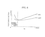
- valve drive friction that resists valve actuation tends to increase as the engine rotating speed Ne becomes extremely low, and in the extremely-low-speed region, the valve drive friction increases with increase in the temperature of the lubricating oil and thus with decrease in the viscosity of the lubricating oil, exhibiting a property opposite to that of ordinary friction.
- FIG. 7 illustrates the relationship between the intake camshaft driving torque applied to the intake camshaft 4 and the amount of split between the first and second intake valves 9 and 10, wherein the maximum torque is indicated by the solid line and the minimum torque by the dashed line.
- FIG. 7 reveals that when the valve closing timing of the second intake valve 10 is set at the position S 1 where the amount of slip is not large, the maximum torque required to drive the intake camshaft 4 and the torque amplitude, that is, the fluctuating load, are smaller than when the valve closing timing is set at the most retarded position where the amount of split is large.
- the second cam phase variable mechanism 31 should be controlled not to the most retarded position but to an appropriately retarded position which is advanced from the most retarded position, as stated above.
- the second cam phase variable mechanism 31 is preferably controlled to the position S 1 in FIG. 4 where the combustion is stabilized because reduction in the pumping loss due to the retarded valve closing timing of the second intake valve 10 is balanced well with the strengthened in-cylinder flow, which is achieved by the shifted valve open periods of the first and second intake valves 9 and 10, as well as with the actual compression ratio dependent on the valve closing timing, and also the fuel consumption is optimized because the valve drive friction is small.
- the second cam phase variable mechanism 31 may also be controlled to a position falling within the predetermined phase range including or close to the position S 1 . By controlling the second cam phase variable mechanism 31 in this manner, it is possible to balance reduction in the fuel cost with the operational performance of the engine 1 in the low-speed, low-load region, especially in the extremely-low-speed, extremely-low-load region.
- FIG. 7 shows the case in which only the intake cam drive torque is driven.
- both intake and exhaust cam drive torques are driven by crank.
- cam drive torques are added up together to be driven by crank, and therefore, the second cam phase variable mechanism 31 may be controlled on the basis of the sum of the driving torques.
- the second embodiment differs from the first embodiment in that the first and second cam phase variable mechanisms 30 and 31 are controlled by using a map shown in FIG. 8 , instead of the map shown in FIG. 2 . In the following, therefore, only the differences between the first and second embodiments will be explained.
- the operation control of the first and second cam phase variable mechanisms 30 and 31 is executed with the engine operating condition classified into the region X, which is identical 1 with the region X shown in FIG. 2 , the region A (low-speed, low-load region), which is identical with the region A shown in FIG. 2 , a high-load or high-speed region B' (high-load or high-speed region) in which the engine load or the engine rotating speed Ne is high, and a higher-speed region C' in which the engine rotating speed Ne is still higher.
- the first cam phase variable mechanism 30 is controlled to an appropriately retarded position while the second cam phase variable mechanism 31 is controlled to the most advanced position.
- the engine load indicated by the accelerator position information from the APS 62 is higher than or equal to the predetermined value L 1 and at the same time the engine rotating speed Ne is higher than or equal to the predetermined value N 1 and lower than the predetermined value N 2 , or when the engine rotating speed Ne is higher than or equal to the predetermined value N2 and lower than a predetermined value N 3
- the first cam phase variable mechanism 30 is controlled to an appropriately retarded position and the second cam phase variable mechanism 31 is controlled to the most advanced position.
- the first cam phase variable mechanism 30 is controlled to the most retarded position while the second cam phase variable mechanism 31 is controlled to the most advanced position, as in the aforementioned region X.
- the first cam phase variable mechanism 30 is controlled to the most retarded position and the second cam phase variable mechanism 31 is controlled to the most advanced position.
- the second cam phase variable mechanism 31 is preferentially controlled with the first cam phase variable mechanism 30 fixed at the most retarded position.
- the first cam phase variable mechanism 30 is preferentially controlled with the second cam phase variable mechanism 31 fixed at the most advanced position.
- the region C' in which the engine rotating speed Ne is still higher, such preference control is stopped and the first and second cam phase variable mechanisms 30 and 31 are fixed at the most retarded and advanced positions, respectively.
- the first and second intake valves 9 and 10 can be continuously and smoothly operated as desired to increase the overall valve open period, and it is possible to satisfactorily lower the pumping loss of the engine 1 while precisely controlling the intake manifold pressure, whereby the engine output can be improved and the fuel cost reduced.
- a vane-type hydraulic actuator conventionally known in the art, for example, is used for each of the first and second cam phase variable mechanisms 30 and 31.
- the cam phase variable mechanism to be used in the present invention is, however, not limited to a specific type, and a solenoid-operated actuator, for example, may be used instead.
- the mode of the preference control is also not limited to the aforementioned control mode in which, with one of the first and second cam phase variable mechanisms 30 and 31 controlled to a fixed phase of the most advanced or retarded angle, the other is preferentially subjected to variable control.
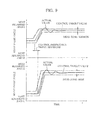
- FIG. 9 illustrates the relationship of control preference between the first cam phase variable mechanism (in FIG. 9 , indicated by "IST VVT") 30 and the second cam phase variable mechanism (in FIG. 9 , indicated by "2ND VVT”) 31. As seen from the control preference relationship illustrated in FIG.
- the two cam phase variable mechanisms 30 and 31 may be controlled to respective intermediate phases (control target values) set by target value setting means with their allowable deviation widths, or dead zones, set by dead zone setting means in such a manner that the dead zone for one of the two cam phase variable mechanisms is smaller in width (narrower) than the dead zone for the other cam phase variable mechanism.
- dead zones may be used such that the cam phase variable mechanism to be preferentially controlled is associated with a narrower dead zone.
- the control preference may be implemented by advancing the control instruction timing of one of the two cam phase variable mechanisms which is to be preferentially controlled, as illustrated in FIG. 9 .
- first and second cam phase variable mechanisms 30 and 31 can both be stably controlled with high precision.
Landscapes
- Engineering & Computer Science (AREA)
- Mechanical Engineering (AREA)
- General Engineering & Computer Science (AREA)
- Chemical & Material Sciences (AREA)
- Combustion & Propulsion (AREA)
- Output Control And Ontrol Of Special Type Engine (AREA)
- Valve Device For Special Equipments (AREA)
Abstract
Description
- The present invention relates to a variable valve device for internal combustion engines, and more particularly, to techniques for optimizing valve opening/closing timings of intake and exhaust valves.
- In recent years, more and more internal combustion engines (engines) have come to be equipped with cam phase variable mechanisms as a variable valve device for varying valve opening/closing timings (cam phases). Also, techniques have been developed whereby the cam phase variable mechanisms are applied to an engine having each cylinder provided with a plurality of intake valves and the valve opening/closing timings of all intake valves as well as only some of the intake valves are varied (split) in accordance with the operating condition of the engine (Japanese Laid-open Patent Publication No.
2009-144521 - Where the valve opening/closing timings of only some of the intake valves associated with the individual cylinders can be varied in this manner, the multiple intake valves can be made to open continuously as a whole, whereby highly flexible valve control can be executed so that the overall valve open period of the intake valves may be prolonged, making it possible to improve the operational performance of the engine.
- As actuators for such cam phase variable mechanisms, hydraulic actuators operated by means of operating oil pressure are generally used. Also in the aforementioned publication, a vane-type hydraulic actuator is used for an actuator for actuating all of the intake valves as well as for an actuator for actuating only some of the intake valves.
- Where a plurality of hydraulic actuators are used, however, a problem arises in that when the operating oil pressure is supplied to both of the hydraulic actuators at the same time, the supply pressure of the operating oil fluctuates due to temporary drop in the overall operating oil pressure. Such fluctuation in the supply pressure of the operating oil is not desirable because the valve opening/closing timings (cam phases) possibly fail to be accurately controlled as a result.
- An object of the present invention is to provide a variable valve device for an internal combustion engine which is capable of precisely controlling cam phases, thereby improving operational performance of the engine.
- To achieve the object, the present invention provides a variable valve device for an internal combustion engine including cylinders each provided with a first intake valve actuated by is first intake cam and a second intake valve actuated by a second intake cam, the variable valve device including a first cam phase variable mechanism capable of varying phases of both the first and second intake cams, and a second cam phase variable mechanism capable of varying the phase of the second intake cam relative to that of the first intake cam, characterized in that the variable valve device further comprises phase variable control unit that controls the first and second cam phase variable mechanisms, and the phase variable control unit preferentially controls one of the first and second cam phase variable mechanisms over the other in accordance with an operating condition of the engine.
- Thus, the variable valve device for an internal combustion engine is provided with the first cam phase variable mechanism capable of varying the phases of both the first and second intake cams by using operating oil pressure, and also with the second cam phase variable mechanism having a split change function and capable of retarding the phase of the second intake cam relative to that of the first intake cam by using the operating oil pressure, and one of the first and second cam phase variable mechanisms is preferentially controlled over the other in accordance with the operating condition of the engine. Accordingly, the first or second cam phase variable mechanism can be stably controlled in accordance with the operating condition of the engine, so that the phase of the first or second intake cam can be controlled with high precision to improve the output of the engine and also reduce the fuel cost, making it possible to improve the operational performance of the engine.
- Preferably, the phase variable control unit preferentially controls one of the first and second cam phase variable mechanisms over the other in accordance with a region in which the engine is operating and which is determined by at least one of rotating speed and load of the engine.
- Thus, the first or second cam phase variable mechanism can be stably controlled in accordance with the rotating speed and load of the engine, so that the phase of the first or second intake cam can be precisely controlled to improve the engine output and also reduce the fuel cost, thereby making it possible to improve the operational performance of the engine.
- Preferably, the phase variable control unit preferentially controls the second cam phase variable mechanism when the engine is operating in a low-speed, low-load region in which the rotating speed is lower than a predetermined rotating speed and also the load is lower than a predetermined load.
- For example, when the engine is operating in the low-speed, low-load region, the first cam phase variable mechanism is not controlled with the supply of the operating oil pressure stopped, and the operating oil pressure is supplied only to the second cam phase variable mechanism.
- Consequently, fluctuations in the supply pressure of the operating oil can be suppressed in the low-speed, low-load region, thus permitting stable control of the second cam phase variable mechanism. The phase of the second intake cam can therefore be precisely controlled to improve the output of the engine and also reduce the fuel cost, whereby the operational performance of the engine can be improved.
- Preferably, the engine includes a throttle valve arranged in an intake passage thereof and capable of adjusting the amount of intake air, and the phase variable control unit preferentially controls the first cam phase variable mechanism when the engine is operating in a high-load region in which the load is higher than or equal to the predetermined load.
- For example, when the engine is operating in the high-load region, the second cam phase variable mechanism is not controlled with the supply of the operating oil pressure stopped, and the operating oil pressure is supplied only to the first cam phase variable mechanism.
- Consequently, fluctuations in the supply pressure of the operating oil can be suppressed also in the high-load region, thus permitting stable control of the first cam phase variable mechanism. The phase of the first intake cam can therefore be precisely controlled to improve the output of the engine and also reduce the fuel cost, so that the operational performance of the engine can be improved.
- Preferably, the phase variable control unit stops preferentially controlling one of the first and second cam phase variable mechanisms over the other when the engine is operating in a high-speed region in which the rotating speed is higher than or equal to the predetermined rotating speed.
- For example, when the engine is operating in the high-speed region, the first cam phase variable mechanism is fixed at the most retarded position and the second cam phase variable mechanism is fixed at the most advanced position.
- Consequently, fluctuations in the supply pressure of the operating oil can be suppressed also in the high-speed region, permitting stable control of the first cam phase variable mechanism. The phase of the first intake cam can therefore be precisely controlled to improve the engine output and also reduce the fuel cost, whereby the operational performance of the engine can be improved.
- preferably, the phase variable control unit includes target value setting unit that sets a control target value for each of the first and second cam phase variable mechanisms, and dead zone setting unit that sets a dead zone with respect to each of the control target values set by the target value setting unit, wherein the dead zone setting unit sets the dead zones such that the dead zone associated with one of the first and second cam phase variable mechanisms which is to be preferentially controlled is narrower than the dead zone associated with the other of the first and second cam phase variable mechanisms.
- Also in this case, the first or second cam phase variable mechanism can be stably controlled, so that the phase of the first or second intake cam can be precisely controlled to improve the engine output and also reduce the fuel cost, making it possible to improve the operational performance of the engine.
- Preferably, the phase variable control unit advances control start timing of one of the first and second cam phase variable mechanisms which is to be preferentially controlled over the other.
- Also in this case, it is possible to stably control the first or second cam phase variable mechanism, so that the phase of the first or second intake cam can be precisely controlled to improve the output of the engine and also reduce the fuel cost, thus improving the operational performance of the engine.
- The present invention will become more fully understood from the detailed description given hereinafter and the accompanying drawings which are given by way of illustration only, and thus, are not limitative of the present invention, and wherein:
-
FIG. 1 illustrates a schematic construction of a variable valve device for an internal combustion engine according to the present invention; -
FIG. 2 illustrates a map used for controlling the operations of first and second cam phase variable mechanisms according to a first embodiment; -
FIGS. 3(a) ,3(b) and3(c) individually illustrate the relationship of the crank angle of the engine with the lift amounts of first and second intake valves and an exhaust valve during the execution of operation control in a low-speed, low-load region; -
FIG. 4 illustrates the relationship of the valve closing timing of the second intake valve with combustion stability, intake manifold pressure, pumping loss, and fuel consumption; -
FIG. 5 is a Stribeck diagram; -
FIG. 6 illustrates the relationship of engine rotating speed Ne with valve drive friction and lubricating oil temperature; -
FIG. 7 illustrates the relationship of the amount of split between the first and second intake valves with torque applied to an intake camshaft; -
FIG. 8 illustrates a map used for controlling the operations of the first and second cam phase variable mechanisms according to a second embodiment; and -
FIG. 9 illustrates the relationship of control preference between the first and second cam phase variable mechanisms. - Embodiments of the present invention will be hereinafter described with reference to the accompanying drawings.
- A first embodiment will be explained first.
-
FIG. 1 schematically illustrates the construction of a variable valve device for an internal combustion engine according to the present invention. More particularly,FIG. 1 is a top view showing the internal structure of acylinder head 2 of an engine 1. - The engine 1 is an in-line four-cylinder engine with a DOHC valve train, for example. As shown in
FIG. 1 , cam sprockets 5 and 6 are connected to exhaust andintake camshafts cylinder head 2, and are also coupled to a crankshaft, not shown, by a chain 7. - Each cylinder 8 of the engine 1 is provided with two
intake valves 9 and 10 and two exhaust valves, not shown. The twointake valves 9 and 10 are actuated by first andsecond intake cams intake camshaft 4. Specifically, out of the two intake valves, thefirst intake valve 9 is actuated by thefirst intake cam 11, and the second intake valve 10 by thesecond intake cam 12. The two exhaust valves, on the other hand, are actuated byrespective exhaust cams 13 fixed on theexhaust camshaft 3. - The
intake camshaft 4 has a double structure comprising a hollow outer camshaft and an inner camshaft inserted through the outer camshaft. The outer and inner camshafts are coaxially arranged with some gap therebetween and are rotatably supported by a plurality ofcam journals 23 formed on thecylinder head 2 of the engine 1. - The
first intake cams 11 are fixed on the outer camshaft, while thesecond intake cams 12 are rotatably supported on the outer camshaft. Thesecond intake cams 12 are fixed to the inner camshaft by fixing pins fitted through circumferentially elongated holes formed through the outer camshaft. Consequently, thefirst intake cams 11 are driven by rotation of the outer camshaft, while thesecond intake cams 12 are driven by rotation of the inner camshaft. - The
intake camshaft 4 is provided with a first camphase variable mechanism 30 and a second camphase variable mechanism 31. For each of the first and second camphase variable mechanisms hydraulic unit 50 via a solenoid-operatedhydraulic valve - The first cam
phase variable mechanism 30 is attached to the front end of theintake camshaft 4 with the housing fixed to the cam sprocket 6 and with the vane rotor fixed to the outer camshaft. - The second cam
phase variable mechanism 31 is attached to the rear end of theintake camshaft 4, and the outer and inner camshafts are fixed, respectively, to the housing and the vane rotor of the second camphase variable mechanism 31. - Because of the construction described above, the first cam phase
variable mechanism 30 provides the function of varying the rotational angle of the outer camshaft relative to the cam sprocket 6, while the second cam phasevariable mechanism 31 provides the function of varying the rotational angle of the inner camshaft relative to the outer camshaft. Specifically, the first cam phasevariable mechanism 30 has the function of varying the valve opening/closing timing of the first andsecond intake valves 9 and 10 as a whole with respect to the valve opening/closing timing of the exhaust valves, and the second cam phasevariable mechanism 31 has a split change function, namely, the function of varying a phase difference (amount of split) between the valve opening/closing timings of the first andsecond intake valves 9 and 10. - A
first cam sensor 32 for detecting an actual rotational angle of the outer camshaft is mounted to thecylinder head 2. In accordance with information from thefirst cam sensor 32, the opening of thehydraulic valve 52 is adjusted so as to control the operation of the first cam phasevariable mechanism 30. - The rear end of the
intake camshaft 4 penetrates through arear wall 2a of thecylinder head 2, and thus the second cam phasevariable mechanism 31 is located outside thecylinder head 2. The second cam phasevariable mechanism 31 is covered with anactuator cover 40. - To the
actuator cover 40 is mounted asecond cam sensor 45, which detects the rotation timing of the vane rotor of the second cam phasevariable mechanism 31 to detect an actual rotational angle of the inner camshaft. - Accordingly, an actual rotational angle difference between the inner and outer camshafts can be detected from the information provided by the first and
second cam sensors hydraulic valve 54 is adjusted on the basis of the actual rotational angle difference, whereby the operation of the second cam phasevariable mechanism 31 can be controlled. - An electronic control unit (ECU) 60 is a controller for performing various control operations on the engine 1 and comprises a CPU, memories, and so forth. Various sensors including an accelerator position sensor (APS) 62 for detecting the position of an accelerator of the engine 1 and a
crank angle sensor 64 for detecting the crank angle of the engine 1, besides the first andsecond cam sensors ECU 60. Various devices including athrottle valve 66 arranged in the intake passage of the engine 1 for adjusting the amount of intake air, in addition to the solenoid-operatedhydraulic valves ECU 60. Based on information about the accelerator position detected by theAPS 62, engine load is detected, and based on information about the crank angle detected by thecrank angle sensor 64, engine rotating speed Ne is detected. - The following describes the operation of the variable valve device of the first embodiment of the present invention configured in the manner described above.
- The operation of the first and second cam phase
variable mechanisms ECU 60 in accordance with a map illustrated inFIG. 2 , that is, in accordance with the operating condition of the engine 1 represented by the engine load and the engine rotating speed Ne (phase variable control unit). - As seen from the map of
FIG. 2 , the operation control of the first and second cam phasevariable mechanisms - In the region X corresponding to the start and warm-up of the engine 1, the or pressure supplied from the
hydraulic unit 50 is not sufficiently high. Accordingly, the first cam phase variable mechanism (inFIG. 2 , indicated by "1ST VVT") 30 is held at the most retarded position, and the second cam phase variable mechanism (inFIG. 2 , indicated by "2ND VVT") 31 has its phase kept at the most advanced position by a locking pin. - In the region A, the first cam phase
variable mechanism 30 is controlled to the most retarded position while the second cam phasevariable mechanism 31 is controlled to an appropriate phase on the basis of the accelerator position information from theAPS 62, as distinct from the region X1 corresponding to the start and warm-up of the engine 1. Specifically, when the engine rotating speed Ne is equal to or higher than a predetermined value No and at the same time is lower than a predetermined value N1, the oil pressure supplied from thehydraulic unit 50 is still not sufficiently high, and thus the second cam phasevariable mechanism 31 is comparatively higher in controllability than the first cam phasevariable mechanism 30, because the second cam phasevariable mechanism 31 is configured to vary the phase of a fewer valves than the first cam phasevariable mechanism 30. Accordingly, the first cam phasevariable mechanism 30 is kept at the phase determined by the locking pin or is controlled to the most retarded position by the oil pressure, while the second cam phasevariable mechanism 31 is controlled to an arbitrary phase. Also, while the engine load is lower than a predetermined value L1 and the engine rotating speed Ne is equal to or higher than the predetermined value N1 and at the same time is lower than a predetermined value N2, the first cam phasevariable mechanism 30 is controlled to the most retarded position and the second cam phasevariable mechanism 31 is controlled to an appropriate phase. - In the region B, the first cam phase
variable mechanism 30 is controlled to an appropriately retarded position while the second cam phasevariable mechanism 31 is controlled to the most advanced position. Specifically, when the engine load indicated by the accelerator position information from theAPS 62 is equal to or higher than the predetermined value L1 and the engine rotating speed Ne is higher than or equal to the predetermined value N1 and at the same time is lower than the predetermined value N2, the first cam phasevariable mechanism 30 is controlled to an appropriately retarded position and the second cam phasevariable mechanism 31 is controlled to the most advanced position. - In the region C, the first cam phase
variable mechanism 30 is controlled to the most retarded position while the second cam phasevariable mechanism 31 is controlled to the most advanced position, as in the region X. Specifically, when the engine rotating speed Ne is equal to or higher than the predetermined value N2, the first cam phasevariable mechanism 30 is controlled to the most retarded position and the second cam phasevariable mechanism 31 is controlled to the most advanced position. - Thus, in the region A in which the engine load and the engine rotating speed Ne are both low, the second cam phase
variable mechanism 31 is preferentially controlled with the first cam phasevariable mechanism 30 fixed at the most retarded position. On the other hand, in the region B in which the engine load is high but the engine rotating speed Ne is low, the first cam phasevariable mechanism 30 is preferentially controlled with the second cam phasevariable mechanism 31 fixed at the most advanced position. In the region C in which the engine rotating speed Ne is high, such preference control is stopped and the first and second cam phasevariable mechanisms - In this manner, where one of the first and second cam phase
variable mechanisms variable mechanisms variable mechanisms variable mechanisms - Accordingly, the first and
second intake valves 9 and 10 can be continuously and smoothly operated as desired to increase the overall valve open period, and it is possible to satisfactorily lower the pumping loss of the engine 1 while precisely controlling the intake manifold pressure, whereby the engine output can be improved and the fuel cost reduced. - Meanwhile, in the region A in which the engine load and the engine rotating speed Ne are both low, the second cam phase
variable mechanism 31 is controlled in such a manner that themechanism 31 is controlled to the most retarded position in the central portion of the region A and is gradually advanced to an appropriately retarded position as the control point moves toward the peripheral portion of the region A away from the central portion, as indicated by the arrow. - Also, as indicated by the dashed line in
FIG. 2 , the region A is subdivided into a region A1 in which both the engine load and the engine rotating speed Ne are extremely low, and the remaining region A2. The region A1 denotes a post-warm-up extremely-low-speed, extremely-low-load region including a hot idling region, and the region A2 denotes an ordinary low-speed, low-load region. - The extremely-low-speed, extremely-low-load region A1 is situated in the peripheral portion of the region A distant from the central portion. Thus, in the extremely-low-speed, extremely-low-load region A1, the first cam phase
variable mechanism 30 is controlled to the most retarded position while the second cam phasevariable mechanism 31 is not controlled to the most retarded position but is advanced to an appropriately retarded position, as stated above. - Referring now to
FIGS. 3(a) ,3(b) and3(c) , there are illustrated the relationships of the crank angle of the engine 1 with the valve lift amounts of the first andsecond intake valves 9 and 10 and the exhaust valve during the execution of the operation control in the region A.FIG. 3(a) indicates the case where the second cam phasevariable mechanism 31 is controlled to the most advanced position to advance the valve closing timing of the second intake valve 10 so as to coincide with that of thefirst intake valve 9, as in the region X corresponding to the start and warm-up of the engine 1, for example, thereby increasing the actual compression ratio to enhance the ignition performance and thus the combustion stability.FIG. 3(b) indicates the case where the second cam phasevariable mechanism 31 is controlled to an appropriately retarded position in the extremely-low-speed, extremely-low-load region A1, to reduce the pumping loss by retarding the valve closing timing of the second intake valve, as well as to have the strengthened in-cylinder flow, caused by the shifted valve open periods of the first and second intake valves, balanced with the actual compression ratio dependent on the valve closing timing, so as to enhance the combustion stability and thereby improve the fuel consumption.FIG. 3(c) indicates the case where the second cam phasevariable mechanism 31 is controlled to the most retarded position in the central portion of the region A (region A2), to maximize the amount of split, that is, the phase difference between the valve opening/closing timings of the first andsecond intake valves 9 and 10, thereby minimizing the actual compression ratio by the retarded valve closing timing of the second intake valve, as well as the pumping loss, to strengthen the in-cylinder flow and thereby improve the fuel consumption. - Thus, in the extremely-low-speed, extremely-low-load region A1, the second cam phase
variable mechanism 31 is controlled not to the most retarded position but to an appropriately retarded position for the following reason: It was experimentally conformed that if the second cam phasevariable mechanism 31 is controlled to the most retarded position in the extremely-low-speed, extremely-low-load region to maximize the amount of split between the first andsecond intake valves 9 and 10, the combustion stability deteriorates instead of improving, so that the fuel consumption tends to lower correspondingly. - Referring now to
FIG. 4 , there is illustrated the relationship of the valve closing timing of the second intake valve 10 with the combustion stability, the pressure in the intake manifold (intake manifold pressure), the pumping loss and the fuel consumption, all based on experimental values.FIG. 4 reveals the following: By retarding the second cam phasevariable mechanism 31 and thus the valve closing timing of the second intake valve 10, it is possible to satisfactorily lower the pumping loss while at the same time precisely controlling the intake manifold pressure, but as the combustion stability deteriorates, the fuel consumption deteriorates. - The reason why the combustion stability and the fuel consumption deteriorate as the second cam phase
variable mechanism 31 is retarded in the extremely-low-speed, extremely-low-load region is presumably because, despite the pumping loss reducing effect, the combustion quality lowers due to reduction in the actual compression ratio, and also because the heat loss increases due to excessively strengthened in-cylinder flow. - Accordingly, in the extremely-low-speed, extremely-low-load region, the second cam phase
variable mechanism 31 is controlled not to the most retarded position but to an appropriately retarded position, for example, to a position S1 shown inFIG. 4 where the combustion stability and the fuel consumption are optimal, or to a position falling within a predetermined phase range including or close to the position S1. - In addition, where the second cam phase
variable mechanism 31 is controlled not to the most retarded position but to an appropriately retarded position such as the position S1 inFIG. 4 where the combustion stability and the fuel consumption are optimal, or to a position falling within the predetermined phase range including or close to the position S1, thethrottle valve 66 is also controlled toward the closed position. This leads to increase in the intake manifold pressure and thus in the negative pressure in the combustion chamber, whereby the vaporization of fuel is promoted, making it possible to further improve the combustion stability. - Deterioration in the combustion stability and the fuel consumption, which is encountered when the second cam phase
variable mechanism 31 is retarded in the extremely-low-speed, extremely-low-load region, is presumably caused also due to increase friction attributable to change in the state of lubrication of theintake camshaft 4 and theintake valves 9 and 10 lubricated by lubricating oil, as explained below. - Referring to
FIG. 5 , there is illustrated what is called a Stribeck diagram showing the relationship of the viscosity of lubricating oil, sliding velocity and fluctuating load {(viscosity) × (sliding velocity)/(fluctuating load)} with the state of lubrication. As seen fromFIG. 5 , the smaller the viscosity of the lubricating oil or the lower the sliding velocity or the larger the fluctuating load, the state of lubrication changes from fluid lubrication to mixed lubrication or further to boundary lubrication, with the result that the friction coefficient µ increases. - As shown in
FIG. 6 , valve drive friction that resists valve actuation tends to increase as the engine rotating speed Ne becomes extremely low, and in the extremely-low-speed region, the valve drive friction increases with increase in the temperature of the lubricating oil and thus with decrease in the viscosity of the lubricating oil, exhibiting a property opposite to that of ordinary friction. - The influence of the property will be explained with reference to
FIG. 5 . In the post-warm-up extremely-low-speed region, the sliding velocity is low because of low rotating speed Ne of the engine, and therefore, the lubrication state is liable to fall within the boundary lubrication or mixed lubrication. Since the lubrication state is liable to shift to the boundary lubrication or mixed lubrication as the temperature of the lubricating oil increases and thus the viscosity of the lubricating oil decreases, the friction coefficient µ creases, with the result that the valve drive friction increases. Consequently, the fuel consumption further deteriorates. - In addition, the load required to drive the
intake camshaft 4 is subject to fluctuation in the extremely-low-speed, extremely-low-load region.FIG. 7 illustrates the relationship between the intake camshaft driving torque applied to theintake camshaft 4 and the amount of split between the first andsecond intake valves 9 and 10, wherein the maximum torque is indicated by the solid line and the minimum torque by the dashed line.FIG. 7 reveals that when the valve closing timing of the second intake valve 10 is set at the position S1 where the amount of slip is not large, the maximum torque required to drive theintake camshaft 4 and the torque amplitude, that is, the fluctuating load, are smaller than when the valve closing timing is set at the most retarded position where the amount of split is large. - The phenomenon will be considered with reference to
FIG. 5 . In the most retarded position where the amount of split is large, the torque applied to drive theintake camshaft 4 is large, so that the fluctuating load is large. Accordingly, the lubrication state of the system for driving theintake camshaft 4 or of the parts supporting therotating intake camshaft 4 is liable to become boundary lubrication or mixed lubrication, with the result that the friction coefficient µ increases, increasing the valve drive friction and deteriorating the fuel consumption. On The other hand, in the position S1 where the split amount is not so large, the torque applied to drive theintake camshaft 4 is small, so that the fluctuating load is also small. Thus, the fluid lubrication is easily attained, and since the friction coefficient µ remains small, the valve drive friction is small, preventing deterioration in the fuel consumption. - Also for this reason, it is desirable that in the extremely-low-speed, extremely-low-load region, the second cam phase
variable mechanism 31 should be controlled not to the most retarded position but to an appropriately retarded position which is advanced from the most retarded position, as stated above. For example, the second cam phasevariable mechanism 31 is preferably controlled to the position S1 inFIG. 4 where the combustion is stabilized because reduction in the pumping loss due to the retarded valve closing timing of the second intake valve 10 is balanced well with the strengthened in-cylinder flow, which is achieved by the shifted valve open periods of the first andsecond intake valves 9 and 10, as well as with the actual compression ratio dependent on the valve closing timing, and also the fuel consumption is optimized because the valve drive friction is small. The second cam phasevariable mechanism 31 may also be controlled to a position falling within the predetermined phase range including or close to the position S1. By controlling the second cam phasevariable mechanism 31 in this manner, it is possible to balance reduction in the fuel cost with the operational performance of the engine 1 in the low-speed, low-load region, especially in the extremely-low-speed, extremely-low-load region. -
FIG. 7 shows the case in which only the intake cam drive torque is driven. In a DOHC-type engine, however, both intake and exhaust cam drive torques are driven by crank. Moreover, in a V-type engine, cam drive torques are added up together to be driven by crank, and therefore, the second cam phasevariable mechanism 31 may be controlled on the basis of the sum of the driving torques. - The second embodiment differs from the first embodiment in that the first and second cam phase
variable mechanisms FIG. 8 , instead of the map shown inFIG. 2 . In the following, therefore, only the differences between the first and second embodiments will be explained. - As seen from the map illustrated in
FIG. 8 , the operation control of the first and second cam phasevariable mechanisms FIG. 2 , the region A (low-speed, low-load region), which is identical with the region A shown inFIG. 2 , a high-load or high-speed region B' (high-load or high-speed region) in which the engine load or the engine rotating speed Ne is high, and a higher-speed region C' in which the engine rotating speed Ne is still higher. - The regions X and A are identical with the those already explained above, and therefore, description thereof is omitted.
- In the region B', the first cam phase
variable mechanism 30 is controlled to an appropriately retarded position while the second cam phasevariable mechanism 31 is controlled to the most advanced position. Specifically, when the engine load indicated by the accelerator position information from theAPS 62 is higher than or equal to the predetermined value L1 and at the same time the engine rotating speed Ne is higher than or equal to the predetermined value N1 and lower than the predetermined value N2, or when the engine rotating speed Ne is higher than or equal to the predetermined value N2 and lower than a predetermined value N3, the first cam phasevariable mechanism 30 is controlled to an appropriately retarded position and the second cam phasevariable mechanism 31 is controlled to the most advanced position. - On the other hand, in the region C', the first cam phase
variable mechanism 30 is controlled to the most retarded position while the second cam phasevariable mechanism 31 is controlled to the most advanced position, as in the aforementioned region X. Specifically, when the engine rotating speed Ne is higher than or equal to the predetermined value N3, the first cam phasevariable mechanism 30 is controlled to the most retarded position and the second cam phasevariable mechanism 31 is controlled to the most advanced position. - Thus, also in the second embodiment, in the region A in which the engine load and the engine rotating speed Ne are both low, the second cam phase
variable mechanism 31 is preferentially controlled with the first cam phasevariable mechanism 30 fixed at the most retarded position. In the region B' in which the engine load is high or the engine rotating speed Ne is high, the first cam phasevariable mechanism 30 is preferentially controlled with the second cam phasevariable mechanism 31 fixed at the most advanced position. In the region C' in which the engine rotating speed Ne is still higher, such preference control is stopped and the first and second cam phasevariable mechanisms - Consequently, like the first embodiment, fluctuations in the supply pressure of the operating oil can be suppressed in all of the regions A, B' and C', thus permitting stable and accurate control of both the first and second cam phase
variable mechanisms - Thus, also in the second embodiment, the first and
second intake valves 9 and 10 can be continuously and smoothly operated as desired to increase the overall valve open period, and it is possible to satisfactorily lower the pumping loss of the engine 1 while precisely controlling the intake manifold pressure, whereby the engine output can be improved and the fuel cost reduced. - In the description of the foregoing embodiments, it is stated that a vane-type hydraulic actuator conventionally known in the art, for example, is used for each of the first and second cam phase
variable mechanisms - The mode of the preference control is also not limited to the aforementioned control mode in which, with one of the first and second cam phase
variable mechanisms FIG. 9 illustrates the relationship of control preference between the first cam phase variable mechanism (inFIG. 9 , indicated by "IST VVT") 30 and the second cam phase variable mechanism (inFIG. 9 , indicated by "2ND VVT") 31. As seen from the control preference relationship illustrated inFIG. 9 , the two cam phasevariable mechanisms FIG. 9 . - Also in this case, the first and second cam phase
variable mechanisms
Claims (7)
- A variable valve device for an internal combustion engine including cylinders (8) each provided with a first intake valve (9) actuated by a first intake cam (11) and a second intake valve (10) actuated by a second intake cam (12), the variable valve device including a first cam phase variable mechanism (30) capable of varying phases of both the first and second intake cams, and a second cam phase variable mechanism (31) capable of varying the phase of the second intake cam relative to that of the first intake cam,
characterized in that the variable valve device further comprises phase variable control unit (60) that controls the first and second cam phase variable mechanisms,
the phase variable control unit preferentially controls one of the first and second cam phase variable mechanisms over the other in accordance with an operating condition of the engine (1). - The variable valve device according to claim 1, characterized in that the phase variable control unit (60) preferentially controls one of the first and second cam phase variable mechanisms (30; 31) over the other in accordance with a region in which the engine (1) is operating and which is determined by at least one of rotating speed and load of the engine.
- The variable valve device according to claim 2, characterized in that the phase variable control unit (60) preferentially controls the second cam phase variable mechanism (31) when the engine (1) is operating in a low-speed, low-load region in which the rotating speed is lower than a predetermined rotating speed and also the load is lower than a predetermined load.
- The variable valve device according to claim 3, characterized in that the phase variable control unit (60) preferentially controls the first cam phase variable mechanism (30) when the engine (1) is operating in a high-load region in which the load is higher than or equal to the predetermined load.
- The variable valve device according to claim 3 or 4, characterized in that the phase variable control unit (60) stops preferentially controlling one of the first and second cam phase variable mechanisms (30; 31) over the other when the engine (1) is operating in a high-speed region in which the rotating speed is higher than or equal to the predetermined rotating speed.
- The variable valve device according to any one of claims 1 to 5, characterized in that the phase variable control unit (60) includes:target value setting unit that sets a control target value for each of the first and second cam phase variable mechanisms (30; 31); anddead zone setting unit that sets a dead zone with respect to each of the control target values set by the target value setting unit,wherein the dead zone setting unit sets the dead zones such that the dead zone associated with one of the first and second cam phase variable mechanisms which is to be preferentially controlled is narrower than the dead zone associated with the other of the first and second cam phase variable mechanisms.
- The variable valve device according to any one of claims 1 to 5, characterized in that the phase variable control unit (60) advances control start timing of one of the first and second cam phase variable mechanisms (30; 31) which is to be preferentially controlled over the other.
Applications Claiming Priority (1)
| Application Number | Priority Date | Filing Date | Title |
|---|---|---|---|
| JP2009254910A JP5093521B2 (en) | 2009-11-06 | 2009-11-06 | Variable valve operating device for internal combustion engine |
Publications (2)
| Publication Number | Publication Date |
|---|---|
| EP2320035A1 true EP2320035A1 (en) | 2011-05-11 |
| EP2320035B1 EP2320035B1 (en) | 2014-04-30 |
Family
ID=43587295
Family Applications (1)
| Application Number | Title | Priority Date | Filing Date |
|---|---|---|---|
| EP10190188.2A Not-in-force EP2320035B1 (en) | 2009-11-06 | 2010-11-05 | Variable valve device for internal combustion engine |
Country Status (5)
| Country | Link |
|---|---|
| US (1) | US8991342B2 (en) |
| EP (1) | EP2320035B1 (en) |
| JP (1) | JP5093521B2 (en) |
| KR (1) | KR101204558B1 (en) |
| CN (1) | CN102052117B (en) |
Cited By (3)
| Publication number | Priority date | Publication date | Assignee | Title |
|---|---|---|---|---|
| WO2014071927A1 (en) * | 2012-11-12 | 2014-05-15 | Schaeffler Technologies AG & Co. KG | Camshaft adjustment device |
| CN106968741A (en) * | 2015-12-10 | 2017-07-21 | 现代自动车株式会社 | The system and method for controlling the valve timing of CVVD engines |
| CN107201923A (en) * | 2016-03-16 | 2017-09-26 | 现代自动车株式会社 | The control system and method for the valve timing of continuous variable valve duration engine |
Families Citing this family (5)
| Publication number | Priority date | Publication date | Assignee | Title |
|---|---|---|---|---|
| JP5985286B2 (en) * | 2012-07-17 | 2016-09-06 | 日立オートモティブシステムズ株式会社 | Variable valve operating device for internal combustion engine |
| US10202911B2 (en) * | 2013-07-10 | 2019-02-12 | Ford Global Technologies, Llc | Method and system for an engine for detection and mitigation of insufficient torque |
| KR101558384B1 (en) * | 2014-04-02 | 2015-10-07 | 현대자동차 주식회사 | Valve Train Layout Structure Including Return Spring and Camshaft-In-Camshaft |
| US9752464B2 (en) | 2014-05-28 | 2017-09-05 | Ford Global Technologies, Llc | Supercharged applied ignition internal combustion engine with exhaust-gas turbocharging and method for operating an internal combustion engine of said type |
| JP7115028B2 (en) * | 2018-05-22 | 2022-08-09 | マツダ株式会社 | Compression ignition engine controller |
Citations (6)
| Publication number | Priority date | Publication date | Assignee | Title |
|---|---|---|---|---|
| EP0582846A1 (en) | 1992-08-13 | 1994-02-16 | Bayerische Motoren Werke Aktiengesellschaft | Internal combustion piston engine with gas exchange valves per cylinder |
| GB2369175A (en) | 2000-11-18 | 2002-05-22 | Mechadyne Plc | Variable phase coupling |
| DE102005039751A1 (en) | 2005-08-23 | 2007-03-01 | Mahle International Gmbh | camshaft |
| US20070272183A1 (en) * | 2006-05-27 | 2007-11-29 | Mahle International Gmbh | Camshaft |
| WO2008087539A2 (en) | 2007-01-19 | 2008-07-24 | Toyota Jidosha Kabushiki Kaisha | Hydraulic actuator control device and hydraulic actuator control method |
| US20090145380A1 (en) * | 2007-12-07 | 2009-06-11 | Denso Corporation | Apparatus for controlling variable valve device |
Family Cites Families (5)
| Publication number | Priority date | Publication date | Assignee | Title |
|---|---|---|---|---|
| JP4147917B2 (en) * | 2002-11-28 | 2008-09-10 | トヨタ自動車株式会社 | Electromagnetic drive valve control device and electromagnetic drive valve control method for internal combustion engine |
| JP4202297B2 (en) * | 2004-05-20 | 2008-12-24 | 株式会社日立製作所 | Valve timing control device for internal combustion engine |
| JP4747158B2 (en) | 2007-12-11 | 2011-08-17 | 本田技研工業株式会社 | Valve operating apparatus provided with phase control means |
| JP2009221867A (en) * | 2008-03-13 | 2009-10-01 | Honda Motor Co Ltd | Internal combustion engine having sub combustion chamber and exhaust recirculation passage |
| JP2009228640A (en) * | 2008-03-25 | 2009-10-08 | Honda Motor Co Ltd | Valve train for engine |
-
2009
- 2009-11-06 JP JP2009254910A patent/JP5093521B2/en not_active Expired - Fee Related
-
2010
- 2010-11-05 KR KR1020100109733A patent/KR101204558B1/en not_active Expired - Fee Related
- 2010-11-05 US US12/940,094 patent/US8991342B2/en not_active Expired - Fee Related
- 2010-11-05 EP EP10190188.2A patent/EP2320035B1/en not_active Not-in-force
- 2010-11-08 CN CN2010105366938A patent/CN102052117B/en not_active Expired - Fee Related
Patent Citations (6)
| Publication number | Priority date | Publication date | Assignee | Title |
|---|---|---|---|---|
| EP0582846A1 (en) | 1992-08-13 | 1994-02-16 | Bayerische Motoren Werke Aktiengesellschaft | Internal combustion piston engine with gas exchange valves per cylinder |
| GB2369175A (en) | 2000-11-18 | 2002-05-22 | Mechadyne Plc | Variable phase coupling |
| DE102005039751A1 (en) | 2005-08-23 | 2007-03-01 | Mahle International Gmbh | camshaft |
| US20070272183A1 (en) * | 2006-05-27 | 2007-11-29 | Mahle International Gmbh | Camshaft |
| WO2008087539A2 (en) | 2007-01-19 | 2008-07-24 | Toyota Jidosha Kabushiki Kaisha | Hydraulic actuator control device and hydraulic actuator control method |
| US20090145380A1 (en) * | 2007-12-07 | 2009-06-11 | Denso Corporation | Apparatus for controlling variable valve device |
Cited By (4)
| Publication number | Priority date | Publication date | Assignee | Title |
|---|---|---|---|---|
| WO2014071927A1 (en) * | 2012-11-12 | 2014-05-15 | Schaeffler Technologies AG & Co. KG | Camshaft adjustment device |
| CN106968741A (en) * | 2015-12-10 | 2017-07-21 | 现代自动车株式会社 | The system and method for controlling the valve timing of CVVD engines |
| CN107201923A (en) * | 2016-03-16 | 2017-09-26 | 现代自动车株式会社 | The control system and method for the valve timing of continuous variable valve duration engine |
| CN107201923B (en) * | 2016-03-16 | 2020-12-22 | 现代自动车株式会社 | System and method for controlling valve timing of a continuously variable valve duration engine |
Also Published As
| Publication number | Publication date |
|---|---|
| KR101204558B1 (en) | 2012-11-23 |
| JP5093521B2 (en) | 2012-12-12 |
| KR20110050380A (en) | 2011-05-13 |
| CN102052117A (en) | 2011-05-11 |
| US20110107992A1 (en) | 2011-05-12 |
| EP2320035B1 (en) | 2014-04-30 |
| CN102052117B (en) | 2013-11-13 |
| JP2011099392A (en) | 2011-05-19 |
| US8991342B2 (en) | 2015-03-31 |
Similar Documents
| Publication | Publication Date | Title |
|---|---|---|
| EP2320035B1 (en) | Variable valve device for internal combustion engine | |
| US6425357B2 (en) | Variable valve drive mechanism and intake air amount control apparatus of internal combustion engine | |
| JP6163831B2 (en) | Engine oil supply device | |
| JP4989523B2 (en) | Variable valve system for internal combustion engine and control device for internal combustion engine | |
| KR101396736B1 (en) | Internal combustion engine with variable valve gear | |
| RU147332U1 (en) | ENGINE SYSTEM | |
| EP2320038B1 (en) | Variable valve device for internal combustion engine | |
| US9260986B2 (en) | Oil pressure scheduling based on engine acceleration | |
| US20100116231A1 (en) | Variable valve gear for internal combustion engine | |
| JP5966999B2 (en) | Multi-cylinder engine controller | |
| EP2320034B1 (en) | Variable valve device for internal combustion engine | |
| RU2511875C1 (en) | Internal combustion engine with spark ignition | |
| EP2634407A1 (en) | Camshaft position determination system | |
| JP6020307B2 (en) | Multi-cylinder engine controller | |
| JPH10331612A (en) | Fuel injection control device for internal combustion engine | |
| US7467611B2 (en) | Rate limiting and balancing control system for dual independent camshaft phasing | |
| JPH11190235A (en) | Control device for internal combustion engine with variable valve mechanism |
Legal Events
| Date | Code | Title | Description |
|---|---|---|---|
| PUAI | Public reference made under article 153(3) epc to a published international application that has entered the european phase |
Free format text: ORIGINAL CODE: 0009012 |
|
| 17P | Request for examination filed |
Effective date: 20101201 |
|
| AK | Designated contracting states |
Kind code of ref document: A1 Designated state(s): AL AT BE BG CH CY CZ DE DK EE ES FI FR GB GR HR HU IE IS IT LI LT LU LV MC MK MT NL NO PL PT RO RS SE SI SK SM TR |
|
| AX | Request for extension of the european patent |
Extension state: BA ME |
|
| 17Q | First examination report despatched |
Effective date: 20120119 |
|
| GRAP | Despatch of communication of intention to grant a patent |
Free format text: ORIGINAL CODE: EPIDOSNIGR1 |
|
| INTG | Intention to grant announced |
Effective date: 20131112 |
|
| GRAS | Grant fee paid |
Free format text: ORIGINAL CODE: EPIDOSNIGR3 |
|
| GRAA | (expected) grant |
Free format text: ORIGINAL CODE: 0009210 |
|
| AK | Designated contracting states |
Kind code of ref document: B1 Designated state(s): AL AT BE BG CH CY CZ DE DK EE ES FI FR GB GR HR HU IE IS IT LI LT LU LV MC MK MT NL NO PL PT RO RS SE SI SK SM TR |
|
| REG | Reference to a national code |
Ref country code: CH Ref legal event code: EP Ref country code: GB Ref legal event code: FG4D |
|
| REG | Reference to a national code |
Ref country code: AT Ref legal event code: REF Ref document number: 665304 Country of ref document: AT Kind code of ref document: T Effective date: 20140515 |
|
| REG | Reference to a national code |
Ref country code: IE Ref legal event code: FG4D |
|
| REG | Reference to a national code |
Ref country code: DE Ref legal event code: R096 Ref document number: 602010015537 Country of ref document: DE Effective date: 20140612 |
|
| REG | Reference to a national code |
Ref country code: AT Ref legal event code: MK05 Ref document number: 665304 Country of ref document: AT Kind code of ref document: T Effective date: 20140430 |
|
| REG | Reference to a national code |
Ref country code: LT Ref legal event code: MG4D |
|
| REG | Reference to a national code |
Ref country code: NL Ref legal event code: VDEP Effective date: 20140430 |
|
| PG25 | Lapsed in a contracting state [announced via postgrant information from national office to epo] |
Ref country code: NL Free format text: LAPSE BECAUSE OF FAILURE TO SUBMIT A TRANSLATION OF THE DESCRIPTION OR TO PAY THE FEE WITHIN THE PRESCRIBED TIME-LIMIT Effective date: 20140430 Ref country code: IS Free format text: LAPSE BECAUSE OF FAILURE TO SUBMIT A TRANSLATION OF THE DESCRIPTION OR TO PAY THE FEE WITHIN THE PRESCRIBED TIME-LIMIT Effective date: 20140830 Ref country code: CY Free format text: LAPSE BECAUSE OF FAILURE TO SUBMIT A TRANSLATION OF THE DESCRIPTION OR TO PAY THE FEE WITHIN THE PRESCRIBED TIME-LIMIT Effective date: 20140430 Ref country code: NO Free format text: LAPSE BECAUSE OF FAILURE TO SUBMIT A TRANSLATION OF THE DESCRIPTION OR TO PAY THE FEE WITHIN THE PRESCRIBED TIME-LIMIT Effective date: 20140730 Ref country code: GR Free format text: LAPSE BECAUSE OF FAILURE TO SUBMIT A TRANSLATION OF THE DESCRIPTION OR TO PAY THE FEE WITHIN THE PRESCRIBED TIME-LIMIT Effective date: 20140731 Ref country code: LT Free format text: LAPSE BECAUSE OF FAILURE TO SUBMIT A TRANSLATION OF THE DESCRIPTION OR TO PAY THE FEE WITHIN THE PRESCRIBED TIME-LIMIT Effective date: 20140430 Ref country code: BG Free format text: LAPSE BECAUSE OF FAILURE TO SUBMIT A TRANSLATION OF THE DESCRIPTION OR TO PAY THE FEE WITHIN THE PRESCRIBED TIME-LIMIT Effective date: 20140730 Ref country code: FI Free format text: LAPSE BECAUSE OF FAILURE TO SUBMIT A TRANSLATION OF THE DESCRIPTION OR TO PAY THE FEE WITHIN THE PRESCRIBED TIME-LIMIT Effective date: 20140430 |
|
| PG25 | Lapsed in a contracting state [announced via postgrant information from national office to epo] |
Ref country code: ES Free format text: LAPSE BECAUSE OF FAILURE TO SUBMIT A TRANSLATION OF THE DESCRIPTION OR TO PAY THE FEE WITHIN THE PRESCRIBED TIME-LIMIT Effective date: 20140430 Ref country code: PL Free format text: LAPSE BECAUSE OF FAILURE TO SUBMIT A TRANSLATION OF THE DESCRIPTION OR TO PAY THE FEE WITHIN THE PRESCRIBED TIME-LIMIT Effective date: 20140430 Ref country code: AT Free format text: LAPSE BECAUSE OF FAILURE TO SUBMIT A TRANSLATION OF THE DESCRIPTION OR TO PAY THE FEE WITHIN THE PRESCRIBED TIME-LIMIT Effective date: 20140430 Ref country code: LV Free format text: LAPSE BECAUSE OF FAILURE TO SUBMIT A TRANSLATION OF THE DESCRIPTION OR TO PAY THE FEE WITHIN THE PRESCRIBED TIME-LIMIT Effective date: 20140430 Ref country code: SE Free format text: LAPSE BECAUSE OF FAILURE TO SUBMIT A TRANSLATION OF THE DESCRIPTION OR TO PAY THE FEE WITHIN THE PRESCRIBED TIME-LIMIT Effective date: 20140430 Ref country code: RS Free format text: LAPSE BECAUSE OF FAILURE TO SUBMIT A TRANSLATION OF THE DESCRIPTION OR TO PAY THE FEE WITHIN THE PRESCRIBED TIME-LIMIT Effective date: 20140430 Ref country code: HR Free format text: LAPSE BECAUSE OF FAILURE TO SUBMIT A TRANSLATION OF THE DESCRIPTION OR TO PAY THE FEE WITHIN THE PRESCRIBED TIME-LIMIT Effective date: 20140430 |
|
| PG25 | Lapsed in a contracting state [announced via postgrant information from national office to epo] |
Ref country code: PT Free format text: LAPSE BECAUSE OF FAILURE TO SUBMIT A TRANSLATION OF THE DESCRIPTION OR TO PAY THE FEE WITHIN THE PRESCRIBED TIME-LIMIT Effective date: 20140901 |
|
| PG25 | Lapsed in a contracting state [announced via postgrant information from national office to epo] |
Ref country code: RO Free format text: LAPSE BECAUSE OF FAILURE TO SUBMIT A TRANSLATION OF THE DESCRIPTION OR TO PAY THE FEE WITHIN THE PRESCRIBED TIME-LIMIT Effective date: 20140430 Ref country code: EE Free format text: LAPSE BECAUSE OF FAILURE TO SUBMIT A TRANSLATION OF THE DESCRIPTION OR TO PAY THE FEE WITHIN THE PRESCRIBED TIME-LIMIT Effective date: 20140430 Ref country code: CZ Free format text: LAPSE BECAUSE OF FAILURE TO SUBMIT A TRANSLATION OF THE DESCRIPTION OR TO PAY THE FEE WITHIN THE PRESCRIBED TIME-LIMIT Effective date: 20140430 Ref country code: DK Free format text: LAPSE BECAUSE OF FAILURE TO SUBMIT A TRANSLATION OF THE DESCRIPTION OR TO PAY THE FEE WITHIN THE PRESCRIBED TIME-LIMIT Effective date: 20140430 Ref country code: BE Free format text: LAPSE BECAUSE OF FAILURE TO SUBMIT A TRANSLATION OF THE DESCRIPTION OR TO PAY THE FEE WITHIN THE PRESCRIBED TIME-LIMIT Effective date: 20140430 Ref country code: SK Free format text: LAPSE BECAUSE OF FAILURE TO SUBMIT A TRANSLATION OF THE DESCRIPTION OR TO PAY THE FEE WITHIN THE PRESCRIBED TIME-LIMIT Effective date: 20140430 |
|
| REG | Reference to a national code |
Ref country code: DE Ref legal event code: R097 Ref document number: 602010015537 Country of ref document: DE |
|
| PLBE | No opposition filed within time limit |
Free format text: ORIGINAL CODE: 0009261 |
|
| STAA | Information on the status of an ep patent application or granted ep patent |
Free format text: STATUS: NO OPPOSITION FILED WITHIN TIME LIMIT |
|
| PG25 | Lapsed in a contracting state [announced via postgrant information from national office to epo] |
Ref country code: IT Free format text: LAPSE BECAUSE OF FAILURE TO SUBMIT A TRANSLATION OF THE DESCRIPTION OR TO PAY THE FEE WITHIN THE PRESCRIBED TIME-LIMIT Effective date: 20140430 |
|
| 26N | No opposition filed |
Effective date: 20150202 |
|
| REG | Reference to a national code |
Ref country code: DE Ref legal event code: R097 Ref document number: 602010015537 Country of ref document: DE Effective date: 20150202 |
|
| PG25 | Lapsed in a contracting state [announced via postgrant information from national office to epo] |
Ref country code: LU Free format text: LAPSE BECAUSE OF FAILURE TO SUBMIT A TRANSLATION OF THE DESCRIPTION OR TO PAY THE FEE WITHIN THE PRESCRIBED TIME-LIMIT Effective date: 20141105 Ref country code: MC Free format text: LAPSE BECAUSE OF FAILURE TO SUBMIT A TRANSLATION OF THE DESCRIPTION OR TO PAY THE FEE WITHIN THE PRESCRIBED TIME-LIMIT Effective date: 20140430 |
|
| REG | Reference to a national code |
Ref country code: CH Ref legal event code: PL |
|
| GBPC | Gb: european patent ceased through non-payment of renewal fee |
Effective date: 20141105 |
|
| PG25 | Lapsed in a contracting state [announced via postgrant information from national office to epo] |
Ref country code: SI Free format text: LAPSE BECAUSE OF FAILURE TO SUBMIT A TRANSLATION OF THE DESCRIPTION OR TO PAY THE FEE WITHIN THE PRESCRIBED TIME-LIMIT Effective date: 20140430 Ref country code: CH Free format text: LAPSE BECAUSE OF NON-PAYMENT OF DUE FEES Effective date: 20141130 Ref country code: LI Free format text: LAPSE BECAUSE OF NON-PAYMENT OF DUE FEES Effective date: 20141130 |
|
| REG | Reference to a national code |
Ref country code: IE Ref legal event code: MM4A |
|
| REG | Reference to a national code |
Ref country code: FR Ref legal event code: PLFP Year of fee payment: 6 |
|
| PG25 | Lapsed in a contracting state [announced via postgrant information from national office to epo] |
Ref country code: GB Free format text: LAPSE BECAUSE OF NON-PAYMENT OF DUE FEES Effective date: 20141105 Ref country code: IE Free format text: LAPSE BECAUSE OF NON-PAYMENT OF DUE FEES Effective date: 20141105 |
|
| PG25 | Lapsed in a contracting state [announced via postgrant information from national office to epo] |
Ref country code: SM Free format text: LAPSE BECAUSE OF FAILURE TO SUBMIT A TRANSLATION OF THE DESCRIPTION OR TO PAY THE FEE WITHIN THE PRESCRIBED TIME-LIMIT Effective date: 20140430 |
|
| PG25 | Lapsed in a contracting state [announced via postgrant information from national office to epo] |
Ref country code: TR Free format text: LAPSE BECAUSE OF FAILURE TO SUBMIT A TRANSLATION OF THE DESCRIPTION OR TO PAY THE FEE WITHIN THE PRESCRIBED TIME-LIMIT Effective date: 20140430 Ref country code: MT Free format text: LAPSE BECAUSE OF FAILURE TO SUBMIT A TRANSLATION OF THE DESCRIPTION OR TO PAY THE FEE WITHIN THE PRESCRIBED TIME-LIMIT Effective date: 20140430 Ref country code: HU Free format text: LAPSE BECAUSE OF FAILURE TO SUBMIT A TRANSLATION OF THE DESCRIPTION OR TO PAY THE FEE WITHIN THE PRESCRIBED TIME-LIMIT; INVALID AB INITIO Effective date: 20101105 |
|
| REG | Reference to a national code |
Ref country code: FR Ref legal event code: PLFP Year of fee payment: 7 |
|
| REG | Reference to a national code |
Ref country code: FR Ref legal event code: PLFP Year of fee payment: 8 |
|
| PG25 | Lapsed in a contracting state [announced via postgrant information from national office to epo] |
Ref country code: MK Free format text: LAPSE BECAUSE OF FAILURE TO SUBMIT A TRANSLATION OF THE DESCRIPTION OR TO PAY THE FEE WITHIN THE PRESCRIBED TIME-LIMIT Effective date: 20140430 |
|
| REG | Reference to a national code |
Ref country code: FR Ref legal event code: PLFP Year of fee payment: 9 |
|
| PG25 | Lapsed in a contracting state [announced via postgrant information from national office to epo] |
Ref country code: AL Free format text: LAPSE BECAUSE OF FAILURE TO SUBMIT A TRANSLATION OF THE DESCRIPTION OR TO PAY THE FEE WITHIN THE PRESCRIBED TIME-LIMIT Effective date: 20140430 |
|
| PGFP | Annual fee paid to national office [announced via postgrant information from national office to epo] |
Ref country code: FR Payment date: 20201013 Year of fee payment: 11 Ref country code: DE Payment date: 20201020 Year of fee payment: 11 |
|
| REG | Reference to a national code |
Ref country code: DE Ref legal event code: R119 Ref document number: 602010015537 Country of ref document: DE |
|
| PG25 | Lapsed in a contracting state [announced via postgrant information from national office to epo] |
Ref country code: DE Free format text: LAPSE BECAUSE OF NON-PAYMENT OF DUE FEES Effective date: 20220601 |
|
| PG25 | Lapsed in a contracting state [announced via postgrant information from national office to epo] |
Ref country code: FR Free format text: LAPSE BECAUSE OF NON-PAYMENT OF DUE FEES Effective date: 20211130 |