EP2319912B1 - Bioreactor Chamber - Google Patents
Bioreactor Chamber Download PDFInfo
- Publication number
- EP2319912B1 EP2319912B1 EP11156298.9A EP11156298A EP2319912B1 EP 2319912 B1 EP2319912 B1 EP 2319912B1 EP 11156298 A EP11156298 A EP 11156298A EP 2319912 B1 EP2319912 B1 EP 2319912B1
- Authority
- EP
- European Patent Office
- Prior art keywords
- chamber
- module
- assembly
- modules
- fluid
- Prior art date
- Legal status (The legal status is an assumption and is not a legal conclusion. Google has not performed a legal analysis and makes no representation as to the accuracy of the status listed.)
- Active
Links
- 239000012530 fluid Substances 0.000 claims description 47
- 239000012528 membrane Substances 0.000 claims description 33
- 230000015572 biosynthetic process Effects 0.000 claims description 23
- 238000005755 formation reaction Methods 0.000 claims description 23
- 239000000463 material Substances 0.000 claims description 21
- 230000000295 complement effect Effects 0.000 claims description 17
- 230000000712 assembly Effects 0.000 claims description 16
- 238000000429 assembly Methods 0.000 claims description 16
- 239000000853 adhesive Substances 0.000 claims description 5
- 229920001296 polysiloxane Polymers 0.000 claims description 3
- 238000005192 partition Methods 0.000 claims description 2
- 239000000758 substrate Substances 0.000 description 7
- 230000008878 coupling Effects 0.000 description 6
- 238000010168 coupling process Methods 0.000 description 6
- 238000005859 coupling reaction Methods 0.000 description 6
- 230000008901 benefit Effects 0.000 description 5
- 239000000126 substance Substances 0.000 description 5
- 230000004888 barrier function Effects 0.000 description 4
- 230000000694 effects Effects 0.000 description 4
- 230000010412 perfusion Effects 0.000 description 4
- 229920002379 silicone rubber Polymers 0.000 description 4
- 239000004945 silicone rubber Substances 0.000 description 4
- QVGXLLKOCUKJST-UHFFFAOYSA-N atomic oxygen Chemical compound [O] QVGXLLKOCUKJST-UHFFFAOYSA-N 0.000 description 3
- 239000012620 biological material Substances 0.000 description 3
- 230000001413 cellular effect Effects 0.000 description 3
- 238000000034 method Methods 0.000 description 3
- 235000015097 nutrients Nutrition 0.000 description 3
- 229910052760 oxygen Inorganic materials 0.000 description 3
- 239000001301 oxygen Substances 0.000 description 3
- 230000001070 adhesive effect Effects 0.000 description 2
- 230000002939 deleterious effect Effects 0.000 description 2
- 238000009792 diffusion process Methods 0.000 description 2
- 238000002474 experimental method Methods 0.000 description 2
- 238000010899 nucleation Methods 0.000 description 2
- 238000004088 simulation Methods 0.000 description 2
- TVEXGJYMHHTVKP-UHFFFAOYSA-N 6-oxabicyclo[3.2.1]oct-3-en-7-one Chemical compound C1C2C(=O)OC1C=CC2 TVEXGJYMHHTVKP-UHFFFAOYSA-N 0.000 description 1
- 239000000654 additive Substances 0.000 description 1
- 230000031018 biological processes and functions Effects 0.000 description 1
- 239000008280 blood Substances 0.000 description 1
- 210000004369 blood Anatomy 0.000 description 1
- 230000003915 cell function Effects 0.000 description 1
- 150000001875 compounds Chemical class 0.000 description 1
- 238000011109 contamination Methods 0.000 description 1
- 229920001971 elastomer Polymers 0.000 description 1
- 239000000806 elastomer Substances 0.000 description 1
- 230000006870 function Effects 0.000 description 1
- 239000011521 glass Substances 0.000 description 1
- 239000001963 growth medium Substances 0.000 description 1
- 238000011835 investigation Methods 0.000 description 1
- 239000007788 liquid Substances 0.000 description 1
- 238000004519 manufacturing process Methods 0.000 description 1
- 230000007246 mechanism Effects 0.000 description 1
- 238000012986 modification Methods 0.000 description 1
- 230000004048 modification Effects 0.000 description 1
- 238000004264 monolayer culture Methods 0.000 description 1
- 238000000465 moulding Methods 0.000 description 1
- 230000017074 necrotic cell death Effects 0.000 description 1
- 230000008569 process Effects 0.000 description 1
- 238000012360 testing method Methods 0.000 description 1
- 239000012780 transparent material Substances 0.000 description 1
- 230000035899 viability Effects 0.000 description 1
Images




Classifications
-
- C—CHEMISTRY; METALLURGY
- C12—BIOCHEMISTRY; BEER; SPIRITS; WINE; VINEGAR; MICROBIOLOGY; ENZYMOLOGY; MUTATION OR GENETIC ENGINEERING
- C12M—APPARATUS FOR ENZYMOLOGY OR MICROBIOLOGY; APPARATUS FOR CULTURING MICROORGANISMS FOR PRODUCING BIOMASS, FOR GROWING CELLS OR FOR OBTAINING FERMENTATION OR METABOLIC PRODUCTS, i.e. BIOREACTORS OR FERMENTERS
- C12M29/00—Means for introduction, extraction or recirculation of materials, e.g. pumps
- C12M29/04—Filters; Permeable or porous membranes or plates, e.g. dialysis
-
- B—PERFORMING OPERATIONS; TRANSPORTING
- B01—PHYSICAL OR CHEMICAL PROCESSES OR APPARATUS IN GENERAL
- B01J—CHEMICAL OR PHYSICAL PROCESSES, e.g. CATALYSIS OR COLLOID CHEMISTRY; THEIR RELEVANT APPARATUS
- B01J19/00—Chemical, physical or physico-chemical processes in general; Their relevant apparatus
- B01J19/0053—Details of the reactor
- B01J19/0073—Sealings
-
- C—CHEMISTRY; METALLURGY
- C12—BIOCHEMISTRY; BEER; SPIRITS; WINE; VINEGAR; MICROBIOLOGY; ENZYMOLOGY; MUTATION OR GENETIC ENGINEERING
- C12M—APPARATUS FOR ENZYMOLOGY OR MICROBIOLOGY; APPARATUS FOR CULTURING MICROORGANISMS FOR PRODUCING BIOMASS, FOR GROWING CELLS OR FOR OBTAINING FERMENTATION OR METABOLIC PRODUCTS, i.e. BIOREACTORS OR FERMENTERS
- C12M23/00—Constructional details, e.g. recesses, hinges
- C12M23/24—Gas permeable parts
-
- C—CHEMISTRY; METALLURGY
- C12—BIOCHEMISTRY; BEER; SPIRITS; WINE; VINEGAR; MICROBIOLOGY; ENZYMOLOGY; MUTATION OR GENETIC ENGINEERING
- C12M—APPARATUS FOR ENZYMOLOGY OR MICROBIOLOGY; APPARATUS FOR CULTURING MICROORGANISMS FOR PRODUCING BIOMASS, FOR GROWING CELLS OR FOR OBTAINING FERMENTATION OR METABOLIC PRODUCTS, i.e. BIOREACTORS OR FERMENTERS
- C12M23/00—Constructional details, e.g. recesses, hinges
- C12M23/26—Constructional details, e.g. recesses, hinges flexible
-
- C—CHEMISTRY; METALLURGY
- C12—BIOCHEMISTRY; BEER; SPIRITS; WINE; VINEGAR; MICROBIOLOGY; ENZYMOLOGY; MUTATION OR GENETIC ENGINEERING
- C12M—APPARATUS FOR ENZYMOLOGY OR MICROBIOLOGY; APPARATUS FOR CULTURING MICROORGANISMS FOR PRODUCING BIOMASS, FOR GROWING CELLS OR FOR OBTAINING FERMENTATION OR METABOLIC PRODUCTS, i.e. BIOREACTORS OR FERMENTERS
- C12M23/00—Constructional details, e.g. recesses, hinges
- C12M23/34—Internal compartments or partitions
-
- C—CHEMISTRY; METALLURGY
- C12—BIOCHEMISTRY; BEER; SPIRITS; WINE; VINEGAR; MICROBIOLOGY; ENZYMOLOGY; MUTATION OR GENETIC ENGINEERING
- C12M—APPARATUS FOR ENZYMOLOGY OR MICROBIOLOGY; APPARATUS FOR CULTURING MICROORGANISMS FOR PRODUCING BIOMASS, FOR GROWING CELLS OR FOR OBTAINING FERMENTATION OR METABOLIC PRODUCTS, i.e. BIOREACTORS OR FERMENTERS
- C12M23/00—Constructional details, e.g. recesses, hinges
- C12M23/44—Multiple separable units; Modules
-
- C—CHEMISTRY; METALLURGY
- C12—BIOCHEMISTRY; BEER; SPIRITS; WINE; VINEGAR; MICROBIOLOGY; ENZYMOLOGY; MUTATION OR GENETIC ENGINEERING
- C12M—APPARATUS FOR ENZYMOLOGY OR MICROBIOLOGY; APPARATUS FOR CULTURING MICROORGANISMS FOR PRODUCING BIOMASS, FOR GROWING CELLS OR FOR OBTAINING FERMENTATION OR METABOLIC PRODUCTS, i.e. BIOREACTORS OR FERMENTERS
- C12M23/00—Constructional details, e.g. recesses, hinges
- C12M23/46—Means for fastening
-
- C—CHEMISTRY; METALLURGY
- C12—BIOCHEMISTRY; BEER; SPIRITS; WINE; VINEGAR; MICROBIOLOGY; ENZYMOLOGY; MUTATION OR GENETIC ENGINEERING
- C12M—APPARATUS FOR ENZYMOLOGY OR MICROBIOLOGY; APPARATUS FOR CULTURING MICROORGANISMS FOR PRODUCING BIOMASS, FOR GROWING CELLS OR FOR OBTAINING FERMENTATION OR METABOLIC PRODUCTS, i.e. BIOREACTORS OR FERMENTERS
- C12M25/00—Means for supporting, enclosing or fixing the microorganisms, e.g. immunocoatings
- C12M25/02—Membranes; Filters
-
- C—CHEMISTRY; METALLURGY
- C12—BIOCHEMISTRY; BEER; SPIRITS; WINE; VINEGAR; MICROBIOLOGY; ENZYMOLOGY; MUTATION OR GENETIC ENGINEERING
- C12M—APPARATUS FOR ENZYMOLOGY OR MICROBIOLOGY; APPARATUS FOR CULTURING MICROORGANISMS FOR PRODUCING BIOMASS, FOR GROWING CELLS OR FOR OBTAINING FERMENTATION OR METABOLIC PRODUCTS, i.e. BIOREACTORS OR FERMENTERS
- C12M29/00—Means for introduction, extraction or recirculation of materials, e.g. pumps
- C12M29/10—Perfusion
-
- B—PERFORMING OPERATIONS; TRANSPORTING
- B01—PHYSICAL OR CHEMICAL PROCESSES OR APPARATUS IN GENERAL
- B01J—CHEMICAL OR PHYSICAL PROCESSES, e.g. CATALYSIS OR COLLOID CHEMISTRY; THEIR RELEVANT APPARATUS
- B01J2219/00—Chemical, physical or physico-chemical processes in general; Their relevant apparatus
- B01J2219/00002—Chemical plants
- B01J2219/00004—Scale aspects
- B01J2219/00011—Laboratory-scale plants
Definitions
- the present invention relates to chambers for bioreactors.
- a bioreactor having a culture chamber and means for passing a flow of culture medium through the chamber in order to enable a wide range of studies of biological materials.
- the biological material under investigation may be a monolayer cell culture, scaffold culture or tissue slice.
- WO2005/123258 discloses a bioreactor for studying the effects of imposed stimuli on cellular activity.
- WO2007021919A1 is concerned with a bioreactor system comprising a gasket to form a seal between modules.
- a bioreactor chamber assembly comprising:
- a compatibility of a seal element with liquid or other fluid in a chamber does not need to be verified.
- a usefulness of the chamber may be enhanced. A possibility of contamination of a content of a chamber due to an influence of a seal element is thereby eliminated.
- Each reservoir may be associated with a different respective module.
- the membrane is provided at a location substantially between a pair of adjacent modules.
- the assembly may be arranged wherein the membrane is provided in the form of a substantially flat sheet of material.
- the membrane is arranged to allow passage of a prescribed substance therethrough.
- the membrane is arranged to allow passage of a prescribed substance therethrough wherein the substance is selected from amongst a fluid; a chemical compound, moiety or element; an ion; and a biological material.
- the assembly may be arranged wherein the fluid inlet aperture of the at least one module is arranged such that fluid entering a reservoir of the chamber through the inlet aperture flows in a direction substantially parallel to a plane of a membrane defining a boundary of the reservoir.
- the modules have substantially the same cross-sectional area as one another.
- the modules may be releasably coupled to one another.
- the one or more formations of a first module comprise a rim of an end of a wall of the first module, the rim having a recess formed in a radially inner circumferential portion of the rim whereby the remaining portion of the rim defines a substantially circumferential skirt portion.
- a corresponding one or more formations of a second module comprise a corresponding portion of a rim of an end of a wall of said second module, the wall having a recess formed in a radially outer circumferential portion whereby the remaining portion of the wall defines a skirt portion having a shape and size complementary to that of the skirt portion of the first module.
- the first and second modules may be arranged to allow a membrane to be coupled between them by entrapment of a portion of the membrane between respective adjacent rims of the first and second modules.
- the assembly is arranged whereby entrapment of a membrane may be effected when adjacent modules are coupled to one another.
- the fluid inlet aperture and fluid outlet aperture of the at least one module are provided at substantially opposite locations of the wall of the chamber.
- the chamber is substantially cylindrical in shape.
- each module is substantially cylindrical in shape, the modules being arranged in a substantially coaxial configuration.
- the inlet aperture and the outlet aperture are provided at diametrically opposite locations of each module.
- the assembly comprises a module not having a fluid inlet aperture or a fluid outlet aperture.
- the assembly is further provided with a sample support arranged to support a sample in the form of a membrane, the support being arranged to allow each of a pair of opposed major faces of the membrane to be exposed to fluid contained within the chamber.
- the sample support comprises at least one support member arranged to contact a portion of the sample.
- the at least one support member comprises a ridged element, the ridged element being elongate in a substantially lateral direction thereby to provide an elongate surface upon which a sample may be placed.
- the at least one support member comprises at least one post element.
- the at least one post element is provided with an upper surface arranged to contact a sample, the upper surface being one selected from amongst substantially flat, substantially curved and substantially domed.
- the at least one support member comprises an element substantially in the form of a hemisphere or portion thereof.
- the sample support comprises a plurality of support members each support member being arranged to contact a portion of the sample.
- the plurality of support members are substantially parallel to one another.
- the support members may be of substantially square or rectangular cross-section.
- a cap module comprising a module arranged to define a closed end of the chamber.
- the cap module has a hollow, cupped body portion.
- the cap module may be arranged to receive a sample therein.
- sample support is provided in the cap module.
- a further cap module may be provided at an opposite end of the chamber to said cap module.
- the modules are arranged to couple to one another at least in part by means of a friction fit.
- the complementary formations are formed from a material having a self-adhesive property.
- Respective complementary formations may be arranged to form a bond with one another.
- the bond may be a releasable bond.
- the bond may be a substantially permanent bond.
- the complementary formations and a remainder of the modules may be formed from substantially the same material.
- the one or more respective complementary formations of a module are integrally formed with the module.
- the complementary formations may be formed from a silicone material.
- At least one module comprises a substantially transparent or translucent material thereby to allow light to irradiate a sample provided within the chamber.
- the one or more membranes may be molecularly selective filters.
- bioreactor apparatus comprising a plurality of bioreactor chamber assemblies according to the first aspect wherein a first reservoir of a first chamber assembly is coupled to a first reservoir of a second chamber assembly.
- the first reservoirs of the first and second chambers may be coupled in series for fluid to flow through the first reservoir of the first chamber and subsequently through the first reservoir of the second chamber.
- first reservoirs of the first and second chambers may be coupled in parallel.
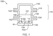
- FIG. 1 shows a chamber 100 for a bioreactor according to an embodiment of the invention.
- the chamber 100 has a body portion 110 having a cap module 140 and a body module 150.
- the cap module 140 and body module 150 are each provided with an inlet aperture 142, 152 and an outlet aperture 144, 154 respectively.
- the cap and body modules 140, 150 are arranged to couple together whereby a fluid-tight seal is formed between the modules.
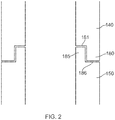
- FIG. 2 shows a configuration of the structure of the coupling between the cap and body modules 140, 150.
- rims 180, 185 of the cap and body modules 140, 150 respectively are provided with complementary formations.
- a rim 180 of the cap module 140 is provided with a recessed portion 181 along a radially inner circumferential edge of the rim 180 whilst a rim 185 of the body module 150 is provided with a recessed portion 186 along a radially outer circumferential edge.
- Skirt portions defied by respective remaining portions of rims 180, 185 are of a shape complementary to one another allowing coupling of the chambers together.
- the complementary formations are arranged to provide a friction fit.
- FIG. 3 shows a configuration of the structure of the coupling between the body module 150 of the chamber 100 and a basal portion 130. It can be seen that similar formations are provided to those allowing the cap and body modules 140, 150 to be coupled together.
- a rim 118 of the body module 150 is provided with a recess 117 of a shape corresponding to that of a recess 138 formed in a rim 137 of the basal portion 130.
- the basal portion 130 is formed from the same type of material as the cap and body modules 140, 150.
- the basal portion 130 is formed from a silicone rubber. Other materials are also useful.
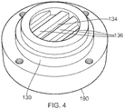
- FIG. 4 shows a perspective view of a basal portion 130 formed from silicone rubber.
- the basal portion 130 is shown mounted on a clamping plate 190.
- a corresponding clamping plate (not shown) is also provided that is arranged to be placed in abutment with the cap module 140 of the chamber 100. The two clamping plates are then clamped together in order to enhance a fluid-tightness of a seal between the modules. Clamping also enables the chamber 100 to withstand greater internal pressure without suffering undue deformation.
- the chamber 100 is configured to allow a first sample 101 in the form of a membrane 101 to be supported between the cap and body modules 140, 150 whereby a barrier to fluid flow between the cap and body modules 140, 150 may be formed.
- the membrane may be arranged to provide a molecularly selective filter.
- the membrane may allow diffusion or perfusion of molecules or other entities therethrough, including fluids or any required material.
- the membrane may in addition or instead provide a support for cells or other matter.
- the membrane 101 is supported by being trapped between rims 180, 185 of the cap and body modules 140, 150 when the cap and body modules 140, 150 respectively are coupled together.
- Other methods of supporting the membrane 101 between the cap and body modules 140, 150 are also useful.
- clamping of modules together using a clamping plate 190 or other mechanism can beneficially increase a force trapping the sample 101 between rims 180, 185.
- the body portion 110 and the basal portion 130 are formed from a resiliently flexible material such as a polymeric material.
- the portions 130, 110 are formed from a silicone material.
- the portions 130, 110 are formed from a transparent material whereby a sample within the chamber 100 may be subjected to irradiation with visible, infra-red and/or ultraviolet light through one or both of the portions 130, 110.
- the basal portion 130 of the chamber 100 has a sample support portion 134 having a plurality of spaced apart ridge elements 136.
- the ridge elements 136 are arranged to support a second sample 102 in such a manner that fluid within an internal cavity (or 'reservoir') 156 of the body module 150 of the chamber 100 is able to contact the second sample 102 on a face of the sample 102 that is towards the sample support portion 134 as well as an opposite face of the sample.
- This feature reduces a risk that a tissue sample will experience necrosis on the face that is towards the sample support portion 134. Furthermore, this feature also facilitates removal of a sample 102 placed on the support portion 134. If the sample 102 is placed in contact with a substantially flat surface the effects of surface tension can render the task of removing the sample 102 from the support portion 134 difficult. In such situations, samples such as thin membranes or glass cover-slips can otherwise become damaged during a process of removal.
- FIG. 4(a) Whilst the embodiment of FIG. 4(a) is provided with ridge elements, it is to be understood that in some other embodiments one or more post elements may be provided.
- FIG. 4(b) shows an embodiment in which post elements are provided in the form of rectangular cuboids 137 whilst
- FIG. 4(c) shows an embodiment in which post elements are provided in the form of domed elements 138. Other shapes are also useful.
- one or more domed formations may be provided.
- the chamber 100 is arranged to allow two separate fluid flowpaths to be established therethrough when a barrier such as a sample 101 in the form of a membrane is provided between the cap and body modules 140, 150.
- a first flowpath is arranged from the inlet aperture 142 to the outlet aperture 144 of the cap module 140.
- a second flowpath is arranged from the inlet aperture 152 to the outlet aperture 154 of the body module 150.
- a flow of fluid or other substances between the cap and body modules 140, 150 is constrained to occur by transport through the sample 101.
- locations and sizes of the inlet aperture 142 and outlet aperture 144 of the cap module 140 and/or the locations of the inlet aperture 152 and outlet aperture 154 of the body module in the embodiment of FIG. 1 may be arranged so as to minimise or at least reduce a deleterious effect of the fluid flow on samples 101 and/or 102, respectively.
- cell seeding or other phenomena may be arranged to occur on the second sample 102, the first sample 101 being a membrane arranged to allow perfusion of fluid and/or certain molecules or other entities therethrough. Limiting a deleterious effect of the flow of fluid through the body module 150 on the growth, function and/or viability of cellular or other material on the second sample 102 may be an important factor in establishing suitable conditions.
- the outlet aperture of a module is arranged to be of a larger diameter than the inlet aperture of the module. In some embodiments the outlet aperture is greater than the inlet aperture by a factor of around 1.5 or more. In some embodiments the outlet aperture is greater than the inlet aperture by a factor of around 2 or more.
- the present inventors have determined that the height H in of the inlet aperture 152 above the support portion 134 and the height H out of the outlet aperture 154 above the support portion 134 ( FIG. 1 ) are factors that influence the fluid flow conditions at the support portion 134.
- heights H in and H out may be arranged to provide an optimum balance between larger values of H in and H out in order to achieve a reduced amount of shear stress on an upper surface of the second sample 102, and smaller values of H in and H out in order to avoid an excessive amount of turbulent flow at the sample surface.
- the heights of the inlet and outlet apertures 142, 144 of the cap module 140 above the first sample 101 may also be selected so as to provide a balance between an amount of shear stress imposed on the sample 101 by flow of fluid through the cap module 140 and an extent to which flow of fluid through the cap module 140 occurs under laminar flow conditions.
- the heights may also be arranged to reduce or prevent depletion of oxygen or nutrients at the sample.
- FIG. 6 shows an embodiment of the invention in which a chamber 200 similar to that of FIG. 1 is provided, the chamber 200 having a cap module 210 that is substantially the same as that of the chamber 100 of FIG. 1 and first and second body modules 250, 260 each substantially identical to the body module 150 of the embodiment of FIG. 1 .
- first and second body modules 250, 260 are stacked on top of one another such that the body portion 210 has first, second and third internal cavities 216, 256, 266.
- the first and second internal cavities 216, 256 are arranged to be separated from one another by means of a first sample 201 whilst the second and third internal cavities 256, 266 are arranged to be separated from one another by means of a second sample 202.
- a third sample 203 may be provided on a support portion 234 provided by the basal portion 230.
- the first and second samples 201, 202 are membranes arranged to allow diffusion of required substances therethrough whilst the third sample 203 is a sample upon which cellular seeding is arranged to occur.
- a flow of fluid may be established independently through each of the first, second and third internal cavities 216, 256, 266 respectively.
- Respective inlet and outlet apertures 212, 214 (first cavity), 252, 254 (second cavity) and 262, 264 (third cavity) are provided to facilitate the flow of fluid through the respective cavities.
- the heights H in and H out of inlet aperture 262 and outlet aperture 264 of the third cavity 266 may be arranged to provide an optimum balance between an amount of shear stress imposed on an upper surface of the third sample 203 and an extent to which flow of fluid over the third sample 203 is turbulent.
- the heights may also be arranged to reduce or prevent depletion of oxygen or nutrients at the sample.
- the heights of the inlet and outlet apertures of the cap module 210 and first body module 250 above first and second samples 201, 202 may also be adjusted to provide an optimum balance between the amount of shear stress imposed on the samples 201, 202 due to fluid flow through the modules 210, 250 and an extent to which flow of fluid at the surface of the samples 201, 202 is turbulent.
- the heights may also be arranged to reduce or prevent depletion of oxygen or nutrients at the sample.
- a chamber 200 with substantially any number of body modules 250, 260 may be provided as required for any given application.
- body modules 250, 260 are substantially identical components.
- FIG. 7 shows an embodiment of the invention in which a basal module 370 is provided instead of a basal portion 130 ( FIG. 1 ).
- the basal module 370 may be considered to be a combination of a body module 150 and a basal portion 130 of the embodiment of FIG. 1 , the basal module 330 being provided in the form of a single module 370.
- a basal module 370 according to the embodiment of FIG. 7 has the advantage that a risk of fluid leaks from a seal formed between a body module 150 and a basal portion 130 of the embodiment of FIG. 1 is reduced.
- one or more body modules 150 may be coupled between the cap module 310 and basal module 370 of the embodiment of FIG. 7 .
- FIG. 8 shows a chamber 400 in which a cap module 411 and a basal module 471 are provided not having inlet apertures or outlet apertures.
- the cap module 411 is coupled to a body module 450 which is in turn coupled to the basal module 471 such that the body module 450 is sandwiched between the cap and basal modules 411, 471.
- the body module 450 is provided with inlet and outlet apertures 452, 454 arranged to allow passage of fluid through the module 450.
- a membrane 401 provides a barrier between an internal cavity 416 of the cap module 411 and an internal cavity 456 of the body module 450.
- a membrane 402 provides a barrier between the internal cavity 456 of the body module 450 and an internal cavity 476 of the basal module 471.
- a supply of fluid may be provided in the internal cavities 416, 476 of the cap and basal modules 411, 471.
- a chamber 400 according to the embodiment of FIG. 8 can allow simulation of biological tissue that is fed by surrounding capillaries.
- tissue samples may be provided in one or both of the cap and basal modules 411, 471 and a supply of fluid passed through the body module 450, the fluid passing through the body module 450 being arranged to simulate a flow of blood through capillaries associated with the biological tissue.
- the biological tissue may be provided on a sample support of one or both of the cap and basal modules 411, 471.
- the biological tissue may be provided on one or both of the membranes 401, 402, for example on a side facing into the cavity of a respective cap or basal module 411, 471.
- FIG. 9 (a) shows an embodiment in which chambers 500 according to embodiments of the invention are coupled together in series to form an assembly of chambers.
- a corresponding assembly of chambers 500 coupled in parallel is shown in FIG. 9(b) .
- FIG. 9(c) shows an assembly of chambers in which a first chamber 600A has a basal module 671 having no inlet or outlet aperture, the basal module 671 being coupled to a cap module 610 having an inlet aperture and an outlet aperture 612, 614.
- a membrane 601A is provided between the cap module and the basal module of the first chamber 600A.
- the cap module of the first chamber 600A is coupled to a cap module 610 of a second chamber 600B, the cap module of the second chamber 600B being similar to that of the first chamber 600A in that it is also provided with an inlet aperture 612 and an outlet aperture 614.
- the cap module 610 of the second chamber 600B is coupled to a basal module 670 of the second chamber also having an inlet aperture 672 and an outlet aperture 674.
- a sample 601B in the form of a membrane is provided between the cap module 610 and the basal module 670.
- a further sample may be provided on a sample support of the basal module 670 of the second chamber, the basal module 671 of the first chamber, or any other module of the first or second chambers 600A, 600B.
- bioreactor may be formed suitable for the simulation of highly complex biological processes.
- Embodiments of the present invention provide a highly effective way of providing such bioreactors, allowing a user a very high degree of flexibility in choice of reactor configuration and an ability to make modifications and adjustments in a rapid and efficient manner.
- the cap, body and basal modules and the basal portion are arranged to couple to one another at least in part by means of a friction fit, allowing releasable coupling to one another in a convenient manner not requiring special tools.
- the modules and portion are formed from a silicone rubber material, being a resiliently deformable material having a self-adhesive property. This promotes the formation of a substantially water-tight joint between modules and/or between a module and the basal portion.
- the silicone rubber is formed to be substantially transparent to light, allowing exposure of cells within a chamber 100, 200, 300 to be exposed to light to test an influence of visible (or infra-red) light on cell function.
- one or more modules and the basal portion may be formed by moulding. Other methods of forming the modules and basal portion are also useful.
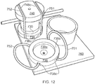
- FIG. 10(a) shows a pair of clamp members 738, 748 arranged to sandwich a basal portion 730 and a body portion 710 of a chamber 700 therebetween.
- FIG. 10(a) shows two chambers 700 so arranged. It is to be understood that in some assemblies only one chamber 700 is provided.
- FIG. 10(a) also shows the two chambers 700 in a configuration in which one clamp member 738 is provided on a substrate 760. In some assemblies the clamp member 738 is coupled to the substrate 760. In some assemblies no substrate 760 is provided.
- FIG. 10(b) is a cross-sectional view of one of the chambers 700 shown in the arrangement of FIG. 10(a) .
- the clamp members 738, 748 are substantially identical. As can be seen from FIG. 10 and FIG. 11 the clamp members 738, 748 are in the form of disc-like members each having a side having a recessed well portion 739a and a corresponding rim portion 739b ( FIG. 11(b) ). The well portion 739a of one clamp member 738 is sized to receive a portion of the basal portion 730 of the chamber therein.
- the other clamp member 748 has a corresponding recessed well portion arranged to receive a portion of the body portion 710 therein.
- the chamber 700 is arranged to be locatable between the clamp members 738, 748 whereby lateral movement of the clamp members with respect to the chamber 700 is constrained by the presence of the rim portions 739b.
- a pair of resilient elements are provided in the form of endless loops 751, 752.
- the clamp members 738, 748 are provided with recessed channels 738c on an outer major surface thereof (being the surface opposite the surface in which the well portion 739a is provided).
- the recessed channels 738c are substantially parallel to one another and are provided at locations disposed equal distances D' from a longitudinal axis L of the disc element 738, 748 but on opposite sides of the axis L.
- distance D' is a radial distance of the closest point of channel 738c to the axis L.
- distance D' is around two thirds of a radius of the clamp member 738. Other distances are also useful.
- a lower clamp member 738 is coupled to a substrate 760 trapping the loops 751, 752 to lie within their respective channel 738c.
- the lower clamp member 738 may be coupled to the substrate 760 by permanent fixing means such as an adhesive or by means of releasable fixing means.
- the releasable fixing means may be a mechanical fixing element such as a screw or bolt, hook and loop fixing means (e.g. Velcro(R)), a releasable adhesive or any other suitable releasable fixing means.
- a clamp member 748 (an upper clamp member) is positioned over the chamber with channels 748c of the upper clamp member 748 substantially parallel to those of the lower clamp member 738.
- the endless loops 751, 752 are sized such that they can be positioned so as to lie in respective channels 748c of the upper clamp member 748.
- the endless loops are arranged to exert a sufficient force to clamp the body portion 710 and basal portion 730 of the chamber 700 together to prevent leakage of fluid from the chamber through a joint between the body and basal portions 710, 730.
- Assemblies such as those of FIGs 10 to 13 have the advantage that a substantially equal clamping force may be applied by respective resilient elements 751, 752 at substantially equal distances either side of the longitudinal axis L of the chamber 700.
- clamping forces applied to the chamber 700 are balanced and a stable clamping arrangement may be provided.
- a chamber 700 clamped between clamp members 738, 748 is subject to substantially uniform pressure by the clamp members 738, 748. This has the advantage that a seal between the body portion 710 and basal portion 730 is also subject to uniform pressure by the clamp members 738, 748 reducing a risk of leakage of fluid.
- resilient elements other than endless loops are provided.
- the resilient elements are in the form of resiliently extensible linear elements.
- the linear elements may be flexible elements, such as lengths of an elastomer.
- the linear elements may be provided with one or more hook elements to facilitate coupling of the linear elements to a clamp member.
- the lower and upper clamp members 738, 748 may be formed integrally with basal and body portions of the chamber. Alternatively, the lower and upper clamp members 738, 748 may be permanently coupled to basal and body portions of the chamber. In some assemblies the lower and upper clamp members 738, 748 are releasably coupled to basal and body portions of the chamber.
Landscapes
- Health & Medical Sciences (AREA)
- Chemical & Material Sciences (AREA)
- Organic Chemistry (AREA)
- Zoology (AREA)
- Wood Science & Technology (AREA)
- Life Sciences & Earth Sciences (AREA)
- Engineering & Computer Science (AREA)
- Bioinformatics & Cheminformatics (AREA)
- Microbiology (AREA)
- Biotechnology (AREA)
- Biomedical Technology (AREA)
- Sustainable Development (AREA)
- Biochemistry (AREA)
- General Engineering & Computer Science (AREA)
- General Health & Medical Sciences (AREA)
- Genetics & Genomics (AREA)
- Clinical Laboratory Science (AREA)
- Chemical Kinetics & Catalysis (AREA)
- Immunology (AREA)
- Apparatus Associated With Microorganisms And Enzymes (AREA)
Description
- The present invention relates to chambers for bioreactors.
- It is known to provide a bioreactor having a culture chamber and means for passing a flow of culture medium through the chamber in order to enable a wide range of studies of biological materials. By way of example, the biological material under investigation may be a monolayer cell culture, scaffold culture or tissue slice.
WO2005/123258 discloses a bioreactor for studying the effects of imposed stimuli on cellular activity.WO2007021919A1 is concerned with a bioreactor system comprising a gasket to form a seal between modules. - In a first aspect of the invention there is provided a bioreactor chamber assembly comprising:
- a chamber comprising a plurality of modules arranged to be coupled together to form the chamber,
- wherein respective modules are provided with one or more respective complementary formations arranged whereby the modules are configured to be coupled to one another, the complementary formations comprising a resiliently deformable material and configured to form a liquid-tight seal between the respective formations without a requirement for a separate seal element
- characterised by
- one or more membranes provided between at least two of the plurality of modules and within the chamber, to partition the chamber into a plurality of fluid reservoirs, and
- at least one module of the chamber having a fluid inlet aperture and a fluid outlet aperture, and arranged for establishing fluid flow through a reservoir.
- This has the advantage that because a separate seal element (such as an 'O' ring or any other seal element) is not required, assembly of a module may be made in a more rapid and convenient manner. Furthermore, a component count of a chamber may be reduced thereby simplifying manufacture and assembly.
- In addition, a compatibility of a seal element with liquid or other fluid in a chamber does not need to be verified. Thus, a usefulness of the chamber may be enhanced. A possibility of contamination of a content of a chamber due to an influence of a seal element is thereby eliminated.
- Each reservoir may be associated with a different respective module.
- Preferably the membrane is provided at a location substantially between a pair of adjacent modules.
- The assembly may be arranged wherein the membrane is provided in the form of a substantially flat sheet of material.
- Preferably the membrane is arranged to allow passage of a prescribed substance therethrough.
- Preferably the membrane is arranged to allow passage of a prescribed substance therethrough wherein the substance is selected from amongst a fluid; a chemical compound, moiety or element; an ion; and a biological material.
- The assembly may be arranged wherein the fluid inlet aperture of the at least one module is arranged such that fluid entering a reservoir of the chamber through the inlet aperture flows in a direction substantially parallel to a plane of a membrane defining a boundary of the reservoir.
- Preferably the modules have substantially the same cross-sectional area as one another.
- Preferably the modules may be releasably coupled to one another.
- Preferably the one or more formations of a first module comprise a rim of an end of a wall of the first module, the rim having a recess formed in a radially inner circumferential portion of the rim whereby the remaining portion of the rim defines a substantially circumferential skirt portion.
- Preferably a corresponding one or more formations of a second module comprise a corresponding portion of a rim of an end of a wall of said second module, the wall having a recess formed in a radially outer circumferential portion whereby the remaining portion of the wall defines a skirt portion having a shape and size complementary to that of the skirt portion of the first module.
- The first and second modules may be arranged to allow a membrane to be coupled between them by entrapment of a portion of the membrane between respective adjacent rims of the first and second modules.
- Preferably the assembly is arranged whereby entrapment of a membrane may be effected when adjacent modules are coupled to one another.
- Preferably the fluid inlet aperture and fluid outlet aperture of the at least one module are provided at substantially opposite locations of the wall of the chamber.
- Preferably the chamber is substantially cylindrical in shape.
- Preferably each module is substantially cylindrical in shape, the modules being arranged in a substantially coaxial configuration.
- Preferably the inlet aperture and the outlet aperture are provided at diametrically opposite locations of each module.
- Preferably the assembly comprises a module not having a fluid inlet aperture or a fluid outlet aperture.
- Preferably the assembly is further provided with a sample support arranged to support a sample in the form of a membrane, the support being arranged to allow each of a pair of opposed major faces of the membrane to be exposed to fluid contained within the chamber.
- Preferably the sample support comprises at least one support member arranged to contact a portion of the sample.
- Preferably the at least one support member comprises a ridged element, the ridged element being elongate in a substantially lateral direction thereby to provide an elongate surface upon which a sample may be placed.
- Preferably the at least one support member comprises at least one post element.
- Preferably the at least one post element is provided with an upper surface arranged to contact a sample, the upper surface being one selected from amongst substantially flat, substantially curved and substantially domed.
- Preferably the at least one support member comprises an element substantially in the form of a hemisphere or portion thereof.
- Preferably the sample support comprises a plurality of support members each support member being arranged to contact a portion of the sample.
- Preferably the plurality of support members are substantially parallel to one another.
- The support members may be of substantially square or rectangular cross-section.
- Preferably a cap module is provided comprising a module arranged to define a closed end of the chamber.
- Preferably the cap module has a hollow, cupped body portion.
- The cap module may be arranged to receive a sample therein.
- Preferably the sample support is provided in the cap module.
- A further cap module may be provided at an opposite end of the chamber to said cap module.
- Preferably the modules are arranged to couple to one another at least in part by means of a friction fit.
- Preferably the complementary formations are formed from a material having a self-adhesive property.
- Respective complementary formations may be arranged to form a bond with one another.
- The bond may be a releasable bond.
- Alternatively, the bond may be a substantially permanent bond.
- The complementary formations and a remainder of the modules may be formed from substantially the same material.
- Preferably the one or more respective complementary formations of a module are integrally formed with the module.
- The complementary formations may be formed from a silicone material.
- Preferably at least one module comprises a substantially transparent or translucent material thereby to allow light to irradiate a sample provided within the chamber.
- Preferably the one or more membranes may be molecularly selective filters.
- In a second aspect of the invention there is provided bioreactor apparatus comprising a plurality of bioreactor chamber assemblies according to the first aspect wherein a first reservoir of a first chamber assembly is coupled to a first reservoir of a second chamber assembly.
- The first reservoirs of the first and second chambers may be coupled in series for fluid to flow through the first reservoir of the first chamber and subsequently through the first reservoir of the second chamber.
- Alternatively, the first reservoirs of the first and second chambers may be coupled in parallel.
- Embodiments of the invention will now be described with reference to the accompanying figures in which:
-
FIGURE 1 is a cross-sectional view of a chamber suitable for use in dual-cavity (or 'dual-reservoir') perfusion experiments; -
FIGURE 2 is a cross-sectional view of rim portions of adjacent modules of the chamber ofFIG. 1 showing complementary formations by means of which the modules may be coupled together; -
FIGURE 3 is a cross-sectional view of a configuration of a coupling between a basal portion of the chamber and a body module; -
FIGURE 4 is a perspective view of a basal portion also showing a lower clamping plate; -
FIGURE 5 is a cross-sectional view of rim portions of adjacent modules showing how a membrane may be gripped between adjacent modules; -
FIGURE 6 is a cross-sectional view of a chamber suitable for use in triple-cavity perfusion experiments; -
FIGURE 7 is a cross-sectional view of a chamber according to a further embodiment of the invention; -
FIGURE 8 shows a chamber according to an embodiment of the invention; and -
FIGURE 9 (a) to (c) show assemblies of chambers according to embodiments of the invention; -
FIGURE 10 shows a chamber assembly in which a chamber is sandwiched between two clamp members in (a) perspective view and (b) cross-sectional view; -
FIGURE 11 shows (a) an outer surface and (b) an inner surface of a clamp member of a chamber assembly; -
FIGURE 12 is a perspective view of a substrate having a pair of clamp members fixedly coupled thereto to which respective chambers may be attached; -
FIGURE 13 is a plan view of the substrate ofFIG. 12 ; and - FIGURE 14 shows a chamber assembly having a body portion and a basal portion clamped between clamp members.
-
FIG. 1 shows achamber 100 for a bioreactor according to an embodiment of the invention. Thechamber 100 has abody portion 110 having acap module 140 and abody module 150. Thecap module 140 andbody module 150 are each provided with aninlet aperture outlet aperture - The cap and
body modules -
FIG. 2 shows a configuration of the structure of the coupling between the cap andbody modules body modules rim 180 of thecap module 140 is provided with a recessedportion 181 along a radially inner circumferential edge of therim 180 whilst arim 185 of thebody module 150 is provided with a recessedportion 186 along a radially outer circumferential edge. Skirt portions defied by respective remaining portions ofrims - In some embodiments the complementary formations are arranged to provide a friction fit.
-
FIG. 3 shows a configuration of the structure of the coupling between thebody module 150 of thechamber 100 and abasal portion 130. It can be seen that similar formations are provided to those allowing the cap andbody modules rim 118 of thebody module 150 is provided with arecess 117 of a shape corresponding to that of arecess 138 formed in arim 137 of thebasal portion 130. - In some embodiments the
basal portion 130 is formed from the same type of material as the cap andbody modules basal portion 130 is formed from a silicone rubber. Other materials are also useful. -
FIG. 4 shows a perspective view of abasal portion 130 formed from silicone rubber. Thebasal portion 130 is shown mounted on aclamping plate 190. A corresponding clamping plate (not shown) is also provided that is arranged to be placed in abutment with thecap module 140 of thechamber 100. The two clamping plates are then clamped together in order to enhance a fluid-tightness of a seal between the modules. Clamping also enables thechamber 100 to withstand greater internal pressure without suffering undue deformation. - As illustrated in
FIG. 5 , thechamber 100 is configured to allow afirst sample 101 in the form of amembrane 101 to be supported between the cap andbody modules body modules - In the arrangement of
FIG. 5 themembrane 101 is supported by being trapped betweenrims body modules body modules membrane 101 between the cap andbody modules - It will be understood that clamping of modules together using a
clamping plate 190 or other mechanism can beneficially increase a force trapping thesample 101 betweenrims - In some embodiments of the invention the
body portion 110 and thebasal portion 130 are formed from a resiliently flexible material such as a polymeric material. In some embodiments theportions portions chamber 100 may be subjected to irradiation with visible, infra-red and/or ultraviolet light through one or both of theportions - As can be seen in
FIG. 4 thebasal portion 130 of thechamber 100 has asample support portion 134 having a plurality of spaced apartridge elements 136. Theridge elements 136 are arranged to support a second sample 102 in such a manner that fluid within an internal cavity (or 'reservoir') 156 of thebody module 150 of thechamber 100 is able to contact the second sample 102 on a face of the sample 102 that is towards thesample support portion 134 as well as an opposite face of the sample. - This feature reduces a risk that a tissue sample will experience necrosis on the face that is towards the
sample support portion 134. Furthermore, this feature also facilitates removal of a sample 102 placed on thesupport portion 134. If the sample 102 is placed in contact with a substantially flat surface the effects of surface tension can render the task of removing the sample 102 from thesupport portion 134 difficult. In such situations, samples such as thin membranes or glass cover-slips can otherwise become damaged during a process of removal. - It is to be understood that other means for supporting a sample may be provided, such as a plurality of polygonal protrusions such as triangular, square or rectangular protrusions, or circular, spherical protrusions or protrusions of any other suitable shape.
- Whilst the embodiment of
FIG. 4(a) is provided with ridge elements, it is to be understood that in some other embodiments one or more post elements may be provided.FIG. 4(b) shows an embodiment in which post elements are provided in the form ofrectangular cuboids 137 whilstFIG. 4(c) shows an embodiment in which post elements are provided in the form ofdomed elements 138. Other shapes are also useful. In some embodiments one or more domed formations may be provided. - The
chamber 100 is arranged to allow two separate fluid flowpaths to be established therethrough when a barrier such as asample 101 in the form of a membrane is provided between the cap andbody modules inlet aperture 142 to theoutlet aperture 144 of thecap module 140. A second flowpath is arranged from theinlet aperture 152 to theoutlet aperture 154 of thebody module 150. - In some embodiments, a flow of fluid or other substances between the cap and
body modules sample 101. - It is to be understood that locations and sizes of the
inlet aperture 142 andoutlet aperture 144 of thecap module 140 and/or the locations of theinlet aperture 152 andoutlet aperture 154 of the body module in the embodiment ofFIG. 1 may be arranged so as to minimise or at least reduce a deleterious effect of the fluid flow onsamples 101 and/or 102, respectively. - For example, in some embodiments cell seeding or other phenomena may be arranged to occur on the second sample 102, the
first sample 101 being a membrane arranged to allow perfusion of fluid and/or certain molecules or other entities therethrough. Limiting a deleterious effect of the flow of fluid through thebody module 150 on the growth, function and/or viability of cellular or other material on the second sample 102 may be an important factor in establishing suitable conditions. - In some embodiments the outlet aperture of a module is arranged to be of a larger diameter than the inlet aperture of the module. In some embodiments the outlet aperture is greater than the inlet aperture by a factor of around 1.5 or more. In some embodiments the outlet aperture is greater than the inlet aperture by a factor of around 2 or more.
- The present inventors have determined that the height Hin of the
inlet aperture 152 above thesupport portion 134 and the height Hout of theoutlet aperture 154 above the support portion 134 (FIG. 1 ) are factors that influence the fluid flow conditions at thesupport portion 134. - The inventors have recognised that heights Hin and Hout may be arranged to provide an optimum balance between larger values of Hin and Hout in order to achieve a reduced amount of shear stress on an upper surface of the second sample 102, and smaller values of Hin and Hout in order to avoid an excessive amount of turbulent flow at the sample surface. The heights of the inlet and
outlet apertures cap module 140 above thefirst sample 101 may also be selected so as to provide a balance between an amount of shear stress imposed on thesample 101 by flow of fluid through thecap module 140 and an extent to which flow of fluid through thecap module 140 occurs under laminar flow conditions. The heights may also be arranged to reduce or prevent depletion of oxygen or nutrients at the sample. -
FIG. 6 shows an embodiment of the invention in which achamber 200 similar to that ofFIG. 1 is provided, thechamber 200 having acap module 210 that is substantially the same as that of thechamber 100 ofFIG. 1 and first andsecond body modules 250, 260 each substantially identical to thebody module 150 of the embodiment ofFIG. 1 . - In the embodiment of
FIG. 6 the first andsecond body modules 250, 260 are stacked on top of one another such that thebody portion 210 has first, second and thirdinternal cavities - The first and second
internal cavities first sample 201 whilst the second and thirdinternal cavities second sample 202. Athird sample 203 may be provided on asupport portion 234 provided by thebasal portion 230. - In some embodiments the first and
second samples third sample 203 is a sample upon which cellular seeding is arranged to occur. - A flow of fluid may be established independently through each of the first, second and third
internal cavities outlet apertures 212, 214 (first cavity), 252, 254 (second cavity) and 262, 264 (third cavity) are provided to facilitate the flow of fluid through the respective cavities. - For the reasons discussed above in relation to the embodiment of
FIG. 1 , the heights Hin and Hout ofinlet aperture 262 andoutlet aperture 264 of thethird cavity 266 may be arranged to provide an optimum balance between an amount of shear stress imposed on an upper surface of thethird sample 203 and an extent to which flow of fluid over thethird sample 203 is turbulent. The heights may also be arranged to reduce or prevent depletion of oxygen or nutrients at the sample. - Similarly, the heights of the inlet and outlet apertures of the
cap module 210 and first body module 250 above first andsecond samples samples modules 210, 250 and an extent to which flow of fluid at the surface of thesamples - It is to be understood that due to the modular nature of the
chamber 200, achamber 200 with substantially any number ofbody modules 250, 260 may be provided as required for any given application. In someembodiments body modules 250, 260 are substantially identical components. -
FIG. 7 shows an embodiment of the invention in which abasal module 370 is provided instead of a basal portion 130 (FIG. 1 ). In the embodiment ofFIG. 7 thebasal module 370 may be considered to be a combination of abody module 150 and abasal portion 130 of the embodiment ofFIG. 1 , the basal module 330 being provided in the form of asingle module 370. Abasal module 370 according to the embodiment ofFIG. 7 has the advantage that a risk of fluid leaks from a seal formed between abody module 150 and abasal portion 130 of the embodiment ofFIG. 1 is reduced. - It is to be understood that in some variations of the embodiment of
FIG. 7 one ormore body modules 150 may be coupled between thecap module 310 andbasal module 370 of the embodiment ofFIG. 7 . -
FIG. 8 shows achamber 400 in which acap module 411 and abasal module 471 are provided not having inlet apertures or outlet apertures. Thecap module 411 is coupled to abody module 450 which is in turn coupled to thebasal module 471 such that thebody module 450 is sandwiched between the cap andbasal modules body module 450 is provided with inlet andoutlet apertures module 450. - A
membrane 401 provides a barrier between aninternal cavity 416 of thecap module 411 and aninternal cavity 456 of thebody module 450. Amembrane 402 provides a barrier between theinternal cavity 456 of thebody module 450 and aninternal cavity 476 of thebasal module 471. - In the embodiment of
FIG. 8 a supply of fluid may be provided in theinternal cavities basal modules chamber 400 according to the embodiment ofFIG. 8 can allow simulation of biological tissue that is fed by surrounding capillaries. Thus, for example tissue samples may be provided in one or both of the cap andbasal modules body module 450, the fluid passing through thebody module 450 being arranged to simulate a flow of blood through capillaries associated with the biological tissue. The biological tissue may be provided on a sample support of one or both of the cap andbasal modules membranes basal module -
FIG. 9 (a) shows an embodiment in whichchambers 500 according to embodiments of the invention are coupled together in series to form an assembly of chambers. A corresponding assembly ofchambers 500 coupled in parallel is shown inFIG. 9(b) . -
FIG. 9(c) shows an assembly of chambers in which afirst chamber 600A has abasal module 671 having no inlet or outlet aperture, thebasal module 671 being coupled to acap module 610 having an inlet aperture and anoutlet aperture membrane 601A is provided between the cap module and the basal module of thefirst chamber 600A. - The cap module of the
first chamber 600A is coupled to acap module 610 of asecond chamber 600B, the cap module of thesecond chamber 600B being similar to that of thefirst chamber 600A in that it is also provided with aninlet aperture 612 and anoutlet aperture 614. - The
cap module 610 of thesecond chamber 600B is coupled to abasal module 670 of the second chamber also having aninlet aperture 672 and anoutlet aperture 674. A sample 601B in the form of a membrane is provided between thecap module 610 and thebasal module 670. A further sample may be provided on a sample support of thebasal module 670 of the second chamber, thebasal module 671 of the first chamber, or any other module of the first orsecond chambers - It is to be understood that by suitable choice of chamber configuration by assembly of modules of different respective types a bioreactor may be formed suitable for the simulation of highly complex biological processes.
- Embodiments of the present invention provide a highly effective way of providing such bioreactors, allowing a user a very high degree of flexibility in choice of reactor configuration and an ability to make modifications and adjustments in a rapid and efficient manner.
- In the embodiment shown in the figures the cap, body and basal modules and the basal portion are arranged to couple to one another at least in part by means of a friction fit, allowing releasable coupling to one another in a convenient manner not requiring special tools. The modules and portion are formed from a silicone rubber material, being a resiliently deformable material having a self-adhesive property. This promotes the formation of a substantially water-tight joint between modules and/or between a module and the basal portion.
- In the embodiment shown the silicone rubber is formed to be substantially transparent to light, allowing exposure of cells within a
chamber - It is to be understood that other materials and forms of material are also useful for forming the modules and basal portion.
- It will be apparent to persons skilled in the art that one or more modules and the basal portion may be formed by moulding. Other methods of forming the modules and basal portion are also useful.
-
FIG. 10(a) shows a pair ofclamp members basal portion 730 and abody portion 710 of achamber 700 therebetween.FIG. 10(a) shows twochambers 700 so arranged. It is to be understood that in some assemblies only onechamber 700 is provided.FIG. 10(a) also shows the twochambers 700 in a configuration in which oneclamp member 738 is provided on asubstrate 760. In some assemblies theclamp member 738 is coupled to thesubstrate 760. In some assemblies nosubstrate 760 is provided. -
FIG. 10(b) is a cross-sectional view of one of thechambers 700 shown in the arrangement ofFIG. 10(a) . - In some assemblies the
clamp members FIG. 10 andFIG. 11 theclamp members well portion 739a and acorresponding rim portion 739b (FIG. 11(b) ). Thewell portion 739a of oneclamp member 738 is sized to receive a portion of thebasal portion 730 of the chamber therein. - The
other clamp member 748 has a corresponding recessed well portion arranged to receive a portion of thebody portion 710 therein. - Thus, in some assemblies the
chamber 700 is arranged to be locatable between theclamp members chamber 700 is constrained by the presence of therim portions 739b. - In order to provide a clamping force between the
clamp members FIGs. 10 to 13 a pair of resilient elements are provided in the form ofendless loops clamp members channels 738c on an outer major surface thereof (being the surface opposite the surface in which thewell portion 739a is provided). In the assembly shown the recessedchannels 738c are substantially parallel to one another and are provided at locations disposed equal distances D' from a longitudinal axis L of thedisc element channel 738c to the axis L. In some assemblies where theclamp member 738 is a disc-like member distance D' is around two thirds of a radius of theclamp member 738. Other distances are also useful. - In the assemblies of
FIGs. 12 and13 alower clamp member 738 is coupled to asubstrate 760 trapping theloops respective channel 738c. Thelower clamp member 738 may be coupled to thesubstrate 760 by permanent fixing means such as an adhesive or by means of releasable fixing means. The releasable fixing means may be a mechanical fixing element such as a screw or bolt, hook and loop fixing means (e.g. Velcro(R)), a releasable adhesive or any other suitable releasable fixing means. - It can be seen from
FIG. 12 that a clamp member 748 (an upper clamp member) is positioned over the chamber withchannels 748c of theupper clamp member 748 substantially parallel to those of thelower clamp member 738. Theendless loops respective channels 748c of theupper clamp member 748. The endless loops are arranged to exert a sufficient force to clamp thebody portion 710 andbasal portion 730 of thechamber 700 together to prevent leakage of fluid from the chamber through a joint between the body andbasal portions - Assemblies such as those of
FIGs 10 to 13 have the advantage that a substantially equal clamping force may be applied by respectiveresilient elements chamber 700. Thus, clamping forces applied to thechamber 700 are balanced and a stable clamping arrangement may be provided. - It is to be understood that this has the effect that a torque applied to a clamping
member resilient element resilient element respective clamp members - Furthermore, a
chamber 700 clamped betweenclamp members clamp members body portion 710 andbasal portion 730 is also subject to uniform pressure by theclamp members - In some assemblies, resilient elements other than endless loops are provided. In some assemblies the resilient elements are in the form of resiliently extensible linear elements. The linear elements may be flexible elements, such as lengths of an elastomer. The linear elements may be provided with one or more hook elements to facilitate coupling of the linear elements to a clamp member.
- It is to be understood that in some assemblies the lower and
upper clamp members upper clamp members upper clamp members - Throughout the description and claims of this specification, the words "comprise" and "contain" and variations of the words, for example "comprising" and "comprises", means "including but not limited to", and is not intended to (and does not) exclude other moieties, additives, components, integers or steps.
- Throughout the description and claims of this specification, the singular encompasses the plural unless the context otherwise requires. In particular, where the indefinite article is used, the specification is to be understood as contemplating plurality as well as singularity, unless the context requires otherwise.
Claims (16)
- A bioreactor chamber assembly comprising:a chamber (100,200,300,400,500,600) comprising a plurality of modules (130,140,150;210,230,250,260;310,370;411,471;610,670,671) arranged to be coupled together to form the chamber (100,200,300,400,500,600),wherein respective modules (130,140,150;210,230,250,260;310,370;411,471;610,670,671) are provided with one or more respective complementary formations (180,181,185,186;117,118,137,138) arranged whereby the modules (130,140,150;210,230,250,260;310,370;411,471;610,670,671) are configured to be coupled to one another, the complementary formations (180,181,185,186;117,118,137,138) comprising a resiliently deformable material and configured to form a liquid-tight seal between the respective formations (180,181,185,186;117,118,137,138) without a requirement for a separate seal elementcharacterised byone or more membranes (101,201,202,401,402,601) provided between at least two of the plurality of modules (130,140,150;210,230,250,260;310,370;411,471;610, 670,671) and within the chamber (100,200,300,400,500,600), to partition the chamber (100,200,300,400,500,600) into a plurality of fluid reservoirs (216,256,266;416,456,476), andat least one module (140,150,210,260,310,370,450,610,670) of the chamber (100,200,300,400,500,600) having a fluid inlet aperture (142,152,212,252,262,452,612) and a fluid outlet aperture (144,154,214,254,264,454,614), and arranged for establishing fluid flow through a reservoir (216,256,266;416,456,476).
- An assembly as claimed in claim 1 arranged wherein the fluid inlet aperture (142,152,212,252,262,452,612) of the at least one module (130,140,150;210,230,250,260;310,370;411,471;610,670,671) is arranged such that fluid entering a reservoir (216,256,266;416,456,476) of the chamber (100,200,300,400,500,600) through the inlet aperture (142,152,212,252,262,452,612) flows in a direction substantially parallel to a plane of a membrane (101,201,202,401,402,601) defining a boundary of the reservoir (216,256,266;416,456,476).
- An assembly as claimed in claim 1 or 2 wherein the one or more formations of a first module (140,150,130) comprise a rim (180,185,118,137) of an end of a wall of the first module (140,150,130), the rim (180,185,118,137) having a recess (181,186,117,138) formed in a radially inner circumferential portion of the rim (180,185,118,137) whereby the remaining portion of the rim (180,185,118,137) defines a substantially circumferential skirt portion.
- An assembly as claimed in any one of claims 1, 2 or 3 wherein the fluid inlet aperture (142,152,212,252,262,452,612) and fluid outlet aperture (144,154,214,254,264,454,614) of the at least one module (140,150,210,260,310,370,450,610,670) are provided at substantially opposite locations of the wall of the chamber (100,200,300,400,500,600).
- An assembly as claimed in any preceding claim wherein the chamber (100,200,300,400,500,600) is substantially cylindrical in shape, and wherein each module (130,140,150;210,230,250,260;310,370;411,471;610,670,671) is substantially cylindrical in shape, the modules (130,140,150;210,230,250,260;310,370;411,471;610,670,671) being arranged in a substantially coaxial configuration.
- An assembly as claimed in any preceding claim further provided with a sample support arranged to support a sample in the form of a membrane (101,102;201,202,203;401,402;601), the support being arranged to allow each of a pair of opposed major faces of the membrane (101,102;201,202,203;401,402;601) to be exposed to fluid contained within the chamber (100,200,300,400,500,600).
- An assembly as claimed in claim 6 wherein the sample support comprises at least one support member (134,136,234) arranged to contact a portion of the sample.
- An assembly as claimed in any preceding claim wherein a cap module (140,210,310,411,610) is provided comprising a module arranged to define a closed end of the chamber (100,200,300,400,500,600).
- An assembly as claimed in claim 8 wherein the sample support (101,201,401,601) is provided in the cap module (140,210,310,411,610).
- An assembly as claimed in any preceding claim wherein the modules (130,140,150;210,230,250,260;310,370;411,471;610,670,671) are arranged to couple to one another at least in part by means of a friction fit.
- An assembly as claimed in any preceding claim wherein the complementary formations (180,181,185,186;117,118,137,138) are formed from a material having a self-adhesive property.
- An assembly as claimed in any preceding claim wherein the complementary formations (180,181,185,186;117,118,137,138) and a remainder of the modules (130,140,150;210,230,250,260;310,370;411,471;610,670,671) are formed from substantially the same material.
- An assembly as claimed in any preceding claim wherein the complementary formations (180,181,185,186;117,118,137,138) are formed from a silicone material.
- An assembly as claimed in any preceding claim wherein the one or more membranes (101,201,202,401,402,601) are molecularly selective filters.
- Bioreactor apparatus comprising a plurality of bioreactor chamber assemblies as claimed in any preceding claim wherein a first reservoir (216,256,266;416,456,476) of a first chamber assembly (100,200,300,400,500,600) is coupled to a first reservoir (216,256,266;416,456,476) of a second chamber assembly (100,200,300,400,500,600).
- Apparatus as claimed in claim 15 wherein the first reservoirs (216,256,266;416,456,476) of the first and second chambers (100,200,300,400,500,600) are coupled in series for fluid to flow through the first reservoir (216,256,266;416,456,476) of the first chamber (100,200,300,400,500,600) and subsequently through the first reservoir (216,256,266;416,456,476) of the second chamber (100,200,300,400,500,600).
Applications Claiming Priority (5)
| Application Number | Priority Date | Filing Date | Title |
|---|---|---|---|
| GB0814033A GB0814033D0 (en) | 2008-08-01 | 2008-08-01 | Multi-cavity bioreactor chamber |
| GB0814034A GB0814034D0 (en) | 2008-08-01 | 2008-08-01 | Improved bioreactor chamber |
| GB0908404A GB2470227A (en) | 2009-05-15 | 2009-05-15 | Multi-cavity bioreactor chamber |
| GB0908400A GB0908400D0 (en) | 2009-05-15 | 2009-05-15 | Improved bioreactor chamber |
| EP09785436.8 | 2009-07-31 |
Related Parent Applications (2)
| Application Number | Title | Priority Date | Filing Date |
|---|---|---|---|
| EP09785436.8 Division | 2009-07-31 | ||
| EP09785436.8 Division | 2008-08-01 | 2009-07-31 |
Publications (3)
| Publication Number | Publication Date |
|---|---|
| EP2319912A1 EP2319912A1 (en) | 2011-05-11 |
| EP2319912B1 true EP2319912B1 (en) | 2019-01-02 |
| EP2319912B8 EP2319912B8 (en) | 2019-03-13 |
Family
ID=41610789
Family Applications (2)
| Application Number | Title | Priority Date | Filing Date |
|---|---|---|---|
| EP09785437.6A Active EP2318510B1 (en) | 2008-08-01 | 2009-07-31 | Improved bioreactor chamber |
| EP11156298.9A Active EP2319912B8 (en) | 2008-08-01 | 2009-07-31 | Bioreactor Chamber |
Family Applications Before (1)
| Application Number | Title | Priority Date | Filing Date |
|---|---|---|---|
| EP09785437.6A Active EP2318510B1 (en) | 2008-08-01 | 2009-07-31 | Improved bioreactor chamber |
Country Status (3)
| Country | Link |
|---|---|
| US (2) | US8735144B2 (en) |
| EP (2) | EP2318510B1 (en) |
| WO (2) | WO2010013069A2 (en) |
Families Citing this family (10)
| Publication number | Priority date | Publication date | Assignee | Title |
|---|---|---|---|---|
| GB201108165D0 (en) | 2011-05-16 | 2011-06-29 | Kirkstall Ltd | Bioreactor chamber and method |
| WO2012156682A1 (en) | 2011-05-16 | 2012-11-22 | Parker Hannifin Manufacturing Limited | Bioreactor chamber |
| WO2014111518A1 (en) * | 2013-01-17 | 2014-07-24 | Medibiome Ab | Tissue bioreactor |
| ITMI20131494A1 (en) * | 2013-09-10 | 2015-03-11 | Univ Pisa | INNOVATIVE SUPPORT FOR CELL CULTURE |
| DE102014106423A1 (en) * | 2014-05-08 | 2015-11-12 | Universitätsklinikum Jena | Methods and apparatus for the in vitro production of cell layer arrays |
| US11287358B1 (en) | 2016-04-14 | 2022-03-29 | Triad National Security, Llc | Microfluidic aspirator and multi-purpose flow sensor and methods of making and using the same |
| US10408821B2 (en) * | 2016-04-14 | 2019-09-10 | Triad National Security, Llc | Microfluidic aspirator and methods of making and using the same |
| DE102018122745B3 (en) * | 2018-09-17 | 2019-12-19 | Naturin Viscofan Gmbh | Device for supplying or removing media, culture vessel with such a device and method for cultivating microbiological systems using such a culture vessel |
| JP2023508285A (en) * | 2019-12-17 | 2023-03-02 | ザ・セカント・グループ・エルエルシー | Modular flow-through cartridge bioreactor system |
| GB2630115A (en) * | 2023-05-18 | 2024-11-20 | Cn Bio Innovations Ltd | System for creating an oxygen gradient across a cell culture insert barrier |
Family Cites Families (12)
| Publication number | Priority date | Publication date | Assignee | Title |
|---|---|---|---|---|
| US2879207A (en) * | 1954-11-22 | 1959-03-24 | Millipore Filter Corp | Filtration and incubation unit |
| US5964239A (en) | 1996-05-23 | 1999-10-12 | Hewlett-Packard Company | Housing assembly for micromachined fluid handling structure |
| KR100916074B1 (en) * | 2001-03-09 | 2009-09-08 | 바이오마이크로 시스템즈, 인크. | Microfluidic Interface Methods to Arrays and Systems for Interfaces |
| US20030082632A1 (en) * | 2001-10-25 | 2003-05-01 | Cytoprint, Inc. | Assay method and apparatus |
| WO2003060061A1 (en) * | 2001-12-21 | 2003-07-24 | Organogenesis Inc. | Chamber with adjustable volume for cell culture and organ assist |
| DE10201259A1 (en) * | 2002-01-15 | 2003-08-28 | Augustinus Bader | Device for growing or culturing cells in a can-like container |
| US20040109793A1 (en) * | 2002-02-07 | 2004-06-10 | Mcneely Michael R | Three-dimensional microfluidics incorporating passive fluid control structures |
| US7749451B2 (en) * | 2004-02-20 | 2010-07-06 | Yale West | Universal secure clamping apparatus |
| ITPI20040046A1 (en) * | 2004-06-18 | 2004-09-18 | Univ Pisa | BIOREACTOR FOR THE STUDY OF THE EFFECTS ON THE CELL ACTIVITIES OF IMPOSED STIMULES |
| EP1913126B1 (en) * | 2005-08-12 | 2019-09-25 | Clemson University Research Foundation | Co-culture bioreactor system |
| JP4671346B2 (en) | 2005-09-13 | 2011-04-13 | キヤノン株式会社 | Biochemical reaction cassette with improved liquid filling |
| US8343444B2 (en) * | 2006-11-01 | 2013-01-01 | Wisconsin Alumni Research Foundation | Device for improved cell staining and imaging |
-
2009
- 2009-07-31 US US13/057,068 patent/US8735144B2/en active Active
- 2009-07-31 EP EP09785437.6A patent/EP2318510B1/en active Active
- 2009-07-31 WO PCT/GB2009/050965 patent/WO2010013069A2/en not_active Ceased
- 2009-07-31 EP EP11156298.9A patent/EP2319912B8/en active Active
- 2009-07-31 US US13/057,083 patent/US9243220B2/en active Active
- 2009-07-31 WO PCT/GB2009/050964 patent/WO2010013068A2/en not_active Ceased
Non-Patent Citations (1)
| Title |
|---|
| None * |
Also Published As
| Publication number | Publication date |
|---|---|
| WO2010013068A3 (en) | 2010-10-07 |
| WO2010013068A2 (en) | 2010-02-04 |
| US8735144B2 (en) | 2014-05-27 |
| EP2318510B1 (en) | 2018-09-19 |
| US20110136218A1 (en) | 2011-06-09 |
| WO2010013069A3 (en) | 2010-10-07 |
| US20110129911A1 (en) | 2011-06-02 |
| WO2010013069A2 (en) | 2010-02-04 |
| US9243220B2 (en) | 2016-01-26 |
| EP2318510A2 (en) | 2011-05-11 |
| EP2319912B8 (en) | 2019-03-13 |
| EP2319912A1 (en) | 2011-05-11 |
Similar Documents
| Publication | Publication Date | Title |
|---|---|---|
| US8735144B2 (en) | Bioreactor chamber | |
| EP2411501B1 (en) | Apparatus for cell or tissue culture | |
| EP0679195B1 (en) | Multiple-site chemotactic test apparatus and method | |
| US20150209783A1 (en) | Removing bubbles in microfluidic systems | |
| US4762794A (en) | Apparatus for contacting biological cell systems with a perfusion fluid | |
| WO2016065470A1 (en) | Microfluidic device for cell-based assays | |
| AU2010291589A1 (en) | Deepwell plate system with lid | |
| CA2854000A1 (en) | A cell culturing device allowing filtration therein | |
| US10632427B2 (en) | Filtration filter | |
| CN110586210A (en) | Concentration gradient generation device for gel 3D cell culture, preparation and application method | |
| GB2470227A (en) | Multi-cavity bioreactor chamber | |
| US10870087B2 (en) | Membrane support and membrane filtration device | |
| US7156996B2 (en) | Multichamber microdialysis device | |
| CN103865783B (en) | Micro-fluidic strength of solution generation chip | |
| US20230134238A1 (en) | Well plate and petri dish fluid exchange plug | |
| US7887703B2 (en) | Dialysis apparatus and a method for assembling a dialysis apparatus | |
| JP7799331B2 (en) | Perfusable Bioreactor | |
| CN111829938B (en) | A multi-channel filtration and counting chip for cells | |
| US20260078328A1 (en) | Microphysiological system | |
| JP7384018B2 (en) | Cell culture container, cell culture system, and spheroid culture method | |
| JP3560674B2 (en) | Cartridge type hollow fiber membrane module | |
| Ahluwalia et al. | Bioreactor chamber | |
| GB2639940A (en) | Removable module for the culture of cells in a perfused device | |
| CN105154332A (en) | Orthogonal flow and sandwich hepatic cell bioreactor |
Legal Events
| Date | Code | Title | Description |
|---|---|---|---|
| PUAI | Public reference made under article 153(3) epc to a published international application that has entered the european phase |
Free format text: ORIGINAL CODE: 0009012 |
|
| AK | Designated contracting states |
Kind code of ref document: A1 Designated state(s): AT BE BG CH CY CZ DE DK EE ES FI FR GB GR HR HU IE IS IT LI LT LU LV MC MK MT NL NO PL PT RO SE SI SK SM TR |
|
| AX | Request for extension of the european patent |
Extension state: AL BA RS |
|
| 17P | Request for examination filed |
Effective date: 20111103 |
|
| 17Q | First examination report despatched |
Effective date: 20120606 |
|
| STAA | Information on the status of an ep patent application or granted ep patent |
Free format text: STATUS: EXAMINATION IS IN PROGRESS |
|
| GRAP | Despatch of communication of intention to grant a patent |
Free format text: ORIGINAL CODE: EPIDOSNIGR1 |
|
| STAA | Information on the status of an ep patent application or granted ep patent |
Free format text: STATUS: GRANT OF PATENT IS INTENDED |
|
| INTG | Intention to grant announced |
Effective date: 20180105 |
|
| GRAJ | Information related to disapproval of communication of intention to grant by the applicant or resumption of examination proceedings by the epo deleted |
Free format text: ORIGINAL CODE: EPIDOSDIGR1 |
|
| STAA | Information on the status of an ep patent application or granted ep patent |
Free format text: STATUS: EXAMINATION IS IN PROGRESS |
|
| INTC | Intention to grant announced (deleted) | ||
| GRAP | Despatch of communication of intention to grant a patent |
Free format text: ORIGINAL CODE: EPIDOSNIGR1 |
|
| STAA | Information on the status of an ep patent application or granted ep patent |
Free format text: STATUS: GRANT OF PATENT IS INTENDED |
|
| INTG | Intention to grant announced |
Effective date: 20180719 |
|
| RIN1 | Information on inventor provided before grant (corrected) |
Inventor name: MAZZEI, DANIELE Inventor name: VINCI, BRUNA Inventor name: AHLUWALIA, ARTI |
|
| GRAF | Information related to payment of grant fee modified |
Free format text: ORIGINAL CODE: EPIDOSCIGR3 |
|
| GRAS | Grant fee paid |
Free format text: ORIGINAL CODE: EPIDOSNIGR3 |
|
| GRAA | (expected) grant |
Free format text: ORIGINAL CODE: 0009210 |
|
| STAA | Information on the status of an ep patent application or granted ep patent |
Free format text: STATUS: THE PATENT HAS BEEN GRANTED |
|
| AK | Designated contracting states |
Kind code of ref document: B1 Designated state(s): AT BE BG CH CY CZ DE DK EE ES FI FR GB GR HR HU IE IS IT LI LT LU LV MC MK MT NL NO PL PT RO SE SI SK SM TR |
|
| REG | Reference to a national code |
Ref country code: GB Ref legal event code: FG4D |
|
| REG | Reference to a national code |
Ref country code: CH Ref legal event code: EP Ref country code: AT Ref legal event code: REF Ref document number: 1084384 Country of ref document: AT Kind code of ref document: T Effective date: 20190115 |
|
| RAP2 | Party data changed (patent owner data changed or rights of a patent transferred) |
Owner name: KIRKSTALL LIMITED |
|
| REG | Reference to a national code |
Ref country code: IE Ref legal event code: FG4D |
|
| REG | Reference to a national code |
Ref country code: DE Ref legal event code: R096 Ref document number: 602009056570 Country of ref document: DE |
|
| REG | Reference to a national code |
Ref country code: CH Ref legal event code: PK Free format text: BERICHTIGUNG B8 |
|
| REG | Reference to a national code |
Ref country code: CH Ref legal event code: NV Representative=s name: TR-IP CONSULTING LLC, CH |
|
| REG | Reference to a national code |
Ref country code: NL Ref legal event code: FP |
|
| REG | Reference to a national code |
Ref country code: LT Ref legal event code: MG4D |
|
| REG | Reference to a national code |
Ref country code: AT Ref legal event code: MK05 Ref document number: 1084384 Country of ref document: AT Kind code of ref document: T Effective date: 20190102 |
|
| PG25 | Lapsed in a contracting state [announced via postgrant information from national office to epo] |
Ref country code: ES Free format text: LAPSE BECAUSE OF FAILURE TO SUBMIT A TRANSLATION OF THE DESCRIPTION OR TO PAY THE FEE WITHIN THE PRESCRIBED TIME-LIMIT Effective date: 20190102 Ref country code: LT Free format text: LAPSE BECAUSE OF FAILURE TO SUBMIT A TRANSLATION OF THE DESCRIPTION OR TO PAY THE FEE WITHIN THE PRESCRIBED TIME-LIMIT Effective date: 20190102 Ref country code: NO Free format text: LAPSE BECAUSE OF FAILURE TO SUBMIT A TRANSLATION OF THE DESCRIPTION OR TO PAY THE FEE WITHIN THE PRESCRIBED TIME-LIMIT Effective date: 20190402 Ref country code: PL Free format text: LAPSE BECAUSE OF FAILURE TO SUBMIT A TRANSLATION OF THE DESCRIPTION OR TO PAY THE FEE WITHIN THE PRESCRIBED TIME-LIMIT Effective date: 20190102 Ref country code: SE Free format text: LAPSE BECAUSE OF FAILURE TO SUBMIT A TRANSLATION OF THE DESCRIPTION OR TO PAY THE FEE WITHIN THE PRESCRIBED TIME-LIMIT Effective date: 20190102 Ref country code: FI Free format text: LAPSE BECAUSE OF FAILURE TO SUBMIT A TRANSLATION OF THE DESCRIPTION OR TO PAY THE FEE WITHIN THE PRESCRIBED TIME-LIMIT Effective date: 20190102 Ref country code: PT Free format text: LAPSE BECAUSE OF FAILURE TO SUBMIT A TRANSLATION OF THE DESCRIPTION OR TO PAY THE FEE WITHIN THE PRESCRIBED TIME-LIMIT Effective date: 20190502 |
|
| PG25 | Lapsed in a contracting state [announced via postgrant information from national office to epo] |
Ref country code: GR Free format text: LAPSE BECAUSE OF FAILURE TO SUBMIT A TRANSLATION OF THE DESCRIPTION OR TO PAY THE FEE WITHIN THE PRESCRIBED TIME-LIMIT Effective date: 20190403 Ref country code: BG Free format text: LAPSE BECAUSE OF FAILURE TO SUBMIT A TRANSLATION OF THE DESCRIPTION OR TO PAY THE FEE WITHIN THE PRESCRIBED TIME-LIMIT Effective date: 20190402 Ref country code: HR Free format text: LAPSE BECAUSE OF FAILURE TO SUBMIT A TRANSLATION OF THE DESCRIPTION OR TO PAY THE FEE WITHIN THE PRESCRIBED TIME-LIMIT Effective date: 20190102 Ref country code: IS Free format text: LAPSE BECAUSE OF FAILURE TO SUBMIT A TRANSLATION OF THE DESCRIPTION OR TO PAY THE FEE WITHIN THE PRESCRIBED TIME-LIMIT Effective date: 20190502 Ref country code: LV Free format text: LAPSE BECAUSE OF FAILURE TO SUBMIT A TRANSLATION OF THE DESCRIPTION OR TO PAY THE FEE WITHIN THE PRESCRIBED TIME-LIMIT Effective date: 20190102 |
|
| REG | Reference to a national code |
Ref country code: DE Ref legal event code: R097 Ref document number: 602009056570 Country of ref document: DE |
|
| PG25 | Lapsed in a contracting state [announced via postgrant information from national office to epo] |
Ref country code: SK Free format text: LAPSE BECAUSE OF FAILURE TO SUBMIT A TRANSLATION OF THE DESCRIPTION OR TO PAY THE FEE WITHIN THE PRESCRIBED TIME-LIMIT Effective date: 20190102 Ref country code: CZ Free format text: LAPSE BECAUSE OF FAILURE TO SUBMIT A TRANSLATION OF THE DESCRIPTION OR TO PAY THE FEE WITHIN THE PRESCRIBED TIME-LIMIT Effective date: 20190102 Ref country code: EE Free format text: LAPSE BECAUSE OF FAILURE TO SUBMIT A TRANSLATION OF THE DESCRIPTION OR TO PAY THE FEE WITHIN THE PRESCRIBED TIME-LIMIT Effective date: 20190102 Ref country code: DK Free format text: LAPSE BECAUSE OF FAILURE TO SUBMIT A TRANSLATION OF THE DESCRIPTION OR TO PAY THE FEE WITHIN THE PRESCRIBED TIME-LIMIT Effective date: 20190102 Ref country code: AT Free format text: LAPSE BECAUSE OF FAILURE TO SUBMIT A TRANSLATION OF THE DESCRIPTION OR TO PAY THE FEE WITHIN THE PRESCRIBED TIME-LIMIT Effective date: 20190102 Ref country code: IT Free format text: LAPSE BECAUSE OF FAILURE TO SUBMIT A TRANSLATION OF THE DESCRIPTION OR TO PAY THE FEE WITHIN THE PRESCRIBED TIME-LIMIT Effective date: 20190102 |
|
| PLBE | No opposition filed within time limit |
Free format text: ORIGINAL CODE: 0009261 |
|
| STAA | Information on the status of an ep patent application or granted ep patent |
Free format text: STATUS: NO OPPOSITION FILED WITHIN TIME LIMIT |
|
| PG25 | Lapsed in a contracting state [announced via postgrant information from national office to epo] |
Ref country code: SM Free format text: LAPSE BECAUSE OF FAILURE TO SUBMIT A TRANSLATION OF THE DESCRIPTION OR TO PAY THE FEE WITHIN THE PRESCRIBED TIME-LIMIT Effective date: 20190102 |
|
| 26N | No opposition filed |
Effective date: 20191003 |
|
| REG | Reference to a national code |
Ref country code: CH Ref legal event code: PCAR Free format text: NEW ADDRESS: ROUTE DU COUTSET 18, 1485 NUVILLY (CH) |
|
| PG25 | Lapsed in a contracting state [announced via postgrant information from national office to epo] |
Ref country code: SI Free format text: LAPSE BECAUSE OF FAILURE TO SUBMIT A TRANSLATION OF THE DESCRIPTION OR TO PAY THE FEE WITHIN THE PRESCRIBED TIME-LIMIT Effective date: 20190102 Ref country code: MC Free format text: LAPSE BECAUSE OF FAILURE TO SUBMIT A TRANSLATION OF THE DESCRIPTION OR TO PAY THE FEE WITHIN THE PRESCRIBED TIME-LIMIT Effective date: 20190102 |
|
| PG25 | Lapsed in a contracting state [announced via postgrant information from national office to epo] |
Ref country code: TR Free format text: LAPSE BECAUSE OF FAILURE TO SUBMIT A TRANSLATION OF THE DESCRIPTION OR TO PAY THE FEE WITHIN THE PRESCRIBED TIME-LIMIT Effective date: 20190102 |
|
| REG | Reference to a national code |
Ref country code: BE Ref legal event code: MM Effective date: 20190731 |
|
| PG25 | Lapsed in a contracting state [announced via postgrant information from national office to epo] |
Ref country code: BE Free format text: LAPSE BECAUSE OF NON-PAYMENT OF DUE FEES Effective date: 20190731 Ref country code: LU Free format text: LAPSE BECAUSE OF NON-PAYMENT OF DUE FEES Effective date: 20190731 |
|
| PG25 | Lapsed in a contracting state [announced via postgrant information from national office to epo] |
Ref country code: IE Free format text: LAPSE BECAUSE OF NON-PAYMENT OF DUE FEES Effective date: 20190731 |
|
| PG25 | Lapsed in a contracting state [announced via postgrant information from national office to epo] |
Ref country code: RO Free format text: LAPSE BECAUSE OF FAILURE TO SUBMIT A TRANSLATION OF THE DESCRIPTION OR TO PAY THE FEE WITHIN THE PRESCRIBED TIME-LIMIT Effective date: 20190102 |
|
| PG25 | Lapsed in a contracting state [announced via postgrant information from national office to epo] |
Ref country code: CY Free format text: LAPSE BECAUSE OF FAILURE TO SUBMIT A TRANSLATION OF THE DESCRIPTION OR TO PAY THE FEE WITHIN THE PRESCRIBED TIME-LIMIT Effective date: 20190102 |
|
| PG25 | Lapsed in a contracting state [announced via postgrant information from national office to epo] |
Ref country code: HU Free format text: LAPSE BECAUSE OF FAILURE TO SUBMIT A TRANSLATION OF THE DESCRIPTION OR TO PAY THE FEE WITHIN THE PRESCRIBED TIME-LIMIT; INVALID AB INITIO Effective date: 20090731 Ref country code: MT Free format text: LAPSE BECAUSE OF FAILURE TO SUBMIT A TRANSLATION OF THE DESCRIPTION OR TO PAY THE FEE WITHIN THE PRESCRIBED TIME-LIMIT Effective date: 20190102 |
|
| PG25 | Lapsed in a contracting state [announced via postgrant information from national office to epo] |
Ref country code: MK Free format text: LAPSE BECAUSE OF FAILURE TO SUBMIT A TRANSLATION OF THE DESCRIPTION OR TO PAY THE FEE WITHIN THE PRESCRIBED TIME-LIMIT Effective date: 20190102 |
|
| PGFP | Annual fee paid to national office [announced via postgrant information from national office to epo] |
Ref country code: NL Payment date: 20230704 Year of fee payment: 15 |
|
| PGFP | Annual fee paid to national office [announced via postgrant information from national office to epo] |
Ref country code: GB Payment date: 20230621 Year of fee payment: 15 Ref country code: CH Payment date: 20230802 Year of fee payment: 15 |
|
| PGFP | Annual fee paid to national office [announced via postgrant information from national office to epo] |
Ref country code: FR Payment date: 20230703 Year of fee payment: 15 Ref country code: DE Payment date: 20230711 Year of fee payment: 15 |
|
| REG | Reference to a national code |
Ref country code: DE Ref legal event code: R119 Ref document number: 602009056570 Country of ref document: DE |
|
| REG | Reference to a national code |
Ref country code: CH Ref legal event code: PL |
|
| REG | Reference to a national code |
Ref country code: NL Ref legal event code: MM Effective date: 20240801 |
|
| GBPC | Gb: european patent ceased through non-payment of renewal fee |
Effective date: 20240731 |
|
| PG25 | Lapsed in a contracting state [announced via postgrant information from national office to epo] |
Ref country code: DE Free format text: LAPSE BECAUSE OF NON-PAYMENT OF DUE FEES Effective date: 20250201 |
|
| PG25 | Lapsed in a contracting state [announced via postgrant information from national office to epo] |
Ref country code: NL Free format text: LAPSE BECAUSE OF NON-PAYMENT OF DUE FEES Effective date: 20240801 |
|
| PG25 | Lapsed in a contracting state [announced via postgrant information from national office to epo] |
Ref country code: CH Free format text: LAPSE BECAUSE OF NON-PAYMENT OF DUE FEES Effective date: 20240731 |
|
| PG25 | Lapsed in a contracting state [announced via postgrant information from national office to epo] |
Ref country code: FR Free format text: LAPSE BECAUSE OF NON-PAYMENT OF DUE FEES Effective date: 20240731 |
|
| PG25 | Lapsed in a contracting state [announced via postgrant information from national office to epo] |
Ref country code: GB Free format text: LAPSE BECAUSE OF NON-PAYMENT OF DUE FEES Effective date: 20240731 |