EP2319764A1 - System of tie rods enabling shock-free holding and release of space appendages - Google Patents
System of tie rods enabling shock-free holding and release of space appendages Download PDFInfo
- Publication number
- EP2319764A1 EP2319764A1 EP10185980A EP10185980A EP2319764A1 EP 2319764 A1 EP2319764 A1 EP 2319764A1 EP 10185980 A EP10185980 A EP 10185980A EP 10185980 A EP10185980 A EP 10185980A EP 2319764 A1 EP2319764 A1 EP 2319764A1
- Authority
- EP
- European Patent Office
- Prior art keywords
- tie rod
- active
- active tie
- appendages
- release
- Prior art date
- Legal status (The legal status is an assumption and is not a legal conclusion. Google has not performed a legal analysis and makes no representation as to the accuracy of the status listed.)
- Granted
Links
- 239000000463 material Substances 0.000 claims abstract description 20
- XAGFODPZIPBFFR-UHFFFAOYSA-N aluminium Chemical compound [Al] XAGFODPZIPBFFR-UHFFFAOYSA-N 0.000 claims abstract description 10
- 229910001285 shape-memory alloy Inorganic materials 0.000 claims abstract description 7
- 229910001374 Invar Inorganic materials 0.000 claims abstract description 6
- 238000000034 method Methods 0.000 claims abstract description 6
- 229910000838 Al alloy Inorganic materials 0.000 claims abstract description 5
- 230000035939 shock Effects 0.000 claims description 15
- 229910052782 aluminium Inorganic materials 0.000 claims description 5
- 239000012781 shape memory material Substances 0.000 claims description 4
- 230000006835 compression Effects 0.000 claims description 2
- 238000007906 compression Methods 0.000 claims description 2
- 238000001816 cooling Methods 0.000 claims description 2
- 238000010438 heat treatment Methods 0.000 claims description 2
- PXHVJJICTQNCMI-UHFFFAOYSA-N Nickel Chemical compound [Ni] PXHVJJICTQNCMI-UHFFFAOYSA-N 0.000 abstract 2
- 230000010339 dilation Effects 0.000 abstract 2
- 229910000851 Alloy steel Inorganic materials 0.000 abstract 1
- 229910052759 nickel Inorganic materials 0.000 abstract 1
- 230000007547 defect Effects 0.000 description 14
- 238000010586 diagram Methods 0.000 description 3
- 230000000694 effects Effects 0.000 description 2
- 230000006870 function Effects 0.000 description 2
- 238000012423 maintenance Methods 0.000 description 2
- 229910045601 alloy Inorganic materials 0.000 description 1
- 239000000956 alloy Substances 0.000 description 1
- 239000004411 aluminium Substances 0.000 description 1
- 230000015556 catabolic process Effects 0.000 description 1
- 239000000470 constituent Substances 0.000 description 1
- 238000006731 degradation reaction Methods 0.000 description 1
- 238000004880 explosion Methods 0.000 description 1
- 230000007257 malfunction Effects 0.000 description 1
- 238000009527 percussion Methods 0.000 description 1
- 238000011084 recovery Methods 0.000 description 1
- 238000012857 repacking Methods 0.000 description 1
- 125000006850 spacer group Chemical group 0.000 description 1
Images


Classifications
-
- B—PERFORMING OPERATIONS; TRANSPORTING
- B64—AIRCRAFT; AVIATION; COSMONAUTICS
- B64G—COSMONAUTICS; VEHICLES OR EQUIPMENT THEREFOR
- B64G1/00—Cosmonautic vehicles
- B64G1/22—Parts of, or equipment specially adapted for fitting in or to, cosmonautic vehicles
- B64G1/222—Parts of, or equipment specially adapted for fitting in or to, cosmonautic vehicles for deploying structures between a stowed and deployed state
-
- B—PERFORMING OPERATIONS; TRANSPORTING
- B64—AIRCRAFT; AVIATION; COSMONAUTICS
- B64G—COSMONAUTICS; VEHICLES OR EQUIPMENT THEREFOR
- B64G1/00—Cosmonautic vehicles
- B64G1/22—Parts of, or equipment specially adapted for fitting in or to, cosmonautic vehicles
- B64G1/64—Systems for coupling or separating cosmonautic vehicles or parts thereof, e.g. docking arrangements
- B64G1/645—Separators
-
- B—PERFORMING OPERATIONS; TRANSPORTING
- B64—AIRCRAFT; AVIATION; COSMONAUTICS
- B64G—COSMONAUTICS; VEHICLES OR EQUIPMENT THEREFOR
- B64G1/00—Cosmonautic vehicles
- B64G1/22—Parts of, or equipment specially adapted for fitting in or to, cosmonautic vehicles
- B64G1/42—Arrangements or adaptations of power supply systems
- B64G1/44—Arrangements or adaptations of power supply systems using radiation, e.g. deployable solar arrays
- B64G1/443—Photovoltaic cell arrays
Definitions
- the present invention relates to the spatial field and, more specifically, consists of an active pulling system for maintaining and releasing without shock of spatial appendages.
- Spatial appendages are spatial devices intended to be deployed in space, such as solar generators or antennas, for example.
- the invention consists of a simple and robust solution for the release without shock of such spatial appendages.
- the purpose of this type of system is, initially, to maintain in the stored position one or more spatial appendages, that is to say, in general, movable elements that can be deployed on either side of the body of the body. satellite, and, in a second time, to release without shock said appendages.
- the invention relates mainly, but not exclusively, to the case where space appendages are solar generators.
- the system for maintaining the stored position and releasing the appendages is conventionally constituted mainly of a petal nut and a tensioning tie. Specifically, in known systems, the tie participates, with the nut, in the tensioning of a series of stacked elements, such as solar generators folded over each other in order to minimize the volume of the satellite for launch, and allowing the passage of the launch charges by friction.
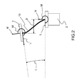
- the tie rod has geometric defects that can be significant, particularly if the number of stacked elements is high. As shown in figure 2 , said geometric defects may be inclination or delocalization defects for example. These geometric defects can cause dynamic defects resulting in radial forces or moments of embedding at the ends of the tie rod.
- the invention proposes a simple and robust solution to solve this double problem. It is essentially based on the use of an active pulling device, controlled via an internal heater said pulling or external.
- the active tie rod consists of several layers of materials alternating layers of materials with a low coefficient of thermal expansion, less than or equal to 1.5 ⁇ 10 -6 , such as invar TM , and layers of materials having a high coefficient of thermal expansion, greater than or equal to about 20 ⁇ 10 -6 , for example aluminum or shape memory alloys.
- the material with low coefficient of thermal expansion may be invar TM .
- the high thermal expansion coefficient material may be aluminum or any shape memory material.
- Spatial appendages are, for example, solar generators or antennas.
- the retractable release mechanism of the active tie rod consists of a set of retractable clamps held in position by means of springs.
- the fixed base may comprise a ball joint in which the active tie is screwed, in order to facilitate the release without shock of said active tie rod.
- the method according to the invention may further comprise a repacking step of said active pulling device.
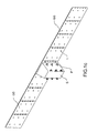
- the figures 1a , 1b , 1 C aim to provide a very simple example of a satellite with deployable space appendages.
- a satellite consisting of a box S with, on either side of said box S, spatial appendages AP, such as solar generators, is shown.
- the AP space appendices are in the stored position.
- the spatial appendages AP here each consist of four panels folded over each other and held in place by a suitable device.
- This adapted device here comprises tripods P on which come to rest the folded AP spatial spacers, each tripod P cooperating with a not shown device consisting for example of a petalable nut associated with a tie rod, each tie passing through each panel at a level of sleeve 1 arranged and integrated in said panel.
- a not shown device consisting for example of a petalable nut associated with a tie rod, each tie passing through each panel at a level of sleeve 1 arranged and integrated in said panel.
- six tripods P associated with six nuts and six tie rods, and six sockets per panel.
- the figure 1b represents the same satellite as on the figure 1a , but whose AP space appendages are being deployed. Indeed, the adapted means for holding in place the AP space appendices allows the release of said AP space appendices at the appropriate time, and the solar panels unfold. The deployment can be controlled by an electric motor not shown.
- the AP space appendages are deployed, allowing the satellite to carry out its mission.
- the figure 2 illustrates the type of geometric defects, already mentioned above, that can present a tie rod in a device for holding in position and releasing spatial appendices of the state of the art.
- problems of inclination I may arise because it is impossible to obtain a perfect parallelism between the sockets 1 of the spatial appendages and the petalable nuts 2.
- a misalignment between a socket 1 and a nut 2 generates a delocalization geometric defect D.
- These problems of inclination I and delocalization D generate dynamic defects, stresses acting on the tie rod 10.
- said tie rod 10 may undergo radial forces L, N, L ', N' exerted at its ends.
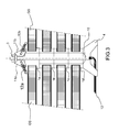
- the figures 3 , 4 , 5 represent the device according to the invention, in an exemplary implementation, during three phases of use.
- the figure 3 represents the device according to the invention in stored position.
- the deployable AP space appendages held in place by the device according to the invention may for example be solar generators. They are in the example of figures 3 , 4 , 5 consisting of four panels folded over each other. It can be any other type of deployable space appendix.
- the spatial appendages AP are not represented in full, the attention being drawn to the device according to the invention.
- This device comprises a fixed base 4, in which is screwed an active tie rod 10 incorporating an internal heater 13; said device also comprises a tensioning nut 3 and a retractable lever release mechanism 11a, 11b, 12a, 12b.
- the device according to the invention may comprise an external heater, not shown.
- each panel at least one opening is provided, within which is integrated a socket 1a, 1b, 1c, 1d.
- These sockets 1 to 1 d allow the passage of the active tie 10.
- each panel of a spatial appendix AP may comprise six sockets.
- the internal heater 13 In the stored position, the internal heater 13 is inactive.
- the panels are stacked on top of one another and are traversed by the active tie rod 10.
- the retractable release mechanism of the tie rod 11a, 11b, 12a, 12b allows the holding in place of stacking panels.
- This retractable release mechanism of the tie rod 11a, 11b, 12a, 12b consists, for example, of a set of retractable clamps 11a and 11b respectively held in positions by springs 12a and 12b.
- An example of a retractable release mechanism of the tie rod adapted to the function of maintenance in place and release necessary for the implementation of the invention is described in particular in the French patent no. 2857936 .
- this retractable lever release mechanism 11a, 11b, 12a, 12b consists on the one hand to cooperate with the active tie rod 10 to maintain the space appendages in the folded position, which will take up the loads due to launch, and on the other hand to fade in the absence of stress, to allow the passage of the active tie rod 10.
- the device comprises a nut 3 for tensioning the assembly. This tensioning allows in particular the passage of launch charges by friction between the various elements.
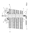
- the scheme of the figure 4 represents the phase of release of the active tie rod 10.
- the internal heater 13 is activated. Said internal heater 13 increases the temperature of the active tie rod 10 which, being made of a suitable material, expands under the effect of heat.
- the constituent material of the active tie rod 10 may be a material with a high coefficient of thermal expansion greater than or equal to 20 ⁇ 10 -6 , such as for example aluminum. It may also be a shape memory alloy.
- the tie rod may also have a more complex structure such as that described in figure 6 .
- the retractable release mechanism of the tie rod 11a, 11b, 12a, 12b folds R on the springs 12a, 12b to yield the passage to the active tie rod 10.
- the deployment of the appendages space can begin.
- the fixed base 4 may comprise a ball joint in which is fixed the active tie rod 10, the presence of this ball can facilitate the release of said active tie rod 10.
- the figure 5 simply represents the beginning of the deployment of the AP space appendices. Due to the extension of the active tie rod 10, said active tie passing through the bushes 1a to 1d of the panels, without contact, the panels can unfold. When the elongation of the active tie rod is sufficient, the internal heater 13 can be deactivated.
- this type of device may, after deployment of the appendages, be reconditioned, since the active tie rod 10 consists of a shape memory alloy. In this case, it is sufficient to fold the panels in the stored position and, after the repackaging of the active tie rod 10, to replace the retractable lever release mechanism 11a, 11b, 12a, 12b and, if necessary, to tighten the nut 3.
- the figure 6 represents an alternative solution to that represented in Figures 3 to 5 Regarding the structure of the active tie 10. Indeed, development constraints may impose an active tie 10 of reduced length.
- a tie rod of the type of figure 6 consisting of several stages alternating layers of material, denoted Al in the figure, with a high coefficient of thermal expansion, greater than or equal to 20 ⁇ 10 -6 , for example aluminum or alloys with shape memory, and layers of material, denoted Inv in the figure, with a very low coefficient of thermal expansion, less than or equal to 1.5 ⁇ 10 -6 , such as invar TM .
- the invention has the advantage of constituting a simple and robust solution to the technical problems listed above, relating to the shock-free release of spatial appendages and the recovery of geometric defects of the tie rods used in the devices for holding and the release of said spatial appendages.
- the solution proposed by the present invention mainly consists in using an active pulling device comprising an internal heater.
- the present invention is used in many cases where the deployment of spatial appendices is necessary, whether solar generators, antennas or even thermal protection panels for example.
Abstract
Description
La présente invention concerne le domaine spatial et, plus précisément, consiste en un système de tirant actif permettant le maintien et la libération sans choc d'appendices spatiaux.The present invention relates to the spatial field and, more specifically, consists of an active pulling system for maintaining and releasing without shock of spatial appendages.
Par appendices spatiaux, on entend des équipements spatiaux destinés à être déployés dans l'espace, tels que des générateurs solaires ou des antennes par exemple. L'invention consiste en une solution simple et robuste permettant la libération sans choc de tels appendices spatiaux.Spatial appendages are spatial devices intended to be deployed in space, such as solar generators or antennas, for example. The invention consists of a simple and robust solution for the release without shock of such spatial appendages.
Ce type de système a pour fonction, dans un premier temps, de maintenir en position stockée un ou des appendices spatiaux, c'est-à-dire, de façon générale, des éléments mobiles déployables de part et d'autre de la caisse du satellite, et, dans un second temps, de libérer sans choc lesdits appendices. L'invention concerne principalement, mais non exclusivement, le cas où les appendices spatiaux sont des générateurs solaires. Le système de maintien en position stockée et de libération des appendices est classiquement constitué principalement d'un écrou pétalable et d'un tirant de mise en tension. Concrètement, dans les systèmes connus, le tirant participe, avec l'écrou, à la mise en tension d'une série d'éléments empilés, tels que des générateurs solaires repliés les uns sur les autres dans le but de minimiser le volume du satellite en vue du lancement, et permettant le passage des charges de lancement par frottement.The purpose of this type of system is, initially, to maintain in the stored position one or more spatial appendages, that is to say, in general, movable elements that can be deployed on either side of the body of the body. satellite, and, in a second time, to release without shock said appendages. The invention relates mainly, but not exclusively, to the case where space appendages are solar generators. The system for maintaining the stored position and releasing the appendages is conventionally constituted mainly of a petal nut and a tensioning tie. Specifically, in known systems, the tie participates, with the nut, in the tensioning of a series of stacked elements, such as solar generators folded over each other in order to minimize the volume of the satellite for launch, and allowing the passage of the launch charges by friction.
Cependant, il est connu que, dans ce type de dispositif, le tirant présente des défauts géométriques qui peuvent être importants, en particulier si le nombre d'éléments empilés est élevé. Comme le montre la
La non prise en compte de ces défauts peut engendrer de graves dysfonctionnements, allant jusqu'au non déploiement des appendices spatiaux, et pouvant donc impliquer une perte de la mission.Failure to take these faults into account can lead to serious malfunctions, up to the non-deployment of spatial appendices, and may therefore imply a loss of the mission.
Un autre problème connu réside dans le choc pouvant se produire lors de la libération du tirant. Le dispositif d'écrou, mentionné précédemment, est chargé de libérer le tirant. Or, ledit tirant se trouve, au moment de sa libération, dans un état contraint et sa brusque libération peut entraîner des chocs pouvant altérer les appendices spatiaux ou le satellite lui-même. Dans le cadre de certains dispositifs actuels, le problème est double. En effet, dans un premier temps, le tirant est libéré par un verrou pyrotechnique dont l'explosion engendre un premier choc. Ensuite, le tirant étant sous tension avant d'être libéré, sa libération brusque, déjà évoquée, peut engendrer des dégradations au niveau des appendices spatiaux ou de la structure porteuse. Dans le but de minimiser ce problème, des écrous dits sans choc, ou « low shock » selon l'expression anglo-saxonne consacrée, ont été mis au point. Ce type d'écrous, complexe, est généralement mono-coup et peut être reconditionné. Cependant, l'aptitude « low shock » de ces écrous n'est applicable qu'au déclenchement de la libération du tirant, et non à la libération des appendices en tant que telle. En effet, les défauts géométriques du tirant ne sont pas réellement compensés et, particulièrement dans le cas où le tirant est de grande dimension, il subsiste une détente brusque du tirant pouvant engendrer un choc parfois important, le tirant venant percuter les appendices spatiaux. Ceci s'explique notamment par le fait que la libération du tirant sous contrainte reste sensible aux déviations angulaires dudit tirant.Another known problem lies in the shock that can occur during the release of the tie rod. The nut device, mentioned above, is responsible for releasing the tie rod. However, said pull rod is, at the time of its release, in a constrained state and its abrupt release can cause shocks that can alter the spatial appendages or the satellite itself. In the context of some current devices, the problem is twofold. Indeed, at first, the tie is released by a pyrotechnic lock whose explosion generates a first shock. Then, the pulling being energized before being released, its abrupt release, already mentioned, can cause degradations at the level of the spatial appendages or the supporting structure. In order to minimize this problem, so-called nuts without shock, or "low shock" according to the English expression devoted, have been developed. This type of nuts, complex, is usually single-shot and can be repackaged. However, the "low shock" ability of these nuts is applicable only to the release of the release of the tie rod, and not to the release of the appendages as such. Indeed, the geometrical defects of the tie rod are not really compensated and, particularly in the case where the tie rod is of large dimension, there remains a sudden relaxation of the pull rod which can generate a shock sometimes important, the pulling from the percussion space appendages. This is explained in particular by the fact that the release of the tie rod under stress remains sensitive to angular deviations of said tie rod.
En résumé, aucune solution satisfaisante n'existe dans l'état de la technique pour à la fois s'affranchir des défauts géométriques du tirant et permettre sa libération sans choc. L'invention propose une solution simple et robuste pour résoudre ce double problème. Elle repose essentiellement sur l'utilisation d'un dispositif de tirant actif, contrôlé par l'intermédiaire d'un réchauffeur interne audit tirant ou externe.In summary, no satisfactory solution exists in the state of the art to both overcome the geometric defects of the tie rod and allow its release without shock. The invention proposes a simple and robust solution to solve this double problem. It is essentially based on the use of an active pulling device, controlled via an internal heater said pulling or external.
A cet effet, l'invention a pour objet un dispositif de tirant actif permettant le maintien et la libération sans choc d'appendices spatiaux, ledit dispositif de tirant actif comprenant :
- une embase fixe,
- un tirant actif vissé dans ladite embase fixe,
- un mécanisme escamotable de libération du tirant actif permettant, en position stockée, le maintien en place dudit tirant actif,
- un écrou de mise sous tension de l'ensemble, caractérisé en ce que ledit tirant actif comporte un réchauffeur interne ou externe, et en ce que ledit tirant actif est constitué au moins partiellement d'un matériau à coefficient de dilatation thermique élevé, supérieur ou égal à environ 20×10-6, par exemple de l'aluminium ou des alliages à mémoire de forme, de sorte que, sous l'action du réchauffeur interne ou externe, le tirant actif peut se dilater, escamotant le mécanisme escamotable de libération du tirant actif, et permettant par conséquent la libération sans choc desdits appendices spatiaux.
- a fixed base,
- an active tie screwed into said fixed base,
- a retractable mechanism for releasing the active tie rod allowing, in the stored position, the holding in place of said active tie rod,
- a nut for energizing the assembly, characterized in that said active tie comprises an internal or external heater, and in that said active tie is at least partially made of a material with a high coefficient of thermal expansion, greater or equal to about 20 × 10 -6 , for example aluminum or shape memory alloys, so that, under the action of the internal or external heater, the active tie can expand, retracting the retractable release mechanism active pulling, and therefore allowing the release without shock of said spatial appendages.
Dans un mode de mise en oeuvre de l'invention, le tirant actif est constitué de plusieurs couches de matériaux alternant des couches de matériaux à coefficient de dilatation thermique faible, inférieur ou égal à 1,5×10⁻⁶, tel que de l'invar™, et des couches de matériaux à coefficient de dilatation thermique élevé, supérieur ou égal à environ 20×10-6, par exemple de l'aluminium ou des alliages à mémoire de forme.In one embodiment of the invention, the active tie rod consists of several layers of materials alternating layers of materials with a low coefficient of thermal expansion, less than or equal to 1.5 × 10 -6 , such as invar ™ , and layers of materials having a high coefficient of thermal expansion, greater than or equal to about 20 × 10 -6 , for example aluminum or shape memory alloys.
Le matériau à coefficient de dilatation thermique faible peut être de l'invar™.The material with low coefficient of thermal expansion may be invar ™ .
Le matériau à coefficient de dilatation thermique élevé peut être de l'aluminium ou un quelconque matériau à mémoire de forme.The high thermal expansion coefficient material may be aluminum or any shape memory material.
Les appendices spatiaux sont, par exemple, des générateurs solaires ou des antennes.Spatial appendages are, for example, solar generators or antennas.
Avantageusement, le mécanisme escamotable de libération du tirant actif est constitué d'un ensemble de pinces escamotables maintenues en position par l'intermédiaire de ressorts.Advantageously, the retractable release mechanism of the active tie rod consists of a set of retractable clamps held in position by means of springs.
Avantageusement, l'embase fixe peut comprendre une rotule dans laquelle le tirant actif est vissé, en vue de faciliter la libération sans choc dudit tirant actif.Advantageously, the fixed base may comprise a ball joint in which the active tie is screwed, in order to facilitate the release without shock of said active tie rod.
L'invention consiste en outre en un procédé de libération sans choc d'appendices spatiaux, caractérisé en ce qu'il comprend l'utilisation d'un dispositif de tirant actif tel que précédemment décrit, et mettant en oeuvre les étapes suivantes :
- une étape de libération au cours de laquelle le réchauffeur interne ou externe du tirant actif est activé et provoque l'allongement dudit tirant actif, et, sous l'effet notamment de l'allongement du tirant actif, le mécanisme escamotable de libération du tirant actif se rétracte et laisse le passage libre au tirant actif,
- une étape de déploiement au cours de laquelle l'ouverture complète des appendices spatiaux est effectuée.
- a release step during which the internal or external heater of the active tie rod is activated and causes the elongation of said active tie rod, and, particularly as a result of the extension of the active tie rod, the retractable mechanism for releasing the active tie rod retracts and leaves the free passage to active pulling,
- a deployment step during which the complete opening of the spatial appendages is performed.
Avantageusement, le procédé selon l'invention peut comprendre en outre une étape de reconditionnement dudit dispositif de tirant actif.Advantageously, the method according to the invention may further comprise a repacking step of said active pulling device.
Avantageusement, le tirant actif étant constitué d'un matériau à mémoire de forme, l'étape de reconditionnement se traduit par :
- le chauffage du tirant par l'action du réchauffeur interne ou externe,
- la mise en compression du tirant au moyen d'une presse,
- le refroidissement du tirant actif qui reprend sa forme initiale,
- le repositionnement des appendices spatiaux et la remise en place du mécanisme escamotable de libération du tirant actif.
- heating the tie rod by the action of the internal or external heater,
- compressing the tie rod by means of a press,
- the cooling of the active tie which resumes its initial shape,
- the repositioning of the spatial appendages and the repositioning of the retractable mechanism of release of the active tie rod.
D'autres caractéristiques et avantages de l'invention apparaîtront à l'aide de la description qui suit faite en regard des dessins annexés qui représentent :
- la
figure 1 a : la vue schématique d'un satellite comprenant des appendices spatiaux en position stockée ; - la
figure 1b : la vue schématique d'un satellite comprenant des appendices spatiaux en cours de déploiement ; - la
figure 1c : la vue schématique d'un satellite comprenant des appendices spatiaux en position déployée ; - la
figure 2 : la représentation sous forme simplifiée du type de défauts géométriques et dynamiques que peut présenter un tirant ; - la
figure 3 : le schéma d'un exemple de système de tirant actif selon l'invention, en position stockée ; - la
figure 4 : le schéma d'un exemple de système de tirant actif selon l'invention, au déclenchement de la libération du tirant ; - la
figure 5 : le schéma d'un exemple de système de tirant actif selon l'invention, en début de phase de déploiement des appendices spatiaux ; - la
figure 6 : un exemple de tirant multicouche, selon un mode de mise en oeuvre de l'invention.
- the
figure 1 a: the schematic view of a satellite including spatial appendages in stored position; - the
figure 1b : the schematic view of a satellite with spatial appendages being deployed; - the
figure 1c : the schematic view of a satellite comprising space appendages in the deployed position; - the
figure 2 : the representation in simplified form of the type of geometric and dynamic defects that can present a tie rod; - the
figure 3 : the diagram of an example of active pulling system according to the invention, in the stored position; - the
figure 4 : the diagram of an example of active pulling system according to the invention, at the triggering of the release of the tie rod; - the
figure 5 : the diagram of an example of active pulling system according to the invention, early deployment phase of the spatial appendages; - the
figure 6 an example of multilayer pulling, according to an embodiment of the invention.
Les
Evidemment, c'est dans cette position stockée que le satellite doit être intégré à la coiffe du lanceur spatial chargé de son expédition.Obviously, it is in this stored position that the satellite must be integrated into the cap of the space launcher responsible for its expedition.
La
Sur la
La
Les
La
Il faut noter qu'en lieu et place ou en complément du réchauffeur interne 13, le dispositif selon l'invention peut comprendre un réchauffeur externe, non représenté.It should be noted that instead of or in addition to the
Au sein de chaque panneau, au moins une ouverture est ménagée, au sein de laquelle est intégrée une douille 1 a, 1 b, 1 c, 1 d. Ces douilles 1 a à 1 d permettent le passage du tirant actif 10. En fonction de la taille des appendices spatiaux, il peut y avoir plusieurs ouvertures et autant de douilles par élément. Par exemple, comme cela est représenté sur les
En position stockée, le réchauffeur interne 13 est inactif. Les panneaux sont empilés les uns sur les autres et sont traversés par le tirant actif 10. A l'extrémité opposée à l'embase fixe 4, le mécanisme escamotable de libération du tirant 11 a, 11 b, 12a, 12b permet le maintien en place de l'empilement des panneaux. Ce mécanisme escamotable de libération du tirant 11 a, 11 b, 12a, 12b est constitué, par exemple, d'un ensemble de pinces escamotables 11 a et 11 b, respectivement maintenues en positions par des ressorts 12a et 12b. Un exemple de mécanisme escamotable de libération du tirant adapté à la fonction de maintien en place et de libération nécessaire à la mise en oeuvre de l'invention est notamment décrit dans le brevet français n°
Enfin, le dispositif comprend un écrou 3 de mise en tension l'ensemble. Cette mise en tension permet notamment le passage des charges de lancement par frottement entre les différents éléments.Finally, the device comprises a
Le schéma de la
La
On notera que durant une phase d'essais au sol, ce type de dispositif peut, après déploiement des appendices, être reconditionné, dès lors que le tirant actif 10 est constitué d'un alliage à mémoire de forme. Dans ce cas, il suffit de replier les panneaux en position stockée et, après le reconditionnement du tirant actif 10, de remettre en place le mécanisme escamotable de libération du tirant 11a, 11b, 12a, 12b et, si besoin, de resserrer l'écrou 3.Note that during a ground test phase, this type of device may, after deployment of the appendages, be reconditioned, since the
La
En résumé, l'invention présente l'avantage de constituer une solution simple et robuste aux problèmes techniques énumérés précédemment, relatifs à la libération sans choc d'appendices spatiaux et à la reprise des défauts géométriques des tirants utilisés dans les dispositifs permettant le maintien et la libération desdits appendices spatiaux. La solution proposée par la présente invention consiste principalement à utiliser un dispositif de tirant actif comportant un réchauffeur interne.In summary, the invention has the advantage of constituting a simple and robust solution to the technical problems listed above, relating to the shock-free release of spatial appendages and the recovery of geometric defects of the tie rods used in the devices for holding and the release of said spatial appendages. The The solution proposed by the present invention mainly consists in using an active pulling device comprising an internal heater.
Il est à noter que la présente invention est utilisable dans de nombreux cas où le déploiement d'appendices spatiaux est nécessaire, qu'il s'agisse de générateurs solaires, d'antennes, ou encore de panneaux de protection thermique par exemple.It should be noted that the present invention is used in many cases where the deployment of spatial appendices is necessary, whether solar generators, antennas or even thermal protection panels for example.
Claims (10)
Applications Claiming Priority (1)
| Application Number | Priority Date | Filing Date | Title |
|---|---|---|---|
| FR0905401A FR2952353B1 (en) | 2009-11-10 | 2009-11-10 | ACTIVE TENDER SYSTEM FOR THE MAINTENANCE AND RELEASE WITHOUT SHOCK OF SPACE APPENDICES |
Publications (2)
| Publication Number | Publication Date |
|---|---|
| EP2319764A1 true EP2319764A1 (en) | 2011-05-11 |
| EP2319764B1 EP2319764B1 (en) | 2013-07-03 |
Family
ID=42224350
Family Applications (1)
| Application Number | Title | Priority Date | Filing Date |
|---|---|---|---|
| EP10185980.9A Active EP2319764B1 (en) | 2009-11-10 | 2010-10-01 | System of tie rods enabling shock-free holding and release of space appendages |
Country Status (6)
| Country | Link |
|---|---|
| US (1) | US8757553B2 (en) |
| EP (1) | EP2319764B1 (en) |
| JP (1) | JP5816968B2 (en) |
| CN (1) | CN102050229B (en) |
| ES (1) | ES2426605T3 (en) |
| FR (1) | FR2952353B1 (en) |
Cited By (2)
| Publication number | Priority date | Publication date | Assignee | Title |
|---|---|---|---|---|
| EP3181461A1 (en) * | 2015-12-18 | 2017-06-21 | Thales | Device for holding and releasing appendages |
| US20190085564A1 (en) * | 2017-09-21 | 2019-03-21 | Newtonoid Technologies, L.L.C. | Shingle clip system and method |
Families Citing this family (13)
| Publication number | Priority date | Publication date | Assignee | Title |
|---|---|---|---|---|
| US8683755B1 (en) * | 2010-01-21 | 2014-04-01 | Deployable Space Systems, Inc. | Directionally controlled elastically deployable roll-out solar array |
| CN103662099B (en) * | 2012-09-20 | 2015-12-09 | 中国科学院沈阳自动化研究所 | A kind of deployable space structures |
| CN103700920B (en) * | 2012-09-27 | 2016-07-06 | 上海宇航系统工程研究所 | The spliced expanding unit of aerospace craft flat plane antenna |
| CN102923319B (en) * | 2012-11-16 | 2015-11-18 | 上海宇航系统工程研究所 | A kind of aerospacecraft roof type unfolding and locking device |
| US9612039B2 (en) * | 2013-05-14 | 2017-04-04 | Mobile Grid, Llc | Mobile solar power rack |
| US9446864B2 (en) * | 2014-10-17 | 2016-09-20 | The Boeing Company | NANOSAT electrothermal deployment system |
| US9004410B1 (en) | 2014-10-24 | 2015-04-14 | Alliance Spacesystems, Llc | Deployable boom for collecting electromagnetic energy |
| US10059471B2 (en) | 2014-10-24 | 2018-08-28 | Solaero Technologies Corp. | Method for releasing a deployable boom |
| CN105416612B (en) * | 2015-11-06 | 2017-06-13 | 北京空间飞行器总体设计部 | One kind is mechanically decoupled nut and its long-distance controlling apparatus |
| CN109279051A (en) * | 2017-07-23 | 2019-01-29 | 北京遥感设备研究所 | A kind of adaptive strain swept area thermal controls apparatus |
| CN109305391B (en) * | 2018-08-08 | 2021-12-21 | 上海宇航系统工程研究所 | Compression release mechanism and method thereof |
| CN109760855B (en) * | 2019-03-01 | 2020-10-20 | 哈尔滨工业大学 | Flexible space solar sailboard |
| CN114171882B (en) * | 2021-10-11 | 2023-05-05 | 北京理工大学 | One-arrow multi-star SAR satellite flattened antenna lamination device |
Citations (3)
| Publication number | Priority date | Publication date | Assignee | Title |
|---|---|---|---|---|
| EP0402263A1 (en) * | 1989-06-09 | 1990-12-12 | AEROSPATIALE Société Nationale Industrielle | Device for a temporary connection, especially for the appendix of an artificial satellite and process of opening this connection |
| JPH10310100A (en) * | 1997-05-09 | 1998-11-24 | Nec Corp | Space structure separation mechanism, and separation method thereof |
| FR2857936A1 (en) * | 2003-07-22 | 2005-01-28 | Cit Alcatel | GERMATING TICKER RELEASING DEVICE FOR DEPLOYABLE STRUCTURE |
Family Cites Families (10)
| Publication number | Priority date | Publication date | Assignee | Title |
|---|---|---|---|---|
| NL8400362A (en) * | 1984-02-06 | 1985-09-02 | Fokker Bv | DEVICE FOR HOLDING OR RELEASING SOLAR PANELS OF A SPACE VESSEL. |
| FR2735187B1 (en) * | 1995-06-06 | 1997-08-29 | Aerospatiale | SINGLE ACTUATOR PUSH-BUTTON MOVED BY MEMORY MATERIAL. |
| US6175989B1 (en) * | 1998-05-26 | 2001-01-23 | Lockheed Corp | Shape memory alloy controllable hinge apparatus |
| DE19843965C2 (en) * | 1998-09-24 | 2000-07-13 | Daimler Chrysler Ag | Hold and release mechanism with a shape memory actuator |
| US6299105B1 (en) * | 1999-02-18 | 2001-10-09 | Trw Inc. | Spacecraft with an environmentally released deployable structure |
| DE10043631C2 (en) * | 2000-06-29 | 2003-04-10 | Astrium Gmbh | Linear actuation device, in particular for space vehicles and solar generator deployment system |
| FR2825766B1 (en) * | 2001-06-08 | 2003-10-10 | Lacroix Soc E | THERMAL EFFECT CONTROLLED RELEASE MECHANISM |
| US7422403B1 (en) * | 2003-10-23 | 2008-09-09 | Tini Alloy Company | Non-explosive releasable coupling device |
| CN201128483Y (en) * | 2007-11-06 | 2008-10-08 | 北京空间飞行器总体设计部 | Folding type rigid and semi-rigid solar array secondary pressing and releasing mechanism |
| JP2009166678A (en) * | 2008-01-16 | 2009-07-30 | Mitsubishi Electric Corp | Securement releasing device |
-
2009
- 2009-11-10 FR FR0905401A patent/FR2952353B1/en not_active Expired - Fee Related
-
2010
- 2010-10-01 ES ES10185980T patent/ES2426605T3/en active Active
- 2010-10-01 EP EP10185980.9A patent/EP2319764B1/en active Active
- 2010-10-26 US US12/912,515 patent/US8757553B2/en active Active
- 2010-11-05 CN CN201010548999.5A patent/CN102050229B/en not_active Expired - Fee Related
- 2010-11-09 JP JP2010251012A patent/JP5816968B2/en not_active Expired - Fee Related
Patent Citations (3)
| Publication number | Priority date | Publication date | Assignee | Title |
|---|---|---|---|---|
| EP0402263A1 (en) * | 1989-06-09 | 1990-12-12 | AEROSPATIALE Société Nationale Industrielle | Device for a temporary connection, especially for the appendix of an artificial satellite and process of opening this connection |
| JPH10310100A (en) * | 1997-05-09 | 1998-11-24 | Nec Corp | Space structure separation mechanism, and separation method thereof |
| FR2857936A1 (en) * | 2003-07-22 | 2005-01-28 | Cit Alcatel | GERMATING TICKER RELEASING DEVICE FOR DEPLOYABLE STRUCTURE |
Cited By (4)
| Publication number | Priority date | Publication date | Assignee | Title |
|---|---|---|---|---|
| EP3181461A1 (en) * | 2015-12-18 | 2017-06-21 | Thales | Device for holding and releasing appendages |
| FR3045851A1 (en) * | 2015-12-18 | 2017-06-23 | Thales Sa | DEVICE FOR HOLDING AND RELEASING APPENDICES |
| US10723488B2 (en) | 2015-12-18 | 2020-07-28 | Thales | Device for retaining and releasing appendages |
| US20190085564A1 (en) * | 2017-09-21 | 2019-03-21 | Newtonoid Technologies, L.L.C. | Shingle clip system and method |
Also Published As
| Publication number | Publication date |
|---|---|
| US20110108670A1 (en) | 2011-05-12 |
| US8757553B2 (en) | 2014-06-24 |
| EP2319764B1 (en) | 2013-07-03 |
| JP5816968B2 (en) | 2015-11-18 |
| FR2952353A1 (en) | 2011-05-13 |
| FR2952353B1 (en) | 2011-12-09 |
| CN102050229B (en) | 2015-05-27 |
| ES2426605T3 (en) | 2013-10-24 |
| JP2011102118A (en) | 2011-05-26 |
| CN102050229A (en) | 2011-05-11 |
Similar Documents
| Publication | Publication Date | Title |
|---|---|---|
| EP2319764B1 (en) | System of tie rods enabling shock-free holding and release of space appendages | |
| EP1887139B1 (en) | Method of removing a tight cable, associated system and device | |
| EP2143641B1 (en) | Tape measure with thermal unrolling and unrolling structure comprising such a tape measure | |
| EP3181461B1 (en) | Device for holding and releasing appendages | |
| EP2471713B1 (en) | Unreelable square framed solar generator | |
| FR3017669A1 (en) | ||
| CA2863562A1 (en) | Receiving assembly for receiving a seagoing vessel and system for recovering and deploying such a vessel in the sea | |
| FR2977457A1 (en) | Parasol for protecting user from sunlight, has structure moving blades from folded position to unfolded position for forming surface to create shade, where blades are connected to frame to move in parallel with each other between positions | |
| EP1873061B1 (en) | Retractable structure comprising rigid elements on board a spacecraft | |
| EP1422763A1 (en) | Solar cell for solar generator panel, solar generator panel and spacecraft | |
| FR2949821A1 (en) | ENGINE FUSEE DIVERGENT DEPLOYABLE | |
| FR3028842A1 (en) | RETRACTABLE DEPLOYABLE STRUCTURE WITH METER-RIBBON | |
| FR2968234A1 (en) | ADJUSTABLE TORQUE MOTORIZATION SYSTEM FOR DEPLOYABLE SPATIAL STRUCTURES | |
| EP3396300B1 (en) | Actuating device for ejecting at least one removable part of a missile, in particular a fairing | |
| FR3027065A1 (en) | DEPLOYABLE GRID WITH FINS FOR AN AIRCRAFT TURBOMACHINE PUSH INVERSION SYSTEM | |
| FR3016674A1 (en) | PULSE PUSHING DEVICE | |
| EP2138698B1 (en) | Device for absorbing the lateral forces of the jet flow separation acting on the nozzle of a rocket engine | |
| WO2015014941A1 (en) | Method and device for connecting and separating two elements with combined connecting and separating means | |
| EP2520494B1 (en) | Device for protecting a multiple mirror optical instrument | |
| EP2461065B1 (en) | Hinge device with a strand bundle in a shape memory material | |
| FR3054576B1 (en) | DEVICE FOR PROTECTION AGAINST A PROJECTED OBJECT | |
| EP1500590B1 (en) | Restrainer rod release device for a deployable structure | |
| WO2019110889A1 (en) | Improved device for clamping heat shields for rocket engine diverging nozzle section | |
| FR2944542A1 (en) | Support stud for e.g. boat cradle, to support wall in construction industry, has blocking units blocking rotation of cam in raised position, and external tube including bearing surface on which active surface is supported | |
| FR3065203B1 (en) | LIGHT TUBULAR STRUCTURE |
Legal Events
| Date | Code | Title | Description |
|---|---|---|---|
| PUAI | Public reference made under article 153(3) epc to a published international application that has entered the european phase |
Free format text: ORIGINAL CODE: 0009012 |
|
| AK | Designated contracting states |
Kind code of ref document: A1 Designated state(s): AL AT BE BG CH CY CZ DE DK EE ES FI FR GB GR HR HU IE IS IT LI LT LU LV MC MK MT NL NO PL PT RO RS SE SI SK SM TR |
|
| AX | Request for extension of the european patent |
Extension state: BA ME |
|
| 17P | Request for examination filed |
Effective date: 20110728 |
|
| RIC1 | Information provided on ipc code assigned before grant |
Ipc: B64G 1/22 20060101AFI20121220BHEP Ipc: B64G 1/64 20060101ALI20121220BHEP |
|
| GRAP | Despatch of communication of intention to grant a patent |
Free format text: ORIGINAL CODE: EPIDOSNIGR1 |
|
| RIN1 | Information on inventor provided before grant (corrected) |
Inventor name: BAUDASSE, YANNICK Inventor name: LEGRAND, SILVAIN |
|
| GRAS | Grant fee paid |
Free format text: ORIGINAL CODE: EPIDOSNIGR3 |
|
| GRAA | (expected) grant |
Free format text: ORIGINAL CODE: 0009210 |
|
| AK | Designated contracting states |
Kind code of ref document: B1 Designated state(s): AL AT BE BG CH CY CZ DE DK EE ES FI FR GB GR HR HU IE IS IT LI LT LU LV MC MK MT NL NO PL PT RO RS SE SI SK SM TR |
|
| REG | Reference to a national code |
Ref country code: GB Ref legal event code: FG4D Free format text: NOT ENGLISH |
|
| REG | Reference to a national code |
Ref country code: CH Ref legal event code: EP Ref country code: AT Ref legal event code: REF Ref document number: 619575 Country of ref document: AT Kind code of ref document: T Effective date: 20130715 |
|
| REG | Reference to a national code |
Ref country code: IE Ref legal event code: FG4D Free format text: LANGUAGE OF EP DOCUMENT: FRENCH |
|
| REG | Reference to a national code |
Ref country code: DE Ref legal event code: R096 Ref document number: 602010008171 Country of ref document: DE Effective date: 20130829 |
|
| REG | Reference to a national code |
Ref country code: ES Ref legal event code: FG2A Ref document number: 2426605 Country of ref document: ES Kind code of ref document: T3 Effective date: 20131024 |
|
| PG25 | Lapsed in a contracting state [announced via postgrant information from national office to epo] |
Ref country code: SI Free format text: LAPSE BECAUSE OF FAILURE TO SUBMIT A TRANSLATION OF THE DESCRIPTION OR TO PAY THE FEE WITHIN THE PRESCRIBED TIME-LIMIT Effective date: 20130703 |
|
| REG | Reference to a national code |
Ref country code: NL Ref legal event code: T3 |
|
| REG | Reference to a national code |
Ref country code: AT Ref legal event code: MK05 Ref document number: 619575 Country of ref document: AT Kind code of ref document: T Effective date: 20130703 |
|
| REG | Reference to a national code |
Ref country code: LT Ref legal event code: MG4D |
|
| PG25 | Lapsed in a contracting state [announced via postgrant information from national office to epo] |
Ref country code: SE Free format text: LAPSE BECAUSE OF FAILURE TO SUBMIT A TRANSLATION OF THE DESCRIPTION OR TO PAY THE FEE WITHIN THE PRESCRIBED TIME-LIMIT Effective date: 20130703 Ref country code: AT Free format text: LAPSE BECAUSE OF FAILURE TO SUBMIT A TRANSLATION OF THE DESCRIPTION OR TO PAY THE FEE WITHIN THE PRESCRIBED TIME-LIMIT Effective date: 20130703 Ref country code: CY Free format text: LAPSE BECAUSE OF FAILURE TO SUBMIT A TRANSLATION OF THE DESCRIPTION OR TO PAY THE FEE WITHIN THE PRESCRIBED TIME-LIMIT Effective date: 20130717 Ref country code: HR Free format text: LAPSE BECAUSE OF FAILURE TO SUBMIT A TRANSLATION OF THE DESCRIPTION OR TO PAY THE FEE WITHIN THE PRESCRIBED TIME-LIMIT Effective date: 20130703 Ref country code: PT Free format text: LAPSE BECAUSE OF FAILURE TO SUBMIT A TRANSLATION OF THE DESCRIPTION OR TO PAY THE FEE WITHIN THE PRESCRIBED TIME-LIMIT Effective date: 20131104 Ref country code: NO Free format text: LAPSE BECAUSE OF FAILURE TO SUBMIT A TRANSLATION OF THE DESCRIPTION OR TO PAY THE FEE WITHIN THE PRESCRIBED TIME-LIMIT Effective date: 20131003 Ref country code: IS Free format text: LAPSE BECAUSE OF FAILURE TO SUBMIT A TRANSLATION OF THE DESCRIPTION OR TO PAY THE FEE WITHIN THE PRESCRIBED TIME-LIMIT Effective date: 20131103 Ref country code: LT Free format text: LAPSE BECAUSE OF FAILURE TO SUBMIT A TRANSLATION OF THE DESCRIPTION OR TO PAY THE FEE WITHIN THE PRESCRIBED TIME-LIMIT Effective date: 20130703 |
|
| PG25 | Lapsed in a contracting state [announced via postgrant information from national office to epo] |
Ref country code: FI Free format text: LAPSE BECAUSE OF FAILURE TO SUBMIT A TRANSLATION OF THE DESCRIPTION OR TO PAY THE FEE WITHIN THE PRESCRIBED TIME-LIMIT Effective date: 20130703 Ref country code: PL Free format text: LAPSE BECAUSE OF FAILURE TO SUBMIT A TRANSLATION OF THE DESCRIPTION OR TO PAY THE FEE WITHIN THE PRESCRIBED TIME-LIMIT Effective date: 20130703 Ref country code: GR Free format text: LAPSE BECAUSE OF FAILURE TO SUBMIT A TRANSLATION OF THE DESCRIPTION OR TO PAY THE FEE WITHIN THE PRESCRIBED TIME-LIMIT Effective date: 20131004 Ref country code: LV Free format text: LAPSE BECAUSE OF FAILURE TO SUBMIT A TRANSLATION OF THE DESCRIPTION OR TO PAY THE FEE WITHIN THE PRESCRIBED TIME-LIMIT Effective date: 20130703 |
|
| PG25 | Lapsed in a contracting state [announced via postgrant information from national office to epo] |
Ref country code: CY Free format text: LAPSE BECAUSE OF FAILURE TO SUBMIT A TRANSLATION OF THE DESCRIPTION OR TO PAY THE FEE WITHIN THE PRESCRIBED TIME-LIMIT Effective date: 20130703 |
|
| BERE | Be: lapsed |
Owner name: THALES Effective date: 20131031 |
|
| PG25 | Lapsed in a contracting state [announced via postgrant information from national office to epo] |
Ref country code: EE Free format text: LAPSE BECAUSE OF FAILURE TO SUBMIT A TRANSLATION OF THE DESCRIPTION OR TO PAY THE FEE WITHIN THE PRESCRIBED TIME-LIMIT Effective date: 20130703 Ref country code: DK Free format text: LAPSE BECAUSE OF FAILURE TO SUBMIT A TRANSLATION OF THE DESCRIPTION OR TO PAY THE FEE WITHIN THE PRESCRIBED TIME-LIMIT Effective date: 20130703 Ref country code: SK Free format text: LAPSE BECAUSE OF FAILURE TO SUBMIT A TRANSLATION OF THE DESCRIPTION OR TO PAY THE FEE WITHIN THE PRESCRIBED TIME-LIMIT Effective date: 20130703 Ref country code: CZ Free format text: LAPSE BECAUSE OF FAILURE TO SUBMIT A TRANSLATION OF THE DESCRIPTION OR TO PAY THE FEE WITHIN THE PRESCRIBED TIME-LIMIT Effective date: 20130703 Ref country code: RO Free format text: LAPSE BECAUSE OF FAILURE TO SUBMIT A TRANSLATION OF THE DESCRIPTION OR TO PAY THE FEE WITHIN THE PRESCRIBED TIME-LIMIT Effective date: 20130703 |
|
| PLBE | No opposition filed within time limit |
Free format text: ORIGINAL CODE: 0009261 |
|
| STAA | Information on the status of an ep patent application or granted ep patent |
Free format text: STATUS: NO OPPOSITION FILED WITHIN TIME LIMIT |
|
| PG25 | Lapsed in a contracting state [announced via postgrant information from national office to epo] |
Ref country code: MC Free format text: LAPSE BECAUSE OF FAILURE TO SUBMIT A TRANSLATION OF THE DESCRIPTION OR TO PAY THE FEE WITHIN THE PRESCRIBED TIME-LIMIT Effective date: 20130703 |
|
| 26N | No opposition filed |
Effective date: 20140404 |
|
| REG | Reference to a national code |
Ref country code: DE Ref legal event code: R097 Ref document number: 602010008171 Country of ref document: DE Effective date: 20140404 |
|
| REG | Reference to a national code |
Ref country code: IE Ref legal event code: MM4A |
|
| PG25 | Lapsed in a contracting state [announced via postgrant information from national office to epo] |
Ref country code: BE Free format text: LAPSE BECAUSE OF NON-PAYMENT OF DUE FEES Effective date: 20131031 |
|
| PG25 | Lapsed in a contracting state [announced via postgrant information from national office to epo] |
Ref country code: IE Free format text: LAPSE BECAUSE OF NON-PAYMENT OF DUE FEES Effective date: 20131001 |
|
| PG25 | Lapsed in a contracting state [announced via postgrant information from national office to epo] |
Ref country code: SM Free format text: LAPSE BECAUSE OF FAILURE TO SUBMIT A TRANSLATION OF THE DESCRIPTION OR TO PAY THE FEE WITHIN THE PRESCRIBED TIME-LIMIT Effective date: 20130703 |
|
| REG | Reference to a national code |
Ref country code: CH Ref legal event code: PL |
|
| PG25 | Lapsed in a contracting state [announced via postgrant information from national office to epo] |
Ref country code: TR Free format text: LAPSE BECAUSE OF FAILURE TO SUBMIT A TRANSLATION OF THE DESCRIPTION OR TO PAY THE FEE WITHIN THE PRESCRIBED TIME-LIMIT Effective date: 20130703 |
|
| PG25 | Lapsed in a contracting state [announced via postgrant information from national office to epo] |
Ref country code: LI Free format text: LAPSE BECAUSE OF NON-PAYMENT OF DUE FEES Effective date: 20141031 Ref country code: LU Free format text: LAPSE BECAUSE OF NON-PAYMENT OF DUE FEES Effective date: 20131001 Ref country code: BG Free format text: LAPSE BECAUSE OF FAILURE TO SUBMIT A TRANSLATION OF THE DESCRIPTION OR TO PAY THE FEE WITHIN THE PRESCRIBED TIME-LIMIT Effective date: 20130703 Ref country code: MK Free format text: LAPSE BECAUSE OF FAILURE TO SUBMIT A TRANSLATION OF THE DESCRIPTION OR TO PAY THE FEE WITHIN THE PRESCRIBED TIME-LIMIT Effective date: 20130703 Ref country code: CH Free format text: LAPSE BECAUSE OF NON-PAYMENT OF DUE FEES Effective date: 20141031 Ref country code: RS Free format text: LAPSE BECAUSE OF FAILURE TO SUBMIT A TRANSLATION OF THE DESCRIPTION OR TO PAY THE FEE WITHIN THE PRESCRIBED TIME-LIMIT Effective date: 20131003 Ref country code: HU Free format text: LAPSE BECAUSE OF FAILURE TO SUBMIT A TRANSLATION OF THE DESCRIPTION OR TO PAY THE FEE WITHIN THE PRESCRIBED TIME-LIMIT; INVALID AB INITIO Effective date: 20101001 |
|
| PG25 | Lapsed in a contracting state [announced via postgrant information from national office to epo] |
Ref country code: MT Free format text: LAPSE BECAUSE OF FAILURE TO SUBMIT A TRANSLATION OF THE DESCRIPTION OR TO PAY THE FEE WITHIN THE PRESCRIBED TIME-LIMIT Effective date: 20130703 |
|
| REG | Reference to a national code |
Ref country code: FR Ref legal event code: PLFP Year of fee payment: 7 |
|
| REG | Reference to a national code |
Ref country code: FR Ref legal event code: PLFP Year of fee payment: 8 |
|
| REG | Reference to a national code |
Ref country code: FR Ref legal event code: PLFP Year of fee payment: 9 |
|
| PG25 | Lapsed in a contracting state [announced via postgrant information from national office to epo] |
Ref country code: AL Free format text: LAPSE BECAUSE OF FAILURE TO SUBMIT A TRANSLATION OF THE DESCRIPTION OR TO PAY THE FEE WITHIN THE PRESCRIBED TIME-LIMIT Effective date: 20130703 |
|
| PGFP | Annual fee paid to national office [announced via postgrant information from national office to epo] |
Ref country code: IT Payment date: 20180713 Year of fee payment: 10 |
|
| REG | Reference to a national code |
Ref country code: NL Ref legal event code: MM Effective date: 20191101 |
|
| PG25 | Lapsed in a contracting state [announced via postgrant information from national office to epo] |
Ref country code: NL Free format text: LAPSE BECAUSE OF NON-PAYMENT OF DUE FEES Effective date: 20191101 |
|
| PG25 | Lapsed in a contracting state [announced via postgrant information from national office to epo] |
Ref country code: IT Free format text: LAPSE BECAUSE OF NON-PAYMENT OF DUE FEES Effective date: 20191001 |
|
| PGFP | Annual fee paid to national office [announced via postgrant information from national office to epo] |
Ref country code: GB Payment date: 20230914 Year of fee payment: 14 |
|
| PGFP | Annual fee paid to national office [announced via postgrant information from national office to epo] |
Ref country code: FR Payment date: 20230921 Year of fee payment: 14 |
|
| PGFP | Annual fee paid to national office [announced via postgrant information from national office to epo] |
Ref country code: ES Payment date: 20231109 Year of fee payment: 14 |
|
| PGFP | Annual fee paid to national office [announced via postgrant information from national office to epo] |
Ref country code: DE Payment date: 20230919 Year of fee payment: 14 |